Chapitre Le boîtier de commande
Chapitre Le boîtier de commande
Chapitre Le boîtier de commande
- No tags were found...

Create successful ePaper yourself
Turn your PDF publications into a flip-book with our unique Google optimized e-Paper software.
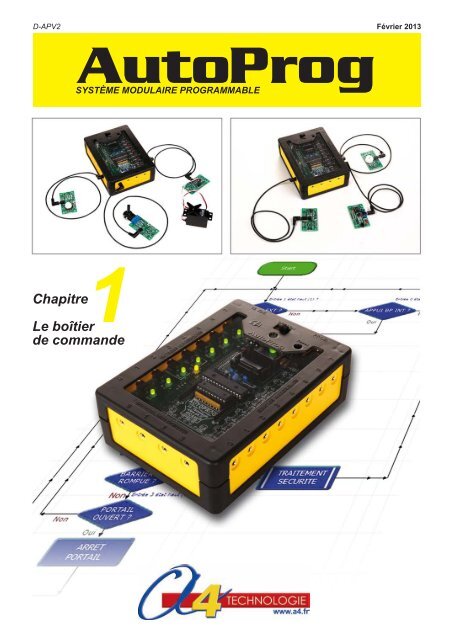
D-APV2Février 2013SYSTÈME MODULAIRE PROGRAMMABLE1<strong>Chapitre</strong><strong>Le</strong> boîtier<strong>de</strong> comman<strong>de</strong>
Février 2013Etienne Bernot - André BernotPascal Collette - Denis Hoffschir1Boîtier <strong>de</strong> comman<strong>de</strong> AutProg V2Edité par la société A4 Technologie5 avenue <strong>de</strong> l’Atlantique - 91940 <strong>Le</strong>s UlisTél. : 01 64 86 41 00 - Fax : 01 64 46 31 19www.a4.frSOMMAIRESchéma électronique 1.1.2Eclaté du boîtier 1.1.4Conseils généraux pour l’implantation <strong>de</strong>s composants 1.1.5Version <strong>de</strong> basePerspective et nomenclature face A 1.1.8Implantation <strong>de</strong>s composants face A 1.1.8Perspective et nomenclature face B 1.1.10Implantation <strong>de</strong>s composants face B 1.1.10Conseils pour l’implantation <strong>de</strong>s composants 1.1.12Montage du boîtier 1.1.13Mise en service du boîtier 1.1.14Description du kit 1.1.15OptionsTransmission sans filPerspectives et nomenclature 1.1.20Implantation <strong>de</strong>s composants 1.1.21Mise en service du boîtier 1.1.22Description du kit 1.1.23Horloge temps réel I2CPerspectives et nomenclature 1.1.26Implantation <strong>de</strong>s composants 1.1.27Description du kit 1.1.28Mémoire I2CPerspectives et nomenclature 1.1.30Implantation <strong>de</strong>s composants 1.1.31Description du kit 1.1.32ConnectiqueConnection entrées/sorties : perspectives, nomenclature, implantation et mise en service 1.1.34Connection par borniers à vis : perspective, implantation et mise en service 1.1.36Ce dossier et toutes les ressources numériques sont duplicables pour les élèves, en usage interne à l’établissement scolaire*.* La duplication est autorisée sans limite <strong>de</strong> quantité au sein <strong>de</strong>s établissements scolaires, à seules fins pédagogiques, à la condition que soit cité le nom <strong>de</strong> l’éditeur : Sté A4. La copie ou la diffusionpar quelque moyen que ce soit à <strong>de</strong>s fins commerciales n’est pas autorisée sans l’accord <strong>de</strong> la Sté A4. La Sté A4 <strong>de</strong>meure seule propriétaires <strong>de</strong> ses documents et ressources numériques.La copie ou la diffusion par quelque moyen que ce soit en <strong>de</strong>hors d’un usage interne à l’établissement scolaire <strong>de</strong> tout ou partie du dossier ou <strong>de</strong>s ressources numériques ne sont pas autorisées sansl’accord <strong>de</strong> la Sté A4 .AutoProg chapître 1 version 01.02.2013 1.1.1www.a4.fr
1VCCQ1DS1307I2CReal TimeClock0IC10123487CC31 2100nFCR2032B3L19K A 1VCC23411R7220X11TP7112X2222Vbat333GND344Vcc 84SQW/OUT 74SCL 6 In3 - SCL I2C2SDA 5 In4 - SDA I2C21112SQWTémoin activitéhorloge12223211121X2X1211VCCVCCTP4 TP5 TP6ModuleEmission / ReceptionERF3OFFPROG AXE027DTR DTR1RX RXTX TXPWR PWRCTS CTS56GND GND TP33K2OFF3ON4ON1094ERF4PROGDATAL9R11KR910KSerOutSer InIn6In711KA1212111111VEXTVAPERFTémoin activitéémission / réceptionVCCPoints <strong>de</strong> connexions entrées / sorties microcontrôleurI0I1I2Mo<strong>de</strong> alimentation I2C ext.VI2CVCCJ3Points <strong>de</strong> connexions I2CU1A0 A0 In0B0 B0C0 C0 GNDA1 A1 In1B1 B1C1 C1A2 A2 GNDIn2B2 B2C2 C2A3 A3 GNDIn3 - SCL I2CB3 B3C3 C3A4 A4 GNDIn4 - SDA I2CB4 B4C4 C4A5 A5 GNDIn5B5 B5C5 C5A6 A6 GNDIn6B6 B6C6 C6 GNDA7A7 In7B7 B7C7 C7 GNDA8A8B8 B8C8 C8A9 A9 GNDAna1B9 B9C9 C9A10 A10 GNDAna3B10 B10C10 C10A11 A11 GNDAna3B11 B11C11 C11A12 A12 GNDOut0B12 B12C12 C12A13 A13 GNDOut1B13 B13C13 C13A14 A14 GNDOut2B14 B14C14 C14A15 A15 GNDOut3B15 B15C15 C15A16 A16 GNDOut4B16 B16C16 C16A17 A17 GNDOut5B17 B17C17 C17A18 A18 GNDOut6B18 B18C18 C18A19 A19 GNDOut7B19 B19C19 C19 GND1sclsdaV+GNDsclsdaV+GNDsclsdaV+GND4 In3 - SCL I2C3 In4 - SDA I2C1 GND1231OPTIONTRANSMISSION SANS FILOPTION MÉMOIRES I2CAD0A0A1A3GNDIC224LC512/PI2CSERIALEEPROMVcc 8VCCWP 7 GNDSCL 6 In3 - SCL I2CSDA 5 In4 - SDA I2CVCCAD1IC324LC512/P4 In3 - SCL I2C3 In4 - SDA I2C1 GND4 In3 - SCL I2C3 In4 - SDA I2C1 GND11A0A1A3GNDI2CSERIALEEPROMVcc 8VCCWP 7 GNDSCL 6 In3 - SCL I2CSDA 5 In4 - SDA I2CVCCAD2IC424LC512/P111A0A1A3GNDI2CSERIALEEPROMVcc 8VCCWP 7 GNDSCL 6 In3 - SCL I2CSDA 5 In4 - SDA I2CVCCAD3IC524LC512/P111A0A1A3GNDI2CSERIALEEPROMVcc 8VCCWP 7 GNDSCL 6 In3 - SCL I2CSDA 5 In4 - SDA I2C111VCCAD4A0A1A3GNDIC624LC512/PI2CSERIALEEPROMVcc 8VCCWP 7 GNDSCL 6 In3 - SCL I2CSDA 5 In4 - SDA I2CVCC1111AD5A0A1A3GNDIC724LC512/PI2CSERIALEEPROMVcc 8VCCWP 7 GNDSCL 6 In3 - SCL I2CSDA 5 In4 - SDA I2CVCCAD611A0A1A3GNDIC824LC512/PI2CSERIALEEPROMVcc 8VCCWP 7 GNDSCL 6 In3 - SCL I2CSDA 5 In4 - SDA I2CVCCAD7111A0A1A3GNDIC924LC512/PI2CSERIALEEPROMVcc 8VCCWP 7 GNDSCL 6 In3 - SCL I2CSDA 5 In4 - SDA I2COPTIONHORLOGE TEMPS RÉEL I2COPTION CONNECTIQUE4111Echelle :A4PROJETPARTIECarte AutoProgV2NomClasseDateTITRE DU DOCUMENTSchéma électroniqueOptionsAutoProg chapître 1 version 01.02.2013 1.1.3
Carte AutoProg010406050807100209031004Vis type tôle TC acier zingué Ø3 x 16 mmVT-TC-3X16-1000901Vis TC fendue acier zingué M3 x 10 mmVIS-ACZ-M3X10-1000801Ecrou acier zingué M3ECR-ACZ-M3-1000701Flanc côté alimentation, PVC ex 3 mm, 83 x 42 mm0601Flanc côté analogique, PVC ex 3 mm, 83 x 42 mmK-APV2-FLANC0502Flanc côté entrées / sorties, PVC ex 3 mm, 123 x 42 mm0401Vitre, PVC transparent 2 mm, 135 x 95 mmK-APV2-VITRE0301Trappe <strong>de</strong> pile, ABS injecté0201Dessous boîtier, ABS injectéK-APV2-BOIT0101Dessus boîtier, ABS injectéREPÈRES NOMBRE DÉSIGNATION RÉF. A4Echelle :A4PROJETPARTIEBoîtier AutoProgV2NomClasseDateTITRE DU DOCUMENTEclaté du boîtier1.1.4AutoProg chapître 1 version 01.02.2013
Conseils généraux pour l’implantation <strong>de</strong>s composantsNote préalable au câblage <strong>de</strong>s cartes (versions kit à monter).<strong>Le</strong>s cartes AutoProg sont constituées <strong>de</strong> circuits imprimés sérigraphiés double face avec trous métallisés. Il sont recouvertsd’un vernis épargne qui limite efficacement les risques <strong>de</strong> courts circuits lorsque <strong>de</strong>s gouttes <strong>de</strong> brasure viendraients’installer entre les pistes au moment où les composants sont brasés.<strong>Le</strong>s composants utilisés sont traversants (pas <strong>de</strong> composant à montage en surface). <strong>Le</strong>ur câblage est aisé à condition<strong>de</strong> procé<strong>de</strong>r méthodiquement avec un matériel <strong>de</strong> câblage <strong>de</strong> qualité correcte.Afin <strong>de</strong> garantir le succès du câblage, il est important <strong>de</strong> respecter les consignes suivantes :Travailler avec un fer à sou<strong>de</strong>r <strong>de</strong> bonne qualité équipé d’une panne fine en bon état et correctement étamée.Fer <strong>de</strong> puissance 30 à 40 Watts, idéalement régulé en température et équipé d’une panne plate type tournevis.Brasure sans plomb diamètre 0,8 à 1mm avec flux sans résidus. On notera que les brasures d’entrée <strong>de</strong> gamme projettentbien souvent <strong>de</strong>s gouttes <strong>de</strong> flux qui salissent les cartes (gouttes «caramélisées»).Dans ce cas il est possible <strong>de</strong> nettoyer les cartes à l’ai<strong>de</strong> <strong>de</strong> produits appropriés (nettoyant <strong>de</strong> flux).Veiller tout particulièrement à l’implantation correcte <strong>de</strong>s 20 embases jack qui doivent être en appui parfait sur la carteafin d’assurer un positionnement en face <strong>de</strong>s trous du boîtier.ConseilAfin d’assurer le bon positionnement <strong>de</strong>s composants, commencer par sou<strong>de</strong>r une seule patte, vérifier son positionnementcorrect puis braser les autres pattes. Au besoin, avant <strong>de</strong> braser les autres pattes, réchauffer la seule patte braséeafin <strong>de</strong> repositionner correctement le composant sur la carte.En cas <strong>de</strong> problèmeSi plusieurs pattes d’un composant sont déjà brasées et s’il s’avère nécessaire <strong>de</strong> <strong>de</strong>ssou<strong>de</strong>r ce composant, utiliser unepompe à <strong>de</strong>ssou<strong>de</strong>r électrique efficace afin <strong>de</strong> l’extraire sans qu’aucune résistance ne s’oppose à son extraction.Si vous ne disposez que d’une pompe à <strong>de</strong>ssou<strong>de</strong>r manuelle, il faut vous résoudre à sacrifier le composant afin <strong>de</strong>préserver le circuit imprimé. Couper le composant aux endroits appropriés afin <strong>de</strong> libérer chacune <strong>de</strong> ses pattes ;<strong>de</strong>ssou<strong>de</strong>r alors les pattes une à une, déboucher les pastilles <strong>de</strong> toute obstruction <strong>de</strong> brasure puis ressou<strong>de</strong>r uncomposant neuf.AutoProg chapître 1 version 01.02.2013 1.1.5www.a4.fr
Carte AutoProg V2Version <strong>de</strong> baseFace AFace BAutoProg chapître 1 version 01.02.2013 1.1.7www.a4.fr
L18CH2Q0CC212 D1 DC L8 S R0 R4R3ER2CI-APV2JACL10 à L17BPRR2REGR5RADR6R8RR0RR1L0 à L7 IC1+SUP1 IC0+SUP0CH1CC11201Ecrou M3 + ron<strong>de</strong>lle M3 x 8 mmECR-N-ACZ-M3-100 + ROND-M-ACZ-M3-1000BP01Micro bouton poussoir DTS Touche H 9 mmBP-DTS-LD101Dio<strong>de</strong> <strong>de</strong> redressement 1N4001DIOD-1N4004CC1, CC202Con<strong>de</strong>nsateur céramique 100 nFCER-100NCH1, CH202Con<strong>de</strong>nsateur chimique 10 mF-16 VCHR-100MDC01Embase alim. bloc secteur 12VDCEMB-DC-6M3X2M-CIIC0, SUP 001Microcontrôleur PICAXE-28X2 + supportIC-RE28X2 + SUP-IC-28-TBPEIC1, SUP 101Buffer 74HC541 + supportIC-74HC541 + SUP-IC-20JAC01Embase jack stéréo 3,5 mm, 12 x 14 mmEMB-JACK-3M5-STEOL0 à L708LED rouge Ø 3 mmDEL-3-R-DIFFL10 à L1708LED verte Ø 3 mmDEL-3-V-DIFFL1801LED jaune Ø 3 mmDEL-3-J-DIFFL801LED rouge haute luminosité Ø 5 mmDEL-5-R-HTLQ001Résonateur céramique 16,0 MHzRESO-CER-16MHZR0, R802Résistor 1/4 W 220 ohms (rouge-rouge-marron-or)RES-220ER2, R302Résistor 1/4 W 10 Kohms (marron-noir-orange-or)RES-10KR401Résistor 1/4 W 22 Kohms (rouge-rouge-orange-or)RES-22KR5, R602Résistor 1/4 W 4,7 Kohms (jaune-violet-rouge-or)RES-4K7REG01Régulateur 5 V, boîtier TO-220IC-L7805CVRAD01Dissipateur 21<strong>de</strong>g C/WRAD-TO220-21C-PRR001Réseau <strong>de</strong> résistors 10 Kohms (marqué 103 LF)RESNS-8X10KRR1, RR202Réseau <strong>de</strong> résistors 220 ohms (marqué 221 G)RESNS-8X220ES01Inverseur à glissière H22 mmINV-GLI-PCBE20Embase jack stéréo 2,5 mmEMB-JACK-D2M5A-STEREPÈRES NOMBRE DÉSIGNATION RÉF. A4NomEchelle :ClasseDateA4PROJETTITRE DU DOCUMENTPARTIECarte AutoProgV2Nomenclature composantsVersion <strong>de</strong> base - Face A1.1.8AutoProg chapître 1 version 01.02.2013
Version <strong>de</strong> base implantation <strong>de</strong>s composants - Face ACarte nue face AL7MEM 12CIC2Out 7L6AD0Out 6www.a4.frMEM 12CIC3AD1MEM 12CIC4L5Out 5AD2MEM 12CIC5L4AD3Out 4MEM 12CIC6AD4L3MEM 12CIC7Out 3AD5MEM 12CIC8AD6MEM 12CIC9L2Out 2EEEEEEEEAD7L1Out 1L0Out 0(HSERIN)(US)L17EIn 7C.7C.6L16EIn 6(HSEROUT)L15EIn 5GND +VEXTGND +5V+ VEXTB1 SB2OFF/ON+5VJACGNDL 8 BPREGRADB.7B.6B.5B.4B.3B.2B.1B.0D1R0R4R3R2PRO GRESET123CC2 CC1CH2 CH1Q1IC0IC1RR0RR2 RR1L9 ERF SQW L19DTR TX GNDR X SQWR5R6R8R9R1R7ERFAn 0AUTOPROG®Automate ProgrammableA4 Technologiewww.a4.frPICAXEmicrocontrollerGNDCTSPWRTXRXDTRIC10 RTC 12CAn 3EEE An 1 A.1A .2 An 2 EA.3CC3RTCQ1SING ND SOUTRepèreface A12VDCADCV+ GNDC.5L14EIn 4I2CSDAC.4L18SCLL13EIn 3C.3L12EIn 2C.2L11EIn 1C.1L10EIn 0C.0A.0CI-APV2 V09-2012Carte câblée avec composants <strong>de</strong> la version <strong>de</strong> base, face A(HSERIN)(US)GND +VEXTGND +5VC.7C.6MEM 12CIC2AD0(HSEROUT)In 7 GNDOut 7 B.7RESETIn 6Out 6B.6MEM 12CIC3AD1www.a4.frMEM 12CIC4Out 5AD2C.5In 5B.5MEM 12CIC5AD3C.4SDAIn 4I2CMEM 12CIC6Out 4B.4AD4SCLIn 3MEM 12CIC7Out 3B.3AD5C.3MEM 12CIC8AD6C.2In 2MEM 12CIC9Out 2AD712VDC+ VEXTB1 B2V+ GNDPRO GAOFF/ON+5VQ1C.1In 1RR0AUTOPROG®Automate ProgrammableA4 Technologiewww.a4.frPICAXEmicrocontrollerRR2 RR1L9 ERF SQW L19DTR TX GNDR X SQWIC10 RTC 12COut 1B.2B.1R9R1R7ERFC.0In 0An 0GNDCTSPWRTXRXDTRAn 3RTCQ1Out 0B.0CI-APV2 V09-2012An 1 A.1A .2 An 2SING ND SOUTA.0A.3Echelle 1 : 1AutoProg chapître 1 version 01.02.2013 1.1.9www.a4.fr
K1 13Passer les fils d’alimentation du support <strong>de</strong> pilesdans les trous prévus avant <strong>de</strong> les sou<strong>de</strong>rsur B0.J0J1141501Coupleur à pression pour pile 9 VCOUP-9V-101401Support 2 x 2 piles R6 superposées, dimensions 17 x 26 x 109 mmSUP-PIL-2X2R6-SNAP1301Vis tête cylindrique fendue acier zingué M3 x 8 mmVIS-ACZ-M3X8-100J0, J102Barrette <strong>de</strong> connexion 3 points mâles + cavalier configurationCO-PCB-M3P + CO-CAVAK101DIP switch 4 contactsINV-DIP4REPÈRES NOMBRE DÉSIGNATION RÉF. A4NomEchelle :ClasseDateA4PROJETTITRE DU DOCUMENTPARTIECarte AutoProgV2Nomenclature composantsVersion <strong>de</strong> base - Face B1.1.10AutoProg chapître 1 version 01.02.2013
Version <strong>de</strong> base implantation <strong>de</strong>s composants - Face BRepèreface BBGND+VEXTGND+5V GND VA +VEXTCONFIGIn0 - In7UP DWNCarte nue face BS+ 0C.7+5VS+0J0B.7I/Ohserinkb dataADC19touchI/OGND +VACCUGND J1B0PILEC.6U1B.7B.6B.5B.4B.3B.2B.1B.0A.3A.2A.1A.0C.7C.6C.5C.4AUTOPROGB.6I/Ohseroutkb clkADC18touchSCLSDAV+GNDI0I/OC.5B.5I/Ohspi sdoADC17touchSCLSDAV+GNDI1pwm/touchI/OADC13SCLB.4SDA C.4V+hint1/ADC10GNDI/OGNDhpwmD/touchhspi sdiI2ADC11hi2c sdaADC16I/OtouchB.3C.2C.1J3V12CC.3I/Otouchhspi sckI/OIn4 hi2c sclADC9ADC4In3touchB.2I2C C.2ERFI/OhpwmB/touchtouch/pwmSouthint2/ADC8PROG hpwmAADC14I/OSinB.1HSoutHSinDATAC.1RhpwmC/touchSQWR XG ND TX DTRpwmI/OI/OB.0B3C.0www . a4.frVEXTVAPON K1 ON K212 34 12 34 5OFFOFFI/Otimer clkSRI/pwm/touch/hint0ADC12/I/O0 +SS+ 0I/O/ADC0C1-/touchC2-/touchI/O/ADC0ADC1touchADC2I/O/ADC2C2+S+A.0A.3B4 B8CTSPWRTXRXDTRDACI/O/ADC3C2-/touchCI-APV2 V09-2012A.2A RESET .1SOUT GND SINCarte câblée avec composants <strong>de</strong> la version <strong>de</strong> base, face BBGND+VEXTGND+5V GND VA +VEXTS+ 0C.7CONFIGIn0 - In7UP DWN+5VS+0J0B.7I/Ohserinkb dataADC19touchI/OGND +VACCUGND J1B0PILEC.6U1B.7B.6B.5B.4B.3B.2B.1B.0A.3A.2A.1A.0C.7C.6C.5C.4AUTOPROGB.6I/Ohseroutkb clkADC18touchSCLSDAV+GNDI0I/OC.5B.5I/Ohspi sdoADC17touchSCLSDAV+GNDI1pwm/touchI/OADC13SCLB.4SDA C.4V+hint1/ADC10GNDI/OGNDhpwmD/touchhspi sdiI2ADC11hi2c sdaADC16I/OtouchB.3C.2C.1J3V12CC.3I/Otouchhspi sckI/OIn4 hi2c sclADC9ADC4In3touchB.2I2C C.2ERFI/OhpwmB/touchtouch/pwmSouthint2/ADC8PROG hpwmAADC14I/OSinB.1HSoutHSinDATAC.1RhpwmC/touchSQWR XG ND TX DTRpwmI/OI/OB.0B3C.0www . a4.frVEXTVAPON1234OFFON K212 34 5OFFI/Otimer clkSRI/pwm/touch/hint0ADC12/I/O0 +SS+ 0I/O/ADC0C1-/touchC2-/touchI/O/ADC0ADC1touchADC2I/O/ADC2C2+S+A.0A.3B4 B8CTSPWRTXRXDTRDACI/O/ADC3C2-/touchCI-APV2 V09-2012A.2A RESET .1SOUT GND SINEchelle 1 : 1AutoProg chapître 1 version 01.02.2013 1.1.11www.a4.fr
Conseils pour l’implantation <strong>de</strong>s composants (version <strong>de</strong> base)EN CAS D’ERREUR d’implantation constatée après avoir soudé un composant, ne pas le <strong>de</strong>ssou<strong>de</strong>r au risque <strong>de</strong>détériorer définitivement le circuit imprimé.Sacrifier le composant avec une pince coupante afin <strong>de</strong> pouvoir <strong>de</strong>ssou<strong>de</strong>r chaque patte individuellement, ensuitedéboucher les trous puis remplacer le composant.Peler (arracher) les zones élastomères vertes pour libérer les pastilles pour implanter les composants <strong>de</strong> la face B.Composants polarisés- Veiller au bon sens d’implantation <strong>de</strong>s LEDs (catho<strong>de</strong> à droite), <strong>de</strong> la dio<strong>de</strong> <strong>de</strong> redressement,<strong>de</strong>s circuits intégrés.- <strong>Le</strong> résonateur (composant à 3 pattes) situé entre les con<strong>de</strong>nsateurs au-<strong>de</strong>ssus du microcontrôleur n’est paspolarisé (sens <strong>de</strong> câblage indifférent), son boîtier peut être marron ou bleu.- <strong>Le</strong>s 2 con<strong>de</strong>nsateurs céramiques (boîtier marqué 104) ne sont pas polarisés (boîtier bleu ou marron).- <strong>Le</strong>s 2 con<strong>de</strong>nsateurs chimiques (boîtier marqué 100 µF) sont polarisés (boîtier cylindrique noir ou bleu).Symbole – marqué sur le boîtier du composant, symboles – et + marqués 2 fois chacun à proximité<strong>de</strong>s pastilles du composant.Détail d’implantation <strong>de</strong>s réseaux <strong>de</strong> résistances<strong>Le</strong>s réseaux <strong>de</strong> résistors peuvent être dans <strong>de</strong>s boîtiers marrons ou noirs, ces composants sont polarisés (point <strong>de</strong>repère sur leur boîtier).ATTENTION au sens d’implantation repéré avec un point qui doit coïnci<strong>de</strong>r avec celui indiqué sur la sérigraphiedu circuit imprimé.- 2 réseaux marqués 221 <strong>de</strong> part et d’autredu circuit intégré 20 pattes (RR1 et RR2).- 1 réseau marqué 103 parallèle au circuitintégré 20 pattes (RR0).RR2 RR0 RR1Montage du dissipateurATTENTION veiller à placer l’écrou et la ron<strong>de</strong>lle (12) du coté du dissipateur (RAD).Mauvais sens <strong>de</strong> montage<strong>de</strong> la vis=Mauvaise fermeturedu boîtierBon senswww.a4.fr 1.1.12AutoProg chapître 1 version 01.02.2013
Montage du boîtierFixation <strong>de</strong> la vitreMettre en place la vitre (04) dans le <strong>de</strong>ssus du boîtier (01).Deux solutions pour maintenir la vitre en place : la versionsoudée ou la version collée.Version soudéeVersion collée0401Faire fondre les picotsà l’ai<strong>de</strong> d’un fer à sou<strong>de</strong>rpour maintenir la vitre enplace.Coller la vitre avec unecolle cyanoacrylate pour lamaintenir en place.Assemblage du boîtierNe pas oublier <strong>de</strong> placer l’écrou (08) dans le <strong>de</strong>ssous du boîtier (02) pour la fixation <strong>de</strong> la trappe <strong>de</strong> piles.Suivre les trois photos pour le montage <strong>de</strong> la carte AutoProg et <strong>de</strong>s 4 flancs du boîtier. Mettre en place les 4 vis (10)sous le boîtier et les visser, placer le coupleur <strong>de</strong> pile dans son logement et fermer le boîtier à l’ai<strong>de</strong> <strong>de</strong> la trappe <strong>de</strong>piles (03) et <strong>de</strong> la vis (09).1Carte AutoProg0120604050807100230903AutoProg chapître 1 version 01.02.2013 1.1.13www.a4.fr
Mise en serviceConfiguration du DIP switch K1<strong>Le</strong> DIP switch K1 permet <strong>de</strong> mettre en service un bus I2C nécessaire au fonctionnement <strong>de</strong>s options Horloge tempsréel, mémoire ou tout autre périphérique I2C connectable à la carte AutoProg via les 3 connecteurs I0, I1, I2 situéssur la face B du circuit imprimé (voir option connectique).Schéma simplifiéR5R6In4In31 82 7sclsda1514C.4C.3PICAXE28X2Vcc3 64 5sdaL18Témoin jauned’activation du mo<strong>de</strong> I2CR8Configuration standard1234OFF1 2 3 4ONIn4In3I2C<strong>Le</strong>s liaisons entre les embases jack In3, In4 et le microcontrôleur PICAXE sont actives.Activation du mo<strong>de</strong> I2C1234OFF1 2 3 4ONIn4In3I2CLorsque le mo<strong>de</strong> I2C est activé la LED jaune L18 s’allume. <strong>Le</strong>s liaisons entre les embasesjack In3, In4 et le microcontrôleur PICAXE sont rompues.Afin d’éviter <strong>de</strong>s conflits éventuelsavec <strong>de</strong>s éléments extérieurs connectésaux embases jack In3 et In4 veiller à positionnerles switchs 1 et 2 sur la position OFF.www.a4.fr 1.1.14AutoProg chapître 1 version 01.02.2013
Description du kit 1/3Nomenclature du kit (réf. K-APV2-KIT)<strong>Le</strong> kit <strong>de</strong> base comprend toutes les pièces usinées, les vis et tous les composants électroniquespermettant <strong>de</strong> réaliser le boîtier <strong>de</strong> comman<strong>de</strong> Autoprog.Boitier AutoProgDÉSIGNATION QUANTITÉ REPÈRES DESSINDessus boîtier, ABS injecté 01 01Dessous boîtier, ABS injecté 01 02Trappe <strong>de</strong> pile, ABS injecté 01 03Vitre, PVC transparent 2 mm, 135 x 95 mm 01 04Flanc côté entrées / sorties , PVC ex 3 mm, 123 x 42 mm 02 05Flanc côté analogique , PVC ex 3 mm, 83 x 42 mm 01 06Flanc côté alimentation, PVC ex 3 mm, 83 x 42 mm 01 07Ecrou acier zingué M3 01 08Vis TC fendue acier zingué M3 x 10 mm 01 09Vis type tôle TC acier zingué Ø3 x 16 mm 04 10AutoProg chapître 1 version 01.02.2013 1.1.15www.a4.fr
Description du kit 2/3Carte AutoProgDÉSIGNATION QUANTITÉ REPÈRES DESSINCircuit imprimé 135 x 95 x 1,6 mm 01 CI-APV2Embase jack stéréo 2,5 mm 20 EInverseur à glissière H 22 mm 01 SRéseau <strong>de</strong> résistances 220 ohms (marqué 221 G) 02 RR1, RR2Réseau <strong>de</strong> résistances 10 Kohms (marqué 103 LF) 01 RR0Dissipateur 21<strong>de</strong>g C/W 01 RADRégulateur 5 V, boîtier TO-220 01 REGRésistor 1/4 W 4,7 Kohms (jaune-violet-rouge-or) 02 R5, R6Résistor 1/4 W 22 Kohms (rouge-rouge-orange-or) 01 R4Résistor 1/4 W 10 Kohms (marron-noir-orange-or) 02 R2, R3Résistor 1/4 W 220 ohms (rouge-rouge-marron-or) 02 R0, R8Résonateur céramique 16,0 MHz 01 Q0LED rouge haute luminosité Ø 5 mm 01 L8LED jaune Ø 3 mm 01 L18LED verte Ø 3 mm 08 L10 à L17LED rouge Ø 3 mm 08 L0 à L7Embase jack stéréo 3,5 mm, 12 x 14 mm 01 JACCircuit intégré buffer 74HC541 + support 01 IC1, SUP 1Microcontrôleur PICAXE-28X2 + support 01 IC0, SUP 0Embase alimentation bloc secteur 12VDC 01 DCCon<strong>de</strong>nsateur chimique 10 mF-16V 02 CH1, CH2Con<strong>de</strong>nsateur céramique 100 nF 02 CC1, CC2Dio<strong>de</strong> <strong>de</strong> redressement 1N4001 01 D1www.a4.fr 1.1.16AutoProg chapître 1 version 01.02.2013
Description du kit 3/3DÉSIGNATION QUANTITÉ REPÈRES DESSINMicro bouton poussoir DTS Touche H 9 mm 01 BPDIP switch 4 contacts 01 K1Barrette <strong>de</strong> connexion 3 points mâles + cavalier configuration 01 J0, J1Ecrou M3 + ron<strong>de</strong>lle M3 x 8 mm 01 12Vis tête cylindrique fendue acier zingué M3 x 8 mm 01 13Support 2 x 2 piles R6 superposées, 17 x 26 x 109 mm 01 14Coupleur à pression sortie fil 150 mm 01 15AutoProg chapître 1 version 01.02.2013 1.1.17www.a4.fr
OPTIONCarte AutoProg V2Transmission sans filFace AFace BAutoProg chapître 1 version 01.02.2013 1.1.19www.a4.fr
Face AERF17L9URFR9R116Face BK21701Barrette mâle/mâle droite sécable, 6 points pas 2,54 mmBARET-MMDS-1X20P1601Barrette mâle/femelle droite sécable, 6 contacts pas 2,54 mmBARET-MFDST-1X64CR901Résistor 1/4 W 10 Kohms (Marron-Noir-Orange-Or)RES-10KR101Résistor 1/4 W 1 Kohms (Marron-Noir-Rouge-Or)RES-1KL901LED rouge Ø 3mm diffusante faible consommationDEL-3-R-DIFFURF01Module PICAXE URF USB émetteur-récepteur radio 868 MHzIC-URF-ISOLERF01Module PICAXE ERF émetteur-récepteur radio 868 MHzIC-REERFK201DIP switch 5 contactsINV-DIP5REPÈRES NOMBRE DÉSIGNATION RÉF. A4NomEchelle :ClasseDateA4PROJETTITRE DU DOCUMENTPARTIEOptiontransmission sans filPerspective et nomenclature1.1.20AutoProg chapître 1 version 01.02.2013
+5V GND VA +VEXTCTSPWRTXRXDTRGND +VEXTGND +5V+ VEXTGNDRR2L9GNDRR0GNDSQWR XG ND TX DTRRESETR+VEXT+5VRR1L19DTR TX GNDR X SQWGNDCTSPWRTXRXDTRGNDIC10 RTC 12CCONFIGIn0 - In7SCLSDAV+GNDI0SCLSDAV+GNDI1SCLSDAV+GNDI2kbtouchtouchtouchtouchTransmission sans fil : implantation <strong>de</strong>s composantsImplantation <strong>de</strong>s composants face AA(US)(HSERIN)C.7C.6(HSEROUT) In 6C.5C.4C.3C.2C.1SDASCL12VDCIn 7 Out 7 B.7RESETIn 5In 4I2CIn 3In 2In 1V+ GNDB1ERFOFF/ONwww.a4.frQ1AUTOPROG®Automate ProgrammableA4 Technologiewww.a4.frPICAXEmicrocontrollerSQWB2AD0AD1AD2AD3AD4AD5AD6AD7MEM 12CIC2MEM 12CIC3MEM 12CIC4MEM 12CIC5MEM 12CIC6MEM 12CIC7MEM 12CIC8MEM 12CIC9PRO GOut 6Out 5Out 4Out 3Out 2Out 1B.6B.5B.4B.3B.2B.1Monter les barrettes 16 et 17 biend’équerre en respectantleurs sens d’implantation.90°Sou<strong>de</strong>r côtémodule récepteur(ERF)1716Sou<strong>de</strong>r coté carteERFQ1C.0In 0An 0R9R1R7RTCAn 3Out 0B.0CI-APV2 V09-2012A.0An 1 A.1A .2 An 2A.3SINGND SOUTAUTOPROG®Automate ProgrammableA4 TechnologieRR2 www.a4.frRR1ERF PICAXEmicrocontroller SQWDTR TX GNDR XS QWAD7An 0ERFGNDCTSPWRTXRXDTRCC3RTCAn 3A.0EEEAn 1 A.1A .2 An 2A.3EEchelle 1 : 1<strong>Le</strong>s résistors R9 et R1se trouventsous le module ERFImplantation <strong>de</strong>s composants face BB0B.7S++5VJ0UP DWNS+ 0C.7I/OB.6I/OB.5pwm/touchI/OADC13B.4hpwmD/touchADC11I/OB.3touchI/OADC9B.2hpwmB/touchhint2/ADC8I/OB.1hpwmC/touchI/Ohint1/ADC10B.0DACI/O/ADC3C2-/touchAUTOPROGwww . a4.frtouchADC2I/O/ADC2C2+J1 GND ACCUSoutSinHSoutHSinPILEU1B.7B.6B.5B.4B.3B.2B.1B.0A.3A.2A.1A.0C.7C.6C.5C.4C.2C.1GND +VON K212 34 5B0I/OhserindataADC19I/Ohseroutkb clkADC18I/Ohspi sdoI/Ohspi sdihi2c sdaADC16I/Ohspi sckhi2c sclADC4I/Otouch/pwmI/OSRI/pwm/touch/hint0timer clkADC12/I/O0 +SA.3S+ 0B4B8 A.0OFFOFFI/O/ADC0C1-/touchC2-/touchI/O/ADC0ADC1J3 V12CB3VEXTV APIn4In3I2CERFPROGDATAS+C.6C.5ADC17touchC.4C.3C.2hpwmAADC14C.1pwmI/OC.0SOUT GNDSINA.2A .1CI-APV2 V09-2012TXOFFSoutSinHSoutHSinRDTRERFPROGDATAC.1pwmI/OC2-/touchI/O/ADC0ADC1I/O/ADC0C1-/touchA.0B3S+S+C.0Echelle 1 : 1AutoProg chapître 1 version 01.02.2013 1.1.21www.a4.fr
Mise en service <strong>de</strong> l’option transmission sans filConfiguration du DIP switch K2<strong>Le</strong> DIP switch K2 permet <strong>de</strong> mettre en service l’option <strong>de</strong> transmission sans fil.Cette option permet d’établir :- soit une liaison <strong>de</strong> programmation à distance ;- soit une liaison bidirectionnelle pour transmettre <strong>de</strong>s données <strong>de</strong> PICAXE à PICAXE ou <strong>de</strong> PICAXE à PC.Schéma simplifiéVccOFFVccR21RX2TX3ERF4In6SERIN SEROUTC.6(HSEROUT)CTS5In7C.7(HSERIN)DTRONPICAXE 28X2GNDR1L9Mise en service <strong>de</strong> la liaison <strong>de</strong> programmation sans fil.12 1 2 34 3 4 5 12 1 2 34 3 4 5 12 1 2 34 3 4 5ONONONERFPROGDATAERFPROGDATAMise hors service.ERFPROGDATA<strong>Le</strong> module USB URF doit être connecté à l’ordinateur.<strong>Le</strong> port COM sur lequel il est connecté doit être sélectionné dans le menu <strong>de</strong>s options<strong>de</strong> Programming Editor ou <strong>de</strong> Logicator.La LED rectangulaire rouge du module ERF clignote lorsque le module est en service.La LED L9 matérialise la transmission <strong>de</strong> données nécessaires à la programmation.Mise en service <strong>de</strong> la liaison transmission <strong>de</strong> données sans fil.La liaison sans fil pour la transmission <strong>de</strong> données séries est assurée au travers <strong>de</strong>sbroches C.6 et C.7 du microcontrôleur en utilisant les instructions HSERIN et HSEROUT.Lorsque cette configuration est adoptée, il est déconseillé <strong>de</strong> connecter <strong>de</strong>s modules surles entrées jacks In6 et In7 afin d’éviter tous conflits <strong>de</strong> communication.La LED rectangulaire rouge du module ERF clignote lorsque le module est en service.La LED L9 matérialise la transmission <strong>de</strong> données.L’option <strong>de</strong> transmission sans fil est désactivée.www.a4.fr 1.1.22AutoProg chapître 1 version 01.02.2013
Description du kit transmission sans filNomenclature du kit (réf. K-AP-OPHF-KIT)DÉSIGNATION QUANTITÉ REPÈRES DESSINDIP switch 5 contacts 01 K2Module PICAXE ERF émetteur-récepteur radio 868 MHz 01 ERFModule PICAXE URF USB émetteur-récepteur radio 868 MHz 01 URFLED rouge Ø 3mm diffusante faible consommation 01 L9Résistor 1/4 W 1 Kohms (Marron-Noir-Rouge-Or) 01 R1Résistor 1/4 W 10 Kohms (Marron-Noir-Orange-Or) 01 R9Barrette mâle/femelle droite sécable, 6 contacts pas 2,54 mm 01 16Barrette mâle/mâle droite sécable, 6 points pas 2,54 mm 01 17AutoProg chapître 1 version 01.02.2013 1.1.23www.a4.fr
OPTIONFace ACarte AutoProg V2Horloge temps réel I2CFace BAutoProg chapître 1 version 01.02.2013 1.1.25www.a4.fr
Face AIC10CC3L19R7SUPQ1Face B18B31801Pile bouton CR2032PIL-CR2032SUP01Support <strong>de</strong> circuit intégré 8 pattesSUP-IC-8R701Résistor 1/4 W 220 ohms (rouge-rouge-marron-or)RES-220EB301Support <strong>de</strong> pile bouton CR2032, montage sur CI, Ø 22,8 x hauteur 6,6 mmSUP-PIL-CR2032-PCBL1901LED jaune Ø 3mm diffusanteDEL-3-J-DIFFCC301Con<strong>de</strong>nsateur céramique 100 nF (marqué 104)CER-100NQ101Quartz <strong>de</strong> montre 32.768 KHz, Ø 3,2 x L 8,3 mmQTZ-32768KHZIC1001Circuit intégré horloge temps réel DS1307IC-DS1307REPÈRES NOMBRE DÉSIGNATION RÉF. A4NomEchelle :ClasseDateA4PROJETTITRE DU DOCUMENTPARTIEOptionHorloge temps réel I2CPerspective et nomenclature1.1.26AutoProg chapître 1 version 01.02.2013
+5V GND VA +VEXTCTSPWRTXRXDTRGNDGNDSQWR XG ND TX DTRRESETR+VEXTGNDCONFIGIn0 - In7SCLSDAV+GNDI0SCLSDAV+GNDI1SCLSDAV+GNDI2kbtouchtouchtouchtouchGND +VEXTGND +5V+ VEXTRR2L9GNDRR0+5VRR1L19DTR TX GNDR X SQWGNDCTSPWRTXRXDTRIC10 RTC 12CHorloge temps réel I2C : implantation <strong>de</strong>s composantsImplantation <strong>de</strong>s composants face AMise en service <strong>de</strong> l’optionvoir la configuration du DIP switch K1.SQWSQWRR1AD7MEM 12CIC9L1Out 1EB.1R1GNDCTSPWRTXRXDTRAn 2A.3RTCAn 3ESINGQ1L0Out 0ND SOUTEB.0A(US)(HSERIN)C.7C.6(HSEROUT) In 6C.512VDCIn 7 Out 7 B.7RESETIn 5V+ GNDB1OFF/ONwww.a4.frB2AD0AD1AD2MEM 12CIC2MEM 12CIC3MEM 12CIC4PRO GOut 6Out 5B.6B.5C.4 SDA In 4I2CSCLQ1AD3AD4MEM 12CIC5MEM 12CIC6Out 4B.4NOTE : la LED jaune L19 (repérée SQW sur le circuit imprimé) clignote <strong>de</strong> manièrerégulière lorsque le circuit intégré <strong>de</strong> l’horloge (DS1307) est initialisé.C.3C.2C.1In 3In 2In 1ERFAUTOPROG®Automate ProgrammableA4 Technologiewww.a4.frPICAXEmicrocontrollerSQWAD5AD6AD7MEM 12CIC7MEM 12CIC8MEM 12CIC9Out 3Out 2Out 1B.3B.2B.1ERFQ1C.0In 0An 0R9R1R7RTCAn 3Out 0B.0CI-APV2 V09-2012A.0An 1 A.1A .2 An 2A.3SINGND SOUTImplantation <strong>de</strong>s composants face B0B.7I/OB.6I/OB.5S+pwm/touchI/OADC13B.4hpwmD/touchADC11I/OB.3touchI/OADC9B.2hpwmB/touchhint2/ADC8I/OB.1hpwmC/touchI/Ohint1/ADC10B.0DACI/O/ADC3C2-/touch+5VAUTOPROGwww . a4.frtouchADC2I/O/ADC2C2+UP DWNJ0J1 GND ACCUSoutSinHSoutHSinPILEU1B.7B.6B.5B.4B.3B.2B.1B.0A.3A.2A.1A.0C.7C.6C.5C.4C.2C.1GND +VON K212 34 5B0BS+ 0C.7I/OhserindataADC19I/Ohseroutkb clkADC18I/Ohspi sdoI/Ohspi sdihi2c sdaADC16I/Ohspi sckhi2c sclADC4I/Otouch/pwmI/OSRI/pwm/touch/hint0timer clkADC12/I/O0 +SA.3S+ 0B4B8 A.0OFFOFFI/O/ADC0C1-/touchC2-/touchI/O/ADC0ADC1J3 V12CB3VEXTV APIn4In3I2CERFPROGDATAS+C.6C.5ADC17touchC.4C.3C.2hpwmAADC14C.1pwmI/OC.0TXOFFSoutSinHSoutHSinRDTRC2-/touchI/O/ADC0ADC1I/O/ADC0C1-/touchA.0ON K212 34 5ERFPROGDATAS+S+C.1pwmI/OC.0SOUT GNDSINA.2A .1CI-APV2 V09-2012NOTE : la pile bouton (18) permet au circuit intégré horloge (IC0)<strong>de</strong> fonctionner même lorsque le boîtier <strong>de</strong> comman<strong>de</strong> AutoProgest hors tension.AutoProg chapître 1 version 01.02.2013 1.1.27www.a4.fr
Description du kit horloge temps réel I2CNomenclature du kit (réf. K-AP-OPCLK-KIT)DÉSIGNATION QUANTITÉ REPÈRES DESSINCircuit intégré horloge temps réel DS1307 01 IC10Quartz <strong>de</strong> montre 32.768KHz, Ø 3,2 x L 8,3 mm 01 Q1Con<strong>de</strong>nsateur céramique 100 nF (marqué 104) 01 CC3LED jaune Ø 3mm diffusante 01 L19Support <strong>de</strong> pile bouton CR2032, montage sur CI, Ø 22,8 x hauteur 6,6 mm 01 B3Résistor 1/4 W 220 ohms (rouge-rouge-marron-or) 01 R7Support <strong>de</strong> circuit intégré 8 pattes 01 SUPPile bouton CR2032 01 18www.a4.fr 1.1.28AutoProg chapître 1 version 01.02.2013
OPTIONCarte AutoProg V2Mémoires I2CAutoProg chapître 1 version 01.02.2013 1.1.29www.a4.fr
Face AIC2 à IC9SUP2 à SUP9SUP2 à SUP908Support Ic 8 pointsSUP-IC-8IC2 à IC908EEPROM I2C 24LC512/PRAX-MIC051REPÈRES NOMBRE DÉSIGNATION RÉF. A4NomEchelle :ClasseDateA4PROJETTITRE DU DOCUMENTPARTIEOptionMémoires I2CPerspective et nomenclature1.1.30AutoProg chapître 1 version 01.02.2013
Mémoires I2C : implantation <strong>de</strong>s composantsFace AA(US)(HSERIN)C.7C.6(HSEROUT)12VDCIn 7 GNDOut 7 B.7In 6V+ GNDGND +VEXTGND +5VB1B2+ VEXTOFF/ON+5VRESETAD0MEM 12CIC2PRO GOut 6B.6AD0L6Out 6EB.6AD1MEM 12CIC3AD1C.5C.4SDASCLIn 5In 4I2Cwww.a4.frQ1AD2AD3AD4MEM 12CIC4MEM 12CIC5MEM 12CIC6Out 5Out 4B.5B.4RADAD2L5Out 5EB.5C.3C.2C.1C.0In 3In 2In 1In 0CI-APV2 V09-2012A.0An 0RR2L9 ERFDTRERFRR0AUTOPROG®Automate ProgrammableA4 Technologiewww.a4.frRR1PICAXEmicrocontroller SQW L19TX GNDR X SQWGNDCTSPWRTXRXDTRAn 1 A.1A .2 An 2R9R1R7AD5AD6AD7A.3MEM 12CIC7MEM 12CIC8MEM 12CIC9IC10 RTC 12CRTCAn 3SINGOut 3Out 2Out 1Q1Out 0ND SOUTB.3B.2B.1B.0CH2CC2Q1IC1CC1IC0CH1AD3AD4AD5L4Out 4L3Out 3EB.4EB.3Mise en service <strong>de</strong> l’optionvoir la configuration du DIP switch K1.RR0AD6L2Out 2EB.2RR1SQW L19AD7L1EIC10 RTC 12CNOTE : les repères AD0 à AD7 indiquentles adresses respectives <strong>de</strong> chaque mémoire(voir schéma électronique).AutoProg chapître 1 version 01.02.2013 1.1.31www.a4.fr
Mémoires I2CDÉSIGNATION QUANTITÉ REPÈRES DESSINCircuit intégré mémoire I2C EEPROM ou RAM (8 pattes). 08 IC2 à IC9Support <strong>de</strong> circuit intégré (8 pattes) 08 SUP2 à SUP9www.a4.fr 1.1.32AutoProg chapître 1 version 01.02.2013
OPTIONCarte AutoProg V2ConnectiqueAutoProg chapître 1 version 01.02.2013 1.1.33www.a4.fr
+5V GND VA +VEXTCTSPWRTXRXDTRGNDGNDSQWR XG ND TX DTRRESETR+VEXTGNDCONFIGIn0 - In7SCLSDAV+GNDI0SCLSDAV+GNDI1SCLSDAV+GNDI2kbhi2ctouchtouchtouchtouchFace B0B.7I/OB.6I/OB.5S+pwm/touchI/OADC13B.4hpwmD/touchADC11I/OB.3touchI/OADC9B.2hpwmB/touchhint2/ADC8I/OB.1hpwmC/touchI/Ohint1/ADC10B.0+5VAUTOPROGwww . a4.frUP DWNJ0J1 GND ACCUSoutSinHSoutHSinPILEU1B.7B.6B.5B.4B.3B.2B.1B.0A.3A.2A.1A.0C.7C.6C.5C.4C.2C.1GND +VON K212 34 5B0BS+ 0C.7I/OhserindataADC19I/Ohseroutkb clkADC18I/Ohspi sdoI/Ohspi sdihi2c sdaADC16I/Ohspi sckI/Otouch/pwmI/OSRI/pwm/touch/hint0timer clkADC12/I/O0 +SA.3S+ 0B4B8 A.0SOUT GNDSINDACI/O/ADC3C2-/touchtouchADC2I/O/ADC2C2+OFFOFFI/O/ADC0C1-/touchC2-/touchI/O/ADC0ADC1A.2A .1J3 V12CB3VEXTV APIn4In3I2CERFPROGDATAS+C.6C.5ADC17touchC.4C.3sclADC4C.2hpwmAADC14C.1pwmI/OC.0CI-APV2 V09-2012U1B.7B.6B.5B.4B.3B.2B.1B.0A.3A.2A.1A.0C.7C.6C.5C.4C.2C.1+VJ3 V12CSCLSDAV+GNDI0SCLSDAV+GNDI1SCLSDAV+GNDI2VEXTV APC.5I/Ohspi sdoADC17touchC.4I/Ohspi sdihi2c sdaADC16touchL’implantation <strong>de</strong>s 3 barrettes<strong>de</strong> 4 points I0, I1 et I2 face B,est optionnelle.1U1J3191920Cordon servo femelle / femelleMY-GW005CJ301Cavalier <strong>de</strong> configurationCO-PCB-M3P + CO-VAVAU120Connecteur E/S 3 points mâlesBARET-MDS-1X40-H6REPÈRES NOMBRE DÉSIGNATION RÉF. A4NomEchelle :ClasseDateA4PROJETTITRE DU DOCUMENTPARTIEConnexionentrées/sortiesPerspectives, nomenclatureet implantation <strong>de</strong>s composants1.1.34AutoProg chapître 1 version 01.02.2013
Description du kit connectique entrées / sortiesNomenclature du kit (réf. K-AP-OPCONNEC-KIT)DÉSIGNATION QUANTITÉ REPÈRES DESSINBarrette <strong>de</strong> connexion E/S 40 points mâles. 2 U1,I0, I1, I2Cavalier <strong>de</strong> configuration. 01 J3Cordon servo femelle / femelle 20 19Conseils pour le montage <strong>de</strong> l’optionDécoupe <strong>de</strong> vos 2 barrettes<strong>de</strong> 40 points :- 3 fois 20 points ;- 3 fois 4 points ;- 1 fois 3 points.Reste 1 fois 5 points.Pour couper les barrettes sécables d’une manière précisesans risquer <strong>de</strong> les abimer, il faut utiliser 2 pinces à becs plats(voir photos ci-<strong>de</strong>ssus).Positionner les 3 barrettes <strong>de</strong> 20 points sur la carte.Avant <strong>de</strong> sou<strong>de</strong>r ces 3 barrettes, il faut connecter un cordon servo femelle/femelle aux extrémités pour avoirle bon écartement tout le long <strong>de</strong>s 20 points (voir photo ci-<strong>de</strong>ssus).AutoProg chapître 1 version 01.02.2013 1.1.35www.a4.fr
Connexions par bornier à visLa carte est prévue pour implanter <strong>de</strong>s borniers à vis qui donnent accès aux entrées/sorties du microcontrôleurainsi qu’à la liaison <strong>de</strong> programmation. <strong>Le</strong> schéma électronique <strong>de</strong> la carte indique les points <strong>de</strong> connexions<strong>de</strong>s borniers repérés ci-<strong>de</strong>ssous avec le microcontrôleur PICAXE.Note : l’utilisation <strong>de</strong> cette option suppose que la carte ne soit pas montée dans son boîtier.B1B2Face AFace BB5C6/7C4/5C2/3C0/1A(US)(HSERIN)C.7C.6EE(HSEROUT) In 6C.5EEEEEL17In 7L16L15In 5L14EC.4 SDA In 4I2CSCLC.3C.2C.1C.012VDCL13In 3L12In 2L11In 1L10In 0DCL18V+ GNDAn 0GND +VEXTGND +5VB1+ VEXTGNDSD1RADOFF/ONL 8123REGwww.a4.frCC2CH2Q1RR2L9 ERFDTRERFRR0IC1B2+5VR0R4R3R2CC1CH1IC0AUTOPROG®Automate ProgrammableA4 Technologiewww.a4.frPICAXEmicrocontrollerTXGNDRR5R6R8R9R1R7RR1SQW L19X SQWGNDCTSPWRTXRXDTRBPRESETAD0AD1AD2AD3AD4AD5AD6AD7CC3JACMEM 12CIC2MEM 12CIC3MEM 12CIC4MEM 12CIC5MEM 12CIC6MEM 12CIC7MEM 12CIC8MEM 12CIC9IC10 RTC 12CAn 3PRO GL7Out 7L6Out 6L5Out 5L4Out 4L3Out 3L2Out 2L1Out 1Q1L0RTCOut 0EEEEEEEEB.7B.6B.5B.4B.3B.2B.1B.0B6/7B4/5B2/3B0/10B.7I/OB.6I/OB.5S+pwm/touchI/OADC13B.4hpwmD/touchADC11I/OB.3touchI/OADC9B.2hpwmB/touchhint2/ADC8I/OB.1+5V GND VA +VEXT+5VGNDAUTOPROGwww . a4.fr+VEXTUP DWN CONFIGIn0 - In7J0GNDJ1 GND ACCUPILEU1B.7B.6B.5B.4B.3B.2B.1B.0A.3A.2A.1A.0C.7C.6C.5C.4C.2C.1GND +VB0BS+ 0C.7hpwmC/touchSQWR XG ND TX DTRI/Ohint1/ADC10GNDB.0B3CTSC.0PWRI/OSRI/pwm/touch/hint0TXtimer clkADC12/I/O0 +SA.3 RXS+ 0B4DTRB8 A.0DACI/O/ADC3C2-/touchtouchADC2I/O/ADC2C2+SoutSinHSoutHSinRC2-/touchI/O/ADC0ADC1OFFOFFI/O/ADC0C1-/touch12 34 12 34 5ON K1ON K2J3 V12CSCLSDAV+GNDI0SCLSDAV+GNDI1SCLSDAV+GNDI2VEXTV APIn4In3I2CERFPROGDATAkbhi2cS+I/OhserindataADC19touchC.6I/Ohseroutkb clkADC18touchC.5I/Ohspi sdoADC17touchC.4I/Ohspi sdihi2c sdaADC16touchC.3I/Ohspi scksclADC4touchC.2I/Otouch/pwmhpwmAADC14C.1pwmI/OCI-APV2 V09-2012A.0EEEAn 1 A.1A .2 An 2A.3ESING ND SOUTSOUT GND SINA.2A RESET .1CI-APV2 V09-2012B4A2/3B8 A0/1A0/1, A2/3.B1 à B2/3,B4/5, B6/7,B8.C2/3 à C6/713Bornier Double 8 x 10,6BOR-2-CIB4, B502Bornier Triple 8,5 x 15BOR-3-CIREPÈRES NOMBRE DÉSIGNATION RÉF. A4NomEchelle :ClasseDateA4PROJETTITRE DU DOCUMENTPARTIEConnexionpar borniers à visImplantation <strong>de</strong>s composants1.1.36AutoProg chapître 1 version 01.02.2013
CONCEPTEUR ET FABRICANT DE MATERIEL PEDAGOGIQUE5 avenue <strong>de</strong> l’Atlantique - 91940 <strong>Le</strong>s UlisTél. : 01 64 86 41 00 - Fax : 01 64 46 31 19 - www.a4.fr