instructions d'installation pour l'ensemble de la soufflerie nz62 foyer ...
instructions d'installation pour l'ensemble de la soufflerie nz62 foyer ...
instructions d'installation pour l'ensemble de la soufflerie nz62 foyer ...
- No tags were found...

Create successful ePaper yourself
Turn your PDF publications into a flip-book with our unique Google optimized e-Paper software.
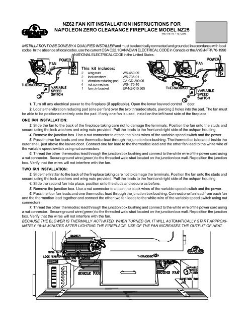
NZ62 FAN KIT INSTALLATION INSTRUCTIONS FORNAPOLEON ZERO CLEARANCE FIREPLACE MODEL NZ25WS-415-75 / 10.12.95INSTALLATION T O BE DONE BY A QUALIFIED INSTALLER and must be electrically connected and groun<strong>de</strong>d in accordance with localco<strong>de</strong>s. In the absence of local co<strong>de</strong>s, use the current CSA C22.1 CANADIAN ELECTRICAL CODE in Canada or the ANSI/NFPA 70-1990NATIONAL ELECTRICAL CODE in the United States.whiteb<strong>la</strong>ckThis kit inclu<strong>de</strong>s:2 wing nuts WS-450-092 lock washers WS-735-011 vibration reducing pad GA-GD-290.054 nut connectors WS-175-101 fan C/W bracket EP-NZ-010.365whiteb<strong>la</strong>ck1. Turn off any electrical power to the firep<strong>la</strong>ce (if applicable). Open the lower louvred control door.2. Locate the vibration reducing pad (one per fan) over the two threa<strong>de</strong>d studs, piercing 2 holes into the pad. The fan mustbe able to be positioned entirely onto the pad. If only one fan is used, install on the left hand si<strong>de</strong> of the firep<strong>la</strong>ce.ONE FAN INSTALLATION:3. Sli<strong>de</strong> the fan to the back of the firep<strong>la</strong>ce taking care not to damage the terminals. Position the fan onto the studs andsecure using the lock washers and wing nuts provi<strong>de</strong>d. Pull the leads to the front and right si<strong>de</strong> of the ashpan housing.4. Remove the junction box. Use a nut connector to attach the b<strong>la</strong>ck wires of the variable speed switch and the power.5. Pass the two fan leads and one thermodisc lead through the junction box bushing. The thermodisc is located insi<strong>de</strong> theouter shell, just above the louvre door. Connect one fan lead to the thermodisc lead and the other fan lead to the white wire ofthe variable speed switch using nut connectors.6. Thread the other thermodisc lead through the junction box bushing and connect to the white wire of the power cord usinga nut connector. Secure ground wire (green) to the threa<strong>de</strong>d weld stud located on the junction box wall. Reposition the junctionbox. Verify that the wires will not interfere with the fan.TWO FAN INSTALLATION:3. Sli<strong>de</strong> the first fan to the back of the firep<strong>la</strong>ce taking care not to damage the terminals. Position the fan onto the studs andsecure using the lock washers and wing nuts provi<strong>de</strong>d. Pull the leads to the front and right si<strong>de</strong> of the ashpan housing.4. Sli<strong>de</strong> the second fan into p<strong>la</strong>ce, position onto the studs and secure as before.5. Remove the junction box. Use a nut connector to attach the b<strong>la</strong>ck wires of the variable speed switch and the power.6. Pass the four fan leads and one thermodisc lead through the junction box bushing. Connect one fan lead from each fanand the thermodisc lead together and connect the other two fan leads to the white wire of the variable speed switch using nutconnectors.7. Thread the other thermodisc lead through the junction box bushing and connect to the white wire of the power cord usinga nut connector. Secure ground wire (green) to the threa<strong>de</strong>d weld stud located on the junction box wall. Reposition the junctionbox. Verify that the wires will not interfere with the fan.BECAUSE THE BLOWER IS THERMALLY ACTIVATED, WHEN TURNED ON, IT WILL AUTOMATICALLY START APPROXI-MATELY 15-45 MINUTES AFTER LIGHTING THE FIREPLACE. USE OF THE FAN INCREASES THE OUTPUT OF HEAT.