HD-P8000 CE.qxp - Ramsey Winch
HD-P8000 CE.qxp - Ramsey Winch
HD-P8000 CE.qxp - Ramsey Winch
- No tags were found...

Create successful ePaper yourself
Turn your PDF publications into a flip-book with our unique Google optimized e-Paper software.
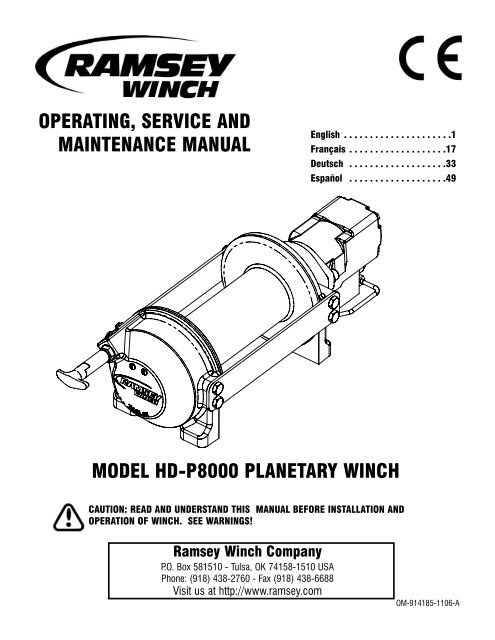
OPERATING, SERVI<strong>CE</strong> ANDMAINTENAN<strong>CE</strong> MANUALEnglish . . . . . . . . . . . . . . . . . . . . .1Français . . . . . . . . . . . . . . . . . . .17Deutsch . . . . . . . . . . . . . . . . . . .33Español . . . . . . . . . . . . . . . . . . .49MODEL <strong>HD</strong>-<strong>P8000</strong> PLANETARY WINCHCAUTION: READ AND UNDERSTAND THIS MANUAL BEFORE INSTALLATION ANDOPERATION OF WINCH. SEE WARNINGS!<strong>Ramsey</strong> <strong>Winch</strong> CompanyP.O. Box 581510 - Tulsa, OK 74158-1510 USAPhone: (918) 438-2760 - Fax (918) 438-6688Visit us at http://www.ramsey.comOM-914185-1106-A
TABLE OF CONTENTSINTRODUCTIONS . . . . . . . . . . . . . . . . . . . . . . . . . . . . . . . . . . . . . . . . . . . . . . . . . . . . . . . . . . . . . . . . . . . . . . .3WARRANTY INFORMATION . . . . . . . . . . . . . . . . . . . . . . . . . . . . . . . . . . . . . . . . . . . . . . . . . . . . . . . . . . . . . . .3SPECIFICATIONS . . . . . . . . . . . . . . . . . . . . . . . . . . . . . . . . . . . . . . . . . . . . . . . . . . . . . . . . . . . . . . . . . . . . . . .3WARNINGS . . . . . . . . . . . . . . . . . . . . . . . . . . . . . . . . . . . . . . . . . . . . . . . . . . . . . . . . . . . . . . . . . . . . . . . . . . .3WINCH MOUNTING . . . . . . . . . . . . . . . . . . . . . . . . . . . . . . . . . . . . . . . . . . . . . . . . . . . . . . . . . . . . . . . . . . . . .4CABLE INSTALLATION . . . . . . . . . . . . . . . . . . . . . . . . . . . . . . . . . . . . . . . . . . . . . . . . . . . . . . . . . . . . . . . . . . .4MAINTENAN<strong>CE</strong> . . . . . . . . . . . . . . . . . . . . . . . . . . . . . . . . . . . . . . . . . . . . . . . . . . . . . . . . . . . . . . . . . . . . . . . .5OPERATION . . . . . . . . . . . . . . . . . . . . . . . . . . . . . . . . . . . . . . . . . . . . . . . . . . . . . . . . . . . . . . . . . . . . . . . . . . .5HYDRAULIC SYSTEM REQUIREMENTS . . . . . . . . . . . . . . . . . . . . . . . . . . . . . . . . . . . . . . . . . . . . . . . . . . . . . .6TYPICAL LAYOUT . . . . . . . . . . . . . . . . . . . . . . . . . . . . . . . . . . . . . . . . . . . . . . . . . . . . . . . . . . . . . . . . . . . . . .6PERFORMAN<strong>CE</strong> CHARTS . . . . . . . . . . . . . . . . . . . . . . . . . . . . . . . . . . . . . . . . . . . . . . . . . . . . . . . . . . . . . . . . .6TROUBLE SHOOTING GUIDE . . . . . . . . . . . . . . . . . . . . . . . . . . . . . . . . . . . . . . . . . . . . . . . . . . . . . . . . . . . . . .7OVERHAUL INSTRUCTIONS . . . . . . . . . . . . . . . . . . . . . . . . . . . . . . . . . . . . . . . . . . . . . . . . . . . . . . . . . . . .8-10DIMENSIONAL DRAWINGS . . . . . . . . . . . . . . . . . . . . . . . . . . . . . . . . . . . . . . . . . . . . . . . . . . . . . . . . . . . . .11-2PARTS LIST AND PARTS DRAWINGS . . . . . . . . . . . . . . . . . . . . . . . . . . . . . . . . . . . . . . . . . . . . . . . . . . . .13-16LIMITED WARRANTYRAMSEY WINCH warrants each new RAMSEY <strong>Winch</strong> to be free from defects in material and workmanship for a period of one (1) yearfrom date of purchase.The obligation under this warranty, statutory or otherwise, is limited to the replacement or repair at the Manufacturer's factory, or at a pointdesignated by the Manufacturer, of such part that shall appear to the Manufacturer, upon inspection of such part, to have been defective inmaterial or workmanship.This warranty does not obligate RAMSEY WINCH to bear the cost of labor or transportation charges in connection with the replacement orrepair of defective parts, nor shall it apply to a product upon which repair or alterations have been made, unless authorized byManufacturer, or for equipment misused, neglected or which has not been installed correctly.RAMSEY WINCH shall in no event be liable for special or consequential damages. RAMSEY WINCH makes no warranty in respect toaccessories such as being subject to the warranties of their respective manufacturers.RAMSEY WINCH, whose policy is one of continuous improvement, reserves the right to improve its products through changes in design ormaterials, as it may deem desirable without being obligated to incorporate such changes in products of prior manufacture.If field service at the request of the Buyer is rendered and the fault is found not to be with RAMSEY WINCH's product, the Buyer shall paythe time and expense to the field representative. Bills for service, labor or other expenses that have been incurred by the Buyer withoutapproval or authorization by RAMSEY WINCH will not be accepted.See warranty card for details.
PLEASE READ THIS MANUAL CAREFULLYThis manual contains useful ideas for obtaining the most efficient operation from your <strong>Ramsey</strong> <strong>Winch</strong>, and safety proceduresone needs to know before operating a <strong>Ramsey</strong> <strong>Winch</strong>. Do not operate this winch until you have carefully read and understandthe "WARNING" and "OPERATION" sections of this manual.WARRANTY INFORMATION<strong>Ramsey</strong> <strong>Winch</strong>es are designed and built to exacting specifications. Great care and skill go into every winch we make. If theneed should arise, warranty procedure is outlined on the back of your self-addressed postage paid warranty card. Please readand fill out the enclosed warranty card and send it to <strong>Ramsey</strong> <strong>Winch</strong> Company. If you have any problems with your winch,please follow instructions for prompt service on all warranty claims. Refer to back page for limited warranty.SPECIFICATIONS*Rated Line Pull (lbs.) …………………………………………………… 8,000(Kg.) …………………………………………………… 3,620Gear Reduction …………………………………………………………… 5.1:1Weight (without cable) <strong>HD</strong>-<strong>P8000</strong> STD. ……..…....………. 82 lbs. (37.2 Kg)<strong>HD</strong>-<strong>P8000</strong> "Y" ………….………….. 76 lbs. (34.5 Kg)LAYER OF CABLE 1 2 3 4 5*Rated line pull lbs. 8,000 6,800 5,900 5,200 4,700per layer Kg. 3,620 3,080 2,670 2,350 2,120* Cable Capacity per Layer<strong>HD</strong>-<strong>P8000</strong> (STD.DRUM)<strong>HD</strong>-<strong>P8000</strong> ("Y"DRUM)* Line Speed (at15 GPM)ft. 25 55 90 130 170m 7 16 27 39 51ft. 15 35 60 85 115m 4 10 18 25 34FPM 50 58 67 76 84MPM 15.2 17.6 20.3 23.1 25.5* These specifications are based on recommended wire rope of 3/8" (10mm)galvanized aircraft cable, or EIPS cable and a 14.9 cu.in./Rev. motor.NOTE: The rated line pulls shown are for the winch only. Consult the wire rope manufacturer for wire rope ratings.WARNINGS:A MOTOR SPOOL (OPEN <strong>CE</strong>NTER) DIRECTIONAL CONTROL VALVE IS REQUIRED FOR BRAKE OPERATION.CLUTCH MUST BE FULLY ENGAGED BEFORE STARTING THE WINCH.DO NOT DISENGAGE CLUTCH UNDER LOAD.DO NOT LEAVE CLUTCH ENGAGED WHEN WINCH IS NOT IN USE.STAY OUT FROM UNDER AND AWAY FROM RAISED LOADS.STAND CLEAR OF CABLE WHILE PULLING. DO NOT TRY TO GUIDE CABLE.DO NOT EX<strong>CE</strong>ED MAXIMUM LINE PULL RATINGS SHOWN IN TABLE.DO NOT USE WINCH TO LIFT, SUPPORT, OR OTHERWISE TRANSPORT PERSONNEL.A MINIMUM OF 5 WRAPS OF CABLE AROUND THE DRUM BARREL IS NE<strong>CE</strong>SSARY TO HOLD THE LOAD. CABLE CLAMP(SETSCREW) IS NOT DESIGNED TO HOLD LOAD.IN CAR CARRIER APPLICATIONS, AFTER PULLING VEHICLE ON CARRIER, BE SURE TO SECURE VEHICLE TO CARRIERBED. DO NOT MAINTAIN LOAD ON WINCH CABLE WHILE TRANSPORTING VEHICLE. DO NOT USE WINCH AS A TIEDOWN.WHEN PULLING A HEAVY LOAD PLA<strong>CE</strong> A BLANKET, JACKET, OR TARPAULIN OVER THE CABLE FIVE OR SIX FEET FROMTHE HOOK.AVOID CONDITIONS WHERE LOAD SHIFTS OR JERKS OCCUR, AS THEY MAY INDICATE A DANGEROUS SITUATION.3
WINCH MOUNTINGESSENTIAL MOUNTING INSTRUCTIONS TO MAINTAIN ALIGNMENT OF PLANETARY WINCH COMPONENTS:It is most important that this winch be mounted securely sothat the three major sections (the motor end, the cabledrum, and the gear housing end) are properly aligned.Excessive bushing wear and difficulty in freespooling areusually symptoms of misalignment.In the as-installed condition, if the winch is mid-mounted,then at least one tie-plate must be attached to the mountingfeet at the bottom of the winch to maintain alignment. If thewinch is foot mounted then at least one tie-plate mustremain mounted at midpoint of winch to maintain alignment.It is always preferred to used BOTH tie-plates in the finalinstalled configuration.Angle Mounting Kit, P/N 251006 (for Std. Drum) or 251007(for “Y” drum), is recommended for maximum ease inmounting the winch. The angle kit will allow the winch to bemounted in upright or midmount applications and will meetthe criteria of serving as a solid and true mounting surface.When mounting the winch with other than the recommended<strong>Ramsey</strong> Angle Kit, the mounting hole patterns described inthe Dimensional drawings on pages 14-15 should be used.The mounting surface must be flat within .015 inch and sufficientlystiff to resist flexing. If a steel plate is used for footmounting, it should be .750 inch thick. For this mountingMID MOUNTTIEPLATE AT FOOT (BASE) LOCATIONapplication eight (8) 1/2-13NC x 1-1/2” long grade 5 capscrews with lockwashers will be needed to mount winch. Capscrews should betightened to 85 ft-lb (115 Nm) torque.NOTE: If angles or a steel plate are used in mounting winch, tie-plates provided with winch are to be attached to the remaining mountingpads, whether they be side or foot.CABLE INSTALLATIONAn “A” or “B” decal on the clutch end bearing indicates the spooling direction of the cable. Also, a letter “A” or “B” is stamped in the endbearing on the clutch end indicating rotation direction. If the decal is damaged or unreadable, contact Customer Service for additionalinstructions to determine proper direction. To reverse the rotation direction, exchange positions of the cartridge and plug shown atright.1. Unwind cable by rolling it out along theground to prevent kinking. Securelywrap end of cable, opposite hook, withplastic or similar tape to prevent fraying.2. Place taped end of cable into hole incable drum as shown below. Use the3/8-16NC x 1/2” long hex socket drivesetscrew (included with drum assemblyitem #1) to secure cable to drum.3. Carefully run winch in the "reel-in" direction.Keeping tension on end of cable,spool all the cable onto the cable drum,taking care to form neatly wrapped layers.After installing cable, check freespool operation.Disengage clutch and pull on cable at awalking speed. If cable “birdnests”, loosenjam nut (item #20) and turn nylon setscrew(item #17) clockwise to increase drag onCAUTION: If longer bolts (minimum grade 5) are substituted to mount winch or tomount a roller guide at the side mount pads, bolt length must be such as to allow aminimum of .50 inch thread length engagement in the tapped holes in side of eachend bearing. Use of excessive length bolts will damage the winch and preventfreespool of the drum. Torque bolts to 55 ft-lbs. (75 Nm).MOTOR ENDFOOT MOUNTINSERT CABLE AS SHOWN FOR "A" ROTATIONOVERWOUND APPLICATION.(UNDERWOUND APPLICATION REQUIRES CABLE TOCOME UNDER DRUM FROM OPPOSITE DIRECTIONAND INSERTED IN THIS SAME CABLE POCKET.)"A" ROTATIONDIRECTIONSETSCREWCABLE DRUMTIEPLATE AT SIDE LOCATION"B" ROTATIONDIRECTIONGEAR HOUSING ENDINSERT CABLE AS SHOWN FOR "B" ROTATIONOVERWOUND APPLICATION.(UNDERWOUND APPLICATION REQUIRES CABLE TOCOME UNDER DRUM FROM OPPOSITE DIRECTIONAND INSERTED IN THIS SAME CABLE POCKET.)drum. If cable pull is excessive, loosen nylon setscrew by turning counterclockwise. Tighten jam nut when proper setting is obtained.CAUTION: OVER-TIGHTENING OF JAM NUT MAY STRIP NYLON SETSCREW.42017
CABLE DRUMROTATION DIRECTIONCABLE DRUMROTATION DIRECTIONCARTRIDGEPOSITIONMAINTENAN<strong>CE</strong>"A" ROTATIONPLUGPOSITION(REEL IN) RAISE INLET"B" ROTATIONCARTRIDGEPOSITION1. Inspect the cable for damage and lubricate frequently. If the cable becomes frayed with broken strands, replace immediately. Cable andhook assembly (100’ long cable) P/N 524118 (“Y” drum) or (150’ long cable) P/N 524119 (STD drum) may be purchased from a<strong>Ramsey</strong> distributor.2. Check that the clutch is fully engaging. See OPERATION instructions, above, for the appropriate clutch shifter. FOR MANUAL CLUTCHONLY: Monthly, disengage clutch, put several drops of oil on the clutch handle shaft and work clutch handle IN and OUT several timesto lubricate inside the shifter assembly.3. Check to see that the drum cable does not overrun (“birdnest”) when freespooling. Refer to page 4 if it does.4. Replace drum bushings and seals if seals begin to seep grease. Refer to the Overhaul Instructions, pages 8-10. Add additional lubricant,Mobilith SHC 007, to gears and drum bearings if required.OPERATIONThe best way to get acquainted with how your winch operates is to make test runs before you actually use it. Plan your test in advance.Remember, you hear your winch as well as see it operate. Get to recognize the sounds of a light steady pull, a heavy pull, and soundscaused by load jerking or shifting. Avoid conditions where load shifts or jerks occur, as they may indicate a dangerous situation.The uneven spooling of cable, while pulling the load, is not a problem, unless there is a cable pileup on one end of the drum. If this happens,reverse the winch to relieve the load, and move your anchor point further to the center of the vehicle. After the job is done you can unspooland rewind for a neat lay of the cable.When pulling a heavy load, place a blanket, jacket, and tarpaulin over the cable about five or six feet behind the hook. In the event of a brokencable, this will slow the snap back of the cable and could prevent serious injury.The winch clutch allows rapid unspooling of the cable, from the cable drum, for hooking onto the load. The clutch is operated by the clutchshifter lever or air shifter.WARNING: DO NOT DISENGAGE CLUTCH UNDER LOAD!MANUAL CLUTCH SHIFTER (Refer to dimensional drawing page 11):TO DISENGAGE CLUTCH: Run the winch in the reverse (reel out) direction until the load is off the cable. Pull handle out and rotate 90°. Withhandle in the “DISENGAGED” position, cable may now be free-spooled from the drum.TO ENGAGE CLUTCH: Pull handle out, rotate 90° and release handle. Run the winch in reverse until the clutch handle snaps fully into the“ENGAGED” position. DO NOT attempt to pull a load unless the handle is fully at the “ENGAGED” position. If manual shift indicator light ispresent, the green light is lit when clutch is fully “ENGAGED”. DO NOT attempt to pull a load unless the green light is lit. To install light to thevehicle electrical system refer to the Electrical Schematic on page 12.AIR CYLINDER CLUTCH SHIFTER (Refer to the dimensional drawing page 12):TO DISENGAGE CLUTCH: Run the winch in the reverse (reel out) direction until load is off the cable. Apply air pressure to the .125-27 NPTport: 80 PSI (min.)-150 PSI (max.). CAUTION: PRESSURE MUST NOT EX<strong>CE</strong>ED 150 PSI.TO ENGAGE CLUTCH: Remove air pressure from the cylinder (a return spring engages the plunger). Run winch in reverse until the clutchengagement indicator light (green light) is lit. To install light to the vehicle electrical system refer to the Electrical Schematic on page 12.5
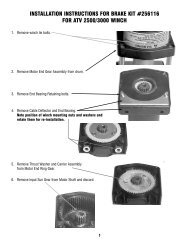
INSTRUCTIONS FOR OVERHAUL <strong>HD</strong>-<strong>P8000</strong> SERIES WINCHTake note of mounting configurations for proper mounting of parts during re-assembly. Replace all gaskets, o-rings,and seals during re-assembly.Disconnect tube (item #41) from elbow fittings (items #24)on bottom of end bearing and counterbalance valve (item#42). Remove motor (item #27) from end bearing by slowlyunscrewing capscrews (items #18). CAUTION: MOTOR ISUNDER SPRING PRESSURE.Check breather vent (item #45). Make sure it is not clogged.If oil is leaking from vent, check brake o-rings, backup rings,and sealing surfaces (see page 8).Remove springs (items #40) from pockets and inspect fordamage.Replace gasket (item #25).Remove coupling (item #23) from end bearing. Examine couplingfor signs of wear, replace if necessary. If necessary,remove counterbalance valve from motor by removing capscrews(items #14).1822272441 42 2114242523404539Remove retaining rings (items #39) with screwdriver.Remove brake parts from end bearing. NOTE POSITION OF O-RINGS AND BACKUP RINGS BEFORE REMOVAL. Examinebrake discs (items #4) and stators (items #3) for signs ofwear, and replace if necessary.Examine o-rings (items #28 and 29) and backup rings (items#31 and 33) in brake piston (item #5), as well as o-ring (item#30) and backup ring (item #32) in backup brake piston(item #6) for signs of wear. Remove o-rings and backup ringsfrom grooves in brake piston or backup brake piston andreplace if necessary.5312833293032634Remove tie plates (items #11) from end bearings byunscrewing capscrews (items #15). Slide motor endbearing (item #8) and drum (item #1) from gear housingend bearing.Remove input shaft (item #10) from end bearing. Inspectshaft and and output sun gear (item #7) for damage andreplace if necessary. To remove the output sun gear,remove the snap rings (items #38) and thrust washer(item #44) and pull off the end of the shaft.Remove bushing (item #13) and o-ring (item #34) frommotor end bearing. Place new, well-oiled o-ring intogroove inside of end bearing and press new bushing ontoend bearing.1511813341111510387448
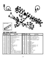
Remove seal (item #37) from gear housing end bearing (item #9). Loosen nut(item #20) and remove nylon setscrew (item #17). Remove ring gear fromgear housing end bearing, if necessary. Remove bushing (item #12) from endbearing.Press new bushing into end bearing. Install ring gear, then nylon setscrew andnut. Ring gear must be fully seated in end bearing and slot in ring gear MUSTNOT be aligned with clutch shifter hole. Install new seal in end bearing, withsharp edge of seal outward.372612 9Generously apply grease (MOBILITH SHC 007) to teeth of ring gear (item #26),20teeth of planet gears in drum (item #1), and to bushing (item #12) in gearhousing end bearing. Apply a small amount of grease to base of bushing (item#13) on motor end bearing. Apply grease to teeth of output sun gear (item #7) and input shaft (item #10).Place end of shaft with output sun gear on it into drum (item #2). Rotate shaft to engage planet gears with output sun gear.Place Gear End Bearing on Drum and engage planet gears with ring gear.Assemble motor end bearing (item #8) to drum assembly and use tie plates (items #11) and capscrews (items #15) to holdboth end bearings together. Tighten capscrews to 55 ft-lbs (75 Nm).17If necessary, remove and replace the shifter assembly (manual, item #2, or air-cylinder, item #3), as follows:MANUAL CLUTCH SHIFTER ASSEMBLYLoosen setscrew (item #19) and jam nut, then unscrew shifter assembly (item #2). Be sure slot in ring gear is not aligned withclutch shifter hole. Rotate drum, if necessary, to ensure hole and slot are not aligned.Reinstall shifter assembly with plunger, jam nut, and handle positioned in gear housing as shown below. Thread assembly (withhandle engaged in cylinder slot) into the gear housing. Pull drum toward the gear end bearing housing to remove play. Holddrum in position and continue threading the shifter assembly in until the gap between the end of the handle and cylinder is7/16 +0 -1/16 inch and handle is in the horizontal position (see below). Note: This gap will vary with drum endplay. With thedrum pulled against the motor end housing, the gap should be 3/8 inch.Lightly tighten jam nut. Rotate drum until handle snaps fully into the engaged position. Pull handle out and rotate 90°. Verify thatdrum can be rotated freely (at least one full revolution)with clutch shifter at the DISENGAGED39position. Securely tighten jam nut while holding LIGHT SWITCH454the handle. Tighten setscrew (item #19) securely.Re-check clutch operation as described on9382LIGHT ASSEMBLYpage 5.AIR CYLINDER SHIFTER ASSEMBLYLoosen set screw (item #19) to remove shifter1616assembly (item #3). To reinstall, place 1 or 219shims (items #41) over plunger and threadHANDLE (HORIZONTAL)shifter assembly into gear end housing. Add orremove shims to orient ports for pneumatic connections.Ports should point down (below horizontal).Tighten setscrew. Check for clutch oper-CYLINDERation as described on page 5.2If the light assembly (item #2) or light switch(item #45) needs to be replaced, refer to theschematic on page 12 for electrical connectionsand disassemble and reassemble as shown.419PLUNGER3JAM NUTAIR-CYLINDERCLUTCH SHIFTERMANUAL CLUTCHSHIFTERMANUAL CLUTCH ADJUSTMENT
Set winch with gear housing end down on work surface.Install well-oiled o-rings and backup rings into grooves on outside of brake piston and backup brake piston as shown in crosssectionA-A below.Piston, backup piston, brake discs and stators must be clean and free of grease and oil.Insert brake discs (item #4) and stators (item #3) into gear end alternating, with stators first and last.Insert backup brake piston (item #6) into motor end and insert brake piston (item #5) into it. Apply even pressure on pistonwhen installing.Install retaining rings (item #39) into grooves in motor end housing.MOTOR SIDE3129303239A33531283329303264A5SECTION A-A628DRUM SIDE3Insert springs (item #40) into pockets in back of brake piston.The two empty pockets should be on opposite sides.Install roll pin (item #35) into new motor coupling belowbottom of spline teeth. Insert motor coupling (item #23),engaging it with the discs and the input shaft.18Place gasket (item #25) on mounting surfaceof motor (item #27). Slide motor shaft intocoupling. Attach motor to motor end bearinghousing using (2) capscrews (item #18) and(2) lockwashers (item #22). Evenly tighten to49 ft-lbs. (66 Nm) torque.24Install the counterbalance valve (item #42) tothe motor using (4) capscrews (item #14)and (4) lockwashers (item #21). Tighten to17 ft-lbs (23 Nm).Securely connect fittings (item #24) to motorend housing and counterbalance valve, andconnect tube assembly (item #41) to fittings.Apply at least 550 PSI hydraulic system pressureto brake and verify that brake releases(winch drum will rotate).41 42 2114222735242523404510
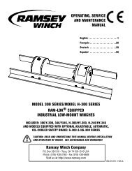
CLUTCH DISENGAGED POSITIONCLUTCH ENGAGED POSITIONFOR SIDE MOUNT INSTALLATIONS,MOVE TIE PLATES TO FEET1/2-13UNC X .75 (INCHES) DEEP TAPPED HOLE(2-PLA<strong>CE</strong>S EACH SIDE OF MOTOR END BEARING)1.25[31.7] A7.17.50[182.1][12.7]Ø.50[Ø12.7]CABLEANCHORØ8.25FLANGEDRUM[209.6] .56[14.3](TYP)8.38[212.9]2.21[56.1]4.68[118.9]2.21[56.1]9.36[237.7]3.79[96.3]4.25[108.0]1.12[28.4](TYP)8.46[214.9]7/8-14 SAE PORT(2-PLA<strong>CE</strong>S)4.92[125.0]DBFØ3.94[100.0]BARREL<strong>CE</strong>1/2-13UNC X .50 (INCHES) DEEP TAPPED HOLE(2-PLA<strong>CE</strong>S EACH SIDE OF GEAR HOUSING END BEARING)4.19[106.4]8.38[212.7]2.25[57.2](TYP)1.12[28.4](TYP)1/2-13UNC X .75 (INCHES) DEEP TAPPED HOLE(4-PLA<strong>CE</strong>S EACH END BEARING)NOTES:1. DIMENSIONS SHOWN ARE INCHES OVER MILLIMETERS.2. WINCH MOUNTING CAPSCREWS MUST MEET OR EX<strong>CE</strong>ED SAE GRADE 5 SPECIFICATION.3. THESE HOLE LOCATIONS MUST BE HELD WITHIN ±.03 (0.8mm)OF TRUE POSITION. RECOMMENDED MOUNTING HOLE DIAMETER IS .53 (13.5mm).4. "A" ROTATION SHOWN.WINCHMODEL<strong>HD</strong>-<strong>P8000</strong>STD. DRUM<strong>HD</strong>-<strong>P8000</strong>"Y" DRUMAINCHESMM9.75247,76.50165,1BINCHESMM12.25311,29.00228,6CINCHESMM8.87225,37.24184,0DINCHESMM14.60370,912.98329,6EINCHESMM13.28337,411.66296,2FINCHESMM27.89708,324.64625.8<strong>HD</strong>-<strong>P8000</strong> MANUAL SHIFT11
3.79[96.3]1/8-27NPT PORT(CONNECT 80 TO 150 PSI**PRESSURE LINE TO DISENGAGE CLUTCH)ATTACH TO GROUND (-)(SEE ELECTRICAL SCHEMATIC)ATTACH TO 12V DC (+)(SEE ELECTRICAL SCHEMATIC)FOR SIDE MOUNT INSTALLATIONS,MOVE TIE PLATES TO FEET1/2-13UNC X .75 (INCHES) DEEP TAPPED HOLE(2-PLA<strong>CE</strong>S EACH SIDE OF MOTOR END BEARING)1.25[31.7]Ø8.25[209.6]FLANGEADRUMØ.50[Ø12.7]CABLEANCHOR3.56[90.5]8.38[212.9]2.21[56.1]2.21[56.1]4.68[118.9]9.36[237.7]SWITCHINDICATORLIGHT.56[14.3](TYP)4.25[108.0]1.12[28.4](TYP)8.46[214.9]4.92[125.0]7/8-14 SAE PORT(2-PLA<strong>CE</strong>S)DBFØ3.94[100.0]BARREL<strong>CE</strong>1/2-13UNC X .50 (INCHES) DEEP TAPPED HOLE(2-PLA<strong>CE</strong>S EACH SIDE OF GEAR HOUSING END BEARING)4.19[106.4]8.38[212.7]2.25[57.2](TYP)1.12[28.4](TYP)1/2-13UNC X .75 (INCHES) DEEP TAPPED HOLE(4-PLA<strong>CE</strong>S EACH END BEARING)NOTES:1. DIMENSIONS SHOWN ARE INCHES OVER MILLIMETERS.2. WINCH MOUNTING CAPSCREWS MUST MEET OR EX<strong>CE</strong>ED SAE GRADE 5 SPECIFICATION.3. THESE HOLE LOCATIONS MUST BE HELD WITHIN ±.03 (0.8mm)OF TRUE POSITION. RECOMMENDED MOUNTING HOLE DIAMETER IS .53 (13.5mm).4. CAUTION: PRESSURE MUST NOT EX<strong>CE</strong>ED 150 PSI.5. "A" ROTATION SHOWN.ATTACH TO GROUND (16 GA.WIRE SUPPLIED BY CUSTOMER)12V BATTERYATTACH TO PTO INDICATOR SWITCH TORE<strong>CE</strong>IVE 12V DC WHEN PTO IS ENGAGED.BUTTCONNECTORSWITCHNOTE: LIGHT SHOULD BE "ON" WHEN CLUTCH ISENGAGED AND "OFF" WHEN CLUTCH IS DISENGAGED.INDICATOR LIGHT(ON WHEN CLUTCHIS ENGAGED)ELECTRICALSCHEMATICWINCHMODEL<strong>HD</strong>-<strong>P8000</strong>STD. DRUMAINCHESMM9.75247,7BINCHESMM12.25311,2CINCHESMM8.87225,3DINCHESMM14.60370,9EINCHESMM12.72323,1FINCHESMM27.31693,7<strong>HD</strong>-<strong>P8000</strong> 6.50 9.00 7.24 12.98 9.47 24.06"Y" DRUM 165,1 228,6 184,0 329,6 240,6 611,1<strong>HD</strong>-<strong>P8000</strong> AIR SHIFT12
41241842222725352114233954031303261341210241538874511441317203437192636943152161128332913
PARTS LIST - MANUAL SHIFTItem No. Quantity Part No. Description Item No. Quantity Part No. Description1 1 234205 DRUM ASSY STD 23 1 431019 COUPLING-MOTOR1 234204 DRUM ASSY "Y" 24 2 432018 FITTING2 1 276048 SHIFTER ASSY 25 1 442223 GASKET-MOTOR FLANGE3 6 330011 STATOR-BRAKE 26 1 444084 GEAR-RING4 5 330012 DISC-BRAKE 27 1 458074 MOTOR-HYD.5 1 330013 PISTON-BRAKE 28 1 462067 O-RING PISTON-SM.6 1 330014 PISTON-BACKUP BRAKE 29 1 462068 O-RING PISTON-LG.7 1 334174 GEAR-OUTPUT, SUN 30 1 462069 O-RING BACKUP PISTON8 1 338358 END BEARING-MOTOR 31 1 462070 RING-BACKUP PISTON-LG9 1 338359 END BEARING-GEAR HOUSING 32 1 462071 RING-BACKUP BACKUP PISTON10 1 357177 SHAFT-INPUT STD DRUM 33 1 462072 RING-BACKUP PISTON-SM1 357176 SHAFT-INPUT "Y" DRUM 34 1 462073 O-RING11 2 395427 PLATE-TIE STD DRUM 35 1 470033 SPIROL PIN2 395426 PLATE-TIE "Y" DRUM 36 1 472052 PLUG12 1 412085 BUSHING-DRUM 37 1 486080 SEAL13 1 412109 BUSHING-DRUM, MOTOR END 38 2 490003 SNAP RING14 4 414159 CAPSCREW-5/16-18UNC X 2 1/2", HEX HEAD, ZINC, GR5 39 2 490049 RING-INTERNAL RETAINING15 8 414581 CAPSCREW-1/2-13NC X 3/4", HEX HEAD, ZINC, GR5 40 9 494124 SPRING-BRAKE16 2 414854 SCREW-1/4-20NC X 1/2", ROUND HEAD, SLOTTED, ZINC 41 1 509132 TUBE-BRAKE RELEASE (PORTS DOWN)17 1 414926 SETSCREW-3/8-16NC X 1", SOCKET HEAD, NYLON 1 509131 TUBE-BRAKE RELEASE (PORTS UP)18 2 414952 CAPSCREW-1/2-13NC X 1 1/2", SOCKET HEAD, ZINC 42 1 516041 VALVE-MOTOR CONTROL (A ROTATION)19 1 416016 SETSCREW-1/4-20NC X 1/4", HEX SOCKET HEAD CUP 1 516042 VALVE-MOTOR CONTROL (B ROTATION)20 1 418036 NUT-3/8-16 NC, HEX JAM, ZINC 43 1 518037 THRUST WASHER21 4 418163 LOCKWASHER-5/16 MED SECT, ZINC 44 1 518047 THRUST WASHER22 2 418218 LOCKWASHER-1/2 ID MED SECT, ZINC 45 1 456038 BREATHER VENT14
242441114124842928401813453821221918131536653432830 35 31337444325273729242047231716439234111104915
PARTS LIST - AIR SHIFTItem No. Quantity Part No. Description Item No. Quantity Part No. Description1 1 234205 DRUM ASSY STD 25 1 431019 COUPLING-MOTOR1 234204 DRUM ASSY "Y" 26 2 432018 FITTING2 1 236020 LIGHT ASSY 27 1 442223 GASKET-MOTOR FLANGE3 1 276058 SHIFTER ASSY 28 1 444084 GEAR-RING4 1 312529 BRACKET - LIGHT ASSY 29 1 458074 MOTOR-HYD.5 6 330011 STATOR-BRAKE 30 1 462067 O-RING PISTON-SM.6 5 330012 DISC-BRAKE 31 1 462068 O-RING PISTON-LG7 1 330013 PISTON-BRAKE 32 1 462069 O-RING BACKUP PISTON8 1 330014 PISTON-BACKUP BRAKE 33 1 462070 RING-BACKUP PISTON-LG9 1 334174 GEAR-OUTPUT, SUN 34 1 462071 RING-BACKUP BACKUP PISTON10 1 338358 END BEARING-MOTOR 35 1 462072 RING-BACKUP PISTON-SM11 1 338359 END BEARING-GEAR HOUSING 36 1 462073 O-RING12 1 357177 SHAFT-INPUT STD DRUM 37 1 470033 SPIROL PIN1 357176 SHAFT-INPUT "Y" DRUM 38 1 482013 RUBBER BOOT13 2 395427 PLATE-TIE STD DRUM 39 1 482045 RUBBER BOOT2 395426 PLATE-TIE "Y" DRUM 40 1 486080 SEAL14 1 412085 BUSHING-DRUM 41 2 488007 SHIM15 1 412109 BUSHING-DRUM, MOTOR END 42 2 490003 SNAP RING16 2 414036 CAPSCREW-1/4-20NC X 1/2", HEX HEAD, ZINC 43 2 490049 RING-INTERNAL RETAINING17 4 414159 CAPSCREW-5/16-18UNC X 2 1/2", HEX HEAD, ZINC, GR5 44 9 494124 SPRING-BRAKE18 8 414581 CAPSCREW-1/2-13NC X 3/4", HEX HEAD, ZINC, GR5 45 1 504021 SWITCH19 1 414926 SETSCREW-3/8-16NC X 1", SOCKET HEAD, NYLON 46 1 509132 TUBE-BRAKE RELEASE (PORTS DOWN)20 2 414952 CAPSCREW-1/2-13NC X 1 1/2", SOCKET HEAD, ZINC 1 509131 TUBE-BRAKE RELEASE (PORTS UP)21 1 416016 SETSCREW-1/4-20NC X 1/4" HEX SOCKET HEAD CUP 47 1 516041 VALVE-MOTOR CONTROL A ROTATION22 1 418036 NUT-3/8-16 NC, HEX JAM, ZINC 1 516042 VALVE-MOTOR CONTROL B ROTATION23 4 418163 LOCKWASHER-5/16 MED SECT, ZINC 48 1 518047 THRUST WASHER24 2 418218 LOCKWASHER-1/2 ID MED SECT, ZINC 49 1 456038 BREATHER VENT16
MANUEL D’UTILISATION,DE DÉPANNAGEET D’ENTRETIENTREUIL À PLANÉTAIRE MODÈLE <strong>HD</strong>-<strong>P8000</strong>MISE EN GARDE : ASSUREZ-VOUS DE LIRE ET DE COMPRENDRE <strong>CE</strong> MANUEL AVANT D’INSTALLERET D’UTILISER LE TREUIL. N’OUBLIEZ PAS LES AVERTISSEMENTS ET MISES EN GARDE.<strong>Ramsey</strong> <strong>Winch</strong> CompanyP.O. Box 581510 - Tulsa, OK 74158-1510 USAPhone: (918) 438-2760 - Fax (918) 438-6688Visit us at http://www.ramsey.com
TABLE OF CONTENTSINTRODUCTIONS . . . . . . . . . . . . . . . . . . . . . . . . . . . . . . . . . . . . . . . . . . . . . . . . . . . . . . . . . . . . . . . . . . . . . .19INFORMATIONS DE GARANTIE . . . . . . . . . . . . . . . . . . . . . . . . . . . . . . . . . . . . . . . . . . . . . . . . . . . . . . . . . . .19CARACTÉRISTIQUES TECHNIQUES . . . . . . . . . . . . . . . . . . . . . . . . . . . . . . . . . . . . . . . . . . . . . . . . . . . . . . . .19AVERTISSEMENTS . . . . . . . . . . . . . . . . . . . . . . . . . . . . . . . . . . . . . . . . . . . . . . . . . . . . . . . . . . . . . . . . . . . .19FIXATION DU TREUIL . . . . . . . . . . . . . . . . . . . . . . . . . . . . . . . . . . . . . . . . . . . . . . . . . . . . . . . . . . . . . . . . . . .20INSTALLATION DU CÂBLE . . . . . . . . . . . . . . . . . . . . . . . . . . . . . . . . . . . . . . . . . . . . . . . . . . . . . . . . . . . . . . .20ENTRETIEN DU TREUIL . . . . . . . . . . . . . . . . . . . . . . . . . . . . . . . . . . . . . . . . . . . . . . . . . . . . . . . . . . . . . . . . .21TECHNIQUES D’UTILISATION . . . . . . . . . . . . . . . . . . . . . . . . . . . . . . . . . . . . . . . . . . . . . . . . . . . . . . . . . . . . .21SYSTÈMES HYDRAULIQUES . . . . . . . . . . . . . . . . . . . . . . . . . . . . . . . . . . . . . . . . . . . . . . . . . . . . . . . . . . . . .22DISPOSITION TYPE . . . . . . . . . . . . . . . . . . . . . . . . . . . . . . . . . . . . . . . . . . . . . . . . . . . . . . . . . . . . . . . . . . . .22GRAPHIQUES DE PERFORMAN<strong>CE</strong>S . . . . . . . . . . . . . . . . . . . . . . . . . . . . . . . . . . . . . . . . . . . . . . . . . . . . . . . .22GUIDE DE RÉSOLUTION DES PROBLÈMES . . . . . . . . . . . . . . . . . . . . . . . . . . . . . . . . . . . . . . . . . . . . . . . . . .23INSTRUCTIONS DE RÉVISION DES TREUILS . . . . . . . . . . . . . . . . . . . . . . . . . . . . . . . . . . . . . . . . . . . . . .24-26PLAN COTÉ . . . . . . . . . . . . . . . . . . . . . . . . . . . . . . . . . . . . . . . . . . . . . . . . . . . . . . . . . . . . . . . . . . . . . . .27-28LISTE ET SCHÉMA DES PIÈ<strong>CE</strong>S . . . . . . . . . . . . . . . . . . . . . . . . . . . . . . . . . . . . . . . . . . . . . . . . . . . . . . . .29-32GARANTIE LIMITÉERAMSEY WINCH garantit chaque treuil RAMSEY neuf contre tout défaut de matériau et de fabrication pendant une période d’un (1) an àpartir de la date d’achat. L'obligation aux termes de cette garantie, statutaire ou autre, est limitée au remplacement ou à la réparation à l’usinedu fabricant, ou à un endroit désigné par le fabricant, de la pièce qui semblera présenter un défaut de fabrication ou de matériau, suiteà l'inspection effectuée par le fabricant.Cette garantie n’oblige pas RAMSEY WINCH à s’acquitter des frais de main-d'ouvre ou de transport liés au remplacement ou à la réparationdes pièces défectueuses, et ne s'applique pas à un produit ayant subi des réparations ou des modifications (sauf si elles ont étéautorisées par le fabricant), ou en cas de mauvaise utilisation de l’équipement, de négligence ou de matériel mal installé.RAMSEY WINCH ne pourra en aucun cas être tenue responsable des dommages particuliers et indirects. RAMSEY WINCH n’émet aucunegarantie au sujet des accessoires et portant par exemple sur les garanties de leurs fabricants respectifs. RAMSEY WINCH s’efforce depoursuivre une politique d’amélioration constante et se réserve par conséquent le droit d'améliorer ses produits par le biais de modificationsde leur conception ou des matériaux employés, selon les besoins, et sans être obligée d'incorporer ces modifications aux produitsfabriqués précédemment.En cas d’intervention sur le terrain à la demande de l’acquéreur, et si la défaillance s’avère ne pas provenir du produit RAMSEY WINCH,l’acquéreur s’engage à s’acquitter auprès du représentant des frais correspondant au temps et aux dépenses.Les factures d'entretien, de main-d’ouvre et autres frais engagés par l’acquéreur sans l'accord ou l'autorisation de RAMSEY WINCH neseront pas acceptées.Reportez-vous à la carte de garantie pour les détails.
VEUILLEZ LIRE ATTENTIVEMENT <strong>CE</strong> MANUEL.Ce manuel contient des conseils utiles pour l'utilisation efficace de votre treuil <strong>Ramsey</strong> ; il aborde aussi les procédures de sécuritéà connaître absolument avant l’utilisation d’un tel équipement.INFORMATIONS DE GARANTIELes treuils <strong>Ramsey</strong> sont conçus et fabriqués selon des spécifications rigoureuses. Ils font tous l’objet d’un travail soigné etcompétent. En cas de besoin, la procédure de recours en garantie est détaillée au verso de votre carte de garantie préadresséeà port payé. Veuillez lire et remplir la carte de garantie ci-jointe, et l'envoyer à <strong>Ramsey</strong> <strong>Winch</strong> Company. En cas de problèmeavec votre treuil, suivez les instructions fournies afin d’obtenir un service rapide de recours en garantie.*CARACTÉRISTIQUES TECHNIQUESRemarque : les tractions nominales indiquées sont uniquement pour le treuil. Consultez le fabricant du câble pour les caractéristiques nominalesde ce dernier.AVERTISSEMENTS :Traction du câble (lbs.) …………………………………………………… 8,000nominale(Kg.) …………………………………………………… 3,620Démultiplication …………………………………………………………… 5.1:1Poids (sans le câble) <strong>HD</strong>-<strong>P8000</strong> STD. ……..…....………. 82 lbs. (37.2 Kg)<strong>HD</strong>-<strong>P8000</strong> "Y" ………….………….. 76 lbs. (34.5 Kg)Couche de câble1 2 3 4 5*Traction Nominale lbs. 8,000 6,800 5,900 5,200 4,700Par Couche De Câble Kg. 3,620 3,080 2,670 2,350 2,120* Capacité De Câble Par Couche<strong>HD</strong>-<strong>P8000</strong> (STD.DRUM)<strong>HD</strong>-<strong>P8000</strong> ("Y"DRUM)* Vitesse du câble(à 56 l/min)ft. 25 55 90 130 170m 7 16 27 39 51ft. 15 35 60 85 115m 4 10 18 25 34FPM 50 58 67 76 84MPM 15.2 17.6 20.3 23.1 25.5*Ces caractéristiques techniques sont basées sur un câble d’aéronef galvanisé de10 mm ou sur un câble en acier de charrue amélioré et sur un moteur de 254cm³/tr.UN DISTRIBUTEUR À TIROIR CYLINDRIQUE DE MOTEUR (<strong>CE</strong>NTRE OUVERT) EST NÉ<strong>CE</strong>SSAIRE POUR LE FONCTION-NEMENT DU FREIN.L’EMBRAYAGE DOIT ÊTRE ENTIÈREMENT ENCLENCHÉ AVANT DE COMMEN<strong>CE</strong>R TOUT TREUILLAGE.NE RELÂCHEZ JAMAIS L’EMBRAYAGE EN PRÉSEN<strong>CE</strong> D’UNE CHARGE.NE LAISSEZ PAS L’EMBRAYAGE ENCLENCHÉ LORSQUE LE TREUIL N’EST PAS UTILISÉ.NE VOUS PLA<strong>CE</strong>Z JAMAIS SOUS UNE CHARGE SOULEVÉE NI À PROXIMITÉ.RESTEZ À L’ÉCART DU CÂBLE LORS DU TREUILLAGE. N’ESSAYEZ PAS DE GUIDER LE CÂBLE.NE DÉPASSEZ PAS LES CARACTÉRISTIQUES DE TRACTION NOMINALES MAXIMALES INDIQUÉES DANS LE TABLEAU.N’UTILISEZ PAS LE TREUIL POUR SOULEVER, MAINTENIR OU TRANSPORTER DES PERSONNES.IL CONVIENT DE CONSERVER AU MINIMUM CINQ TOURS DE CÂBLE AUTOUR DU TAMBOUR POUR MAINTENIR LACHARGE. L’ATTACHE DU CÂBLE N’EST PAS CONÇUE POUR ASSURER LE MAINTIEN D’UNE CHARGE.DANS LES APPLICATIONS DE TRANSPORT D’AUTOMOBILES, VEILLEZ À BIEN FIXER LE VÉHICULE SUR LE PORTE-VOITURES. LA CHARGE IMPOSÉE AU CÂBLE DU TREUIL NE DOIT PAS ÊTRE MAINTENUE PENDANT LE TRANSPORT. N’U-TILISEZ PAS LE TREUIL COMME DISPOSITIF D’ATTACHE.LORSQUE VOUS TREUILLEZ UNE LOURDE CHARGE, PLA<strong>CE</strong>Z UNE COUVERTURE, UNE VESTE OU UNE BÂCHE SUR LECÂBLE À ENVIRON 1,8 m DU CROCHET.ÉVITEZ TOUS RISQUES DE GLISSEMENT DE LA CHARGE OU D’À-COUPS À SON NIVEAU, CAR ILS POURRAIENTS’AVÉRER DANGEREUX.19
FIXATION DU TREUILINSTRUCTIONS DE MONTAGE IMPORTANTES POUR MAINTENIR L’ALIGNEMENT DES ÉLÉMENTS DU TREUIL À PLANÉTAIRE :Ce treuil doit absolument être monté correctement afinque les trois principales parties soient alignées (l’extrémitédu carter d’embrayage, le tambour du câble et l’extrémitéde la boîte d'engrenages).À des fins de conformité, s’il s’agit d’un montage de treuilintermédiaire, il convient de fixer au moins une plaque deserrage aux pieds de fixation au bas du treuil pour maintenirl’alignement. REMARQUE : si le treuil est installé surpieds, au moins une plaque de serrage doit être placée aupoint intermédiaire pour maintenir l’alignement. Il est toujourssouhaitable d’utiliser les deux plaques de serragepour l’installation finale.Il est conseillé d’utiliser le coffret de montage surcornières, nº 251006 (pour tambour « Standard ») et nº251007 (pour tambour « Y ») pour faciliter l’installation dutreuil. Ce coffret permet de s’adapter aux installations verticalesou intermédiaires, et constitue une surface demontage droite et solide.Si vous installez le treuil sans le coffret de cornières<strong>Ramsey</strong> recommandé, il convient alors d’utiliser les trousde fixation décrits en page 14. La surface de fixation doitMONTAGE INTERMÉDIAIREPLAQUE DE SERRAGE AU PIED (BASE)être plane, à 0,38 mm près, et suffisamment rigide pour ne pas fléchir. Si une plaque d’acier est employée pour l’installation sur pied, elledoit mesurer 19 mm d’épaisseur. Pour ce type de montage, vous aurez besoin de huit vis d’assemblage 1/2-13 NC x 1,5 po de long, grade5, avec leurs rondelles de sécurité. Ces vis devront être serrées à un couple de 115 Nm.REMARQUE : si des cornières ou une plaque d’acier sont utilisées pour l’installation du treuil, les plaques de serrage fournies doivent êtrefixées aux cales de montage restantes, qu’elles soient latérales ou inférieures.INSTALLATION DU CÂBLEUn autocollant placé sur le dessus du palier d’extrémité indique le sens de l’enroulement du câble. Les lettres « A » ou « B » figurent aussisur le palier d’extrémité, côté frein, pour indiquer le sens de rotation. Si cet autocollant est détérioré ou illisible, contactez le service clientèlepour savoir comment déterminer le sens de rotation correct.1. Déroulez le câble sur le sol pour éviter qu'il ne se torde. Recouvrez bien l’extrémité du câble opposée au crochet d’un ruban adhésif plastiqueou de type équivalent pour éviter qu’il ne s’effiloche.2. Placez l’extrémité effilée du câble dans le trou du tambour, comme indiqué ci-dessous. Utilisez une vis de pression à tête creuse hexagonale3/8-16 NC x ½ po de long (sur le tambour « Y » 234165 et sur le tambour « Standard » 234166) pour fixer le câble au tambour.3. Faites tourner avec précaution le treuil dans le sens de l’enroulement. Conservez une tension sur l’extrémité du câble et enroulez tout lecâble sur le tambour en veillant à formerdes couches régulières.Une fois le câble installé, vérifiez que le tambourtourne librement. Désenclenchez l’embrayageet tirez sur le câble en marchant. Sile câble se détend et forme des bouclesautour du tambour, desserrez le contre-écrou(pièce nº 20) et tournez la vis en Nylon(pièce nº 17) dans le sens des aiguillesd’une montre pour augmenter le frottementsur le tambour. Si le frottement est tropimportant, desserrez cette vis en la tournantdans le sens inverse des aiguilles d’unemontre. Serrez le contre-écrou une fois leréglage correct obtenu.MISE EN GARDE : tout serrage excessif ducontre-écrou pourrait fausser le filet de la visde pression en Nylon.EXTRÉMITÉ MOTEURMISE EN GARDE : en cas d'utilisation de boulons plus longs (grade 5 minimum)pour la fixation du treuil ou d'un guide à galets au niveau des cales de fixationlatérales, la longueur des boulons ne doit pas permettre un engagement des filetsde plus de 12 mm dans les trous taraudés sur les côtés de chaque palier d'extrémité(cf. page 15). Des boulons trop longs endommageraient le treuil et empêcheraient letambour de tourner librement. Serrez les boulons à un couple de 75 Nm.MONTAGE SUR PIEDINSÉREZ LE CÂBLE COMME INDIQUÉ POURL'ENROULEMENT PAR LE DESSUS, ROTATION « A ».(POUR L'ENROULEMENT PAR LE DESSOUS, LE CÂBLEDOIT VENIR DU SENS OPPOSÉ, PASSER SOUS LETAMBOUR ET ÊTRE INSÉRÉ DANS <strong>CE</strong> MÊME LOGEMENT.)20TAMBOUR DU CÂBLESens derotation « A »Vis de pressionPLAQUE DE SERRAGE LATÉRALE2017Sens derotation « B »EXTRÉMITÉ BOÎTE D'ENGRENAGESINSÉREZ LE CÂBLE COMME INDIQUÉ POURL'ENROULEMENT PAR LE DESSUS, ROTATION « B ».(POUR L'ENROULEMENT PAR LE DESSOUS, LE CÂBLEDOIT VENIR DU SENS OPPOSÉ, PASSER SOUS LETAMBOUR ET ÊTRE INSÉRÉ DANS <strong>CE</strong> MÊME LOGEMENT.)
SENS DE ROTATIONDU TAMBOURSENS DE ROTATIONDU TAMBOURPOSITION DELA CARTOUCHEPOSITIONDE LA FICHEENTRÉE CORRESPONDANTÀ L'ENROULEMENTSENS DE ROTATION « A » SENS DE ROTATION « B »POSITION DELA CARTOUCHEENTRETIEN1. Examinez l’état du câble et lubrifiez-le fréquemment. Tout câble effiloché ou comportant des brins brisés doit être remplacé immédiatement.Il est possible de se procurer un ensemble câble-crochet (câble de 30 mètres) nº réf. 524118 (tambour « Y ») ou (câble de 45mètres) nº réf. 524119 (tambour « Standard ») auprès d’un distributeur <strong>Ramsey</strong>.2. Assurez-vous que l’embrayage est complètement enclenché. Reportez-vous aux instructions de la rubrique FONCTIONNEMENT, cidessus,selon le type d’embrayage. POUR LES EMBRAYAGES MANUELS UNIQUEMENT : tous les mois, désenclenchez l'embrayage,placez plusieurs gouttes d'huile sur l'arbre et manipulez plusieurs fois l'embrayage pour lubrifier l’intérieur du cylindre.3. Assurez-vous que le câble ne se détend pas pour former de larges boucles lors du déroulement libre. Reportez-vous à la page 20.4. Remplacez les bagues du tambour ainsi que les joints lorsqu'ils commencent à perdre de la graisse. Reportez-vous aux INSTRUC-TIONS DE RÉVISIONS en page 24-26. Le cas échéant, ajoutez du lubrifiant, Mobilith SHC 007, aux engrenages.FONCTIONNEMENTPour vous familiariser avec votre treuil, il est vivement conseillé de l’essayer avant de vraiment l’utiliser. Préparez votre essai à l’avance.N’oubliez pas que vous entendez votre treuil autant que vous le voyez fonctionner. Apprenez à reconnaître le son d'une traction légère etrégulière, celui d'une lourde charge ou encore celui provoqué par des à-coups ou une déviation de la charge. Évitez tous risques de glissementsde la charge ou d’à-coups à son niveau, car ils pourraient représenter de dangereuses conditions.L’embrayage du treuil permet un déroulement rapide du câble, à partir du tambour, afin de le fixer à une charge. L’embrayage est actionné aumoyen de sa manette ou du cylindre pneumatique.AVERTISSEMENT : NE RELÂCHEZ JAMAIS L’EMBRAYAGE EN PRÉSEN<strong>CE</strong> D’UNE CHARGE!EMBRAYEUR MANUEL (cf. page 27)POUR DÉSENCLENCHER L’EMBRAYAGE – Faites fonctionner le treuil dans le sens de déroulement jusqu'à ce que le câble ne tracte plus lacharge. Tirez sur la poignée et tournez-la de 90º. Avec la poignée en position « DÉSENCLENCHÉE », le tambour peut désormais tournerlibrement.POUR ENCLENCHER L’EMBRAYAGE – Tirez sur la poignée, faites-la tourner de 90º, puis relâchez-la. Faites fonctionner le treuil dans le sensinverse jusqu’à ce que la poignée s’enclenche en position « ENCLENCHÉE ». N’essayez PAS de treuiller une charge si la poignée n'est pascomplètement « ENCLENCHÉE ». Si le témoin lumineux d’embrayage manuel est présent, la lumière verte s’allume lorsque l’embrayage est «ENCLENCHÉ ». N’essayez PAS de treuiller une charge si le témoin vert n’est pas allumé. Pour brancher ce voyant sur le système électriquedu véhicule, reportez-vous au schéma de câblage de la page 28.EMBRAYEUR À CYLINDRE PNEUMATIQUE (cf. page 28)POUR DÉSENCLENCHER L’EMBRAYAGE – Faites fonctionner le treuil dans le sens de déroulement jusqu'à ce que le câble ne tracte plus lacharge. Appliquez une pression pneumatique à l’orifice de 0,125-27 NPT de 550 kPa (minimum) à 1 030 kPa (maximum). MISE EN GARDE :la pression ne doit pas dépasser 1 030 kPa.POUR ENCLENCHER L’EMBRAYAGE – Retirez la pression pneumatique du cylindre (un ressort de rappel enclenche le piston plongeur). Faitesfonctionner le treuil dans le sens inverse jusqu'à ce que le témoin lumineux d'enclenchement de l'embrayage (voyant vert) s’allume.N’essayez PAS de treuiller une charge si le témoin vert n’est pas allumé. Pour brancher ce voyant sur le système électrique du véhicule,reportez-vous au schéma de câblage en page 28.21
CARACTÉRISTIQUES DU SYSTÈME HYDRAULIQUEReportez-vous aux diagrammes de performances ci-dessous pour établir une correspondance entre votre systèmehydraulique et le fonctionnement de votre treuil. Ces diagrammes sont constitués des éléments suivants :(1) Traction du câble, première couche (lb) / Pression de fonctionnement (PSI)(2) Vitesse du câble, première couche en pieds par minute (FPM) / débit en gallons par minute (GPM)CARACTÉRISTIQUES DU SYSTÈMEUN DISTRIBUTEUR À TIROIR CYLINDRIQUE DE MOTEUR (<strong>CE</strong>NTRE OUVERT) EST NÉ<strong>CE</strong>SSAIRE.SOUPAPE DE SURPRESSION SUR 17 200 kPa (2 500 PSI)DÉBIT DE 56 L/MINNE DOIT PAS DÉPASSER 75 L/MIN - RISQUE D’ENDOMMAGEMENT DU MOTEUR ET DU TREUILFILTRATION NOMINALE DE 10 MICRONSDisposition TypeContrôle D’entréeAvec Navette De Desserrage Du FreinConduite Haute Pression(Diamètre InterneMinimum De 12 mm)Conduite Basse Pression(Diamètre Interne Minimum De 19 mm)MoteurEntréeFreinAPompeBDébit Et PressionMaximum À ChargeNominale :56 L/Min17 200 Kpa (2 500 PSI)Valve À 3Positions Et 4 Voies(Distributeur Moteur)ÉchappementDu SystèmeDiagrammes De Performances50408000Vitesse Du Câble, Première Couche (FPM)3020100 5 10 15Traction Du Câble, Première Couche (LB)7000600050004000300020001000005001000 1500 2000 2500Débit (GPM)Pression De Fonctionnement À 56 L/Min (PSI)Basé Sur Un Moteur De 254 Cm³22
GUIDE DE RÉSOLUTION DES PROBLÈMESPROBLÈME CAUSE POSSIBLE SOLUTIONLE TAMBOUR NE TOURNEPAS EN L’ABSEN<strong>CE</strong> DECHARGE.LE TAMBOUR NE TOURNEPAS EN PRÉSEN<strong>CE</strong> D’UNECHARGE.LE TREUIL FONCTIONNETROP LENTEMENT.LE TAMBOUR NERELÂCHE PAS LE REM-BOBINAGE.Treuil mal monté, ce qui entraîne un grippage dutambour par les roulements de l’extrémité.Pignons endommagés.Treuil mal monté, ce qui entraîne un grippage dutambour par les roulements de l’extrémité.Charge dont le poids dépasse la capacité nominaledu treuil.Pression du système hydraulique faible.Débit faible.Moteur hydraulique usé.Embrayage non désenclenché. Vérifiez le RÉGLAGE.Reportez-vous à la page 25.Treuil mal monté, ce qui entraîne un grippage dutambour par les roulements de l’extrémité.Boulons de fixation latérale (pièce nº 15, page 30)trop longs qui provoquent un grippage de lacouronne.Vérifiez le montage. Reportez-vous à la rubriqueFixation du treuil de la page 20.Examinez les pignons endommagés et remplacezles.Vérifiez le montage. Reportez-vous à la rubriqueFixation du treuil de la page 20.Consultez les caractéristiques nominales de tractionà la rubrique Caractéristiques, page 19.Vérifiez la pression. Reportez-vous aux diagrammesdes performances des systèmes hydrauliques de lapage 22.Vérifiez le débit. Reportez-vous aux diagrammes desSYSTÈMES HYDRAULIQUES.Remplacez le moteur.Vérifiez le fonctionnement, page 21.Vérifiez le montage. Reportez-vous à larubrique FIXATION DU TREUIL.Vérifiez la longueur des boulons. Le filet de boulonNE DOIT PAS s’engager dans les trous filetés sur lescôtés du palier d’extrémité sur plus des 12 mm deprofondeur.LE FREIN NE TIENT PAS.Distributeur inadapté (distributeur à tiroir cylindrique,centre fermé)Utilisez uniquement un distributeur à tiroir cylindriquede moteur (centre ouvert).LA CHARGE GLISSE. Contre-pression trop importante (100 PSI max.) Assurez-vous de l'absence de restrictions au niveaudu système hydraulique. Reportez-vous aux caractéristiquesdu système et à la disposition type enpage 22.LE CÂBLE SE DÉTENDLORSQUE L’EMBRAYAGEEST RELÂCHÉ.Vis de rappel mal réglée.Réglez la vis de rappel en Nylon. Reportez-vous à larubrique Installation du câble en page 20.BRUIT EX<strong>CE</strong>SSIF Débit du système hydraulique trop élevé. Vérifiez le débit. Reportez-vous à la rubriqueDisposition type en page 22.LE TAMBOUR BROUTEDANS LE SENS DE L’EN-ROULEMENT.FUITE D’HUILE AU NIVEAUDU RENIFLARDGrippage du tambour, treuil mal monté.Débit du système hydraulique faible.Réglage de pression d’échappement du systèmehydraulique faible.Joints toriques de frein, bagues d’appui ou surfacesd'étanchéité endommagésVérifiez le montage. Reportez-vous à la rubriqueFixation du treuil de la page 20.Vérifiez le débit. Reportez-vous à la rubriqueDisposition type en page 22.Vérifiez le réglage de la soupape de surpression.Démontez le frein et vérifiez. Reportez-vous auxinstructions de révision, page 24.23
INSTRUCTIONS DE RÉVISION DES TREUILS DE LA GAMME <strong>HD</strong>-<strong>P8000</strong>Prenez note des configurations de montage pour l’assemblage correct des pièces lors du remontage. Remplaceztous les joints statiques, les joints toriques et les joints d’étanchéité lors du remontage.Débranchez le tube (pièce nº 41) des raccords coudés (piècenº 24) au bas du palier d’extrémité et de la valve de contrepression(pièce nº 42). Retirez le moteur (pièce nº 27) dupalier d’extrémité en dévissant lentement les vis d’assemblage(pièce nº 18). MISE EN GARDE : LE MOTEUR EST SOUS LAPRESSION DES RESSORTS.Vérifiez le reniflard (pièce nº 45). Assurez-vous qu’il n’est pasbouché. Si de l’huile fuit à ce niveau, vérifiez les jointstoriques des freins, les bagues d’appui et les surfaces d’étanchéité(cf. page 8).Retirez les ressorts (pièce nº 40) de leurs logements et vérifiezleur état. Remplacez le joint statique (pièce nº 25).Retirez le raccordement (pièce nº 23) du palier d’extrémité.Examinez-le afin de déceler toute trace d'usure et remplacez-lesi nécessaire. Le cas échéant, retirez la valve de contre-pressiondu moteur en retirant les vis d’assemblage (pièce nº 14).1822272441 42 21142425234045Retirez les bagues de retenue (pièce nº 39) avec un tournevis.Retirez les pièces du frein du palier d’extrémité. NOTEZ LAPOSITION DES JOINTS TORIQUES ET DES BAGUES D’APPUIAVANT LA DÉPOSE. Vérifiez l’état des disques de frein (piècenº 4) et des stators (pièce nº 3), et procédez aux remplacementséventuellement nécessaires.Examinez les joints toriques (pièces nº 28 et 29) et les baguesd’appui (pièces nº 31 et 33) du piston de frein (pièce nº 5),ainsi que le joint torique (pièce nº 30) et la bague d’appui(pièce nº 32) du piston auxiliaire de frein (pièce nº 6) afin dedéceler tout signe d’usure. Retirez les joints toriques et lesbagues d’appui des rainures du piston de frein ou du piston defrein auxiliaire, et remplacez-les si nécessaire.539312833293032634Retirez les plaques de serrage (pièce nº 11) des paliersd’extrémité en dévissant les vis d’assemblage (pièce nº15). Faites glisser le palier d’extrémité du moteur (pièce nº8) et le tambour (pièce nº 1) du palier d’extrémité de laboîte d’engrenages.Retirez l’arbre d’entrée (pièce nº 10) du palier d’extrémité.Inspectez l’état de l’arbre et du planétaire de sortie (piècenº 7), et remplacez-les si nécessaire. Pour retirer le planétairede sortie, enlevez les circlips (pièce nº 38) et la rondellede butée (pièce nº 44), et tirez le bout de l’arbre.Retirez la bague (pièce nº 13) et le joint torique (pièce nº34) du palier d’extrémité du moteur. Placez le joint toriqueneuf et bien huilé dans la rainure, à l'intérieur du palierd'extrémité et pressez la bague neuve sur le palier.81334111515111103874424
Retirez le joint d’étanchéité (pièce nº 37) du palier d’extrémité de la boîte d'engrenages(pièce nº 9). Desserrez l’écrou (pièce nº 20) et retirez la vis de pression en Nylon (piècenº 17). Si nécessaire, retirez la couronne du palier d’extrémité de la boîte d'engrenages.Retirez la bague (pièce nº 12) du palier d’extrémité.Placez une bague neuve sur le palier. Réinstallez la couronne, puis la vis de pression enNylon et l'écrou. La couronne doit être bien en place sur le palier d'extrémité, et sa fenteNE DOIT PAS être alignée sur le trou de l'embrayeur. Placez un joint d’étanchéité neufsur le palier d’extrémité, avec le bord effilé tourné vers l’extérieur.372612 9Appliquez une quantité généreuse de graisse (MOBILITH SHC 007) sur les dents de lacouronne (pièce nº 26) et des roues planétaires du tambour (pièce nº 1), ainsi que sur17la bague (pièce nº 12) du palier d’extrémité de la boîte d'engrenages. Appliquez une20petite quantité de graisse à la base de la bague (pièce nº 13) du palier d’extrémité dumoteur. Appliquez de la graisse sur les dents du planétaire de sortie (pièce nº 7) et surl’arbre d’entrée (pièce nº 10).Placez l’extrémité de l’arbre avec le planétaire de sortie dans le palier d’extrémité de la boîte d’engrenages. Placez le tambour par-dessusl’arbre et faites tourner le tambour pour enclencher les roues planétaires sur le planétaire de sortie et sur la couronne. Fixez le palier d’extrémitédu moteur (pièce nº 8) sur le tambour et utilisez les plaques de serrage (pièce nº 11) et les vis d’assemblage (pièce nº 15) pourmaintenir les deux paliers d’extrémité ensemble. Serrez les vis d’assemblage à un couple de 75 Nm.Si nécessaire, retirez et remplacez l’embrayeur (manuel, pièce nº 2, ou cylindre pneumatique, pièce nº 3) comme indiqué ci-dessous.EMBRAYEUR MANUELDesserrez la vis de pression (pièce nº 19) et le contre-écrou, puis dévissez l’embrayeur (pièce nº 2). Assurez-vous que la fente de lacouronne n’est pas alignée sur le trou de l’embrayeur. Faites tourner le tambour, si nécessaire, pour vous assurer que le trou et la fente nesont pas alignés.Réinstallez l’embrayeur avec le piston plongeur, le contre-écrou et la poignée dans la boîte d’engrenages, comme indiqué ci-dessous. Enfilezl’ensemble (avec la poignée insérée dans la fente du cylindre) dans la boîte d’engrenages. Tirez le tambour vers le palier d’extrémité dumoteur afin d’éliminer le jeu. Maintenez le tambour en place et continuez d’enfiler l’ensemble de l’embrayeur jusqu’à ce que l’espace entre lebout de la poignée et le cylindre soit de 11 +0 -1,5 mm et que la poignée soit en position horizontale (cf. ci-dessous). Remarque : cetespace varie en fonction du jeu axial du tambour. Lorsque le tambour est tiré contre la boîte d’engrenages, l’espace doit être de 9 mm.Serrez légèrement le contre-écrou. Faites tourner le tambour jusqu’à ce que la poignée s’enclenche complètement. Tirez sur la poignée ettournez-la de 90º. Assurez-vous que le tambour peut tourner librement (au moins un tour complet) avec l’embrayeur en positionDÉSENCLENCHÉE. Serrez fermement le contre-écrou tout en maintenant la poignée. Serrez fermement la vis de pression (pièce nº 19).Revérifiez le fonctionnement de l’embrayage commeindiqué en page 21.EMBRAYEUR À CYLINDRE PNEUMATIQUEDesserrez la vis de pression (pièce nº 19) pour retirerl’embrayeur (pièce nº 3). Pour la réinstallation,placez une ou deux cales (pièce nº 41) sur le pistonplongeur et enfilez l’ensemble de l’embrayeur dans laboîte côté engrenages. Ajoutez ou retirez des calesafin d’orienter les ouvertures pour les connexionspneumatiques. Ces ouvertures doivent être dirigéesvers le bas (sous l’horizontale). Serrez la vis de pression.Vérifiez le fonctionnement de l’embrayage,comme indiqué en page 21.Si la lampe (pièce nº 2) ou son commutateur (piècenº 45) doit être remplacé(e), reportez-vous au schémade la page 28 pour les branchements électriques,et déposez puis remontez comme indiqué cidessous.41CommutateurDe La Lampe3819PistonPlongeur459Contre-Écrou392164Embrayeur BoîteManuelle216LampeCylindreRéglage Boîte ManuellePoignée (Horizontale)3Embrayeur À CylindrePneumatique25
Placez le treuil sur l’établi avec l’extrémité de la boîte d’engrenages tournée vers le bas. Placez des joints toriques et des bagues d'appui bienhuilés dans les rainures, sur l’extérieur du piston de frein et du piston de frein auxiliaire, comme indiqué sur la coupe A-A ci-dessous. Le piston,le piston auxiliaire, les disques de frein et les stators doivent être propres et exempts de graisse et d’huile.Insérez les disques de frein (pièce nº 4) et les stators (pièce nº 3) en les alternant, avec les stators en premier et en dernier.Insérez le piston de frein auxiliaire (pièce nº 6) dans l'extrémité moteur et placez le piston de frein (pièce nº 5) dedans. Appliquez une pressionuniforme sur le piston lors du montage.Installez les bagues de retenue (pièce nº 39) dans les rainures du carter côté moteur.Insérez les ressorts (pièce nº 40) dans les logements à l’arrière du piston de frein. Les deux logements vides doivent se trouver à l'opposél'un de l'autre.CÔTÉ MOTEUR3129303239A3353128332964A5628CÔTÉTAMBOUR3032VUE TRANSVERSALE A-A3Placez la goupille cylindrique (pièce nº 35) dans le raccordementneuf du moteur, sous le bas des dentelures.Insérez le raccordement du moteur (pièce nº 23)en l’enclenchant sur les disques et l’arbre d’entrée.Placez le joint statique (pièce nº 25) sur la surfacede montage du moteur (pièce nº 27). Faites glisserl’arbre du moteur dans le raccordement. Fixez lemoteur au carter du palier d’extrémité moteur aumoyen de deux vis d’assemblage (pièce nº 18) etde deux rondelles de sécurité (pièce nº 22). Serrezuniformément à un couple de 66 Nm.Installez la valve de contre-pression (pièce nº 42)sur le moteur au moyen de quatre vis d’assemblage(pièce nº 14) et de quatre rondelles de sécurité(pièce nº 21). Serrez à un couple de 23 Nm.Connectez bien les raccords (pièce nº 24) à laboîte côté moteur et à la valve de contre-pression,et connectez le tube (pièce nº 41) aux raccords.Appliquez au frein une pression d’au moins 3 780kPa (550 PSI) du système hydraulique et assurezvousque le frein se relâche (que le tambour dutreuil tourne).241841 42 2114222735242523404526
3.79[96.3]EMBRAYAGE EN POSITION DÉSENCLENCHÉEEMBRAYAGE EN POSITION ENCLENCHÉEPOUR LES INSTALLATIONS LATÉRALES,DÉPLA<strong>CE</strong>Z LES PLAQUES DE SERRAGE AUX PIEDSTROU TARAUDÉ DE 1/2-13 UNC X 0,75 PO DE PROFONDEUR(2 ENDROITS DE CHAQUE CÔTÉ DU PALIER D’EXTRÉMITÉ)1.25[31.7] A7.17.50Ø.50[Ø12.7][182.1][12.7]CABLEANCHORØ8.25FLANGEDRUM[209.6] .56[14.3](TYP)8.38[212.9]2.21[56.1]4.68[118.9]2.21[56.1]9.36[237.7]4.25[108.0]1.12[28.4](TYP)8.46[214.9]4.92[125.0]Ouverture de 7/8-14 SAE(2 ENDROITS )DBFØ3.94[100.0]BARREL<strong>CE</strong>TROU TARAUDÉ DE 1/2-13 UNC X 0,50 PO DE PROFONDEUR(2 ENDROITS DE CHAQUE CÔTÉ DU PALIERD’EXTRÉMITÉ DE LA BOÎTE D’ENGRENAGES)4.19[106.4]8.38[212.7]2.25[57.2](TYP)1.12[28.4](TYP)TROU TARAUDÉ DE 1/2-13 UNC X 0,75 PO DE PROFONDEUR(4 ENDROITS, CHAQUE PALIER D'EXTRÉMITÉ)REMARQUES :1. LES DIMENSIONS SONT INDIQUÉES EN POU<strong>CE</strong>S PUIS EN MILLIMÈTRES.2. LES VIS D'ASSEMBLAGE DU TREUIL DOIVENT AU MOINS RÉPONDRE AUXSPÉCIFICATIONS SAE, GRADE 5.3. L'EMPLA<strong>CE</strong>MENT DE <strong>CE</strong>S TROUS DOIT SE TROUVER À ± 0,8 MM DE LAPOSITION EXACTE. LE DIAMÈTRE RECOMMANDÉ POUR LES TROUS DEFIXATION EST DE 13,5 MM.4. ROTATION « A » ILLUSTRÉE.Modèle deLa Treuil<strong>HD</strong>-<strong>P8000</strong>STD. DRUM<strong>HD</strong>-<strong>P8000</strong>"Y" DRUMAPOU<strong>CE</strong>SMM9.75247,76.50165,1BPOU<strong>CE</strong>SMM12.25311,29.00228,6CPOU<strong>CE</strong>SMM8.87225,37.24184,0DPOU<strong>CE</strong>SMM14.60370,912.98329,6EPOU<strong>CE</strong>SMM13.28337,411.66296,2FPOU<strong>CE</strong>SMM27.89708,324.64625.8<strong>HD</strong>-<strong>P8000</strong> Boîte Manuelle27
Ouverture de 1/8-27 NPT**Pression min. de 550 KPaPression max. de 1033 KPaPour désenclencher l'embrayageEmbrayage enclenché par ressortÀ RELIER À LA TERRE (-)(CF. SCHÉMA DE CÂBLAGE)À RELIER AU 12 V C.C. (+)(CF. SCHÉMA DE CÂBLAGE)POUR LES INSTALLATIONS LATÉRALES,DÉPLA<strong>CE</strong>Z LES PLAQUESDE SERRAGE AUX PIEDSTROU TARAUDÉ DE 1/2-13 UNC X 0,75 PO DE PROFONDEUR(2 ENDROITS DE CHAQUE CÔTÉ DU PALIER D’EXTRÉMITÉ)1.25[31.7]Ø8.25[209.6]FLANGEADRUMØ.50[Ø12.7]CABLEANCHOR3.56[90.5]8.38[212.9]2.21[56.1]2.21[56.1]4.68[118.9]9.36[237.7]COMMUTATEURTÉMOINLUMINEUX.56[14.3](TYP)3.79[96.3]4.25[108.0]1.12[28.4](TYP)8.46[214.9]4.92[125.0]Ouverture de 7/8-14 SAE(2 ENDROITS )DBFØ3.94[100.0]BARRELNOTES:1. LES DIMENSIONS SONT INDIQUÉES EN POU<strong>CE</strong>S PUIS EN MILLIMÈTRES.2. LES VIS D'ASSEMBLAGE DU TREUIL DOIVENT AU MOINS RÉPONDRE AUXSPÉCIFICATIONS SAE, GRADE 5.3. L'EMPLA<strong>CE</strong>MENT DE <strong>CE</strong>S TROUS DOIT SE TROUVER À ± 0,8 MM DE LAPOSITION EXACTE. LE DIAMÈTRE RECOMMANDÉ POUR LES TROUS DEFIXATION EST DE 13,5 MM.4. LA PRESSION NE DOIT PAS DÉPASSER 1 033 KPA.5. ROTATION « A » ILLUSTRÉE.<strong>CE</strong>TROU TARAUDÉ DE 1/2-13 UNC X 0,50 PO DE PROFONDEUR(2 ENDROITS DE CHAQUE CÔTÉ DU PALIER D’EXTRÉMITÉDE LA BOÎTE D’ENGRENAGES)Modèle deLa Treuil<strong>HD</strong>-<strong>P8000</strong>STD. DRUM9.75247,712.25311,24.19[106.4]8.87225,38.38[212.7]2.25[57.2]A B C D EPOU<strong>CE</strong>S POU<strong>CE</strong>S POU<strong>CE</strong>S POU<strong>CE</strong>S POU<strong>CE</strong>S POU<strong>CE</strong>SMM MM MM MM MM MM14.60370,912.72323,127.31693,7<strong>HD</strong>-<strong>P8000</strong> 6.50 9.00 7.24 12.98 9.47 24.06"Y" DRUM 165,1 228,6 184,0 329,6 240,6 611,1(TYP)1.12[28.4](TYP)TROU TARAUDÉ DE 1/2-13 UNC X 0,75 PO DE PROFONDEUR(4 ENDROITS, CHAQUE PALIER D'EXTRÉMITÉ)FÀ RELIER À LA TERRE (FIL DECALIBRE 16 FOURNI PAR LE CLIENT)12 V C.C.BATTERIERE<strong>CE</strong>VOIR DU 12 V C.C. LORSQUE LA PRISE DE FOR<strong>CE</strong> EST ENCLENCHÉE.À RELIER AU COMMUTATEUR DE L’INDICATEUR DE PRISE DE FOR<strong>CE</strong> POURENCLENCHÉ ET S’ÉTEINDRE LORSQU’IL EST DÉSENCLENCHÉ.REMARQUE : LA LUMIÈRE DOIT S’ALLUMER LORSQUE L'EMBRAYAGE ESTCONNECTEURD’EXTRÉMITÉCOMMUTATEURTÉMOIN LUMINEUX(ALLUMÉ LORSQUEL’EMBRAYAGE ESTENCLENCHÉ)SCHÉMADE CÂBLAGE<strong>HD</strong>-<strong>P8000</strong> Avec Embrayeur Pneumatique28
41241842222725352114233954031303261341210241538874511441317203437192636943152161128332929
LISTE DES PIÈ<strong>CE</strong>S - Boîte ManuelleNº pièce Qté Nº réf. Description Nº pièce Qté Nº réf. Description1 1 234205 TAMBOUR (standard) 23 1 431019 RACCORDEMENT MOTEUR1 234204 TAMBOUR (« Y ») 24 2 432018 RACCORD2 1 276048 EMBRAYEUR 25 1 442223 JOINT STATIQUE - BRIDE MOTEUR3 6 330011 STATOR - FREIN 26 1 444084 COURONNE4 5 330012 DISQUE - FREIN 27 1 458074 MOTEUR - Hydraulique5 1 330013 PISTON - FREIN 28 1 462067 PISTON - JOINT TORIQUE - petit6 1 330014 PISTON - FREIN AUX. 29 1 462068 PISTON - JOINT TORIQUE - grand7 1 334174 PLANÉTAIRE - SORTIE 30 1 462069 JOINT TORIQUE - PISTON AUX.8 1 338358 PALIER D’EXTRÉMITÉ - MOTEUR 31 1 462070 BAGUE - PISTON AUX. - grand9 1 338359 PALIER D’EXTRÉMITÉ - BOÎTE D’ENGRENAGES 32 1 462071 BAGUE D’APPUI - PISTON AUX.10 1 357177 ARBRE - ENTRÉE, TAMBOUR « Standard » 33 1 462072 BAGUE - PISTON AUX. - petit1 357176 ARBRE - ENTRÉE, TAMBOUR « Y » 34 1 462073 JOINT TORIQUE11 2 395427 PLAQUE DE SERRAGE, TAMBOUR « Standard » 35 1 470033 GOUPILLE SPIROL2 395426 PLAQUE DE SERRAGE, TAMBOUR « Y » 36 1 472052 FICHE12 1 412085 BAGUE - TAMBOUR 37 1 486080 JOINT D’ÉTANCHÉITÉ13 1 412109 BAGUE - TAMBOUR, EXTRÉMITÉ MOTEUR 38 2 490003 CIRCLIP14 4 414159 VIS D'ASSEMBLAGE - 5/16-18 UNC x 2,5 po, TÊTE HEX., ZINC, GR. 5 39 2 490049 BAGUE RETENUE - INTERNE15 8 414581 VIS D’ASSEMBLAGE - 1/2-13 NC x 3/4 po, TÊTE HEX., ZINC, GR. 5 40 9 494124 RESSORT - FREIN16 2 414854 VIS - 1/4-20 NC x 1/2 po, TÊTE RONDE, FENDUE, ZINC 41 1 509132 TUBE - RELÂCHEMENT FREIN (ENTRÉE BAS)17 1 414926 VIS DE PRESSION - 3/8-16 NC x 1 po, TÊTE CREUSE, NYLON 1 509131 TUBE - RELÂCHEMENT FREIN (ENTRÉE HAUT)18 2 414952 VIS D’ASSEMBLAGE - 1/2-13 NC x 1,5 po, TÊTE CREUSE, ZINC 42 1 516041 DISTRIBUTEUR - MOTEUR (ROTATION A)19 1 416016 VIS DE PRESSION - 1/4-20 NC x 1/4 po, TÊTE CREUSE HEX. 1 516042 DISTRIBUTEUR - MOTEUR (ROTATION B)20 1 418036 CONTRE-ÉCROU - 3/8-16 NC, HEX., ZINC 43 1 518037 RONDELLE DE BUTÉE21 4 418163 Rondelle de sécurité - 5/16 po sect. moy. ZINC 44 1 518047 RONDELLE DE BUTÉE22 2 418218 Rondelle de sécurité - 1/2 po sect. moy. ZINC 45 1 456038 RENIFLARD30
242441114124842928401813453821221918131536653432830 35 31337444325273729242047231716439234111104931
LISTE DES PIÈ<strong>CE</strong>S Avec Embrayeur PneumatiqueNº pièce Qté Nº réf. Description Nº pièce Qté Nº réf. Description1 1 234205 TAMBOUR (standard) 25 1 431019 RACCORDEMENT MOTEUR1 234204 TAMBOUR (« Y ») 26 2 432018 RACCORD2 1 236020 LAMPE 27 1 442223 JOINT STATIQUE - BRIDE MOTEUR3 1 276058 MEMBRAYEUR 28 1 444084 COURONNE4 1 312529 SUPPORT - LAMPE 29 1 458074 MOTEUR HYD.5 6 330011 STATOR - FREIN 30 1 462067 PISTON - JOINT TORIQUE - petit6 5 330012 DISQUE - FREIN 31 1 462068 PISTON - JOINT TORIQUE - grand7 1 330013 PISTON - FREIN 32 1 462069 JOINT TORIQUE - PISTON AUX.8 1 330014 PISTON - FREIN AUX. 33 1 462070 BAGUE - PISTON AUX. - grand9 1 334174 PLANÉTAIRE - SORTIE 34 1 462071 BAGUE D’APPUI - PISTON AUX.10 1 338358 PALIER D’EXTRÉMITÉ - MOTEUR 35 1 462072 BAGUE - PISTON AUX. - petit11 1 338359 PALIER D’EXTRÉMITÉ - BOÎTE D’ENGRENAGES 36 1 462073 JOINT TORIQUE12 1 357177 ARBRE - ENTRÉE, TAMBOUR « Standard » 37 1 470033 GOUPILLE SPIROL1 357176 ARBRE - ENTRÉE, TAMBOUR « Y » 38 1 482013 MANCHON EN CAOUTCHOUC13 2 395427 PLAQUE DE SERRAGE, TAMBOUR « Standard » 39 1 482045 MANCHON EN CAOUTCHOUC2 395426 PLAQUE DE SERRAGE, TAMBOUR « Y » 40 1 486080 JOINT D’ÉTANCHÉITÉ14 1 412085 BAGUE - TAMBOUR 41 2 488007 CALE15 1 412109 BAGUE - TAMBOUR, EXTRÉMITÉ MOTEUR 42 2 490003 CIRCLIP16 2 414036 VIS D’ASSEMBLAGE - 1/4-20 NC x 1/2 po, TÊTE HEX., ZINC 43 2 490049 BAGUE RETENUE - INTERNE17 4 414159 VIS D'ASSEMBLAGE - 5/16-18 UNC x 2,5 po, TÊTE HEX., ZINC, GR. 5 44 9 494124 RESSORT - FREIN18 8 414581 VIS D’ASSEMBLAGE - 1/2-13 NC x 3/4 po, TÊTE HEX., ZINC, GR. 5 45 1 504021 COMMUTATEUR19 1 414926 VIS DE PRESSION - 3/8-16 NC x 1 po, TÊTE CREUSE, NYLON 46 1 509132 TUBE - RELÂCHEMENT FREIN (ENTRÉE BAS)20 2 414952 VIS D’ASSEMBLAGE - 1/2-13 NC x 1,5 po, TÊTE CREUSE, ZINC 1 509131 TUBE - RELÂCHEMENT FREIN (ENTRÉE HAUT)21 1 416016 VIS DE PRESSION - 1/4-20 NC x 1/4 po, TÊTE CREUSE HEX. 47 1 516041 DISTRIBUTEUR - MOTEUR (ROTATION A)22 1 418036 CONTRE-ÉCROU - 3/8-16 NC, HEX., ZINC 1 516042 DISTRIBUTEUR - MOTEUR (ROTATION B)23 4 418163 Rondelle de sécurité - 5/16 po sect. moy. ZINC 48 1 518047 RONDELLE DE BUTÉE24 2 418218 Rondelle de sécurité - 1/2 po sect. moy. ZINC 49 1 456038 RENIFLARD32
BETRIEBS-, INSTANDHALTUNGS-UND WARTUNGSHANDBUCHMODELL <strong>HD</strong>-<strong>P8000</strong> PLANETENWINDEACHTUNG: VOR DER INSTALLATION UND INBETRIEBNAHME DER WINDE MUSS DIESES HANDBUCHGELESEN UND VERSTANDEN WERDEN. ALLE SICHERHEITS- UND WARNHINWEISE LESEN!<strong>Ramsey</strong> <strong>Winch</strong> CompanyP.O. Box 581510 - Tulsa, OK 74158-1510 USAPhone: (918) 438-2760 - Fax (918) 438-6688Visit us at http://www.ramsey.com
InhaltsverzeichnisEINFÜHRUNG . . . . . . . . . . . . . . . . . . . . . . . . . . . . . . . . . . . . . . . . . . . . . . . . . . . . . . . . . . . . . . . . . . . . . . . .35GARANTIEHINWEISE . . . . . . . . . . . . . . . . . . . . . . . . . . . . . . . . . . . . . . . . . . . . . . . . . . . . . . . . . . . . . . . . . . .35TECHNISCHE DATEN . . . . . . . . . . . . . . . . . . . . . . . . . . . . . . . . . . . . . . . . . . . . . . . . . . . . . . . . . . . . . . . . . . .35WARNHINWEISE . . . . . . . . . . . . . . . . . . . . . . . . . . . . . . . . . . . . . . . . . . . . . . . . . . . . . . . . . . . . . . . . . . . . . .35INSTALLATION DER WINDE . . . . . . . . . . . . . . . . . . . . . . . . . . . . . . . . . . . . . . . . . . . . . . . . . . . . . . . . . . . . . .36INSTALLATION DES WINDENSEILS . . . . . . . . . . . . . . . . . . . . . . . . . . . . . . . . . . . . . . . . . . . . . . . . . . . . . . . .36WARTUNG DER WINDE . . . . . . . . . . . . . . . . . . . . . . . . . . . . . . . . . . . . . . . . . . . . . . . . . . . . . . . . . . . . . . . . .37HINWEISE ZUM BETRIEB . . . . . . . . . . . . . . . . . . . . . . . . . . . . . . . . . . . . . . . . . . . . . . . . . . . . . . . . . . . . . . . .37HYDRAULIKANFORDERUNGEN . . . . . . . . . . . . . . . . . . . . . . . . . . . . . . . . . . . . . . . . . . . . . . . . . . . . . . . . . . .38TYPISCHE ANORDNUNG . . . . . . . . . . . . . . . . . . . . . . . . . . . . . . . . . . . . . . . . . . . . . . . . . . . . . . . . . . . . . . . .38HYDRAULIK/LEISTUNGSDIAGRAMME . . . . . . . . . . . . . . . . . . . . . . . . . . . . . . . . . . . . . . . . . . . . . . . . . . . . . .38FEHLERSUCHE . . . . . . . . . . . . . . . . . . . . . . . . . . . . . . . . . . . . . . . . . . . . . . . . . . . . . . . . . . . . . . . . . . . . . . .39ANLEITUNG ZUM ÜBERHOLEN . . . . . . . . . . . . . . . . . . . . . . . . . . . . . . . . . . . . . . . . . . . . . . . . . . . . . . . . .40-42MASSZEICHNUNGEN . . . . . . . . . . . . . . . . . . . . . . . . . . . . . . . . . . . . . . . . . . . . . . . . . . . . . . . . . . . . . . . .43-44TEILELISTE UND TEILEZEICHNUNG . . . . . . . . . . . . . . . . . . . . . . . . . . . . . . . . . . . . . . . . . . . . . . . . . . . . .45-48BESCHRÄNKTE GARANTIERAMSEY WINCH garantiert für ein (1) Jahr ab Kaufdatum, dass jede neue RAMSEY Winde frei von Material- und Verarbeitungsfehlern ist.Die Verpflichtung unter dieser Garantie, ob im gesetzlichen Umfang oder anderweitig, beschränkt sich auf den Ersatz oder die Reparaturdes Teils, bei dem vom Hersteller nach Inspektion ein Material- oder Verarbeitungsfehler bestätigt wird. Reparaturen dürfen nur imHerstellerwerk oder an einer vom Hersteller bestimmten Stelle durchgeführt werden.Aus dieser Garantie ausgeschlossen sind Teile, bei denen ohne die Genehmigung des Herstellers Reparaturen oder Modifizierungendurchgeführt wurden oder Geräte, die missbraucht, vernachlässigt oder falsch installiert wurden und RAMSEY WINCH übernimmt keineArbeits- oder Transportkosten in Verbindung mit dem Ersatz oder der Reparatur solcher defekter Teile.RAMSEY WINCH haftet in keinem Fall für Sonder- oder Folgeschäden. RAMSEY WINCH gibt keine Gewähr in Bezug auf Zubehör, das durchdie Garantie der jeweiligen anderen Hersteller geschützt ist. RAMSEY WINCH behält sich das Recht vor, im Rahmen seines kontinuierlichenVerbesserungsprogramms Produkte durch Ausführungs- und Materialveränderungen zu verbessern, ohne dass dem Hersteller dadurchirgendwelche Pflichten zur Änderung früherer Produkte entstehen.Wenn auf Anfrage des Käufers im Außendienst Reparaturen durchgeführt werden und es wird festgestellt, dass es sich nicht um einenDefekt des RAMSEY WINCH Produkts handelt, muss der Käufer den Außendienstvertreter für den anfallenden Zeit- und Kostenaufwandentschädigen.Rechnungen des Käufers für Reparaturen, Arbeitsaufwand und andere Kosten, die nicht im Voraus von RAMSEY WINCH genehmigt wurden,werden nicht akzeptiert.Genauere Informationen sind der Garantiekarte zu entnehmen.
DIESES HANDBUCH BITTE SORGFÄLTIG DURCHLESEN.Das Handbuch enthält nützliche Informationen für den effizienten Betrieb der <strong>Ramsey</strong> Winde sowie Sicherheitsmaßnahmen, mit denen sichder Benutzer vor der Inbetriebnahme der <strong>Ramsey</strong> Winde vertraut machen muss.GARANTIEHINWEISE<strong>Ramsey</strong> Winden werden nach strengsten Spezifikationen konstruiert und gebaut. Jede Winde wird mit großer Sorgfalt und fachlichem Knowhowhergestellt. Sollte trotzdem ein Garantiefall eintreten, befolgen Sie bitte die Anweisungen auf der Rückseite der adressierten undfrankierten Garantiekarte. Lesen Sie die beiliegende Garantiekarte, füllen Sie diese aus und senden Sie sie an die <strong>Ramsey</strong> <strong>Winch</strong> Company.Falls Sie mit Ihrer Winde Probleme haben, folgen Sie bitte den Anweisungen, um einen prompten Service bei allen Garantieansprüchen zugewährleisten. Die beschränkte Garantie ist auf der Rückseite des Handbuchs aufgeführt.*TECHNISCHE DATEN:Nominale Zugkraft (lbs.) …………………………………………………… 8,000(Kg.) …………………………………………………… 3,620Getriebeuntersetzung …………………………………………………………… 5.1:1Gewicht (ohne Seil) <strong>HD</strong>-<strong>P8000</strong> STD. ……..…....………. 82 lbs. (37.2 Kg)<strong>HD</strong>-<strong>P8000</strong> "Y" ………….………….. 76 lbs. (34.5 Kg)Seillage1 2 3 4 5*Nominale Zugkraft lbs. 8,000 6,800 5,900 5,200 4,700pro LageKg. 3,620 3,080 2,670 2,350 2,120* Seilaufnahme pro Lage<strong>HD</strong>-<strong>P8000</strong> (STD.DRUM)<strong>HD</strong>-<strong>P8000</strong> ("Y"DRUM)*Seilgeschwindigkeit(bei 56 l/min)ft. 25 55 90 130 170m 7 16 27 39 51ft. 15 35 60 85 115m 4 10 18 25 34FPM 50 58 67 76 84MPM 15.2 17.6 20.3 23.1 25.5* Diese technischen Daten basieren auf dem empfohlenen Drahtseil (10 mm) dickes,verzinktes Stahlseil (Flugzeug-Güte) oder verstärktes Stahlseil) und einem 254 cm³/RMotor.ANMERKUNG: Die aufgeführte nominale Zugkraft gilt nur für die Winde. Die Nennleistung des Seils muss vom Seilhersteller inErfahrung gebracht werden.WARNINGS:FÜR DIE BREMSE IST EIN WEGE-VENTIL (MOTORWICKLUNG-DURCHFLUSSSYSTEM) ERFORDERLICH.VOR BEGINN DES WINDENBETRIEBS MUSS SICHERGESTELLT WERDEN, DASS DIE KUPPLUNG VOLLSTÄNDIG EINGERÜCKT IST.DIE KUPPLUNG NICHT UNTER LAST AUSRÜCKEN.DIE KUPPLUNG NICHT EINGERÜCKT LASSEN, WENN DIE WINDE NICHT GEBRAUCHT WIRD.NIEMALS UNTER ODER NEBEN ANGEHOBENEN LASTEN STEHEN.WÄHREND DES ZIEHENS EINEN SICHEREN ABSTAND ZUM SEIL EINHALTEN. NICHT VERSUCHEN, DAS SEIL ZU LENKEN.DIE IN DER TABELLE ANGEFÜHRTE MAXIMALE ZUGKRAFT NICHT ÜBERSCHREITEN.DIE WINDE NICHT ZUM HEBEN, TRAGEN ODER ANDERWEITIGEN TRANSPORT VON MENSCHEN VERWENDEN.ZUM HALTEN DER LAST SIND MINDESTENS 5 SEILWICKLUNGEN UM DEN TROMMELZYLINDER NOTWENDIG. DIE SEILKLEMME ISTNICHT FÜR DAS HALTEN DER LAST AUSGELEGT.FÜR AUTOTRANSPORTER: NAC<strong>HD</strong>EM DAS FAHRZEUG AUF DEN TRANSPORTER GEZOGEN WURDE, MUSS DIESES AUF DERLADEFLÄCHE GESICHERT WERDEN. WÄHREND DES TRANSPORTS DES FAHRZEUGS DARF DIE LAST NICHT AM WINDENSEILHÄNGEN. DIE WINDE DARF NICHT ZUM FESTZURREN DES FAHRZEUGS VERWENDET WERDEN.BEIM ZIEHEN EINER LAST MUSS CA. 1,5 BIS 1,8 m HINTER DEM HAKEN EINE DECKE, EIN MANTEL ODER EIN SEGELTUCH ÜBERDAS SEIL GELEGT WERDEN.BEDINGUNGEN, BEI DENEN SICH DIE LAST VERSCHIEBT ODER RUCKARTIGE BEWEGUNGEN VORKOMMEN, VERMEIDEN, DA DIESZU GEFÄHRLICHEN SITUATIONEN FÜHREN KANN.35
INSTALLATION DER WINDEWICHTIGE MONTAGEANWEISUNGEN FÜR DIE AUFRECHTERHALTUNG DER AUSRICHTUNG DER PLANETENWINDENKOMPONENTENEs ist sehr wichtig, dass diese Winde sicher befestigt wird, damit diedrei Hauptsegmente (Kupplungsgehäuse, Seiltrommel undGetriebekasten) richtig ausgerichtet sind.Wenn die Winde in der Mitte installiert ist, muss mindestens eineVerbindungsplatte an den Montagefüßen am Boden der Winde angebrachtwerden, um die Ausrichtung aufrechtzuerhalten. ANMERKUNG:Wenn die Winde am Fuß installiert ist, muss mindestens eineVerbindungsplatte am Mittelpunkt der angebracht sein, um dieAusrichtung aufrechtzuerhalten. In der fertig installierten Konfigurationist es immer wünschenswert, beide Verbindungsplatten einzusetzen.Zur optimalen Erleichterung der Windenmontage sollte derWinkelrahmen-Anbausatz 251006 (Standard-Trommel) und 251007(Y-Trommel) verwendet werden. Mit dem Winkelrahmen-Anbausatzkann die Winde in aufrechter oder zentral montierter Konfigurationangebaut werden. Dieser Rahmen erfüllt alle Kriterien für eine solideund fluchtgerechte Anbaufläche.Wird die Winde mit einem anderen Anbaurahmen als den <strong>Ramsey</strong>Winkelrahmen-Anbausatz befestigt, muss das auf Seite 14beschriebene Bohrmuster verwendet werden. Die Anbaufläche musseine Ebenheit von innerhalb von 0,38 mm aufweisen und ausreichendsteif und biegungsresistent sein. Wenn für die Fußmontage eineStahlplatte verwendet wird, muss diese 19 mm dick sein. Bei dieserArt des Anbaus sind zum Montieren der Winde acht (8) 1/2-13NC x38 mm lange Kopfschrauben der Sorte 5 mit Sicherungsscheibenerforderlich. Die Kopfschrauben auf je 115 Nm festziehen.ANMERKUNG: Wenn zum Anbau der Winde Montagewinkel oder eine Stahlplatte verwendet werden, müssen die im Lieferumfang der Winde enthaltenenVerbindungsplatten an den frei bleibenden Anbauplatten angebracht werden, egal ob an der Seite oder am Fuß.INSTALLATION DES WINDENSEILSEin Aufkleber auf dem Endlager zeigt die Laufrichtung des Seils. Außerdem ist in das bremsenseitige Endlager ein Buchstabe A oder B eingeprägt, der dieDrehrichtung zeigt. Wenn der Aufkleber beschädigt oder unleserlich ist, können Anweisungen zum Bestimmen der richtigen Laufrichtung beim Kundendiensterfragt werden.1. Zum Abwickeln das Seil am Boden entlang auslegen, um ein Knicken zu vermeiden. Das dem Haken gegenüberliegende Seilende mit Plastik- oder ähnlichemKlebeband umwickeln, um ein Ausfransen zu verhindern.2. Das zugeklebte Ende des Seils wie unten gezeigt in das Loch im Trommelzylinder stecken. Das Seil mit einer 3/8-16NC x 13 mm langen Sechskant-Stellschraube (Teil 234165 bei der „Y“ Trommel und 234166 bei der „Standard“-Trommel) an der Trommel befestigen.3. Die Winde langsam in Aufwickelrichtung in Bewegung setzen. Das Seilende gespannt halten und das Seil vollständig auf die Seiltrommel aufwickeln.Darauf achten, dass sauber gewickelte Lagen entstehen.Nach der Installation des Seils den Freilauf der Trommel überprüfen. Die Kupplung ausrücken und das Seil mit Gehgeschwindigkeit abziehen. Wenn sich dasSeil verwickelt, die Gegenmutter (Nr. 20) lösen und die Nylonschraube (Nr. 17) nach rechts drehen, um den Widerstand an der Trommel zu erhöhen. Wennzu viel Kraft zum Ziehen des Seils erforderlichist, die Nylonstellschraube nach linksdrehen. Bei Erreichen der richtigenEinstellung die Gegenmutter wiederfestziehen.ACHTUNG: BEI EINEM ÜBERDREHEN DERGEGENMUTTER, KANN DAS GEWINDE DERNYLONSTELLSCHRAUBE BESCHÄDIGTWERDEN.MOTORSEITIGACHTUNG: Wenn längere Schrauben (mindestes Sorte 5) zum Befestigen der Windeoder einer Rollenseilführung verwendet werden, muss die Schraubenlänge soausgewählt werden, dass maximal 12 mm des Gewindes in die Bohrungen in denSeiten der Endlager eingreifen. Siehe Seite 15. Bei zu langen Schrauben kann dieWinde beschädigt und der unbehinderte Freilauf der Trommel beeinträchtigt werden.Gleichmäßig auf 75 Nm festziehen.FUSSMONTAGEMONTAGE IN DER MITTEDAS SEIL WIE FÜR DREHRICHTUNG „A" GEZEIGT FÜR DIEAUFWICKLUNG ÜBER DIE TROMMEL EINFÜHREN. (FÜR DIEUNTERWICKLUNG MUSS DAS SEIL AUS DER ENTGEGENGESETZTENRICHTUNG UNTER DER TROMMEL DURCHGEFÜHRT UND IN DIEGLEICHE SEILAUFNAHMEÖFFNUNG GESTECKT WERDEN.)Drehrichtung AStellschraubeSEILTROMMELVERBINDUNGSPLATTE AN DER SEITEVERBINDUNGSPLATTE AM FUSS (BODEN)20Drehrichtung BGETRIEBEKASTENSEITIG17DAS SEIL WIE FÜR DREHRICHTUNG „B" GEZEIGT FÜR DIEAUFWICKLUNG ÜBER DIE TROMMEL EINFÜHREN. (FÜR DIEUNTERWICKLUNG MUSS DAS SEIL AUS DER ENTGEGENGESETZTENRICHTUNG UNTER DER TROMMEL DURCHGEFÜHRT UND IN DIEGLEICHE SEILAUFNAHMEÖFFNUNG GESTECKT WERDEN.)36
Drehrichtungder SeiltrommelDrehrichtungder SeiltrommelPatronenlageStopfenlage(Aufwickeln) Einlass anhebenPatronenlageDrehrichtung ADrehrichtung BWARTUNG1. Das Seil auf Beschädigungen überprüfen und regelmäßig schmieren. Ein ausgefranstes oder beschädigtes Seil muss sofort ersetzt werden. Seil-Hakensätze für 30 m (Art.-Nr. 524118 für Y-Trommel) oder 46 m (Art.-Nr. 524119 für Standard-Trommel) sind bei Ihrem <strong>Ramsey</strong> Händler erhältlich.2. Prüfen, ob die Kupplung vollständig einrückt. Siehe obige Anweisungen zum BETRIEB zu dem jeweiligen Kupplungshebel. NUR FÜR HANDBETÄTIGTEKUPPLUNGSHEBEL: Monatlich folgende Arbeit durchführen: Die Kupplung ausrücken, einige Tropfen Öl auf die Welle des Kupplungshebels geben undden Kupplungshebel mehrmals ein- und ausrücken, um die Innenseite des Kupplungszylinders zu schmieren.3. Prüfen, ob sich das Windenseil beim Freilauf verwickelt. Siehe Seite 36.4. Wenn Schmierfett ausläuft, müssen die Trommelbuchsen und Dichtungen ersetzt werden. Siehe ANLEITUNG ZUM ÜBERHOLEN auf Seite 40-42. Fallsnotwendig, zusätzliches Mobilith SHC 007 auf die Zahnräder auftragen.BETRIEBUm mit der Funktion der Winde vertraut zu werden, sollte vor der tatsächlichen Verwendung ein Probelauf durchgeführt werden. Planen Sie den Probelauf imVoraus. Beim Betrieb hören und sehen Sie die Winde. Werden Sie mit den Geräuschen vertraut, die bei einem leichten konstanten Zug, schweren Zug und beiruckartigen Bewegungen oder Verschiebungen der Last zu hören sind. Bedingungen, bei denen sich die Last verschiebt oder ruckartige Bewegungenvorkommen, vermeiden, da dies zu gefährlichen Situationen führen kann.Ein ungleichmäßiges Spulen des Seils beim Ziehen einer Last stellt kein Problem dar, außer wenn sich das Seil an einem Trommelende anhäuft. In diesemFall muss die Winde reversiert werden, um die Last vom Seil zu nehmen, und der Ankerpunkt weiter zur Fahrzeugmitte verschoben werden. Nach Erledigungdes Auftrags kann die Winde abgespult und das Seil in sauberen Lagen aufgewickelt werden.Wenn beim Ziehen einer Last auch nur die geringste Möglichkeit eines Seilausfalls besteht, muss ca. 1,8 m hinter dem Haken eine Decke, ein Mantel oderein Segeltuch über das Seil gelegt werden. Dadurch wird der Rückprall eines gebrochenen Seils gedämpft, sodass Verletzungen vermieden werden.Die Windenkupplung ermöglicht ein schnelles Abspulen des Seils von der Seiltrommel und Einhaken der Last. Die Kupplung wird über den Kupplungshebeloder pneumatischen Kupplungshebel betätigt.WARNUNG: DIE KUPPLUNG NICHT UNTER LAST AUSRÜCKEN.HANDBETÄTIGTER KUPPLUNGSHEBEL (siehe Seite 43)AUSRÜCKEN DER KUPPLUNG: Die Winde im Rücklauf (Abwickelrichtung) laufen lassen, bis das Seil von der Last befreit ist. Den Hebelgriff herausziehenund um 90º drehen. Bei AUSGERÜCKTEM Kupplungshebel kann das Seil im Freilauf von der Trommel abgezogen werden.EINRÜCKEN DER KUPPLUNG: Den Kupplungshebel herausziehen, um 90º drehen und den Hebel freigeben. Die Winde im Rücklauf laufen lassen, bis derKupplungshebel ganz in der EINGERÜCKTEN Position eingerastet ist. NICHT versuchen eine Last einzuziehen, wenn sich der Kupplungshebel nicht vollständigin der EINGERÜCKTEN Position befindet. Wenn ein Anzeiger für die handbetätigte Kupplung vorhanden ist, leuchtet bei vollständiger EINRÜCKUNG diegrüne Lampe. NICHT versuchen, eine Last zu ziehen, wenn die grüne Lampe nicht leuchtet. Der Anschluss der Lampe an der Fahrzeugelektrik ist demElektroschaltplan auf Seite 44 zu entnehmen.PNEUMATISCHER KUPPLUNGSHEBEL (siehe Seite 44)AUSRÜCKEN DER KUPPLUNG: Die Winde im Rücklauf (Abwickelrichtung) laufen lassen, bis das Seil von der Last befreit ist. An den 0,125-27 NPT-Anschluss Druckluft anlegen: 550 KPa (Minimum), 1030 KPa (Maximum). ACHTUNG: EIN DRUCK VON 1030 KPA DARF NICHT ÜBERSCHRITTEN WERDEN.EINRÜCKEN DER KUPPLUNG: Druck aus dem Zylinder ablassen (ein Rückholfeder aktiviert den Kolben). Die Winde im Rücklauf laufen lassen, bis dieEinrück-Anzeigelampe der Kupplung grün leuchtet. NICHT versuchen, eine Last zu ziehen, wenn die grüne Lampe nicht leuchtet. Der Anschluss der Lampean der Fahrzeugelektrik ist dem Elektroschaltplan auf Seite 44 zu entnehmen.37
HYDRAULIKANFORDERUNGENZur richtigen Wahl der Hydraulik für die Leistung der Winde ist auf die folgenden Leistungsdiagramme Bezug zunehmen. Die Diagramme zeigen:(1) Seilzugkraft (lb) der ersten Lage im Vergleich zum Arbeitsdruck (PSI)(2) Seilgeschwindigkeit, erste Lage (ft/min) im Vergleich zur Förderrate (GPM).TYPISCHE ANORDNUNGANSCHLUSSREGLERMIT BREMSENFREIGABEVENTILSYSTEMVORAUSSETZUNGENWEGE-VENTIL (MOTOR-DURCHFLUSSSYSTEM) ERFORDERLICHÜBERDRUCKVENTIL-EINSTELLUNG VON 17200 kPaFÖRDERRATE VON 56 l/min75 l/min NICHT ÜBERSCHREITEN - DABEI KÖNNEN MOTOR UND WINDEBESCHÄDIGT WERDENNOMINALE FILTRATION: 10 µmHOC<strong>HD</strong>RUCKLEITUNG(MIND. 12°mmINNENDURCHMESSER)NIEDERDRUCKLEITUNG(MIND. 19°mm INNENDURCHMESSER)BREMSENAN-SCHLUSSMOTORABMAXIMALE FÖRDERRATEUND DRUCK BEINENNLAST:56 l/min,17200 KPaLEISTUNGSDIAGRAMME4-WEGEVENTIL MIT3 STELLUNGEN(MOTORWICKLUNG)ÜBERDRUCK-VENTIL50408000SEILGESCHWINDIGKEIT, ERSTE LAGE3020100 5 10 15FÖRDERRATE (GPM)SEILZUGKRAFT, ERSTE LAGE (LB)700060005000400030002000100000 500 1000 1500 2000 2500ARBEITSDRUCK BEI 56 l/min (PSI)BASIEREND AUF EINEM 254 cm³ MOTOR38
FEHLERSUCHEZUSTAND MÖGLICHE URSACHE ABHILFETROMMEL DREHT SICHNICHT - OHNE LASTTROMMEL DREHT SICHNICHT - MIT LASTDIE WINDE LÄUFT ZULANGSAMKEIN FREILAUF AN DERSEILTROMMELDIE BREMSE KANN DIELAST NICHT HALTENWinde nicht gerade montiert, wodurch die Trommeldurch die Endlager eingeklemmt wird.Zahnräder beschädigt.Winde nicht gerade montiert, wodurch die Trommeldurch die Endlager eingeklemmt wird.Last ist höher als die Nennkapazität der Winde.Niedriger Hydraulikdruck.Niedrige Hydraulikförderrate.Motor ist abgenutzt.Kupplung nicht eingerückt. EINSTELLUNG überprüfen.Siehe Seite 41.Winde nicht gerade montiert, wodurch die Trommeldurch die Endlager eingeklemmt wird.Seitliche Befestigungsschrauben (Nr. 15, Seite 46)sind zu lang und verursachen eine Einklemmungdes Hohlrads.Falsches Wegeventil (Zylinderwicklung -Durchflusssystem)Zusammenbau überprüfen. Siehe Installation derWinde auf Seite 36.Beschädigte Zahnräder inspizieren und ggf. ersetzen.Zusammenbau überprüfen. Siehe Installation derWinde auf Seite 36.Die nominale Seilzugkraft ist den technischen Datenauf Seite 35 zu entnehmen.Druck überprüfen. Siehe Hydraulik-Flussdiagrammeauf Seite 38.Förderrate überprüfen. Siehe Systemvoraussetzungenund Typische Anordnung auf Seite 38.Motor ersetzen.Funktion überprüfen, siehe Seite 37.Zusammenbau überprüfen. Siehe Installation derWinde auf Seite 36.Schraubenlänge überprüfen. Das SchraubengewindeDARF NICHT mehr als 12 mm in dieGewindebohrungen in den Seiten des Endlagers eingreifen.Nur ein Durchfluss-Wegeventil (Motorwicklung) verwenden.MÖGLICHE URSACHE Zu hoher Gegendruck (max. 689 kPa) Hydrauliksystem auf Blockierungen überprüfen.Siehe Systemvoraussetzungen und TypischeAnordnung auf Seite 38.SEIL VERWICKELT SICH,WENN DIE KUPPLUNGAUSGERÜCKT WIRDWiderstandsschraube falsch eingestelltDie Nylon-Widerstandsschraube justieren. SieheInstallation des Windenseils auf Seite 36.STARKE GERÄUSCHE Hydraulikförderrate zu hoch. Förderrate überprüfen. Siehe Systemvoraussetzungenund Typische Anordnung auf Seite 38.TROMMEL RATTERT, INAUFWICKELRICHTUNGÖL LECKT AUS DERENTLÜFTERSCHRAUBETrommel klemmt, da Winde nicht gerade montiertist.Niedriger Hydraulikdruck.Zu niedrige Hydrauliküberdruckeinstellung.O-Ringe der Bremse, Stützringe oder Dichtflächenbeschädigt.Zusammenbau überprüfen. Siehe Installation derWinde auf Seite 36.Förderrate überprüfen. Siehe Systemvoraussetzungenund Typische Anordnung auf Seite 38.Einstellung des Überdruckventils überprüfen.Die Bremse demontieren und inspizieren. SieheAnleitung zum Überholen auf Seite 40.39
ANLEITUNG ZUM ÜBERHOLEN DER WINDEN DER MODELLREIHE <strong>HD</strong>-<strong>P8000</strong>Auf die Zusammensetzung der Teile achten, damit diese wieder richtig zusammengebaut werden. Alle Dichtringe, O-Ringe und Dichtungen müssen beim Wiederzusammenbau ersetzt werden.Das Rohr (Nr. 41) aus der Kniestückverschraubung (Nr. 24)am Boden des Endlagers und am Ausgleichsgewichtsschieber(Nr. 42) trennen. Langsam die Kopfschrauben (Nr. 18) lösenund den Motor (Nr. 27) vom Endlager abnehmen. ACHTUNG:DER MOTOR IST FEDERGELAGERT.Den Entlüfter (Nr. 45) überprüfen. Sicherstellen, dass er nichtverstopft ist. Wenn aus dem Entlüfter Öl ausläuft, die O-Ringe,Stützringe und Dichtflächen überprüfen (siehe Seite 8).Die Federn (Nr. 40) aus den Taschen ziehen und aufBeschädigungen überprüfen. Den Dichtring (Nr. 25) ersetzen.Die Kupplung (Nr. 23) aus dem Endlager ausbauen. DieKupplung auf Anzeichen von Verschleiß überprüfen und beiBedarf ersetzen. Falls notwendig, denAusgleichsgewichtschieber vom Motor abnehmen. Dazu dieKopfschrauben (Nr. 14) entfernen.1822272441 42 21142425234045Die Sicherungsringe (Nr. 39) mit einem Schraubenzieherabziehen.Die Bremsenteile aus dem Endlager ausbauen. VOR DEM AUS-BAU DIE POSITION DER O-RINGE UND DER STÜTZRINGENOTIEREN. Die Bremsenscheiben (Nr. 4) und Statoren (Nr. 3)auf Anzeichen von Verschleiß prüfen und bei Bedarf ersetzen.Die O-Ringe (Nr. 28 und 29) und die Stützringe (Nr. 31 und 33)im Bremskolben (Nr. 5) sowie den O-Ring (Nr. 30) undStützring (Nr. 32) im Zusatzbremskolben (Nr. 6) auf Anzeichenvon Verschleiß prüfen. Die O-Ringe und Stützringe aus denRillen im Bremskolben bzw. Zusatzbremskolben herausstemmenund bei Bedarf ersetzen.539312833293032634Durch Entfernen der Kopfschrauben (Nr. 15) dieVerbindungsplatten (Nr. 11) aus den Endlagern ausbauen.Das Motorendlager (Nr. 8) und die Trommel (Nr. 1) ausdem Getriebekasten-Endlager ziehen.Die Antriebswelle (Nr. 10) aus dem Endlager ausbauen.Die Welle und das Abtriebssonnenrad (Nr. 7) auf Schädenüberprüfen und bei Bedarf ersetzen. Zum Ausbau desAbtriebsonnenrads die Sprengringe (Nr. 38) undAnlaufscheibe (Nr. 44) entfernen und das Rad von derWelle abziehen.Die Buchse (Nr. 13) und den O-Ring (Nr. 34) vomMotorendlager ausbauen. Einen neuen, gut geölten O-Ringin die Rille im Endlager drücken und die neue Buchse aufdas Endlager pressen.15118133411115103874440
Die Dichtung (Nr. 37) aus dem Getriebekasten-Endlager (Nr. 9) ausbauen. Die Mutter(Nr. 20) lösen und die Nylon-Stellschraube (Nr. 17) entfernen. Falls erforderlich, dasHohlrad vom Getriebekasten-Endlager abnehmen. Die Buchse (Nr. 12) aus dem Endlagerausbauen.Die neue Buchse in das Endlager pressen. Hohlrad, Nylon-Stellschraube und Mutterwieder anbringen. Das Hohlrad muss vollständig im Endlager sitzen und der Schlitz imHohlrad DARF NICHT auf das Loch des Kupplungshebels ausgerichtet sein. Eine neueDichtung in das Endlager einbauen, wobei die scharfe Kante der Dichtung nach außengerichtet sein muss.372612 917Reichlich Schmierfett (MOBILITH SHC 007) auf die Zähne des Hohlrads (Nr. 26), die20Zähne des Planetenrads in der Trommel (Nr. 1) und die Buchse (Nr. 12) imGetriebekasten-Endlager auftragen. Eine kleine Menge Schmierfett auf den Boden derBuchse (Nr. 13) auf dem Motorendlager auftragen. Auf die Zähne des Abtriebssonnenrads (Nr. 7) und die Antriebswelle (Nr. 10) Schmierfettauftragen.Das Wellenende mit montiertem Abtriebsonnenrad in das Getriebekasten-Endlager stecken. Die Trommel auf die Welle setzen und dieTrommel drehen, um die Planetenräder mit dem Abtriebsonnenrad und dem Hohlrad in Eingriff zu bringen.Das Motorendlager (Nr. 8) an die Trommelbaugruppe anbauen und die Verbindungsplatten (Nr. 11) und Kopfschrauben (Nr. 15) anbringen,um beide Endlager zusammenzuhalten. Die Kopfschrauben auf 75 Nm festziehen.Falls erforderlich, die Kupplungshebelbaugruppe (handbetätigt - Nr. 2 oder pneumatisch - Nr. 3) wie folgt ausbauen und ersetzen:HANDBETÄTIGTER KUPPLUNGSHEBELDie Stellschraube (Nr. 19) und Gegenmutter lösen und die Kupplungshebelbaugruppe (Nr. 2) abschrauben. Darauf achten, dass der Schlitz imHohlrad nicht auf das Loch im Kupplungshebel ausgerichtet ist. Falls notwendig, die Trommel drehen, damit das Loch und der Schlitz nichtaufeinander ausgerichtet sind.Die Kupplungshebelbaugruppe mit Kolben und Gegenmutter einbauen, wobei der Hebelgriff wie unten gezeigt im Getriebekasten positioniertsein muss. Die Baugruppe (bei in den Zylinderschlitz eingreifendem Griff) in den Getriebekasten schrauben. Die Trommel in RichtungMotorendlager ziehen, um jegliches Spiel zu entfernen. Die Trommel festhalten und den Kupplungshebel weiter einschrauben, bis der Spaltzwischen dem Ende des Griffes und dem Zylinder 11,0 mm +0,0 -1,5 mm beträgt und der Hebelgriff horizontal steht (siehe unten).Anmerkung: Dieser Spalt ist je nach dem Axialspiel der Trommel unterschiedlich. Bei ganz gegen den Getriebekasten gezogener Trommelsollte der Spalt 9 mm breit sein.Die Gegenmutter leicht anziehen. Die Trommel drehen, bis der Hebelgriff vollständig in der eingerückten Position einrastet. Den Hebelgriff herausziehenund um 90º drehen. Während sich der Kupplungshebel in der AUSGERÜCKTEN Stellung befindet, überprüfen, ob sich die Trommelunbehindert drehen lässt (mindestens eine volleUmdrehung). Den Hebelgriff festhalten und die39Gegenmutter festziehen. Die Stellschraube (Nr. 19) LAMPENSCHALTER454festziehen. Die Funktion der Kupplung gemäß den382Anweisungen auf Seite 37 erneut prüfen.9LAMPENBAUGRUPPEPNEUMATISCHER KUPPLUNGSHEBELDie Stellschraube (Nr. 19) lösen, um dieKupplungshebelbaugruppe (Nr. 3) zu entfernen. ZumWiedereinbau 1 oder 2 Passscheiben (Nr. 41) auf denKolben legen und die Kupplungshebelbaugruppe inden Getriebekasten schrauben. Je nach BedarfPassscheiben hinzufügen oder entfernen, um dieBaugruppe für die Druckluftanschlüsse auszurichten.Die Anschlüsse sollten nach unten zeigen (unterhalbder Horizontalebene). Die Stellschraube festziehen.Die Funktion der Kupplung gemäß den Anweisungenauf Seite 37 prüfen.Wenn die Lampe (Nr. 2) oder der Lampenschalter (Nr.45) ersetzt werden muss, auf dasAnschlussdiagramm auf Seite 44 Bezug nehmen undwie unten gezeigt demontieren und wieder einbauen.414119KOLBEN3GEGENMUTTER216PNEUMATISCHERKUPPLUNGSHEBEL16HANDBETÄTIGTERKUPPLUNGSHEBELZYLINDERHEBELGRIFF (HORIZONTAL)EINSTELLUNG DERHANDBETÄTIGTEN KUPPLUNG
Die Winde mit dem Getriebekasten nach unten auf eine Arbeitsbank legen.Gut geölte O-Ringe und Stützringe in die Rillen an der Außenseite des Bremskolbens und Zusatzbremskolbens einsetzen (wie unten imQuerschnitt A-A gezeigt).Kolben, Zusatzkolben, Bremsscheiben und Statoren müssen sauber und frei von Schmierfett und Öl sein.Die Bremsenscheiben (Nr. 4) und Statoren (Nr. 3) abwechselnd mit einem Stator beginnend und einem Stator endend in den Getriebekasteneinbauen.Den Zusatzbremskolben (Nr. 6) in den Motor einbauen und den Bremskolben (Nr. 5) einsetzen. Bei der Installation muss ein gleichmäßigerDruck auf den Kolben ausgeübt werden.Die Sicherungsringe (Nr. 39) in die Rillen im Motorgehäuse einsetzen.Die Federn (Nr. 40) in die Taschen an der Rückseite des Bremskolbens stecken. Die zwei leeren Taschen sollten auf gegenüberliegendenSeiten sein.MOTORSEITE3129303239A3353128332964A5628TROMMELSEITE3032QUERSCHNITT A-A3Den Spannstift (Nr. 35) in die neue Motorkupplung unter demBoden der Keilverzahnung einsetzen.Die Motorkupplung (Nr. 23) einsetzen und mit denScheiben und der Antriebswelle in Eingriff bringen.Den Dichtring (Nr. 25) auf die Anbaufläche desMotors (Nr. 27) legen. Die Motorwelle in dieKupplung schieben. Den Motor mit zwei (2)Kopfschrauben (Nr. 18) und zwei (2)Sicherungsscheiben (Nr. 22) amMotorendlagergehäuse befestigen. Gleichmäßig auf66 Nm festziehen.Den Ausgleichsgewichtschieber (Nr. 42) mit vier(4) Kopfschrauben (Nr. 14) und vier (4)Sicherungsscheiben (Nr. 21) am Motor befestigen.Auf 23 Nm festziehen.Die Verschraubungen (Nr. 24) sicher amMotorgehäuse und Ausgleichsgewichtschieberanschließen und das Rohr (Nr. 41) an denVerschraubungen anschließen.Mindestens 3780 kPa Hydraulikdruck an dieBremse anlegen und prüfen, ob sich die Bremselöst (Windentrommel dreht sich).241841 42 2142142227352425234045
3.79[96.3]Kupplung ausgerücktKupplung eingerücktBei seitlichen Installaltionen dieVerbindungsplatten an den Füßen anbringen.1/2"-13UNC x 19 mm tiefe Gewindebohrung(2 Stellen an jeder Seite des Endlagers)1.25[31.7] A7.17.50[182.1][12.7]Ø8.25Ø.50[Ø12.7]CABLEANCHOR[209.6] FLANGEDRUM.56[14.3]8.38[212.9]2.21[56.1]4.68[118.9]2.21[56.1]9.36[237.7](TYP)8.46[214.9]4.92[125.0]7/8-14 SAE Anschluss(2 Stellen )DBFØ3.94[100.0]BARREL<strong>CE</strong>1/2"-13UNC x 13 mm tiefe Gewindebohrung(2 Stellen an jeder Seite des Getriebekasten-Endlagers)4.25[108.0]4.19[106.4]8.38[212.7]2.25[57.2](TYP)1.12[28.4](TYP)1.12[28.4](TYP)1/2"-13UNC x 19 mm tiefe Gewindebohrung(4 Stellen an jeder Seite des Endlagers)Hinweise:1. Maßangaben in Millimeter2. Die Befestigungsschrauben der Winde müssen mindestens die SAE-Spezifikationen für Sorte 5 erfüllen.3. Die Lage dieser Bohrungen muss innerhalb von ±.0,8 mm gehalten werden. Der empfohleneBohrlochdurchmesser ist 13,5 mm.4. Drehrichtung A gezeigt.WINDEMODELL<strong>HD</strong>-<strong>P8000</strong>STD. DRUM<strong>HD</strong>-<strong>P8000</strong>"Y" DRUMAZOLLMM9.75247,76.50165,1BZOLLMM12.25311,29.00228,6CZOLLMM8.87225,37.24184,0DZOLLMM14.60370,912.98329,6EZOLLMM13.28337,411.66296,2FZOLLMM27.89708,324.64625.8<strong>HD</strong>-<strong>P8000</strong> - handbetätigten Kupplungshebel43
3.79[96.3]1/8"-27NPT Anschluss**550 kPa Mindestdruck1030 kPa HöchstdruckZum Ausrücken der KupplungFedergelagerte Einrückung der KupplungMit Masse (-) verbinden(siehe Elektroschaltplan)Mit 12 V Gleichstrom (+) verbinden(siehe Elektroschaltplan)Bei seitlichen Installaltionen die Verbindungsplattenan den Füßen anbringen.1/2"-13UNC x 19 mm tiefe Gewindebohrung(2 Stellen an jeder Seite des Endlagers)1.25[31.7]Ø8.25[209.6]FLANGEADRUMØ.50[Ø12.7]CABLEANCHOR3.56[90.5]8.38[212.9]2.21[56.1]2.21[56.1]4.68[118.9]9.36[237.7]SchalterAnzeigelampe.56[14.3](TYP)4.25[108.0]1.12[28.4](TYP)8.46[214.9]4.92[125.0]7/8-14 SAE Anschluss(2 Stellen)DBFØ3.94[100.0]BARREL<strong>CE</strong>1/2"-13UNC x 13 mm tiefe Gewindebohrung(2 Stellen an jeder Seite des Getriebekasten-Endlagers)4.19[106.4]8.38[212.7]2.25[57.2](TYP)1.12[28.4](TYP)1/2"-13UNC x 19 mm tiefe Gewindebohrung(4 Stellen an jeder Seite des Endlagers)Hinweise:1. Maßangaben in Millimeter2. Die Befestigungsschrauben der Winde müssen mindestens die SAE-Spezifikationen fürSorte 5 erfüllen.3. Die Lage dieser Bohrungen muss innerhalb von ±.0,8 mm gehalten werden. Derempfohlene Bohrlochdurchmesser ist 13,5 mm.4. ACHTUNG: Ein Druck von 1030 kPa darf nicht überschritten werden.5. Drehrichtung A gezeigt.Mit Masse verbinden (kundenseitiggestellter Draht, AWG 16/1,50 mm²)12V BATTERIEAn den Zapfwellen-Anzeigelampenschalter anschließen,empfängt 12 Volt Gleichstrom, wenn die Zapfwelle eingekuppelt ist.StoßverbinderSchalterAnzeigelampe(leuchtet beieingerückter Kupplung)WINDEMODELL<strong>HD</strong>-<strong>P8000</strong>STD. DRUMAZOLLMM9.75247,7BZOLLMM12.25311,2CZOLLMM8.87225,3DZOLLMM14.60370,9EZOLLMM12.72323,1FZOLLMM27.31693,7<strong>HD</strong>-<strong>P8000</strong> 6.50 9.00 7.24 12.98 9.47 24.06"Y" DRUM 165,1 228,6 184,0 329,6 240,6 611,1Anmerkung: Die Lampe muss leuchten, wenn die Kupplung eingerücktist, und erlöschen, wenn die Kupplung ausgerückt wird.Elektroschaltplan<strong>HD</strong>-<strong>P8000</strong> - PNEUMATISCHEM KUPPLUNGSHEBEL44
41241842222725352114233954031303261341210241538874511441317203437192636943152161128332945
Teileliste für handbetätigten KupplungshebelLfd. Nr. Erf. Art.-Nr. Beschreibung1 1 234205 TROMMEL, komplett (Standard)1 234204 TROMMEL, komplett (Y)2 1 276048 KUPPLUNGSHEBEL, komplett3 6 330011 STATOR - BREMSE4 5 330012 SCHEIBE - BREMSE5 1 330013 KOLBEN - BREMSE6 1 330014 KOLBEN - ZUSATZBREMSE7 1 334174 ZAHNRAD - ABTRIEB, SONNENRAD8 1 338358 ENDLAGER - MOTOR9 1 338359 ENDLAGER - GETRIEBEKASTEN10 1 357177 WELLE - ANTRIEB (Standard TROMMEL)1 357176 WELLE - ANTRIEB (Y TROMMEL)11 2 395427 VERBINDUNGSPLATTE (Standard TROMMEL)2 395426 VERBINDUNGSPLATTE (Y TROMMEL)12 1 412085 BUCHSE - TROMMEL13 1 412109 BUCHSE - TROMMEL (MOTORSEITIG)14 4 414159 KOPFSCHRAUBE - 5/16"-18UNC x 63 mm LANG, SECHSKANT, ZINK SORTE 515 8 414581 KOPFSCHRAUBE - 1/2"-13NC x 19 mm LANG, SECHSKANT, ZINK, SORTE 516 2 414854 SCHRAUBE - 1/4"-20NC x 13 mm LANG, RUNDKOPF, GESCHLITZT, ZINK17 1 414926 STELLSCHRAUBE - 3/8"-16NC x 25 mm LANG, INBUS, NYLON18 2 414952 KOPFSCHRAUBE - 1/2"-13NC x 38 mm LANG, INBUS, ZINK19 1 416016 STELLSCHRAUBE - 1/4"-20NC x 6 mm LANG, SECHSKANT, INBUS, GEWÖLBT20 1 418036 MUTTER 3/8"-16NC, SECHSKANT, GEGENMUTTER, ZINK21 4 418163 SICHERUNGSSCHEIBE, 5/16", GETEILT, ZINK22 2 418218 SICHERUNGSSCHEIBE, 1/2", GETEILT, ZINKLfd. Nr. Erf. Art.-Nr. Beschreibung23 1 431019 KUPPLUNG - MOTOR24 2 432018 VERSCHRAUBUNG25 1 442223 DICHTRING - MOTORFLANSCH26 1 444084 HOHLRAD27 1 458074 MOTOR - Hydraulik28 1 462067 O-RING (KOLBEN), klein29 1 462068 O-RING (KOLBEN), groß30 1 462069 O-RING (ZUSATZKOLBEN)31 1 462070 STÜTZRING (KOLBEN), groß32 1 462071 STÜTZRING (ZUSATZKOLBEN)33 1 462072 STÜTZRING (KOLBEN), klein34 1 462073 O-RING35 1 470033 SPIROL-STIFT36 1 472052 VERSCHLUSSSCHRAUBE/STOPFEN37 1 486080 DICHTUNG38 2 490003 SEEGERRING39 2 490049 SICHERUNGSRING - INTERN40 9 494124 FEDER - BREMSE41 1 509132 ROHR - BREMSFREIGABE (ANSCHLÜSSE NACH UNTEN)1 509131 ROHR - BREMSFREIGABE (ANSCHLÜSSE NACH OBEN)42 1 516041 SCHIEBER - MOTORSTEUERUNG (DREHRICHTUNG A)1 516042 SCHIEBER - MOTORSTEUERUNG (DREHRICHTUNG B)43 1 518037 ANLAUFSCHEIBE44 1 518047 ANLAUFSCHEIBE45 1 456038 ENTLÜFTER46
242441114124842928401813453821221918131536653432830 35 31337444325273729242047231716439234111104947
Teileliste für Pneumatischem KupplungshebelLfd. Nr. Erf. Art.-Nr. Beschreibung1 1 234205 TROMMEL, komplett (Standard)1 234204 TROMMEL, komplett (Y)2 1 236020 LAMPE, komplett3 1 276058 KUPPLUNGSHEBEL, komplett4 1 312529 HALTERUNG - LAMPEN-Baugruppe5 6 330011 STATOR - BREMSE6 5 330012 SCHEIBE - BREMSE7 1 330013 KOLBEN - BREMSE8 1 330014 KOLBEN - ZUSATZBREMSE9 1 334174 ZAHNRAD - ABTRIEB, SONNENRAD10 1 338358 ENDLAGER - MOTOR11 1 338359 ENDLAGER - GETRIEBEKASTEN12 1 357177 WELLE - ANTRIEB (Standard TROMMEL)1 357176 WELLE - ANTRIEB (Y TROMMEL)13 2 395427 VERBINDUNGSPLATTE (Standard TROMMEL)2 395426 VERBINDUNGSPLATTE (Y TROMMEL)14 1 412085 BUCHSE - TROMMEL15 1 412109 BUCHSE - TROMMEL (MOTORSEITIG)16 2 414036 KOPFSCHRAUBE - 1/4"-20NC x 13 mm LANG, SECHSKANT, ZINK17 4 414159 KOPFSCHRAUBE - 5/16"-18UNC x 63 mm LANG, SECHSKANT, ZINK SORTE 518 8 414581 KOPFSCHRAUBE - 1/2"-13NC x 19 mm LANG, SECHSKANT, ZINK, SORTE 519 1 414926 STELLSCHRAUBE - 3/8"-16NC x 25 mm LANG, INBUS, NYLON20 2 414952 KOPFSCHRAUBE - 1/2"-13NC x 38 mm LANG, INBUS, ZINK21 1 416016 STELLSCHRAUBE - 1/4"-20NC x 6 mm LANG, INBUS, GEWÖLBT22 1 418036 MUTTER 3/8"-16NC, SECHSKANT, GEGENMUTTER, ZINK23 4 418163 SICHERUNGSSCHEIBE, 5/16", GETEILT, ZINK24 2 418218 SICHERUNGSSCHEIBE, 1/2", GETEILT, ZINKLfd. Nr. Erf. Art.-Nr. Beschreibung25 1 431019 KUPPLUNG - MOTOR26 2 432018 VERSCHRAUBUNG27 1 442223 DICHTRING - MOTORFLANSCH28 1 444084 HOHLRAD29 1 458074 MOTOR - HYDR.30 1 462067 O-RING (KOLBEN), klein31 1 462068 O-RING (KOLBEN), groß32 1 462069 O-RING (ZUSATZKOLBEN)33 1 462070 STÜTZRING (KOLBEN), groß34 1 462071 STÜTZRING (ZUSATZKOLBEN)35 1 462072 STÜTZRING (KOLBEN), klein36 1 462073 O-RING37 1 470033 SPIROL-STIFT38 1 482013 GUMMIMANSCHETTE39 1 482045 GUMMIMANSCHETTE40 1 486080 DICHTUNG41 2 488007 PASSSCHEIBE42 2 490003 SEEGERRING43 2 490049 SICHERUNGSRING - INTERN44 9 494124 FEDER - BREMSE45 1 504021 SCHALTER46 1 509132 ROHR - BREMSFREIGABE (ANSCHLÜSSE NACH UNTEN)1 509131 ROHR - BREMSFREIGABE (ANSCHLÜSSE NACH OBEN)47 1 516041 SCHIEBER - MOTORSTEUERUNG (DREHRICHTUNG A)1 516042 SCHIEBER - MOTORSTEUERUNG (DREHRICHTUNG B)48 1 518047 ANLAUFSCHEIBE49 1 456038 ENTLÜFTER48
MANUAL DE FUNCIONAMIENTO,REPARACIÓN Y MANTENIMIENTOCABESTRANTE PLANETARIO MODELO <strong>HD</strong>-<strong>P8000</strong>PRECAUCIÓN: LEER Y ENTENDER ESTE MANUAL ANTES DE INSTALAR Y OPERAR ELCABESTRANTE. ¡VER LAS SALVAGUARDIAS Y ADVERTENCIAS!<strong>Ramsey</strong> <strong>Winch</strong> CompanyP.O. Box 581510 - Tulsa, OK 74158-1510 USAPhone: (918) 438-2760 - Fax (918) 438-6688Visit us at http://www.ramsey.com
CONTENIDOINTRODUCCIÓN . . . . . . . . . . . . . . . . . . . . . . . . . . . . . . . . . . . . . . . . . . . . . . . . . . . . . . . . . . . . . . . . . . . . .51INFORMACIÓN SOBRE LA GARANTÍA . . . . . . . . . . . . . . . . . . . . . . . . . . . . . . . . . . . . . . . . . . . . . . . . . . . . . .51ESPECIFICACIÓN . . . . . . . . . . . . . . . . . . . . . . . . . . . . . . . . . . . . . . . . . . . . . . . . . . . . . . . . . . . . . . . . . . . . . .51ADVERTENCIAS . . . . . . . . . . . . . . . . . . . . . . . . . . . . . . . . . . . . . . . . . . . . . . . . . . . . . . . . . . . . . . . . . . . . . . .51MONTAJE DEL CABESTRANTE . . . . . . . . . . . . . . . . . . . . . . . . . . . . . . . . . . . . . . . . . . . . . . . . . . . . . . . . . . .52INSTALACIÓN DEL CABLE . . . . . . . . . . . . . . . . . . . . . . . . . . . . . . . . . . . . . . . . . . . . . . . . . . . . . . . . . . . . . . .52MANTENIMIENTO . . . . . . . . . . . . . . . . . . . . . . . . . . . . . . . . . . . . . . . . . . . . . . . . . . . . . . . . . . . . . . . . . . . . .53TÉCNICAS DE FUNCIONAMIENTO . . . . . . . . . . . . . . . . . . . . . . . . . . . . . . . . . . . . . . . . . . . . . . . . . . . . . . . . .53REQUISITOS DEL SISTEMA HIDRÁULICO . . . . . . . . . . . . . . . . . . . . . . . . . . . . . . . . . . . . . . . . . . . . . . . . . . .54DISPOSICIÓN TÍPICA . . . . . . . . . . . . . . . . . . . . . . . . . . . . . . . . . . . . . . . . . . . . . . . . . . . . . . . . . . . . . . . . . . .54GRÁFICOS DE FUNCIONAMIENTO . . . . . . . . . . . . . . . . . . . . . . . . . . . . . . . . . . . . . . . . . . . . . . . . . . . . . . . . .54GUÍA DE SOLUCIÓN DE PROBLEMAS . . . . . . . . . . . . . . . . . . . . . . . . . . . . . . . . . . . . . . . . . . . . . . . . . . . . . .55INSTRUCCIONES PARA VERIFICAR . . . . . . . . . . . . . . . . . . . . . . . . . . . . . . . . . . . . . . . . . . . . . . . . . . . . .56-58DIBUJO ACOTADO . . . . . . . . . . . . . . . . . . . . . . . . . . . . . . . . . . . . . . . . . . . . . . . . . . . . . . . . . . . . . . . . . .59-60LISTA DE PIEZAS Y DIBUJO DE PIEZAS . . . . . . . . . . . . . . . . . . . . . . . . . . . . . . . . . . . . . . . . . . . . . . . . . .61-64GARANTÍA LIMITADARAMSEY WINCH garantiza que cada Cabestrante nuevo RAMSEY carecerá de defectos en componentes y mano de obra durante el períodode un (1) año desde la fecha de compra. La obligación bajo esta garantía, estatutaria o no, está limitada a la sustitución o reparaciónen la fábrica del Fabricante, o en otro sitio designado por el Fabricante, de la pieza que el Fabricante considere, después de examinarla,que está defectuosa en componentes o fabricación.Esta garantía no obliga a RAMSEY WINCH a pagar el coste de la mano de obra ni los cargos de transporte incurridos en la sustitución oreparación de las piezas defectuosas; ni tampoco corresponde a un producto que se haya reparado o modificado, a menos que haya sidoautorizado por el Fabricante; ni al equipo maltratado, estropeado o que no se haya instalado correctamente.RAMSEY WINCH no será en ningún caso responsable por los daños especiales o indirectos. RAMSEY WINCH no garantiza los accesoriosque están sujetos a las garantías de sus fabricantes respectivos. RAMSEY WINCH, cuya política es de la mejora continua, se reserva elderecho de mejorar sus productos mediante cambios en el diseño o materiales, según considere deseable, sin estar obligada a incorporardichos cambios en los productos fabricados con anterioridad.Si se repara el producto en poder del Comprador y se descubre que la avería encontrada no corresponde al producto de RAMSEY WINCH,el Comprador tendrá que pagar el tiempo y gastos del representante.No se aceptarán las facturas de reparación, mano de obra u otros gastos en los que haya incurrido el Comprador sin la autorización deRAMSEY WINCH.Ver la tarjeta de la garantía para más información.
LEER ESTE MANUAL DETENIDAMENTE.Este manual contiene ideas útiles para conseguir el funcionamiento más eficiente del Cabestrante <strong>Ramsey</strong>, y procedimientos de seguridadque hay que conocer antes de operar un Cabestrante <strong>Ramsey</strong>.INFORMACIÓN SOBRE LA GARANTÍALos Cabestrantes <strong>Ramsey</strong> están diseñados y construidos según especificaciones rigurosas. Ponemos un gran cuidado y experiencia encada cabestrante que fabricamos. Si surgiera la necesidad, el procedimiento de la garantía está descrito al dorso de la tarjeta de garantía confranqueo pagado y con la dirección escrita. Leer y rellenar la tarjeta de la garantía adjunta y enviarla a <strong>Ramsey</strong> <strong>Winch</strong> Company. Si hubieraalgún problema con el cabestrante, seguir las instrucciones para una reparación inmediata en todas las reclamaciones de garantía. Consultaren la contraportada la garantía limitada.ESPECIFICACIONES*(lbs.)Tracción De Cable Nominal…………………………………………………… 8,000(Kg.) …………………………………………………… 3,620Reducción De Engranajes …………………………………………………………… 5.1:1Peso (Sin Cable)<strong>HD</strong>-<strong>P8000</strong> STD. ……..…....………. 82 lbs. (37.2 Kg)<strong>HD</strong>-<strong>P8000</strong> "Y" ………….………….. 76 lbs. (34.5 Kg)Capa De Cable1 2 3 4 5*Tracción De Cable lbs. 8,000 6,800 5,900 5,200 4,700Nominal Por Capa Kg. 3,620 3,080 2,670 2,350 2,120*Capacidad Del Cable Por Capa<strong>HD</strong>-<strong>P8000</strong> (STD. DRUM)<strong>HD</strong>-<strong>P8000</strong> ("Y" DRUM)*Velocidad del cable (a 56l/min)ft. 25 55 90 130 170m 7 16 27 39 51ft. 15 35 60 85 115m 4 10 18 25 34FPM 50 58 67 76 84MPM 15.2 17.6 20.3 23.1 25.5* Estas Especificaciones se basan en un cable metálico recomendado de cable paraaviación galvanizado de 10 mm o de cable EIPS (cable de acero más resistente y extramejorado, por sus siglas en inglés) y en un motor de 254 cc/Rev.NOTA: Las tracciones en el cable de régimen indicadas son solamente para el cabestrante. Consultar con el fabricante delcable metálico para obtener las especificaciones del mismo.ADVERTENCIAS:PARA EL FUNCIONAMIENTO DEL FRENO SE REQUIERE UNA VÁLVULA DE CONTROL DIRECCIONAL (CON ENSANCHE EN EL <strong>CE</strong>NTRO)DE LA BOBINA DEL MOTOREL EMBRAGUE DEBE ESTAR TOTALMENTE ENGRANADO ANTES DE COMENZAR LA OPERACIÓN DE TRACCIÓN.NO DESENGRANAR EL EMBRAGUE BAJO CARGA.NO DEJAR EL EMBRAGUE ENGRANADO CUANDO NO SE ESTÉ UTILIZANDO EL CABESTRANTE.NO A<strong>CE</strong>RCARSE A LAS CARGAS ELEVADAS.NO A<strong>CE</strong>RCARSE AL CABLE CUANDO ESTÉ TIRANDO. NO INTENTAR GUIAR EL CABLE.NO EX<strong>CE</strong>DER LAS ESPECIFICACIONES MÁXIMAS DE TRACCIÓN DEL CABLE INDICADAS EN LA TABLA.NO UTILIZAR EL CABESTRANTE PARA LEVANTAR, SUJETAR O TRANSPORTAR A PERSONAS.PARA SUJETAR LA CARGA SE NE<strong>CE</strong>SITA UN MÍNIMO DE 5 VUELTAS DE CABLE ALREDEDOR DEL CUERPO DEL TAMBOR. LA MOR-DAZA DEL CABLE NO ETÁ DISEÑADA PARA SUJETAR LA CARGA.EN APLICACIONES DE TRANSPORTE DE VEHÍCULOS, DESPUÉS DE SUBIR EL VEHÍCULO AL TRANSPORTADOR, ASEGURARSE DEFIJARLO A LA CAJA. NO MANTENER LA CARGA EN EL CABLE DEL CABESTRANTE CUANDO SE ESTÉ TRANSPORTANDO ELVEHÍCULO. NO EMPLEAR EL CABESTRANTE COMO AMARRA.CUANDO SE TIRE DE UNA CARGA PESADA, COLOCAR UNA MANTA, ANORAK O LONA SOBRE EL CABLE A UNOS DOS METROS PORDETRÁS DEL GANCHO.EVITAR LAS CONDICIONES EN LAS QUE SE PUEDA PRODUCIR LA SACUDIDA O EL DESPLAZAMIENTO DE LA CARGA, YA QUEPODRÍA SUPONER UNA SITUACIÓN PELIGROSA.51
MONTAJE DEL CABESTRANTEINSTRUCCIONES DE MONTAJE FUNDAMENTALES PARA ALINEAR LOS COMPONENTES DEL CABESTRANTE PLANETARIO:Es de suma importancia que este cabestrante se monte firmementede forma que las tres secciones principales (el extremo del cárter delembrague, el tambor del cable y el extremo de la caja de engranajes)queden alineadas correctamente.Cuando está instalado, si el cabestrante está montado en el centroentonces deberá conectarse por lo menos una placa de anclaje conlos pies de montaje de la parte inferior del cabestrante para mantenerla alineación. NOTA: Si el cabestrante está montado sobre pedestal,entonces al menos una placa de anclaje deberá permanecer montadaen el punto central del cabestrante para mantener la alineación.Siempre es mejor emplear ambas placas de anclaje en la configuraciónfinal de instalación.Se recomienda el uso del Equipo de Montaje de Escuadra, Nº 251006(tambor “Estándar”) y Nº 251007 (tambor “Y”), para que sea mássencillo montar el cabestrante. El equipo de escuadra permite que semonte el cabestrante en aplicaciones de montaje de pie o central ycumple con el criterio de servir como superficie de montaje sólida yfuerte.Cuando se monte el cabestrante con otro equipo que no sea el Equipode Escuadra <strong>Ramsey</strong>, habrá que emplear los patrones de agujeros demontaje descritos en la Página 14. La superficie de montaje debe serplana dentro del los 0,38 mm y lo suficiente rígida como para resistirla flexión. Si se emplea una placa de acero para el montaje sobrepedestal, deberá tener un grosor de 19 mm. Para esta aplicación deMONTAJE DE <strong>CE</strong>NTROPLACA DE ANCLAJE EN LA BASEmontaje se necesitarán ocho (8) tornillos de casquete 1/2-13NC X 1-1/2 pulg. de largo Clase 5 con arandelas de seguridad para montar el cabestrante. Lostornillos de casquete deben apretarse en un par torsor de 115 Nm.NOTA: Si se emplean las escuadras o la placa de acero para montar el cabestrante, habrá que conectar las placas de anclaje provistas con el cabestrante alas almohadillas de montaje, ya sean laterales o de pedestal.INSTALACIÓN DEL CABLEUna etiqueta en la parte superior del cojinete final indica la dirección del enrollado del cable. También está grabada la letra “A” o “B” en el cojinete final delextremo del freno para indicar la rotación. Si la etiqueta está dañada o es ilegible, ponerse en contacto con Atención al Cliente para recibir instrucciones adicionalessobre cómo determinar la dirección correcta.1. Desenrollar el cable extendiéndolo sobre el suelo para evitar el retorcimiento. Envolver firmemente el extremo del cable, opuesto al gancho, con cintaplástica o similar para evitar que se deshilache.2. Colocar el extremo encintado del cable dentro del agujero del tambor del cable tal como se muestra a continuación. Emplear un tornillo de casquete dearrastre hueco hexagonal 3/8-16NC X 1/2 pulg. de largo (pieza 234165 del conjunto del tambor “Y” y 234166 “Etándar”)3. Hacer funcionar con cuidado el cabestrante en la dirección de subida con el carretel. Manteniendo la tensión en el extremo del cable, enrollar todo elcable en el tambor del cable, teniendo cuidado de formar capas bien envueltas.Después de instalar el cable, comprobar el funcionamiento de enrollado constante. Desengranar el embrague y tirar del cable a una velocidad de caminar. Siel cable se sale, aflojar la contratuerca(elemento Nº 27) y girar el tornillo de nilón(elemento Nº 22) hacia la derecha paraaumentar el arrastre en el tambor. Si latracción del cable es excesiva, aflojar eltornillo fijador de nilón girándolo hacia laizquierda. Apretar la contratuerca cuandose consiga el ajuste adecuado.PRECAUCIÓN: SI SE APRIETA DEMASIA-DO LA CONTRATUERCA, EL TORNILLOFIJADOR DE NILÓN PODRÍA ROMPERSE.EXTREMO DEL MOTORPRECAUCIÓN: Si se sustituyen los pernos más largos (como mínimo Clase 5) paramontar el cabestrante o para montar un rodillo guiador en las almohadillas demontaje laterales, la longitud del perno debe ser tal que permita que entre unalongitud de rosca de 12 mm dentro de los agujeros roscados de los lados de cadacojinete final. Consultar la Página 15. El empleo de pernos demasiado largos dañaráal cabestrante e impedirá el enrollado constante del tambor. Apretar los tornillos enun par torsor de 75 Nm.MONTAJE DE BASEINSERTAR EL CABLE TAL COMO SE INDICA PARA LAAPLICACIÓN DE ENROLLADO DEL CABLE CON ROTACIÓN "A".(LA APLICACIÓN DE DESENROLLADO REQUIERE QUE EL CABLESALGA POR DEBAJO DEL TAMBOR EN DIRECCIÓN OPUESTA YSE INSERTE EN ESTE MISMO RE<strong>CE</strong>PTÁCULO DEL CABLE.)Direccióndel Giro "A"TornillofijadorTAMBOR DEL CABLE2017PLACA DE ANCLAJE EN EL LATERALDireccióndel giro "B"EXTREMO DE LA CAJADE ENGRANAJES52INSERTAR EL CABLE TAL COMO SE INDICA PARA LAAPLICACIÓN DE ENROLLADO DEL CABLE CON ROTACIÓN "B".(LA APLICACIÓN DE DESENROLLADO REQUIERE QUE EL CABLESALGA POR DEBAJO DEL TAMBOR EN DIRECCIÓN OPUESTA YSE INSERTE EN ESTE MISMO RE<strong>CE</strong>PTÁCULO DEL CABLE.)
DIRECCIÓN DE GIRO DELTAMBOR DEL CABLEDIRECCIÓN DE GIRO DELTAMBOR DEL CABLEPOSICIÓNDEL CARTUCHOMANTENIMIENTODirección del giro "A"1. Inspeccionar el cable en busca de daños y lubricarlo con frecuencia. Si el cable se deshilacha con hilos rotos, cambiarlo inmediatamente.El conjunto de cable y gancho (cable de 100' de largo) PN 524118 (tambor “Y”) o (cable de 45,7 m de largo) PN 524119(tambor “estándar”) se puede comprar en un distribuidor de <strong>Ramsey</strong>.2. Comprobar que el embrague esté totalmente engranado. Ver en las instrucciones de FUNCIONAMIENTO anteriores el embrague apropiado.SOLAMENTE PARA EL EMBRAGUE MANUAL: Desenganchar el embrague mensualmente, poner varias gotas de aceite en el eje yMETER y SACAR el embrague varias veces para lubricar el interior del cilindro del embrague.3. Comprobar que el cable del tambor no se salga cuando se realice el enrollado libre. Consultar la Página 52.4. Cambiar los cojinetes del tambor y los obturadores cuando éstos empiecen a infiltrar grasa. Consultar INSTRUCCIONES DEVERIFICACIÓN en la Página 56-58. Añadir más lubricante Mobilith SHC 007 a los engranajes si fuese necesario.TÉCNICAS DE FUNCIONAMIENTOPOSICIÓNDEL TAPÓNENTRADA DE SUBIDA(ENROLLADO CON ELCARRETEL)Dirección del giro "B"POSICIÓNDEL CARTUCHOLa mejor manera de familiarizarse con el funcionamiento del cabestrante es hacer pruebas de funcionamiento antes de utilizarlo. Planear laprueba con antelación. Téngase en cuenta que el cabestrante se puede oír, al igual que se puede ver cómo funciona. Hay que acostumbrarsea reconocer los sonidos de una tracción ligera y continua, una tracción pesada, y el sonido producido por la sacudida o desplazamiento dela carga. Al ganar confianza en el manejo del cabestrante su empleo se hará con total naturalidad.El enrollado desigual del cable, mientras se está tirando de una carga, no es un problema, a menos que se produzca un apilamiento de cableen un extremo del tambor. Si esto sucede, invertir el cabestrante para aliviar la carga y alejar el punto de anclaje del centro del vehículo. Unavez acabado el trabajo, se puede desenrollar y rebobinar para que el cable quede bien colocado.Cuando exista la remota posibilidad de que el cable pueda fallar cuando se tire de una carga, colocar una manta, anorak o lona sobre el cable a unos dosmetros por detrás del gancho. De esta forma disminuirá la velocidad del latigazo de un cable roto y podrá evitar lesiones graves.El embrague del cabestrante permite un desenrollado rápido del cable, desde el tambor del cable, para engancharse a una carga. La palancadel embrague o el cambio de aire accionan el embrague.ADVERTENCIA: NO DESENGRANAR EL EMBRAGUE BAJO CARGA.DESEMBRAGUE MANUAL (Consultar la Página 59)PARA DESENGRANAR EL EMBRAGUE: Hacer funcionar el cabestrante en marcha atrás (desenrollar) hasta que la carga se suelte del cable.Tirar del asa hacia afuera y girarla 90º. Con el asa en la posición de “DESENGRANADO”, el cable se puede desenrollar hora constantementedel tambor.PARA ENGRANAR EL EMBRAGUE: Tirar del asa hacia afuera, girarla 90º y soltarla. Hacer funcionar el cabestrante en marcha atrás hasta queel asa encaje totalmente en la posición de “ENGRANADO”. NO intentar tirar de una carga a menos que el asa esté en la posición“ENGRANADA” totalmente. Si la luz indicadora del embrague manual está presente, la luz verde se enciende cuando el embrague está totalmente“ENGRANADO”. NO intentar tirar de una carga a menos que la luz verde esté encendida. Para conectar la luz al sistema eléctrico delvehículo, consultar el Esquema Eléctrico en la Página 60.DESEMBRAGUE DE CILINDRO DE AIRE (Consultar la Página 60)PARA DESENGRANAR EL EMBRAGUE: Hacer funcionar el cabestrante en marcha atrás (desenrollar) hasta que la carga se suelte del cable.Aplicar presión de aire al orificio 125-27 NPT: 550 KPa (mínimo), 1030 KPa (máximo). PRECAUCIÓN: LA PRESIÓN NO DEBE SOBREPASARLOS 1030 KPa.PARA ENGRANAR EL EMBRAGUE: Quitar la presión de aire del cilindro (un resorte de retorno engancha el pistón). Hacer funcionar el cabestranteen marcha atrás hasta que se encienda la luz indicadora de embrague engranado. NO intentar tirar de una carga a menos que la luzverde esté encendida. Para conectar la luz al sistema eléctrico del vehículo, consultar el Esquema Eléctrico en la Página 60.53
REQUISITOS DEL SISTEMA HIDRÁULICOConsultar las gráficas de funcionamiento a continuación para comparar correctamente el sistema hidráulico con elfuncionamiento del cabestrante. Las gráficas consisten en:(1) Tracción del cable (libras) de la primera capa en función de la presión de trabajo (PSI).(2) Velocidad del cable, primera capa (FPM) en función del flujo (GPM)REQUISITOS DEL SISTEMASE REQUIERE UNA VÁLVULA DE CONTROL (CON ENSANCHE EN EL <strong>CE</strong>NTRO) DE LA BOBINA DEL MOTORAJUSTE DE LA VÁLVULA DE ALIVIO EN 17200 KPaRÉGIMEN DEL FLUJO DE 56 LPMNO SOBREPASAR LOS 75 LPM – PODRÍAN AVERIARSE EL MOTOR Y EL CABESTRANTEFILTRACIÓN NOMINAL DE 10 MICRASDISPOSICIÓN TÍPICACONTROL DEL ORIFICIOCON ACCIÓN PARA SOLTAR EL FRENOCABLE DE ALTA PRESIÓN(DIÁMETRO INTERIOR12 mm COMO MÍNIMO)CABLE DE BAJA PRESIÓN(DIÁMETRO INTERIOR DE 19 mm COMO MÍNIMO)MOTORORIFICIODEL FRENOABBOMBACAUDAL YPRESIÓN MÁXIMAS CONCARGA DE RÉGIMEN:56 LPM17200 KPaVÁLVULA DE 4 VÍASY 3 POSICIONES(BOBINA DEL MOTOR)ALIVIO DELSISTEMAGRÁFICAS DE RENDIMIENTO50VELOCIDAD DEL CABLE DE LA PRIMERA CAPA (FPM)403020100 5 10 15TRACCIÓN DEL CABLE DE LA PRIMERA CAPA (LB.)80007000600050004000300020001000005001000 1500 2000 2500FLUJO (GPM)PRESIÓN DE TRABAJO (PSI) A 56 LPMBASADO EN UN MOTOR DE 254 cc54
GUÍA DE SOLUCIÓN DE PROBLEMASESTADO CAUSA POSIBLE CORRECCIÓNEL TAMBOR NO GIRA SINCARGAEL TAMBOR NO GIRA BAJOCARGAEL CABESTRANTE FUN-CIONA DEMASIADO LENTOEL TAMBOR NO REALIZAEL ENROLLADOCONSTANTEEL FRENO NO FRENAEl cabestrante no está montado en ángulo recto,haciendo que los cojinetes finales traben el tambor.Engranajes dañados.El cabestrante no está montado en ángulo recto,haciendo que los cojinetes finales traben el tambor.Carga mayor que la capacidad nominal del cabestrante.Presión baja del sistema hidráulico.Medida del caudal baja del sistema hidráulico.Motor desgastado.El embrague no se desengrana. Comprobar elAJUSTE. Consultar la Página 57.El cabestrante no está montado en ángulo recto,haciendo que los cojinetes finales traben el tambor.Los pernos de montaje lateral (elemento Nº 15,Página 62) son demasiado largos haciendo que lacorona dentada se trabe.Válvula de control direccional incorrecta (bobina delcilindro-centro cerrado)Comprobar el montaje. Consultar Montaje delCabestrante en la página 52.Inspect and replace damaged gearsComprobar el montaje. Consultar Montaje delCabestrante en la página 52.Consultar Especificaciones en la página 51 para verla tracción del cable de régimen.Comprobar la presión. Consultar los gráficos derendimiento en Sistemas Hidráulicos, página 54.Comprobar la medida del caudal. ConsultarRequisitos del sistema y Disposición típica en lapágina 54.Cambiar el motor.Ver Funcionamiento en la página 53.Comprobar el montaje. Consultar Montaje delCabestrante en la página 52.Comprobar la longitud del perno. La rosca del pernoNO DEBE engancharse en los agujeros roscados alos lados del soporte final a una profundidad mayorde 12 mm.Emplear solamente una válvula de control (conensanche en el centro) de la bobina del motor.LA CARGA SE DESPLAZA Contrapresión excesiva (100 PSI Máx.) Comprobar si existen restricciones en el sistemaeléctrico. Consultar Requisitos del sistema yDisposición típica en la página 54.EL CABLE SE SALECUANDO SE DESENGRANAEL EMBRAGUETornillo de arrastre mal ajustadoAjustar el tornillo de arrastre de nilón. ConsultarInstalación del Cable en la página 52.RUIDO EX<strong>CE</strong>SIVO Flujo del sistema hidráulico demasiado alto. Comprobar la medida del caudal. ConsultarRequisitos del sistema y Disposición típica en lapágina 54.EL TAMBOR CHIRRÍA, ENLA DIRECCIÓN DE SUBIDADE CARGAFUGA DE A<strong>CE</strong>ITE POR ELTAPÓN DE AIREACIÓNTambor trabado, el cabestrante no está montado enángulo recto.Medida del caudal baja del sistema hidráulico.Ajuste bajo de la presión de alivio del sistemahidráulico.Juntas tóricas, anillos de respaldo, o superficiesobturadoras del freno dañados.Comprobar el montaje. Consultar Montaje delCabestrante en la página 52.Comprobar la medida del caudal. ConsultarRequisitos del sistema y Disposición típica en lapágina 54.Comprobar el ajuste de la válvula de alivio.Desmontar el freno e inspeccionarlo. Ver lasInstrucciones de Verificación en la página 56.55
INSTRUCCIONES PARA VERIFICAR LOS CABESTRANTES DE LA SERIE <strong>HD</strong>-<strong>P8000</strong>Anotar las configuraciones de montaje para poder montar las piezas correctamente durante el remontaje. Duranteel remontaje cambiar todas las empaquetaduras, juntas tóricas y obturadores.Desconectar el tubo (elemento Nº 41) de las conexiones acodadas(elementos Nº 24) en la parte inferior del cojinete final y la válvulaequilibradora (elemento Nº 42). Retirar el motor (elemento Nº 27)del cojinete final desatornillando muy despacio los tornillos de casquete(elementos Nº 18). PRECAUCIÓN: EL MOTOR SE ENCUEN-TRA BAJO PRESIÓN DE RESORTE.Inspeccionar el agujero de ventilación (elemento núm. 45).Asegurarse de que no esté atascado. Si gotea aceite por el agujerode ventilación, comprobar las juntas tóricas, los anillos de respaldoy las superficies obturadoras del freno (ver la página 8).Retirar los muelles (elementos Nº 40) de los receptáculos e inspeccionarlospor si están dañados.Cambiar la empaquetadura (elemento Nº 25).Retirar el acoplamiento (elemento Nº 23) del cojinete final. Examinarel acoplamiento por si presenta señales de desgaste, cambiarlo sifuese necesario. Si fuese necesario, retirar la válvula equilibradoradel motor quitando los tornillos de casquete (elementos Nº 14).1822272441 42 21142425234045Retirar los anillos de retención (elementos Nº 39) con un destornillador.Retirar las piezas del freno del cojinete final. ANOTAR LA POSICIÓNDE LAS JUNTAS TÓRICAS Y DE LOS ANILLOS DE RESPALDO ANTESDE RETIRARLOS. Examinar los discos del freno (elementos Nº 4) ylos estatores (elementos Nº 3) por si presentan señales de desgastey, reemplazarlos si fuese necesario.Examinar las juntas tóricas (elementos Nº 28 y 29) y los anillos derespaldo (elementos Nº 31 y 33) en el pistón del freno (elemento Nº5), así como la junta tórica (elemento Nº 30) y el anillo de respaldo(elemento Nº 32) en el pistón del freno de respaldo (elemento Nº 6)por si presentan señales de desgaste. Retirar las juntas tóricas y losanillos de respaldo de las ranuras del pistón del freno y del pistón delfreno de respaldo y, si fuese necesario, cambiarlos.539312833293032634Retirar las placas de anclaje (elementos Nº 11) de los cojinetesfinales desatornillando los tornillos de casquete (elementos Nº15). Deslizar el cojinete final del motor (elemento Nº 8) y el tambor(elemento Nº 1) fuera del cojinete final de la caja deengranajes.Retirar el eje de entrada (elemento Nº 10) del cojinete final.Inspeccionar el eje y el engranaje planetario de salida (elementoNº 7) por si presentan daños y cambiarlos si fuese necesario.Para retirar el engranaje planetario de salida, sacar los anillossujetadores (elementos Nº 38) y la arandela de empuje (elementoNº 44) y tirar del extremo del eje.Retirar el manguito (elemento Nº 13) y la junta tórica (elementoNº 34) del cojinete final del motor. Poner una junta tórica nuevay bien engrasada en la ranura dentro del cojinete final y empujarun manguito nuevo sobre el cojinete final.81334111515111103874456
37Retirar el obturador (elemento Nº 37) del cojinete final (elemento Nº 9) de la caja de engranajes.Aflojar la tuerca (elemento Nº 20) y retirar el tornillo fijador de nilón (elemento Nº 17). Si fuesenecesario, retirar la corona dentada del cojinete final de la caja de engranajes. Retirar el manguito(elemento Nº 12) del cojinete final.Empujar el manguito nuevo dentro del cojinete final. Instalar la corona dentada y luego el tornillofijador de nilón y la tuerca. La corona dentada debe estar totalmente asentada en el cojinete finaly la ranura de ésta NO DEBE estar alineada con el agujero del cambio del embrague. Instalar unobturador nuevo en el cojinete final, con el lado afilado del obturador hacia fuera.2612 9Aplicar grasa generosamente (MOBILITH SHC 007) en los dientes de la corona dentada (elemento17Nº 26), dientes de los engranajes planetarios del tambor (elemento Nº 1) y, en el manguito (elementoNº 12) del cojinete final de la caja de engranajes. Aplicar una pequeña cantidad de grasa20en la base del manguito (elemento Nº 13) del cojinete final del motor. Aplicar grasa en los dientesdel engranaje planetario de salida (elemento Nº 7) y en el eje de entrada (elemento Nº 10).Poner el extremo del eje sin engranaje planetario de salida dentro del cojinete final de la caja de engranajes.Colocar el tambor sobre el eje y girar el tambor para enganchar los engranajes planetarios con el engranaje planetario de salida y la corona dentada.Montar el cojinete final del motor (elemento Nº 8) en el conjunto del tambor y usar placas de anclaje (elementos Nº 11) y tornillos de casquete (elementosNº 15) para sujetar ambos cojinetes finales juntos. Apretar los tornillos a 75 Nm.Si fuese necesario, retirar el conjunto del cambio y cambiarlo (manual, elemento Nº 2, o de cilindro de aire, número 3), de la siguiente manera:CONJUNTO DEL DESEMBRAGUE MANUALAflojar el tornillo de casquete (elemento Nº 19) y la contratuerca, luego desatornillar el conjunto del cambio (elemento Nº 2). Asegurarse de que la ranura dela corona dentada no esté alineada con el agujero del cambio del embrague.Si fuese necesario, girar el tambor para garantizar que el agujero y la ranura no estén alineados. Volver a colocar el conjunto del cambio con el pistón, lacontratuerca y el asa colocados en la caja de engranajes tal como se indica a continuación. Enroscar el conjunto (con el asa enganchada en la ranura delcilindro) en la caja de engranajes. Tirar del tambor hacia el cojinete final del motor para quitar el huelgo. Sujetar el tambor en su sitio y continuar enroscandoel conjunto del cambio hasta que el espacio entre el extremo del asa y el cilindro sea de 11,0 +0,0 –1,5 mm y el asa esté en la posición horizontal (ver acontinuación). Nota: Este espacio variará con el huelgo longitudinal del tambor. Con el tambor empujado contra el extremo de la caja del engranaje, el espaciodeberá ser de 9 mm.Apretar la contratuerca firmemente. Girar el tambor hasta que el asa se enganche totalmente en la posición engranada. Tirar del asa hacia afuera y girarla90º. Verificar que el tambor pueda girar libremente (al menos una vuelta entera) con el cambio del embrague en la posición DESENGRANADA. Apretar firmementela contratuerca mientras se sujeta el asa. Apretar el tornillo de casquete (elemento Nº 19) firmemente. Volver a comprobar el funcionamiento delembrague tal como se indica en la página 5.CONJUNTO DEL CAMBIO DE CILINDRO DEAIREAflojar el tornillo fijador (elemento Nº 19) para retirar elconjunto del cambio (elemento Nº 3). Para volver a instalarlo,colocar 1 ó 2 anillos de ajuste (elementos Nº 41)sobre el pistón y enroscar el conjunto del cambio en elextremo de la caja de engranajes. Añadir o quitar los anillosde ajuste para orientar los orificios para las conexionesneumáticas. Los orificios deben estar hacia abajo (pordebajo de la horizontal). Apretar el tornillo fijador.Comprobar el funcionamiento del embrague tal como sedescribe en la página 5.Si hay que cambiar el conjunto de la lámpara (elemento Nº2) o el interruptor de la lámpara (elemento Nº 45), consultarel esquema de la página 15 para ver las conexioneseléctricas y el desmontaje y remontaje tal como se indicana continuación.INTERRUPTORDE LA LÁMPARA3819PISTÓN459392164216CONJUNTO DELA LÁMPARACILINDROASA (HORIZONTAL)AJUSTE DEL EMBRAGUE MANUAL413CONTRATUERCACAMBIO DELEMBRAGUE DECILINDRO DE AIRECAMBIO DELEMBRAGUEMANUAL57
Poner el cabestrante con el extremo de la caja de engranajes sobre el banco de trabajo.Instalar juntas tóricas y anillos de respaldo bien engrasados en las ranuras del exterior del pistón del freno y del pistón de respaldo del frenotal como se indica en la sección transversal A-A a continuación.El pistón, el pistón de respaldo, los discos del freno y los estatores deben estar limpios y sin grasa ni aceite.Insertar los discos del freno (elemento Nº 4) y los estatores (elemento Nº 3) en el extremo del engranaje alternado con los estatores enprimer y último lugar.Insertar el pistón del freno de respaldo (elemento Nº 6) dentro del extremo del motor e insertar el pistón del freno (elemento Nº 5) dentro.Aplicar una presión uniforme sobre el pistón cuando se esté instalando.Instalar los restantes anillos (elemento Nº 39) en las ranuras de la caja del extremo del motor.Insertar los muelles (elemento Nº 40) en los receptáculos del pistón del freno. Los dos receptáculos vacíos deben estar en lados opuestos.COSTADO DEL MOTOR3129303239A33531283329303264A5SECCIÓN A-A628COSTADODEL TAMBOR3Instalar el pivote de rodillo (elemento Nº 35) en el acoplamiento nuevo del motorpor debajo de la parte inferior de los dientes de ranuras.Insertar el acoplamiento del motor (elemento Nº23), engancharlo con los discos y el eje de entrada.18Poner la empaquetadura (elemento Nº 25) sobre lasuperficie de montaje del motor (elemento Nº 27).Deslizar el eje del motor dentro del acoplamiento.Acoplar el motor a la caja del cojinete final delmotor empleando los (2) tornillos de casquete (elementoNº 18) y (2) arandelas de seguridad (elementoNº 22). Apretar los tornillos uniformementeen un par torsor de 66 Nm.242227252340Instalar la válvula equilibradora (elemento Nº 42)en el motor empleando (4) tornillos de casquete(elemento Nº 14) y (4) arandelas de seguridad(elemento Nº 21). Apretar los tornillos a 23 Nm.41 42 2135Conectar las conexiones (elemento Nº 24) firmementeal extremo de la caja del motor y la válvulaequilibradora y, conectar el conjunto del tubo (elementoNº 41) a las mismas.Aplicar una presión del sistema hidráulico al frenode por lo menos 3780 KPa y verificar que el frenose suelte (el tambor del cabestrante girará).58142445
POSICIÓN DE EMBRAGUE DESENGRANADOPOSICIÓN DE EMBRAGUE ENGRANADOPARA INSTALACIONES MONTADASEN EL COSTADO, MOVER LAS PLACASDE ANCLAJE HACIA LOS PIESAGUJERO ROSCADO DE 1/2-13UNC X 0,75 PULGADAS DE PROFUNDIDAD(EN 2 LUGARES A CADA LADO DEL COJINETE FINAL)1.25[31.7] A7.17.50[182.1][12.7]Ø8.25Ø.50[Ø12.7]CABLEANCHOR[209.6] FLANGEDRUM.56[14.3]8.38[212.9]2.21[56.1]4.68[118.9]2.21[56.1]9.36[237.7](TYP)3.79[96.3]8.46[214.9]4.92[125.0]ORIFICIO 7/8-14 SAE(EN 2 LUGARES)DBFØ3.94[100.0]BARREL<strong>CE</strong>AGUJERO ROSCADO DE 1/2-13UNC X 0,50 PULGADASDE PROFUNDIDAD (EN 2 LUGARES A CADA LADODEL COJINETE FINAL DE LA CAJA DE ENGRANAJES)4.25[108.0]4.19[106.4]8.38[212.7]2.25[57.2](TYP)1.12[28.4](TYP)1.12[28.4](TYP)AGUJERO ROSCADO DE 1/2-13UNC X 0,75 PULGADASDE PROFUNDIDAD (EN 4 LUGARES A CADA LADODEL COJINETE FINAL)NOTAS:1. LAS DIMENSIONES SE DAN EN PULGADAS SOBRE MILÍMETROS.2. LOS TORNILLOS DE CASQUETE DE MONTAJE DEL CABESTRANTEDEBEN CUMPLIR CON LAS ESPECIFICACIONES SAE GRADO 5 O SUPERARLAS.3. ESTAS UBICACIONES DE LOS AGUJEROS DEBEN MANTENERSE A0,8 mm COMO MÁXIMO DE LA POSICIÓN CORRECTA. EL DIÁMETRORECOMENDADO PARA EL AGUJERO DE MONTAJE ES DE 13,5 mm.4. DIRECCIÓN DEL GIRO "A".CABESTRANTEMODELO<strong>HD</strong>-<strong>P8000</strong>STD. DRUM<strong>HD</strong>-<strong>P8000</strong>"Y" DRUMAMM9.75247,76.50165,1BMM12.25311,29.00228,6CMM8.87225,37.24184,0DMM14.60370,912.98329,6EMM13.28337,411.66296,2FMM27.89708,324.64625.8<strong>HD</strong>-<strong>P8000</strong> DESEMBRAGUE MANUAL59
AGUJERO ROSCADO DE 1/2-13UNC X 0,75 PULGADAS DE PROFUNDIDAD(EN 2 LUGARES A CADA LADO DEL COJINETE FINAL)1.25[31.7]Ø8.25[209.6]FLANGEORIFICIO 1/8-27NPT **550 KPa DE PRESIÓN MÍNIMA1030 KPa DE PRESIÓN MÁXIMAPARA DESENGRANAR EL EMBRAGUEEL EMBRAGUE ESTÁENGRANADO MEDIANTE MUELLEADRUMØ.50[Ø12.7]CABLEANCHOR3.56[90.5]CONECTAR A TIERRA (-)(VER EL ESQUEMA ELÉCTRICO)8.38[212.9]CONECTAR A 12 VCC (+)(VER EL ESQUEMA ELÉCTRICO)2.21[56.1]2.21[56.1]4.68[118.9]9.36[237.7]INTERRUPTORLUZINDICADORAPARA INSTALACIONES MONTADASEN EL COSTADO, MOVER LAS PLACASDE ANCLAJE HACIA LOS PIES.56[14.3](TYP)3.79[96.3]4.25[108.0]1.12[28.4](TYP)8.46[214.9]4.92[125.0]ORIFICIO 7/8-14 SAE(EN 2 LUGARES)DBFØ3.94[100.0]BARREL<strong>CE</strong>AGUJERO ROSCADO DE 1/2-13UNC X 0,50 PULGADASDE PROFUNDIDAD (EN 2 LUGARES A CADA LADODEL COJINETE FINAL DE LA CAJA DE ENGRANAJES)4.19[106.4]8.38[212.7]2.25[57.2](TYP)1.12[28.4](TYP)AGUJERO ROSCADO DE 1/2-13UNC X 0,75 PULGADASDE PROFUNDIDAD (EN 4 LUGARES A CADA LADODEL COJINETE FINAL)NOTAS:1. LAS DIMENSIONES SE DAN EN PULGADAS SOBRE MILÍMETROS.2. LOS TORNILLOS DE CASQUETE DE MONTAJE DEL CABESTRANTE DEBENCUMPLIR CON LAS ESPECIFICACIONES SAE GRADO 5 O SUPERARLAS.3. ESTAS UBICACIONES DE LOS AGUJEROS DEBEN MANTENERSE A 0,8 mmCOMO MÁXIMO DE LA POSICIÓN CORRECTA. EL DIÁMETRO RECOMENDADOPARA EL AGUJERO DE MONTAJE ES DE 13,5 mm.4. PRECAUCIÓN: LA PRESIÓN NO DEBE SOBREPASAR LOS 1030 KPa.5. DIRECCIÓN DEL GIRO "A".CABESTRANTEMODELOAMMBMM<strong>HD</strong>-<strong>P8000</strong> 9.75 12.25 8.87 14.60 12.72 27.31STD. DRUM 247,7 311,2 225,3 370,9 323,1 693,7<strong>HD</strong>-<strong>P8000</strong> 6.50 9.00 7.24 12.98 9.47 24.06"Y" DRUM 165,1 228,6 184,0 329,6 240,6 611,1CMMDMMEMMFMMCONECTAR A TIERRA (CABLE DECALIBRE 16 PROVISTO POR EL CLIENTE)12V DCCONECTAR LA INTERRUPTOR DEL INDICADOR PTO PARARECIBIR 12 VCC CUANDO EL PTO ESTÁ ENGRANADO.CONECTORDE MANGUITOINTERRUPTORNOTA: LA LUZ DEBE ESTAR “EN<strong>CE</strong>NDIDA” CUANDO EL EMBRAGUE ESTÁENGRANADO Y “APAGADA” CUANDO EL EMBRAGUE ESTÁ DESENGRANADO.LUZ INDICADORA(SE ENCIENDE CUANDO ELEMBRAGUE ESTÁ ENGRANADO)EL ESQUEMAELÉCTRICO<strong>HD</strong>-<strong>P8000</strong> CAMBIO DE CILINDRO DE AIRE60
41241842222725352114233954031303261341210241538874511441317203437192636943152161128332961
PARTS LIST - DESEMBRAGUE MANUALElmto N° Cant. Pieza Nº Descripción23 1 431019 ACOPLAMIENTO DEL MOTOR24 2 432018 CONEXIÓN25 1 442223 EMPAQUETADURA DEL REBORDE DEL MOTOR26 1 444084 ANILLO DEL ENGRANAJE27 1 458074 MOTOR Hidráulico28 1 462067 JUNTA TÓRICA DEL PISTÓN pequeña29 1 462068 JUNTA TÓRICA DEL PISTÓN grande30 1 462069 JUNTA TÓRICA DEL PISTÓN DE RESPALDO31 1 462070 ANILLO DEL PISTÓN DE RESPALDO grande32 1 462071 ANILLO DEL PISTÓN DE RESPALDO33 1 462072 JUNTA TÓRICA DEL PISTÓN DE RESPALDO pequeña34 1 462073 Junta tórica35 1 470033 VÁSTAGO EN ESPIRAL36 1 472052 TAPÓN37 1 486080 OBTURADOR38 2 490003 ANILLO SUJETADOR39 2 490049 ANILLO DE RETENCIÓN INTERNA40 9 494124 MUELLE DEL FRENO41 1 509132 TUBO DE LIBERACIÓN DEL FRENO (ORIFICIOS HACIA ABAJO)1 509131 TUBO DE LIBERACIÓN DEL FRENO (ORIFICIOS HACIA ARRIBA)42 1 516041 VÁLVULA DE CONTROL DEL MOTOR (ROTACIÓN A)1 516042 VÁLVULA DE CONTROL DEL MOTOR (ROTACIÓN B)43 1 518037 ARANDELA DE EMPUJE44 1 518047 ARANDELA DE EMPUJE45 1 456038 AGUJERO DE VENTILACIÓNElmto N° Cant. Pieza Nº Descripción1 1 234205 Conjunto del TAMBOR (estándar)1 234204 Conjunto del TAMBOR (“Y”)2 1 276048 Conjunto del CAMBIO3 6 330011 ESTATOR-FRENO4 5 330012 DISCO DEL FRENO5 1 330013 PISTÓN DEL FRENO6 1 330014 PISTÓN DEL FRENO DE RESPALDO7 1 334174 ENGRANAJE PLANETARIO DE SALIDA8 1 338358 COJINETE FINAL DEL MOTOR9 1 338359 COJINETE FINAL DE LA CAJA DE ENGRANAJES10 1 357177 EJE DE ENTRADA DEL TAMBOR estándar1 357176 EJE DE ENTRADA DEL TAMBOR “Y”11 2 395427 PLACAS DE ANCLAJE DEL TAMBOR Estándar2 395426 PLACAS DE ANCLAJE DEL TAMBOR “Y”12 1 412085 MANGUITO DEL TAMBOR13 1 412109 MANGUITO DEL TAMBOR, EXTREMO DEL MOTOR14 4 414159 TORNILLO DE CASQUETE – 5/16-18UNC X 2 1/2 pulg., cabeza hex., ZINC, CLASE 515 8 414581 TORNILLO DE CASQUETE – 1/2-13NC X 3/4 pulg., CABEZA HEX., ZINC, CLASE 516 2 414854 TORNILLO – 1/4-20NC X 1/2 pulg., CABEZA REDONDA, RANURADO, ZINC17 1 414926 TORNILLO FIJADOR – 3/8-16NC X 1 pulg., CABEZA HUECA, NILÓN18 2 414952 TORNILLO DE CASQUETE – 1/2-13NC X 1 1/2 pulg., CABEZA HEX., ZINC19 1 416016 TORNILLO FIJADOR 1/4-20NC X 1/4 pulg., CABEZA CÓNCAVA HEX. HUECA20 1 418036 CONTRATUERCA 3/8-16 NC, HEXAGONAL, ZINC21 4 418163 ARANDELA DE SEGURIDAD – 5/16 pulg. MED SECT, ZINC22 2 418218 ARANDELA DE SEGURIDAD – 1/2 pulg. MED SECT, ZINC62
242441114124842928401813453821221918131536653432830 35 31337444325273729242047231716439234111104963
PARTS LIST - CAMBIO DE CILINDRO DE AIREElmto N° Cant. Pieza Nº Descripción25 1 431019 ACOPLAMIENTO DEL MOTOR26 2 432018 CONEXIÓN27 1 442223 EMPAQUETADURA DEL REBORDE DEL MOTOR28 1 444084 ANILLO DEL ENGRANAJE29 1 458074 MOTOR HIDRÁULICO30 1 462067 JUNTA TÓRICA DEL PISTÓN pequeña31 1 462068 JUNTA TÓRICA DEL PISTÓN grande32 1 462069 JUNTA TÓRICA DEL PISTÓN DE RESPALDO33 1 462070 ANILLO DEL PISTÓN DE RESPALDO grande34 1 462071 ANILLO DEL PISTÓN DE RESPALDO35 1 462072 ANILLO DEL PISTÓN DE RESPALDO pequeña36 1 462073 Junta tórica37 1 470033 VÁSTAGO EN ESPIRAL38 1 482013 MANGUITO DE CAUCHO39 1 482045 MANGUITO DE CAUCHO40 1 486080 OBTURADOR41 2 488007 ANILLO DE AJUSTE42 2 490003 ANILLO SUJETADOR43 2 490049 ANILLO DE RETENCIÓN INTERNA44 9 494124 MUELLE DEL FRENO45 1 504021 INTERRUPTOR46 1 509132 TUBO DE LIBERACIÓN DEL FRENO (ORIFICIOS HACIA ABAJO)1 509131 TUBO DE LIBERACIÓN DEL FRENO (ORIFICIOS HACIA ARRIBA)47 1 516041 VÁLVULA DE CONTROL DEL MOTOR (ROTACIÓN A)1 516042 VÁLVULA DE CONTROL DEL MOTOR (ROTACIÓN B)48 1 518047 ARANDELA DE EMPUJE49 1 456038 AGUJERO DE VENTILACIÓNElmto N° Cant. Pieza Nº Descripción1 1 234205 Conjunto del TAMBOR (estándar)1 234204 Conjunto del TAMBOR (“Y”)2 1 236020 Conjunto de la lámpara3 1 276058 Conjunto del CAMBIO4 1 312529 SOPORTE – Conjunto de la LÁMPARA5 6 330011 ESTATOR-FRENO6 5 330012 DISCO DEL FRENO7 1 330013 PISTÓN DEL FRENO8 1 330014 PISTÓN DEL FRENO DE RESPALDO9 1 334174 ENGRANAJE PLANETARIO DE SALIDA10 1 338358 COJINETE FINAL DEL MOTOR11 1 338359 COJINETE FINAL DE LA CAJA DE ENGRANAJES12 1 357177 EJE DE ENTRADA DEL TAMBOR estándar1 357176 EJE DE ENTRADA DEL TAMBOR “Y”13 2 395427 PLACAS DE ANCLAJE DEL TAMBOR Estándar2 395426 PLACAS DE ANCLAJE DEL TAMBOR “Y”14 1 412085 MANGUITO DEL TAMBOR15 1 412109 MANGUITO DEL TAMBOR, EXTREMO DEL MOTOR16 2 414036 TORNILLO DE CASQUETE – 1/4-20NC X 1/2 pulg., CABEZA HEX., ZINC17 4 414159 TORNILLO DE CASQUETE – 5/16-18UNC X 2 1/2 pulg., cabeza hex., ZINC, CLASE 518 8 414581 TORNILLO DE CASQUETE – 1/2-13NC X 3/4 pulg., CABEZA HEX., ZINC, CLASE 519 1 414926 TORNILLO FIJADOR – 3/8-16NC X 1 pulg., CABEZA HUECA, NILÓN20 2 414952 TORNILLO DE CASQUETE – 1/2-13NC X 1 1/2 pulg., CABEZA HEX., ZINC21 1 416016 TORNILLO FIJADOR 1/4-20NC X 1/4 pulg., CABEZA CÓNCAVA HEX. HUECA22 1 418036 CONTRATUERCA ? -16 NC, HEX., ZINC23 4 418163 ARANDELA DE SEGURIDAD – 5/16 pulg. MED SECT, ZINC24 2 418218 ARANDELA DE SEGURIDAD – 1/2 pulg. MED SECT, ZINC64