CRISTEC - Kiel Nautik
CRISTEC - Kiel Nautik
CRISTEC - Kiel Nautik

You also want an ePaper? Increase the reach of your titles
YUMPU automatically turns print PDFs into web optimized ePapers that Google loves.
<strong>CRISTEC</strong>L'énergie embarquéeOn-Board EnergyEnergie an BordEnergía a bordoEnergia a bordoCPSDEC PN : 30015002Documentation Gamme C.P.S.User Manual C.P.S. RangeBedienungsanleitung C.P.S.-SerieManual del usuario Gama C.P.S.Manuale d’uso Gamma C.P.S. S.A.S. <strong>CRISTEC</strong> Industries47, rue Pierre Mendès France29000 QUIMPER FRANCETél : 33 (0)2.98.53.80.82 Fax : 33 (0)2.98.55.64.94e-mail: contact@cristec.fr http://www.cristec.fr
<strong>CRISTEC</strong>CPSDEC Page 2
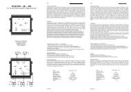
<strong>CRISTEC</strong>CPSDEC Page 6Les chargeurs CPS sont présentés en coffretmétallique dont l'indice de protection est IP22. Lacasquette débordante et le recouvrement du capotprotégent le chargeur contre les ruissellements d'eau.L'appareil est conditionné pour un fonctionnementen ambiance marine et pour des applicationsmobiles.Toute la gamme CPS délivre une tension de sortiede 12 ou 24 V régulée filtrée. En cas de coupurebatterie le chargeur alimente les utilisations sansdommage.Installation et Connexions La configuration des appareils en sortie d'usine estla suivante : Réseau 230 Vca Batterie Plomb/Antimoine Mode de charge : Boost ON (courbe de charge3 états) Réglage de la tension de sortie en Floating : à 13,8 V ± 1 % à vide pour les modèles 12 V à 27,4 V ± 1 % à vide pour les modèles 24V L’arrivée des câbles se fait au travers de presseétoupesauf pour les modèles 70 et 120W, pourlesquels les câbles batteries doivent être connectéssur les bornes.1.5 REFERENCES NORMATIVESAPPLIQUEESLes normes appliquées sont : NF EN 60950 + A1 + A2 (Octobre 93) : sécuritédes matériels de traitement de l'information ycompris les matériels de bureau électriques. NF EN 50081-1 (Juin 92) CEM : Norme génériqueémission NF EN 50082-1 (Juin 92) CEM : Norme génériqueimmunité NF EN 55022 (Décembre 1994) : Limites etméthodes de mesure des caractéristiques deperturbations radioélectriques produites par lesappareils de traitement de l'information.2 Caractéristiques et fonctionnement2.1 CARACTERISTIQUES TECHNIQUES2.1.1 Caractéristiques mécaniquesTous les modèles ont un indice de protection IP 22.Ils sont réalisés en acier, pour les parties "châssis" et"fermoir" et en aluminium pour la partie "embase".Ces pièces sont protégées par plusieurs couches depeinture époxy.Les dimensions hors tout et les masses des différentsmodèles sont précisées dans le tableau ci-dessous :ModèleLongueur(mm)Hauteur(mm)Profondeur(mm)Masse(Kg)12V 06A24V 03A215 160 85 1,612V 10A24V 05A215 160 85 1,712V 16A24V 08A270 205 120 2,412V 25A24V 12A270 205 120 2,912V 40A24V 20A290 235 116 3,612V 60A24V 30A356 285 133 4,624V 50A 356 285 133 524V 60A 356 285 133 5,12.1.2 Caractéristiques d'entréeTension d’entrée admissible (Vca) : 115 Vca ou 230Vca +/- 15% monophasé par sélection manuelle.Fréquence d’entrée admissible (Hz) : 47 à 63 Hz.Possibilité d'alimenter les chargeurs avec un groupeélectrogène (se reporter à la page 10).Fait à Quimper le : 24 Décembre 2002Pour la société <strong>CRISTEC</strong> SAS,
<strong>CRISTEC</strong>CPSDEC Page 7ModèleCourantd’entréenominaltypique à115 VcaCourantd’entréenominaltypique à230 VcaFusibled'entréeCalibre etformat12V 06A24V 03A2A 1A 3,15A T 5x2012V 10A24V 05A3A 1,5A 3,15A T 5x2012V 16A24V 08A4A 2A 10 A T 6,3x3212V 25A24V 12A6A 3,3A 10 A T 6,3x3212V 40A24V 20A8A 4,5 A 10 A T 6,3x3212V 60A24V 30A11 A 8 A 20 A T 6,3x3224V 50A 17 A 11 A 20 A T 6,3x3224V 60A 20 A 13 A 20 A T 6,3x322.1.3 Caractéristiques de sortie2.1.3.1 TensionLes tensions de sortie du tableau ci-dessous sontobtenues à 10 % de la puissance nominale sur lessorties BAT 1 et BAT 2. Pour les modèles disposantd’une sortie BAT D, le niveau de tension est réduitd’environ 0,4 V.Ces valeurs sont réglées en usine avec une précisionde ± 1 % et peuvent être ajustées par action sur lepotentiomètre POT U (utiliser l’outil adéquat pourtourner la vis du potentiomètre).Elles dépendent du type de batterie et du mode defonctionnement sélectionnés.ModèleBatteriePlomb/AntimoineMode "Floating"BatteriePlomb/AntimoineMode "Boost"BatteriePlomb/CalciumMode "Floating"BatteriePlomb/CalciumMode "Boost"Modèle12 VModèle24 V13,8 Vcc 27,4 Vcc14,5 Vcc 28,8 Vcc14,6 Vcc 29,0 Vcc15,4 Vcc 30,5 Vcc2.1.3.2 CourantLe tableau ci-dessous définit le courant de sortiemaximum à puissance de sortie nominale ainsi que letype et le calibre des fusibles de type automobileplacés en série sur les sorties du chargeur.ModèleCourantde sortiemaximumCalibredesfusibles12V 06A 6 A 7,5 A24V 03A 3 A 5 A12V 10A 10 A 15 A24V 05A 5 A 7,5 A12V 16A 16 A 20 A24V 08A 8 A 10 A12V 25A 25 A 2 x 15 A24V 12A 12 A 15 A12V 40A 40 A 2 x 20 A24V 20A 20 A 20 A12V 60A 60 A 3 x 20 A24V 30A 30 A 2 x 15 A24V 50A 50 A 2 x 25 A24V 60A 60 A 3 x 20 AType desfusibles desortie25707.5LITTLEFUSE257005LITTLEFUSE257015LITTLEFUSE25707.5LITTLEFUSE257020LITTLEFUSE257010LITTLEFUSE257015LITTLEFUSE257015LITTLEFUSE257020LITTLEFUSE257020LITTLEFUSE257020LITTLEFUSE257015LITTLEFUSE257025LITTLEFUSE257020LITTLEFUSE2.1.4 Tenue à l’environnementTous les chargeurs de la gamme répondent auxcaractéristiques suivantes : Température de stockage : - 20 °C à + 70 °C. Température de fonctionnement : - 10 °C à + 50 °C. Humidité : < 90 % sans condensation
<strong>CRISTEC</strong>CPSDEC Page 82.1.5 Protections et sécurité de fonctionnement2.1.5.1 Protection en entréeLes modèles CPS 70, CPS 120, CPS 190 et CPS 300sont munis d’une protection bipolaire réalisée par 2fusibles F1 et F2 dont les calibres sont donnés auparagraphe 2.1.2.Tous les autres modèles sont munis d’une protectionunipolaire par un fusible F1 dont le calibre est donnéau paragraphe 2.1.2.2.1.5.2 Protection en sortieLa protection en sortie est réalisée à l’aide d’unfusible placé en série sur la borne "–" de l’appareilafin de limiter le nombre de fusibles. Le calibre et letype de ce fusible sont définis dans le tableau duparagraphe 2.1.3.2.2.1.5.3 Sécurités supplémentairesTous les modèles sont munis des sécurités suivantes : Protection contre les surtensions d’entrée parvaristance (275 Vca) : élément soudé sur la carteélectronique. Remplacement par une personnehabilitée uniquement. Protection contre les échauffements anormaux dessemiconducteurs de puissance. Protection contre les inversions de polarités.(rupture des fusibles de sortie) Protection contre les surcharges de sortie parlimitation de la puissance à la valeur nominale dechaque modèle.Pour les modèles 24V 50A et 24V 60A possibilité deréduire la puissance par un bouton potentiométriqueextérieur fixé au coffret.2.1.5.4 Fonctionnement du ventilateurLes modèles CPS 70-1A, CPS 70-2A, CPS 120-1A,CPS 120-2A, CPS 190-1A, CPS 190-2A et CPS 300-2A ne sont pas équipés de ventilateurélectromécanique : ventilation naturelle.Les autres modèles sont équipés de ventilateurélectromécaniques. Ils sont pilotés par des sondesthermiques. Ils ne sont activés que si des pointssensibles atteignent une certaine température.2.1.6 OptionsLes options ne font pas partie de la fourniture de basedes chargeurs de batteries. Elles sont disponiblesauprès de votre revendeur. Seuls les optionscommercialisées par <strong>CRISTEC</strong> peuvent être montéesavec les chargeurs. Voltmètre analogique 48x48mm pour visualiserla tension de charge en amont des diodes derépartition.RéférenceModèleVoltmètreModèle 12 V VLT 0012Modèle 24 V VLT 0024 Ampèremètre analogique 48x48mm pourvisualiser le courant de charge total des batteries(SHUNT intégré au chargeur)ModèleRéférenceAmpèremètre12V 06A AMP 0070/124V 03A AMP 0070/212V 10A AMP 0120/124V 05A AMP 0120/212V 16A AMP 0190/124V 08A AMP 0190/212V 25A AMP 0300/124V 12A AMP 0300/212V 40A AMP 0480/124V 20A AMP 0480/212V 60A AMP 0720/124V 30A AMP 0720/224V 50A AMP 1200/224V 60A AMP 1440/2 Compensation de température de batterie*Longueur dela sondeRéférence dela sonde1 m STEMP/13 m STEMP/3* : En option pour tous les modèles à l’exception desmodèles CPS 70 et CPS 120.La sonde de température doit être connectée auchargeur après avoir débranché préalablement lesbatteries du chargeur. Un bornier plastique prévu àcet effet est présent sur la carte chargeur.La sonde de température doit être protégée contre lescoupures, elle ne doit pas être écrasée. Le respect dela connexion est impératif pour le bonfonctionnement du chargeur. Les sondes référencéesci-dessus sont conçues pour n'être utilisées que surles chargeurs CPS.Le branchement est différent selon les modèles :
<strong>CRISTEC</strong>CPSDEC Page 9 Modèles CPS 190 et CPS 300 :Sur ces chargeurs, 3 bornes sont prévues pourrecevoir la sonde température.Voir le plan joint : Les bornes sont repérées par letexte "sonde de température"(2 bornes + et 1 borne -).Connecter le câble Blanc sur une des deux bornesplus.Connecter le câble Jaune sur l'autre borne plus.Connecter le câble Marron sur la borne moins dumilieu. Modèles CPS 480, 720, 1200 et 1440 :Sur ces chargeurs, 2 bornes sont prévues pourrecevoir la sonde température.Voir le plan joint : Les bornes sont repérées par letexte "sonde de température" (1 borne + et 1 borne -).Couper et isoler le câble Jaune.Connecter le câble Blanc sur la borne plus.Connecter le câble Marron sur la borne moins.2.2 FONCTIONNEMENT DE L'APPAREIL2.2.1 Tension de sortieL'appareil délivre une tension adaptée à la rechargede 1, 2 ou 3 batteries séparées.Tous les modèles (à l'exception des CPS 70 et CPS120) sont dotés d'une sortie adaptée à la recharge dela batterie moteur (sortie BAT D). Cependant, pourles chargeurs CPS 70 et CPS 120, l'utilisateur peutconnecter une des deux sorties sur la batterie moteur.2.2.2 Synoptique2.2.3 Principe de fonctionnementLes chargeurs de batteries de la gamme CPS sontconçus sur la base de convertisseur à découpagehaute fréquence qui transforme le signal alternatif entension continue, régulée, filtrée et adaptée à lacharge des batteries d'accumulateurs.2.2.4 Fonctionnement détailléLe fonctionnement du chargeur de batteries estentièrement automatique, après sélection préalable duréseau d'entrée, du type de batterie et du type decharge.2.2.4.1 Fonctionnement des sélecteurs Sélecteur de tension réseauL’appareil est équipé d’un sélecteur de tensioninterne autorisant son fonctionnement sur 2 typesde réseaux : Réseau Européen :230 Vca 50/60Hz Autres réseaux (USA, etc …) : 115 Vca 50/60Hz Sélecteur du type de batterieL’appareil est équipé d’un sélecteur interneautorisant son fonctionnement sur 2 types debatteries par simple action sur un interrupteur : Batterie au Plomb/Antimoine : "ANT" Batterie au Plomb/Calcium : "CAL"
<strong>CRISTEC</strong>CPSDEC Page 10 Sélecteur du type de chargeL’appareil est équipé d’un sélecteur interneautorisant 2 types de charge par action sur uninterrupteur : Charge en mode Floating : "BOOST OFF" Charge en mode Boost pendant 6 heures ±30 mn puis passage automatique en modeFloating : "BOOST ON".NB : La tension de mode Boost à vide estsupérieure d’environ 5 % à la tension de modeFloating à vide. Bouton potentiométrique de limitation depuissancePour les modèles 24V 50A et 24V 60A, un boutonpotentiométrique positionné à l'extérieur ducoffret (côté droit) permet de limiter la puissancedu chargeur. Ceci permet d’éviter la disjonctionéventuelle du différentiel placé en début de ligne230V.2.2.4.2 Fonctionnement des indicateursCes indicateurs sont disposés en face avant del'appareil et permettent une visualisation du modede fonctionnement de l'appareil. Indicateur de "Présence réseau"Cet indicateur est éteint dans les cas suivants : Absence ou dégradation du réseau alternatif, Rupture du fusible d'entrée, Dysfonctionnement interne du chargeur debatteries. Indicateur de mode de charge Boost ou FloatingCet indicateur est éteint dans les cas suivants : Rupture du fusible de sortie, Absence de tension en sortie du chargeur (ex :réseau alternatif non connecté).Cet indicateur est allumé en permanencelorsque le mode de charge Floating : "BOOSTOFF" est sélectionné et que le fonctionnementdu chargeur est correct.Cet indicateur est clignotant si le mode defonctionnement Boost : "BOOST ON" a étésélectionné. Ce mode de fonctionnement dure 6heures ± 30 minutes avant que l'appareil nerepasse automatiquement en mode Floating. Ace moment, l'indicateur reste allumé fixe.2.2.4.3 Fonctionnement particulier Batteries spécialesLes réglages réalisés en usine sont effectués dansle cadre standard d'utilisation de batteriesPlomb/Antimoine et Plomb/Calcium.Se référer à un installateur professionnel quieffectuera les réglages particuliers en accord avec lesspécifications du constructeur d'accumulateurs et entenant compte des particularités de l'installation. Groupes électrogènesLe chargeur de batteries <strong>CRISTEC</strong> est conçu pourfonctionner sur groupe électrogène.Dans certains cas, les groupes électrogènes peuventgénérer des surtensions importantes. Avantraccordement du chargeur, vérifier la compatibilitédes caractéristiques du groupe et celles du chargeur :puissance, tension, surtension, fréquence, courant …3 Dispositions relatives à l'installation3.1 GENERALITESCe paragraphe traite des dispositions relatives àl'installation de l'équipement.L'installation et la première mise en fonctionnementdoivent être assurées par un électricien ou uninstallateur professionnel selon les normes en vigueur(dans le cas des navires de plaisance, se conformer àla norme internationale ISO 13297).L'installateur devra prendre connaissance de cemanuel d'utilisation et devra informer les utilisateursdes dispositions relatives à l'utilisation et à la sécuritécontenues au paragraphe 5.3.2 FOURNITURE LIVREELa fourniture <strong>CRISTEC</strong> comprend les élémentssuivants : 1 boîtier métallique contenant la fonctionélectronique chargeur de batteries, La présente documentation (manueld'utilisation).3.3 FOURNITURES COMPLEMENTAIRESNECESSAIRES A L'INSTALLATIONELECTRIQUECes éléments ne font pas partie de la fourniture<strong>CRISTEC</strong>.Les références des fournitures complémentairesnécessaires au bon fonctionnement de l'appareil sontdéfinies dans les paragraphes ci-dessous : tout nonrespectde ces dispositions entraîne une annulation dela garantie constructeur.
<strong>CRISTEC</strong>CPSDEC Page 113.3.1 Câble de liaison réseau public ou groupeélectrogèneSelon les longueurs de ligne, les câbles de liaisonréseau alternatif doivent être obligatoirement desection supérieure ou égale aux valeurs indiquéesdans le tableau ci-dessous :Modèle12V 06A24V 03A12V 10A24V 05A12V 16A24V 08A12V 25A24V 12A12V 40A24V 20A12V 60A24V 30A24V 50A24V 60ASection minimaleet types de câbleen 115 VcaFourni3 x 1,5 mm²HO7-VK3 x 2,5 mm²HO7-VK3 x 2,5 mm²HO7-VK3 x 4 mm²HO7-VK3 x 4 mm²HO7-VKSection minimaleet types de câbleen 230 VcaFourni3 x 1,5 mm²HO7-VK3 x 1,5 mm²HO7-VK3 x 1,5 mm²HO7-VK3 x 2,5 mm²HO7-VK3 x 2,5 mm²HO7-VKUtiliser impérativement des embouts à colleretteisolante en corrélation avec les normes del'installation pour le raccordement de l'entrée réseau.Le conducteur PE (communément appelé "terre", filvert/jaune) de la source alternative doitimpérativement être raccordé au chargeur sur laborne prévue à cet effet.3.3.2 Câble de liaison batterieJusqu'à 3 mètres, les câbles de liaison batteriesdoivent être obligatoirement de section supérieure ouégale aux valeurs indiquées dans le tableau cidessous:ModèleSection des câblesde liaison batterieet type de câbleType des cossesSection du câbleet diamètre dutrou de la cosse12V 06A 2,5 mm² HO7-VK Utiliserimpérativement24V 03A 1,5 mm² HO7-VK des embouts à12V 10A 4 mm² HO7-VKcollerette isolante(selon la norme24V 05A 2,5 mm² HO7-VK NF G63-023)12V 16A 6 mm² HO7-VK 6 mm² - 5 mm24V 08A 4 mm² HO7-VK 4 mm² - 5 mm12V 25A 10 mm² HO7-VK 10 mm² - 5 mm24V 12A 6 mm² HO7-VK 4 mm² - 5 mm12V 40A 16 mm² HO7-VK 16 mm² - 5 mm24V 20A 10 mm² HO7-VK 10 mm² - 5 mm12V 60A 16 mm² HO7-VK 16 mm² - 6 mm24V 30A 10 mm² HO7-VK 10 mm² - 6 mm24V 50A 16 mm² HO7-VK 16 mm² - 6 mm24V 60A 16 mm² HO7-VK 16 mm² - 6 mmConserver impérativement les presse-étoupe sur laface inférieure du coffret pour éviter toutedégradation des câbles de liaison sur les paroismétalliques du coffret et garantir une double isolationentre les conducteurs actifs et la masse électrique.3.3.3 Câble de liaison voltmètre et ampèremètres(sur certains modèles uniquement)Ces câbles doivent être de section supérieure ouégale à 0,34 mm² et de type : KZ0506 - 600 V.Ils doivent être munis d'embouts à collerette isolanteselon la norme NF G 63-023.Conserver impérativement les presse-étoupe sur laface inférieure du coffret pour éviter toutedégradation des câbles de liaison sur les paroismétalliques du coffret et garantir une double isolationentre circuit de charge et masse électrique.3.3.4 Câble de liaison à la masse de l'installationLe câble de liaison à la masse de l’installation doitimpérativement être connecté à la vis de masse situéeà l’intérieur du chargeur.Le câble utilisé doit avoir une section minimale de2,5 mm², être de type HO7-VK et muni d’une cosseappropriée.
<strong>CRISTEC</strong>CPSDEC Page 123.4 RECOMMANDATIONS PARTICULIERESRELATIVES A L'INSTALLATION3.4.1 Positionnement du coffret3.4.1.1 Dispositions vis à vis des échauffements del'appareilL'équipement est conçu pour être monté sur uneparoi verticale selon les indications fournies sur lesplans en annexe.Il est impératif de conserver une zone de 150 mm surles faces latérales du coffret.Le refroidissement est garanti par ventilation forcéesur certains modèles. L'installateur prendra lesdispositions nécessaires pour que la température d'airà l'entrée (voir plan en annexe) soit inférieure à 40° Cdans les conditions extrêmes de fonctionnement.Les dispositions seront également prises pourpermettre un dégagement de l'air chaud de chaquecôté du chargeur.3.4.1.2 Dispositions vis à vis des chutes d'eau etruissellementL'indice de protection est IP22 et l'emplacement duchargeur doit être choisi pour éviter toute pénétrationd'humidité ou de sel dans le chargeur.Ces incidents peuvent générer une dégradationirréversible du matériel et un danger potentiel pourl'utilisateur.Il est recommandé de positionner l'appareil dans unendroit sec, bien ventilé et éloigné de toute source dechaleur.3.4.1.3 Dispositions vis à vis des batteriesLes batteries raccordées au chargeur sontsusceptibles d'émettre des gaz explosifs pendant laphase de recharge.Il est donc recommandé : De proscrire les équipements générant desétincelles et des flammes à proximité desbatteries. De positionner les batteries dans un endroit aéré etventilé. Pour l’installation des batteries, prendre encompte les prescriptions du constructeurd'accumulateurs.3.4.1.4 Dispositions vis à vis des courants de fuiteaccidentels à la terre Courant de fuite accidentel entre phase et terreSe conformer à la norme NFC 15-100 pour lesprécautions d'installation.Faire réaliser les travaux de raccordement par unélectricien ou un installateur professionnel.Le chargeur doit être connecté sur une installationdisposant d'un disjoncteur bipolaire différentiel desensibilité de 30 mA. Courant de fuite accidentel entre circuit de chargeet masseLa détection des courants de fuite accidentels à lamasse doit être assurée par un dispositif deprotection extérieur au chargeur (dispositif àcourant différentiel résiduel ou contrôleurd'isolement).Le calibre et la nature de la protection serontadaptés par l'installateur en fonction des risques.Des précautions particulières sont recommandéessur toute installation susceptible de craindre desphénomènes électrolytiques.La réglementation impose la présence de coupebatterie en sortie sur le pôle + et le pôle -.3.4.1.5 Dispositions vis à vis des chocs de foudreDans les zones géographiques fortement exposées, ilpeut être utile de placer un parafoudre en amont duchargeur afin d'éviter toute dégradation irréversiblede ce dernier.3.4.1.6 Dispositions vis à vis des perturbationsélectromagnétiques générées par l'appareil Utiliser du câble blindé pour toutes les connexions(*). Le blindage doit être raccordé côté émetteur etcôté récepteur à la masse. Réduire au maximum la longueur des câbles et lesconnexions des blindages. Faire passer les câbles au plus près des masses (lescâbles "volants" ou les boucles sont à éviter -plaquer les câbles contre les masses). Séparer les câbles d'alimentation et d'utilisation. Séparer les câbles de puissance et les câbles decontrôle (minimum 200 mm). Les câbles doivent assurer uniquementl'alimentation de l'appareil. Une dérivation ou unpontage afin d'alimenter un autre appareil sont àprohiber.(*) Ceci est un conseil d'installation et non uneobligation. L'électricien installateur décide,compte tenu de l'environnement CEM, de l'emploide câble blindé ou non.
<strong>CRISTEC</strong>CPSDEC Page 133.5 DISPOSITIONS RELATIVES A LA MISEEN SERVICECe paragraphe énumère les opérations à effectuerpour la mise en service de l'équipement. Il convientde respecter strictement ces instructions avant lapremière mise sous tension.3.5.1 Sélection de la tension réseau 115 / 230 VCALa sélection du réseau d'entrée se fait à l'aide dusélecteur de repère FN1 / FN2 à l'intérieur du coffretmétallique.Les précautions d'utilisation de ce sélecteur sont lessuivantes : Le calibre des disjoncteurs placés en amont doitcorrespondre au besoin de l'équipement. La manipulation du sélecteur se fait en l'absencede tension d'entrée alternative. Positionner le sélecteur de tension en fonction dutype de réseau alternatif utilisé.Toute manipulation incorrecte de ce sélecteur peutendommager l'appareil de manière irréversible. Si le chargeur alimente 1, 2 ou 3 parcs batteries àfaible taux de décharge, il est recommandé desélectionner le mode "BOOST OFF". En cas d'instabilité sur le réseau alternatifd'alimentation du chargeur (micro-coupures > 500ms), le chargeur va réinitialiser le Boost de 6heures ± 30 minutes et entraîner, à termes, ladétérioration des batteries. Dans ce cas de figurenous recommandons de sélectionner le mode"BOOST OFF".3.5.4 Vérification de la tension de chargeAvant raccordement des batteries au chargeur, il estimpératif de vérifier la polarité des accumulateurs.Vérifier également la tension des batteries à l'aided'un voltmètre étalonné. Une valeur trop basse detension sur certains types d'accumulateurs peutindiquer une dégradation irréversible et uneimpossibilité de recharge.3.5.5 Raccordement des optionsContacter impérativement votre revendeur ou leservice commercial <strong>CRISTEC</strong>.3.5.2 Sélection du type de batterieLes plans en annexe indiquent le positionnement dusélecteur en fonction du type de batteries utilisé.Les précautions d'utilisation de ce sélecteur sont lessuivantes : Vérifier impérativement la compatibilité de lasélection et le type de batterie raccordé avant toutemise sous tension.3.5.3 Sélection de mode de chargeLes plans en annexe indiquent le positionnement dusélecteur en fonction du type de charge souhaité.Les précautions d'utilisation de ce sélecteur sont lessuivantes : Vérifier impérativement la compatibilité de latension de mode "BOOST ON" sélectionnéeavec le type de batterie raccordé. En période d'hivernage, ou de raccordementprolongé du chargeur de batteries, si le chargeurreste alimenté, positionner systématiquement lecommutateur sur "BOOST OFF". En cas d'utilisation de la fonction "BOOST ON",raccorder impérativement la batterie de démarragemoteur à la sortie BAT D sur les modèlesdisposant de 3 sorties.
<strong>CRISTEC</strong>CPSDEC Page 144 Dispositions relatives à la maintenance età la réparation de l'équipement4.1 GENERALITESCe paragraphe traite des dispositions relatives à lamaintenance et aux réparations de l'équipement. Lebon fonctionnement et la durée de vie du produit sontconditionnés par le strict respect desrecommandations contenues ci-après.4.2 MAINTENANCE DES EQUIPEMENTS Déconnecter le chargeur de batteries du réseaualternatif pour toutes les opérations demaintenance. Si les appareils sont placés dans une ambiancepoussiéreuse, les nettoyer périodiquement paraspiration, les dépôts de poussière pouvant altérerl'évacuation de la chaleur. Vérifier l'état de charge des batteries tous les 3mois. Une vérification annuelle du serrage des écrous etvis est nécessaire pour garantir le bonfonctionnement de l'appareil (particulièrement enmilieu perturbé : vibrations, chocs, écarts detempérature importants, etc ...). Une visite technique complète par un intervenantrecommandé <strong>CRISTEC</strong> est conseillée tous les 5ans. Ce contrôle technique général peut égalementêtre réalisé en nos usines.5 Dispositions relatives à la sécurité5.1 REFERENCES NORMATIVES Matériel de classe I selon la norme NF EN 60950. Les prescriptions d'installation sont contenues dansla norme NFC 15-100 et la norme spécifique "auxnavires de plaisance – systèmes électriques –Installation de distribution de courant alternatif"de référence ISO 13297.5.2 PRECAUTIONS RELATIVES A LASECURITE DES PERSONNES L'installation doit être réalisée par un électricienou un installateur professionnel. Le réseau d'entrée alternatif doit être coupé avanttoute intervention sur l'équipement.5.3 PRECAUTIONS RELATIVES A LAPROTECTION CONTRE LE FEU ETLES EXPLOSIONS Utiliser les fusibles définis au paragraphe 3.1. A proximité des batteries : Ventiler le local, Ne pas fumer, Ne pas utiliser de flamme vive.4.3 REPARATION DES EQUIPEMENTS Déconnecter le chargeur de batteries du réseaualternatif et des batteries pour toute opération deréparation. En cas de rupture des fusibles, respecter le calibreet le type de fusibles préconisés au paragraphe2.1. Pour toute autre intervention de réparation, contacterun revendeur ou la Société <strong>CRISTEC</strong>.
<strong>CRISTEC</strong>CPSDEC Page 15DESCRIPTIONCONTENTSPage1. INTRODUCTION 161.1 INSTALLATION AND OPERATING MANUAL 161.2 VALIDITY OF THIS DOCUMENT 161.3 GUARANTEE 161.4 BRIEF PRESENTATION 161.5 REFERENCE STANDARDS APPLIED 172. CHARACTERISTICS AND OPERATION 172.1 TECHNICAL CHARACTERISTICS 172.1.1 Mechanical characteristics 172.1.2 Input characteristics 172.1.3 Output characteristics 182.1.4 Environmental specification 182.1.5 Protection and operating safety 192.1.6 Options 192.2 CHARGER OPERATION 202.2.1 Output voltage 202.2.2 Block diagram 202.2.3 Principle of operation 202.2.4 Detailed operation 203. INSTALLATION 213.1 INTRODUCTION 213.2 ITEMS SUPPLIED 213.3 ADDITIONAL SUPPLIES NECESSARY FOR ELECTRICAL INSTALLATION 213.3.1 Cable connecting to the public mains supply or to an electricity generating set 223.3.2 Battery connection cable 223.3.3 Voltmeter and Ammeter link cable (only on certain models) 223.3.4 Installation of the earth cable 223.4 SPECIAL RECOMMENDATIONS FOR INSTALLATION 233.4.1 Case position 233.5 COMMISSIONING 243.5.1 Selecting the mains supply voltage 243.5.2 Selecting battery type 243.5.3 Selecting charge mode 243.5.4 Verifying the charge voltage 243.5.5 Connecting up the options 244. MAINTENANCE AND REPAIR OF EQUIPMENT 254.1 INTRODUCTION 254.2 EQUIPMENT MAINTENANCE 254.3 EQUIPMENT REPAIR 255. SAFETY 255.1 STANDARDS REFERENCES 255.2 PRECAUTIONS RELATING TO PERSONNEL SAFETY 255.3 PRECAUTIONS RELATING TO PROTECTION AGAINST FIRE AND EXPLOSION 25
<strong>CRISTEC</strong>CPSDEC Page 161 Introduction1.1 INSTALLATION AND OPERATINGMANUALThe present document applies to chargers in the<strong>CRISTEC</strong> CPS range of battery chargers listedbelow.U/I RatingPower <strong>CRISTEC</strong>(Watts) Reference12V 06A CPS 70-1A7024V 03ACPS 70-2A12V 10A CPS 120-1A12024V 05ACPS 120-2A12V 16A CPS 190-1A19024V 08ACPS 190-2A12V 25A CPS 300-1A30024V 12ACPS 300-2A12V 40A CPS 480-1A48024V 20ACPS 480-2A12V 60A CPS 720-1A72024V 30ACPS 720-2A24V 50A 1200 CPS 1200-2A24V 60A 1440 CPS 1440-2AThis manual is intended for users, installers andequipment maintenance personnel who must ensurethey understand the present document before anyintervention on the charger.1.2 VALIDITY OF THIS DOCUMENTThis document is the property of <strong>CRISTEC</strong> ; all theinformation contained in this document applies to theaccompanying product. The company reserves theright to modify the specifications without priornotice.1.3 GUARANTEEFailure to comply with the rules for installation andoperation cancels the manufacturer's guarantee andabsolves <strong>CRISTEC</strong> of all responsibility.The period of guarantee is 36 months. It applies toparts and labour for any equipment returned to thefactory.Only parts acknowledged to have been defectivefrom the outset will be replaced under the guaranteeEquipment which has been misused or damaged byerrors in connections, impacts, falls or which isdefective from having been worked upon by personsother than those authorised by <strong>CRISTEC</strong> Industries.Equipment which has been installed or operated atvariance with procedures outlined in the manualprovided with each unit.Under no circumstances, can any indemnity begranted by this warranty.This warranty does not apply to the followingterms : Transportation and packaging charges to and fromthe factory or authorised service station. Damage sustained in shipment, apparent orconcealed.Claims for such damage must be reported and filedwith the carrier by the person receiving theequipment.1.4 BRIEF PRESENTATIONChargers in the CPS (charge, programmable,selective) range provide specific charging for 1, 2 or3 banks of batteries in accordance with the batterymanufacturers' specifications.An internal switch selects the type of battery :Lead/Antimony (ANT) or Lead/Calcium (CAL).Entirely automatic with built-in charge distribution,they can remain permanently connected to thebatteries in complete safety and do not need to bedisconnected when starting the engine.The timed Boost function, which allows the batteriesto be charged more quickly (6 hours ± 30 minutes),may be activated or inhibited by means of an internalswitch as the user wishes: "BOOST ON" position to enable Boost "BOOST OFF" position to disable BoostIn general, starter batteries are always better chargedthan auxiliary and utility batteries. In order toincrease its life by not overcharging, it is allocated itsown specific output .CPS chargers are protected against polarity reversaland transient short-circuits.Accepting a wide range of input frequencies andvoltages, they work from electricity generating setsand may be connected to international marinas withinthe specified tolerance range (115/230Vac ± 15%,selected by internal jumper).Two indicator lamps on the front panel show thestate of the charger : Green LED Connection to ac mains Yellow LED Flashing : charging "BOOSTON"Steady : charging "BOOST OFF"
<strong>CRISTEC</strong>CPSDEC Page 17CPS chargers are supplied in a metal case with IP22protection rating. The overhanging cover and hoodprotect the charger from running water.The equipment is designed to work in a marine andmobile environment.All of the CPS range output a filtered and regulatedvoltage of 12 or 24 V. In the event of batterydisconnection, the charger supplies the loads withoutdamage.Installation and Connections When they leave the factory the chargers areconfigured as follows : Mains supply : 230Vac Battery : Lead/Antimony Charging mode : Boost ON, 3 step charging curve Output voltage setting in Floating : at 13.8 V ± 1% off load for 12 V models at 27.4 V ± 1% off load for 24 V models Cable entry is via cable glands except for 70 and120 W models for which the battery cables mustbe attached to terminals.1.5 REFERENCE STANDARDS APPLIEDThe standards applied are : NF EN 60950 + A1 + A2 (October 93) : safety ofinformation processing equipment includingelectrical office equipment. NF EN 50081-1 (June 92) EMC : Generic standardfor emissions NF EN 50082-1 (June 92) EMC : Generic standardfor immunity NF EN 55022 (December 1994) : Limits andmethods for measuring the characteristics of RFinterference produced by information processingequipment.2 Characteristics and operation2.1 TECHNICAL CHARACTERISTICS2.1.1 Mechanical characteristicsAll models have an IP 22 protection rating. Thecover and clasp are made of steel and the base ismade of aluminium. These parts are protected byseveral coats of epoxy paint.Overall dimensions and weights of the variousmodels are specified in the table below :ModelLength(mm)Height(mm)Depth(mm)Weight(kg)12V 06A24V 03A215 160 85 1,612V 10A24V 05A215 160 85 1,712V 16A24V 08A270 205 120 2,412V 25A24V 12A270 205 120 2,912V 40A24V 20A290 235 116 3,612V 60A24V 30A356 285 133 4,624V 50A 356 285 133 524V 60A 356 285 133 5,12.1.2 Input characteristicsPermissible input voltage (Vac) : 115Vac or 230Vac+/- 15% single phase by manual selection.Permissible input frequency (Hz) : 47 to 63 Hz.Possibility to power the chargers from a generatingset (please refer to page 21).Enacted at Quimper on : 24 December 2002For and on behalf of <strong>CRISTEC</strong> SAS,
<strong>CRISTEC</strong>CPSDEC Page 18ModelTypicalinputcurrentrating at115VacTypicalinputcurrentrating at230VacInternalinput fuserating andformat12V 06A24V 03A2A 1A 3,15A T 5x2012V 10A24V 05A3A 1,5A 3,15A T 5x2012V 16A24V 08A4A 2A 10 A T 6,3x3212V 25A24V 12A6A 3,3A 10 A T 6,3x3212V 40A24V 20A8A 4,5 A 10 A T 6,3x3212V 60A24V 30A11 A 8 A 20 A T 6,3x3224V 50A 17 A 11 A 20 A T 6,3x3224V 60A 20 A 13 A 20 A T 6,3x322.1.3 Output characteristics2.1.3.1 VoltageThe output voltages shown in the table below areobtained at 10% of rated power on outputs BAT 1and BAT 2. For those models having a BAT Doutput, the voltage level is reduced by about 0.4 V.These values are set in the factory with an accuracyof ± 1% and can be adjusted by turning thepotentiometer POT U (use a suitable tool for turningthe potentiometer screw).They depend on the type of battery and mode ofoperation selected.ModelLead/AntimonyBattery"Floating" Mode "Lead/AntimonyBattery"Boost" ModeLead/CalciumBattery "Floating"ModeLead/CalciumBattery"Boost" ModeModel12 VModel24 V13,8 V 27,4 V14,5 V 28,8 V14,6 V 29,0 V15,4 V 30,5 V2.1.3.2 CurrentThe table below defines the maximum output currentat rated output power as well as the type and rating ofthe carsocket type fuses placed in series with thecharger outputs.ModelMaximumoutputcurrentFuseratingOutputtype of fuse12V 06A 6 A 7,5 A25707.5LITTLEFUSE24V 03A 3 A 5 A257005LITTLEFUSE12V 10A 10 A 15 A257015LITTLEFUSE24V 05A 5 A 7,5 A25707.5LITTLEFUSE12V 16A 16 A 20 A257020LITTLEFUSE24V 08A 8 A 10 A257010LITTLEFUSE12V 25A 25 A2570152 x 15 ALITTLEFUSE24V 12A 12 A 15 A257015LITTLEFUSE12V 40A 40 A2570202 x 20 ALITTLEFUSE24V 20A 20 A 20 A257020LITTLEFUSE12V 60A 60 A2570203 x 20 ALITTLEFUSE24V 30A 30 A2570152 x 15 ALITTLEFUSE24V 50A 50 A2570252 x 25 ALITTLEFUSE24V 60A 60 A2570203 x 20 ALITTLEFUSE2.1.4 Environmental specificationAll chargers in the range meet the followingcharacteristics : Storage temperature : - 20°C to + 70°C. Operating temperature : - 10°C to + 50°C. Humidity : < 90% non-condensing
<strong>CRISTEC</strong>CPSDEC Page 192.1.5 Protection and operating safety2.1.5.1 Input protectionModels CPS 70, CPS 120, CPS 190 and CPS 300 arefitted with two pole protection by 2 fuses F1 and F2whose ratings are given in section 2.1.2.All other models are fitted with single pole protectionby a fuse F1 whose rating is given in section 2.1.2.2.1.5.2 Output protectionOutput protection is provided by a fuse placed inseries with the "–" terminal of the charger in order toreduce the number of fuses. The rating and type ofthis fuse are defined in the table in section 2.1.3.2.2.1.5.3 Additional safety devicesAll models are fitted with the following safetydevices : Protection against input voltage surges by aVaristor (275 Vac). Protection against abnormal heating of the powersemiconductors. Protection against polarity reversal (output fuseblows) Protection against overloads on the output bylimiting the power to the rated value for eachmodel.It is possible to reduce the power on the 24V 50Aand 24V 60A models by means of an externalpotentiometric switch fixed on the cabinet.2.1.5.4 Fan FunctioningThe following charger models do not have anyelectromechanical fan; they have a natural ventilation :CPS 70-1A, CPS 70-2A, CPS 120-1A, CPS 120-2A,CPS 190-1A, CPS 190-2A and CPS 300-2A.All other CPS charger models are equipped with anelectromechanical fan. They are driven through atemperature sensor and they are only activated ifsome specific sensitive devices reach a certain levelof temperature.2.1.6 OptionsThe options do not form part of the basic batterycharger supply. They are available from yourreseller. The only extra options that could work withthe CPS chargers are the pieces of equipmentproposed as an option by <strong>CRISTEC</strong>. Analogue voltmeter for displaying the chargingvoltage at the input side of the chargedistribution diodes.ModelVoltmeterreferenceModel 12 V VLT 0012Model 24 V VLT 0024 48x48mm analogue ammeter for displaying thetotal battery charging (SHUNT already fittedinto the charger PCB)ModelAmmeterreference12V 06A AMP 0070/124V 03A AMP 0070/212V 10A AMP 0120/124V 05A AMP 0120/212V 16A AMP 0190/124V 08A AMP 0190/212V 25A AMP 0300/124V 12A AMP 0300/212V 40A AMP 0480/124V 20A AMP 0480/212V 60A AMP 0720/124V 30A AMP 0720/224V 50A AMP 1200/224V 60A AMP 1440/2 Battery temperature compensation *Probe lengthProbereference1 m STEMP/13 m STEMP/3* : Available as an option on all CPS charger modelsexcept CPS 70 et CPS 120.The temperature sensor has to be connected to thecharger after having disconnected the batteries to thecharger first. A special plastic terminal is availableon the bottom of the charger board. The temperaturesensor has to be protected against any cuts and shallnot be scratched. Our connection recommendationshave to be respected in order to insure the rightoperating of the charger. The here-above mentionedsensors can only be used on CPS chargers.
<strong>CRISTEC</strong>CPSDEC Page 20The connecting is different depending on models : CPS 190 and CPS 300 models :There are 3 terminals on these models to connectthe temperature sensor. Please refer to theattached drawing. The proper sensor terminals areshown on the drawing as “temperature sensor” (2off positive terminals and one off negativeterminal).The white cable has to be connected to one of thetwo positive terminals. The yellow cable will beconnected to the remaining positive terminal.The negative terminal will be linked to the browncable. CPS 480, 720, 1200 and 1440 models :There are 2 terminals on these models to connectthe temperature sensor.Please refer to the attached drawing : the propersensor terminals are shown on the drawing as“temperature sensor” (1 off positive terminals andone off negative terminal).Cut out and isolate the yellow cable. The white cablehas to be connected to the positive terminal. Thenegative terminal will be linked to the brown cable.2.2 CHARGER OPERATION2.2.1 Output voltageThe charger delivers a voltage suitable for recharging1, 2 or 3 separate batteries.All models (except for CPS 70 and CPS 120) arefitted with an output suitable for recharging theengine battery (BAT D output). Nevertheless, forchargers CPS 70 and CPS 120, you can use one ofthe outputs for recharging engine battery.2.2.2 Block diagram2.2.3 Principle of operationThe CPS range of battery chargers are designed onthe basis of a high frequency switching converterwhich transforms the ac signal into a regulated,filtered dc voltage suitable for charging accumulatorbatteries.2.2.4 Detailed operationAfter the initial selection of input mains, type ofbattery and type of charge, battery charger operationis entirely automatic.2.2.4.1 Selector operation Mains voltage selectorThe charger is fitted with an internal voltageselector enabling it to operate on 2 types of Mainssupply : European mains supply : 230Vac – 50/60Hz Other mains supplies (USA, etc. …) :115Vac 50/60Hz Battery type selectorThe charger is fitted with an internal selectorenabling it to operate on 2 types of battery just bychanging a switch: Lead/Antimony battery : "ANT" Lead/Calcium battery : "CAL"
<strong>CRISTEC</strong>CPSDEC Page 21 Charge type selectorThe charger is fitted with an internal selectorenabling it to provide 2 types of charging just bychanging a switch : Charge in Floating mode : "BOOST OFF" Charge in Boost mode for 6 hours ± 30 minutesthen automatic switch to Floating mode :"BOOST ON"NB : The Boost voltage off load is about 5%higher than the off load Floating mode voltage. Potentiometric switch of power limitationFor 1200W and 1440W models, a potentiometricswitch located on the right hand side outside thecabinet enables to limit the charger power. Thissystem allows to avoid the possible disjunction ofthe AC breakers.2.2.4.2 Operation of the indicatorsThese indicators are fitted on the charger front paneland display the unit's mode of functioning. "Mains present" indicatorThis indicator is extinguished in the followingcircumstances : Absence or degradation of the ac mains supply, Input fuse blown, Internal malfunction of the battery charger. Boost or Floating charge mode indicatorThis indicator is extinguished in the followingcircumstances : Output fuse blown, Absence of voltage at charger output (forexample, ac mains not connected).This indicator lights steadily when the Floatingcharge mode : "BOOST OFF" has beenselected and the charger is functioningcorrectly.This indicator flashes if Boost mode operation :"BOOST ON" has been selected. This mode ofoperation lasts for 6 hours ± 30 minutes beforethe charger automatically switches to Floatingmode operation. At that moment, the indicatorchanges to a fixed steady light.Refer to a professional installer for special settings tomatch the battery manufacturer's specifications,taking into account the special features of theinstallation. Electricity generating setsThe <strong>CRISTEC</strong> battery charger is designed for usefrom an electricity generating set.In certain circumstances, generating sets can generatelarge over-voltage. Before connecting the charger,check that the charger is compatible with thegenerator: power, voltage, voltage surges, frequency,current, etc…3 Installation3.1 INTRODUCTIONThis section deals with matters relating to chargerinstallation.Installation and operating the charger for the first timemust be taken by an electrician or professionalinstaller in accordance with the standards in force (inthe case of pleasure boats, comply with theinternational standard ISO 13297).The installer must take note of this operating manualand must inform users of the matters relating toinstallation and safety contained in section 5.3.2 ITEMS SUPPLIED<strong>CRISTEC</strong> supply items include the followingelements : 1 metal case containing the battery chargerelectronic functions, the present documentation (operating manual).3.3 ADDITIONAL SUPPLIES NECESSARYFOR ELECTRICAL INSTALLATIONThese items do not form part of <strong>CRISTEC</strong> supply.Reference to additional supply items which arenecessary for correct operation of the charger aredefined in the following sections :Any failure to comply with these provisions willresult in cancellation of the manufacturer's guarantee.2.2.4.3 Special operation Special batteriesThe factory settings are for standard use ofLead/Antimony and Lead/Calcium batteries.
<strong>CRISTEC</strong>CPSDEC Page 223.3.1 Cable connecting to the public mainssupply or to an electricity generating setDepending on line lengths, cables connecting to theac mains supply MUST have a cross-section equal to,or greater than, the values shown in the table below :Model12V 06A24V 03A12V 10A24V 05A12V 16A24V 08A12V 25A24V 12A12V 40A24V 20A12V 60A24V 30A24V 50A24V 60AMinimum crosssectionand typesof cablefor 115VacSupplied3 x 1,5 mm²HO7-VK3 x 2,5 mm²HO7-VK3 x 2,5 mm²HO7-VK3 x 4 mm²HO7-VK3 x 4 mm²HO7-VKMinimum crosssectionand typesof cablefor 230VacSupplied3 x 1,5 mm²HO7-VK3 x 1,5 mm²HO7-VK3 x 1,5 mm²HO7-VK3 x 2,5 mm²HO7-VK3 x 2,5 mm²HO7-VKIt is ESSENTIAL to use end-fittings with insulatedsleeves (in accordance with the installation rules) forconnecting the mains input.The PE conductor (commonly called "earth"green/yellow wire) of the ac source MUST beconnected to the charger on the terminal provided forthis purpose.3.3.2 Battery connection cableUp to 3 meters, cables connecting to the batteriesMUST have a cross-section equal to, or greater than,the values shown in the table below :ModelCross-section andtype of batteryconnection cablesType of terminalCross-section ofcable anddiameter of theterminal hole12V 06A 2,5 mm² HO7-VK End-fittings withinsulated sleeves24V 03A 1,5 mm² HO7-VK MUST be fitted12V 10A 4 mm² HO7-VK(in accordancewith standard NF24V 05A 2,5 mm² HO7-VK G63-023)12V 16A 6 mm² HO7-VK 6 mm² - 5 mm24V 08A 4 mm² HO7-VK 4 mm² - 5 mm12V 25A 10 mm² HO7-VK 10 mm² - 5 mm24V 12A 6 mm² HO7-VK 4 mm² - 5 mm12V 40A 16 mm² HO7-VK 16 mm² - 5 mm24V 20A 10 mm² HO7-VK 10 mm² - 5 mm12V 60A 16 mm² HO7-VK 16 mm² - 6 mm24V 30A 10 mm² HO7-VK 10 mm² - 6 mm24V 50A 16 mm² HO7-VK 16 mm² - 6 mm24V 60A 16 mm² HO7-VK 16 mm² - 6 mmIt is ESSENTIAL to use the cable glands on theunderside of the case in order to prevent any damageto the cables on the metal edges of the case and toguarantee double insulation between the liveconductors and electrical earth.3.3.3 Voltmeter and Ammeter link cable (only oncertain models)These cables must have a cross-section equal to, orgreater than, 0.34mm² and be of type : KZ0506-600V.They must have end-fittings with insulating sleeves inaccordance with NF G 63-023.It is ESSENTIAL to use the cable glands on theunderside of the case in order to prevent any damageto the cables on the metal edges of the case and toguarantee double insulation between the chargingcircuit and electrical earth.3.3.4 Installation of the earth cableThe cable linking the installation to earth has to beconnected to the earth screw situated inside thecharger.The cable used must have a minimum cross-section of2.5mm², be of the type HO7-VK and be fitted with asuitable terminal.
<strong>CRISTEC</strong>CPSDEC Page 233.4 SPECIAL RECOMMENDATIONS FORINSTALLATION3.4.1 Case position3.4.1.1 Preventing the charger overheatingThe charger is designed to be mounted in a verticalposition as indicated in our recommendations ; pleaserefer to the drawings of the appendix.An area of 150 mm from the sides of the case shouldbe kept clear.Cooling is provided by forced ventilation on certainmodels. The installer must make the necessaryarrangements to ensure that the temperature of the airat entry (please refer to the drawings in the appendix)is less than 40°C in extreme operating conditions.Arrangements must also be made to ensure hot air canget away either side of the charger.3.4.1.2 Preventing running water or spray falling onthe chargerThe protection factor is IP22 and the charger positionmust be chosen so as to prevent any moisture or saltentering the charger.If this were to occur, the equipment would beirreversibly damaged and there would be a potentialrisk to the user.You are recommended to position the charger in adry, well-ventilated location, away from any source ofheat.3.4.1.3 Arrangements for the batteriesBatteries connected to the charger are likely to giveoff explosive gases during the charging phase.You are therefore recommended : to ban the use of any equipment generating sparksand flames near to the batteries. to position the batteries in a well-aired andventilated location. to take note of the battery manufacturer'sinstructions when installing the batteries.3.4.1.4 Accidental leakage currents to earth Accidental leakage current between line and earthComply with standard NFC 15-100 in respect ofprecautions over installation.Have the connection work done by an electrician orprofessional installer.The charger must be connected to a system having atwo-pole differential circuit breaker with 30mAsensitivity. Accidental leakage current between charge circuitand earthDetection of accidental leakage currents to earthmust be provided by a safety device outside thecharger (residual differential current device orinsulation monitor device).The installer must ensure that the rating and natureof the protection are appropriate for the risks.Special precautions are recommended on anyinstallation where there is a danger of electrolyticeffects.Regulations require the presence of a battery cutouton the output + pole and on the output - pole.3.4.1.5 Precautions regarding lightning strikeIn geographic zones exposed to a high risk oflightning strikes, it may be worthwhile fitting alightning conductor on the inlet side of the charger inorder to prevent the latter being irreversibly damaged.3.4.1.6 Electromagnetic interference generated bythe charger Use screened cable for all connections (*). Thescreening at both the emitter end and receiver endmust be connected to earth. Make sure the length of the cables and screeningconnections are kept as short as possible. Route the cables as close to earth objects aspossible ("flying" cables or cable loops are to beavoided – fasten the cables against earth objects). Separate the power supply cables from outputcables. Separate power cables from monitor signal cables(minimum 200 mm). Cables must carry only the charger power supply.Branch or bridging connections in order to supplyanother equipment are to be banned.(*) This is advice for installation and not anobligation. The electrician installer will decidewhether to use screened cable or not, based on theEMC environment.
<strong>CRISTEC</strong>CPSDEC Page 243.5 COMMISSIONINGThis section lists the operations to be performed inorder to commission the charger. It is advisable tocomply strictly with these instructions beforeswitching on for the first time.3.5.1 Selecting the mains supply voltage115/230VacSelection of the input mains supply is made using theselector inside the metal case, marked FN1/FN2.Precautions to be taken in using this selector are asfollows : The rating of circuit breakers placed on the supplyside of the charger must correspond with thelatter's requirement. There must be no ac voltage present when theselector is moved. Position the voltage selector as a function of thetype of alternating mains supply used.If this selector is incorrectly set irreversible damage tothe charger may occur.3.5.2 Selecting battery typeThe drawings available in the appendix indicate theinternal selector configuration depending on the typeof used batteries. If the charger is supplying 1, 2 or 3 banks ofbatteries with a low rate of discharge, you areadvised to select the "BOOST OFF" mode. If there is instability on the alternating mainssupply to the charger (micro-breaks > 500 ms), thecharger will re-initialise the Boost period of 6hours ± 30 minutes and, in time, result in batterydeterioration. In such circumstances, werecommend that you select the "BOOST OFF"mode.3.5.4 Verifying the charge voltageBefore connecting batteries to the charger, you MUSTcheck battery polarity.Check also the voltage of the batteries using acalibrated voltmeter. A too low voltage on certaintypes of battery can indicate irreversible damage andan inability to take a recharge.3.5.5 Connecting up the optionsYou MUST contact your reseller or <strong>CRISTEC</strong> SalesDepartment.Precautions to be taken in using this selector are asfollows : You MUST check the compatibility of the selectionand the type of battery connected BEFORE youswitch on.3.5.3 Selecting charge modeThe drawings available in the appendix indicate theinternal selector configuration depending on therequired charging mode.Precautions to be taken in using this selector are asfollows : You MUST check the compatibility of the"BOOST ON" mode voltage with the type ofbattery connected. During the winter period, or periods of prolongedcharger connection to the batteries, if the chargerremains switched on set the switch to "BOOSTOFF" as a matter of course. If using the "BOOST ON" function, the startermotor battery MUST be connected to BAT D onmodels having 3 outputs.
<strong>CRISTEC</strong>CPSDEC Page 254 Maintenance and repair of equipment5 Safety4.1 INTRODUCTIONThis section deals with arrangements for maintenanceand repair of the equipment. Correct operation and thelife of the product are conditional on strictlycomplying with the recommendations below.4.2 EQUIPMENT MAINTENANCE Disconnect the battery charger from the alternatingmains supply for all maintenance operations. If the charger is placed in a dusty environment,vacuum it periodically to clean it since layers ofdust might affect heat dissipation. Check the state of charge of the batteries everythree months. An annual check that nuts and bolts are tight isnecessary in order to guarantee correct functioningof the charger (especially in an environmentsubject to vibration, shock, large changes intemperature, etc ...). A complete technical examination by a <strong>CRISTEC</strong>recommended serviceman is advisable every 5years. This general technical examination can alsobe carried out in our factories.5.1 STANDARDS REFERENCES Class I equipment in accordance with standard NFEN 60950. Installation requirements are contained in standardNFC 15-100 and the specific standard for "pleasureboats – electrical systems – Installation of acdistribution system", reference ISO 13297.5.2 PRECAUTIONS RELATING TOPERSONNEL SAFETY Installation must be undertaken by an electrician orprofessional installer. The alternating mains supply must be cut off beforeany intervention on the equipment.5.3 PRECAUTIONS RELATING TOPROTECTION AGAINST FIRE ANDEXPLOSION Use the fuses defined in section 3.1. In the vicinity of the batteries : Ventilate the room, Do not smoke, Do not use a naked flame.4.3 EQUIPMENT REPAIR Disconnect the battery charger from the ac mainssupply and from the batteries before carrying outany repairs. If a fuse has blown, make sure the replacementcomplies with the rating and type of fuserecommended in section 2.1. For any other repair action, contact a reseller or<strong>CRISTEC</strong>.
<strong>CRISTEC</strong>CPSDEC Seite 26InhaltBeschreibungSeite1. EINLEITUNG 271.1 INSTALLATIONS- UND BETRIEBSANLEITUNG 271.2 GÜLTIGKEIT DIESES DOKUMENTS 271.3 GARANTIE 271.4 KURZE BESCHREIBUNG DES LADEGERÄTES 271.5 REFERENZNORMEN 282. EIGENSCHAFTEN UND BETRIEB 292.1 TECHNISCHE SPEZIFIKATIONEN 292.1.1 Mechanische Eigenschaften 292.1.2 Eingangsmerkmale: 292.1.3 Ausgangsspezifikation 292.1.4 Umgebungsbedingungen 302.1.5 Schutz und Betriebssicherheit 302.1.6 Optionen 302.2 BETRIEB DES LADEGERÄTES 322.2.1 Ausgangsspannung 322.2.2 Block diagram 322.2.3 Funktionsprinzip 322.2.4 Detaillierte Funktionsweise 323. INSTALLATION 333.1 EINLEITUNG 333.2 IM LIEFERUMFANG ENTHALTENE TEILE 333.3 ZUSÄTZLICHE, FÜR DIE ELEKTRISCHE INSTALLATION BENÖTIGTE TEILE 343.3.1 Kabel zum Anschluss an die Netzspannung oder an einen Generator 343.3.2 Batterieanschlusskabel 343.3.3 Voltmesser und Amperemeter (nur bei bestimmten Modellen) 343.3.4 Anschluss des Erdungskabel 353.4 BESONDERE EMPFEHLUNGEN FÜR DIE INSTALLATION 353.4.1 Einbauort und Umgebungsbedingungen 353.5 INBETRIEBNAHME 363.5.1 Auswahl der Netzspannung 115/230 VAC 363.5.2 Wahl des Batterietyps 363.5.3 Einstellen des Lademodus 363.5.4 Kontrolle der Ladespannung 363.5.5 Anschließen der Optionen 374. WARTUNG UND REPARATUR DES LADEGERÄTES 374.1 EINLEITUNG 374.2 WARTUNG DES LADEGERÄTES 374.3 REPARATUR DES LADEGERÄTES 375. SICHERHEIT 375.1 ANWENDBARE NORMEN 375.2 VORSICHTSMAßNAHMEN FÜR DIE PERSÖNLICHE SICHERHEIT 375.3 VORSICHTSMAßNAHMEN ZUM SCHUTZ GEGEN FEUER UND EXPLOSIONEN 37
<strong>CRISTEC</strong>CPSDEC Seite 271 Einleitung1.1 INSTALLATIONS- UNDBETRIEBSANLEITUNGDas vorliegende Handbuch beschreibt dienachstehend aufgeführten <strong>CRISTEC</strong>-Batterieladegeräte der Serie CPS.U/I-NennwertLeistung(Watt)<strong>CRISTEC</strong>-Referenznummer12V 06A CPS 70-1A7024V 03ACPS 70-2A12V 10A CPS 120-1A12024V 05ACPS 120-2A12V 16A CPS 190-1A19024V 08ACPS 190-2A12V 25A CPS 300-1A30024V 12ACPS 300-2A12V 40A CPS 480-1A48024V 20ACPS 480-2A12V 60A CPS 720-1A72024V 30ACPS 720-2A24V 50A 1200 CPS 1200-2A24V 60A 1440 CPS 1440-2ADieses Handbuch wurde für Anwender, Monteureund Wartungspersonal erstellt. Vor derInbetriebnahme oder Montage des Ladegerätes mussdieses Handbuch sorgfältig gelesen werden.1.2 GÜLTIGKEIT DIESES DOKUMENTSDieses Dokument ist Eigentum von <strong>CRISTEC</strong>. Allein diesem Handbuch enthaltenen Informationenbeziehen sich auf die hierin beschriebenen Produkte.<strong>CRISTEC</strong> behält sich das Recht vor, dieSpezifikationen ohne vorherige Mitteilung zu ändern.1.3 GARANTIEBei einer Nichteinhaltung der in diesem Handbuchbeschriebenen Montage- und Betriebsanleitungenentfällt die Garantie des Herstellers und diesentbindet <strong>CRISTEC</strong> von allen Garantieansprüchen.Der Garantiezeitraum beträgt 36 Monate. DieseGarantie bezieht sich auf Teile und Lohnkosten fürAusrüstungsteile, die zum Werk zurückgesandtwerden. Nur Teile, die von Beginn an schadhaftwaren, werden gemäß dieser Garantie ersetzt.Ladegeräte, die nicht ordnungsgemäß verwendet,durch Fehler bei den Anschlüssen, durch Aufpralloder Herunterfallen oder auf Grund von Arbeitendurch nicht von <strong>CRISTEC</strong> Industries autorisiertePersonen beschädigt wurden, sind ausdrücklich vonder Garantie ausgeschlossen. Geräte, die abweichendvon den in diesem Handbuch beschriebenenVerfahren eingebaut oder betrieben werden, sind vonder Garantie ausgeschlossen.Die nachfolgenden Punkte sind von der Garantieausgeschlossen: Transport- und Verpackungskosten von und zumWerk oder der autorisierten Servicestelle. Offene oder verborgene Schäden, die durchTransport oder Handhabung entstanden sind.Ansprüche bezüglich solcher Schäden müssen demSpediteur gemeldet und bei diesem geltend gemachtwerden.1.4 KURZE BESCHREIBUNG DESLADEGERÄTESLadegeräte der CPS-Serie (auswählbareprogrammierbare Ladung) ermöglichen dasspezifische Laden von 1, 2 oder 3 Batterien inÜbereinstimmung mit den Spezifikationen desBatterieherstellers.Mit einem internen Schalter wird der Batterietypausgewählt: Blei/Antimon (ANT) oder Blei/Kalzium(CAL).Diese vollautomatischen Ladegeräte mit eingebautemLadeverteiler können ständig an die Batterieangeschlossen bleiben und müssen während desMotorstarts nicht abgetrennt werden.Die zeitlich gesteuerte Schnellladefunktion, die einschnelleres Laden der Batterien erlaubt (6 Stunden ±30 Minuten), kann mittels eines internen Schaltersnach Wunsch des Anwenders eingeschaltet oderabgeschaltet werden. "BOOST ON" Position, die eine Schnellladungermöglicht. "BOOST OFF" Position, bei der dieSchnellladung ausgeschaltet ist.Im allgemeinen werden Starterbatterien bessergeladen als Hilfs- und Servicebatterien. Um dieLebensdauer der Starterbatterien durch Vermeidungeiner übermäßigen Ladung zu erhöhen, ist einspezifischer Ausgang hierfür vorgesehen. CPS-Ladegeräte sind gegen Umpolung und plötzlicheKurzschlüsse geschützt.
<strong>CRISTEC</strong>CPSDEC Seite 28Diese Ladegeräte akzeptieren einen breiten Bereichan Frequenzen und Eingangsspannungen und könnendeshalb auch von einem Generator betrieben werden.Der Anschluss in internationalen Marinas innerhalbdes festgelegten Toleranzbereichs (115/230Vac ±15%, ausgewählt durch einen internen Jumper) istmöglich.Zwei Anzeigelampen auf der Fronttafel zeigen denZustand des Ladegerätes an: Green LED Anschluss an das AC-Spannungsnetz Yellow LED Blinkend: Ladung mit "BOOST ON" Dauerlicht: Ladung mit "BOOST OFF"CPS-Ladgeräte werden in einem Metallgehäuse derSchutzklasse IP 22 geliefert. Die überstehendeAbdeckung schützt das Ladegerät gegenherunterlaufendes Wasser.Das Gerät ist für einen Einsatz auf See ausgelegt.Alle CPS-Ladgeräte liefern eine gefilterte undgeregelte Ausgangsspannung von 12 oder 24 V. Beieinem Ausfall der Batterie versorgt das Ladegerät dieVerbraucher, ohne diese zu beschädigen.Installation und Anschlüsse1.5 REFERENZNORMENNachstehend die angewendeten Normen: NF EN 60950 + A1 + A2 (Oktober 93) :Sicherheit von Informations-verarbeitendenGeräten, einschließlich elektrischerBüroausstattung NF EN 50081-1 (Juni 92) EMC : Generelle Normfür Emissionen NF EN 50082-1 (Juni 92) EMC : Generelle Normfür Funkstörfestigkeit NF EN 55022 (Dezember 1994) : Grenzwerte undMethoden für das Messen der Merkmale vonHochfrequenzstörungen, erzeugt durchInformationsverarbeitende GeräteAusgefertigt in Quimper am 24.12.2002Für <strong>CRISTEC</strong> SAS. Die CPS-Ladegeräte werden werkseitig wie folgteingestellt: Eingangsspannung 230Vac Batterietyp: Blei/Antimon (ANT) Lademodus: BOOST (Schnellladung) ein,dreistufige Ladekurve Einstellung der Ausgangsspannung beiErhaltungsladung: 13,8 Volt +/-1%, ohne Last bei 12V Modellen 27,4 Volt +/- 1% ohne Last bei 24V Modellen Die Kabeleinführung erfolgt über PG-Verschraubungen, mit Ausnahme der 70 W und120 W Modelle. Bei diesen müssen die Kabelmittels Klemmen befestigt werden.
<strong>CRISTEC</strong>CPSDEC Seite 292 Eigenschaften und Betrieb2.1 TECHNISCHE SPEZIFIKATIONEN2.1.1 Mechanische EigenschaftenAlle Modelle verfügen über einen Schutz der NormIP 22. Die Abdeckung und das Gehäuse sind ausStahl, die Basis ist aus Aluminium hergestellt. AlleTeile sind durch mehrere Schichten Epoxidlackgeschützt. Die Abmessungen und die Gewichte derverschiedenen CPS-Modelle sind in dernachstehenden Tabelle aufgeführt.ModellLänge(mm)Höhe(mm)Tiefe(mm)Gewicht (kg)12V 06A24V 03A215 160 85 1,612V 10A24V 05A215 160 85 1,712V 16A24V 08A270 205 120 2,412V 25A24V 12A270 205 120 2,912V 40A24V 20A290 235 116 3,612V 60A24V 30A356 285 133 4,624V 50A 356 285 133 524V 60A 356 285 133 5,12.1.2 Eingangsmerkmale:115Vac +/- 15% einphasig oder 230Vac +/- 15%einphasig durch manuelle Wahl.Zulässige Eingangsfrequenz: 47 – 63 Hz.Betrieb am Generator möglich. (Siehe Seite 33).ModellNominalerEingangsstrombei115VacNominalerEingangsstrombei230VacEingebauteEingangssicherungenTyp undFormat12V 06A24V 03A2A 1A 3,15A T 5x2012V 10A24V 05A3A 1,5A 3,15A T 5x2012V 16A24V 08A4A 2A 10 A T 6,3x3212V 25A24V 12A6A 3,3A 10 A T 6,3x3212V 40A24V 20A8A 4,5 A 10 A T 6,3x3212V 60A24V 30A11 A 8 A 20 A T 6,3x3224V 50A 17 A 11 A 20 A T 6,3x3224V 60A 20 A 13 A 20 A T 6,3x322.1.3 Ausgangsspezifikation2.1.3.1 SpannungDie in der nachstehenden Tabelle angegebenenAusgangsspannungen werden bei 10% derNennleistung an den Ausgängen BAT 1 und BAT 2erzielt. Bei Modellen mit einem BAT D Ausgangwird die Spannungshöhe an diesem Ausgang um ca.0,4V reduziert.Diese Werte werden im Werk mit einer Genauigkeitvon ± 1% eingestellt und können durch Drehen desPotentiometers POT U (verwenden Sie zum Drehender Potentiometerschraube einen kleinenSchraubenzieher) verändert werden.Sie sind von dem Batterietyp und der gewähltenBetriebsart abhängig.ModellBlei/Antimon Batterie"Floating" Modus "Blei/Antimon Batterie"Boost" ModusBlei/Kalzium Batterie"Floating" ModusBlei/Kalzium Batterie"Boost" ModusModell12 VModell24 V13,8 V 27,4 V14,5 V 28,8 V14,6 V 29,0 V15,4 V 30,5 V
<strong>CRISTEC</strong>CPSDEC Seite 302.1.3.2 SpannungDie nachstehende Tabelle definiert die maximaleAusgangsspannung bei dem Ausgangsnennstromsowie den Typ und die Nennleistung amLadegerätausgang der in Reihe geschaltetenSicherungen.ModellMaximalerAusgangsstromSi-cherungs- Maß12V 06A 6 A 7,5 A24V 03A 3 A 5 A12V 10A 10 A 15 A24V 05A 5 A 7,5 A12V 16A 16 A 20 A24V 08A 8 A 10 A12V 25A 25 A 2 x 15 A24V 12A 12 A 15 A12V 40A 40 A 2 x 20 A24V 20A 20 A 20 A12V 60A 60 A 3 x 20 A24V 30A 30 A 2 x 15 A24V 50A 50 A 2 x 25 A24V 60A 60 A 3 x 20 ASicherungs -Typ25707.5LITTLEFUSE257005LITTLEFUSE257015LITTLEFUSE25707.5LITTLEFUSE257020LITTLEFUSE257010LITTLEFUSE257015LITTLEFUSE257015LITTLEFUSE257020LITTLEFUSE257020LITTLEFUSE257020LITTLEFUSE257015LITTLEFUSE257025LITTLEFUSE257020LITTLEFUSE2.1.4 UmgebungsbedingungenFür alle Ladegeräte dieser Serie treffen dienachfolgenden Bedingungen zu: Lagertemperatur: - 20°C bis + 70°C Betriebstemperatur: -10°C bis + 50°C Luftfeuchtigkeit: < 90% nicht kondensierend2.1.5 Schutz und Betriebssicherheit2.1.5.1 EingangsschutzDie Modelle CPS 70, CPS 120, CPS 190 und CPS300 sind mit einem zweipoligen Schutz durch 2Sicherungen F1 und F2 ausgestattet, derenSpezifikationen in der Tabelle in Abschnitt 2.1.2aufgeführt sind.Alle anderen Modelle sind mit einem einpoligenSchutz durch eine Sicherung F1 ausgestattet, derenSpezifikationen in der Tabelle in Abschnitt 2.1.2aufgeführt sind.2.1.5.2 Überlast und VerpolungsschutzDer Überlast und Verpolungsschutz erfolgt mittelseiner Sicherung, die in Reihe mit der Minusklemmedes Ladegerätes geschaltet ist. Die Spezifikation unddie Art der Sicherung sind in der Tabelle inAbschnitt 2.1.3.2 angegeben.2.1.5.3 Zusätzliche SicherheitsvorrichtungenAlle Modelle sind mit den folgendenSicherheitsvorrichtungen ausgerüstet: Schutz gegen Eingangsspannungsstöße durcheinen Varistor (275 VAC) Schutz gegen Überhitzung der Halbleiter Schutz gegen Umpolung (die Ausgangssicherunglöst aus) Schutz gegen Überlastung amLadegerätausgang durch Begrenzung derLeistung auf den für jedes Modellvorgegebenen NennwertEs ist möglich, die Leistung der 1200W und 1440WModelle mittels eines externen, auf dem Gehäusebefestigten Potentiometer zu reduzieren.2.1.5.4 GerätekühlungDie folgenden Geräte haben keinen elektrischenVentilator zur Kühlung: CPS 70-2A, CPS 120-1A,CPS 120-2A, CPS 190-1A, CPS 190-2A sowie CPS300-2A.In alle anderen Modelle ist ein TemperaturgesteuerterKühlventilator eingebaut.2.1.6 OptionenDie Optionen sind nicht Teil der Standardlieferungdes Batterieladegerätes. Sie sind bei Ihrem<strong>CRISTEC</strong>-Händler erhältlich. <strong>CRISTEC</strong> übernimmtnur für die hier aufgelisteten Optionen eine Garantiefür einwandfreie Funktion zusammen mit denLadegerät.
<strong>CRISTEC</strong> Analoger Voltmesser zur Anzeige derLadungsspannung an der Eingangsseite derTrenndiodenModellVoltmeterBestellnummerModel 12 V VLT 0012Model 24 V VLT 0024 Analoger Amperemeter zur Anzeige dergesamten Ladespannung der Batterie.Format: 48x48mm. Der erforderliche Shunt istbereits im Ladegerät eingebaut.ModellAmperemeterBestellnummer12V 06A AMP 0070/124V 03A AMP 0070/212V 10A AMP 0120/124V 05A AMP 0120/212V 16A AMP 0190/124V 08A AMP 0190/212V 25A AMP 0300/124V 12A AMP 0300/212V 40A AMP 0480/124V 20A AMP 0480/212V 60A AMP 0720/124V 30A AMP 0720/224V 50A AMP 1200/224V 60A AMP 1440/2CPSDEC Seite 31Der Anschluss erfolgt bei den verschiedenenModellen unterschiedlich: CPS 190 und CPS 300 Modelle :Diese Modelle haben 3 Anschlüsse für denTemperatursensor. Bitte beachten Sie diebeigefügte Zeichnung. Die korrekten Anschlüssesind in der Zeichnung mit “temperature sensor”bezeichnet (2 positive Anschlüsse und einnegativer Anschluß).Das weiße Kabel muß an einen der positivenAnschlüsse angebracht werden. Das gelbe Kabelan den anderen positiven Anschluß.Das braune Kabel wird an den negativenAnschluß angebracht. CPS 480, 720, 1200 und 1440 Modelle :Diese Modelle haben 2 Anschlüsse für denTemperatursensor. Batterietemperatur-Sensor *KabellängeBestellnummer Sensor1 m STEMP/13 m STEMP/3* : Eine Option für alle Modelle mit Ausnahme derModelle CPS 70 und CPS 120.Trennen Sie den Batterielader vor der Installation desTemperatur-Sensors vom Netz und von der Batterie.
<strong>CRISTEC</strong>CPSDEC Seite 32Bitte beachten Sie die beigefügte Zeichnung: Diekorrekten Anschlüsse sind in der Zeichnung mit"temperature sensor” bezeichnet (ein positiverAnschluß und ein negativer Anschluß).Isolieren Sie das gelbe Kabel ab. Es wird nichtverwendet. Das weiße Kabel wird am positivenAnschluß, das braune am negativen Anschlußangebracht.2.2 BETRIEB DES LADEGERÄTES2.2.1 AusgangsspannungDas Ladegerät liefert eine Spannung, die für dasLaden von 1, 2 oder 3 separaten Batterien geeignetist.Alle Modelle (ausgenommen CPS 70 und CPS 120)sind mit einem Ausgang ausgerüstet, der für dasLaden der Starterbatterie (Ausgang BAT D) geeignetist. Sie können jedoch bei den Ladegeräten CPS 70und CPS 120 einen der Ausgänge zum Laden derMotorbatterie verwenden.2.2.2 Block diagram2.2.3 FunktionsprinzipDie Ladegeräte der CPS-Serie wurden auf der Basiseiner Hochfrequenztechnologie entworfen, die dieWechselstromspannung in eine geregelte, gefilterteGleichstromspannung, geeignet zum Laden vonBatterien, umwandelt.2.2.4 Detaillierte FunktionsweiseNach der anfänglichen Auswahl derEingangsspannung, des Batterietyps und der Ladeartarbeitet das Ladegerät vollständig automatisch.2.2.4.1 Funktion der Wahlschalter Wahlschalter für die AC-EingangsspannungDas Ladegerät ist mit einem internen Wahlschalterausgerüstet, so dass es mit 2 verschiedenenEingangsspannungen betrieben werden kann: Stromversorgung Europa: 230Vac – 50/60Hz Andere Länder (USA usw. …): 115Vac –50/60Hz Wahlschalter für den BatterietypDas Ladegerät ist mit einem internen Wahlschalter(Jumper) ausgerüstet, um den Batterietypeinzustellen: Blei/Antimon-Batterie: "ANT" Blei/Kalzium-Batterie: "CAL"
<strong>CRISTEC</strong>CPSDEC Seite 33 Wahlschalter für die LadeartDas Ladegerät ist mit einem internen Wahlschalter(Jumper) ausgerüstet, um 2 Ladearten durchEinstellen des Schalters zu ermöglichen: Laden im Modus Erhaltungsladung: "BOOSTOFF" Laden im Modus Schnellladung für 6 Stunden ±30 Minuten, dann automatisches Umschaltenauf den Modus Erhaltungsladung: "BOOSTON"Achtung: Im Modus Schnellladung ist dieLadespannung ca. 5% höher als dieLadespannung bei Erhaltungsladung. Potentiometer zur Reduzierung derLadespannungBei den Modellen 1200W und 1440W befindetsich ein Potentiometer an der rechten Außenseitedes Gehäuses, der eine Reduzierung derLadespannung ermöglicht.2.2.4.2 Funktion der LED-AnzeigenDiese Anzeigen befinden sich auf der Frontplatte desLadegerätes und zeigen den Funktionsstatus an. Anzeige "Eingangsspannung vorhanden"Diese Anzeige geht in folgenden Fällen aus: Nichtvorhandensein oder Abfall derEingangsspannung Eingangssicherung ausgelöst Interner Defekt des Batterieladegerätes Anzeige des Modus Schnellladung oderErhaltungsladungDiese Anzeige geht in folgenden Fällen aus: Ausgangssicherung ausgelöst Keine Spannung am Ladegerätausgang(beispielsweise, wenn das Ladegerät nicht andie AC-Spannung angeschlossen ist).Diese Anzeige leuchtet konstant, wenn derModus Erhaltungsladung "BOOST OFF"gewählt wurde und das Ladegerät korrektfunktioniert.Diese Anzeige blinkt, wenn der ModusSchnellladung "BOOST ON" gewählt wurde.Diese Betriebsart dauert 6 Stunden ± 30Minuten, bevor das Ladegerät automatischwieder auf den Modus Erhaltungsladungumschaltet. Im Modus Erhaltungsladungleuchtet die LED konstant.2.2.4.3 Besondere Hinweise Spezielle BatterienDas Ladegerät wurde werkseitig für Blei/Antimon-Batterien eingestellt.Wenn andere Batterien geladen werden sollen,nehmen Sie bitte zwecks Veränderung derEinstellungen Kontakt mit einem Fachmann auf, dahierbei die Installationsvorschriften berücksichtigtwerden müssen. Einsatz von GeneratorenDie <strong>CRISTEC</strong> CPS-Ladegeräte wurden für einenBetrieb mit Generatorspannung entwickelt.Unter bestimmten Umständen können Generatorenhohe Überspannungen erzeugen. Stellen Sie vor demAnschluss des Ladegerätes sicher, dass das Ladegerätmit der Generatorleistung, der Spannung, denSpannungstößen, der Frequenz, dem Strom usw.kompatibel ist.3 Installation3.1 EINLEITUNGDieser Abschnitt behandelt wichtige Punkte bei derInstallation von Ladegeräten.Die Installation und erste Inbetriebnahme desLadegerätes muss durch einen Elektriker oder Fach-Installateur in Übereinstimmung mit den gültigenNormen erfolgen (bei Motorjachten muss dies derinternationalen Norm ISO 13297 entsprechen).Der Installateur muss diese Betriebsanleitungbeachten und den Anwender von Besonderheiten inBezug auf den Einbau und dieSicherheitsvorschriften, die in Abschnitt 5 enthaltensind, unterrichten.3.2 IM LIEFERUMFANG ENTHALTENETEILE<strong>CRISTEC</strong> liefert das Batterieladegerät in derfolgenden Ausführung: Metallgehäuse mit eingebautem Ladegerät undElektronikkomponenten Betriebsanleitung
<strong>CRISTEC</strong>CPSDEC Seite 343.3 ZUSÄTZLICHE, FÜR DIE ELEKTRISCHEINSTALLATION BENÖTIGTE TEILEDiese Teile sind nicht Bestandteil der Lieferung des<strong>CRISTEC</strong>-Ladegerätes.Zusätzliche Teile, die für eine korrekte Funktion desLadegerätes erforderlich sind, werden in dennachfolgenden Abschnitten angegeben undbeschrieben.Alle Abweichungen von diesen Bestimmungen führenzu einem Verfall der Herstellergarantie.3.3.1 Kabel zum Anschluss an die Netzspannungoder an einen GeneratorJe nach Länge der Kabels, mit denen das Ladegerät andie Netzspannung oder den Generator angeschlossenwird, MÜSSEN die Kabel einen Durchmesser haben,der den in der nachstehenden Tabelle aufgeführtenWerten entspricht oder größer als diese ist:Modell12V 06A24V 03A12V 10A24V 05A12V 16A24V 08A12V 25A24V 12A12V 40A24V 20A12V 60A24V 30A24V 50A24V 60AMindestdurchmesser undKabeltypfür 115Vacin der Lieferungenthalten3 x 1,5 mm²HO7-VK3 x 2,5 mm²HO7-VK3 x 2,5 mm²HO7-VK3 x 4 mm²HO7-VK3 x 4 mm²HO7-VKMindestdurchmesser undKabeltypfür 230Vacin der Lieferungenthalten3 x 1,5 mm²HO7-VK3 x 1,5 mm²HO7-VK3 x 1,5 mm²HO7-VK3 x 2,5 mm²HO7-VK3 x 2,5 mm²HO7-VKEs ist ABSOLUT ERFORDERLICH, dieNetzspannungskabel an den Enden mit isoliertenHülsen (in Übereinstimmung mit Norm NF G 63-023)zu versehen.Der PE-Leiter (im allgemeinen als "Erde" bezeichnet,grün/gelbes Kabel) der Wechselstromquelle MUSS andie hierfür vorgesehene Klemme des Ladegerätesangeschlossen werden.3.3.2 BatterieanschlusskabelBis zu einer Länge von 3 Metern muss das Kabel, mitdem das Ladegerät an die Batterien angeschlossenwird, einen Durchmesser haben, der den Werten inder nachstehenden Tabelle entspricht oder größer alsdiese ist:ModellDurchmesser undTyp der Kabelfür denBatterieanschlussKlemmentypKabeldurchmesser undDurchmesser derKabelschuh-Öffnung12V 06A 2,5 mm² HO7-VK Die KabelendenMÜSSEN mit24V 03A 1,5 mm² HO7-VK isolierten Hülsen12V 10A 4 mm² HO7-VK(inÜbereinstimmung24V 05A 2,5 mm² HO7-VKmit der Norm NFG63-023)versehen werden12V 16A 6 mm² HO7-VK 6 mm² - 5 mm24V 08A 4 mm² HO7-VK 4 mm² - 5 mm12V 25A 10 mm² HO7-VK 10 mm² - 5 mm24V 12A 6 mm² HO7-VK 4 mm² - 5 mm12V 40A 16 mm² HO7-VK 16 mm² - 5 mm24V 20A 10 mm² HO7-VK 10 mm² - 5 mm12V 60A 16 mm² HO7-VK 16 mm² - 6 mm24V 30A 10 mm² HO7-VK 10 mm² - 6 mm24V 50A 16 mm² HO7-VK 16 mm² - 6 mm24V 60A 16 mm² HO7-VK 16 mm² - 6 mmEs ist ABSOLUT ERFORDERLICH, PG-Verschraubungen an der Unterseite des Gehäuses zuverwenden, um Schäden an den Kabeln durch dieMetallkanten des Gehäuses zu vermeiden und umeine doppelte Isolierung zwischen denSpannungskabeln und der elektrischen Erde zugewährleisten.3.3.3 Voltmesser und Amperemeter (nur beibestimmten Modellen)Die Anschlusskabel müssen mindestens einenDurchmesser von 0,34 mm 2 oder mehr haben undvom Typ KZ0506 - 600 V oder besser sein.Sie müssen mit Hülsen mit isolierten Endenentsprechend NF G 63-023 versehen sein.
<strong>CRISTEC</strong>CPSDEC Seite 35Es ist ABSOLUT ERFORDERLICH, PG-Verschraubungen an der Unterseite des Gehäuses zuverwenden, um Schäden an den Kabeln durch dieMetallkanten des Gehäuses zu vermeiden und umeine doppelte Isolierung zwischen denSpannungskabeln und der elektrischen Erde zugewährleisten.3.3.4 Anschluss des ErdungskabelDas Kabel, mit dem das Ladegerät und die Erdeverbunden werden, MUSS an die Erdungsklemmen(grün gelb) im Inneren des Ladegerätes angeschlossenwerden.Das verwendete Kabel muss einenMindestdurchmesser von 2,5 mm 2 haben, vom TypHO7-VK sein, und mit einer geeigneten Klemmeversehen sein.3.4 BESONDERE EMPFEHLUNGEN FÜR DIEINSTALLATION3.4.1 Einbauort und Umgebungsbedingungen3.4.1.1 Vermeiden einer Überhitzung desLadegerätesDas Ladegerät wurde für eine senkrechte Montage anWänden, so wie im Anhang dargestellt, entworfen.Um das Ladegerät herum sollte mindestens ein Raumvon 150mm freigelassen werden.Einige Modelle sind mit einer gesteuerten Lüftungversehen. Bei der Installation ist sicherzustellen, dassdie Lufttemperatur am Eingang (siehe Zeichnungenim Anhang) unter extremen Betriebsbedingungengeringer als 40°C ist.Es müssen ebenfalls Vorkehrungen getroffen werden,um sicherzustellen, dass warme Luft von den Seitendes Ladegerätes entweichen kann.3.4.1.2 Vermeidung von Beschädigungen amLadegerät durch herunterlaufendes Wasseroder SpritzwasserDie Schutzklasse des Gerätes ist IP 22. Die Positiondes Ladegerätes muss so gewählt werden, dass keineFeuchtigkeit bzw. kein (Salz-) Wasser in das Geräteindringen kann.Dies würde zu einer irreversiblen Beschädigung desGeräts und zu einer potentiellen Gefährdung desAnwenders führen.Wir empfehlen Ihnen deshalb, das Ladegerät aneinem trockenen, gut gelüfteten Ort, entfernt vonWärmequellen, zu montieren.3.4.1.3 Vorkehrungen bezüglich der BatterienAn das Ladegerät angeschlossene Batterien könnenwährend des Ladevorgangs explosive Gase abgeben.Deshalb empfehlen wir folgendeVorsichtsmaßnahmen: Keine Verwendung von Geräten, die Funken undFlammen erzeugen, in der Nähe der Batterien. Aufstellen der Batterien in einem gut be- undentlüfteten Raum. Beachtung der Anweisungen desBatterieherstellers bei der Installation derBatterien.3.4.1.4 Spannungsverlust durch Netzanschluss andie Erde Spannungsverlust zwischen Netzanschluss undErdeDie Norm NFC 15-100 in Bezug aufVorsichtsmaßnahmen während der Installationmuss eingehalten werden.Lassen Sie die Anschlussarbeiten durch einenElektriker oder Fachinstallateur durchführen.Das Ladegerät muss an ein System mit einemzweipoligen FI-Schalter mit einem Ansprechwert von30 mA angeschlossen werden. Spannungsverlust zwischen Ladekreis und ErdeEin Spannungsverlust zwischen Ladekreis und Erdemuss mittels einer Sicherheitsvorrichtung außerhalbdes Ladegerätes ermittelt werden (Differenzstrom-Gerät oder Isolierüberwachung).Der Fach-Installateur muss sicherstellen, dass dieAuslegung und Art des Schutzes für die Risikenangemessen ist.Besondere Vorsichtsmaßnahmen sind bei einerInstallation erforderlich, bei der die Gefahrelektrolytischer Effekte besteht.Die Ladekabel (plus und minus) vom Ladegerät zurBatterie müssen über einen Batterietrennschaltergeleitet werden.3.4.1.5 Vorsichtsmaßnahmen gegen BlitzeinschlagIn geografischen Zonen mit einem hohen Risiko vonBlitzeinschlägen kann der Einbau eines Blitzableitersan der Eingangsseite des Ladegeräts empfehlenswertsein, um irreversible Schäden am Gerät zu vermeiden.
<strong>CRISTEC</strong>CPSDEC Seite 363.4.1.6 Tips zur Beseitigung elektromagnetischerStörungen Verwenden Sie für alle Anschlüsse geschirmteKabel (*). Die Abschirmungen am Sender undEmpfänger müssen an die Erde angeschlossen sein. Stellen Sie sicher, dass die Kabel undAbschirmungsanschlüsse so kurz wie möglich sind. Verlegen Sie die Kabel so dicht wie möglich angeerdeten Gegenständen ("hängende" Kabel oderKabelschleifen sind zu vermeiden – befestigen Sie dieKabel an geerdeten Objekten). Stellen Sie sicher, dass die Eingangskabel undAusgangskabel voneinander getrennt sind. Trennen Sie Netzspannungskabel vonKontrollkabeln (mindestens 200 mm). Die Kabel dürfen nur für die Stromversorgung desLadegerätes verwendet werden. Abzweigleitungenund Kabelbrücken für die Versorgung anderer Gerätesind untersagt.(*) Dies ist eine Empfehlung für die Installation undnicht obligatorisch. Der Elektriker oder Fach-Installateur wird unter Berücksichtigung derelektromagnetischen Verträglichkeit entscheiden, obgeschirmte Kabel zu verwenden sind oder nicht.3.5 INBETRIEBNAHMEDieser Abschnitt behandelt die für die Inbetriebnahmedes Ladegerätes durchzuführenden Tätigkeiten. Eswird empfohlen, diese Anweisungen strikt zubefolgen, bevor das Gerät zum ersten Maleingeschaltet wird.3.5.1 Auswahl der Netzspannung 115/230VacDie Auswahl der Netzspannung erfolgt mittels des aufder Platine befindlichen Jumpers, gekennzeichnet mitFN1 / FN2.Nachfolgend die Vorsichtsmaßnahmen für dieVerwendung des Wahlschalters: Die Nennleistung des Trennschalters, der an derNetzspannungsseite des Ladegerätes installiert ist,muss den Anforderungen des Gerätes entsprechen. Die Netzspannung muss ausgeschaltet sein, bevorder Wahlschalter umgestellt wird. Stellen Sie den Wahlschalter je nach Netzspannungauf 115Vac oder 230Vac.Wenn der Wahlschalter nicht korrekt eingestellt wird,kann dies einen irreversiblen Schaden am Ladegerätzur Folge haben.3.5.2 Wahl des BatterietypsDie Zeichnungen im Anhang zeigen die Position desWahlschalters für den entsprechenden Batterietyp an.Nachfolgend die Vorsichtsmaßnahmen für dieVerwendung des Wahlschalters: Prüfen Sie VOR dem Einschalten des Ladegerätes,ob die eingestellte Position mit dem Batterietypübereinstimmt.3.5.3 Einstellen des LademodusDie Zeichnungen im Anhang zeigen die Position desWahlschalters für den entsprechenden Lademodus.Nachfolgend die Vorsichtsmaßnahmen für dieVerwendung des Wahlschalters: Prüfen Sie die Kompatibilität der Spannung imModus "BOOST ON" mit dem angeschlossenenBatterietyp. Während der Wintermonate und wenn dasLadegerät über einen längeren Zeitraum an dieBatterien angeschlossen und eingeschaltet ist, wirdempfohlen, den Modus "BOOST OFF"einzustellen. Bei Verwendung der Funktion "BOOST ON"MUSS bei Modellen mit 3 Ausgängen die Batteriedes Startermotors an den BAT D Anschlussangeschlossen werden. Wenn das Ladegerät zum Laden von 1, 2 oder 3Batterien mit einer niedrigen Entladerate eingesetztwird, empfehlen wir, den Modus "BOOST OFF"zu wählen. Wenn eine Instabilität bei der Eingangsspannungeintritt (Mikro-Unterbrechungen > 500 ms), wirddas Ladegerät den Schnellladezeitraum von 6Stunden ± 30 Minuten erneut initialisieren und dieswird nach einer gewissen Zeit zu einerVerschlechterung der Batterie führen. In diesenFällen wird empfohlen, den Modus "BOOSTOFF" auszuwählen.3.5.4 Kontrolle der LadespannungBevor die Batterien an das Ladegerät angeschlossenwerden, MÜSSEN Sie zunächst die Polarität derBatterien kontrollieren.Prüfen Sie ebenfalls die Spannung der Batterien miteinem kalibrierten Voltmesser. Eine zu niedrigeSpannung kann bei bestimmten Batteriearten aufeinen Defekt hinweisen und diese können nicht mehraufgeladen werden.
<strong>CRISTEC</strong>CPSDEC Seite 373.5.5 Anschließen der OptionenNehmen Sie diesbezüglich Kontakt mit IhremHändler oder der Verkaufsabteilung von <strong>CRISTEC</strong>auf.4 Wartung und Reparatur des Ladegerätes4.1 EINLEITUNGDieser Abschnitt behandelt die Wartung undmögliche Reparaturen Ihres Ladegerätes. Einkorrekter Betrieb und die Lebensdauer des Produktshängen von einer genauen Einhaltung dernachstehenden Anweisungen ab.4.2 WARTUNG DES LADEGERÄTES Schalten Sie bei allen Wartungsarbeiten amLadegerät die Netzspannung aus. Falls das Ladegerät in einer staubigen Umgebungaufgestellt ist, reinigen Sie es regelmäßig miteinem Sauger, da Staubschichten dieWärmeableitung beeinflussen könnten. Kontrollieren Sie den Ladezustand der Batterienalle drei Monate. Kontrollieren Sie einmal pro Jahr, ob alle Mutternund Schrauben festsitzen, um eine korrekteFunktion des Ladegerätes zu gewährleisten(besonders in einer Umgebung, in der Vibrationen,Stöße, große Temperaturveränderungen usw.auftreten). Es ist ratsam, das Gerät alle 5 Jahre einerkompletten technischen Prüfung durch eine von<strong>CRISTEC</strong> empfohlene Servicestelle zuunterziehen. Diese allgemeine technische Prüfungkann ebenfalls in unserem Werk durchgeführtwerden.5 Sicherheit5.1 ANWENDBARE NORMEN Geräte der Klasse I entsprechend folgender Norm:NF EN 60950. Die Installationsanforderungen sind in der NormNFC 15-100 und der spezifischen Norm für"Freizeitboote" – elektrische Systeme – Installationvon Wechselstrom-Verteilungen, Referenz ISO13297, festgelegt.5.2 VORSICHTSMAßNAHMEN FÜR DIEPERSÖNLICHE SICHERHEIT Die Installation muss durch einen Elektriker oderFach-Installateur durchgeführt werden. Vor einer Veränderung der Wechselstromspannungmuss zunächst die Netzspannung ausgeschaltetwerden.5.3 VORSICHTSMAßNAHMEN ZUMSCHUTZ GEGEN FEUER UNDEXPLOSIONEN Verwenden Sie die vorgeschriebenen Sicherungen,siehe Abschnitt 3.1.In der Nähe der Batterien: Lüften Sie den Raum, in dem sich die Batterienbefinden. Rauchen Sie nicht. Verwenden Sie keine offene Flamme.4.3 REPARATUR DES LADEGERÄTES Vor der Durchführung von Reparaturen müssen dasNetzspannungskabel und die Batteriekabel desLadegerätes gelöst werden. Wenn eine Sicherung ausgetauscht werden muss,stellen Sie sicher, dass diese der Nennleistung unddem Typ entspricht, die in Abschnitt 2.1empfohlen werden. Nehmen Sie bitte bei allen anderen Reparaturen amLadegerät Kontakt mit Ihrem Händler oder<strong>CRISTEC</strong> auf.
<strong>CRISTEC</strong>CPSDEC Pág. 38CONTENIDOSDESCRIPCIÓNPág.1. INTRODUCCIÓN 391.1 INSTALACIÓN Y MANUAL DE FUNCIONAMIENTO 391.2 VALIDEZ DEL PRESENTE DOCUMENTO 391.3 GARANTÍA 391.4 BREVE INTRODUCCIÓN 391.5 REFERENCIAS NORMATIVAS APLICADAS 402. CARACTERÍSTICAS Y FUNCIONAMIENTO 402.1 CARACTERÍSTICAS TÉCNICAS 402.1.1 Características Mecánicas 402.1.2 Características de entrada 402.1.3 Características de Salida 412.1.4 Especificaciones ambientales 412.1.5 Protección y seguridad de funcionamiento 422.1.6 Opciones 422.2 FUNCIONAMIENTO DEL CARGADOR 432.2.1 Voltaje de salida 432.2.2 Cuadro sinóptico 432.2.3 Principio de funcionamiento 432.2.4 Funcionamiento detallado 433. INSTALACIÓN 443.1 INTRODUCCIÓN 443.2 ELEMENTOS PROPORCIONADOS 443.3 ELEMENTOS ADICIONALES NECESARIOS PARA LA INSTALACIÓN ELÉCTRICA. 443.3.1 Conexión de cableado a la red o grupo electrógeno. 453.3.2 Cable de conexión a la batería 453.3.3 Cables de conexión a Voltímetro o Amperímetro (sólo en algunos modelos) 453.3.4 Instalación del cable de tierra 453.4 RECOMENDACIONES ESPECIALES PARA LA INSTALACIÓN 463.4.1 Situación del cargador 463.5 PUESTA EN SERVICIO. 473.5.1 Selección de la corriente de red 115/230 VCA 473.5.2 Selección del tipo de batería 473.5.3 Selección del modo de carga 473.5.4 Verificación de tensión de carga 473.5.5 Conexión de opciones 474. MANTENIMIENTO Y REPARACIÓN DEL EQUIPO 484.1 INTRODUCCIÓN 484.2 MANTENIMIENTO DEL EQUIPO 484.3 REPARACIÓN DEL EQUIPO 485. SEGURIDAD 485.1 REFERENCIAS NORMATIVAS 485.2 PRECAUCIONES RELACIONADAS CON SEGURIDAD PERSONAL 485.3 PRECAUCIONES RELATIVAS A LA PROTECCIÓN ANTE INCENDIOS YEXPLOSIONES48
<strong>CRISTEC</strong>CPSDEC Pág. 391 Introducción1.1 INSTALACIÓN Y MANUAL DEFUNCIONAMIENTOEl presente documento se refiere a los cargadores debatería <strong>CRISTEC</strong> de la gama CPS enumerados acontinuación:U/ICalibrePotencia(Watios)Referencia<strong>CRISTEC</strong>12V 06A CPS 70-1A7024V 03ACPS 70-2A12V 10A CPS 120-1A12024V 05ACPS 120-2A12V 16A CPS 190-1A19024V 08ACPS 190-2A12V 25A CPS 300-1A30024V 12ACPS 300-2A12V 40A CPS 480-1A48024V 20ACPS 480-2A12V 60A CPS 720-1A72024V 30ACPS 720-2A24V 50A 1200 CPS 1200-2A24V 60A 1440 CPS 1440-2AEste documento se dirige a usuarios, instaladores ypersonal de mantenimiento, quienes deberánasegurarse haber entendido el presente manual antesde realizar cualquier intervención sobre el cargador.1.2 VALIDEZ DEL PRESENTEDOCUMENTOEste documento es propiedad de <strong>CRISTEC</strong>; toda lainformación contenida en este documento se refiereal producto acompañante. La compañía se reserva elderecho de modificar las especificaciones sin previoaviso1.3 GARANTÍAEl no cumplir con las normas de instalación y usocancela la garantía y absuelve <strong>CRISTEC</strong> de todaresponsabilidad.El periodo de garantía es de 36 meses. Se aplica apiezas y mano de obra a cualquier equipo devuelto afábrica.Sólo piezas que se demuestren defectuosas desde suensamblaje se cambiarán bajo garantía. El equipo alque se le haya dado mal uso o esté dañado porerrores en conexiones, golpes o cualquiercircunstancia derivada de la manipulación por partede personas no autorizadas por Industrias <strong>CRISTEC</strong>sufrirá una cancelación de su garantía. Perderávalidez la garantía de equipos instalados y/uoperados de manera diferente a la especificada en elpresente manual. En ningún caso contempla estagarantía el otorgamiento de indemnizaciones .Elementos excluídos de la garantía: Gastos de transporte y embalaje hacia y desdefábrica u otra estación de servicio autorizada. Daños, tanto aparentes como ocultos, causadosdurante el envío / transporte. Reclamaciones yquejas por este tipo de daños han de serpresentados al transportista por el receptor de lamercancía.1.4 BREVE INTRODUCCIÓNLos cargadores de la gama CPS (carga, programable,selectivo) proporcionan carga específica para gruposde 1, 2 o 3 baterías, de acuerdo con lasespecificaiones del fabricante de la batería.Un interruptor interno permite seleccionar el tipo debatería: Plomo/Antimonio (ANT) o Plomo/Calcio(CAL).Totalmente automáticos, con distribuidores de cargaintegrados, pueden permanecer conectadospermanentemente a las baterías en completaseguridad; no necesitan ser desconectados al arrancarel motor.La función temporizada Boost, que permite una cargamás rápida (6 horas +/- 30 minutos), puede activarseo inhibirse a gusto del usuario mediante uninterruptor interno: "BOOST ON" activa la función Boost "BOOST OFF" desactiva la función BoostEn general, las baterías de arranque están máscargadas que las auxiliares y las de servicio. A fin deno sobrecargarla y aumentar así su vida útil, se le hadedicado una salida específica.Los cargadores CPS están protegidos anteinversiones de polaridad y corto-circuitostransitorios.Aceptan una amplia gama de frecuencias y voltajes,funcionan a partir de grupos electrógenos y puedenconectarse a marinas internacionales respetando loslímites prescritos (115/230Vca ± 15%, selecciónmediante puente interno).Dos luces indicadores en el panel frontal muestran elestado del cargador: LED Verde Conectado a redLED AmarilloParpadeante: carga "BOOST ON"Fijo : carga "BOOST OFF"
<strong>CRISTEC</strong>CPSDEC Pág. 40Los cargadores CPS se proporcionan en una carcasametálica con un índice de protección IP22. La tapavolada y la cubierta protegen al cargador de flujos deagua.El equipo ha sido diseñado para operar en unambiente marino y móvil.Toda la gama CPS provee una tensión de salidafiltrada y regulada de 12 o 24 V. En caso dedesconexión de batería, el cargador provee cargas sindañar las utilizaciones.Instalación y Conexiones La configuración de los cargadores al salir defábrica es la siguiente: Toma de red : 230Vac Batería : Plomo/Antimonio Modo de carga : Boost ON (curva de carga 3estados) Reglaje de la tensión de salida en Floating: a 13.8 V ± 1% sin carga para modelos 12 V a 27.4 V ± 1% sin carga para modelos 24 V La entrada de cables es vía prensaestopas, exceptoen los modelos de 70 y 120 W en los cuales loscables de batería han de conectarse a los bornes.1.5 REFERENCIAS NORMATIVASAPLICADASLas normas aplicadas son : NF EN 60950 + A1 + A2 (Octubre 93) :seguridadde equipos de procesamiento de informaciónincluyendo equipos eléctricos de oficina. NF EN 50081-1 (Junio 92) EMC : Norma deemisión genérica. NF EN 50082-1 (Junio 92) EMC : Norma generalde inmunidad. NF EN 55022 (Diciembre 1994) : Límites ymétodos de medida de las características deperturbación radioeléctricas producidas porequipos de procesamiento de información.2 Características y funcionamiento2.1 CARACTERÍSTICAS TÉCNICAS2.1.1 Características MecánicasTodos los modelos presentan un índice de protecciónIP 22. La cubierta y las abrazaderas son de acero y labase es de aluminio. Estas partes están protegidas porvarias capas de epoxy.En la tabla siguiente se especifican las medidas ypesos de los varios modelos:ModeloLargo(mm)Alto(mm)Ancho(mm)Peso(kg)12V 06A24V 03A215 160 85 1,612V 10A24V 05A215 160 85 1,712V 16A24V 08A270 205 120 2,412V 25A24V 12A270 205 120 2,912V 40A24V 20A290 235 116 3,612V 60A24V 30A356 285 133 4,624V 50A 356 285 133 524V 60A 356 285 133 5,12.1.2 Características de entradaVoltaje de entrada admitido (Vca) : 115Vca ó230Vca +/- 15% monofásica por selección manual.Frecuencia de entrada admitida (Hz) : de 47 á 63 Hz.Posibilidad de alimentar los cargadores mediante ungrupo electrógeno (por favor dirigirse a pág. 44).Redactado en Quimper el : 24 Diciembre 2002Por y para <strong>CRISTEC</strong> SAS,
<strong>CRISTEC</strong>CPSDEC Pág. 41ModeloTensiónentradanominaltípica a115 VcaTensiónentradanominaltípica a230 VcaFusible deentradaCalibre yformato12V 06A24V 03A2A 1A 3,15A T 5x2012V 10A24V 05A3A 1,5A 3,15A T 5x2012V 16A24V 08A4A 2A 10 A T 6,3x3212V 25A24V 12A6A 3,3A 10 A T 6,3x3212V 40A24V 20A8A 4,5 A 10 A T 6,3x3212V 60A24V 30A11 A 8 A 20 A T 6,3x3224V 50A 17 A 11 A 20 A T 6,3x3224V 60A 20 A 13 A 20 A T 6,3x322.1.3 Características de Salida2.1.3.1 VoltajeLas tensiones de salida mostradas en la siguientetabla se han obtenido a un 10% de la potencianominal sobre las salidas BAT 1 y BAT 2. Enmodelos que dispongan de salida BAT D, el nivel detensión se reduce alrededor de 0,4V.Estos valores se fijan en fábrica con un nivel deprecisión de ± 1%, y pueden ajustarse mediante elpotenciómetro POT U (usar una herramientaadecuada para girar el tornillo del potenciómetro).Las tensiones dependen del tipo de batería y delmodo de operación selecionado.ModeloBateríaPlomo/AntimonioModo "Floating"BateríaPlomo/AntimonioModo "Boost"BateríaPlomo/CalcioModo "Floating"BateríaPlomo/CalcioModo "Boost"Modelo12 VModelo24 V13,8 V 27,4 V14,5 V 28,8 V14,6 V 29,0 V15,4 V 30,5 V2.1.3.2 CorrienteLa tabla siguiente muestra la corriente máxima desalida a la potencia de salida nominal. Tambiéndescribe tipo y calibre de los fusibles de automóvilsituados en serie con las salidas del cargador.ModeloCorrienteMáximade salidaCalibrefusible12V 06A 6 A 7,5 A24V 03A 3 A 5 A12V 10A 10 A 15 A24V 05A 5 A 7,5 A12V 16A 16 A 20 A24V 08A 8 A 10 A12V 25A 25 A 2 x 15 A24V 12A 12 A 15 A12V 40A 40 A 2 x 20 A24V 20A 20 A 20 A12V 60A 60 A 3 x 20 A24V 30A 30 A 2 x 15 A24V 50A 50 A 2 x 25 A24V 60A 60 A 3 x 20 ATipo defusible desalida257075LITTLEFUSE257005LITTLEFUSE257015LITTLEFUSE25707.5LITTLEFUSE257020LITTLEFUSE257010LITTLEFUSE257015LITTLEFUSE257015LITTLEFUSE257020LITTLEFUSE257020LITTLEFUSE257020LITTLEFUSE257015LITTLEFUSE257025LITTLEFUSE257020LITTLEFUSE2.1.4 Especificaciones ambientalesTodos los cargadores de la gama cumplen lassiguientes características : Temperatura de almacenaje : - 20°C to + 70°C. Temperature operativa : - 10°C to + 50°C. Humedad : < 90% sin condensación
<strong>CRISTEC</strong>CPSDEC Pág. 422.1.5 Protección y seguridad de funcionamiento2.1.5.1 Protección en entradaLos modelos CPS 70, CPS 120, CPS 190 y CPS 300están equipados con una protección bipolar mediante2 fusibles F1 y F2 cuyos calibres están en la tabla2.1.2.Los demás modelos están equipados con unaprotección unipolar mediante un fusible F1, cuyocalibre se encuentra en la tabla 2.1.2.2.1.5.2 Protección en salidaProporcionada por un fusible situado en serie con elborne "–" del cargador a fin de reducir el número defusibles. El calibre y tipo de este fusible se detallanen la tabla 2.1.3.2.2.1.5.3 Seguridad adicionalTodos los modelos presentan las siguientes medidasde seguridad: Protección ante sobretensiones de entradamediante Varistor (275 Vca). Elemento soldadosobre placa electrónica. Sustitución sólo mediantepersonal autorizado. Protección ante calentamiento anormal de lossemiconductores de potencia. Protección ante inversiones de polaridad (rupturafusibles de salida) Protección ante sobrecargas en la salidamediante limitación de la potencia al valorespecificado para cada modelo.En los modelos de 1200 y 1440 W es posible reducirla potencia mediante un interruptor potenciómetrofijado en el exterior.2.1.5.4 Funcionamiento del ventilador.Los siguientes modelos no presentan ventiladorelectromecánico; se basan en ventilación natural: CPS70-1A, CPS 70-2A, CPS 120-1A, CPS 120-2A, CPS190-1A, CPS 190-2A and CPS 300-2A.El resto de modelos de cargadores CPS estánequipados con un ventilador electromecánico. Esteventilador se activa mediante un sensor detemperatura únicamente cuando ciertos puntossensibles alcanzan cierto nivel de temperatura.2.1.6 OpcionesLas opciones no forman parte del equipo básico delos cargadores de batería. Las encontrará en su puntode compra. Únicamente las opciones comercializadaspor <strong>CRISTEC</strong> son susceptibles de uso. Voltímetro analógico 48x48mm para visualizarla tensión de carga en la entrada de los diodos dedistribución de carga.ModeloReferenciaVoltímetroModel 12 V VLT 0012Model 24 V VLT 0024 Amperímetro analógico 48x48mm paravisualizar la corriente de carga total de lasbaterías (SHUNT integrado en el cargador).ModeloReferenciaAmperímetro12V 06A AMP 0070/124V 03A AMP 0070/212V 10A AMP 0120/124V 05A AMP 0120/212V 16A AMP 0190/124V 08A AMP 0190/212V 25A AMP 0300/124V 12A AMP 0300/212V 40A AMP 0480/124V 20A AMP 0480/212V 60A AMP 0720/124V 30A AMP 0720/224V 50A AMP 1200/224V 60A AMP 1440/2 Compensación temperatura de batería *Largo desondaReferenciasonda1 m STEMP/13 m STEMP/3* : Opción para todos los modelos CPS exceptuandolos modelos CPS 70 y CPS 120.El sensor de temperatura ha de conectarse al cargadordespués de haber desconectado las baterías delcargador. Un terminal plástico especial se encuentraen la placa del cargador. El sensor de temperatura hade protegerse ante cortes; evitar arañarlo. Para unbuen funcionamiento del cargador es fundamentalrespetar las normas de conexión. Estas sondas sólopueden usarse con cagadores CPS.Las conexiones varían según los modelos:
<strong>CRISTEC</strong>CPSDEC Pág. 43 Modelos CPS 190 y CPS 300 :En estos modelos hay 3 terminales para conectarel sensor de temperatura. Ver diagrama adjunto.Los terminales vienen designados como “sensoresde temperatura” (dos terminales positivos y unterminal negativo).El cable blanco ha de conectarse a uno de los dosterminales positivos. El cable amarillo ha deconectarse al terminal positivo restante.El terminal negativo se conectará con el cablemarrón. Modelos CPS 480, 720, 1200 y 1440 :En estos modelos hay 2 terminales para conectarel sensor de temperatura.Ver diagrama adjunto: Los terminales se representancomo “sensores de temperatura” (1 terminal positivoy 1 terminal negativo).Cortar y aislar el cable amarillo. El cable blanco hade conectarse al terminal positivo. El terminalnegativo se conectará al cable marrón.2.2 FUNCIONAMIENTO DEL CARGADOR2.2.1 Voltaje de salidaLa unidad provee un voltaje suficiente para recargar1, 2 o 3 baterías separadas.Todos los modelos (excepto CPS 70 y CPS 120)están equipados con una salida específica para labatería de arranque (salida BAT D). No obstante, enlos modelos CPS 70 y CPS 120, puede conectarse labatería de arranque a una de las dos salidas.2.2.2 Cuadro sinóptico2.2.3 Principio de funcionamientoLa gama CPS de cargadores de batería ha sidodiseñada en base a un conversor conmutado de altafrecuencia el cual transforma la señal alterna entensión contínua, regulada, filtrada y apta para lacarga de baterías con acumuladores.2.2.4 Funcionamiento detalladoEl funcionamiento del cargador es totalmenteautomático tras la selección inicial de corriente deentrada, tipo de batería y tipo de carga.2.2.4.1 Funcionamiento de los selectores Selector de tensión de entradaLa unidad está equipada con un selector de tensióninterno que permite su funcionamiento sobre 2tipos de redes: Red Europea : 230 Vca – 50/60Hz Otras redes (USA, etc. …) : 115 Vca 50/60Hz Selector de tipo de bateríaLa unidad está equipada con un selector internoque permite su funcionamiento sobre 2 tipos debatería solamente accionando un interruptor : Batería Plomo/Antimonio : "ANT" Batería Plomo/Calcio : "CAL"
<strong>CRISTEC</strong>CPSDEC Pág. 44 Selector del tipo de cargaLa unidad está equipada con un selector internoque permite elegir 2 tipos de carga mediante uninterruptor : Carga modo Floating : "BOOST OFF" Carga modo Boost durante 6 horas ± 30 minutosluego cambio automático a modo Floating :"BOOST ON"NB : La tensión en vacío del modo Boost esalrededor de un 5% mayor que la tensión envacío del modo Floating. Interruptor potenciométrico para limitación depotenciaEn los modelos de 1200W y 1440W, un interruptorpotenciométrico situado en el lado derecho de lacaja permite limitar la potencia de carga. Estesistema evita posibles dusyunciones del diferencialsituado en la entrada 230V.2.2.4.2 Fucncionamiento de los indicadoresEstán situados en el panel frontal del cargador ymuestran el modo de operación del aparato. Indicador de “presencia de red”.Este indicador se apaga en las siguientesocasiones: Ausencia o degradación de la red AC, Fusible de entrada quemado, Funcionamiento anómalo del cargador. Indicador de modo de carga Boost o Floating.Este indicador se apaga en las siguientesocasiones: Fusible de salida quemado, Ausencia de voltaje en la salida (por ej, noconexión a red).Este indicador se ilumina de modo fijo duranteel modo de carga Floating: "BOOST OFF" hasido seleccionado y el cargador funcionacorrectamente.Este indicador parpadea si está en modo decarga Boost: "BOOST ON" ha sidoseleccionado. Este modo de carga dura 6 horas± 30 minutos tras las cuales se pasa de maneraautomática al modo Floating. En ese momento,el indicador pasa a iluminarse de modo fijo.Dirigirse a un instalador profesional para realizar losreglajes oportunos acordes con las especificacionesdel fabricante de la batería, considerando siempre lasparticularidades de instalación. Grupos electrógenosLos cargadores <strong>CRISTEC</strong> han sido diseñados parapoder funcionar con grupos electrógenos.En ciertos casos, los grupos electrógenos puedengenerar sobrecargas notables. Antes de conectar elcargador comprobar que es compatible con elgenerador: potencia, tensión, sobretensión, frecuencia,corriente,...3 Instalación3.1 INTRODUCCIÓNEn esye sección se tratan elementos referidos a lainstalación del cargador.La instalación y el primer funcionamiento han de serpractidos por un instalador profesional de acuerdo conlas normas en vigor (en el caso de embarcaciones derecreo, de acuerdo a la norma internacional ISO13297).El instalador deberá tener en cuenta este manual ydeberá informar al usuario de las disposicionesrelativas al uso y eguridad contenidas en el parrafo 5.3.2 ELEMENTOS PROPORCIONADOSEl cargador <strong>CRISTEC</strong> consta de: 1 caja de metal contenente en su interior lasfunciones electrónicas, el presente manual.3.3 ELEMENTOS ADICIONALESNECESARIOS PARA LA INSTALACIÓNELÉCTRICA.Estos elementos no forman parte de lo suministradopor <strong>CRISTEC</strong>.Referencias de elementos adicionales necesarios paraun correcto funcionamiento del cargador se definenen las siguientes secciones: El no respeto de estasdisposiciones provocará una anulación de la garantía.2.2.4.3 Funcionamiento Especial Baterías especialesLos cargadores vienen preparados de fábrica para suuso con baterías Plomo/Antimonio y Plomo/Calcio.
<strong>CRISTEC</strong>CPSDEC Pág. 453.3.1 Conexión de cableado a la red o grupoelectrógeno.Dependiendo de la longitud de los cables, los cablesconectados a la red DEBEN tener una sección igual osuperior a los mostrados en la tabla siguiente:Modelo12V 06A24V 03A12V 10A24V 05A12V 16A24V 08A12V 25A24V 12A12V 40A24V 20A12V 60A24V 30A24V 50A24V 60ASección mínima ytipos de cablespara 115 VcaSuministrado3 x 1,5 mm²HO7-VK3 x 2,5 mm²HO7-VK3 x 2,5 mm²HO7-VK3 x 4 mm²HO7-VK3 x 4 mm²HO7-VKSección mínima ytipos de cablespara 230 VcaSuministrado3 x 1,5 mm²HO7-VK3 x 1,5 mm²HO7-VK3 x 1,5 mm²HO7-VK3 x 2,5 mm²HO7-VK3 x 2,5 mm²HO7-VKEs ESENCIAL usar terminales con manguitosaislados para conectar a la red.El conductor PE (comúnmente llamado "tierra" cableverde/amarillo) de la fuente de AC DEBE conectarseal cargador en el terminal específico para este fin.3.3.2 Cable de conexión a la bateríaHasta 3 metros, los cables de conexión a las bateríasDEBEN tener una sección igual o mayor a lasmostradas en la siguiente tabla:ModeloSección y tipo deCables deconexiónTipo de terminalSección de cabley diámetro delhueco terminal12V 06A 2,5 mm² HO7-VK DEBEN deemplearse24V 03A 1,5 mm² HO7-VK terminales con12V 10A 4 mm² HO7-VKmanguitos aislados(según norma NF24V 05A 2,5 mm² HO7-VK G63-023)12V 16A 6 mm² HO7-VK 6 mm² - 5 mm24V 08A 4 mm² HO7-VK 4 mm² - 5 mm12V 25A 10 mm² HO7-VK 10 mm² - 5 mm24V 12A 6 mm² HO7-VK 4 mm² - 5 mm12V 40A 16 mm² HO7-VK 16 mm² - 5 mm24V 20A 10 mm² HO7-VK 10 mm² - 5 mm12V 60A 16 mm² HO7-VK 16 mm² - 6 mm24V 30A 10 mm² HO7-VK 10 mm² - 6 mm24V 50A 16 mm² HO7-VK 16 mm² - 6 mm24V 60A 16 mm² HO7-VK 16 mm² - 6 mmEs ESENCIAL el uso de los collares en la parteinferior del cargador para prevenir daños debido alroce del cable con los bordes metálicos y paragarantizar el doble aislamiento entre los conductoresy tierra.3.3.3 Cables de conexión a Voltímetro oAmperímetro (sólo en algunos modelos)Estos cables han de tener una sección igual o mayorque 0.34mm² y ser del tipo KZ0506-600V.Han de tener terminales con manguitos aislantessegún la norma NF G 63-023.Es ESENCIAL el uso de los collares en la parteinferior del cargador para prevenir daños debido alroce del cable con los bordes metálicos y paragarantizar el doble aislamiento entre los conductoresy tierra.3.3.4 Instalación del cable de tierraEl cable de conexión de la instalación a tierra DEBEconectarse al tornillo de tierra situado en el interiordel cargador.El cable a emplear ha de tener una sección mínima de2.5mm², ser del tipo HO7-VK y estar equipado con unterminal adecuado.
<strong>CRISTEC</strong>3.4 RECOMENDACIONES ESPECIALESPARA LA INSTALACIÓN3.4.1 Situación del cargadorCPSDEC Pág. 46Las conexiones han de ser realizadas por unelectricista o instalador profesional.El cargador ha de conectarse a un sistema equipadocon un desconectador bipolar diferencial desensibilidad 30mA.3.4.1.1 Prevención de sobrecalentamientosEl cargador ha sido diesñado para ser instaladoverticalmente tal y como se indica en lasrecomendaciones; ver gráficos del apéndice.Ha de dejarse libre un área de 150 mm alrededor detoda la unidad.El enfriamiento se obtiene a través de ventilaciónforzada en algunos modelos. El instalador deberealizar los ajustes necesarios para asegurar que latemperatura del aire de entrada (ver gráficos delapéndice) sea menor de 40°C en condiciones deoperación extremas.Asegurarse de que el aire caliente pueda salir porambos lados del cargador.3.4.1.2 Prevención de entrada de agua o sprays enel cargadorEl factor de protección es IP22 y la situación delcargador ha de elegirse de manera preventiva ante laentrada de salitre o humedad.Este hecho provocaría un daño irreversible alcargador y un riesgo potencial para el usuario.Se recomienda situar el cargador en un lugar seco,bien ventilado y alejado de fuentes de calor.3.4.1.3 Ajustes para las bateríasLas baterías conectadas al cargador pueden liberargases explosivos durante la fase de carga.Se recomienda, por lo tanto: prohibir el uso de cualquier equipo o dispositivocapaz de provocar chispas o llamas cerca de lasbaterías. colocar las baterías en un lugar bien ventilado. tener en cuenta las instrucciones del fabricante delas baterías al instalarlas.3.4.1.4 Dispersión accidental de corriente a tierra. Dispersión accidental de corriente entre fase ytierra.Cumple con el estándar NFC 15-100 referido aprecauciones en la instalación. Dispersión accidental de corriente entre circuito decarga y tierra.La detección de dispersión accidental de carga a tierradebe asegurarla un dispositivo protectivo exterior alcargador (dispositivo de corriente residual diferencialo controlador de aislamiento).El instalador ha de asegurarse de que el calibre y lanaturaleza de la protección sean los adecuados. Serecomienda tomar precauciones especiales eninstalaciones con peligro de sufrir fenómenoselectrolíticos.La reglamentación requiere la presencia dedesconectador de batería en salida sobre el polo + y elpolo -.3.4.1.5 Precauciones referentes a relámpagosEn zonas geográficas expuestas a altos riesgos detormentas eléctricas, se aconseja instalar unpararrayos previo al cargador para evitar dañosirreversibles.3.4.1.6 Interferencias electromagnéticas generadaspor el cargador Usar cable blindado para todas las conexiones (*).El blindaje deberá conectarse a tierra tanto en elemisor como en el receptor. Reducir al máximo la longitud de los cables y delas conexiones blindadas. Pasar los cables lo más cerca posible de masas(cables “volantes” o bucles habrán de evitarse – fijelos cables a objetos de tierra). Separar los cables de alimentación de los cables desalida. Separar los cables de potencia de los cables decontrol (mínimo 200 mm). Los cables deberán abastecer únicamente lasnecesidades del cargador. No realizar derivaciones opuentes para alimentar otro aparato.(*) Se trata de un consejo de instalación y no unaobligación. El instalador decidirá si emplear o nocable blindado, basándose en el entorno EMC.
<strong>CRISTEC</strong>CPSDEC Pág. 473.5 PUESTA EN SERVICIO.Esta sección trata de las operaciones a realizar paraponer en marcha el cargador. Es aconsejable cumplirestrictamente estas instrucciones antes de poner enmarcha el cargador por primera vez.3.5.1 Selección de la corriente de red 115/230VacSe realiza mediante el selector situado dentro de lacaja metálica, marcado FN1/FN2.Precauciones a tener en cuenta al emplear esteselector: El calibre del desconectador situado en la entradadel cargador deberá corresponder con losrequerimientos del mismo. No debe de haber corriente AC presente cuando semueva el selector. Mover el selector de voltaje según el tipo decorriente alterna a emplear.Si se sitúa incorrectamente este selector, puededañarse el cargador irreversiblemente.3.5.2 Selección del tipo de bateríaLos diagramas del apéndice muestran la posición delselector en función del tipo de batería empleado. Si el cargador alimenta 1, 2 ó 3 grupos de bateríascon una velocidad de descarga baja, se aconsejaemplear el modo "BOOST OFF". Si hay instabilidad en la red de entrada al cargador(micro-cortes > 500 ms), el cargador reinicializaráel periodo Boost de 6 hours ± 30 minutos y, con eltiempo, podría suponer daños a la batería. En estoscasos se recomienda seleccionar el modo"BOOST OFF".3.5.4 Verificación de tensión de cargaAntes de conectar las baterías al cargador, DEBEcomprobarse la polaridad de las baterías.Comprobar también el voltaje de las bateríasempleando un voltímetro calibrado. Un voltajeexcesivamente bajo en ciertas baterías puede indicarun daño irreversible y una imposibilidad de serrecargadas.3.5.5 Conexión de opcionesDEBE contactar su vendedor o con el departamentode ventas <strong>CRISTEC</strong>.Precauciones a tener en cuenta al emplear esteselector: DEBE comprobarse la compatibilidad del tipo deselección y del tipo de batería ANTES de encenderel aparato.3.5.3 Selección del modo de cargaLos diagramas del apéndice muestran la posición delselector en función del tipo de carga elegida.Precauciones a tener en cuenta al emplear esteselector: DEBE de comprobarse la compatibilidad delvoltaje del modo "BOOST ON" con el tipo debatería conectada. Durante periodos invernales, o periodos deconexión prolongada del cargador con las baterías,si el cargador permanece encendido deberá estar enel modo "BOOST OFF”. Si se emplea el modo "BOOST ON", la batería dearranque DEBE conectarse a la salida BAT D enmodelos de 3 salidas.
<strong>CRISTEC</strong>CPSDEC Pág. 484 Mantenimiento y reparación del equipo4.1 INTRODUCCIÓNEsta sección trata de las estrategias para elmantenimiento y reparación del equipo. Un buenfuncionamiento y la longevidad del productodependen directamente del cumplimiento de lassiguientes recomendaciones.4.2 MANTENIMIENTO DEL EQUIPO Desconectar el cargador de la red para cualquieroperación de mantenimiento. Si el cargador se encuentra en un entornopolvoriento, límpielo y aspírelo con frecuencia yaque los estratos de polvo afectan a la disipación delcalor. Compruebe el estado del cargador cada 3 meses. Para garantizar un buen funcionamiento delcargador es necesaria una comprobación anual detornillos y bulones (sobre todo en un entornosujeto a vibraciones, choques, altas fluctuacionesde temperatura, etc...). Se recomienda llevar a cabo cada 5 años unexámen completo realizado por un técnicoautorizado por <strong>CRISTEC</strong>. Este exámen técnicogeneral también puede ser realizado en fábrica. b5 Seguridad5.1 REFERENCIAS NORMATIVAS Equipo Clase I de acuerdo con el estándar NF EN60950. Requerimientos de instalación contenidos enestándar NFC 15-100 y el estándar específico para“embarcaciones de recreo –sistemas eléctricos-Instalación de sistema de distribución de CA”,referencia ISO 13297.5.2 PRECAUCIONES RELACIONADAS CONSEGURIDAD PERSONAL La instalación debe ser realizada por un electricistao instalador profesional. La toma de corriente debe desconectarse previo acualquier intervención sobre el equipo.5.3 PRECAUCIONES RELATIVAS A LAPROTECCIÓN ANTE INCENDIOS YEXPLOSIONES Usar los fusibles definidos en la sección 3.1. En las proximidades de las baterías : Ventilar el habitáculo, No fumar, No encender llama.4.3 REPARACIÓN DEL EQUIPO Desconectar el cargador de la toma de corriente yde las baterías antes de realizar cualquierreparación. Si se ha fundido un fusible, asegurarse de que elfusible derepuesto se adapta a las especificacionesde la tabla 2.1. Para cualquier otro tipo de reparación, contacte conun vendedor <strong>CRISTEC</strong>.
<strong>CRISTEC</strong>CPSDEC Pagina 49INDICEARGOMENTOPagina1. INTRODUZIONE 501.1 MANUALE D’USO E INSTALLAZIONE 501.2 VALIDITA’ DEL PRESENTE DOCUMENTO 501.3 GARANZIA 501.4 BREVE PRESENTAZIONE 501.5 STANDARD NORMATIVI 512. CARATTERISTICHE E FUNZIONAMENTO 512.1 CARATTERISTICHE TECNICHE 512.1.1 Caratteristiche meccaniche 512.1.2 Caratteristiche in entrata 512.1.3 Caratteristiche in uscita 522.1.4 Tenuta ambientale 522.1.5 Protezione e sicurezza durante il funzionamento 532.1.6 Optional 532.2 FUNZIONAMENTO DEL CARICABATTERIE 542.2.1 Tensione in uscita 542.2.2 Schema 542.2.3 Principio di funzionamento 542.2.4 Funzionamento nel dettaglio 543. INSTALLAZIONE 553.1 INTRODUZIONE 553.2 PARTICOLARI FORNITI 553.3 PARTICOLARI COMPLEMENTARI NECESSARI ALL’INSTALLAZIONE ELETTRICA 553.3.1 Cavo di collegamento alla rete di alimentazione o al gruppo elettrogeno 563.3.2 Cavo di collegamento della batteria 563.3.3 Cavo di collegamento per voltmetro e amperometro (solo su alcuni modelli) 563.3.4 Cavo di collegamento alla massa 563.4 RACCOMANDAZIONI 573.4.1 Posizionamento del caricabatterie (contenitore metallico) 573.5 DISPOSIZIONI RELATIVE ALLA MESSA IN ESERCIZIO 583.5.1 Scelta della tensione di alimentazione 115/230 Vca 583.5.2 Scelta dei tipo di batteria 583.5.3 Scelta del modo di carica 583.5.4 Verifica della tensione di carica 583.5.5 Collegamento degli optional 584. MANUTENZIONE E RIPARAZIONE 594.1 INTRODUZIONE 594.2 MANUTENZIONE 594.3 RIPARAZIONE 595. SICUREZZA 595.1 STANDARD NORMATIVI 595.2 PRECAUZIONI RELATIVE ALLA SICUREZZA DEL PERSONALE 595.3 PRECAUZIONI CONTRO INCENDI E ESPLOSIONI 59
<strong>CRISTEC</strong>CPSDEC Pagina 501 Introduzione1.1 MANUALE D’USO E INSTALLAZIONEIl presente documento si riferisce ai caricabatteriedella gamma <strong>CRISTEC</strong> CPS sottoelencati.Essa decade in caso di mancato rispetto dellemodalità d’uso e di installazione indicate nelmanuale.La garanzia non può in nessun caso dare adito adun’indennitàPotenza CodiceU/I(Watt) <strong>CRISTEC</strong>12V 06A CPS 70-1A7024V 03ACPS 70-2A12V 10A CPS 120-1A12024V 05ACPS 120-2A12V 16A CPS 190-1A19024V 08ACPS 190-2A12V 25A CPS 300-1A30024V 12ACPS 300-2A12V 40A CPS 480-1A48024V 20ACPS 480-2A12V 60A CPS 720-1A72024V 30ACPS 720-2A24V 50A 1200 CPS 1200-2A24V 60A 1440 CPS 1440-2AIl presente manuale è destinato agli utilizzatori, agliinstallatori e al personale addetto alla manutenzioneche devono prenderne attenta visione prima dieffettuare qualsiasi tipo di intervento sulcaricabatterie.1.2 VALIDITA’ DEL PRESENTEDOCUMENTOIl presente manuale è di proprietà della società<strong>CRISTEC</strong>; tutte le informazioni in esso contenute siriferiscono al prodotto che l’accompagna. La societàsi riserva il diritto di modificare le specifiche senzaalcun preavviso.1.3 GARANZIAIl mancato rispetto delle regole previste perl’installazione e l’uso del caricabatterie annullaautomaticamente la garanzia e solleva <strong>CRISTEC</strong> daogni responsabilità. La durata della garanzia è di 36mesi ed è applicabile alle singole parti e allamanodopera per materiale reso francostabilimento del fabbricante. Solo i particolariritenuti difettosi all’origine verranno sostituiti ingaranzia.La garanzia decade in caso di problemi derivanti dautilizzo improprio, errori di collegamento, cadute ourti, o interventi da parte di personale nonautorizzato da <strong>CRISTEC</strong> Industries.Elementi esclusi dalla garanzia : Costi di trasporto e di imballaggio da e per lafabbrica o il centro di assistenza autorizzato. Danni apparenti o effettivi causati durante iltrasporto. In tal caso la richiestadi risarcimento vainoltrata direttamente al trasportatore.1.4 BREVE PRESENTAZIONEI caricabatterie della gamma CPS, caricaprogrammabile selettiva, forniscono una caricaspecifica a 1, 2 o 3 banchi di batterie in conformitàcon le specifiche del produttore di batterie.Un commutatore interno consente di selezionare iltipo di batteria : piombo/antimonio (ANT) opiombo/calcio (CAL).Interamente automatici, con distributore di caricaincorporato, i caricabatterie possono restare collegatiin maniera permanente alla batteria in completasicurezza, senza la necessità di disinserirli quando siavvia il motore.La funzione Boost temporizzata, che permette unaricarica più rapida delle batterie (6 ore ± 30 minuti),può essere inserita o disinserita grazie ad uninterruttore interno, in base alle esigenze dell’utente: Posizione "BOOST ON" per attivare la funzione Boost Posizione "BOOST OFF" per disattivare la funzioneBoost.Un’apposita uscita è dedicata alla batteria diavviamento motore che normalmente è più caricadelle batterie ausiliarie e di servizio; questo al fine dievitarne la sovraccarica e ottimizzarne la durata.I caricabatterie CPS sono protetti contro inversionedi polarità e dispersione di corrente.Poiché accettano una vasta gamma di frequenze etensioni in entrata, i caricabatterie CPS possonoessere alimentati da un gruppo elettrogeno e possonoessere collegati in ogni porto, nei limiti di tolleranzaprescritti (115/230Vca ± 15 %, selezionata da uncommutatore interno).Due indicatori luminosi sul pannello frontaleindicano lo stato di carica: Led verde Collegamento all’alimentazione Led giallo Lampeggiante: carica "BOOST ON"Fisso : carica "BOOST OFF"
<strong>CRISTEC</strong>CPSDEC Pagina 51I caricabatterie CPS vengono forniti in contenitoremetallico con grado di protezione IP22. Il coperchioprotegge il caricabatterie dall’acqua.L’apparecchio è progettato per l’utilizzo in ambientemarino.Tutta la gamma CPS fornisce una tensione in uscitadi 12 o 24V, regolata e filtrata. In caso didisconnessione della batteria il caricabatteriefornisce la tensione di carica senza danni.Installazione e collegamenti All’uscita dalla fabbrica i caricabatterie sonoconfigurati come segue : Alimentazione : 230Vac Batteria : piombo/antimonio Modo di carica : Boost ON, curva di carica a 3fasi Tensione in uscita nel modo Floating : a 13.8 V ± 1% senza assorbimento per imodelli a 12V a 27.4 V ± 1% senza assorbimento per imodelli a 24 V Un serracavo consente l’ingresso del cablaggio,eccetto per i modelli a 70 e 120W nei quali i cavibatteria vanno collegati direttamente ai terminali.1.5 STANDARD NORMATIVILe norme applicate sono: NF EN 60950 + A1 + A2 (Ottobre 93) : sicurezzadelle apparecchiature per l’elaborazione diinformazioni ivi comprese apparecchiature perufficio. NF EN 50081-1 (Giugno 92) CEM : Normagenerica sulle emissioni NF EN 50082-1 (Giugno 92) CEM : Normagenerica sull’immunità NF EN 55022 (Dicembre 1994) : Limiti e metodidi misura del tipo di interferenze radio prodottedalle apparecchiature per l’elaborazione diinformazioni.2 Caratteristiche e funzionamento2.1 CARATTERISTICHE TECNICHE2.1.1 Caratteristiche meccanicheTutti i modelli hanno grado di protezione IP22. Ilcoperchio e la linguetta sono in acciaio, la base è inalluminio. Queste parti sono protette da diversi stratidi vernice epossidica.La tabella sottostante indica dimensioni e peso deidiversi modelli di caricabatterie :ModelloLunghezza(mm)Altezza(mm)Prof.(mm)Peso(kg)12V 06A24V 03A215 160 85 1,612V 10A24V 05A215 160 85 1,712V 16A24V 08A270 205 120 2,412V 25A24V 12A270 205 120 2,912V 40A24V 20A290 235 116 3,612V 60A24V 30A356 285 133 4,624V 50A 356 285 133 524V 60A 356 285 133 5,12.1.2 Caratteristiche in entrataTensione in entrata ammessa (Vca) : 115Vca o230Vca +/- 15% monofase, a selezione manuale.Frequenza in entrata ammessa (Hz) : da 47 a 63 Hz.Possibilità di alimentare i caricabatterie dalgeneratore (vedere pagina 55).Applicate a Quimper il 24 Dicembre 2002In nome e per conto della <strong>CRISTEC</strong> SAS,
<strong>CRISTEC</strong>CPSDEC Pagina 52ModelloCorrentenominalein entrata a115 VcaCorrentenominalein entrata a230 VcaFusibileTaratura eformato12V 06A24V 03A2A 1A 3,15A T 5x2012V 10A24V 05A3A 1,5A 3,15A T 5x2012V 16A24V 08A4A 2A 10 A T 6,3x3212V 25A24V 12A6A 3,3A 10 A T 6,3x3212V 40A24V 20A8A 4,5 A 10 A T 6,3x3212V 60A24V 30A11 A 8 A 20 A T 6,3x3224V 50A 17 A 11 A 20 A T 6,3x3224V 60A 20 A 13 A 20 A T 6,3x322.1.3 Caratteristiche in uscita2.1.3.1 TensioneLe tensioni in uscita indicate nella tabella sottostantesono ottenute al 10% della potenza nominale sulleuscite BAT1 e BAT2. Per i modelli dotati diun’uscita BAT D il livello di tensione si riduce dicirca 0,4V.Tali valori vengono fissati all’atto della produzionecon una tolleranza di ± 1 % e possono essere regolatiagendo sul potenziometro POT U (utilizzare unutensile adeguato per stringere o allentare la vite diregolazione del potenziometro).Tali tensioni in uscita dipendono dal tipo di batteriaimpiegata e dalle modalità di funzionamentoselezionate.ModelloBatteriaPiombo/antimonioModo "Floating"BatteriaPiombo/antimonioModo "Boost"BatteriaPiombo/calcioModo"Floating"BatteriaPiombo/calcioModo "Boost"Modello12 VModello24 V13,8 V 27,4 V14,5 V 28,8 V14,6 V 29,0 V15,4 V 30,5 V2.1.3.2 CorrenteLa tabella sottostante indica la corrente in uscitamassima alla potenza in uscita nominale, nonchétipo e taratura dei fusibili posizionati in serie sulleuscite del caricabatterie.ModelloCorrentemax. inuscitaTaraturafusibiliTipo fusibili12V 06A 6 A 7,5 A25707.5LITTLEFUSE24V 03A 3 A 5 A257005LITTLEFUSE12V 10A 10 A 15 A257015LITTLEFUSE24V 05A 5 A 7,5 A25707.5LITTLEFUSE12V 16A 16 A 20 A257020LITTLEFUSE24V 08A 8 A 10 A257010LITTLEFUSE12V 25A 25 A2570152 x 15 ALITTLEFUSE24V 12A 12 A 15 A257015LITTLEFUSE12V 40A 40 A2570202 x 20 ALITTLEFUSE24V 20A 20 A 20 A257020LITTLEFUSE12V 60A 60 A2570203 x 20 ALITTLEFUSE24V 30A 30 A2570152 x 15 ALITTLEFUSE24V 50A 50 A2570252 x 25 ALITTLEFUSE24V 60A 60 A2570203 x 20 ALITTLEFUSE2.1.4 Tenuta ambientaleTutti i caricabatterie di questa gamma rispondonoalle seguenti caratteristiche :Temperatura di stoccaggio: - 20°C to + 70°C.Temperatura di esercizio: - 10°C to + 50°C. Umidità : < 90% senza condensa
<strong>CRISTEC</strong>CPSDEC Pagina 532.1.5 Protezione e sicurezza durante ilfunzionamento2.1.5.1 Protezione in entrataI modelli CPS 70, CPS 120, CPS 190 e CPS 300sono dotati di protezione bipolare fornita da 2fusibili F1 e F2 la cui taratura è indicata al paragrafo2.1.2. Tutti gli altri modelli sono dotati di protezioneunipolare fornita da un fusibile F1 la cui taratura èindicata al paragrafo 2.1.2.2.1.5.2 Protezione in uscitaLa protezione in uscita è fornita da un fusibile postoin serie sul terminale "–" del caricabatterie. Lataratura e il tipo di fusibile sono indicati nella tabellaal paragrafo 2.1.3.2.2.1.5.3 Dispositivi di sicurezza supplementariTutti i modelli sono dotati dei seguenti dispositivi disicurezza : Protezione contro sovracorrenti in entrata a mezzovaristore (275 Vca). Protezione contro il surriscaldamento deisemiconduttori di potenza. Protezione contro le inversioni di polarità (rotturadel fusibile in uscita) Protezione contro i sovraccarichi in uscitalimitando la potenza al valore nominale perogni modello.Nei modelli a 1200W e 1440W è possibile ridurre lapotenza grazie a un interruttore potenziometricoesterno fissato sul contenitore.2.1.5.4 Funzionamento della ventolaI seguenti modelli di caricabatterie non sono dotatidi ventola elettromeccanica, ma sono a ventilazionenaturale : CPS 70-1A, CPS 70-2A, CPS 120-1A,CPS 120-2A, CPS 190-1A, CPS 190-2A e CPS 300-2A.Tutti gli altri modelli CPS sono dotati di ventolaelettromeccanica, collegata ad un sensore ditemperatura e attivata solamente se alcuni specificidispositivi di rilevamento raggiungono unadeterminata temperatura.2.1.6 OptionalGli optional non fanno parte della fornitura base deicaricabatterie. Sono comunque reperibili su richiestapresso il rivenditore.<strong>CRISTEC</strong> propone solo optionalche possano operare con i caricabatterie Cristec. Voltmetro analogico per la visualizzazione dellatensione di carica a monte dei diodi diripartizione.ModelloCodiceVoltmetroModello 12 V VLT 0012Modello 24 V VLT 0024 Amperometro analogico 48x48mm per lavisualizzazione della corrente di carica totaledelle batterie (SHUNT già incluso nella schedaelettronica del caricabatterie)ModelloCodiceamperometro12V 06A AMP 0070/124V 03A AMP 0070/212V 10A AMP 0120/124V 05A AMP 0120/212V 16A AMP 0190/124V 08A AMP 0190/212V 25A AMP 0300/124V 12A AMP 0300/212V 40A AMP 0480/124V 20A AMP 0480/212V 60A AMP 0720/124V 30A AMP 0720/224V 50A AMP 1200/224V 60A AMP 1440/2 Compensazione temperatura batterie *LunghezzasensoreCodicesensore1 m STEMP/13 m STEMP/3* : disponibile come optional su tutti i modelli CPS,eccetto CPS 70 e CPS 120.Il sensore di temperatura deve essere collegato alcaricabatterie dopo aver scollegato le batterie. Unapposito terminale in plastica è posizionato sul fondodel caricabatterie. Il sensore di temperatura deveessere protetto da tagli e non va graffiato. Le nostreraccomandazioni circa il collegamento vannorigorosamente rispettate al fine di garantire il correttofunzionamento del caricabatterie. I sensori sopracitati possono essere utilizzati solo sui caricabatterieCPS.Il collegamento varia in base ai diversi modelli :
<strong>CRISTEC</strong>CPSDEC Pagina 54 Modelli CPS 190 e CPS 300:In questi modelli vi sono 3 terminali a cuicollegare il sensore di temperatura. Fareriferimento al disegno allegato. Gli apposititerminali sono indicati nel disegno come “sensoredi temperatura ” (2 terminali off positivi e unterminale off negativo).Il cavo bianco va collegato a uno dei due terminalipositivi. Il cavo giallo va collegato al terminalepositivo. Il terminale negativo va collegato al cavomarrone. Modelli CPS 480, 720, 1200 e 1440:Su questi modelli sono presenti 2 terminali a cuicollegare il sensore di temperatura.Fare riferimento al disegno allegato: gli apposititerminali dei sensori sono indicati sul disegno come“sensore di temperatura” (1 terminale off positivo eun terminale off negativo).Tagliare e isolare il cavo giallo. Il cavo bianco vacollegato al terminale positivo. Il terminale negativova collegato al cavo marrone.2.2 FUNZIONAMENTO DELCARICABATTERIE2.2.1 Tensione in uscitaIl caricabatterie fornisce una tensione adatta allaricarica di 1, 2 o 3 batterie separate.Tutti i modelli (ad eccezione di CPS 70 e CPS 120)sono dotati di un’uscita dedicata alla batteria motore(uscita BAT D). Nei modelli CPS 70 e CPS 120l’utente può comunque collegare la batteria motoread una delle due uscite.2.2.2 Schema2.2.3 Principio di funzionamentoLa gamma di caricabatterie CPS è progettata sullabase di un convertitore ad alta frequenza chetrasforma il segnale di corrente alternata in correntecontinua, regolata, filtrata e adatta alla carica dellebatterie (accumulatori).2.2.4 Funzionamento nel dettaglioUna volta selezionati l’alimentazione, il tipo dibatteria e il tipo di carica, il funzionamento delcaricabatterie è completamente automatico.2.2.4.1 Funzionamento dei selettori Selettore dell’alimentazioneUn selettore di tensione interno consente alcaricabatterie di funzionare con due tipi dialimentazione : Europa : 230 Vca – 50/60Hz Altro (USA, etc. …) : 115 Vca 50/60Hz Selettore del tipo di batteriaIl caricabatterie è dotato di un selettore interno chegli consente di funzionare con due tipi di batterie,semplicemente agendo su un interruttore: batteria al piombo/antimonio: "ANT" batteria al piombo/calcio: "CAL"
<strong>CRISTEC</strong>CPSDEC Pagina 55 Selettore del tipo di caricaIl caricabatterie è dotato di un selettore interno chegli consente di fornire due tipi di carica,semplicemente agendo su un interruttore: Carica in modo Floating: "BOOST OFF" Carica in modo Boost per 6 ore ± 30 minuti, poipassaggio automatico al modo Floating:"BOOST ON"NB : La tensione nel modo Boost senzaassorbimento è di circa il 5% superiore allatensione senza assorbimento nel modo Floating. Interruttore potenziometrico per la limitazionedella potenzaPer i modelli 1200W e 1440W un interruttorepotenziometrico posizionato all’esterno delcontenitore (lato destro), consente di limitare lapotenza del caricabatterie. Questo sistema permettedi evitare il possibile scollegamento dei connettoriper la corrente alternata.2.2.4.2 Funzionamento degli indicatoriGli indicatori sono posizionati sulla parte anterioredel caricabatterie e permettono di visualizzare il mododi funzionamento. Indicatore di "presenza alimentazione"L’indicatore si spegne nei seguenti casi : Assenza o riduzione della corrente alternata, Rottura del fusibile in entrata, Malfunzionamento interno al caricabatterie. Indicatore del modo di carica Boost o FloatingL’indicatore si spegne nei seguenti casi: Rottura del fusibile, Assenza di tensione in ingresso (esempio:alimentazione non collegata).L’indicatore rimane acceso in modo permanentequando viene selezionato il modo di caricaFloating : "BOOST OFF" e il caricabatteriefunziona correttamente.L’indicatore lampeggia se è stato selezionato ilmodo Boost : "BOOST ON". Questo modo dicarica dura 6 ore ± 30 minuti, poi il caricabatteriepassa automaticamente in modo Floating. A quelpunto l’indicatore rimane acceso in modopermanente.2.2.4.3 Funzionamento speciale Batterie specialiIl caricabatterie è tarato per l’utilizzo standard dibatterie piombo/antimonio e piombo/calcio.Si raccomanda di rivolgersi ad un installatoreprofessionista che effetuerà le tarature speciali aseconda delle specifiche della batteria, tenendo contoanche delle peculiarità dell’installazione. Gruppi elettrogeniIl caricabatterie <strong>CRISTEC</strong> è progettato per esserealimentato da un gruppo elettrogeno. In alcuni casi, igruppi elettrogeni possono generare sovratensioniconsiderevoli. Prima di collegare il caricabatterieverificare che quest’ultimo sia compatibile con ilgeneratore : potenza, tensione, sovratensione,frequenza, corrente.3 Installazione3.1 INTRODUZIONEQuesto paragrafo è interamente dedicato alledisposizioni relative all’installazione delcaricabatterie.L’installazione e la prima messa in esercizio delcaricabatterie devono essere effettuate da unelettricista o da un installatore professionista secondole normative in vigore (nel caso delle imbarcazioni dadiporto fare riferimento alla norma ISO 13297).L’installatore è tenuto a prendere visione del presentemanuale d’uso e ad informare l’utilizzatore in meritoalle disposizioni relative all’uso e alla sicurezzariportate al paragrafo 5.3.2 PARTICOLARI FORNITILa fornitura <strong>CRISTEC</strong> comprende: 1 contenitore metallico con i componentielettronici del caricabatterie, la presente documentazione (manuale d’uso).3.3 PARTICOLARI COMPLEMENTARINECESSARI ALL’INSTALLAZIONEELETTRICAQuesti particolari non fanno parte della forniturastandard <strong>CRISTEC</strong>.I codici di riferimento dei particolari complementarinecessari per il corretto funzionamento delcaricabatterie sono indicati nei paragrafi a seguire.Il mancato rispetto di queste disposizioni comportal’annullamento automatico della garanzia.
<strong>CRISTEC</strong>CPSDEC Pagina 563.3.1 Cavo di collegamento alla rete dialimentazione o al gruppo elettrogenoIn base alle lunghezze della linea, i cavi dicollegamento all’alimentazione devono avere sezioneuguale o superiore ai valori indicati nella tabellasottostante:Modello12V 06A24V 03A12V 10A24V 05A12V 16A24V 08A12V 25A24V 12A12V 40A24V 20A12V 60A24V 30A24V 50A24V 60ASezione minima etipo di cavo per115 VcaFornito3 x 1,5 mm²HO7-VK3 x 2,5 mm²HO7-VK3 x 2,5 mm²HO7-VK3 x 4 mm²HO7-VK3 x 4 mm²HO7-VKSezione minima etipo di cavo per230 VcaFornito3 x 1,5 mm²HO7-VK3 x 1,5 mm²HO7-VK3 x 1,5 mm²HO7-VK3 x 2,5 mm²HO7-VK3 x 2,5 mm²HO7-VKE’ NECESSARIO utilizzare raccordi con fascetteisolanti (in base alle norme di installazione) per ilraccordo dell’alimentazione.Il conduttore PE (comunemente detto "messa aterra", filo giallo/verde) dell’alimentazione DEVEessere collegato all’apposito terminale sulcaricabatterie.3.3.2 Cavo di collegamento della batteriaFino a 3 metri i cavi di collegamento della batteriadevono avere sezione uguale o superiore ai valoriindicati nella tabella sottostante:ModelloSezione e tipo dicavo dicollegamentodella batteriaTipo di terminaleSezione del cavo ediametro del forodel terminale12V 06A 2,5 mm² HO7-VKUsare raccordi con24V 03A 1,5 mm² HO7-VK fascette isolanti (a12V 10A 4 mm² HO7-VKnorma NF G63-023)24V 05A 2,5 mm² HO7-VK12V 16A 6 mm² HO7-VK 6 mm² - 5 mm24V 08A 4 mm² HO7-VK 4 mm² - 5 mm12V 25A 10 mm² HO7-VK 10 mm² - 5 mm24V 12A 6 mm² HO7-VK 4 mm² - 5 mm12V 40A 16 mm² HO7-VK 16 mm² - 5 mm24V 20A 10 mm² HO7-VK 10 mm² - 5 mm12V 60A 16 mm² HO7-VK 16 mm² - 6 mm24V 30A 10 mm² HO7-VK 10 mm² - 6 mm24V 50A 16 mm² HO7-VK 16 mm² - 6 mm24V 60A 16 mm² HO7-VK 16 mm² - 6 mmE’ NECESSARIO conservare i serracavi presentisulla parte inferiore del contenitore metallico al finedi evitare danni ai cavi di collegamento e garantire ildoppio isolamento tra i conduttori attivi e la massa.3.3.3 Cavo di collegamento per voltmetro eamperometro (solo su alcuni modelli)Questi cavi devono avere sezione uguale o superiore a0,34 mm² e essere di tipo: KZ0506 - 600 V.Devono inoltre essere dotati di fascette isolanti anorma NF G 63-023.E’ NECESSARIO conservare i serracavi sulla parteinferiore del contenitore metallico al fine di evitaredanni ai cavi di collegamento e garantire il doppioisolamento tra circuito di carica e massa.3.3.4 Cavo di collegamento alla massaE’ NECESSARIO collegare questo cavo alla vite dimassa situata all’interno del caricabatterie.Il cavo utilizzato deve avere una sezione minima di2,5 mm², essere di tipo HO7-VK e dotato di appositoterminale.
<strong>CRISTEC</strong>CPSDEC Pagina 573.4 RACCOMANDAZIONI3.4.1 Posizionamento del caricabatterie3.4.1.1 Protezione dal surriscaldamentoIl caricabatterie è progettato per essere montato su unaparete verticale, come indicato nelleraccomandazioni : fare riferimento agli schemi inappendice.Si raccomanda di lasciare libera un’area di 150 mm.su tutti i lati del caricabatterie.In alcuni modelli il raffreddamento è garantito dallaventilazione forzata. L’installatore prenderà leprecauzioni necessarie affinché la temperaturadell’aria in entrata (vedere schemi in appendice) siainferiore ai 40°C in condizioni di funzionamentoestreme.Disposizioni verranno prese anche per consentire ildeflusso dell’aria calda da entrambi i lati delcaricabatterie.3.4.1.2 Protezione dall’acqua/umiditàIl caricabatterie ha grado di protezione IP22 e deveessere posizionato in modo da evitare la penetrazionedi umidità o sale al suo interno.Incidenti di questo tipo possono infatti causare danniirreversibili ai materiali e rappresentano un potenzialepericolo per l’utilizzatore.Si raccomanda inoltre di posizionare il caricabatteriein luogo asciutto, ben ventilato e lontano da fonti dicalore.3.4.1.3 Precauzioni nell’utilizzo delle batterieLe batterie collegate al caricabatterie possonoemettere gas esplosivi in fase di ricarica. Siraccomanda pertanto di : non utilizzare oggetti che provochino scintille ofiamme in prossimità delle batterie; posizionare le batterie in un luogo ben aerato eventilato. attenersi scrupolosamente alle istruzioni delproduttore per l’installazione delle batterie.3.4.1.4 Protezione da correnti di dispersioneaccidentali Corrente di dispersione accidentale tra linea emessa a terraFare riferimento alla norma NFC 15-100 per leprecauzioni di installazione.Si raccomanda di fare eseguire i lavori dicollegamento da un elettricista o da un installatoreprofessionista.Il caricabatterie deve essere collegato adun’installazione dotata di attacco bipolaredifferenziale con una sensibilità di 30mA. Corrente di dispesione accidentale tra circuito dicarica e massaLa rilevazione di correnti di dispersione accidentalisulla massa deve essere garantita da un dispositivo diprotezione esterno al caricabatterie (dispositivo acorrente differenziale residua o di controllodell’isolamento).L’installatore sceglierà taratura e tipo di protezione infunzione del grado di rischio.Si raccomanda di adottare precauzioni particolari pertutte le installazioni a rischio di fenomeni elettrolitici.La normativa vigente richiede la presenza di unostaccabatterie in uscita sul polo + e sul polo -.3.4.1.5 Pretezione dai fulminiNelle zone maggiormente esposte al rischio di fulminisi consiglia di collocare un parafulmine a monte delcaricabatterie per evitare che quest’ultimo vengadanneggiato irreversibilmente.3.4.1.6 Protezione da interferenze elettromagnetichegenerate dal caricabatterie Utilizzare del cavo schermato per tutte leconnessioni (*). La schermatura deve esserecollegata alla massa sia dal lato emettitore che dallato ricettore. Ridurre il più possibile la lunghezza dei cavi e deiconnettori di schermatura. Far passare i cavi il più possibile vicino alla massa(evitare cavi "volanti" o boccole – applicare i cavicontro la massa). Tenere i cavi di alimentazione separati dai cavid’uso. Tenere i cavi di potenza separati dai cavi dicontrollo (minimo 200 mm). I cavi devono garantire solo ed esclusivamentel’alimentazione del caricabatterie. Sono proibitederivazioni o connessioni a ponte per alimentarealtre apparecchiature.(*) Si tratta di un consiglio per l’installazione, non diun obbligo. L’installatore deciderà se utilizzarecavi schermati oppure no, in base all’ambienteCEM.
<strong>CRISTEC</strong>CPSDEC Pagina 583.5 DISPOSIZIONI RELATIVE ALLA MESSAIN ESERCIZIOQuesto paragrafo riporta tutte le operazioni daeseguire per la messa in esercizio del caricabatterie. Siraccomanda di attenersi scrupolosamente a taliistruzioni prima di avviare il caricabatterie.3.5.1 Scelta della tensione di alimentazione115/230VcaLa scelta della tensione di alimentazione (correntealternata) si effettua con il selettore marcatoFN1/FN2, presente all’interno del caricabatterie.Le precauzioni d’uso per il selettore sono le seguenti: Il calibro dei connettori posizionati a monte deverispondere ai requisiti del caricabatterie. Il selettore va utilizzato in assenza di tensione dialimentazione. Posizionare il selettore della tensione in funzionedel tipo di alimentazione utilizzato.Un utilizzo errato di questo selettore può causaredanni irreversibili al caricabatterie.3.5.2 Scelta dei tipo di batteriaGli schemi nell’appendice mostrano la posizione delselettore in funzione del tipo di batterie utilizzate.Le precauzioni d’uso per questo selettore sono leseguenti: PRIMA di avviare il caricabatterie èNECESSARIO verificare la corrispondenza traposizione del selettore e tipo di batterie collegate. Se il caricabatterie alimenta 1, 2 o 3 banchi dibatterie ad un basso livello di scarica siraccomanda di selezionare il modo "BOOSTOFF". In caso di instabilità dell’alimentazione alternata(microinterruzioni > 500 ms), il caricabatterieriavvierà il modo Boost di 6 ore ± 30 minuticausando nel tempo una deteriorazione dellebatterie. In condizioni di questo tipo si consiglia diselezionare il modo "BOOST OFF".3.5.4 Verifica della tensione di caricaPrima di collegare il caricabatterie è NECESSARIOverificare la polarità delle batterie. Verificare anche latensione delle batterie utilizzando un voltmetro tarato.Un valore di tensione troppo basso può indicare peralcuni tipi di batterie un danno irreversibile el’impossibilità di ricarica.3.5.5 Collegamento degli optionalE’ NECESSARIO contattare il Rivenditore ol’Ufficio Vendite <strong>CRISTEC</strong>.3.5.3 Scelta del modo di caricaGli schemi nell’appendice mostrano la posizione delselettore in funzione del modo di carica utilizzato.Le precauzioni d’uso per questo selettore sono leseguenti : E’ NECESSARIO verificare la compatibilità tra latensione del modo "BOOST ON" selezionata e iltipo di batterie collegate. In inverno, o comunque in periodi di prolungatocollegamento alle batterie, se il caricabatterieviene alimentato posizionare sistematicamente ilselettore su "BOOST OFF". In caso di utilizzo della funzione "BOOST ON",la batteria di avviamento motore DEVE esserecollegata all’uscita BAT D nei modelli chedispongono di 3 uscite.
<strong>CRISTEC</strong>CPSDEC Pagina 594 Manutenzione e riparazione5 Sicurezza4.1 INTRODUZIONEQuesto paragrafo riporta le disposizioni relative allamanutenzione e alla riparazione dell’apparecchio. Ilbuon funzionamento e la durata del caricabatteriesono strettamente legati allo scrupoloso rispetto delleraccomandazioni sottoindicate.4.2 MANUTENZIONE Scollegare il caricabatterie dalla fonte dialimentazione prima di eseguire qualsiasiintervento di manutenzione. Se il caricabatterie si trova in un ambientepolveroso, rimuovere periodicamente la polvereper aspirazione in quanto gli strati di polverepossono ostacolare il deflusso del calore. Verificare lo stato di carica delle batterie ogni 3mesi. Al fine di garantire il buon funzionamento delcaricabatterie verificare una volta l’anno che dadi eviti siano ben stretti (particolarmente in unambiente soggetto a vibrazioni, shock, variazioni ditemperatura considerevoli ecc....). Ogni 5 anni si consiglia una revisione completa delcaricabatterie da parte di personale autorizzato<strong>CRISTEC</strong>. La revisione completa può essereeffettuata anche presso la nostra fabbrica.5.1 STANDARD NORMATIVI Materiale di classe I secondo la norma NF EN60950. Le prescrizioni di installazione sono contenute nellanorma NFC 15-100 e nella norma specifica per"imbarcazioni da diporto – sistemi elettrici –Installazione del sistema di distribuzione dellacorrente alternata ", riferimento ISO 13297.5.2 PRECAUZIONI RELATIVE ALLASICUREZZA DEL PERSONALE L'installazione deve essere eseguita da unelettricista o da un installatore professionista. Scollegare l’alimentazione prima di eseguirequalsiasi tipo di intervento sul caricabatterie.5.3 PRECAUZIONI CONTRO INCENDI EESPLOSIONI Utilizzare i fusibili indicati al paragrafo 3.1. In prossimità delle batterie : aerare il locale, non fumare, non utilizzare fiamme vive.4.3 RIPARAZIONE Scollegare il caricabatterie dalla fonte dialimentazione prima di eseguire qualsiasiintervento di riparazione. In caso di rottura dei fusibili sostituirli con fusibiliaventi le caratteristiche (tipo e taratura) indicate alparagrafo 2.1. Per tutti gli altri interventi di riparazione contattareun rivenditore o la stessa <strong>CRISTEC</strong>.
<strong>CRISTEC</strong>CPSDEC Page 69
<strong>CRISTEC</strong>CPSDEC Page 70La garantie dont cet appareil fait l'objet traduit notre confiance dans la qualité des matériels et des hommesqui l'ont constitué. La garantie <strong>CRISTEC</strong> Industries protège votre investissement : lisez-la soigneusement.Pendant trois ans à compter de la date d'acquisition, <strong>CRISTEC</strong> Industries remplacera sans frais de maind'œuvre,toute pièce reconnue défectueuse, à son usine ou chez un de ses distributeurs agréés.Pour que la garantie prenne effet, la carte de garantie doit être retournée remplie et convenablementaffranchie à <strong>CRISTEC</strong>, dans les 30 jours qui suivent la date de l'achat.The warranty on the product reflects the confidence of is maker in the quality of materials and workmanshipthat go into it. The <strong>CRISTEC</strong> Industries warranty has been established to protect your investment. Pleaseread it carefully.Within three year period from the original purchase, <strong>CRISTEC</strong> Industries will replace, without charge forlabor or material, any part or parts in this equipment found to be defective in material or workmanship uponexamination at its factory or any authorized dealers or warranty stations.The warranty takes effect only if the warranty registration card has been fully and properlycompleted and returned to <strong>CRISTEC</strong> Industries within the 30 days after the purchase date.Die Garantie für dieses Produkt zeigt das Vertrauen des Herstellers in die Qualität der Materialien und derArbeitsausführung, mit denen das Gerät hergestellt wurde. Die Garantie von <strong>CRISTEC</strong> Industries schütztIhre Investition. Bitte lesen Sie diese Garantie sorgfältig durch.Für einen Zeitraum von 3 Jahren ab dem Kaufdatum wird <strong>CRISTEC</strong> Industries jedes Teil oder Teile diesesGerätes, bei dem ein Defekt des Materials oder der Ausführung nach Prüfung im Werk oder durch einenautorisierten Händler festgestellt wurde, ohne Kosten für Arbeit oder Material in Rechnung zu stellen,ersetzen.La garantía del producto traduce la confianza del fabricante en la calidad tanto de los materiales como de lamano de obra empleados. La garantía de Industrias <strong>CRISTEC</strong> tiene como función proteger su inversión. Porfavor, léala atentamente.Durante los tres años siguientes a la fecha de compra, Industrias <strong>CRISTEC</strong> cambiará, sin cargo por mano deobra o material, cualquier parte que haya demostrado ser defectuosa en su material o ensamblaje, a través desus instalaciones o mediante un distribuidor autorizado.La garantía es efectiva sólo si la tarjeta de garantía ha sido rellenada y devuelta a Industrias<strong>CRISTEC</strong> en un plazo no superior a 30 días tras la fecha de compra.La presente garanzia rispecchia la nostra fiducia nella qualità dei materiali utilizzati e nella competenza dellamanodopera impiegata. La garanzia <strong>CRISTEC</strong> Industries è stata creata per protegge il vostro investimento :leggetela attentamente.Entro tre anni dalla data di acquisto <strong>CRISTEC</strong> Industries sostituirà, senza addebitare costi di materiale o dimanodopera, tutti i particolari riconosciuti difettosi, previa verifica presso la propria sede o presso uno deipropri distributori autorizzati.Per usufruire della garanzia rispedire a <strong>CRISTEC</strong> il tagliando di garanzia, debitamente compilato eaffrancato, entro 30 giorni dalla data di acquisto.
<strong>CRISTEC</strong>CPSDEC Page 71(à conserver précieusement)(to be kept) (Bitte aufbewahren) (para guardar) (da conservare)Référence de l'appareil(Model) (Ladegerät) (Modelo) (Modello) : ____________________________________________________Date d'achat(Purchase date) (Kaufdatum) (Fecha de compra) (Data d'acquisto) : ______________________________N° de série(Serial number) (Seriennummer) (Número de serie) (N° di serie) :CARTE DE GARANTIE (Warranty card)(Garantiekarte) (Tarjeta de garantía) (Tagliando di garanzia)Référence de l'appareil (Model)(Ladegerät) (Modelo) (Modello) : ______________________________________Date d'achat (Purchase date)(Kaufdatum) (Fecha de compra) (Data d'acquisto) : _______________________N° de série (Serial number)(Seriennummer) (Número de serie.) (N° di serie) :Nom (Names)(Firma) (Nombre) (Nome e cognome) :Adresse (Address)(Ihr Name) (Dirección) (Indirizzo) :Rue (Street)(Straße) (Calle) (Via) :Ville (City)(Ort) (Ciudad) (Città) :Code postal (ZIP code)(Postleitzahl) (Código Postal.) (CAP) :Pays (Country)(Land) (Pais) (Nazione) :
<strong>CRISTEC</strong>L'énergie embarquéeS.A.S. <strong>CRISTEC</strong> Industries47, rue Pierre Mendès France29000 QUIMPER FRANCE