
Create successful ePaper yourself
Turn your PDF publications into a flip-book with our unique Google optimized e-Paper software.
Bedienungsanleitung • Owner’s Manual • Mode d`emploi<strong>Force</strong> <strong>180</strong>
FORCE <strong>180</strong>Sicherheitshinweise1. Lesen Sie die Bedienungsanleitung vor Gebrauch aufmerksam durch.2. Alle Warnhinweise, die auf der Endstufe zu sehen sind, müssen genau beachtet werden. Dadurch könnenPersonen- und Sachschäden vermieden werden.3. Die Endstufe darf nicht in der Nähe von Wasser (Waschbecken, Badewannen, feuchte Keller, Swimming-Poolsusw.) benutzt werden.4. Die Endstufe darf nicht in der Nähe von Hitzequellen (z.B. Heizkörpern usw.) betrieben werden.5. Plätze, an denen die Endstufe Staub oder Vibrationen ausgesezt ist sollten vermieden werden.6. Das Eindringen von Gegenständen und Flüssigkeiten in das Gehäuse ist zu vermeiden.7. Zum Schutz vor elektrischem Schlag dürfen nur solche Netzsteckdosen benutzt werden, bei denen einFreistehen der Kontakte ausgeschlossen ist.8. Die Endstufe darf nur mit einer korrekten Schutzerdung betrieben werden, keinesfalls sollte die Schutzerdungunterbrochen werden.9. Das Netzkabel muß so verlegt werden, daß ein Quetschen durch Auftreten oder durch Gegenständeausgeschlossen ist. Das Netzkabel ist besonders an den Steckern vor mechanischer Belastung zu schützen.10. Bei längerer Nichtbenutzung der Endstufe sollte das Netzkabel aus der Steckdose gezogen werden.11. Plätze, an denen die Endstufe eine schräge- oder unstabile Unterlage hat, sollten vermieden werden.12. Der Benutzer darf keine Wartungs- oder Servicearbeiten durchführen. Alle Wartungs- und Servicearbeitenmüssen von qualifiziertem Fachpersonal durchgeführt werden.13. Bewahren Sie diese Bedienungsanleitung für zukünftiges Nachschlagen auf.2. Ausstattung- Stereo- oder Bridgemode schaltbar- 2x 200W Stereobetrieb an 4 Ohm- 1 x 400W Monobetrieb an 8 Ohm- Lüfter für jeden Kanal- Einschaltverzögerung- CLIP-LED- PROTECT-LED als Anzeige für die internenSchutzschaltungen- Gleichspannungsschutz am Ausgang- Schutz gegen Kurzschluß am Ausgang- Schutz gegen Überlastung- Schutz gegen Fehlanpassung am Ausgang- Signal-LEDs für Signale von -20dB bis 0dB und für-40dB bis -20dB- symmetrischer XLR- (female) und Klinken-Eingangpro Kanal- Binding Post- und Speakon-Ausgänge- VOLUME-Steller für jeden Kanal- POWER ON/OFF-Schalter- POWER ON-LED- Netzsteckerbuchse für Netzanschluß an 230VAC/50Hz- Sicherungsautomat (Einwegsicherungen sind nichtmehr nötig)- Ground-Lift-Schalter- Mitgeliefertes NetzkabelBedienungsanleitung FORCE <strong>180</strong> STAC AUDIO GERMANY3
Abb. 4.1AusgängeSTEREO MODE215. Funktion5.1 InbetriebnahmeNachdem die Endstufe ordnungsgemäß an dasStromnetz angeschlossen und mit den übrigenSystembausteinen ( Mischpult & Boxen etc.) verbundenwurde, kann sie in Betrieb genommenwerden. Zuvor sollte jedoch darauf g e a c h t e twerden, daß die Volume-Steller „Channel 1“ (10) und„Channel 2“ (11) am linken Anschlag stehen.Dadurch können akustische Rückkopplungen vermiedenwerden, die ein Beschallungssystembeschädigen können.Nun kann die Endstufe über den „POWER“-Schalter(12) in Betrieb genommen werden. Die Betriebsbereitschaftist gegeben, wenn die „POWER“-LED(13) aufleuchtet.Speakon Belegung:1+ ⇒1+1- ⇒ 1-Abb. 4.2+-2+ ⇒2- ⇒STEREO MODEBinding-Postnicht belegt+-5.2 Aussteuerung des SignalpegelsNun werden die VOLUME-Steller „Channel 1“ (10)und „Channel 2“ (11) langsam von links nach rechtsgedreht bis die „SIGNAL“-LED’s (6 oder 7) für denBereich von -40dB bis -20dB oder für den Bereichvon -20dB bis 0dB aufblinken. Die „CLIP“-LED’s(8) sollten bei maximaler Aussteuerung geradenicht aufleuchten. Wenn die Endstufe auf dieseWeise ausgesteuert ist, wird die Lautsärke desBeschallungssystems nun durch die „MASTER-Fader“ der Mischpultausgänge reguliert. DieEinstellung der Endstufe wird in der Regel nurnachreguliert, wenn die „CLIP“-LED’s (8) währenddes Betriebs aufleuchten.Abb. 4.3+-+-BRIDGE MODEspezielle Anschlußkombination5.3 GROUND LIFTWenn während des Betriebes ein lautes Brummenzu hören ist, kann das auf eine Brummschleife zurückzuführensein. In diesem Falle kann der„GROUND“-Schalter (15) betätigt werden. Steht erauf „FRAME“ ist die Signalmasse geerdet, steht erauf „FLOAT“ ist die Signalmasse unterbrochen (Abb. 5).Wenn das Brummen dadurch nicht behoben werdenkann sollte ein authorisierter STAC-Fachhändleraufgesucht werden.FLOATGROUNDFRAME+-6Bedienungsanleitung FORCE <strong>180</strong> STAC AUDIO GERMANY
FORCE <strong>180</strong>5.4 BRIDGE MODE (Abb. 4.3)Wenn der „BRIDGE“-Schalter (14) von „STEREO“auf „BRIDGED MONO“ geschaltet wird, werden diebeiden Stereoblöcke der Endstufe gebrückt. Dadurchverdoppelt sich die Leistung für den Monokanalvon 300W auf 600W. Wie die Endstufe im BRIDGEMODE angeschlossen wird ist dem Kapitel 4.Anschlüsse zu entnehmen.STEREOBRIDGEDMONOACHTUNG: Neben der Ausgangsleistungverändern sich im BRIDGE MODE auch dieAusgangsimpedanzen von 4-8 Ohm auf 8-16Ohm. Dies muß mit den Anschlußimpedanzender Boxen übereinstimmen.5.5 Integrierte Schutzschaltungen &KühlungSobald die „PROT“-LED’s (9) aufleuchtet, ist eineder internen Schutzschaltungen aktiv:- Gleichspannungsschutz am Aus- oder Eingang- Schutz gegen Kurzschluß am Ausgang- Schutz gegen Überlastung- Schutz vor Fehlanpassung am AusgangIn diesem Fall sollte das Gerät ausgeschaltenwerden um alle Anschlüsse überprüfen zu können.Wenn nun bei wiederholtem Einschalten die„PROT“-LED’s (9) weiterhin aufleuchten, solltenSie einen authorisierten STAC-Fachhändleraufsuchen.5.6 Luftkühlung:Während des Betriebes werden beide Endstufenblöckedurch Lüfter gekühlt um sie vor Überhitzungzu schützen.7. StörungsbehebungSymptom„POWER-LED (13) leuchtet nicht obwohl„POWER-Schalter (12) eingeschaltet ist.Mögliche Ursache- Netzanschluß- und Hausanschluß-Sicherungen überprüfen- internes Netzteil defekt (authorisierten STAC-Fachhändleraufsuchen- interne Sicherung des Gerätes überprüfen und gegebenfallsden Sicherungsautomaten drücken„PROT“-LED (9) leuchtet nach dem Einschalten rot auf„SIGNAL“-LED’s (6 oder 7) blinken nicht auf und es istkein Signal zu hören, obwohl „POWER“-LED (12) leuchtet„SIGNAL“-LED’s (6 oder 7) blinken auf und es ist keinSignal zu hörenEin lautes Brummen ist über die Beschallungsanlagezu hören- Boxenkabel auf Kurzschlüsse überprüfen- Lautsprecher auf Kurzschlüsse oder falsche Verdrahtung prüfen- Kühlluftzufuhr nicht ausreichend oder Überlastung der Endstufe(authorisierten STAC-Fachhändler aufsuchen)- Endstufe defekt (authorisierten STAC-Fachhändler aufsuchen)- Verbindungen von den Endstufeneingängen zum Mischpultüberprüfen- Vorgeschaltetes Gerät überprüfen- Verbindungen von den Endstufenausgängen zu den Boxenüberprüfen- VOLUME-Steller überprüfen- Boxen defekt- „GROUND“-Schalter (15) betätigenBedienungsanleitung FORCE <strong>180</strong> STAC AUDIO GERMANY7
8. Technische DatenStereoanwendungAusgangs-Leistung (f = 20Hz-20kHz, THD+N ≤ 0,05%)Stereo RL = 8Ohm . . . . . . . . . . . . . . . . . . . . . . . . . . . . . . . . . . . .2x 125WRL = 4 Ohm . . . . . . . . . . . . . . . . . . . . . . . . . . . . . . . . . . . .2x 200WBridge RL = 8 Ohm . . . . . . . . . . . . . . . . . . . . . . . . . . . . . . . . . . . .1x 400WAusgangs-Leistung (f = 1kHz, THD+N ≤ 0,05%)Stereo RL = 8 Ohm . . . . . . . . . . . . . . . . . . . . . . . . . . . . . . . . . . . .2x 130WRL = 4 Ohm . . . . . . . . . . . . . . . . . . . . . . . . . . . . . . . . . . . .2x 220WBridge RL = 8 Ohm . . . . . . . . . . . . . . . . . . . . . . . . . . . . . . . . . . . .1x 430WKlirrfaktoren (f = 20Hz-20kHz, Halbe Leistung)Stereo RL = 8 Ohm . . . . . . . . . . . . . . . . . . . . . . . . . . . . . . . . . . . . .≤ 0,03%RL = 4 Ohm . . . . . . . . . . . . . . . . . . . . . . . . . . . . . . . . . . . . .≤ 0,05%Bridge RL = 8 Ohm . . . . . . . . . . . . . . . . . . . . . . . . . . . . . . . . . . . . .≤ 0,05%Kanaltrennung Halbe Leistung RL = 8 Ohm(F = 1kHz, ATT. Max. Input 600 Ohm Shunt) . . . . . . . . . . . . . . . . . .≤ 85dBSignal - Rauschabstand Input 600 Ohm Shunt . . . . . . . . . . . . . . . .≤ 100dBDämpfungsfaktor RL = 8 Ohm, f = 1kHz . . . . . . . . . . . . . . . . . . . . . . .≥ 150Anstiegsgeschwindigkeit Stereo und Bridge . . . . . . . . . . . . . . . .± 40V / usEingangsempfindlichkeit . . . . . . . . . . . . . . . . . . . . . . . . . . . . . . . . . . .0dBmSpannungsverstärkung . . . . . . . . . . . . . . . . . . . . . . . . . . . . . . . . . . . .31dBEingangsimpedanz . . . . . . . . .20kOhm (symmetrisch und unsymmetrisch)Eingangsleistung . . . . . . . . . . . . . . . . . . . . . . . . . . . . . . . . . . . . . . . . .750WSpannungsversorgung . . . . . . . . . . . . . . . . . . . . . . . . . . . . . .230V~, 50HzLED . . . . . . . . . . . . . . . . . . . . . . . . . . . . . . . . . . . . . . . . . .1x Power = Rot. . . . . . . . . . . . . . . . . . . . . . . . . . . . . . . . . . . . . . .2x Protection = Rot. . . . . . . . . . . . . . . . . . . . . . . . . . . . . . . . . . . . . . . . . . . .2x Clip = Rot. . . . . . . . . . . . . . . . . . . . . . . . . . . . . . . . . . . . . . . . .4x Signal = GrünLüfter . . . . . . . . . . . . . . . . . . . . . . . . . . . .Drehzahl ist temperaturabhängigAbmessungen (B x H x T) [mm] . . . . . . . . . . . . . . . . . . .482 x 88 x 369mm. . . . . . . . . . . . . . . . . . . . . . . . . . . . . .(19“ / 2HE)Gewicht . . . . . . . . . . . . . . . . . . . . . . . . . . . . . . . . . . . . . . . . . . . . . . . . .12kg8Bedienungsanleitung FORCE <strong>180</strong> STAC AUDIO GERMANY
FORCE <strong>180</strong>Safety instructions1. Before using the FORCE <strong>180</strong>, study the instructions in this manual carefully..2. To exclude any danger for persons and objects, all safety instructions in this manual and on the device mustbe strictly followed.3. Never use the FORCE <strong>180</strong> near water or in a humid environment, e.g. near washbasins, bath tubs, swimmingpools or in damp rooms.4. Never use the amplifier near heat sources (e.g. radiators) or in intense sunlight.5. Avoid operating the amplifier in locations where it is exposed to dust or vibrations.6. Do not allow objects or liquids to enter the device.7. For protection against electric shock, use only mains sockets that are absolutely proof against protruding contacts.8. The amplifier must always be used with functioning protective earth. Never defeat or manipulate the protectiveearth means of the FORCE <strong>180</strong>.9. Always run the mains cable so that any danger of damage, e.g. by pinching objects, is absolutely excluded. Inparticular, protect both ends of the mains cable against excessive forces.10. If not used for a prolonged time, always disconnect the FORCE <strong>180</strong> from the mains supply.11. Do not operate the amplifier on surfaces that are unstable or not horizontal.12. As a user, do not attempt to service the FORCE <strong>180</strong>. Leave all repair work to qualified personnel.13. Keep the entire operational manual for future reference.2. Features- Stereo- and bridge-mode (switchable)- 2 x 200W stereo power into 4 ohms- 1 x 400W mono power into 8 ohms- Individual cooling fans for each channel- Turn-on delay- Clip LED- Protect LED, indicates active protection circuit- DC voltage protection for output- Short-circuit protection for output- Overload protection- Protection against load mismatch- Signal LEDs for signals from -20dB to 0dB and forsignals from -40dB to -20dB- Balanced XLR (female) and 1/4" jack inputs per channel- Binding-post and Speakon outputs- Volume control for each channel- Mains switch- 'Power On' indicator LED- Mains input socket for 230VAC / 50Hz- Automatic mains fuse- Ground lift switch- Mains cableOwner`s manual FORCE <strong>180</strong> STAC <strong>Audio</strong>9
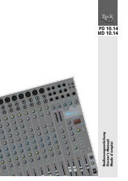
3. Quick reference8 9 1310 6 7 121117 2431451614 5 153Channels1 Channel 1 inputs (XLR female or 1/4")11 Channel 2 volume control2 Channel 2 inputs (XLR female or 1/4")3 Channel 1 outputs (binding-post and Speakon)4 Channel 2 outputs (binding-post and Speakon)5 Bridge output (binding post)6 Signal LED for -40dB to -20dB signal level7 Signal LED for -20dB to 0dB signal level8 Clip LED9 Protection LEDPower amplifier12 Mains on/off switch13 Power LED14 Bridge mode switch15 Ground switch16 Mains input socket17 Automatic fuse10 Channel 1 volume control10Owner`s manual FORCE <strong>180</strong> STAC <strong>Audio</strong>
FORCE <strong>180</strong>4. Connections4.1 Inputs:The inputs CH 1 INPUT (1) and CH 2 INPUT (2)are equipped with XLR/jack compound sockets,wired for balanced operation (see fig.3). Theseinputs must be wired to the outputs of the mixer(e.g. STAC M 810 / EM 810). If needed, more unitslike active crossovers ore equalizers can be addedto the setup by connecting them between mixerand power amplifier.The FORCE <strong>180</strong> offers both XLR and 1/4" inputsfor matching the outputs of other units (see fig.2.1).If the BRIDGE switch (14) of the FORCE <strong>180</strong> hasbeen activated to run the amplifier mono (see alsochapter 5.4), use only the CH 1 INPUT (1).STEREO MODE2 1LRFig. 2.1Inputs4.2 Outputs (Fig. 4):The outputs CH 1 OUTPUT (3) and CH 2 OUTPUT(4) are equipped with Speakon and binding-postconnectors. For stereo operation, either Speakonor binding-post outputs can be used for connectionof speakers (see fig. 4.1 and 4.2), depending onthe connectors used on the speakers. Whenconnecting speakers, always watch for correctpolarity for the left and the right side to avoidsound cancellations. If the amplifier has beenswitched to monaural bridge mode (see chapter5.4), only the BRIDGE output (5) can be used (seefig. 4.3).4.3 Mains supply:Mains connection is provided by a euro-stylemains cable which must be connected to the ACINPUT socket (16). The FORCE <strong>180</strong> is configuredfor 230 VAC / 50Hz mains supply voltage.For overcurrent protection, the FORCE <strong>180</strong> isequipped with a reset-fuse that does not requireone-way fuses. If the automatic fuse is triggered byovercurrent, resetting it brings the FORCE <strong>180</strong>back to operation.BRIDGE MODEFig. 2.2InputsFig. 3LRTIP +RING -Switch position:Sleeve=Ground1 Ground2 +3 -PUSHSTEREOBRIDGEDMONOXLR socket maleXLR socket femaleOwner`s manual FORCE <strong>180</strong> STAC <strong>Audio</strong>11
Fig. 4.1OutputsSTEREO MODE215. Operation5.1 Starting proceduresAfter the FORCE <strong>180</strong> has been connected to themains supply and the other devices according tothe instructions, it is ready for operation. To avoidaccidental feedback which might damage thespeakers, it is advisable to rotate the volumecontrols CHANNEL 1 (10) and CHANNEL 2 (11)fully counterclockwise before switching on theamplifier.After these precautions have been taken, theFORCE <strong>180</strong> is ready to be switched on with thePOWER switch (12). The amplifier is ready foroperation when the LED (13) above the POWERswitch is bright.Speakon pin layout:1+ ⇒1+1- ⇒ 1-Abb. 4.2+-2+ ⇒2- ⇒STEREO MODEBinding-Postnot connected+-5.2 Signal level adjustmentsWith an audio signal connected to the amplifier'sinputs, carefully rotate the volume controlsCHANNEL 1 (10) and CHANNEL 2 (11) clockwiseuntil the SIGNAL LEDs (6 or 7) start flashing. TheCLIP LEDs (8) should just not flash at signalpeaks. With these level adjustments, the overallvolume of the PA system can be adjusted with themaster output faders of the mixing console. Thevolume controls of the FORCE <strong>180</strong> should needreadjustments only when the CLIP LEDs startflashing during operation.Abb. 4.3+-5.3 Ground lift switch (15)Occasionally, a loud hum can be heard after a PAsystem has been switched on, usually as a resultof a 'ground loop' inside your setup. Is this case,using the GROUND switch (15) may interrupt theground loop and stop the hum. In its FRAMEposition, the signal ground is connected to theamplifier's earth (case), in the FLOAT position,signal ground is not connected to earth (see fig.5).If the hum cannot be eliminated this way, contactan authorized STAC dealer for assistance.BRIDGE MODEWiring = red to red+-FLOATGROUNDFRAME+-12Owner`s manual FORCE <strong>180</strong> STAC <strong>Audio</strong>
FORCE <strong>180</strong>5.4 Bridge Mode (Fig. 4.3)When the bridge mode switch (14) is in itsBRIDGED MONO position, both stereo outputamplifiers inside the FORCE <strong>180</strong> are combined formonaural operation, doubling the available outputpower from 300W to 600W. Refer to chapter 4 forcorrect input connections for bridged operation.5.5 Protection functionsA bright PROT LED (9) indicates that one of theFORCE <strong>180</strong>'s internal protection circuits has beenactivated. The reasons could be:- DC voltage at the speaker outputs- Short circuit at one speaker output- Overload of amplifier- Mismatched speaker loadIn this case, switch off the amplifier and check allconnections. If the PROT LED remains bright,contact an authorized STAC dealer.STEREOBRIDGEDMONO5.6 CoolingThe FORCE <strong>180</strong> has two independent cooling fansfor protecting both output amplifiers againstoverheating.Attention: Switching the FORCE <strong>180</strong> to bridgemode also doubles the speaker output impedancefrom 4-8 ohms to 8-16 ohms. For maximum powerefficiency, the total speaker impedance shouldalways equal the amplifier's output impedance.7. TroubleshootingSymptomPOWER LED (13) remains dark afterPOWER switch (12) has been engaged.Problem- Blown house fuse(s). Check and replace fuses.- Internal power supply defective. Contact authorized STACdealer.- Automatic amplifier fuse (17) has been triggered. Reset fuseby pushing button.PROT LED (9) remains brightSIGNAL LED’s (6 oder 7) remain dark andP O W E RL E D(12) is bright.SIGNAL LED’s (6 & 7) are flashing, but no signal isheard.A loud hum is heard through the speakers.- Check speaker cables for short connections.- Check speakers for short connections or incorrect wiring.- Insufficient cooling air supply or amplifier overload.(Contact authorized STAC dealer)- Amplifier defective. (Contact authorized STAC dealer)- Check connections between amplifier inputs and mixer.- Check audio device before amplifier.- Check connections between amplifier outputs and speakercabinets.- Check position of VOLUME controls (10 & 11)- Check speakers for function.- Move ground switch (15) to other position.Owner`s manual FORCE <strong>180</strong> STAC <strong>Audio</strong>13
8. Technical specificationsStereoanwendungOutput power (20Hz-20kHz, THD+N ≤ 0,05%)Stereo into 8 ohms . . . . . . . . . . . . . . . . . . . . . . . . . . . . . . . . . . . .2x 125WStereo into 4 ohms . . . . . . . . . . . . . . . . . . . . . . . . . . . . . . . . . . . . .2x 200WBridge into 8 ohms . . . . . . . . . . . . . . . . . . . . . . . . . . . . . . . . . . . . .1x 400WOutput power (1kHz, THD+N ≤ 0,05%)Stereo into 8 ohms . . . . . . . . . . . . . . . . . . . . . . . . . . . . . . . . . . . . .2x 130WStereo into 4 ohms . . . . . . . . . . . . . . . . . . . . . . . . . . . . . . . . . . . . .2x 220WBridge into 8 ohms . . . . . . . . . . . . . . . . . . . . . . . . . . . . . . . . . . . . .1x 430WDistortion (20Hz-20kHz, 50% output power)Stereo into 8 ohms . . . . . . . . . . . . . . . . . . . . . . . . . . . . . . . . . . . . . 0,03%Stereo into 4 ohms . . . . . . . . . . . . . . . . . . . . . . . . . . . . . . . . . . . . . . 0,05%Bridge into 8 ohms . . . . . . . . . . . . . . . . . . . . . . . . . . . . . . . . . . . . . . . 0,05%Channel seperation (50% output power, 8 ohms)(1kHz, Att. max. input 600 ohms shunt) . . . . . . . . . . . . . . . . . . . . . . 85dBS/N ratio (input 600 ohms shunt) . . . . . . . . . . . . . . . . . . . . . . . . . . . 100dBDamping factor (8 ohms, 1kHz) . . . . . . . . . . . . . . . . . . . . . . . . . . . . . . ≥150Slew rate (stereo & bridge) . . . . . . . . . . . . . . . . . . . . . . . . . . . . .± 40V / µsInput sensitivity . . . . . . . . . . . . . . . . . . . . . . . . . . . . . . . . . . . . . . . . . .0dBmVoltage gain . . . . . . . . . . . . . . . . . . . . . . . . . . . . . . . . . . . . . . . . . . . . .31dBInput impedance . . . . . . . . . . . . . . . . . 20kohms (balanced & unbalanced)Power consumption . . . . . . . . . . . . . . . . . . . . . . . . . . . . . . . . . . . . . .750WMains supply . . . . . . . . . . . . . . . . . . . . . . . . . . . . . . . . . . . . . .230V~, 50HzControl LED`s . . . . . . . . . . . . . . . . . . . . . . . . . . . . . . . . . . . . . .Power (red). . . . . . . . . . . . . . . . . . . . . . . . . . . . . . . . . . . . . . . . . .Protection (red). . . . . . . . . . . . . . . . . . . . . . . . . . . . . . . . . . . . . . . . . . . . . . .Clip (red). . . . . . . . . . . . . . . . . . . . . . . . . . . . . . . . . . . . . . . . . . .Signal (green)Cooling fans . . . . . . . . . . . . . . . . . . . . . . . .(temperature-controlled speed)Dimensions (w x h x d) [mm] . . . . . . . . . . . . . . . . . . . . .482 x 88 x 369mm. . . . . . . . . . . . . .(19“ / 2 rackspace height units)Weight . . . . . . . . . . . . . . . . . . . . . . . . . . . . . . . . . . . . . . . . . . . . . . . . .12kg14Owner`s manual FORCE <strong>180</strong> STAC <strong>Audio</strong>
FORCE <strong>180</strong>Instruction de sécurité1. Lisez attentivement la notice d'utilisation avant toute utilisation.2. Toutes les indications de prévention contenues dans cette notice ou sur l'appareil doivent être suiviesscrupuleusement.3. L'appareil ne doit pas être utilisé à proximité d'eau ( bassine d'eau, baignoire, cave humide, piscine, etc.)4. L'appareil ne doit pas être utilisé à proximité de source de chaleur, un radiateur par exemple.5. Evitez d'exposer l'appareil à la poussière et aux vibrations.6. Il faut éviter l'entrée de tout corps solide ou liquide dans le boîtier.7. N'utiliser que des prises électriques protégées afin d'éviter toute électrocution.8. L'appareil ne doit être utilisé que correctement raccordé à un réseau de terre. En aucun cas la ligne de terre nedoit être interrompue.9. Le câble d'alimentation électrique doit être protégé de toute possibilité de percement, pincement ou cisaillementpar un objet quelconque. Il est particulièrement important d'éviter toute contrainte mécanique aux passages decâbles et à la prise secteur.10. En cas de non utilisation prolongée, débrancher le câble de la prise secteur.11. Eviter l'emploi de supports instables ou inclinés12. Aucune maintenance ou réparation ne doit être effectuée par l'utilisateur. Toute maintenance ou réparation nedoit être effectuée que par un technicien qualifié.13. Conservez ces instructions pour utilisation ultérieure.2. Equipments- Commutable mode stéréo ou ponté- Une diode indiquant un signal de -20 à 0dB, une autrepour signal allant de -40 à -20dB- 2 x 200W dans 4 Ohm en mode stéréo- Une entrée symétrique par XLR (femelle) et par Jackstéréo par canal- 1 x 400W dans 8 Ohm en mode mono- Sortie par bornier et prise SPEAKON- Un ventilateur par canal- Potentiomètre de volume par canal- Mise en route temporisée- Interrupteur de mise sous tension- Diode de surmodulation (CLIP LED)- Diode de mise sous tension- Indicateur de mise en service de protections internes(PROTECT-LED)- Prise pour raccordement secteur 230VAC/50Hz- Protection en sortie contre la composante continue- Centrale de protection- Protection en sortie contre les courts-circuits- Interrupteur de déconnexion de la masse à la terre(GROUND LIFT)- Protection contre les surchargesCâble secteur fourni- Protection contre une désadaptation en sortiemode d’emploiFORCE <strong>180</strong> STAC <strong>Audio</strong>15
3. Aperçu des éléments constitutifs8 9 1310 6 7 121117 2431451614 5 153Canaux1 Entrée canal 1 (XLR femelle ou Jack stéréo)11 Réglage du niveau sonore du canal 22 Entrée canal 2 (XLR femelle ou Jack stéréo)3 Sortie canal 1 (SPEAKON ou bornier)4 Sortie canal 2 (SPEAKON ou bornier)5 Bornier de sortie "en pont" (BRIDGE)6 Diode de signal allant de -40 à -20 dB7 Diode de signal allant de -20 à 0 dB8 Diode de surmodulation (CLIP)9 Diode d'intervention des protections10 Réglage du niveau sonore du canal 1Etage de puissance12 Interrupteur mise sous tension (POWER)13 Diode de mise sous tension (POWER-LED)14 Interrupteur de mise en pont (BRIDGED)15 Interrupteur de déconnexion de la masse à la terre(GROUND LIFT)16 Prise secteur17 Centrale de protection16mode d’emploiFORCE <strong>180</strong> STAC <strong>Audio</strong>
FORCE <strong>180</strong>4. Raccordements4.1 EntréesLes entrées "INPUT CH 1" (1)et "INPUT CH 2" (2)proposent des raccordements symétriques parXLR et 'Jack' stéréos (Fig. 3). Les sortiescorrespondantes de la table de mixage (STACM81 / EM 810 par ex.) sont raccordées à cesentrées. Si nécessaire, d'autres appareils tels quefiltre actif ou égaliseur, peuvent également y êtreraccordé.Quelle que soit la source de signal, chaque canalne doit être alimenté que par l'un ou l'autre desprises d'entrée (Fig. 2.1).Lorsque l'appareil est configuré en monophonie etque l'interrupteur "BRIDGED" (14) est enclenché(voir paragraphe 5.4 : Mode ponté), seule l'entrée"INPUT CH 1" (1) doit être raccordée (Fig. 2.2).MODE STEREO2 1GDFig. 2.1Entrées4.2 Sorties (Fig. 4)Les enceintes sont à raccorder soit aux prises"CH1 OUTPUT" (3) et "CH2 OUTPUT" (4) qui sontde type 'Speakon' ou bornier en mode stéréo (Fig.4.1 et 4.2). On peut donc s'adapter au type deraccordements des enceintes disponibles. Il estégalement primordial de bien surveiller la polaritédes raccordements ( + et - ) entre les différentesenceintes pour éviter un détimbrage par oppositionde phase. En mode 'mono bridgé', les enceintessont à raccorder exclusivement par le bornier "BRIDGE OUTPUT" (5) (Fig. 4.3).4.3 AlimentationsL'alimentation électrique s'effectue via un câble quise raccorde à la prise "MAINS INPUT " (16 ) situéeà l'arrière de l'amplificateur. L'appareil est étudiépour fonctionner avec un secteur établi à 230V/ 50H z .Une centrale de protection (17) est installée afind'éviter la propagation d'un défaut. Ceci évitel'emploi de fusibles. Si la protection s'est mise enmarche et a interrompu l'alimentation, celle-ci doitêtre réenclenchée après suppression de la causedu défaut pour une remise en marche.MODE EN PONT (BRIDGE)Fig. 2.2EntréesFig. 3 Pointe +GDAnneau -Position de l’interrupteurCorps=masse1 masse2 +3 -PUSHSTEREOMONOEN PONTFiche XLR mâlePrise châssis XLR femellemode d’emploiFORCE <strong>180</strong> STAC <strong>Audio</strong>17
Fig. 4.1SortiesMODE STEREO215. Fonctions5.1 Mise en serviceL'amplificateur peut être mis en service aprèsl'avoir convenablement raccordé au réseauélectrique et aux autres éléments restant dusystème électro-acoustique (console de mixage,enceintes, etc.). En premier lieu, faire attention debien positionner les potentiomètres "CHANNEL 1"(10) et "CHANNEL 2" (11). Ceci permet d'éviter lesaccrochages acoustiques (Larsen) qui peuventendommager le système de renforcement sonore.A ce moment, l'amplificateur peut être mis en serviceen actionnant l'interrupteur "POWER" (12). La miseen service est signalée l'allumage de la diode"POWER LED" (13).Câblage Speakon1+ ⇒1+1- ⇒ 1-Fig. 4.2+-2+ ⇒2- ⇒MODE STEREOBorniersnon connecté+-5.2 Contrôle du signal d’entréeMaintenant vous pouvez tourner les potentiomètresde volume "CHANNEL 1" (10) et "CHANNEL 2"(11) vers la droite jusqu'à ce que les diodes"SIGNAL LED" (6 ou 7) pour la zone de - 40dB à -20dB ou de - 20dB à 0dB clignotent. La diode desurmodulation "CLIP" (8) ne devrait pas encores'allumer lors des passages les plus forts. Quandl'amplificateur est ajusté de cette manière, le niveausonore du système de renforcement sonore n'estajusté que par le 'fader' principal de la console demixage. L'ajustage de l'amplificateur ne sera corrigéen principe que si la diode de surmodulation "CLIPLED" (8) s'allume pendant l'utilisation.Fig. 4.3+-+-MODE EN PONTCombinaison de raccordement spéciale5.3 Interrupteur de liaison masse/terre(GROUND LIFT)Un ronflement fort dû a une boucle de masse peutêtre perçu dans le système pendant le fonctionnement.On peut dans ce cas manoeuvrerl'interrupteur "GROUND" (15). S'il est en position"FRAME", la masse signal est reliée à la terre, s'ilest en position "FLOAT", la masse signal estdéconnectée de la terre (Fig. 5). Si l'on n'arrive pasà éliminer le ronflement par ce moyen, il faudrafaire appel à l'intervention d'un technicien agrééSTAC.FLOATGROUNDFRAME+-18mode d’emploiFORCE <strong>180</strong> STAC <strong>Audio</strong>
FORCE <strong>180</strong>5.4 Mode ponté „BRIDGE“ (Fig. 4.3)Les deux amplificateurs sont couplés en pontlorsque l'interrupteur "BRIDGE" (14) est basculé de"STEREO" en "BRIDGED MONO". Ceci double lapuissance, la passant de 200W à 400W. Lesraccordements en mode ponté sont explicités auchapitre 4.STEREOBRIDGEDMONOATTENTION: mis à part la modification depuissance de sortie en mode ponté, l'impédancedu système à raccorder passe également de 4-8Ohm à 8-16 Ohm. Bien vérifier ceci au niveaude l'impédance des enceintes raccordées.5.5 Protections intégréesL'allumage de la diode "PROT-LED" (9) indiquel'activation de protection interne contre :- Tension continue à l'entrée ou à la sortie- Court-circuit en sortie- Surcharge- Mauvaise adaptation en sortieDans ce cas, l'appareil doit être mis hors tensionpour vérifier toutes les connexions. Si aprèsvérification soigneuse et remise en service del'appareil la diode "PROT-LED" reste toujoursallumée, il faudra contacter un revendeur agréeSTAC.5.6 RefroidissementLes deux blocs amplificateurs sont refroidis enpermanence par deux ventilateurs afin d'évitertoute surchauffe.6. Guide de dépannageDéfaut / SymptômeDiode „POWER-LED“ (13) ne s’allume pas malgrél’enclenchement de l’interrupteur „POWER“ (12)Causes ou actions correctrices possibles- Vérifier le raccordement au secteur ainsi que les fusibleset/ou disjoncteurs du réseau- Défaut de l’alimentation interne (se rapprocher d’un revendeuragréé STAC)- Vérifier les protections internes, et au besoin, réenclencher lesystème de protectionLa diode „PROT-LED“ s’allume en rouge après miseen serviceDiodes "SIGNAL-LED" (6 ou 7) ne clignotent pas etaucun signal n'est audible bien que la diode"POWER LED" (12) soit allumée.Diodes „SIGNAL-LED“ (6 ou 7) clignotent mais aucunsignal n’est audible- Vérifier l’existence de court-circuit dans les câbles- Vérifier l’existence de court-circuit ou de mauvais câblage dansles enceintes- Refroidissement insuffisant ou surcharge de l’étage de puissance(se rapprocher d’un revendeur agréé STAC)- Défaut dans l’ètage de puissance(se rapprocher d’un revendeur agréé STAC)- Impédance trop faible par canal ( < 4 Ohms)- Vérifier les connexions entre la console et les entrées del'amplificateur- Vérifier l’appareil connecté en amont- Vérifier les raccordements aux enceintes- Vérifier la position du potentiomètre "VOLUME"- Defaut des enceintesUn ronflement fort est perçu dans le système de - Opérer l’interrupteur „GROUND“ (15)renforcement sonoremode d’emploiFORCE <strong>180</strong> STAC <strong>Audio</strong>19
7. Spécifications techniquesMode stéréoPuissance de sortie (F = 20Hz-20kHz, THD+N ≤ 0,05%)Mode stéréo Rcharge = 8Ohm . . . . . . . . . . . . . . . . . . . . . . . . . . .2x 125WMode stéréo Rcharge = 4 Ohm . . . . . . . . . . . . . . . . . . . . . . . . . . .2x 200WMode ponté, Rcharge = 8 Ohm . . . . . . . . . . . . . . . . . . . . . . . . . . .1x 400WPuissance de sortie (F = 1kHz, THD+N ≤ 0,05%)Mode stéréo, Rcharge = 8 Ohm . . . . . . . . . . . . . . . . . . . . . . . . . . .2x 130WMode stéréo, Rcharge = 4 Ohm . . . . . . . . . . . . . . . . . . . . . . . . . . .2x 220WMode ponté, Rcharge = 8 Ohm . . . . . . . . . . . . . . . . . . . . . . . . . . .1x 430WDistorsions (F = 20Hz-20kHz, demi-puissance)Mode stéréo, Rcharge = 8 Ohm . . . . . . . . . . . . . . . . . . . . . . . . . . .≤ 0,03%Mode stéréo, Rcharge = 4 Ohm . . . . . . . . . . . . . . . . . . . . . . . . . . .≤ 0,05%Mode ponté, Rcharge = 8 Ohm . . . . . . . . . . . . . . . . . . . . . . . . . . . .≤ 0,05%Diaphonie à demi-puissance, Rcharge = 8 Ohm(F = 1kHz, ATT. max. et entrée avec shunt de 600 Ohm) . . . . . . . .≤ 85dBRapport signal/bruit avec entrée shuntée à 600 Ohm . . . . . . . . . .≤ 100dBFacteur d’amortissement Rcharge = 8 Ohm, F = 1kHz . . . . . . . . . . . .≥ 150Vitesse de balayage en mode stéréo et ponté . . . . . . . . . . . . . .± 40V / usSensibilité d’entrée . . . . . . . . . . . . . . . . . . . . . . . . . . . . . . . . . . . . . . .0dBmGain en tension . . . . . . . . . . . . . . . . . . . . . . . . . . . . . . . . . . . . . . . . . .31dBImpédance d’entrée (symétrique et asymétrique) . . . . . . . . . . . . .20kOhmConsommation . . . . . . . . . . . . . . . . . . . . . . . . . . . . . . . . . . . . . . . . . .750WSecteur . . . . . . . . . . . . . . . . . . . . . . . . . . . . . . . . . . . . . . . . . .230V~, 50HzDiodes électroluminescentes (LED) . . . . . . . . . . . . . .1x puissance = rouge. . . . . . . . . . . . . . . . . . . . . . . . . . . . . . . . . . . . .2x protection = rouge. . . . . . . . . . . . . . . . . . . . . . . . . . . . . . . . . . . . . .2x surmodul = rouge. . . . . . . . . . . . . . . . . . . . . . . . . . . . . . . . . . . . . . . . .4x signal = verteVentilateurs . . . . . . . . . . . . . . . . . . . . . . .Vitesse asservie à la températureDimensions (L x H x P) [mm] . . . . . . . . . . . . . . . . . . . . .482 x 88 x 369mm. . . . . . . . . . . . . . . . . . . . . . . . . . . . . . .(19“ / 2U)Masse . . . . . . . . . . . . . . . . . . . . . . . . . . . . . . . . . . . . . . . . . . . . . . . . . .12kgby <strong>Zeck</strong> <strong>Audio</strong> • Turnhallenweg 6 • D 79183 Waldkirch • Phone +49(0)7681/2004-0 • Fax +49(0)7681/2004-43e-mail: <strong>Zeck</strong>.<strong>Audio</strong>@t-online.de • http//www.<strong>Zeck</strong><strong>Audio</strong>.de