RFU1718 - VETUS.com
RFU1718 - VETUS.com
RFU1718 - VETUS.com

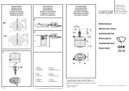
You also want an ePaper? Increase the reach of your titles
YUMPU automatically turns print PDFs into web optimized ePapers that Google loves.
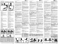
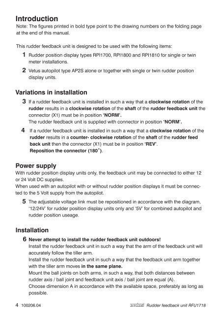
IntroductionNote: The figures printed in bold type point to the drawing numbers on the folding pageat the end of this manual.This rudder feedback unit is designed to be used with the following items:1 Rudder position display types RPI1700, RPI1800 and RPI1810 for single or twinmeter installations.2 Vetus autopilot type AP2S alone or together with single or twin rudder positiondisplay units.Variations in installation3 If a rudder feedback unit is installed in such a way that a clockwise rotation of therudder results in a clockwise rotation of the shaft of the rudder feedback unit theconnector (X1) must be in position ‘NORM’.The rudder feedback unit is supplied with connector in position ‘NORM’.4 If a rudder feedback unit is installed in such a way that a clockwise rotation of therudder results in a counter- clockwise rotation of the shaft of the rudder feedback unit then the connector (X1) must be in position ‘REV’.Reposition the connector (180˚).Power supplyWith rudder position display units only, the feedback unit may be connected to either 12or 24 Volt DC supplies.When used with an autopilot with or without rudder position displays it must be connectedto the 5 Volt supply from the autopilot.5 The adjustable voltage link must be repositioned in accordance with the diagram,‘12/24V’ for rudder position display units only and ‘5V’ for <strong>com</strong>bined autopilot andrudder position useage.Installation6 Never attempt to install the rudder feedback unit outdoors!Install the rudder feedback unit in such a way that the arm of the feedback unit willaccurately follow the tiller arm.Install the rudder feedback unit in such a way that the feedback unit arm togetherwith the tiller arm moves in the same plane.Mount the ball joints on both arms, in such a way, that both distances betweenrudder axis / ball joint and feedback unit axis / ball joint are equal (A).Choose dimension A in accordance with the available space, preferably as long aspossible. 100206.04Rudder feedback unit <strong>RFU1718</strong>