1 reductores ortogonales serie a helical bevel gear units series a ...
1 reductores ortogonales serie a helical bevel gear units series a ...
1 reductores ortogonales serie a helical bevel gear units series a ...

Create successful ePaper yourself
Turn your PDF publications into a flip-book with our unique Google optimized e-Paper software.
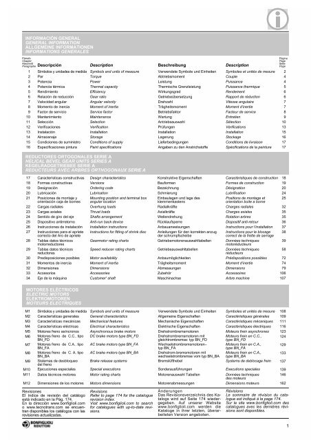
INFORMACIÓN GENERALGENERAL INFORMATIONALLGEMEINE INFORMATIONENINFORMATIONS GENERALESPárrafoChapterAbschnittParagrapheDescripción Description Beschreibung Description1 Símbolos y unidades de medida Symbols and <strong>units</strong> of measure Verwendete Symbole und Einheiten Symboles et unités de mesure 22 Par Torque Abtriebsmoment Couple 43 Potencia Power Leistung Puissance 44 Potencia térmica Thermal capacity Thermische Grenzleistung Puissance thermique 55 Rendimiento Efficiency Wirkungsgrad Rendement 66 Relación de reducción Gear ratio Getriebeübersetzung Rapport de réduction 67 Velocidad angular Angular velocity Drehzahl Vitesse angulaire 78 Momento de inercia Moment of inertia Trägheitsmoment Moment d’inertie 79 Factor de servicio Service factor Betriebsfaktor Facteur de service 810 Mantenimiento Maintenance Wartung Entretien 911 Selección Selection Antriebsauswahl Sélection 1012 Verificaciones Verification Prüfungen Vérifications 1313 Instalación Installation Installation Installation 1514 Almacenaje Storage Lagerung Stockage 1615 Condiciones de suministro Conditions of supply Lieferbedingungen Conditions de livraison 1716 Especificaciones pintura Paint specifications Angaben zu den Anstrichstoffe Spécifications de la peinture 17REDUCTORES ORTOGONALES SERIE AHELICAL BEVEL GEAR UNITS SERIES AKEGELRADGETRIEBEE SERIE AREDUCTEURS AVEC ARBRES ORTHOGONAUX SERIE A17 Características constructivas Design characteristics Konstruktive Eigenschaften Caractéristiques de construction 1818 Formas constructivas Versions Bauformen Formes de construction 1919 Designación Ordering code Bezeichnung Désignation 2020 Lubricación Lubrication Schmierung Lubrification 2421 Posiciones de montaje y Mounting position and terminal box Einbaulagen und lage desPositions de montage et 25orientación caja de bornes angular locationklemmenkastensorientation boite a borne22 Cargas radiales Overhung loads Radialkräfte Charges radiales 3223 Cargas axiales Thrust loads Axialkräfte Charges axiales 3524 Sentido de giro del eje Shafts arrangement Wellendrehung Rotation arbres 3525 Dispositivo antirretorno Anti-run back device Rücklaufsperre Dispositif anti-retour 3626 Instrucciones de instalación Installation instructions Anbauanweisungen Instructions pour l’installation 3727 Instrucciones para el apriete Instructions for fitting of shrink disc Anleitungen für den korrekten anzug Instructions pour le blocage 38correcto del Aro de aprieteder schrumpfscheibecorrect de la frette de serrage28 Tablas datos técnicos Gearmotor rating charts Getriebemotorenauswahltabellen Données techniques39motor<strong>reductores</strong>motoréducteurs29 Tablas datos técnicos Speed reducer rating charts Getriebeauswahltabellen Données techniques58<strong>reductores</strong>réducteurs30 Predisposiciones posibles Motor availability Anbaumöglichkeiten Prédispositions possibles 7231 Momentos de inercia Moment of inertia Trägheitsmoment Moment d’inertie 7432 Dimensiones Dimensions Abmessungen Dimensions 7933 Accesorios Accessories Zubehör Accessoires 10634 Eje de la máquina Customer' shaft Maschinachse Arbre machine 107PáginaPageSeitePageMOTORES ELÉCTRICOSELECTRIC MOTORSELEKTROMOTORENMOTEURS ELECTRIQUESM1 Símbolos y unidades de medida Symbols and <strong>units</strong> of measure Verwendete Symbole und Einheiten Symboles et unités de mesure 108M2 Características generales General characteristics Allgemeine Eigenschaften Caractéristiques générales 109M3 Características mecánicas Mechanical features Mechanische Eigenschaften Caractéristiques mécaniques 111M4 Características eléctricas Electrical characteristics Elektrische Eigenschaften Caractéristiques électriques 116M5 Motores freno asíncronos Asynchronous brake motors Drehstrombremsmotoren Moteurs frein asynchrones 123M6 Motores freno de C.C.. tipoBN_FDDC brake motors type BN_FDDrehstrombremsmotoren mitgleichtrombremse: typ BN_FDMoteurs frein en C.C.,type BN_FD124M7 Motores freno de C.A.. tipoBN_FAAC brake motors type BN_FAWechselstrombremsmotoren–typ BN_FAMoteurs frein en C.A.,type BN_FA129M8 Motores freno de C. A. tipoBN_BAAC brake motors type BN_BADrehstrom-bremsmotoren mitwechselstrombremse vom typ BN_BAMoteurs frein en C.A.,type BN_BA133M9 Sistemas de desbloqueodel frenoBrake release systems Bremslüfthebel Systems de deblocage frein 137M10 Ejecuciones especiales Special executions Sonderausführungen Executions speciales 139M11 Datos técnicos motores Motor rating charts Motorenauswahl Tabellen Données techniques146des moteursM12 Dimensiones de los motores Motors dimensions Motorenabmessungen Dimensions moteurs 162RevisionesEl índice de revisión del catálogoestá indicado en la Pág. 174.En la dirección www.bonfiglioli.como www.tecnotrans.com se encuentrandisponibles los catálogos con lasrevisiones actualizadas.RevisionsRefer to page 174 for the cataloguerevision index.Visit www.bonfiglioli.com to searchfor catalogues with up-to-date revisions.ÄnderungenDas Revisionsverzeichnis des Katalogswird auf Seite 174 wiedergegeben.Auf unserer Websitewww.bonfiglioli.com werden dieKataloge in ihrer letzten, überarbeitetenVersion angeboten.RévisionsLe sommaire de révision du catalogueest indiqué à la page 174.Sur le site www.bonfiglioli.com descatalogues avec les dernières révisionssont disponibles.1
INFORMACION GENERALGENERAL INFORMATION ALLGEMEINEINFORMATIONEN INFORMATIONS GENERALES2 - PAR2 - TORQUE2 - ABTRIEBSMOMENT2 - COUPLEPar nominalM n2 [Nm]Rated torqueM n2 [Nm]Nenn-DrehmomentM n2 [Nm]Couple nominalM n2 [Nm]Es el par transmisible en la salidacon carga continua uniforme,referido a la velocidad deentrada n 1 y a la correspondientevelocidad de salida n 2 .Se calcula sobre la base de unfactor de servicio f s =1.The torque that can be transmittedcontinuously through theoutput shaft, with the <strong>gear</strong> unitoperated under a service factorf s =1.Rating is speed sensitive.Dies ist das an der Abtriebswelleübertragbare Drehmomentbei gleichförmiger Dauerbelastungbezogen auf die Antriebsdrehzahln 1 und die entsprechendeAbtriebsdrehzahl n 2 .Das Drehmoment wird aufGrundlage eines Betriebsfaktorf s = 1 berechnet.C’est le couple transmissible ensortie avec une charge continueuniforme se référant à la vitesseen entrée n 1 et à cellecorrespondante en sortie n 2 .Il est calculé sur la base d’unfacteur de service f s =1.Par resistenteM r2 [Nm]Required torqueM r2 [Nm]Verlangtes DrehmontM r2 [Nm]Couple requisM r2 [Nm]Representa el par solicitado porla aplicación concreta y deberáser siempre igual o menor queel par de salida nominal M n2 delreductor seleccionado.The torque demand based onapplication requirement.It must always be equal to orless than torque M n2 the <strong>gear</strong>boxunder study is rated for.Dies ist das von der Anwendungverlangte Drehmoment,das stets kleiner oder gleichdem Nenn-Abtriebsmoment M n2des gewählten Getriebes seinmuß.Il représente le couple requispar l’application et devra toujoursêtre inférieur ou égal aucouple en sortie nominal M n2 duréducteur choisi.Par de cálculoM c2 [Nm]Calculated torqueM c2 [Nm]Soll-DrehmomentM c2 [Nm]Couple de calculM c2 [Nm]Es el valor del par que se utilizapara la selección del reductorconsiderando el par solicitadoM r2 y el factor de servicio f s yseobtiene con la formula:Computational torque value tobe used when selecting the<strong>gear</strong>box.It is calculated considering therequired torque M r2 and servicefactor f s , as per the equationhere after:Dies ist das bei der Wahl desGetriebes zugrundezulegendeDrehmoment, wobei das übertrageneDrehmoment M r2 undder Betriebsfaktor f s zu berücksichtigensind; das Soll-Drehmomentwird mit folgenderGleichung berechnet:C’est la valeur de couple à utiliserpour la sélection du réducteuren considérant le couplerequis M r2 et le facteur de servicefs et s’obtient avec la formule:M c2 =M r2 ·f s
La relación de intermitencia(I)% se obtiene a partir de la relaciónentre el tiempo de funcionamientoen carga t f y el tiempototal (t f +t f ), expresado en porcentaje.Where cyclic duration factor(I)% is the relationship of operatingtime under load t f to totaltime (t f + t r ) expressed as apercentage.Wobei die Einschaltdauer (I)%von dem Verhältnis zwischenBetriebszeit unter Last tf undder Gesamtbetriebszeit (t f +t r ),ausgedrückt in Prozenten, gegebenwird.Où le degré d’intermittence (I)%est fourni par le rapport entre letemps de fonction en charge etle temps total (t f +t r ) exprimé enpourcentage.t fI=t + tfr· 100 (2)Deberá cumplirse la condición: The condition to be verified is: Die durchzuführende Kontrolleist:La vérification à faire sera lasuivante:P r1 P t f t (3)5 - RENDIMIENTO5 - EFFICIENCY5 - WIRKUNGSGRAD5 - RENDEMENTRendimiento dinámico dDynamic efficiency dDynamischer Wirkungsgrad dRendement dynamique dViene dado por la relación entrela potencia de salida P 2 ylapotenciade entrada P 1 , según larelación:Obtained from the relationshipof delivered power P 2 to inputpower P 1 , according to the followingequation:Er ist gegeben durch das Verhältnisder Abtriebsleistung P 2zur Antriebsleistung P 1 :Il est donné par le rapport entrela puissance en sortie P 2 etcelle en entrée P 1 : d P P21· 100 [%] (4)(A3)2x 3x 4x d 94% 91% 89%6 - RELACIÓN DE REDUCCIÓN i6 - GEAR RATIO i6 - GETRIEBEÜBERSETZUNG i6 - RAPPORT DE REDUCTION iEl valor de la relación de reducciónde la velocidad, identificadopor el símbolo [ i ], secalcula a partir de la velocidadde entrada n 1 y de la velocidadde salida n 2 utilizando la expresiónsiguiente:The value for the <strong>gear</strong> ratio isreferred to with the letter [ i ]and calculated through the relationshipof the input speed n 1 tothe output speed n 2 :Die Übersetzung des Getriebeswird mit dem Buchstaben [ i ]bezeichnet und ist folgendermaßendefiniert:Le rapport de réduction estidentifiée par la lettre [i]etsoncalcul s’effectue à partir de lavitesse d’entrée n 1 et de la vitessede sortie n 2 en utilisant larelation suivante :i= n n12(5)6
En el catálogo, la relación dereducción es normalmente, unnúmero con un sólo decimal oninguno si i > 1000.Si se precisa conocer el númerocompleto con todos los decimales,consúltese el ServicioTécnico de Bonfiglioli Riduttori.The <strong>gear</strong> ratio is usually a decimalnumber which in this catalogueis truncated at one digitafter the comma (no decimalsfor i > 1000).If interested in knowing the exactvalue please consultBonfiglioli’s Technical Service.In diesem Katalog wird dieÜbersetzung mit einer Stellehinter dem Komma angegeben,bei Übersetzungen > 1000ohne Dezimalstelle.Wenn genaue Angaben zurÜbersetzung benötigt werden,wenden sie sich bitte an dentechnischen Service von BonfiglioliRiduttori.Dans le catalogue, le rapport deréduction a une précision d’unchiffre après la virgule (saufpour i > 1000).Si une plus grande précision estnécessaire, contacter le ServiceTechnique de Bonfiglioli.7 - VELOCIDAD ANGULAR7 - ANGULAR VELOCITY7 - DREHZAHL7 - VITESSE ANGULAIREVelocidad a la entradan 1 [min -1 ]Input speedn 1 [min -1 ]Drehzahl Antriebswellen 1 [min -1 ]Vitesse d' entréen 1 [min -1 ]Es la velocidad correspondienteal tipo de motorización seleccionado;los valores de catálogose refieren a las velocidadesde los motores eléctricos desimple y doble polaridad utilizadoshabitualmente.Si el reductor es accionado porun mecanismo de transmisión ala entrada, es preferible utilizarvelocidades inferiores a 1400r.p.m. con el fin de garantizarcondiciones optimas de funcionamiento.Se admiten velocidades a la entradasuperiores, teniendo encuenta la natural disminucióndel par nominal M n2 del reductor.The speed is related to theprime mover selected. Cataloguevalues refer to speed ofeither single or double speedmotors that are common in theindustry.If the <strong>gear</strong>box is driven by anexternal transmission it is recommendedto operate it with aspeed of 1400 min -1 , or lower,in order to optimise operatingconditions and lifetime.Higher input speeds are permitted,however in this case considerthat torque rating M n2 isaffected adversely.Please consult a Bonfiglioli representative.Dies ist die vom gewählten Motortypabhängige Drehzahl. DieKatalogangaben beziehen sichauf die Drehzahl von allgemeinüblicheneintourigen Elektromotorenoder von polumschatbarenElektromotoren.Um optimale Betriebsbedingungenzu gewährleisten, ist stetseine Antriebsdrehzahl unter1400 min -1 zu empfehlen.Höhere Antriebsdrehzahlen sindzulässig, wobei die zwangsläufigeHerabsetzung des Nenn-AbtriebsdrehmomentsM n2 des Getriebeszu berücksichtigen ist.C’est la vitesse relative au typede motorisation choisie. Les valeursde catalogue se réfèrentaux vitesses des moteurs électriquesà simple et double polaritécommunément utilisés.Si le réducteur reçoit le mouvementd’une transmission enentrée, il est toujours préférabled’adopter des vitesses inférieuresà 1400 min -1 afin de garantirdes conditions optimales defonctionnement.Des vitesses d’ entrée supérieuressont admises en considérantle déclassement natureldu couple nominal M n2 du réducteur.Velocidad a la salidan 2 [min -1 ]Output speedn 2 [min -1 ]Abtriebsdrehzahln 2 [min -1 ]Vitesse en sortien 2 [min -1 ]Se obtiene a partir de la velocidada la entrada n 1 y de la relaciónde reducción i, según laecuación:The output speed value n 2 iscalculated from the relationshipof input speed n 1 to the <strong>gear</strong> ratioi, as per the following equation:Sie ist abhängig von der Antriebsdrehzahln 1 und dem Übersetzungsi nach folgenderGleichung:Elle varie en fonction de la vitessed’entrée n 1 et du rapportde reduction i selon l’équation:n2= n i1(6)8 - MOMENTO DE INERCIAJ r [Kgm 2 ]8 - MOMENT OF INERTIAJ r [Kgm 2 ]8 - TRÄGHEITSMOMENTJ r [Kgm 2 ]8 - MOMENT D'INERTIEJ r [Kgm 2 ]Los momentos de inercia indicadosen el catálogo se refierenal eje de entrada del reductorpor lo que, en el caso de acoplamientodirecto, ya están referidosa la velocidad del motor.Moments of inertia specified inthe catalogue refer to the <strong>gear</strong>unit input axis. They are thereforerelated to motor speed, inthe case of direct motor mounting.Die im Katalog angegebenenTrägheitsmomente sind auf dieAntriebswelle des Getriebes bezogenund daher im Falle einerdirekten Verbindung schon zurMotordrehzahl in Beziehung gesetzt.Les moments d’inertie indiquésdans le catalogue se réfèrent àl’axe d’entrée du réducteur parconséquent, dans le cas d’accouplementdirect, ils se rapportentdéjà à la vitesse dumoteur.7
9 - FACTOR DE SERVICIO f s9 - SERVICE FACTOR f s9 - BETRIEBSFAKTOR f s9 - FACTEUR DE SERVICE f sEl factor de servicio es el parámetroque traduce a un valornumérico la dificultad del servicioa que el reductor estará solicitado,teniendo en cuenta,con inevitable aproximación, elfuncionamiento diario, las variacionesde la carga y las posiblessobrecargas, conjuntamentecon la aplicación específicadel reductor.En el gráfico (A4) abajo expuesto,el factor de servicio seobtiene después de haber seleccionadola columna correspondientea las horas defuncionamiento diarias, por intersecciónentre el número dearranques / horas y una de lascurvas (K1, K2, K3).Las curvas K_ están asociadasa la naturaleza del servicio(aproximadamente: uniforme,medio y pesado) a través delfactor de aceleración de lasmasas K, ligado a la relaciónentre las inercias de las masasconducidas y el motor.Independientemente del valordel factor de servicio así obtenido,destacamos que existenaplicaciones entre las cuales,como por ejemplo la elevaciónde cargas, para las que la roturade un elemento del reductor,podría representar un riesgo delesiones del personal que opereen las proximidades.En caso de dudas de la aplicaciónconcernientes a los posiblesriesgos, aconsejamosconsultar previamente connuestro Servicio Técnico.This factor is the numeric valuedescribing reducer service duty.It takes into consideration, withunavoidable approximation,daily operating conditions, loadvariations and overloads connectedwith reducer application.In the graph (A4) below, afterselecting proper “daily workinghours” column, the service factoris given by intersecting thenumber of starts per hour andone of the K1, K2 or K3 curves.K_ curves are linked with theservice nature (approximately:uniform, medium and heavy)through the acceleration factorof masses K, connected to theratio between driven massesand motor inertia values.Regardless of the value givenfor the service factor, we wouldlike to remind that in some applications,which for exampleinvolve lifting of parts, failure ofthe reducer may expose the operatorsto the risk of injuries.If in doubt, please contact ourTechnical Service Department.Beim Betriebsfaktor handelt essich um den Parameter, der dieBetriebsbelastung, die das Getriebeaushalten muss, in einemWert ausdrückt. Dabei berücksichtigter, auch wenn nur mit einerunvermeidbaren Annäherung,den täglichen Einsatz, dieunterschiedlichen Belastungenund eventuelle Überbelastungen,die mit der spezifischen Applikationdes Getriebes verbundensind. Der nachstehenden Grafik(A4) kann, nach der Wahl derentsprechenden Spalte mit derAngabe der täglichen Betriebsstundender Betriebsfaktor entnommenwerden, indem man dieSchnittstelle zwischen der stündlichenSchaltungen und einer derKurven K1, K2 und K3 sucht. Diemit K_ gekennzeichneten Kurvensind über den Beschleunigungsfaktorder Massen K an die Betriebsartgekoppelt (annähernd:gleichmäßige, mittlere oder starkeBelastung), der wiederum andas Verhältnis zwischen Trägheitsmomentder angetriebenenMassen und dem des Motors gebundenist. Unabhängig von demso erhaltenen Betriebsfaktor,möchten wir Sie darauf hinweisen,dass es Applikationen gibt,unter denen beispielsweise auchdie Hebefunktionen zu findensind, bei denen das Nachgebeneines Getriebeorgans, das indessen Nähe arbeitende Personaleiner Verletzungsgefahr aussetzenkönnte. Sollten daherZweifel darüber bestehen, ob dieentsprechende Applikation sichin diesem Bezug als kritisch erweist,bitten wir Sie sich zuvor mitunseren Technischen Kundendienstin Verbindung zu setzen.Le facteur de service est le paramètrequi traduit en une valeurnumérique la difficulté duservice que le réducteur est appeléà effectuer en tenantcompte, avec une approximationinévitable, du fonctionnementjournalier, de la variabilitéde la charge et des éventuellessurcharges liées à l’applicationspécifique du réducteur.Sur le graphique (A4) ci-dessous,le facteur de service peutêtre trouvé, après avoir sélectionnéla colonne relative auxheures de fonctionnement journalier,à l’intersection entre lenombre de démarrages horaireset l’une des courbes K1, K2et K3.Les courbes K_ sont associéesà la nature du service (approximativement: uniforme, moyenet difficile) au moyen du facteurd’accélération des masses K,lié au rapport entre les inertiesdes masses conduites et le moteur.Indépendamment de la valeurdu facteur de service ainsitrouvée, nous signalons qu’ilexiste des applications parmilesquelles, à titre d’exemple, leslevages, pour lesquels la ruptured’un organe du réducteurpourrait exposer le personneopérant à proximité immédiateà des risques de lésion.En cas de doute concernant lesrisques éventuels de l’application,nous vous conseillons decontacter préalablement notreService Technique.(A4)8
Factor de aceleración de lasmasas, KAcceleration factor ofmasses, KBeschleunigungsfaktorder Massen, KFacteur d’accélérationdes masses, KEl parámetro sirve para la seleccionarla curva correspondientea un determinado tipo decarga. El valor se obtiene de larelación:This parameter serves for selectingthe right curve for thetype of load. The value is givenby the following ratio:Dieser Parameter dient derWahl der Kurve, die sich auf diejeweilige Belastungsart bezieht.Der Wert ergibt sich aus folgenderFormel:Le paramètre sert à sélectionnerla courbe relative au typede charge particulier. La valeurest obtenue par l’équation :K= J cJm(7)donde:J c momento de inercia de lasmasas conducidas, referidoal eje del motormomento de inercia del motorJ mwhere:J c moment of inertia of drivenmasses referred to motordriving shaftmoment of inertia of motorJ mwobei:J c Trägheitsmoment der angetriebenenMassen, bezogenauf die MotorwelleTrägheitsmoment des MotorsJ moù:J c moment d’inertie des massescommandées se référantà l’arbre du moteurmoment d’inertie du moteurJ mK 0.25 – curva K1carga uniformeK 0.25 – curve K1uniform loadK 0.25 – Kurve K1Gleichmäßige BelastungK 0.25 – courbe K1charge uniforme0.25 < K 3 – curva K2carga con choques moderados0.25 < K 3 – curve K2moderate shock load0.25 < K 3 – Kurve K2Belastung mit mäßigenStößen0.25 < K 3 – courbe K2charge avec chocs modérés3 10,nous vous conseillons decontacter notre Service Technique.10 - MANTENIMIENTO10 - MAINTENANCE10 - WARTUNG10 - ENTRETIENLos <strong>reductores</strong> suministradoscon lubricación permanente nonecesitan sustituciones periódicasdel aceite.Para los otros tipos se recomiendauna primera sustitucióndel lubricante una vez transcurridaslas primeras 300 horas defuncionamiento, procediendo aun cuidadoso lavado interno conlos detergentes adecuados.Evitar la mezcla de aceites mineralescon aceites sintéticos.Controlar periódicamente el niveldel lubricante efectuando lasustitución indicados en los intervalosindicados en la tabla(A5).Life lubricated <strong>gear</strong>boxes do notrequire any periodical oilchanges.For other types of <strong>gear</strong>boxes,the first oil change must takeplace after about 300 hours ofoperation, carefully flushing the<strong>gear</strong> unit using suitable detergents.Do not mix mineral oils withsynthetic oils.Check oil level regularly andchange oil at the intervalsshown in the table (A5).Die mit Dauerschmierung geliefertenGetriebe bedürfen periodischeÖlwechsel.Bei den übrigen Getrieben wirdein erster Ölwechsel nach ca.300 Betriebsstunden empfohlen,wobei das Innere der Gruppesorgfältig mit einemgeeigneten Reinigungsmittel zuwaschen ist.Mineralöle nicht mit Syntheseölenmischen.Den Ölstand regelmäßig kontrollieren.Die Ölwechsel in denin der Tabelle (A5) angegebenenFristen durchführen.Les réducteurs fournis avec lubrificationpermanente n’ont besoind’aucun remplacementpériodique de huile.Pour les autres, nous conseillonsd’effectuer une première vidangedu lubrifiant après les300 premières heures de fonctionnementen réalisant un lavagesoigné à l’intérieur dugroupe avec des produits détergentsappropriés. Eviter de mélangerles huiles à baseminérale avec des huiles synthétiques.Contrôler périodiquementle niveau du lubrifiant eneffectuant les vidanges conformèmentaux intervalles indiquésdans le tableau (A5).(A5)Temperatura aceite / Oil temperatureÖltemperatur / Température huile[°C]Aceite mineral / mineral oilMineralöl / huile minéraleIntervalo de lubricación / Oil change intervalSchmierfrist / Intervalle de lubrification[h]Aceite sintético / synthetic oilSyntheseöl / huile synthétique< 65 8000 2500065 - 80 4000 1500080 - 95 2000 125009
11 - SELECCIÓN11 - SELECTION11 - ANTRIEBSAUSWAHL11 - SELECTIONPara seleccionar correctamenteun reductor o un motor<strong>reductores</strong> necesario disponerde algunos datos fundamentalesque hemos resumido en latabla (A6).A discreción del cliente, esta tablapodrá ser cumplimentada yremitida a nuestro Servicio Técnicoque se encargará de la selecciónde la motorización másadecuada para la aplicación indicada.(A6)Some fundamental data arenecessary to assist the correctselection of a <strong>gear</strong>box or<strong>gear</strong>motor. The table below(A6) briefly sums up this information.To simplify selection, fill in thetable and send a copy to ourTechnical Service which will selectthe most suitable drive unitfor your application.Um die Getriebe und Getriebemotorenrichtig auszuwählen zukönnen, muß man über einigegrundlegende Daten verfügen,die wir in der Tabelle (A6) zusammengefaßthaben.Eine Kopie dieser vom Kundenausgefüllten Tabelle kann anunseren Technischen Kundendienstgeschickt werden, derdann die für die gewünschteAnwendung geeignete Auslegungwählt.Pour sélectionner correctementun réducteur ou un motoréducteur,il est nécessaire de disposerde certaines donnéesfondamentales que nous avonsrésumé dans le tableau (A6).En particulier, ce dernier pourraêtre rempli et retourné à notreservice technique qui rechercherala motorisation la plusappropriée à l’application indiquée.Tipo de aplicaciónType of applicationAnwendungType d'applicationP r2 Potencia de salida a n 2 máxOutput power at n 2 maxAbtriebsleistung bei n 2 maxPuissance en sortie à n 2 maxi....................kWP r2 ‘ Potencia de salida a n 2 mínOutput power at n 2 minAbtriebsleistung bei n 2 minPuissance en sortie à n 2 mini....................kWM r2 Par torsor de salida a n 2 máxOutput torque at n 2 maxAbtriebsdrehmoment bei n 2 maxMoment de torsion en sortie à n 2 maxi....................Nmn 2 Velocidad de giro a la salida máxMax.output speedAbtriebsdrehzahl maxVitesse de rotation maxi en sortie ....................min -1n 2‘n 1n 1‘Velocidad de giro a la salida mínMin.output speedAbtriebsdrehzahl minVitesse de rotation mini en sortie ....................min -1Velocidad de giro a la entrada máxMax.input speedAntriebsdrehzahl maxVitesse de rotation maxi en entrée ....................min -1Velocidad de giro a la entrada mínMin.input speedAntriebsdrehzahl minVitesse de rotation mini en entrée ....................min -1R c2 Carga radial sobre el eje de salidaRadial load on output shaftRadialkraft auf AbtriebswelleCharge radiale sur arbre de sortie....................Nx 2 Distancia de aplicación de la carga ( *)Load application distance ( *)Abstand des Kraftangriffspunktes ( *)Distance d’application de la charge ( *)....................mmOrientación de la carga a la salidaLoad orientation at outputOrientierung der Last am AbtriebOrientation de la charge en sortie ...........Sentido de giro del eje de salida (O-AO) ( **)Output shaft rotation direction (CW-CCW) ( **)Drehrichtung der Abtriebswelle (U-GU) ( **)Sens de rotation arbre sortie (H-AH) ( **) ....................R c1 Carga radial sobre el eje de entradaRadial load on input shaftRadialkraft auf AntriebswelleCharge radiale sur arbre d’ entrée....................Nx 1 Distancia de aplicación de la carga ( *)Load application distance ( *)Abstand des Kraftangriffspunktes ( *)Distance d’application de la charge ( *)....................mmOrientación de la carga el eje de entradaLoad orientation at inputOrientierung der Last am AntriebOrientation de la charge en entrée ..........Sentido de giro del eje de entrada (O-AO) ( **)Input shaft rotation direction (CW-CCW) ( **)Drehrichtung der Antriebswelle (U-GU) ( **)Sens de rotation arbre entrée (H-AH) ( **...................A c2A c1 Carga axial sobre el eje de salida (+/–)( ***)Thrust load on output shaft (+/–)( ***)Axialkraft auf Abtriebswelle (+/–)( ***)Charge axiale sur arbre de sortie (+/–)( ***)...................NA c1 Carga axial sobre el eje a la entrada (+/–)( ***)Thrust load on input shaft (+/–)( ***)Axialkraft auf Antriebswelle (+/–)( ***)Charge axiale sur arbre d’ entrée (+/–)( ***)...................NJc Momento de inercia de la cargaMoment of inertia of the loadTrägheitsmoment der LastMoment d’inertie de la charg .................Kgm 2t aZM bTemperatura ambienteAmbient temperatureUmgebungstemperaturTempérature ambianteElevación sobre el nivel del marAltitude above sea levelHöhe ü.d.M.Altitude au-dessus du niveau de la merTipo de servicio según normas CEIDuty type to IEC normsRelative Einschaltdauer gemäß CEIType de service selon CEFrecuencia de arranqueStarting frequencySchaltungshäufigkeitFréquence de démarrageTensión de alimentación del motorMotor voltageNennspannung des MotorsTension de alimentation moteurTensión de alimentación del frenoBrake voltageNennspannung der BremseTension de alimentation freinFrecuenciaFrequencyFrequenzFréquencePar de frenadoBrake torqueBremsmomentCouple de freinagGrado de protección del motorMotor protection degreeSchutzart des MotorsDegré de protection moteur...................C°...................mS........../......%...................1/h...................V...................V...................Hz...................NmIP..................Clase de aislamientoInsulation classIsolierstoffklasseClasse d’isolation ......................(*) La distancia x1-2 es la comprendidaentre el punto de aplicaciónde la fuerza y el apoyo deleje. (Si no se indica, se considerarála fuerza que actúa sobreel punto medio de la parteexterna del eje).(** ) O = HorarioAO = Anti - horario(*** ) + – = = compresióntracción(*) Distance x1-2 is between forceapplication point and shaft shoulder(if not indicated the forceacting at mid-point of the shaftextension will be considered).(**) CW = clockwise;CCW = counterclockwise(*** ) + – = = pullpush(*) Der Abstand x1-2 ist der Abstandvom Kraftangriffspunkt zumWellenansatz (wenn nicht andersangegeben, wird davonausgegangen, daß die Kraft aufder Mitte des Wellenendes angreift).(** ) U = Uhrzeigersinn;GU = Gegenuhrzeigersinn(*** ) + – = = ZugDruck(*) La distance x1-2 est celle compriseentre le point d’applicationde la force et l’épaulement del’arbre (si non precisée l’onconsiderera la force agissant aumilieu de la saillie de l’arbre).(**) H = sens horaire;AH = sens antihoraire(*** ) + – = = tractioncompression10
Selección de los motor<strong>reductores</strong>Selection of a <strong>gear</strong>motorWahl des GetriebemotorsSélection des motoréducteursa) Determinar el factor de serviciof s en función del tipo decarga (factor K), del númerode arranques por hora Z r ydel numero de horas de funcionamiento.a) Determine service factor f saccording to type of duty(factor K), number of startsper hour Z r and hours of operation.a) Den Betriebsfaktor f s in Abhängigkeitvon der Belastungsart(Faktor K), denSchaltungen /Stunde Z r undden Betriebs stunden bestimmen.a) Déterminer le facteur deservice f s en fonction dutype decharge (facteur K),du nombre d’insertions/heureZ r et du nombre d’heuresde fonctionnement.b) A partir del par M r2 , conociendon 2 , y el rendimientodinámico d , calcular la potenciade entrada.b) From values of torque M r2 ,speed n 2 and efficiency dthe required input power canbe calculated from the equation:b) Aus dem Drehmoment M r2mit ilfe der bekannten Wertefür n 2 und dem dynamischenWirkungsgrad d dieAntriebsleistung ableiten.b) A partir du couple M r2 , enconnaissant n 2 et le rendementdynamique d , calculerla puissance en entrée.P = M n •r19550r2 2• d[kW] (8)El valor de d para el reductoren cuestión se obtienecon las indicaciones del párrafo5.c) Buscar en las tablas de datostécnicos de los motor<strong>reductores</strong>la que corresponda a unapotencia normalizada P n :Value of d for the captionedworm <strong>gear</strong> can be sortedout from paragraph 5.c) Consult the <strong>gear</strong>motor selectioncharts and locate thetable corresponding to normalisedpower P n :Für das spezifische Getriebekann der Wert d unterParagraph 5 erhoben werden.c) Unter den Tabellen mitden Technischen Daten derGetriebemotoren die Tabelleauswählen, die folgenderLeistung entspricht:Il valeur de d pour le réducteurspécifique peut être calculéed’après les indicationsdu paragraphe 5.c) Rechercher parmi les tableauxdes caractéristiquestechniques des motoréducteurscelui correspondant àune puissance:P n P r1(9)Si no se indica lo contrario,la potencia P n de los motoresindicada en el catálogo,se refiere al servicio continuoS1.Para los motores utilizadosen condiciones distintas deS1, será necesario identificarel tipo de servicio previstode acuerdo con lasnormas CEI 2-3/IEC 34-1.En particular, para serviciosde S2 a S8 y para tamañosde motores iguales o inferioresa 132, es posible obtenerun incremento de lapotencia con respecto a laprevista para el serviciocontinuo. Por lo tanto, lacondición a satisfacer será:Unless otherwise specified,power P n of motors indicatedin the catalogue refersto continuous duty S1.For motors used inconditions other than S1,the type of duty required byreference to CEI 2-3/IEC34-1 Standards must bementioned.For duties from S2 to S8 inparticular and for motorframe 132 or smaller, extrapower output can be obtainedwith respect to continuousduty.Accordingly the followingcondition must be satisfied:Wenn nicht anders angegeben,bezieht sich die im Katalogangegebene LeistungP n der Motoren auf DauerbetriebS1. Bei Motoren, dieunter anderen Bedingungenals S1 eingesetzt werden,muß die vorgesehen Betriebsartunter Bezug auf dieCEI-Normen 2-3/IEC 34-1bestimmt werden.Insbesondere kann man fürdie Betriebsarten S2 bis S8(und für Motorbaugrößengleich oder niedriger als132) eine Überdimensionierungder Leistung relativ zuder für den Dauerbetriebvorgesehenen Leistung erhalten;die zu erfüllende Bedingungist dann:Sauf indication contraire lapuissance P n des moteursindiquée dans le cataloguese réfère à un service continuS1.Pour les moteurs utilisésdans des conditions différentesdu service S1, il seranécessaire d’identifier letype de service prévu en seréférant aux normes CEI2-3/IEC 34-1.En particulier, pour les servicesde type S2 à S8 ou pourles tailles de moteurs égalesou inférieures à 132 il estpossible d’obtenir une majorationde la puissance parrapport à celle prévue pourle service continu. Parconséquent, la condition àsatisfaire sera:PnPr1 (10)fmEl factor de incremento f mobtiene de la tabla (A7).seThe adjusting factor f m can beobtained from table (A7).Der Überdimensionierungsfaktorf m kann der Tabelle (A7) entnommenwerden.Le facteur de majoration f m peutêtre obtenu en consultant le tableau(A7).11
Relación de intermitenciaIntermittence ratioRelative EinschaltdauerRapport d’intermittencet fI=t + tfr. 100 (11)t f =t r =tiempo de funcionamientoa carga constantetiempo de reposot f =work time at constant loadt r= rest timet f = Betriebszeit mit konstanterBelastungt r = Aussetzzeitt f =t r =temps de fonctionneentà charge constantetemps de repos(A7)SERVICIO / DUTY / BETRIEB / SERVICES2 S3* S4 - S8Duración del ciclo / Cycle duration [min]Relación de intermitencia / Cyclic duration factor (I)Zyklusdauer / Durée du cycle [min]Relative Einschaltdauer / Rapport d’intermittence (l)Contacte con nosotrosPlease contact us10 30 60 25% 40% 60%RückfrageNous contacterfm 1.35 1.15 1.05 1.25 1.15 1.1* La duración del ciclo deberáser, no obstante, igual o inferiora 10 minutos. Si fuese superior,consulte con nuestro ServicioTécnico.* Cycle duration, in any event,must be 10 minutes or less.If it is longer, please contact ourTechnical Service.* Die Zyklusdauer muß in jedemFall kleiner oder gleich 10min sein; wenn sie darüberliegt, unseren Technisch enKundendienst zu Rate ziehen.* La durée du cycle devra êtreégale ou inférieure à 10 minutes.Si supérieure, contacternotre Service Technique.En la sección correspondientea la potencia instalada P n ,seleccionaren esta el reductor oel motorreductor que desarrollela velocidad de funcionamientomas próxima a la velocidad n 2deseada y para la cual el factorde seguridad S sea igual o superioral factor de servicio f s .El factor de seguridad se obtienesegún la formula (12):Next, refer to the appropriate P nsection within the <strong>gear</strong>motor selectioncharts and locate theunit that features the desiredoutput speed n 2 , or closest to,along with a safety factor S thatmeets or exceeds the applicableservice factor f s .The safety factor is so defined:Als nächstes wählen Sie anhandder Getriebemotoren auswahltabellenden Abschnitt mitder entsprechenden P n und suchendie gewünschte Abtriebsdrehzahln 2 , oder die nächstmöglicheDrehzahl, zusammenmit dem Sicherheitsfaktor S, derden zutreffenden Betriebsfaktorf s erreicht oder überschreitet.Der Sicherheitsfaktor wird wiefolgt berechnet:Dans la section relative à la puissanceinstallée P n sélectionner enfinle motoréducteur qui développela vitesse de fonctionnement laplus proche à la vitesse n 2 désiréeet pour lequel le facteur de sécuritéS soit pareil, ou supérieur, aufacteur de service f s .Le facteur de sécurité est définiainsi:S= MnM22= PnP11(12)Las tablas de datos técnicos delos motor<strong>reductores</strong> se refieren ala velocidad de motores de 2, 4 y6 polos alimentados a 50 Hz.Si se prevé la utilización de motorescon velocidades distintasa las indicadas, la selección deberárealizarse de acuerdo conel procedimiento de selecciónde <strong>reductores</strong>.As standard, <strong>gear</strong> and motorcombinations are implementedwith 2, 4 and 6 pole motors, 50Hz supplied.Should the drive speed be differentfrom 2800, 1400 or 900min-1, base the selection on the<strong>gear</strong> unit nominal rating.Standardmäßig stehen Getriebemotorenkombinationenmit 2,4 und 6 poligen Motoren füreine Frequenz von 50 Hz zurVerfügung. Sollten die Antriebsdrehzahlenabweichend von2800, 1400 oder 900 min-1sein, dann stützen Sie die Auslegungdes Getriebes auf dieGetriebenenndaten.Dans les tableaux de sélectiondes motoréducteurs les accouplementssont développés avecmoteurs à 2, 4 et 6 poles alimentésà 50 Hz. Pour vitessesde commande différentes à celles-ci,sélectionner suite auxdonnées nominales fourniespar les réducteurs.Selección de <strong>reductores</strong> y <strong>reductores</strong>predispuestos paramotores IECSelection of speed reducerand <strong>gear</strong>box with IEC motoradapterWahl des Getriebes und Getriebefür IEC-motorenSélection des réducteurs etdes réducteurs CEIa) Determinar el factor de serviciof s .b) Conociendo el par de salidaM r2 de salida requerido porla aplicación, se procede ala definición del par decálculo:a) Determine service factor f s .b) Assuming the requiredoutput torque for the applicationM r2 is known, thecalculation torque can bethen defined as:a) Den Betriebsfaktor f s bestimmen.b) Anhand des bekannten vonder Anwendung gefordertenAbtriebsdrehmoments M r2das Soll-Drehmoment bestimmen:a) Déterminer le facteur deservice f s .b) En connaissant le coupleM r2 de sortie requis parl’application, l’on procède àla définition du couple decalcul:M c2 =M r2 ·f s (13)12
c) A partir de la velocidad a lasalida n 2 requerida y la de laentrada n 1 disponible, secalcula la relación de reducción:c) The <strong>gear</strong> ratio is calculatedaccording to requested outputspeed n 2 and drivespeed n 1 :c) Auf Grundlage der verlangtenAbtriebsdrehzahl n 2 und derverfügbaren Antriebsdrehzahln 1 die Übersetzungs berechnen:c) Suivant la vitesse en sortien 2 requise et celle enentrée n 1 disponible, l’oncalcule le rapport de réduction:i= n n1(14)2Disponiendo de los datos deM c2 y de i, se buscará en lastablas correspondientes a lavelocidad n 1 el reductorque, en función de la relaciónde reducción [i] máspróxima a la calculada, tengaun par nominal:Once values for M c2 and iare known consult the ratingcharts under the appropriateinput speed n 1 and locatethe <strong>gear</strong> unit thatfeatures the <strong>gear</strong> ratio closestto [i] and at same timeoffers a rated torque valueM n2 so that:Anhand der Werte für M c2und i in den Tabellen für dieDrehzahl n 1 das Getriebeauswählen, das in Abhängigkeitvon einer Übersetzung [i],die dem Sollwert möglichstnahe ist, folgendes Nenn-Drehmomenterlaubt:En disposant des donnéesM c2 et i, l’on recherchera dansles tableaux correspondant àla vitesse n 1 le réducteur qui,en fonction du rapport [i] leplus proche de celui calculé,propose un couple nominal:M n2 M c2 (15)Si al reductor seleccionadodebe acoplarse un motoreléctrico, verificar la compatibilidadconsultando la tablade las predisposiciones posibles,párrafo 30.If a IEC normalized motormust be fitted check geometricalcompatibility withthe <strong>gear</strong> unit at paragraph30 - Motor availability.Wenn das Getriebe mit einemElektromotor verbundenwerden soll, dieVerträglichkeit anhand derTabelle der möglichen Anbaumöglichkeitensicherstellen.Au cas où il serait nécessaired’appliquer un moteur électriquenormalisé au réducteurchoisi, en vérifier la possibleadaptation en consultant letableau des prédispositionspossibles présenté.12 - VERIFICACIONES12 - VERIFICATION12 - PRÜFUNGEN12 - VERIFICATIONSUna vez realizada la seleccióndel reductor, o motorreductor,se recomienda efectuar las siguientesverificaciones:After the selection of the speedreducer, or <strong>gear</strong>motor, is completeit is recommended thatthe following verifications areconducted:Nachdem die Auswahl des Getriebeoder Getriebemotor abgeschlossenist, werden diefolgenden Schritte empfohlen:Une fois effectuée la sélectiondu réducteur, ou motoréducteur,il faut procéder aux suivantesvérifications:a) Potencia térmicaAsegurarse que la potenciatérmica del reductor tengaun valor igual o mayor a lapotencia requerida por laaplicación según la ecuación(3) en la Pág. 6; en casocontrario, seleccionar unreductor de tamaño superioro bien prever un sistema derefrigeración forzada.a) Thermal capacityMake sure that the thermalcapacity of the <strong>gear</strong>box isequal to or greater than thepower required by the applicationaccording to equation(3) on page 6.If this condition is not verified,select a larger <strong>gear</strong>boxor apply a forced coolingsystem.a) Thernische GrenzleistungSicherstellen, daß die Wärmeleistungdes Getriebesgrößer oder gleich der verlangtenLeistung ist, die vonder Anwendung nach Gleichung(3) auf S. 6 verlangtwird. Andernfalls ein größerdimensioniertes Getriebewählen bzw. ein Zwangskühlsystemvorsehen.a) Puissance thermiqueS’assurer que la puissancethermique du réducteur aitune valeur supérieure ouégale à la puissance requisepar l’application selonl’équation (3) page 6. Dansle cas contraire, sélectionnerun réducteur de taillesupérieure ou bien prevoirun système de refroidissementforcé.b) Par máximoEn general, el par máximo(entendido como pico de cargainstantáneo) aplicable alreductor no deberá superarel 200 % del par nominalM n2 ; por lo tanto, verificarque este límite no sea superado,adoptando si fuese necesario,los dispositivosadecuados para la limitacióndel par.b) Maximum torqueThe maximum torque (intendedas instantaneouspeak load) applicable to the<strong>gear</strong>box must not, in general,exceed 200% of rated torqueM n2 . Therefore, check thatthis limit is not exceeded, usingsuitable torque limitingdevices, if necessary.For three-phase doublespeed motors, it is importantb) Max. DrehmomentIm allgemeinen darf dasmax. Drehmoment (verstandenals mom entane Lastspitze),das auf das Getriebeaufgebracht werdenkann, 200 % des NenndrehmomentsM n2 nicht überschreiten.Sicherstellen, daßdieser Grenzwert nicht überschrittenwird, und nötigenfallsdie entsprechendenb) Couple maximumGénéralement, le couple maximum(à considerer commeune pointe de charge instantanée)applicable au réducteurne doit pas dépasser les200% du couple nominal M n2 .Verifier par conséquent quecette limite ne soit pas dépasséeen adoptant, si nécessaire,des dispositifs adaptéspour limiter le couple.13
Para los motores trifásicosde doble polaridad es necesarioprestar especial atenciónal par de conmutacióninstantáneo que se generadurante la conmutación dealta a baja velocidad, ya queeste valor puede ser decididamentemás alto que elmismo par máximo.Un método simple y económicode reducir dicho parconsiste en alimentar sólodos fases del motor durantela conmutación (el tiempo dealimentación a dos fasespuede ser regulado a travésde un relé temporizado):to pay attention to theswitching torque which isgenerated when switchingfrom high to low speed, becauseit could be significantlyhigher than maximumtorque.A simple, economical way tominimize overloading is topower only two phases ofthe motor during switch-over(power-up time on twophases can be controlledwith a time-relay):Vorrichtungen zur Begrenzungdes Drehmoments vorsehen.Bei polumschaltbaren Drehstrommotorenmuss demUmschaltdrehmoment, dasbeim Umschalten von derhohen auf die niedrige Drehzahlerzeugt wird, besondereAufmerksamkeit geschenktwerden, da es entschiedengrößer sein kann als dasNenn-Drehmoment.Eine einfache und kostengünstigeMethode zum Senkendieses Drehmomentsbesteht darin, daß nur zweiPhasen des Motors währenddes Umschaltens gespeistwerden (die Dauer der Speisungvon nur 2 Phasen kanndurch ein Zeitrelais gesteuertwerden):Pour les moteurs triphasés àdouble polarité, il est nécessairede prêter une attentionparticulière au couple decommutation instantané quiest généré lors du passagede la grande à la petite vitesseétant donné qu’il peutêtre considérablement plusélevé que le couple maximumlui même.Une méthode simple et économiquepour réduire cecouple consiste à alimenterseulement deux phases dumoteur pendant la commutation(la durée d’alimentationsur deux phases peut êtreréglée au moyen d’un relaistemporisateur):M g2 = 0.5 · M g3M g2 = Par de conmutación alimentando2 fasesM g3 = Par de conmutación alimentando3 fasesEn todo caso, se recomiendacontactar nuestro ServicioTécnico.M g2 = 0.5 · M g3M g2 = Switching torque with twophasepower-upM g3 = Switching torque withthree-phase power-upWe recommend, in anyevent, to contact our TechnicalService.M g2 = 0.5 · M g3M g2 = Umschaltdrehmoment beiSpeisung von 2 Phasen;M g3 = Umschaltdrehmomentbei Speisung von 3 PhasenWir empfehlen jedoch injedem Fall, unseren TechnischenKundendienst zuRate zu ziehen.M g2 = 0.5 · M g3M g2 = Couple de commutation enalimentant deux phasesM g3 = Couple de commutationen alimentant trois phasesNous suggérons cependantde contacter notre ServiceTechnique.c) Cargas radialesVerificar que las cargas radialesque actúan sobre losejes de entrada y/o salidase encuentren dentro de losvalores de catálogo admitidos.Si son superiores, aumentarel tamaño delreductor o modificar el apoyode las cargas.Recordamos que todos losvalores indicados en el catálogose refieren a cargasaplicadas en el punto mediode la parte externa del ejepor lo que, en fase de verificación,es indispensable teneren cuenta estacondición procediendo a determinar,en caso necesario,con las fórmulas adecuadas,la carga admisible a ladistancia x 1-2 deseada.Véanse los párrafos correspondientesa las cargas radiales.c) Radial loadsMake sure that radial forcesapplying on input and/oroutput shaft are withinpermittend catalogue values.If they were higher considerdesigning a different bearingarrangement beforeswitching to a larger <strong>gear</strong>unit.Catalogue values for ratedoverhung loads refer tomid-point of shaft understudy.Should application point ofthe overhung load be localisedfurther out the revisedloading capability must beadjusted as per instructionsgiven in this manual. Seeparagraph 22.c) RadialkräfteSicherstellen, daß die aufdie Antriebswellen und/oderAbtriebswellen wirkendenRadialkräfte innerhalb derzulässigen Katalogwerte liegen.Wenn sie höher sind,das Getriebe größer dimensionierenbzw. die Abstützungder Last verändern.Wir erinnern daran, daß alleim Katalog angegebenenWerte sich auf Kräfte beziehen,die auf die Mitte desWellenendes wirken. DieseTatsache muß bei der Prüfungunbedingt berücksichtigtwerden und nötigenfallsmuß mit Hilfe der geeignetenFormeln die zulässigeKraft beim gewünschten Abstandx 1-2 bestimmt werden.Siehe hierzu die Erläuterungenzu den Radialkräften indiesem Katalog.c) Charges radialesVérifier que les charges radialesagissant sur les arbresd’entrée et/ou de sortiese situent dans les valeursde catalogue admises. Si ellessont supérieures, choisirla taille du réducteur superieureou modifier la reprisede charge. Rappelons quetoutes les valeurs indiquéesdans le catalogue se réfèrentà des charges agissantau milieu de la longueur disponiblede l’arbre contrôlé.Par conséquent, en phasede vérification, il est indispensablede prendre enconsidération cette conditionen déterminant, si nécessaire,avec les formulesappropriées, la charge admissibleà la distance x 1-2désirée. Se rapporter à cepropos aux paragraphes relatifsaux charges radiales.d) Cargas axialesTambién, las eventualescargas axiales deben sercomparadas con las admisibles.En el caso de cargasaxiales muy elevadas ocombinadas con cargas radiales,se recomienda consultarcon nuestro ServicioTécnico.d) Thrust loadsActual thrust load must befound within 20% of theequivalent overhung loadcapacity.Should an extremely high,or a combination of radialand axial load apply, consultBonfiglioli TechnicalService.d) AxialkräfteAuch die eventuell vorhandenenAxialkräfte müssenmit den im Katalog angegebenenzulässigen Wertenverglichen werden. Wennsehr hohe Axialkräfte wirkenoder Axialkräfte in Kombinationmit Radialkräften, bitteunseren Technischen Kundendienstzu Rate ziehen.d) Charges axialesLes éventuelles chargesaxiales devront être comparéesavec les valeurs admissibles.Si l’on est enprésence de charges axialestrès élevées ou combinéesavec des chargesradiales, nous conseillonsd’interpeller notre ServiceTechnique.14
e) Arranques / horaPara servicios diferentes deS1, con un número destacadode arranques / hora sedeberá tener en cuenta unfactor Z (determinable conlas indicaciones presentesen el capítulo de motores)que define el número máximode arranques específicopara la aplicación requerida.e) Starts per hourFor duties featuring a highnumber of switches the actualstarting capability inloaded condition [Z] must becalculated.Actual number of starts perhour must be lower thanvalue so calculated.e) Schaltungen/StundeBei anderen Betriebsartenals S1 mit einem hohenWert für die Schaltungen/Stundemuß der FaktorZ berücksichtigt werden (erkann mit Hilfe der Angabenim Kapitel Motoren bestimmtwerden), der diemax. zulässige Anzahl vonSchalten für eine bestimmteAnwendung definiert.e) Démarrages/heurePour les services différentsde S1, avec un nombre importantd’insertions/heure, ilfaudra prendre en considérationun facteur Z (déterminéà l’aide des informationsreportées dans le chapitredes moteurs) qui définit lenombre maximum de démarragesspécifique pourl’application concernée.13 - INSTALACIÓN13 - INSTALLATION13 - INSTALLATION13 - INSTALLATIONEs muy importante para la instalacióndel reductor, atenersea las siguientes normas:The following installation instructionsmust be observed:Für die Installation des Getriebesist es äußerst wichtig, daßfolgende Normen beachtet werden:Il est très important, pourl’installation du réducteur, de seconformer aux règles suivantes:a) Asegurarse de que la fijacióndel reductor sea establepara evitar vibraciones.Instalar (si se prevé choques,sobrecargas prolongadaso posibles atascos)acoplamientos hidráulicos,embragues, limitadores depar, etc.a) Make sure that the <strong>gear</strong>boxis correctly secured toavoid vibrations.If shocks or overloads areexpected, install hydrauliccouplings, clutches, torquelimiters, etc.a) Sicherstellen, daß die Befestigungdes Getriebes stabilist, damit keine Schwingungenentstehen. Wenn esvoraussichtlich zu Stößen,längerdauernden Überlastenoder zu Blockierungenkommen kann, sind entsprechendeSchutzelemente wiehydraulische Kupplungen,Kupplungen, Rutschkupplungenusw. zu installieren.a) S’assurer que la fixationdu réducteur soit stable afind’éviter toute vibration.Installer (en cas de chocs,de surcharges prolongéesou de blocages) des coupleurshydrauliques, desembrayages, des limiteursde couple etc...b) En fase de pintura se deberánproteger las superficiesmecanizadas y el labio externode los retenes paraevitar que la pintura resequela goma, perjudicandola estanqueidad del propioretén.b) Before being paint coated,the machined surfaces andthe outer face of the oilseals must be protected toprevent paint drying out therubber and jeopardising thesealing function.b) Beim Lackieren die bearbeitetenFlächen und dieDichtringe schützen, damitder Anstrichstoff nicht demKunststoff angreift und somitdie Dichtigkeit der Ölabdichtungenin Frage gestelltwird.b) En phase de peinture, il faudraprotéger les plans usinéset le bord extérieur desbagues d’étanchéité pouréviter que la peinture nedessèche le caoutchouc, cequi risque de nuire àl’efficacité du joint.c) Los elementos que van acopladosa los ejes de salidadel reductor deben ser mecanizadoscon toleranciaISO H7 para evitar (ajustesforzados) bloqueos excesivos,durante la fase demontaje que podrían producirdaños irreparables en elpropio reductor. Para elmontaje y desmontaje de dichoselementos se recomiendael empleo detirantes y extractores adecuados,utilizando el taladroroscado presente en los extremosde los ejes.c) Parts fitted on the <strong>gear</strong>boxoutput shaft must be machinedto ISO H7 toleranceto prevent interference fitsthat could damage the <strong>gear</strong>boxitself. Further, to mountor remove such parts, usesuitable pullers or extractiondevices using the tappedhole located at the top of theshaft extension.c) Die Organe, die mit einerKeilverbindung auf der Abtriebswelledes Getriebesbefestigt werden, müssenmit einer Toleranz ISO H7<strong>gear</strong>beitet sein, um allzufest blockierte Verbindungenzu vermeiden, die eventuellzu einer irreparablenBeschädigung des Getriebeswährend des Einbausführen könnten. Außerdemsind beim Ein- und Ausbaudieser Organe geeigneteZugstangen und Abzieherzu verwenden, wobei dieGewindebohrung an denKopfen der Wellen zu verwendenist.c) Les organes qui sont caléssur les arbres de sortie duréducteur doivent être réalisésavec une tolérance ISOH7 pour éviter les accouplementstrop serrés qui, enphase de montage, pourraientendommager irrémédiablementle réducteur. Enoutre, pour le montage et ledémontage de ces organes,nous conseillons d’utiliserun outillage et des extracteursappropriés en utilisantle trou taraudé situé en extremitéd’ arbre.d) Las superficies de contactodeberán estar limpias y sertratadas con los adecuadosproductos protectores antesdel montaje, para evitar laoxidación y el consiguientebloqueo de las piezas.d) Mating surfaces must becleaned and treated withsuitable protective productsbefore mounting to avoidoxidation and, as a result,seizure of parts.d) Die Berührungsflächen müssensauber sein und vor derMontage mit einem geeignetenSchutzmittel behandeltwerden, um Oxidierung unddie daraus folgende Blockierungder Teile zu verhindern.d) Les surfaces de contact devrontêtre propres et traitéesavec des produits de protectionsappropriés avant lemontage afin d’éviterl’oxydation et par suite leblocage des pièces.15
e) Antes de la puesta en marchadel reductor, verificarque la maquina que lo incorporaesté conforme a lasdisposiciones de la DirectivaMáquinas 89/392 y sucesivasactualizaciones.e) Prior to putting the <strong>gear</strong> unitinto operation make surethat the equipment that incorporatesthe same complieswith the currentrevision of the Machines Directive89/392.e) Bevor das Getriebe im Betriebzu setzen, muß mansich vergewissern daß diedas Getriebe einbauendeMaschine gemäß den aktuellenRegelungen der MaschineRichtlinie 89/392 ist.e) Avant la mise en service duréducteur, vérifier que lamachine où il est monté estconforme aux normes de laDirective Machines 89/392et ses mises à jour.f) Antes de la puesta en marchade la maquina, asegurarseque la posición del nivelde lubricante esté conformea la posición de montaje delreductor y que la viscosidadsea la adecuada al tipo decarga (ver tabla B3).f) Before starting up the machine,make sure that oillevel conforms to the mountingposition specified for the<strong>gear</strong> unit.f) Vor Inbetriebnahme derMaschine sicherstellen, daßdie Anordnung der Füllstandschraubeder Einbaulageangemessen ist, unddie Viskosität des Schmiermittelsder Belastungsartentspricht (siehe TabelleB3).f) Avant la mise en marche dela machine, s’assurer que laposition du niveau du lubrifiantsoit conforme à la positionde montage duréducteur et que la viscositésoit appropriée au type decharge (voir tableau B3).g) En el caso de instalaciónal aire libre es necesarioaplicar protecciones adecuadascon la finalidad deevitar la exposición directaa los agentes atmosféricosy a la radiación solar.g) For outdoor installation provideadequate guards in orderto protect the drive fromrainfalls as well as directsun radiation.g) Bei Inbetriebnahme inFrein, muß man geeignetenSchutzgeräte vorsehen, umdas Antrieb gegen Regenund direkte Sonnenstrahlungzu schutzen.g) En cas d’installation enplein air, il est nécessaired’appliquer des protectionset/ou des caches appropriésde façon à éviter l’expositiondirecte aux agents atmosphériqueset aux rayonnementssolaires.14 - ALMACENAJE14 - STORAGE14 - LAGERUNG14 - STOCKAGEPara un correcto almacenaje delos productos recibidos es necesariorespetar las reglas siguientes:Observe the following instructionsto ensure correct storageof the products:Die korrekte Lagerung der Antriebeerfordert folgende Vorkehrungen:Un correct stockage des produitsreçus nécessite de respecterles règles suivantes:a) Excluir las zonas al aire libre,zonas expuestas a laintemperie o con excesivahumedad.a) Do not store outdoors, in areasexposed to weather orwith excessive humidity.a) Die Produkte nicht im Freienlagern und nicht in Räumen,die der Witterung ausgesetztsind, oder eine hoheFeuchtigkeit aufweisen.a) Exclure les zones à ciel ouvert,les zones exposéesaux intempéries ou avec humiditéexcessive.b) Evitar el contacto directocon el pavimento interponiendosiempre bases demadera o similares.b) Always place boards, woodor other material betweenthe products and the floor.The <strong>gear</strong>boxes should nothave direct contact with thefloor.b) Die Produkte nie direkt aufdem Boden, sondern aufUnterlagen aus Holz odereinem anderen Material lagern.b) Interposer dans tous les casentre le plancher et les produitsdes planches de boisou des supports d’autre natureempêchant le contactdirect avec le sol.c) Para periodos de almacenajeprolongados, las superficiesde unión como bridas,ejes y acoplamientos deberánprotegerse con productosantioxidantes adecuados(Mobilarma 248 o equivalente).En este caso, los <strong>reductores</strong>deberán ser posicionadoscon el tapón respiradero enla posición más alta y llenadostotalmente de aceite.Antes de su puesta en marcha,los <strong>reductores</strong> deberárestablecerse el nivel con lacorrecta cantidad y el tipode lubricante.c) In case of long-term storageall machined surfaces suchas flanges, shafts and couplingsmust be coated witha suitable rust inhibitingproduct (Mobilarma 248 orequivalent).Furthermore <strong>gear</strong> <strong>units</strong>must be placed with the fillplug in the highest positionand filled up with oil.Before putting the <strong>units</strong> intooperation the appropriatequantity, and type, of oilmust be restored.c) Bei anhaltenden Lager-undHaltszeiten müssendie Oberflächen für dieVerbindung, wie Flansche,Wellen oder Kupplungenmit einem geeigneten Oxidationsschutzmittelbehandeltwerden (Mobilarma248 oder ein äquivalentesMittel).Übrigens müssen die Getriebemit nach oben gehrichteterEntlüftungsschraubegelagert und mitÖl gefüllt werden.Die Getriebe müssen vorihrer Verwendung mit derangegeben Menge desvorgesehenen Schmiermittelsgefüllt werden.c) Pour une stockage de longdurée il faut protéger lessurfaces d‘accouplement(brides, arbres, manchond‘accouplement) avec produitanti oxydant (Mobilarma248 ou equivalent).Dans ce cas les réducteursdevront être placés avecbouchon reniflard vers lehaut et complétement replid‘huile.Avant de la mise en servicedu réducteur, la bon quantitéd‘huile devrà etre rétabliselon la quantité indiqué surle catalogue.16
15 - CONDICIONES DESUMINISTRO15 - CONDITIONS OF SUPPLY15 - LIEFERBEDINGUNGEN15 - CONDITIONS DELIVRAISONLos <strong>reductores</strong>como sigue:se suministranGear <strong>units</strong> are supplied as follows:Die Getriebe werden in folgendemZustand geliefert:Les réducteurs sont livréscomme suit:a) Preparados para su instalaciónen la posición de montajeespecificada en elpedido.a) configured for installationin the mounting positionspecified when ordering;a) schon bereit für die Montagein der bei Bestellungfestgelegten Einbaulage;a) déjà prédisposés pour êtreinstallés dans la position demontage comme défini enphase de commande;b) Verificados de acuerdo conlas especificaciones internas.b) tested to manufacturer specifications;b) nach werksinternen Spezifikationengeprüft;b) testés selon les spécificationsinternes;c) Con las superficies de acoplamientosin pintar.c) mating machined surfacescome unpainted;c) die Verbindungsflächen sindnicht lackiert;c) les surfaces de liaison nesont pas peintes;d) Equipados con las tuercas yespárragos de montaje previstospara el montaje demotores (versión IEC).d) nuts and bolts for mountingmotors are provided;d) ausgestattet mit Schraubenund Muttern für die Montageder Motoren (Version mitAdapter für IEC-Motoren);d) équipés d’écrous et de boulonspour le montage desmoteurs normalisés pour laversion CEI;e) Equipados con proteccionesde material plástico en losejes.e) shafts are protected duringtransportation by plasticcaps;e) alle Getriebe werden mitKunststoffschutz auf denWellen geliefert;e) embouts de protections enplastique sur les arbres;f) Equipados con cáncamosde suspensión (cuando corresponda).f) supplied with lifting lug(where applicable).f) mit Transportierring zum Anheben (falls vorgesehen).f) dotés d’un crochet de levage(quand cela est prévu).16 - ESPECIFICACIONES DEPINTURA16 - PAINT SPECIFICATIONS16 - ANGABEN ZU DENANSTRICHSTOFFE16 - SPECIFICATIONS DELA PEINTURELas especificaciones de las pinturasaplicadas sobre los <strong>reductores</strong>(cuando corresponda)podrán ser solicitadas a las filialeso a los distribuidores quehayan suministrado los equipos.Specifications for paint appliedto <strong>gear</strong>boxes (where applicable)may be obtained from thebranches or dealers that suppliedthe <strong>units</strong>.Die Spezifikationen des Lackes,der auf den Getriebe (wo erforderlich)verwendet wurde, könnenbei den Filialen oderVerkaufsstellen, die die Gruppengeliefert haben, angefordertwerden.Les spécification de la peintureappliquée sur les réducteurspourront, le cas échéant, êtredemandées aux filiales ou auxdistributeurs ayant fourni lesgroupes.17
17 - CARACTERISTICAS DEDISEÑO17 - DESIGNFEATURES17 - KONSTRUKTIVEEIGENSCHAFTEN17 - CARACTERISTIQUESDE CONSTRUCTIONLas principales característicasde diseño son:• modularidad• diseño compacto• montajes universales• rendimientos elevados• bajo nivel de rumorosidad• engranajes de acero aleado,cementados y templados• cajas de aluminio sin pintaren las dimensiones 10, 20,30y de fundición de alta resistencia,pintadas, para lasotras dimensiones• ejes de entrada y salida deacero de alta resistencia.The main design characteristicsare:• modularity• space effective• universal mounting• high efficiency• quite operation• <strong>gear</strong>s in hardened and case-hardenedsteel• bare aluminium housing forsizes 10, 20, 30, unpaintedhigh strength painted cast-ironhousings for larger framesizes• input and output shafts fromhigh grade steel.Die wichtigsten konstruktivenEigenschaften sind:• Baueinheitensystem• Kompaktheit• universelle Montage• hohe Wirkungsgrade• niedriger Geräuschpegel• einsatzgehärtete und gehärteteZahnräder aus legiertem Stahl• Nicht lackierten Aluminiumgehäusebei den Größen 10, 20und 30; hochwiderstandsfähigeund lackierte Gußgehäusebei den anderen Größen• Antriebs- und Abtriebswellenaus hochwiderstandsfähigemStahl.Les principales caractéristiquesde construction sont:• modularité• compacité• montages universels• rendements élevés• faible niveau de bruit• engrenages en acier allié cémentéset trempés• carters en aluminium nonpeints dans les tailles 10, 20,30, carters en fonte à hauterésistance peints dans lesautres tailles• arbres d’ entrée et de sortieen acier à haute résistance.(B1)18
18 - FORMASCONSTRUCTIVAS18 - VERSIONS 18 - BAUFORMEN 18 - FORMES DECONSTRUCTIONNRStandardUREje de salida simpleSingle extension output shaftEinzelwellenende-AbtriebswelleArbre lent sortant d’un seul côtéNDStandardUDEje de salida dobleDouble extended output shaftZweiwellenenden-AbtriebswelleArbre lent sortant de deux côtésNHStandardUHEje de salida hueco con chaveteroHollow output shaft and keywayFedernut-AbtriebshohlwelleArbre lent creux clavetéUSStandardEje de salida hueco con Aro de aprieteHollow output shaft and shrink discAbtriebshohlwelle und SchrumpfscheibeArbre lent creux et frette de serrageFormas constructivas conbrida postizaBasic versions with boltedflangeBauformen mit aufgesetztemFlanschFormes de construction avecbride rapportéeLos esquemas muestran las distintasbridas aplicables a la formaconstructiva base, y su correspondienteposicionamiento (, ).The sketches show the applicableflanges to the basic versionsand their positions, designatedwith either or .Die angegebenen Bilder zeigendie den Grundbauformen anbaubarenFlansche und ihrePositionerung (, ).Les schémas reportés definissentles brides applicables auxformes de construction standardet leur position (, ).URF1URF2 UDF1 UDF2 UHF1 UHF219
19 - DESIGNACIÓN 19 - ORDERING CODE 19 - BEZEICHNUNG19 - DESIGNATIONREDUCTOR / GEAR UNITGETRIEBE / REDUCTEURSA 10 2 UH25 F1A 35.1 S1 VA .....OPCIONES / OPTIONSOPTIONEN / OPTIONS22POSICIÓN DE MONTAJE / MOUNTING POSITIONEINBAULAGEN / POSITION DE MONTAGEB3 (Standard), B6, B7, B8, VA, VB26DESIGNACION DE LA ENTRADA / INPUT CONFIGURATIONBEZEICHNUNG DER ANTRIEBSSEITE / DESIGNATION ENTREES05 S3S1S4S2 S5P63 P132P71P160P80 P180P90 P200P100 P225P112 P250HSRELACIÓN DE REDUCCIÓN / GEAR RATIOÜBERSETZUNG / RAPPORT DE REDUCTIONTAMAÑO Y POSICION DE LA BRIDA DE SALIDA (especificar solamente si se precisa)OUTPUT FLANGE SIZE AND POSITION (specify only if requested)BAUGRÖSSE UND LAGE DER ANTRIEBSFLANSCH (angeben nur wenn angefragt)TAILLE ET POSITION BRIDE EN SORTIE (spécifier seulement sur demande)F = Versión embridada / Flanged version / Ausführung mit Flansch / Version avec bride1,2 = Posición de la brida / Flange position / Flanschlage / Position brideA,B,C = Tamaño de la brida / Flange size / Flanschgröße / Taille brideFORMA CONSTRUCTIVA / VERSION / BAUFORM / FORME DE CONSTRUCTIONNR (A10-A60)standardUR (A70-A90)standardUR (A10-A60)ND (A10-A60)standardUD (A70-A90)standardUD (A10-A60)A10 A20 A30 A41 A50 A60 A70 A80 A90Standard NH25 NH30 NH35 NH45 NH50 NH60 UH70 UH80 UH90NH30 NH35 NH40 NH40 NH55 NH70 — — —Alt. UH25 UH30 UH35 UH45 UH50 UH60 — — —UH30 UH35 UH40 UH40 UH55 UH70 UH80 UH90 UH100US (A10-A90)Nº DE ETAPAS DE REDUCCIÓN /REDUCTIONSANZAHLDER GETRIEBESTUFEN /N.bre ETAGESDE REDUCTION2 (A10 - A60), 3 (A20 - A90), 4 (A50 - A90)TAMAÑO REDUCTOR / GEAR FRAME SIZE / GETRIEBEBAUGRÖSSE / TAILLE REDUCTEUR10, 20, 30, 41, 50, 60, 70, 80, 90TIPO REDUCTOR: A = Angular (Ortogonal) GEARBOX TYPE: A = <strong>helical</strong>-<strong>bevel</strong>GETRIEBETYP: A = Kegelradgetriebe TYPE DU REDUCTEUR: A = arbres orthogonaux20
Designación motorMotor designationMotor bezeichnungDesignation moteurMOTOR / MOTORMOTOR / MOTEURFRENO / BRAKEBREMSE / FREINM 1LA 4 230/400-50 IP54 CLF .... W FD 7.5 R SB 220 SA ....OPCIONESOPTIONSOPTIONENOPTIONS22ALIMENTACIÓN FRENOBRAKE SUPPLYBREMSVERSORGUNGALIMENTATION FREIN125130134TIPO RECTIFICADORRECTIFIER TYPEGLEICHRICHTERTYPTYPE ALIMENTATEURNB, SB, NBR, SBR126PALANCA DESBLOQUEO FRENOBRAKE HAND RELEASEBREMSENTHANDLÜFTUNGLEVIER DE DEBLOCAGE FREINR, RM137PAR DE FRENADO / BRAKE TORQUEBREMSMOMENT/ COUPLE FREIN127131135TIPO DE FRENO / BRAKE TYPE124BREMSENTYP / TYPE DE FREINFD (freno c.c./ d.c. brake / G.S. Bremse / frein c.c.)FA, BA (freno c.a./ a.c. brake / W.S. Bremse / frein c.a.)129133POSICIÓN CAJA DE CONEXIONES / CONDUIT BOX POSITIONKLEMMENKASTENLAGE / POSITION BOITE A BORNEW (default), N, E, S26FORMA CONSTRUCTIVA / MOTOR MOUNTINGBAUFORM / FORM DE CONSTRUCTION— (motor integrado) / compact motor / kompaktes Motor / moteur compact)B5 (motor IEC / IEC - motor / IEC Motor / moteur CEI)CLASE DE AISLAMIENTO / INSULATION CLASSISOLIERUNGSKLASSE / CLASSE ISOLATIONCL F standardCL H optionGRADO DE PROTECCIÓN / DEGREE OF PROTECTIONSCHUTZART / DEGRE DE PROTECTIONIP55 standard (IP54 - Motor freno / brake motor / Bremssmotor / moteur frein)118112TENSIÓN - FRECUENCIA / VOLTAGE - FREQUENCYSPANNUNG - FREQUENZ / TENSION - FREQUENCE116NUMERO DE POLOS / POLE NUMBER / POLZAHL / N.bre POLES2, 4, 6, 2/4, 2/6, 2/8, 2/12TAMAÑO MOTOR / MOTOR SIZE / MOTOR-BAUGRÖSSE / TAILLE MOTEUR05B - 5LA (motor integrado / compact motor / kompaktes Motor / moteur compact)63A - 250M (motor IEC / IEC motor / IEC - motor / moteur CEI)TIPO MOTOR / MOTOR TYPE / MOTORTYP / TYPE MOTEURM = trifásico integrado / compact 3-phase / kompaktes Dreiphasen / 3 phasé compactBN = trifásico IEC / IEC 3-phase / IEC Dreiphasen / 3 phasè CEI21
Opciones <strong>reductores</strong>Gearbox optionsGetriebe OptionenOptions réducteursAL, ARAntirretorno. En el párrafo 25están indicados los sentidos degiro a indicar y los tipos de reductora los que puede aplicarseel dispositivo antirretorno.AL, ARAnti-run back device. Directionsof rotation to be indicated andtypes of <strong>gear</strong>boxes in which theanti-run back device can be installedare listed in chapter 25.AL, ARIm Abschnitt 25 werden die anzugebendenDrehrichtungenund die Getriebearten angegeben,mit denen die Rücklaufsperreverwendet werden kann.AL, ARLe paragraphe 25 indique lesens de rotation à signaler etles types de réducteur dans lesquels on peut appliquer le dispositifanti-retour.SOLos <strong>reductores</strong> A10, A20, A30que normalmente son suministradoscon lubricante por partede BONFIGLIOLI RIDUTTORI,en este caso se suministran sinlubricante.SOGear <strong>units</strong> A10, A20 and A30,usually factory filled with oil,are, in this case, suppliedunlubricated.SODie Getriebetypen A10, A20und A30, das normalerweisesind mit Schmiermittel geliefert,werden ohne Öl geliefert.SOLes réducteurs A10, A20 etA30, habituellement fourniavec lubrifiant, sont livrés sanshuile.LOLos <strong>reductores</strong> A 41, A 50, A60, A 70, A 80, A 90, que normalmentese suministran sinaceite lubricante, pueden solicitarsecon aceite sintético deltipo utilizado normalmente porBONFIGLIOLI RIDUTTORI yllenados de acuerdo con la posiciónde montaje solicitada.LOGearboxes A41, A50, A60,A70, A80, A90, usually suppliedwithout oil, to be supplied withsynthetic oil currently used byBONFIGLIOLI RIDUTTORI andfilled according to the mountingposition specified.LOFür Getriebe A41, A50, A60,A70, A80, A90, die gewöhnlichohne Schmiermittel geliefertwerden, in Übereinstimmung mitder Einbaulage gefüllt mit demnormalerweise von BONFI-GLIOLI RIDUTTORI verwendetensynthetischen Schmierstoff.LOLes réducteurs A41, A50, A60,A70, A80, A90, habituellementdépourvus de lubrifiants, sontdemandés avec huile synthetiquedu type couramment utilisépar BONFIGLIOLI RIDUTTORIet remplis conformément à laposition de montage demandée.DVDos retenes en el eje rápido.(Disponible únicamente en losmotor<strong>reductores</strong> compactos).DVDual oil seals on input shaft.(Only available for integral<strong>gear</strong>motors).DV2 Wellendichtringe auf der eintreibendenWelle.(Nur für Kompaktgetriebemotoren).DV2 bagues d’étanchéité surl’arbre rapide. (Disponible seulementsur les motoréducteurscompacts).VVReten de Viton ® en el eje rápido.VVViton ® oil seal on input shaft.VVWellendichtringe aus Viton ® aufder eintreibenden Welle.VVBague d’étanchéité en Viton ®sur l’arbre rapide.PVTodos los retenes de Viton ® .PVAll oil seals in Viton ® material.PVAlle Wellendichtringe ausViton ® .PVToutes les bagues d’étanchéitéen Viton ® .Opciones motoresMotor optionsOptionen MotorenOptions moteursAA, AC, ADAA, AC, ADAA, AC, ADAA, AC, ADPosición angular de la palancade desbloqueo del freno respectoa la caja de conexiones, vistodesde el lado del ventilador.Posición estándar = 90º ensentido horario.AA = 0º, AC = 180º,AD = 90º en sentido antihorarioAngular position of the brake releaselever with respect to the terminalbox, looking from fan side.Standard position = 90° clockwise.AA = 0°, AC = 180°,AD = 90° counterclockwise.Geben die Lage des Bremslüfterhebelszum Klemmenkastensan. Standard is 90° imUhrzeigersinn beim Ansehender Lüfterradseite.AA = 0°, AC = 180°,AD = 90° entgegen dem Uhrzeigersinn.Position angulaire du levier dedéblocage du frein par rapport àla position de la boîte à borne enregardant du côté du ventilateur.Position standard = 90° sens horaire.AA = 0°, AC = 180°,AD = 90° sens anti-horaire.AL, ARAL, ARAL, ARAL, ARDispositivo antirretorno (solopara motores de tipo M). Giroantihorario para motorreductorde 2, 4 etapas de reducción yhoraria para moto – reductor de3 etapas, mirando el eje de salidadel reductor.(B2)Anti run back (only for motorstype M).CCW rotation for 2, 4 reductionstage <strong>gear</strong> motors and CW for3 reduction stage motors viewingfrom <strong>gear</strong>box output shaft.Rücklaufsperre (nur für Motorendes Typs M). Drehung entgegendem Uhrzeigersinn für 2, 4 stufigeGetriebemotoren und Drehung imUhrzeigersinn für 3 stufige Getriebemotorenbeim Anschauen derGetriebeabtriebswelle.Dispositif anti-retour (seulementpour moteurs de type M). Rotationanti-horaire pour motoréducteur à2, 4 étages de réduction et horairepour motoréducteur à 3 étages deréduction en regardant l’arbre lentdu motoréducteur de face.2x4x3x22
CFFiltro capacitativo.D3Nº 3 sondas bimetálicas.E3Nº 3 termistores para motoresde simple y doble polaridad (deacuerdo con la clase de aislamiento).F1Volante de inercia para arranqueprogresivo.H1Resistencias de caldeo.Alimentación normalizada 230V±10%.PNPotencia a 60 Hz. correspondientea la potencia normalizadaa50Hz.PSDoble eje (excluye posicionesRC y U1).RCSombrerete paralluvia (excluyeopción PS).RVEquilibrado del rotor para gradode vibración R.TCLa opción de sombrerete tipoTC, deberá ser especificadacuando el motor se instale enambientes de la industria textil.Esta opción excluye las variantesEN1,EN2,EN3ynoesaplicable a motores con frenode tipo BA.TPTropicalización.U1Ventilación independiente (excluyeopción PS).U2Ventilador sin caja de conexiones,precableado interiormente.Excluye la opción PS. Disponiblepara motores:BN 71... BN 132,M1... M4.CFCapacitive filter.D33 nos bimetallic thermostats.E33 nos thermistors for single anddouble speed motors (accordingto the isolation class).F1Flywheel for soft start and stop.H1Anti condensate heaters. Standardvoltage 230V± 10%.PN60 Hz power corresponding tothe normalized 50 Hz power.PSDouble shaft extention (barringRC and U1 options).RCDrip cover (barring option PS).RVRotor balancing in vibration classR.TCOption TC is a rain canopy variantfor textile industry environments.This option is not compatiblewith variants EN1, EN2, EN3and will not fit motors equippedwith a BA brake.TPTropicalization.U1Forced cooling (barring optionPS).U2Separate supply forced ventilationwithout terminal box. Cablesare pre-wired.Available on motors;BN 71 … BN 132,M1 … M4.CFKapazitive filter.D33 Bimetallfühler.E33 Kaltleiterthermistoren für eintourigeMotoren und polumschaltbarenMotoren (gemäßder Isolierstoffklasse).F1Schwungrad zum sanften Anfahren.H1WicklungsheizungStandardspannung 230 V± 10%PNDie 60 Hz-Leistung wird an der50 Hz-Normleistung ausgegliechen.PSZweites Wellenende (schließtdie Optionen RC und U1 aus).RCSchutzdach (schließt Option PSaus).RVLäufer in Vibrationsgrad R ausgewuchtet.TCBei dieser Option handelt essich um ein Schutzdachs mit einemTextilnetz, dessen Einsatzempfohlen wird wenn der Motorin Bereichen der Textilindustrieinstalliert wird.Diese Option schließt die Möglichkeitder Optionen EN1, EN2,EN3 aus und kann bei Bremsemotorenvom Typ BN_BA nichtmontiert werden.TPTropenfestigkeit.U1Fremdbelüftung (schließt OptionPS aus).U2Servoventilator ohne Klemmenkasten,bereits intern verkabelt.Schließt die Option PS aus.Verfügbar für folgende Motoren:BN 71 … BN 132,M1 … M4.CFFiltre capacitif.D33 sondes bimétalliques.E33 thérmistances pour moteurs àsimple polarité ou double polarité(selon les classes d’isolation).F1Volant pour démarrage progressif.H1Réchauffeurs anticondensation.Alimentation standard 230V±10%.PNPuissance à 60 Hz correspondanteà la puissance normaliséeà 50 Hz.PSDouble extremité d’arbre (àl’exclusion de l’option RC etU1).RCCapot protection antipluie (optionPSexclue).RVEquilibrage rotor avec degré devibration R.TCLa variante du capot type TCest à spécifier lorsque le moteurest installé dans des sites del’industrie textile.L’option exclue les variantesEN1, EN2, EN3 et n’est pas applicableaux moteurs avec freintype BA.TPTropicalisation.U1Servo-ventilateur (option PSexclue).U2Servoventilateur sans boîte àbornes, doté de câbles précâblésà l’intérieur. A l’exclusionde l’option PS. Disponible pourmoteurs:BN 71 … BN 132,M1 … M4.Para mayor información sobrelas opciones, consultar el correspondientecapitulo en lasección de motores eléctricos.For further information consultthe electric motors section.Siehe die Kapitel im Teil Elektromotorenfür weitere informationen.Pour de plus amples informationsconsulter les chapitrescorrespondants dans la sectionmoteurs électriques.23
20 - LUBRICACIÓN20 - LUBRICATION20 - SCHMIERUNG20 - LUBRIFICATIONLos componentes internos de los<strong>reductores</strong> Bonfiglioli se lubricanmediante un sistema mixto de inmersióny barboteo del aceite.Los tamaños A10, A20 y A30 sesuministran normalmente desde fábricacon la carga de aceite.Para estos mismos grupos, enlas ejecuciones predipuestaspara motorización IEC tambiénse suministra un tapón depresor.Con la excepción de la posiciónde montaje V5, antes de la puestaen marcha del reductor dichotapón depresor se debe poner ensustitución del tapón cerrado quese utiliza para el transporte.Los grupos A41 y superiores, sesuministran sin aceite y es responsabilidaddel usuario el llenadode aceite antes de la puestaen servicio.Las tablas siguientes son una referenciade las posiciones demontaje, situación de los taponesde servicio, y de la cantidad delubricante.Esta ultima es indicativa y parael correcto llenado se deberátomar como referencia el tapónde nivel de aceite o de la varillade nivel si existe (con el reductorinstalado en su correcta posiciónde trabajo).Respecto a esta condición, lacantidad de lubricante indicadaen las tablas puede presentardiferencias ocasionalmente relevantes.El lubricante ”long life” que se suministrade <strong>serie</strong> es de naturalezasintética y a menos que seacontaminado por agentes externos,no requiere sustituirse periódicamentedurante toda la vidadel reductor.El mismo lubricante, permite ademásel funcionamiento a temperaturasambiente entre 0
Cantidad de lubricante [l](B4)Oil quantity [l] Schmiermittelmenge [l] Quantité de lubrifiant [l]oil [l]B3 B6 B7 B8 VA VBA102 1.4 1.4 1.4 1.4 1.4 1.4A202 2.3 2.3 2.3 2.3 2.3 2.3A203 2.6 2.6 2.6 2.6 2.6 2.6A302 3.2 3.2 3.2 3.2 3.2 3.2A303 3.6 3.6 3.6 3.6 3.6 3.6A412 4.0 4.1 4.1 4.7 5.2 4.4A413 4.0 4.0 4.0 4.7 6.1 3.9A502 4.9 8.1 4.7 8.4 11 9.2A503 5.1 8.1 4.7 8.4 11 9.2A504 6.3 8.2 5.3 8.3 13 9.1A602 6.8 8.1 12 15 18 15A603 6.8 8.1 12 15 18 15A604 7.2 11 7.4 16 19 14A703 10 14 10 15 20 14A704 13 14 10 15 23 14A803 15 22 15 26 35 22A804 20 22 15 26 39 22A903 31 35 37 44 66 39A904 41 35 37 44 73 39Lubricación permanenteLife lubricated Dauerschmierung Lubrification permanente21- POSICION DE MONTAJEY ORIENTACIÓN DE LACAJA DE CONEXIONES21 - MOUNTING POSITIONAND TERMINAL BOXANGULAR LOCATION21- EINBAULAGENUND LAGE DESKLEMMENKASTENS21 - POSITIONSDE MONTAGE ETORIENTATION BOITEA BORNELa orientación de la caja de conexionesdel motor se identifica observandoel motor por el lado del ventilador:la orientación estándar estáresaltada en negrita (W).Location of motor terminal box canbe specified by viewing the motorfrom the fan side; standard locationis shown in black (W).Die Angaben zur Lage des Klemmenkastensbeziehen sich auf dasvon der Lüfterseite her betrachteteGetriebe. Die Standardorientierungist schwarz hervorgehoben (W).Les orientations des boîtes à bornesdes moteurs sont définies enregardant le moteur du côté ventilateur.L’orientation standard est indiquéeen noir (W).Posición angular de la palanca deldesbloqueo del frenoEn los motores freno, la palanca dedesbloqueo del freno (opcional) tienela orientación estándar a 90º respectoa la caja de conexiones (posición AB);en caso de requerir una orientación distinta,especifíquese mediante los correspondientescódigos de opciones.Angular location of the brake releaselever.Unless otherwise specified, brakemotors have the manual device sidelocated, 90° apart from terminal box.Different angles can be specifiedthrough the relevant options available.Winkellage des Handlüfterhebels.Bei Bremsmotoren wird der Handlüfterhebel(auf Anfrage) standardmäßigauf 90° gegenüber des Klemmkastens(AB-Anordnung) geliefert; wird eineandere Anordnung verlangt, muß diesbei der Bestellung durch das geeigneteOption angegeben werden.Position angulaire levier déblocagefrein.Dans les moteurs freins, ce levier(si requis) aura l’orientation standardde 90° par rapport à la boîte àbornes (position AB); spécifier avecoptions relatives si l’orientation desiréeest différente.(B5)Leyenda Key: Zeichenerklärung: Légende:Tapón respiradero / llenado Filling / breather plug Einfüll / Ablaßschraube Bouchon de event / remplissageTapón de nivel Level plug Ölstandsschraube Bouchon de niveauTapón de vaciado Drain plug Ölablaßschraube Bouchon de vidange25
A 10...A 30HSP (IEC)SB32xNWSE3xW = DefaultB62xENWS3xW = DefaultB72xWSEN3xW = Default26
A 10...A 30HSP (IEC)SB82xSENW3xW = DefaultVA2xENS3xWW = DefaultVB2xWSNE3xW = Default27
A 41...A 60_HS_P (IEC)_SB8(50-60) (50-60) (50-60)(41) (41) (41)(A41-A50-A60)2x3x(A50-A60)(50) (41-60) (50) (41-60) (50) (41-60)S(50-60) (50-60) (50-60)(A41)ENW(41) (41) (41)3x4x(A50-A60)W = Default(50) (41-60) (50) (41-60) (50) (41-60)VA(A41-A50-A60)2x3x(A50-A60)(60) (41-50) (50-60) (41) (50-60)(41)(A41)E3xN SWW = Default4x(A50-A60)VB(A41-A50-A60)2x3x(A50-A60)WSNE(A41)3x(50)(50) (50)4xW = Default(60) (60) (60)(A50-A60)29
A 70...A 90HSP (IEC)SB33xNWES4xW = DefaultB6(80) (80) (80)70-903xE(80)(80) (80)NSW70-904xW = DefaultB7(80) (80)(80)3xSWN(80) (80) (80)E4xW = Default30
A 70...A 90HSP (IEC)SB83xSEWN4xW = DefaultVA3x(70-80)NES(90P63...P132)(90 P>132)4xWW = DefaultVB(80)3x(70-90)WSNE4xW = Default(70-80)(90)31
22 - CARGAS RADIALES22 - OVERHUNG LOADS22 - RADIALKRÄFTE22 - CHARGES RADIALESLos órganos de transmisiónacoplados en los ejes de entraday/o salida del reductor generanuna fuerza resultante ensentido radial que actúa sobreel mismo eje.El valor de dichas cargas deberáser compatible con la capacidaddel sistema eje – cojinetesdel reductor para soportarlas,en particular el valor absolutode la carga aplicada (Rc 1 parael eje de entrada, Rc 2 para eleje de salida) deberá ser inferioral valor nominal (Rn 1 parael eje de entrada, y Rn 2 para elde salida) contenido en las tablasde datos técnicos.En las siguientes formulas, elsubíndice (1) se refiere a losvalores correspondientes al ejede entrada y el subíndice (2) alos valores correspondientes aleje de salida.La carga generada por un sistemade transmisión externo puedeser calculada, con una buenaaproximación, mediante lasiguiente formula:External transmissions keyedonto input and/or output shaftgenerate loads that act radiallyonto same shaft. Resultingshaft loading must be compatiblewith both the bearing andthe shaft capacity. Namely shaftloading (Rc 1 for input shaft,Rc 2 for output shaft), must beequal to or lower than admissibleoverhung load capacity forshaft under study (Rn 1 for inputshaft, Rn 2 for output shaft).OHL capability listed in the ratingchart section.In the equations given below,index (1) applies to parametersrelating to input shaft, whereasindex (2) refers to output shaft.The load generated by an externaltransmission can be calculatedwith close approximationthrough the following equations:Die mit den Antriebs- und/oderAbtriebswellen des Getriebesverbundenen Antriebsorganebilden Kräfte, die in radiale Richtungauf die Welle selbst wirken.Das Ausmaß dieser Kräfte mußmit der Festigkeit des Systemsaus Getriebewelle/-lager kompatibelsein, insbesondere mußder absolute Wert der angetragenenBelastung (Rc 1 für Antriebswelleund Rc 2 für Abtriebswelle)unter dem in den Tabellender Technischen Daten angegebenenNennwert (Rn 1 fürAntriebswelle und Rn 2 für Abtriebswelle)liegen.In den nachstehenden Formelnbezieht sich die Angabe (1) aufdie Maße der Antriebswelle, dieAngabe (2) auf die Abtriebswelle.Die von einem externen Antrieberzeugte Kraft kann, recht genau,anhand der nachstehendenFormel berechnet werden:Les organes de transmissioncalés sur les arbres d’entréeet/ou de sortie du réducteur génèrentdes forces dont la résultanteagit sur l’arbre dans lesens radial. L’entité de ces chargesdoit être compatible avec lacapacité d’endurance du systèmearbre-roulements du réducteur.Plus particulièrement,la valeur absolue de la chargeappliquée (Rc 1 pour l’arbred’entrée, Rc 2 pour l’arbre desortie) doit être inférieure à lavaleur nominale (Rn 1 pourl’arbre d’entrée, Rn 2 pour l’arbrede sortie) indiquée dans les tableauxdes données techniques.Dans les formules qui suivent,l’indice (1) se réfère à des taillesrelatives à l’arbre rapide,l’indice (2) concerne l’arbre lent.La charge générée par unetransmission extérieure peutêtre calculée, avec une bonneapproximation, au moyen de laformule suivante :donde:M 1-2 [Nm] = par en el ejed [mm] = diámetro primitivo delpiñón para cadena,engranaje, polea, etc.K r = 1 transmisión por cadenaK r = 1,25 transmisión por engranajeK r = 1,5-2,0 transmisión por correawhere:M 1-2 [Nm] = torque applied toshaftd [mm] = pitch diameter of partkeyed on to shaftK r = 1 chain transmissionK r = 1,25[ ][ ]2000 • M Nm • KRc1[ N ] =d mm1 r<strong>gear</strong> transmissionK r = 1,5-2,0 belt transmission[ ][ ]2000 • M Nm • K; Rc2[ N ] =d mmdabei:M 1-2 [Nm]= Drehmoment ander Welled[mm]= Teilkreisdurchmesser des aufgekeilten OrgansK r = 1 KettenantriebK r = 1,25 ZahnradantriebK r = 1,5-2,0Antrieb über Keilriemen2 roù:M 1-2 [Nm] =d [mm] =K r = 1K r = 1,25K r = 1,5-2,0(16)couple appliqué àl’arbrediamètre primitiforgane calétransmission avecchaînetransmission àengrenagetransmission àcourroieDependiendo del punto de aplicaciónde la carga sobre el eje,la verificación de compatibilidadse procederá de modo diversoy en particular:(B6)Verification of OHL capabilityvaries depending on whetherload applies at midpoint of shaftor it is shifted further out:In Abhängigkeit zum Kraftanangriffspunktan der Welle erfolgtdie Kontrolle hinsichtlich derKompatibilität in unterschiedlicherWeise und insbesondere:(B7)En fonction du point d’applicationde la charge sur l’arbre, lavérification de la compatibilitésera différente, plus particulièrement:32
a) Aplicación de la carga enel punto medio del eje, tabla(B6)La carga anteriormente calculadase deberá compararcon el correspondiente valornominal de catalogo y deberáverificarse:a) Load applied at midpointof shaft, (B6) patternA comparison of shaft loadingwith catalogue OHL ratingsshould verify the followingcondition:a) Kraftangriffspunkt inder Mitte, Tab. (B6)Der zuvor errechnete Wertmuß mit dem im Katalog angegebenenNennwert verglichenwerden. Es muß sichfolgendes ergeben:a) Application au milieu,tab. (B6)La charge précédemmentcalculée doit être comparéeavec la valeur nominale correspondanteindiquée dansle catalogue, on doit vérifier :Rc 1 Rn 1o bienRc 2 Rn 2[eje de entrada][eje de salida]Rc 1 Rn 1orRc 2 Rn 2[input shaft][output shaft]Rc 1 Rn 1oderRc 2 Rn 2[Antriebswelle][Abtriebswelle]Rc 1 Rn 1ouRc 2 Rn 2[arbre rapide][arbre lent]b) Aplicación de la carga auna distancia x del apoyodel eje, tabla (B7)b) Load off the midpoint(B7) patternb) Von der Mitte versetzterKraftangriffspunkt Tab. (B7)b) Application déplacée dumilieu, tab. (B7)Cuando la carga se aplica auna distancia “x” del resaltedel eje, se debe recalcularel valor admisible a dichadistancia.El nuevo valor se distinguecon el símbolo R x1 (eje rápido)y R x2 (eje lento) y se obtienea partir de los valoresde catalogo R n1 yR n2 respectivamentea través delfactor.When load is shifted at an“x” distance from shaftshoulder, permissible loadmust be calculated for thatdistance.Revised permissible overhungloads R x1 (input) andR x2 (output) are calculatedrespectively from originalrated values R n1 and R n2through factor:Der auf einer Distanz “x”vom Wellenansatz liegendeKraftangriffspunkt forderteine erneute Berechnungdes für diesen Abstand zulässigenWerts.Der neue Wert wird mit denSymbolen R x1 (Antrieb) undR x2 (Abtrieb) gekennzeichnetund unter Anwendungder nachstehenden Faktorenberechnungaus den Katalog-werten R n1 und R n2 :L’application de la charge àune distance “x ” de labutée de l’arbre implique unnouveau calcul de la valeuradmissible à cette distance.La nouvelle valeur est indiquéepar les symbolesR x1 (entrée) et R x2 (sortie)ou peut être calculéed’après les valeurs de catalogue,respectivement R n1et R n2 , en élaborant le facteur:ab+x(17)(B8)Constantes del reductor / Load location factors / Getriebekonstanten / Constantes du réducteurEje de salida / Output shaft / Abtriebswelle / Arbre lent Eje de entrada / Input shaft / Antriebswelle / Arbre rapidea b c a b cA102 123 101 600 21 1 300A202 150 120 750 40 20 350A203 150 120 750 21 1 300A302 168 138 900 38.5 18.5 350A303 168 138 900 21 1 300A412 198 158 1050 49.5 24.5 450A413 198 158 1050 40 20 350A502 - A503 242.5 201.5 1300 49.5 24.5 450A504 242.5 201.5 1300 38.5 18.5 350A602 - A603 242.5 190 1550 55.5 25.5 600A604 242.5 190 1550 49.5 24.5 450A703 295.5 230.5 1900 86 31 1000A704 295.5 230.5 1900 49.5 24.5 450A803 345 280 2400 86 31 1000A804 345 280 2400 49.5 24.5 450A903 432 327 3000 116 46 1400A904 432 327 3000 49.5 24.5 45033
El procedimiento de verificaciónimplica los siguientes pasos sucesivos.Verification procedure is describedhere after.Das Kontrollverfahren zieht dienachstehend beschriebenenSchritte nach sich.La procédure de vérificationcomporte les pas successifs indiquésici.EJE DE ENTRADAINPUT SHAFTANTRIESBWELLEARBRE RAPIDECalculo de:Calculate:Berechnung von:Calcul de :R x1 =R n1 ·ab+x(18)Siempre que se cumpla:N.B. Subject to condition: HINWEIS unter der Bedingung,daß:N.B. A condition que :L2 xc(19)Finalmente será necesariocomprobar que:Finally, the following conditionmust be verified:Dies als Voraussetzung, mußsich folgendes ergeben:Ensuite, vérifier que :R c1 R x1(20)EJE DE SALIDAOUTPUT SHAFTABTRIEBSWELLEARBRE LENTCalculo de:Calculate:Berechnung von:Calcul de :R x2 =R n2 ·ab+x(21)Siempre que se verifique: N.B. Subject to condition: HINWEIS unter der Bedingung,daß:N.B. A condition que :L2 x c(22)Finalmente, habrá que comprobarque:Finally, the following conditionmust be verified:Dies als Voraussetzung, mußsich folgendes ergeben:Ensuite, vérifier que :R c2 R x2(23)34
23 - CARGAS AXIALES,A n1 , A n2Las cargas axiales máximas admisiblesen el eje de entrada[A n1 ]yeneldesalida[A n2 ], sepueden obtener a partir de loscorrespondientes valores de lacarga radial [R n1 ]y[R n2 ] mediantelas siguientes expresiones:23 - THRUST LOADS,A n1 , A n2Permissible thrust loads on input[A n1 ] and output [A n2 ] shaftsare obtained from the radialloading for the shaft under consideration[R n1 ] and [R n2 ]through the following equations:23 - AXIALKRÄFTE,A n1 , A n2Die Werte der zulässigen, aufdie Antriebswelle [A n1 ] und aufdie Abtriebswelle [A n2 ] einwirkendenAxialkräfte können unterBezugnahme auf den jeweiligenWert der Radialkraft [R n1 ] und[R n2 ] anhand der nachstehendenAngaben berechnet werden:23 - CHARGES AXIALES,A n1 , A n2Les valeurs de charge axialeadmissible sur les arbres rapides[A n1 ] et lent [A n2 ] peuventêtre calculées, en se référant àla valeur de charge radiale correspondante[R n1 ] et [R n2 ] aumoyen des formules suivantes :A n1 =R n1 · 0,2A n2 =R n2 · 0,2(24)Los valores de las cargas axialesadmisibles así calculados, estánreferidos a cargas axiales actuandocontemporáneamente con lascargas radiales nominales.Únicamente en el caso en quela carga radial que actúe sobreel eje del reductor sea nula, sepodrá considerar que la cargaaxial admisible [A n ]esel50%delvalordelacargaradial[R n ]admisiblepara el eje en cuestión.Ante cargas axiales que superenlos valores admisibles o defuerzas axiales que resulten claramentedominantes sobre lascargas radiales, se recomiendacontacten con nuestro ServicioTécnico.The thrust loads calculated throughthese formulas apply tothrust forces occurring at thesame time as rated radial loads.In the only case that no overhungload acts on the shaft thevalue of the admissible thrustload [A n ] amounts to 50% of ratedOHL[R n ] on same shaft.Where thrust loads exceed permissiblevalue or largely prevailover radial loads, contact BonfiglioliRiduttori for an in-depthanalysis of the application.Die so errechneten Werte derzulässigen Axialkräfte beziehensich auf den Fall, in dem dieAxialkräfte gleichzeitig mit denNennradialkräften einwirken.Nur im Fall, es keine Radialbelastungauf die Getriebewellegibt, ist der Wert der zulässigenAxialbelastung [A n ] gleich zu50% der zulässigen Radialbelastung[R n ] auf die gleiche Welle.In Anwesenheit von übermäßigenAxialkräften, oder stark aufdie Radialkräfte einwirkendeKräfte, wird im Hinblick auf einegenaue Kontrolle empfohlen,sich mit dem Technischen Kundendienstder Bonfiglioli Riduttoriin Verbindung zu setzen.Les valeurs de charge axialeadmissible ainsi calculées se réfèrentau cas de forces axialesagissant en même temps queles charges radiales nominales.Dans le seul cas la valeure dela charge radiale agissant surl’arbre soit nul, l’on peut considererla charge axiale admissible[A n ] egale à 50% de la valeurede la charge radiale admissible[R n ] sur le même arbre.En présence de charges axialesexcédant la valeur admissible,ou de forces axiales fortementsupérieures aux chargesradiales, il est conseillé de contacterle Service TechniqueBonfiglioli Riduttori pour unevérification.24 - SENTIDO DE GIRO DELOS EJES24 - SHAFTS ARRANGEMENT 24 - WELLENDREHUNG 24 - ROTATION ARBRESEn los esquemas adjuntos enla tabla (B9) están indicadoslos sentidos de giro estándarde los <strong>reductores</strong> con ejes <strong>ortogonales</strong>con 2, 3y4trenes dereducción.(B9)Table (B9) shows standard directionsof rotation for 2, 3 and 4stage <strong>helical</strong>-<strong>bevel</strong> <strong>gear</strong>boxes.Die auf die Tabelle (B9) angegebenenBilder zeigen die Standarddrehrichtungender 2-, 3-und 4- stufigen Kegelstirnradgetrieben.Dans les schèmas reportésdans le tableau (B9) sont indiquésles sens de rotation standarddes réducteurs avec arbresorthogonaux à 2, 3 et 4étages de réduction.A 1 0 2 - A 20 2 - A 30 2 - A 41 2 - A 50 2 - A 60 2A 50 4 - A 60 3 - A 70 3 - A 80 3 - A 90 3A 20 3 - A 30 3 - A 41 3 - A 50 3A 60 4 - A 70 4 - A 80 4 - A 90 435
25 - DISPOSITIVOANTIRRETORNO25 - ANTI-RUN BACK DEVICE25 - RÜCKLAUFSPERRE25 - DISPOSITIF ANTI-RETOURBajo pedido se puede suministrarel reductor/motorreductorprovisto de un dispositivo antirretornoque permite el giro del ejede salida solamente en el sentidodeseado (opciones AL- AR).La tabla (B10) indica los <strong>reductores</strong>a los que es posible aplicarel dispositivo antirretorno.Al efectuar el pedido deberáespecificarse el sentido de rotaciónmediante la opción ALo AR(tabla B11) en la designación delreductor o en la del motor.Si no se especifica, el reductorserá suministrado con el sentidode giro AR.N.B. Cuando la intervencióndel dispositivo antirretorno essolicitado de forma repetitiva,verificar que el par en el eje desalida, resultante de la aplicaciónde la carga no supere el70% del par nominal M n2 parael reductor en cuestión.An anti-run back device is availableupon request to allow rotationof the output shaft in onedirection only (option AL-AR).Table B10 shows the <strong>gear</strong>boxesin which the anti-runback device can be installed.When ordering the <strong>gear</strong> unit,the direction of free rotationmust be specified through eitherthe AR or the AL option.Unless otherwise specified, theAR direction of rotation is arrangedat the factory as thebackstop default setting.N.B. When the anti-run backdevice operates very frequentlymake sure that the torquebackdriving the <strong>gear</strong>box doesnot exceed 70% of the ratedtorque M n2 for the captioned<strong>gear</strong> unit.Die Getriebe können mit einerRücklaufsperre geliefert werden,um die Drehung der Abtriebswellein einer Richtung zuermöglichen (Option AL-AR).Auf der Tabelle B10 sind dieGetriebe angegeben, mit denendie Rücklaufsperre verwendetwerden kann.Bei Bestellung bitte die gewünschteDrehrichtung durchdie Option ALoder AR (TabelleB11) in den Getriebe oder Motorbezeichnungangeben. Wennnicht angegeben, wird das Getriebemit Drehrichtung AR geliefert.HINWEIS: Sollte ein Auslösender Rücklaufsperre wiederholterforderlich sein, muss kontrolliertwerden, dass der Drehmomentam Abtrieb, der sich ausder Applikation der Last ergibt,70% des NenndrehmomentsM n2 für dieses spezifische Getriebenicht übersteigt.Sur demande le réducteur/motoréducteurpeut être fourniavec le dispositif anti-retour enpermettant la rotation de l’arbrelent seulement dans un sens(option AL-AR).Le tableau B10 indique les réducteursdans les quels on peutappliquer le dispositif anti-retour.A la commande on (tab. B11)doit préciser le sens de rotationen indiquant les options AL ouAR dans la désignation du réducteurou du moteur. En cascontraire le réducteur sera livréavec sens de rotations AR.REMARQUE : Lorsque le dispositifanti-retour intervient trèssouvent, vérifier que le couplede l’arbre de sortie, résultant del’application de la charge, nedépasse pas 70% du couplenominal M n2 du réducteur enquestion.(B10)A102A202A203A302A303A412A413A502A503A504• • • • • •A602A603A604A703A704A803A804A903A904Aplicación del antirretorno solamente en los motores integrados / Anti-run back device can be fitted to compact motor only / Die Rücklaufsperre• kann nur am integrierten Motor angebracht werden / Application du dispositif anti-retour possible uniquement sur le moteur intégréAplicación del antirretorno indistintamente en el reductor o en el motor integrado/ Anti-run back device can be fitted both to compact motor and<strong>gear</strong>box / Die Rücklaufsperre kann sowohl am aGetriebe als auch am Motor angebracht werden / Application dispositif anti-retour possible aussibien sur le réducteur que sur le moteur intégré(B11)A 10 2 - A 20 2 - A 30 2 - A 41 2 - A 50 2 - A 60 2A 20 3 - A 30 3 - A 41 3 - A 50 3 - A 60 3 - A 70 3 - A 80 3 - A 90 3A 50 4 - A 60 4 - A 70 4 - A 80 4 - A 90 436
26 - INSTRUCCIONES DEINSTALACIONLos esquemas incluidos en latabla (B12) se representan 3formas posibles para la instalaciónde los <strong>reductores</strong> tipo A, ala estructura de la máquinaoperadora.Para cada uno de estos casos,en la tabla (B13) están indicadaslas dimensiones de los tornilloshexagonales a utilizar.Además, para facilitar el montajeaconsejamos el uso de unallave del tipo mostrado en la tabla(B12).26 - INSTALLATIONINSTRUCTIONSSchemes in table (B12) showthe 3 possible installationpatterns for A <strong>gear</strong> <strong>units</strong> to themachine frame.For each of these circumstances,table (B13) indicatesexagonal head screw sizes tobe used.Besides, to facilitate the installation,we suggest to use awrench of the type shown in table(B12).26 - ANBAUANWEISUNGENIn den auf die Tabelle (B12)angegebenen Bilder werdendie 3 möglichen Fällen zumAnbau des Getriebes Typ Ader zu betriebenden Maschinedargestellt.Für jede dieser Fällen sind aufdie Tabelle (B13) die Abmessungender zu verwendendenSechskanteschraube angegeben.Im übrigens, für ein einfachesAnbau, schlagen wir vor, denSchlüsseltyp wie auf die Tabelle(B12) zu verwenden.26 - INSTRUCTIONS POURL’ INSTALLATIONDans les schèmas indiquésdans le tableau (B12) l’on a indiqué3 cas possibles pour lemontage des réducteurs type Aà la structure de la machine.Pour tous ces cas l’on doit seréférer pour les dimensions desvis à tête hexagonales à employer,au tableau (B13).Pour un montage plus soigneuxnous conseillons l’emploi dutype de clé indiquée au tableau(B12).(B12)(B13)Tipo de tornillo / Bolt type / Schraubentyp / Type de vis L (mm)A10 M8x25 M8x20 M8x … 20A20 M8x25 M8x20 M8x … 20A30 M10x30 M10x25 M10x … 25A41 M12x35 M12x30 M12x … 30Tipo de tornillo / Bolt type / Schraubentyp / Type de vis L (mm)A50 M14x45 M14x40 M14x … 35A60 M16x50 M16x45 M16x … 40A70 M20x60 M20x55 M20x … 45A80 M24x70 M24x65 M24x … 55A90 M24x90 M24x80 M24x … 6537
27 - INSTRUCCIONES PARAEL MONTAJE DEL ARODE APRIETE27 - INSTRUCTIONS FORFITTING OF SHRINK DISC27 - ANLEITUNGENFÜR DEN ANZUG DERSCHRUMPFSCHEIBE27 - INSTRUCTIONSPOUR LE BLOCAGE DELA FRETTE DE SERRAGELos <strong>reductores</strong> de la <strong>serie</strong> A,pueden suministrarse bajo pedidocon el eje de salida huecoprovisto de Aro de apriete (formaconstructiva US).Es necesario seguir las siguientesoperaciones para efectuar elmontaje del reductor en el eje deaccionamiento de la máquina.Gearboxes of the A <strong>serie</strong>s areavailable upon request with hollowoutput shaft complete withshrink disc (USversion).To fit the <strong>gear</strong>box onto the customershaft the procedure describedhere below must be followed.Die Getriebe der Serie A sindauf Anfrage mit einer Abtriebswelleverfügbar, die mit einerSchrumpfscheibe versehen ist(Version US).Um ein solches Getriebe auf dieWelle der zu betreibenden Masschinemontieren zu können,muß man folgendermaßen vorgehen:Les réducteurs série A sont disponiblessur demande avec unarbre de sortie creux équipé defrette de serrage (version US).Il est nécessarie d'exécuter lesopérations suivantes pour effectuerle montage du réducteur surl'arbre de la machine à actionner:1) Aflojar sucesivamente lostornillos de blocaje y sacar elAro de apriete.1) Unscrew the locking boltsprogressively and removethe shrink disc.1) Die Befestigungsschraubenschrittweise und in entsprechenderReihenfolge lockernund so die Schrmpfscheibeentfernen.1) Dévisser graduellement etl'une après l'autre les vis deblocage et enlever la frettede serrage.2) Limpiar y desengrasar meticulosamentela zona de acoplamientodel eje de salidadel reductor y el eje de lamáquina.2) Carefully clean and degreasemating surfaces of the hollowshaft and customer shaft.2) Die Passbereiche zwischenAbtriebswelle des Getriebesund der Welle der anzutreibendenMaschine säubernund entfetten.2) Nettoyer et dégraisser soigneusementles zones d'accouplemententre arbre desortie réducteur et arbre dela machine à actionner.3) Acoplar el eje conducido enel reductor.3) Fit the <strong>gear</strong>box onto thedriven shaft.3) Die geführte Welle und dasGetriebe aneinander passen.3) Accoupler l'arbre mené et leréducteur.4) Montar el Aro de apriete enel eje del reductor.4) Fit the shrink disc onto the<strong>gear</strong>box shaft.4) Die Schrumpfscheibe auf dieGetriebewelle montieren.4) Monter la frette de serragesur l'arbre réducteur.5) Atornillar a fondo todos lostornillos del Aro de apriete(en diagonal), usando unallave dinamométrica.Es necesario repetir la operacióndiversas veces a finde alcanzar el par de aprieteMt indicado en la tabla(B14).5) Tighten all locking bolts ofthe shrink disc gradually andprogressively in circular sequenceusing a torquewrench.Several sequences arenecessary until the specifiedtightening torque Mt isreached. See tab. (B14) forreference.5) Alle Schrauben der Verbindungschrittweise und nacheinandermit einem Drehmomentenschlüsselanschrauben.Diese Sequenz ist mehrmalszu wiederholen, d.h.solange bis der in der Tabelle(B14) angegebeneAzugsmomet Mt erreichtwurde.5) Visser à fond graduellementet l'une après l'autre toutesles vis de la frette de serrageà l’aide d’une clé dynamométrique.Il est nécessaire de répéterla séquence plusieurs foisafin d'atteindre le couplede serrage Mt indiqué dansle tableau (B14).¡Atención! No usar bisulfurode molibdeno ni otro tipo degrasa, causantes de una reducciónnotable, del coeficientede rozamiento.(B14)Warning! Do not usemolibdenum disolphide orany grease whatsoever becauseof consequent reductionin the friction coefficient.Achtung! Niemals Molybdändisulfidoder andere Fettartenverwenden, da sie zu erheblichenReduzierungen des Reibkoeffizientenführen würden.Attention! Ne pas utiliser debisulfure de molybdène ouautres graisses, susceptiblesde provoquer d'importantesréductions du coefficient defrottement.A10 A20 A30 A41 A50 A60 A70 A80 A90Mt [Nm] 14.5 14.5 14.5 14.5 35 35 35 69 6938
28 - DATOS TECNICOSMOTORREDUCTORES28 - GEARMOTOR RATINGCHARTS28 - GETRIEBEMOTORENAUS-WAHLTABELLEN28 - DONNEES TECHNIQUESMOTOREDUCTEURS0.09 kWn 2min -1 M 2NmS i R n2N0.51 1524 3.5 1715 50000 A704_1715 P63 BN63A6 980.65 1196 4.4 1346 50000 A704_ 1346 P63 BN63A6 980.82 953 5.5 1072 50000 A704_ 1072 P63 BN63A6 981.1 692 2.3 778.2 20000 A504_ 778.2 P63 BN63A6 921.4 552 2.9 621.3 20000 A504_ 621.3 P63 BN63A6 921.7 471 3.4 529.5 20000 A504_ 529.5 P63 BN63A6 922.2 364 1.0 400.8 9600 A303_ 400.8 S05 M05A6 85 A303_ 400.8 P63 BN63A6 862.3 342 2.6 376.8 15000 A413_ 376.8 S05 M05A6 88 A413_ 376.8 P63 BN63A6 892.7 294 3.1 324.2 15000 A413_ 324.2 S05 M05A6 88 A413_ 324.2 P63 BN63A6 892.8 286 1.5 314.6 9600 A303_ 314.6 S05 M05A6 85 A303_ 314.6 P63 BN63A6 863.2 247 1.8 271.5 9600 A303_ 271.5 S05 M05A6 85 A303_ 271.5 P63 BN63A6 863.4 238 3.8 262.5 15000 A413_ 262.5 S05 M05A6 88 A413_ 262.5 P63 BN63A6 893.4 237 1.1 260.5 6200 A203_ 260.5 S05 M05A6 82 A203_ 260.5 P63 BN63A6 834.0 201 1.3 221.3 6200 A203_ 221.3 S05 M05A6 82 A203_ 221.3 P63 BN63A6 834.1 197 2.2 216.6 9600 A303_ 216.6 S05 M05A6 85 A303_ 216.6 P63 BN63A6 864.9 162 2.6 178.5 9600 A303_ 178.5 S05 M05A6 85 A303_ 178.5 P63 BN63A6 864.9 162 1.6 178.3 6200 A203_ 178.3 S05 M05A6 82 A203_ 178.3 P63 BN63A6 836.0 133 2.0 146.1 6200 A203_ 146.1 S05 M05A6 82 A203_ 146.1 P63 BN63A6 837.3 109 2.4 120.5 6200 A203_ 120.5 S05 M05A6 82 A203_ 120.5 P63 BN63A6 839.5 86 2.4 92.3 6200 A202_ 92.3 S05 M05A6 82 A202_ 92.3 P63 BN63A6 839.6 85 1.6 91.6 5500 A102_ 91.6 S05 M05A6 79 A102_ 91.6 P63 BN63A6 8011.0 74 3.0 79.9 6200 A202_ 79.9 S05 M05A6 82 A202_ 79.9 P63 BN63A6 8311.5 71 2.2 76.4 5500 A102_ 76.4 S05 M05A6 79 A102_ 76.4 P63 BN63A6 8013.3 61 2.6 65.9 5500 A102_ 65.9 S05 M05A6 79 A102_ 65.9 P63 BN63A6 8017.2 48 3.3 51.3 5500 A102_ 51.3 S05 M05A6 79 A102_ 51.3 P63 BN63A6 8019.4 42 3.7 45.4 5500 A102_ 45.4 S05 M05A6 79 A102_ 45.4 P63 BN63A6 8025.1 33 4.8 35.1 5500 A102_ 35.1 S05 M05A6 79 A102_ 35.1 P63 BN63A6 8031 27 5.9 28.6 5500 A102_ 28.6 S05 M05A6 79 A102_ 28.6 P63 BN63A6 8047 17 9.1 18.6 5180 A102_ 18.6 S05 M05A6 79 A102_ 18.6 P63 BN63A6 8063 13 12.1 13.9 4730 A102_ 13.9 S05 M05A6 79 A102_ 13.9 P63 BN63A6 8072 11 12.8 12.3 4540 A102_ 12.3 S05 M05A6 79 A102_ 12.3 P63 BN63A6 8083 10 16.0 10.6 4330 A102_ 10.6 S05 M05A6 79 A102_ 10.6 P63 BN63A6 8092 9 16.4 9.6 4200 A102_ 9.6 S05 M05A6 79 A102_ 9.6 P63 BN63A6 80122 7 21.9 7.2 3830 A102_ 7.2 S05 M05A6 79 A102_ 7.2 P63 BN63A6 80161 5 28.9 5.5 3500 A102_ 5.5 S05 M05A6 79 A102_ 5.5 P63 BN63A6 800.12 kW0.53 2056 2.6 1715 50000 A704_1715 P63 BN63B6 980.68 1613 3.3 1346 50000 A704_ 1346 P63 BN63B6 980.85 1285 4.2 1072 50000 A704_ 1072 P63 BN63B6 980.98 1111 4.8 926.5 50000 A704_ 926.5 P63 BN63B6 981.2 933 1.7 778.2 20000 A504_ 778.2 P63 BN63B6 911.2 905 3.3 755.4 30000 A604_ 755.4 P63 BN63B6 951.3 849 1.9 707.9 20000 A504_ 707.9 P63 BN63B6 911.5 745 2.2 621.3 20000 A504_ 621.3 P63 BN63B6 911.7 635 2.5 529.5 20000 A504_ 529.5 P63 BN63B6 911.9 564 2.9 707.9 20000 A504_ 707.9 P63 BN63A4 912.1 495 3.3 621.3 20000 A504_ 621.3 P63 BN63A4 912.3 462 2.0 376.8 15000 A413_ 376.8 S05 M05B6 88 A413_ 376.8 P63 BN63B6 892.7 397 2.3 324.2 15000 A413_ 324.2 S05 M05B6 88 A413_ 324.2 P63 BN63B6 892.8 385 1.1 314.6 9600 A303_ 314.6 S05 M05B6 85 A303_ 314.6 P63 BN63B6 863.3 322 2.8 262.5 15000 A413_ 262.5 S05 M05B6 88 A413_ 262.5 P63 BN63B6 893.3 326 1.2 400.8 9600 A303_ 400.8 S05 M05A4 85 A303_ 400.8 P63 BN63A4 863.5 307 3.0 376.8 15000 A413_ 376.8 S05 M05A4 88 A413_ 376.8 P63 BN63A4 894.0 268 1.0 329.4 6200 A203_ 329.4 S05 M05A4 82 A203_ 329.4 P63 BN63A4 834.0 264 3.5 324.2 15000 A413_ 324.2 S05 M05A4 88 A413_ 324.2 P63 BN63A4 894.2 256 1.7 314.6 9600 A303_ 314.6 S05 M05A4 85 A303_ 314.6 P63 BN63A4 864.8 221 1.9 271.5 9600 A303_ 271.5 S05 M05A4 85 A303_ 271.5 P63 BN63A4 865.0 212 1.3 260.5 6200 A203_ 260.5 S05 M05A4 82 A203_ 260.5 P63 BN63A4 835.9 180 1.5 221.3 6200 A203_ 221.3 S05 M05A4 82 A203_ 221.3 P63 BN63A4 836.0 176 2.2 216.6 9600 A303_ 216.6 S05 M05A4 85 A303_ 216.6 P63 BN63A4 867.3 145 2.6 178.5 9600 A303_ 178.5 S05 M05A4 85 A303_ 178.5 P63 BN63A4 867.3 145 1.8 178.3 6200 A203_ 178.3 S05 M05A4 82 A203_ 178.3 P63 BN63A4 8339
0.12 kWn 2min -1 M 2NmS i R n2N9.0 119 2.1 146.1 6200 A203_ 146.1 S05 M05A4 82 A203_146.1 P63 BN63A4 839.4 116 1.8 92.3 6200 A202_ 92.3 S05 M05B6 82 A202_ 92.3 P63 BN63B6 839.5 115 1.2 91.6 5500 A102_ 91.6 S05 M05B6 79 A102_ 91.6 P63 BN63B6 8010.9 100 2.2 79.9 6200 A202_ 79.9 S05 M05B6 82 A202_ 79.9 P63 BN63B6 8310.9 98 2.3 120.5 6200 A203_ 120.5 S05 M05A4 82 A203_ 120.5 P63 BN63A4 8311.4 96 1.7 76.4 5500 A102_ 76.4 S05 M05B6 79 A102_ 76.4 P63 BN63B6 8013.2 83 1.9 65.9 5500 A102_ 65.9 S05 M05B6 79 A102_ 65.9 P63 BN63B6 8014.2 77 2.8 92.3 6200 A202_ 92.3 S05 M05A4 82 A202_ 92.3 P63 BN63A4 8314.3 76 1.8 91.6 5500 A102_ 91.6 S05 M05A4 79 A102_ 91.6 P63 BN63A4 8017.0 64 2.5 51.3 5500 A102_ 51.3 S05 M05B6 79 A102_ 51.3 P63 BN63B6 8017.1 64 2.6 76.4 5500 A102_ 76.4 S05 M05A4 79 A102_ 76.4 P63 BN63A4 8019.9 55 3.0 65.9 5500 A102_ 65.9 S05 M05A4 79 A102_ 65.9 P63 BN63A4 8024.8 44 3.6 35.1 5500 A102_ 35.1 S05 M05B6 79 A102_ 35.1 P63 BN63B6 8025.6 43 3.8 51.3 5500 A102_ 51.3 S05 M05A4 79 A102_ 51.3 P63 BN63A4 8028.9 38 4.3 45.4 5500 A102_ 45.4 S05 M05A4 79 A102_ 45.4 P63 BN63A4 8037 29 5.6 35.1 5470 A102_ 35.1 S05 M05A4 79 A102_ 35.1 P63 BN63A4 8046 24 6.8 28.6 5140 A102_ 28.6 S05 M05A4 79 A102_ 28.6 P63 BN63A4 8055 20 8.2 23.8 4850 A102_ 23.8 S05 M05A4 79 A102_ 23.8 P63 BN63A4 8062 17 9.1 13.9 4700 A102_ 13.9 S05 M05B6 79 A102_ 13.9 P63 BN63B6 8071 15 10.5 18.6 4490 A102_ 18.6 S05 M05A4 79 A102_ 18.6 P63 BN63A4 8082 13 12.0 10.6 4300 A102_ 10.6 S05 M05B6 79 A102_ 10.6 P63 BN63B6 8094 12 14.0 13.9 4100 A102_ 13.9 S05 M05A4 79 A102_ 13.9 P63 BN63A4 80106 10 14.8 12.3 3940 A102_ 12.3 S05 M05A4 79 A102_ 12.3 P63 BN63A4 80124 9 18.5 10.6 3750 A102_ 10.6 S05 M05A4 79 A102_ 10.6 P63 BN63A4 80136 8 18.9 9.6 3640 A102_ 9.6 S05 M05A4 79 A102_ 9.6 P63 BN63A4 80159 7 21.6 5.5 3480 A102_ 5.5 S05 M05B6 79 A102_ 5.5 P63 BN63B6 80182 6 25.2 7.2 3310 A102_ 7.2 S05 M05A4 79 A102_ 7.2 P63 BN63A4 80240 5 33.3 5.5 3030 A102_ 5.5 S05 M05A4 79 A102_ 5.5 P63 BN63A4 800.18 kW0.52 2915 1.7 1715 50000 A704_ 1715 S1 M1SC6 97 A704_1715 P71 BN71A6 980.67 2288 2.2 1346 50000 A704_ 1346 S1 M1SC6 97 A704_ 1346 P71 BN71A6 980.77 2032 2.6 1715 50000 A704_ 1715 P63 BN63B4 980.83 1876 2.9 1583 50000 A704_ 1583 P63 BN63B4 980.98 1595 3.4 1346 50000 A704_ 1346 P63 BN63B4 981.2 1323 1.1 778.2 20000 A504_ 778.2 S1M1SC6 91 A504_ 778.2 P71BN71A6 921.3 1185 2.4 697.3 30000 A604_ 697.3 S1M1SC6 94 A604_ 697.3 P71BN71A6 951.5 996 2.8 585.8 30000 A604_ 585.8 S1M1SC6 94 A604_ 585.8 P71BN71A6 951.6 976 1.5 574.2 20000 A504_ 574.2 S1M1SC6 91 A504_ 574.2 P71BN71A6 921.7 922 1.8 778.2 20000 A504_ 778.2 P63 BN63B4 921.8 850 3.3 500.3 30000 A604_ 500.3 S1M1SC6 94 A604_ 500.3 P71BN71A6 951.9 839 1.9 707.9 20000 A504_ 707.9 P63 BN63B4 922.1 736 2.2 621.3 20000 A504_ 621.3 P63 BN63B4 922.4 655 1.3 376.8 15000 A413_ 376.8 S1 M1SC6 88 A413_ 376.8 P71 BN71A6 892.3 681 2.4 574.3 20000 A504_ 574.3 P63 BN63B4 922.5 627 2.6 529.5 20000 A504_ 529.5 P63 BN63B4 922.8 563 1.5 324.2 15000 A413_ 324.2 S1 M1SC6 88 A413_ 324.2 P71 BN71A6 893.0 529 3.1 446.8 20000 A504_ 446.8 P63 BN63B4 923.2 482 3.4 406.4 20000 A504_ 406.4 P63 BN63B4 923.4 456 1.9 262.5 15000 A413_ 262.5 S1 M1SC6 88 A413_ 262.5 P71 BN71A6 893.5 456 2.0 376.8 15000 A413_ 376.8 S05 M05B4 88 A413_ 376.8 P63 BN63B4 894.1 393 2.3 324.2 15000 A413_ 324.2 S05 M05B4 88 A413_ 324.2 P63 BN63B4 894.2 381 1.1 314.6 9600 A303_ 314.6 S05 M05B4 85 A303_ 314.6 P63 BN63B4 864.9 320 2.7 184.4 15000 A413_ 184.4 S1 M1SC6 88 A413_ 184.4 P71 BN71A6 894.9 329 1.2 271.5 9600 A303_ 271.5 S05 M05B4 85 A303_ 271.5 P63 BN63B4 865.0 318 2.9 262.5 15000 A413_ 262.5 S05 M05B4 88 A413_ 262.5 P63 BN63B4 896.0 262 1.5 150.7 9600 A303_ 150.7 S1 M1SC6 85 A303_ 150.7 P71 BN71A6 866.0 268 1.0 221.3 6200 A203_ 221.3 S05 M05B4 82 A203_ 221.3 P63 BN63B4 836.1 263 3.5 217.4 15000 A413_ 217.4 S05 M05B4 88 A413_ 217.4 P63 BN63B4 896.1 262 1.5 216.6 9600 A303_ 216.6 S05 M05B4 85 A303_ 216.6 P63 BN63B4 867.4 216 1.7 178.5 9600 A303_ 178.5 S05 M05B4 85 A303_ 178.5 P63 BN63B4 867.4 216 1.2 178.3 6200 A203_ 178.3 S05 M05B4 82 A203_ 178.3 P63 BN63B4 838.8 182 1.9 150.7 9600 A303_ 150.7 S05 M05B4 85 A303_ 150.7 P63 BN63B4 869.0 177 1.4 146.1 6200 A203_ 146.1 S05 M05B4 82 A203_ 146.1 P63 BN63B4 839.7 166 1.2 92.3 6200 A202_ 92.3 S1M1SC6 82 A202_ 92.3 P71BN71A6 8311.3 143 1.5 79.9 6200 A202_ 79.9 S1M1SC6 82 A202_ 79.9 P71BN71A6 8340
0.18 kWn 2min -1 M 2NmS i R n2N11.0 146 1.5 120.5 6200 A203_ 120.5 S05 M05B4 82 A203_120.5 P63 BN63B4 8311.0 146 2.2 120.5 9600 A303_ 120.5 S05 M05B4 85 A303_ 120.5 P63 BN63B4 8611.8 137 2.5 76.5 9600 A302_ 76.5 S1M1SC6 85 A302_ 76.5 P71BN71A6 8611.8 137 1.1 76.4 5500 A102_ 76.4 S1 M1SC6 79 A102_ 76.4 P71 BN71A6 8013.5 118 2.6 97.5 9600 A302_ 97.5 P63 BN63B4 8614.3 114 1.9 92.3 6200 A202_ 92.3 S05 M05B4 82 A202_ 92.3 P63 BN63B4 8314.4 113 1.2 91.6 5500 A102_ 91.6 S05 M05B4 79 A102_ 91.6 P63 BN63B4 8016.5 99 2.3 79.9 6200 A202_ 79.9 S05 M05B4 82 A202_ 79.9 P63 BN63B4 8317.3 95 1.7 76.4 5500 A102_ 76.4 S05 M05B4 79 A102_ 76.4 P63 BN63B4 8020.0 82 2.0 65.9 5500 A102_ 65.9 S05 M05B4 79 A102_ 65.9 P63 BN63B4 8020.9 78 3.3 63.1 6200 A202_ 63.1S05 M05B4 82 A202_ 63.1P63 BN63B4 8325.6 63 2.4 35.1 5500 A102_ 35.1 S1 M1SC6 79 A102_ 35.1 P71 BN71A6 8025.8 63 2.5 51.3 5500 A102_ 51.3 S05 M05B4 79 A102_ 51.3 P63 BN63B4 8029.1 56 2.8 45.4 5500 A102_ 45.4 S05 M05B4 79 A102_ 45.4 P63 BN63B4 8038 43 3.5 23.8 5450 A102_ 23.8 S1 M1SC6 79 A102_ 23.8 P71 BN71A6 8038 43 3.7 35.1 5380 A102_ 35.1 S05 M05B4 79 A102_ 35.1 P63 BN63B4 8046 35 4.5 28.6 5060 A102_ 28.6 S05 M05B4 79 A102_ 28.6 P63 BN63B4 8056 29 5.4 23.8 4790 A102_ 23.8 S05 M05B4 79 A102_ 23.8 P63 BN63B4 8065 25 6.0 13.9 4640 A102_ 13.9 S1 M1SC6 79 A102_ 13.9 P71 BN71A6 8071 23 6.9 18.6 4440 A102_ 18.6 S05 M05B4 79 A102_ 18.6 P63 BN63B4 8085 19 7.9 10.6 4270 A102_ 10.6 S1 M1SC6 79 A102_ 10.6 P71 BN71A6 8094 17 8.1 9.6 4140 A102_ 9.6 S1 M1SC6 79 A102_ 9.6 P71 BN71A6 8095 17 9.3 13.9 4060 A102_ 13.9 S05 M05B4 79 A102_ 13.9 P63 BN63B4 80107 15 9.8 12.3 3910 A102_ 12.3 S05 M05B4 79 A102_ 12.3 P63 BN63B4 80125 13 12.2 10.6 3720 A102_ 10.6 S05 M05B4 79 A102_ 10.6 P63 BN63B4 80137 12 12.5 9.6 3610 A102_ 9.6 S05 M05B4 79 A102_ 9.6 P63 BN63B4 80145 11 13.8 18.6 3560 A102_ 18.6 S05 M05A2 79 A102_ 18.6 P63 BN63A2 80165 10 14.3 5.5 3470 A102_ 5.5 S1 M1SC6 79 A102_ 5.5 P71 BN71A6 80183 9 16.7 7.2 3300 A102_ 7.2 S05 M05B4 79 A102_ 7.2 P63 BN63B4 80219 7 19.8 12.3 3120 A102_ 12.3 S05 M05A2 79 A102_ 12.3 P63 BN63A2 80242 7 22.0 5.5 3020 A102_ 5.5 S05 M05B4 79 A102_ 5.5 P63 BN63B4 80256 6 20.6 10.6 2970 A102_ 10.6 S05 M05A2 79 A102_ 10.6 P63 BN63A2 80281 6 25.3 9.6 2890 A102_ 9.6 S05 M05A2 79 A102_ 9.6 P63 BN63A2 80374 4 33.8 7.2 2630 A102_ 7.2 S05 M05A2 79 A102_ 7.2 P63 BN63A2 800.25 kW0.52 4049 1.2 1715 50000 A704_ 1715 S1 M1SD6 97 A704_1715 P71 BN71B6 980.67 3178 1.6 1346 50000 A704_ 1346 S1 M1SD6 97 A704_ 1346 P71 BN71B6 980.80 2710 1.9 1715 50000 A704_ 1715 P71 BN71A4 981.0 2127 2.4 1346 50000 A704_ 1346 P71 BN71A4 981.2 1836 2.8 1162 50000 A704_ 1162 P71 BN71A4 981.2 1783 1.6 755.4 30000 A604_ 755.4 S1M1SD6 94 A604_ 755.4 P71BN71B6 951.5 1464 3.5 926.5 50000 A704_ 926.5 P71BN71A4 981.5 1383 2.0 585.8 30000 A604_ 585.8 S1M1SD6 94 A604_ 585.8 P71BN71B6 951.8 1230 1.2 778.2 20000 A504_ 778.2 P71BN71A4 921.8 1181 2.4 500.3 30000 A604_ 500.3 S1M1SD6 94 A604_ 500.3 P71BN71B6 951.9 1119 1.4 707.9 20000 A504_ 707.9 P71BN71A4 922.0 1102 2.6 697.3 30000 A604_ 697.3 P71BN71A4 952.2 1003 2.9 634.6 30000 A604_ 634.6 P71BN71A4 952.2 982 1.6 621.3 20000 A504_ 621.3 P71 BN71A4 922.5 856 3.3 542.0 20000 A604_ 542.0 P71BN71A4 952.6 837 1.8 529.5 20000 A504_ 529.6 P71BN71A4 922.8 758 2.0 481.6 20000 A504_ 481.6 P71 BN71A4 923.1 706 2.2 446.8 20000 A504_ 446.8 P71BN71A4 923.4 642 2.4 406.4 20000 A504_ 406.4 P71BN71A4 923.4 634 1.3 262.5 15000 A413_ 262.5 S1 M1SD6 88 A413_ 262.5 P71 BN71B6 893.5 634 1.4 376.8 15000 A413_ 376.8 S05 M05C4 88 A413_ 376.8 P71 BN71A4 893.8 578 2.7 365.6 20000 A504_ 365.6 P71BN71A4 924.1 526 2.9 332.6 20000 A504_ 332.6 P71BN71A4 924.1 545 1.7 324.2 15000 A413_ 324.2 S05 M05C4 88 A413_ 324.2 P71 BN71A4 894.8 453 3.4 286.8 20000 A504_ 286.8 P71BN71A4 955.0 441 2.0 262.5 15000 A413_ 262.5 S05 M05C4 88 A413_ 262.5 P71 BN71A4 896.1 366 2.5 217.4 15000 A413_ 217.4 S05 M05C4 88 A413_ 217.4 P71 BN71A4 896.1 364 1.1 216.6 9600 A303_ 216.6 S05 M05C4 85 A303_ 216.6 P71 BN71A4 867.2 310 2.9 184.4 15000 A413_ 184.4 S05 M05C4 88 A413_ 184.4 P71 BN71A4 897.4 300 1.2 178.5 9600 A303_ 178.5 S05 M05C4 85 A303_ 178.5 P71 BN71A4 868.8 253 1.4 150.7 9600 A303_ 150.7 S05 M05C4 85 A303_ 150.7 P71 BN71A4 8641
0.25 kWn 2min -1 M 2NmS i R n2N9.2 243 1.2 97.5 9600 A302_ 97.5 S05 M1SD6 85 A302_ 97.5 P71BN71B6 869.0 247 3.7 146.9 15000 A413_ 146.9 S05 M05C4 88 A413_ 146.9 P71 BN71A4 899.0 246 1.0 146.1 6200 A203_ 146.1 S05 M05C4 82 A203_ 146.1 P71 BN71A4 8311.0 203 1.1 120.5 6200 A203_ 120.5 S05 M05C4 82 A203_ 120.5 P71 BN71A4 8311.0 203 1.6 120.5 9600 A303_ 120.5 S05 M05C4 85 A303_ 120.5 P71 BN71A4 8614.1 161 1.9 97.5 9600 A302_ 97.5 P71BN71A4 8614.3 159 1.3 92.3 6200 A202_ 92.3 S05 M05C4 82 A202_ 92.3 P71BN71A4 8316.5 137 1.6 79.9 6200 A202_ 79.9 S05 M05C4 82 A202_ 79.9 P71BN71A4 8318.0 126 2.8 76.5 9600 A302_ 76.5 P71BN71A4 8617.3 131 1.2 76.4 5500 A102_ 76.4 S05 M05C4 79 A102_ 76.4 P71 BN71A4 8020.0 113 1.4 65.9 5500 A102_ 65.9 S05 M05C4 79 A102_ 65.9 P71 BN71A4 8020.9 108 2.4 63.1 6200 A202_ 63.1S05 M05C4 82 A202_ 63.1P71BN71A4 8324.6 92 2.9 53.7 6200 A202_ 53.7 S05 M05C4 82 A202_ 53.7 P71BN71A4 8325.8 88 1.8 51.3 5500 A102_ 51.3 S05 M05C4 79 A102_ 51.3 P71 BN71A4 8029.1 78 2.0 45.4 5500 A102_ 45.4 S05 M05C4 79 A102_ 45.4 P71 BN71A4 8038 59 2.5 23.8 5310 A102_ 23.8 S1 M1SD6 79 A102_ 23.8 P71 BN71B6 8038 60 2.6 35.1 5260 A102_ 35.1 S05 M05C4 79 A102_ 35.1 P71 BN71A4 8046 49 3.2 28.6 4970 A102_ 28.6 S05 M05C4 79 A102_ 28.6 P71 BN71A4 8056 41 3.9 23.8 4710 A102_ 23.8 S05 M05C4 79 A102_ 23.8 P71 BN71A4 8065 35 4.3 13.9 4560 A102_ 13.9 S1 M1SD6 79 A102_ 13.9 P71 BN71B6 8071 32 4.9 18.6 4390 A102_ 18.6 S05 M05C4 79 A102_ 18.6 P71 BN71A4 8085 26 5.7 10.6 4210 A102_ 10.6 S1 M1SD6 79 A102_ 10.6 P71 BN71B6 8094 24 5.8 9.6 4090 A102_ 9.6 S1 M1SD6 79 A102_ 9.6 P71 BN71B6 8095 24 6.6 13.9 4020 A102_ 13.9 S05 M05C4 79 A102_ 13.9 P71 BN71A4 80107 21 7.0 12.3 3870 A102_ 12.3 S05 M05C4 79 A102_ 12.3 P71 BN71A4 80125 18 7.8 7.2 3740 A102_ 7.2 S1 M1SD6 79 A102_ 7.2 P71 BN71B6 80125 18 8.7 10.6 3700 A102_ 10.6 S05 M05C4 79 A102_ 10.6 P71 BN71A4 80137 17 8.9 9.6 3590 A102_ 9.6 S05 M05C4 79 A102_ 9.6 P71 BN71A4 80145 16 9.9 18.6 3530 A102_ 18.6 S05 M05B2 79 A102_ 18.6 P63 BN63B2 80183 12 11.9 7.2 3280 A102_ 7.2 S05 M05C4 79 A102_ 7.2 P71 BN71A4 80219 10 14.2 12.3 3100 A102_ 12.3 S05 M05B2 79 A102_ 12.3 P63 BN63B2 80242 9 15.7 5.5 3010 A102_ 5.5 S05 M05C4 79 A102_ 5.5 P71 BN71A4 80256 9 14.8 10.6 2960 A102_ 10.6 S05 M05B2 79 A102_ 10.6 P63 BN63B2 80281 8 18.2 9.6 2870 A102_ 9.6 S05 M05B2 79 A102_ 9.6 P63 BN63B2 80374 6 24.3 7.2 2620 A102_ 7.2 S05 M05B2 79 A102_ 7.2 P63 BN63B2 80494 5 30.5 5.5 2390 A102_ 5.5 S05 M05B2 79 A102_ 5.5 P63 BN63B2 800.37 kW0.56 5640 2.5 1632 75000 A904_1632 P80 BN80A6 1040.57 5471 0.9 1583 50000 A704_ 1583 S1 M1LA6 97 A704_ 1583 P80 BN80A6 980.80 3937 1.3 1715 50000 A704_ 1715 S1 M1SD4 97 A704_ 1715 P71 BN71B4 980.84 3750 2.1 1085 65000 A804_ 1085 S1 M1LA6 100 A804_ 1085 P80 BN80A6 1011.0 3090 1.6 1346 50000 A704_ 1346 S1 M1SD4 97 A704_ 1346 P71 BN71B4 981.0 3076 2.6 1340 65000 A804_ 1340 S1 M1SD4 100 A804_ 1340 P71 BN71B4 1011.2 2667 1.9 1162 50000 A704_ 1162 S1 M1SD4 97 A704_ 1162 P71 BN71B4 981.3 2491 3.2 1085 65000 A804_ 1085 S1 M1SD4 100 A804_ 1085 P71 BN71B4 1011.4 2193 1.3 634.6 30000 A604_ 634.6 S1M1LA6 94 A604_ 634.6 P80 BN80A6 951.5 2127 2.4 926.5 50000 A704_ 926.5 S1M1SD4 97 A704_ 926.5 P71BN71B4 981.8 1754 2.9 763.9 50000 A704_ 763.9 S1M1SD4 97 A704_ 763.9 P71BN71B4 981.8 1734 1.6 755.4 30000 A604_ 755.4 S1M1SD4 94 A604_ 755.4 P71BN71B4 951.9 1625 0.9 707.9 20000 A504_ 707.9 S1M1SD4 91 A504_ 707.9 P71BN71B4 922.1 1480 3.4 644.6 50000 A704_ 644.6 S1M1SD4 97 A704_ 644.6 P71BN71B4 982.2 1457 1.9 634.6 30000 A604_ 634.6 S1M1SD4 94 A604_ 634.6 P71BN71B4 952.2 1449 1.0 631.2 20000 A504_ 631.2 S1 M1SD4 91 A504_ 631.2 P71 BN71B4 922.5 1244 2.3 542.0 30000 A604_ 542.0 S1M1SD4 94 A604_ 542.0 P71BN71B4 952.6 1215 1.2 529.5 20000 A504_ 529.5 S1M1SD4 91 A504_ 529.5 P71BN71B4 922.8 1106 1.4 481.6 20000 A504_ 481.6 S1 M1SD4 91 A504_ 481.6 P71 BN71B4 923.1 1026 1.5 446.8 20000 A504_ 446.8 S1M1SD4 91 A504_ 446.8 P71BN71B4 923.4 933 1.6 406.4 20000 A504_ 406.4 S1M1SD4 91 A504_ 406.4 P71BN71B4 923.4 929 3.0 404.7 30000 A604_ 404.7 S1M1SD4 94 A604_ 404.7 P71BN71B4 953.6 884 1.0 376.8 15000 A413_ 376.8 S1 M1SD4 88 A413_ 376.8 P71 BN71B4 893.7 839 1.8 365.6 20000 A504_ 365.6 S1M1SD4 91 A504_ 365.6 P71BN71B4 924.1 763 2.0 332.6 20000 A504_ 332.6 S1M1SD4 91 A504_ 332.6 P71BN71B4 924.2 761 1.1 324.2 15000 A413_ 324.2 S1 M1SD4 88 A413_ 324.2 P71 BN71B4 894.8 658 2.3 286.8 20000 A504_ 286.8 S1M1SD4 91 A504_ 286.8 P71BN71B4 924.9 651 1.3 184.4 15000 A413_ 184.4 S1 M1LA6 88 A413_ 184.4 P80 BN80A6 895.2 616 1.4 262.5 15000 A413_ 262.5 S1 M1SD4 88 A413_ 262.5 P71 BN71B4 8942
0.37 kWn 2min -1 M 2NmS i R n2N6.2 519 1.6 146.9 15000 A413_ 146.9 S1 M1LA6 88 A413_146.9 P80 BN80A6 896.3 510 1.7 217.4 15000 A413_ 217.4 S1 M1SD4 88 A413_ 217.4 P71 BN71B4 896.5 484 3.1 211.0 20000 A504_ 211.0 S1 M1SD4 91 A504_ 211.0 P71 BN71B4 927.4 433 2.0 184.4 15000 A413_ 184.4 S1 M1SD4 88 A413_ 184.4 P71 BN71B4 899.1 354 0.9 150.7 9600 A303_ 150.7 S1 M1SD4 85 A303_ 150.7 P71 BN71B4 869.3 345 2.5 146.9 15000 A413_ 146.9 S1 M1SD4 88 A413_ 146.9 P71 BN71B4 899.8 328 2.4 92.8 15000 A413_ 92.8 S1 M1LA6 88 A413_ 92.8 P80 BN80A6 8911.4 283 1.1 120.5 9600 A303_ 120.5 S1 M1SD4 85 A303_ 120.5 P71 BN71B4 8611.5 289 2.8 79.2 15000 A412_ 79.2 S1 M1LA6 88 A412_ 79.2 P80 BN80A6 8911.8 272 3.1 115.9 15000 A413_ 115.9 S1 M1SD4 88 A413_ 115.9 P71 BN71B4 8914.1 236 1.3 97.5 9600 A302_ 97.5 S1M1SD4 85 A302_ 97.5 P71BN71B4 8614.8 218 3.7 92.8 15000 A413_ 92.8 S1 M1SD4 88 A413_ 92.8 P71 BN71B4 8917.2 194 1.1 79.9 6200 A202_ 79.9 S1M1SD4 82 A202_ 79.9 P71BN71B4 8317.9 186 1.9 76.5 9600 A302_ 76.5 S1M1SD4 85 A302_ 76.5 P71BN71B4 8620.7 160 2.4 66.0 9350 A302_ 66.0 S1M1SD4 85 A302_ 66.0 P71BN71B4 8620.8 160 0.9 65.9 5500 A102_ 65.9 S1 M1SD4 79 A102_ 65.9 P71 BN71B4 8021.7 153 1.6 63.1 6200 A202_ 63.1S1M1SD4 82 A202_ 63.1P71BN71B4 8325.5 130 1.9 53.7 6090 A202_ 53.7 S1M1SD4 82 A202_ 53.7 P71BN71B4 8326.0 128 3.2 52.7 8790 A302_ 52.7 S1M1SD4 85 A302_ 52.7 P71BN71B4 8626.7 124 1.2 51.3 5490 A102_ 51.3 S1 M1SD4 79 A102_ 51.3 P71 BN71B4 8030 110 1.4 45.4 5350 A102_ 45.4 S1 M1SD4 79 A102_ 45.4 P71 BN71B4 8032 105 2.4 43.2 5780 A202_ 43.2 S1M1SD4 82 A202_ 43.2 P71BN71B4 8339 86 2.9 35.4 5480 A202_ 35.4 S1M1SD4 82 A202_ 35.4 P71BN71B4 8339 85 1.8 35.1 5040 A102_ 35.1 S1 M1SD4 79 A102_ 35.1 P71 BN71B4 8047 71 3.5 29.2 5210 A202_ 29.2 S1M1SD4 82 A202_ 29.2 P71BN71B4 8348 69 2.2 28.6 4790 A102_ 28.6 S1 M1SD4 79 A102_ 28.6 P71 BN71B4 8058 58 2.6 23.8 4570 A102_ 23.8 S1 M1SD4 79 A102_ 23.8 P71 BN71B4 8065 51 3.0 13.9 4420 A102_ 13.9 S1 M1LA6 79 A102_ 13.9 P80 BN80A6 8074 45 3.3 18.6 4270 A102_ 18.6 S1 M1SD4 79 A102_ 18.6 P71 BN71B4 8086 39 3.9 10.6 4090 A102_ 10.6 S1 M1LA6 79 A102_ 10.6 P80 BN80A6 8095 35 4.0 9.6 3980 A102_ 9.6 S1 M1LA6 79 A102_ 9.6 P80 BN80A6 8098 34 4.4 13.9 3940 A102_ 13.9 S1 M1SD4 79 A102_ 13.9 P71 BN71B4 80111 30 4.7 12.3 3800 A102_ 12.3 S1 M1SD4 79 A102_ 12.3 P71 BN71B4 80130 26 5.9 10.6 3630 A102_ 10.6 S1 M1SD4 79 A102_ 10.6 P71 BN71B4 80142 23 6.0 9.6 3530 A102_ 9.6 S1 M1SD4 79 A102_ 9.6 P71 BN71B4 80148 23 6.7 18.6 3470 A102_ 18.6 S05 M05C2 79 A102_ 18.6 P71 BN71A2 80166 20 7.0 5.5 3370 A102_ 5.5 S1 M1LA6 79 A102_ 5.5 P80 BN80A6 80190 17 8.0 7.2 3240 A102_ 7.2 S1 M1SD4 79 A102_ 7.2 P71 BN71B4 80197 17 8.2 13.9 3180 A102_ 13.9 S05 M05C2 79 A102_ 13.9 P71 BN71A2 80223 15 9.6 12.3 3060 A102_ 12.3 S05 M05C2 79 A102_ 12.3 P71 BN71A2 80251 13 10.6 5.5 2980 A102_ 5.5 S1 M1SD4 79 A102_ 5.5 P71 BN71B4 80261 13 10.0 10.6 2920 A102_ 10.6 S05 M05C2 79 A102_ 10.6 P71 BN71A2 80286 12 12.3 9.6 2840 A102_ 9.6 S05 M05C2 79 A102_ 9.6 P71 BN71A2 80381 9 16.4 7.2 2590 A102_ 7.2 S05 M05C2 79 A102_ 7.2 P71 BN71A2 80514 6 20.6 5.5 2380 A102_ 5.5 S1 M05C2 79 A102_ 5.5 P71 BN71A2 800.55 kW0.56 8293 1.7 1632 75000 A904_ 1632 S2 M2SA6 103 A904_1632 P80 BN80B6 1040.59 7917 1.0 1558 65000 A804_ 1558 S2 M2SA6 100 A804_ 1558 P80 BN80B6 1010.85 5528 2.5 1632 75000 A904_ 1632 S1 M1LA4 103 A904_ 1632 P80 BN80A4 1040.87 5362 0.9 1583 50000 A704_ 1583 S1 M1LA4 97 A704_ 1583 P80 BN80A4 980.89 5278 1.5 1558 65000 A804_ 1558 S1 M1LA4 100 A804_ 1558 P80 BN80A4 1011.1 4207 1.2 1242 50000 A704_ 1242 S1 M1LA4 97 A704_ 1242 P80 BN80A4 981.1 4190 1.9 1237 65000 A804_ 1237 S1 M1LA4 100 A804_ 1237 P80 BN80A4 1011.3 3631 1.4 1072 50000 A704_ 1072 S1 M1LA4 97 A704_ 1072 P80 BN80A4 981.4 3391 2.4 1001 65000 A804_ 1001 S1 M1LA4 100 A804_ 1001 P80 BN80A4 1011.6 2897 1.7 855.3 50000 A704_ 855.3 S1M1LA4 97 A704_ 855.3 P80 BN80A4 981.7 2810 2.8 829.5 65000 A804_ 829.5 S1M1LA4 100 A804_ 829.5 P80 BN80A4 1012.0 2389 2.1 705.1 50000 A704_ 705.1S1 M1LA4 97 A704_ 705.1P80 BN80A4 982.0 2383 3.4 703.5 65000 A804_ 703.5 S1M1LA4 100 A804_ 703.5 P80 BN80A4 1012.0 2362 1.2 697.3 30000 A604_ 697.3 S1M1LA4 94 A604_ 697.3 P80 BN80A4 952.3 2016 2.5 595.0 50000 A704_ 595.0 S1M1LA4 97 A704_ 595.0 P80 BN80A4 982.4 1984 1.4 585.8 30000 A604_ 585.8 S1M1LA4 94 A604_ 585.8 P80 BN80A4 952.7 1746 2.9 515.4 50000 A704_ 515.4 S1 M1LA4 97 A704_ 515.4 P80 BN80A4 982.8 1695 1.7 500.3 30000 A604_ 500.3 S1M1LA4 94 A604_ 500.3 P80 BN80A4 952.9 1631 0.9 481.6 20000 A504_ 481.6 S1 M1LA4 91 A504_ 481.6 P80 BN80A4 9243
0.55 kWn 2min -1 M 2NmS i R n2N3.1 1514 1.0 446.8 20000 A504_ 446.8 S1M1LA4 91 A504_446.8 P80 BN80A4 923.1 1485 1.9 438.4 30000 A604_ 438.4 S1M1LA4 94 A604_ 438.4 P80 BN80A4 953.4 1377 1.1 406.4 20000 A504_ 406.4 S1M1LA4 91 A504_ 406.4 P80 BN80A4 923.4 1371 2.0 404.7 30000 A604_ 404.7 S1M1LA4 94 A604_ 404.7 P80 BN80A4 953.8 1238 1.2 365.6 20000 A504_ 365.6 S1M1LA4 91 A504_ 365.6 P80 BN80A4 923.9 1190 2.4 351.2 30000 A604_ 351.2 S1 M1LA4 94 A604_ 351.2 P80 BN80A4 954.1 1127 1.3 332.6 20000 A504_ 332.6 S1M1LA4 91 A504_ 332.6 P80 BN80A4 924.3 1098 2.5 324.2 30000 A604_ 324.2 S1M1LA4 94 A604_ 324.2 P80 BN80A4 954.8 972 1.5 286.8 20000 A504_ 286.8 S1M1LA4 91 A504_ 286.8 P80 BN80A4 924.8 970 2.9 286.3 30000 A604_ 286.3 S1M1LA4 94 A604_ 286.3 P80 BN80A4 955.2 895 3.1 264.3 30000 A604_ 264.3 S1M1LA4 94 A604_ 264.3 P80 BN80A4 955.3 909 0.9 262.5 15000 A413_ 262.5 S1 M1LA4 88 A413_ 262.5 P80 BN80A4 895.3 884 1.7 260.9 20000 A504_ 260.9 S1M1LA4 91 A504_ 260.9 P80 BN80A4 925.9 786 1.9 232.0 20000 A504_ 232.0 S1M1LA4 91 A504_ 232.0 P80 BN80A4 926.3 753 1.1 217.4 15000 A413_ 217.4 S1 M1LA4 88 A413_ 217.4 P80 BN80A4 896.5 715 2.1 211.0 20000 A504_ 211.0 S1 M1LA4 91 A504_ 211.0 P80 BN80A4 927.2 660 2.3 190.6 20000 A503_ 190.6 S1 M1LA4 91 A503_ 190.6 P80 BN80A4 927.5 639 1.3 184.4 15000 A413_ 184.4 S1 M1LA4 88 A413_ 184.4 P80 BN80A4 897.9 602 1.4 115.9 15000 A413_ 115.9 S2 M2SA6 88 A413_ 115.9 P80 BN80B6 898.0 600 2.5 173.4 20000 A503_ 173.4 S1 M1LA4 91 A503_ 173.4 P80 BN80A4 929.4 509 1.7 146.9 15000 A413_ 146.9 S1 M1LA4 88 A413_ 146.9 P80 BN80A4 899.9 482 1.7 92.8 15000 A413_ 92.8 S2 M2SA6 88 A413_ 92.8 P80 BN80B6 8911.6 425 1.9 79.2 15000 A412_ 79.2 S2 M2SA6 88 A412_ 79.2 P80 BN80B6 8911.9 401 2.1 115.9 15000 A413_ 115.9 S1 M1LA4 88 A413_ 115.9 P80 BN80A4 8914.9 321 2.5 92.8 15000 A413_ 92.8 S1 M1LA4 88 A413_ 92.8 P80 BN80A4 8917.3 285 3.0 53.1 15000 A412_ 53.1 S2 M2SA6 88 A412_ 53.1 P80 BN80B6 8917.4 283 2.8 79.2 15000 A412_ 79.2 S1 M1LA4 88 A412_ 79.2 P80 BN80A4 8918.0 274 1.3 76.5 9180 A302_ 76.5 S1M1LA4 85 A302_ 76.5 P80 BN80A4 8620.4 242 3.5 45.1 15000 A412_ 45.1 S2 M2SA6 88 A412_ 45.1 P80 BN80B6 8920.9 236 1.7 66.0 8880 A302_ 66.0 S1M1LA4 85 A302_ 66.0 P80 BN80A4 8621.5 230 3.7 64.2 15000 A412_ 64.2 S1 M1LA4 88 A412_ 64.2 P80 BN80A4 8921.9 226 1.1 63.1 5840 A202_ 63.1S1M1LA4 82 A202_ 63.1P80 BN80A4 8325.7 192 1.3 53.7 5670 A202_ 53.7 S1M1LA4 82 A202_ 53.7 P80 BN80A4 8326.2 188 2.2 52.7 8410 A302_ 52.7 S1M1LA4 85 A302_ 52.7 P80 BN80A4 8630 162 0.9 45.4 4910 A102_ 45.4 S1 M1LA4 79 A102_ 45.4 P80 BN80A4 8032 155 2.6 43.4 8010 A302_ 43.4 S1M1LA4 85 A302_ 43.4 P80 BN80A4 8632 155 1.6 43.2 5440 A202_ 43.2 S1M1LA4 82 A202_ 43.2 P80 BN80A4 8338 131 3.1 36.6 7660 A302_ 36.6 S1M1LA4 85 A302_ 36.6 P80 BN80A4 8639 127 2.0 35.4 5200 A202_ 35.4 S1M1LA4 82 A202_ 35.4 P80 BN80A4 8339 126 1.2 35.1 4700 A102_ 35.1 S1 M1LA4 79 A102_ 35.1 P80 BN80A4 8047 105 2.4 29.2 4970 A202_ 29.2 S1M1LA4 82 A202_ 29.2 P80 BN80A4 8248 102 1.5 28.6 4510 A102_ 28.6 S1 M1LA4 79 A102_ 28.6 P80 BN80A4 8058 85 1.8 23.8 4330 A102_ 23.8 S1 M1LA4 79 A102_ 23.8 P80 BN80A4 8060 83 3.0 23.1 4690 A202_ 23.1S1M1LA4 82 A202_ 23.1P80 BN80A4 8366 75 2.0 13.9 4200 A102_ 13.9 S2 M2SA6 79 A102_ 13.9 P80 BN80B6 8074 66 2.3 18.6 4090 A102_ 18.6 S1 M1LA4 79 A102_ 18.6 P80 BN80A4 8087 57 2.6 10.6 3930 A102_ 10.6 S2 M2SA6 79 A102_ 10.6 P80 BN80B6 8096 52 2.7 9.6 3830 A102_ 9.6 S2 M2SA6 79 A102_ 9.6 P80 BN80B6 8099 50 3.0 13.9 3800 A102_ 13.9 S1 M1LA4 79 A102_ 13.9 P80 BN80A4 80112 44 3.2 12.3 3670 A102_ 12.3 S1 M1LA4 79 A102_ 12.3 P80 BN80A4 80128 39 3.6 7.2 3550 A102_ 7.2 S2 M2SA6 79 A102_ 7.2 P80 BN80B6 80131 38 4.0 10.6 3530 A102_ 10.6 S1 M1LA4 79 A102_ 10.6 P80 BN80A4 80144 34 4.1 9.6 3430 A102_ 9.6 S1 M1LA4 79 A102_ 9.6 P80 BN80A4 80151 33 4.5 18.6 3380 A102_ 18.6 S1 M1SD2 79 A102_ 18.6 P71 BN71B2 80168 29 4.8 5.5 3280 A102_ 5.5 S2 M2SA6 79 A102_ 5.5 P80 BN80B6 80191 26 5.4 7.2 3160 A102_ 7.2 S1 M1LA4 79 A102_ 7.2 P80 BN80A4 80202 24 5.5 13.9 3120 A102_ 13.9 S1 M1SD2 79 A102_ 13.9 P71 BN71B2 80228 22 6.5 12.3 3010 A102_ 12.3 S1 M1SD2 79 A102_ 12.3 P71 BN71B2 80252 20 7.2 5.5 2920 A102_ 5.5 S1 M1LA4 79 A102_ 5.5 P80 BN80A4 80266 19 6.7 10.6 2870 A102_ 10.6 S1 M1SD2 79 A102_ 10.6 P71 BN71B2 80292 17 8.3 9.6 2790 A102_ 9.6 S1 M1SD2 79 A102_ 9.6 P71 BN71B2 80390 13 11.0 7.2 2560 A102_ 7.2 S1 M1SD2 79 A102_ 7.2 P71 BN71B2 80514 10 13.8 5.5 2350 A102_ 5.5 S1 M1SD2 79 A102_ 5.5 P71 BN71B2 800.75 kW0.56 11308 1.2 1632 75000 A904_ 1632 S2 M2SB6 103 A904_1632 P90 BN90S6 1040.74 8571 0.9 1237 65000 A804_ 1237 S2 M2SB6 100 A804_ 1237 P90 BN90S6 1010.90 7094 1.1 1558 65000 A804_ 1558 S2 M2SA4 100 A804_ 1558 P80 BN80B4 1010.93 6862 2.0 1507 75000 A904_ 1507 S2 M2SA4 103 A904_ 1507 P80 BN80B4 10444
0.75 kWn 2min -1 M 2NmS i R n2N1.1 5632 1.4 1237 65000 A804_ 1237 S2 M2SA4 100 A804_1237 P80 BN80B4 1011.1 5564 2.5 1222 75000 A904_ 1222 S2 M2SA4 103 A904_ 1222 P80 BN80B4 1041.2 5291 0.9 1162 50000 A704_ 1162 S2 M2SA4 97 A704_ 1162 P80 BN80B4 981.3 4881 1.0 1072 50000 A704_ 1072 S2 M2SA4 97 A704_ 1072 P80 BN80B4 981.4 4667 3.0 1025 75000 A904_ 1025 S2 M2SA4 103 A904_ 1025 P80 BN80B4 1041.4 4558 1.8 1001 65000 A804_ 1001 S2 M2SA4 100 A804_ 1001 P80 BN80B4 1011.6 3867 1.3 855.3 50000 A704_ 855.3 S2 M3SA4 97 A704_ 855.3 P80 BN80B4 981.7 3777 2.1 829.5 65000 A804_ 829.5 S2 M2SA4 100 A804_ 829.5 P80 BN80B4 1012.0 3211 1.6 705.1 50000 A704_ 705.1S2 M2SA4 97 A704_ 705.1P80 BN80B4 982.0 3203 2.5 703.5 65000 A804_ 703.5 S2 M2SA4 100 A804_ 703.5 P80 BN80B4 1012.2 2935 1.7 644.6 50000 A704_ 644.6 S2 M2SA4 97 A704_ 644.6 P80 BN80B4 982.2 2887 1.0 634.6 30000 A604_ 634.6 S2 M2SA4 94 A604_ 634.6 P80 BN80B4 952.4 2667 1.0 585.8 30000 A604_ 585.8 S2 M2SA4 94 A604_ 585.8 P80 BN80B4 952.5 2573 1.9 595.0 50000 A704_ 595.0 S2 M2SA4 97 A704_ 595.0 P80 BN80B4 982.6 2468 1.1 542.0 30000 A604_ 542.0 S2 M2SA4 94 A604_ 542.0 P80 BN80B4 952.7 2347 2.1 515.4 50000 A704_ 515.4 S2 M2SA4 97 A704_ 515.4 P80 BN80B4 982.9 2166 2.3 475.8 50000 A704_ 475.8 S2 M2SA4 97 A704_ 475.8 P80 BN80B4 983.2 1996 1.4 438.4 30000 A604_ 438.4 S2 M2SA4 94 A604_ 438.4 P80 BN80B4 953.5 1843 1.5 404.7 30000 A604_ 404.7 S2 M2SA4 94 A604_ 404.7 P80 BN80B4 953.5 1809 2.8 400.2 50000 A704_ 400.2 S2 M3SA4 97 A704_ 400.2 P80 BN80B4 983.8 1665 0.9 365.6 20000 A504_ 365.6 S2 M2SA4 91 A504_ 365.6 P80 BN80B4 924.0 1599 1.8 351.2 30000 A604_ 351.2 S2 M2SA4 94 A604_ 351.2 P80 BN80B4 954.2 1514 1.0 332.6 20000 A504_ 332.6 S2 M2SA4 91 A504_ 332.6 P80 BN80B4 924.3 1477 1.9 324.2 30000 A604_ 324.2 S2 M2SA4 94 A604_ 324.2 P80 BN80B4 954.4 1441 3.5 316.4 50000 A704_ 316.4 S2 M2SA4 97 A704_ 316.4 P80 BN80B4 984.9 1306 1.1 286.8 20000 A504_ 286.8 S2 M2SA4 91 A504_ 286.8 P80 BN80B4 924.9 1304 2.1 286.3 30000 A604_ 286.3 S2 M2SA4 94 A604_ 286.3 P80 BN80B4 955.3 1203 2.3 264.3 30000 A604_ 264.3 S2 M2SA4 94 A604_ 264.3 P80 BN80B4 955.4 1188 1.3 260.9 20000 A504_ 260.9 S2 M2SA4 91 A504_ 260.9 P80 BN80B4 926.0 1056 1.4 232.0 20000 A504_ 232.0 S2 M2SA4 91 A504_ 232.0 P80 BN80B4 926.6 961 1.6 211.0 20000 A504_ 211.0 S2 M2SA4 91 A504_ 211.0 P80 BN80B4 926.7 950 2.9 208.7 30000 A604_ 208.7 S2 M2SA4 94 A604_ 208.7 P80 BN80B4 957.6 858 1.0 184.4 15000 A413_ 184.4 S2 M2SA4 88 A413_ 184.4 P80 BN80B4 898.1 807 1.9 173.4 20000 A503_ 173.4 S2 M2SA4 91 A503_ 173.4 P80 BN80B4 928.2 798 3.5 171.5 30000 A603_ 171.5 S2 M2SA4 94 A603_ 171.5 P80 BN80B4 959.1 720 2.1 154.6 20000 A503_ 154.6 S2 M2SA4 91 A503_ 154.6 P80 BN80B4 929.5 684 1.2 146.9 15000 A413_ 146.9 S2 M2SA4 88 A413_ 146.9 P80 BN80B4 8910.0 655 2.3 140.6 20000 A503_ 140.6 S2 M2SA4 91 A503_ 140.6 P80 BN80B4 9211.6 580 1.4 79.2 15000 A412_ 79.2 S2 M2SB6 88 A412_ 79.2 P90 BN90S6 8911.9 549 2.7 118.0 20000 A503_ 118.0 S2 M2SA4 91 A503_ 118.0 P80 BN80B4 9212.1 539 1.6 115.9 15000 A413_ 115.9 S2 M2SA4 88 A413_ 115.9 P80 BN80B4 8912.8 509 2.9 109.4 20000 A503_ 109.4 S2 M2SA4 91 A503_ 109.4 P80 BN80B4 9214.1 463 3.2 99.5 20000 A503_ 99.5 S2 M2SA4 91 A503_ 99.5 P80 BN80B4 9214.3 470 1.8 64.2 15000 A412_ 64.2 S2 M2SB6 88 A412_ 64.2 P90 BN90S6 8915.1 432 1.9 92.8 15000 A413_ 92.8 S2 M2SA4 88 A413_ 92.8 P80 BN80B4 8917.7 381 2.1 79.2 15000 A412_ 79.2 S2 M2SA4 88 A412_ 79.2 P80 BN80B4 8918.3 368 1.0 76.5 8580 A302_ 76.5 S2 M2SA4 85 A302_ 76.5 P80 BN80B4 8620.4 330 2.6 45.1 15000 A412_ 45.1 S2 M2SB6 88 A412_ 45.1 P90 BN90S6 8921.2 318 1.2 66.0 8360 A302_ 66.0 S2 M2SA4 85 A302_ 66.0 P80 BN80B4 8621.8 309 2.8 64.2 15000 A412_ 64.2 S2 M2SA4 88 A412_ 64.2 P80 BN80B4 8925.1 268 1.5 36.6 8090 A302_ 36.6 S2 M2SB6 85 A302_ 36.6 P90 BN90S6 8625.6 263 3.2 35.9 15000 A412_ 35.9 S2 M2SB6 88 A412_ 35.9 P90 BN90S6 8926.0 259 1.0 35.4 5220 A202_ 35.4 S2 M2SB6 82 A202_ 35.4 P90 BN90S6 8331 217 3.8 45.1 15000 A412_ 45.1 S2 M2SA4 88 A412_ 45.1 P80 BN80B4 8932 209 2.0 43.4 7660 A302_ 43.4 S2 M2SA4 85 A302_ 43.4 P80 BN80B4 8632 208 1.2 43.2 5060 A202_ 43.2 S2 M2SA4 82 A202_ 43.2 P80 BN80B4 8340 170 1.5 35.4 4890 A202_ 35.4 S2 M2SA4 82 A202_ 35.4 P80 BN80B4 8348 141 2.9 29.3 6960 A302_ 29.3 S2 M2SA4 85 A302_ 29.3 P80 BN80B4 8648 141 1.8 29.2 4710 A202_ 29.2 S2 M2SA4 82 A202_ 29.2 P80 BN80B4 8349 137 1.1 28.6 4200 A102_ 28.6 S2 M2SA4 79 A102_ 28.6 P80 BN80B4 8059 114 1.3 23.8 4070 A102_ 23.8 S2 M2SA4 79 A102_ 23.8 P80 BN80B4 8061 111 2.2 23.1 4480 A202_ 23.1S2 M2SA4 82 A202_ 23.1P80 BN80B4 8366 102 1.5 13.9 3980 A102_ 13.9 S2 M2SB6 79 A102_ 13.9 P90 BN90S6 8075 89 1.7 18.6 3880 A102_ 18.6 S2 M2SA4 79 A102_ 18.6 P80 BN80B4 8077 87 2.9 18.1 4230 A202_ 18.1 S2 M2SA4 82 A202_ 18.1 P80 BN80B4 8387 77 1.9 10.6 3760 A102_ 10.6 S2 M2SB6 79 A102_ 10.6 P90 BN90S6 8089 76 3.3 10.3 4090 A202_ 10.3 S2 M2SB6 82 A202_ 10.3 P90 BN90S6 8396 70 2.0 9.6 3680 A102_ 9.6 S2 M2SB6 79 A102_ 9.6 P90 BN90S6 8098 69 3.1 9.4 3980 A202_ 9.4 S2 M2SB6 82 A202_ 9.4 P90 BN90S6 8345
0.75 kWn 2min -1 M 2NmS i R n2N101 67 2.2 13.9 3640 A102_ 13.9 S2 M2SA4 79 A102_ 13.9 P80 BN80B4 80114 59 2.4 12.3 3530 A102_ 12.3 S2 M2SA4 79 A102_ 12.3 P80 BN80B4 80128 53 2.7 7.2 3430 A102_ 7.2 S2 M2SB6 79 A102_ 7.2 P90 BN90S6 80133 51 3.0 10.6 3400 A102_ 10.6 S2 M2SA4 79 A102_ 10.6 P80 BN80B4 80146 46 3.0 9.6 3320 A102_ 9.6 S2 M2SA4 79 A102_ 9.6 P80 BN80B4 80151 45 3.3 18.6 3290 A102_ 18.6 S1 M1LA2 79 A102_ 18.6 P80 BN80A2 80168 40 3.5 5.5 3190 A102_ 5.5 S2 M2SB6 79 A102_ 5.5 P90 BN90S6 80194 35 4.0 7.2 3070 A102_ 7.2 S2 M2SA4 79 A102_ 7.2 P80 BN80B4 80201 33 4.0 13.9 3050 A102_ 13.9 S1 M1LA2 79 A102_ 13.9 P80 BN80A2 80228 30 4.7 12.3 2940 A102_ 12.3 S1 M1LA2 79 A102_ 12.3 P80 BN80A2 80256 26 5.3 5.5 2850 A102_ 5.5 S2 M2SA4 79 A102_ 5.5 P80 BN80B4 80265 25 4.9 10.6 2820 A102_ 10.6 S1 M1LA2 79 A102_ 10.6 P80 BN80A2 80291 23 6.1 9.6 2740 A102_ 9.6 S1 M1LA2 79 A102_ 9.6 P80 BN80A2 80388 17 8.1 7.2 2520 A102_ 7.2 S1 M1LA2 79 A102_ 7.2 P80 BN80A2 80512 13 10.1 5.5 2320 A102_ 5.5 S1 M1LA2 79 A102_ 5.5 P80 BN80A2 801.1 kW0.61 15315 0.9 1507 75000 A904_ 1507 S3 M3SA6 103 A904_1507 P90 BN90L6 1040.86 10899 1.3 1632 75000 A904_ 1632 S2 M2SB4 103 A904_ 1632 P90 BN90S4 1041.1 8261 1.0 1237 65000 A804_ 1237 S2 M2SB4 100 A804_ 1237 P90 BN90S4 1011.1 8161 1.7 1222 75000 A904_ 1222 S2 M2SB4 103 A904_ 1222 P90 BN90S4 1041.4 6845 2.0 1025 75000 A904_ 1025 S2 M2SB4 103 A904_ 1025 P90 BN90S4 1041.4 6685 1.2 1001 65000 A804_ 1001 S2 M2SB4 100 A804_ 1001 P90 BN90S4 1011.6 5777 2.4 865.1 75000 A904_ 865.1S2 M2SB4 103 A904_ 865.1P90 BN90S4 1041.7 5540 1.4 829.5 65000 A804_ 829.5 S2 M2SB4 100 A804_ 829.5 P90 BN90S4 1011.8 5101 1.0 763.9 50000 A704_ 763.9 S2 M2SB4 97 A704_ 763.9 P90 BN90S4 982.0 4727 3.0 707.9 75000 A904_ 707.9 S2 M2SB4 103 A904_ 707.9 P90 BN90S4 1042.0 4709 1.1 705.1 50000 A704_ 705.1S2 M2SB4 97 A704_ 705.1P90 BN90S4 982.0 4698 1.7 703.5 65000 A804_ 703.5 S2 M2SB4 100 A804_ 703.5 P90 BN90S4 1012.3 4055 2.0 607.2 65000 A804_ 607.2 S2 M2SB4 100 A804_ 607.2 P90 BN90S4 1012.4 3974 1.3 595.0 50000 A704_ 595.0 S2 M2SB4 97 A704_ 595.0 P90 BN90S4 982.5 3743 2.1 560.5 65000 A804_ 560.5 S2 M2SB4 100 A804_ 560.5 P90 BN90S4 1012.7 3442 1.5 515.4 50000 A704_ 515.4 S2 M2SB4 97 A704_ 515.4 P90 BN90S4 982.9 3198 2.5 478.9 65000 A804_ 478.9 S2 M2SB4 100 A804_ 478.9 P90 BN90S4 1012.9 3177 1.6 475.8 50000 A704_ 475.8 S2 M2SB4 97 A704_ 475.8 P90 BN90S4 983.2 2928 1.0 438.4 30000 A604_ 438.4 S2 M2SB4 94 A604_ 438.4 P90 BN90S4 953.5 2703 1.0 404.7 30000 A604_ 404.7 S2 M2SB4 94 A604_ 404.7 P90 BN90S4 953.5 2673 1.9 400.2 50000 A704_ 400.2 S2 M2SB4 97 A704_ 400.2 P90 BN90S4 983.8 2467 2.0 369.4 50000 A704_ 369.4 S2 M2SB4 97 A704_ 369.4 P90 BN90S4 984.0 2345 1.2 351.2 30000 A604_ 351.2 S2 M2SB4 94 A604_ 351.2 P90 BN90S4 954.3 2166 1.3 324.2 30000 A604_ 324.2 S2 M2SB4 94 A604_ 324.2 P90 BN90S4 954.4 2113 2.4 316.4 50000 A704_ 316.4 S2 M2SB4 97 A704_ 316.4 P90 BN90S4 984.9 1912 1.5 286.3 30000 A604_ 286.3 S2 M2SB4 94 A604_ 286.3 P90 BN90S4 955.3 1765 1.6 264.3 30000 A604_ 264.3 S2 M2SB4 94 A604_ 264.3 P90 BN90S4 955.9 1593 3.1 238.6 50000 A704_ 238.6 S2 M2SB4 97 A704_ 238.6 P90 BN90S4 986.0 1549 1.0 232.0 20000 A504_ 232.0 S2 M2SB4 91 A504_ 232.0 P90 BN90S4 926.2 1510 1.9 226.1 30000 A604_ 226.1S2 M2SB4 94 A604_ 226.1P90 BN90S4 956.4 1471 3.4 220.3 50000 A704_ 220.3 S2 M2SB4 97 A704_ 220.3 P90 BN90S4 986.6 1409 1.1 211.0 20000 A504_ 211.0 S2 M2SB4 91 A504_ 211.0 P90 BN90S4 926.9 1352 1.1 406.4 20000 A504_ 406.4 S2 M2SA2 91 A504_ 406.4 P80 BN90B2 926.9 1347 2.1 404.7 30000 A604_ 404.7 S2 M2SA2 94 A604_ 404.7 P80 BN90B2 957.3 1301 1.2 190.6 20000 A503_ 190.6 S2 M2SB4 91 A503_ 190.6 P90 BN90S4 927.5 1268 2.2 185.8 30000 A603_ 185.8 S2 M2SB4 94 A603_ 185.8 P90 BN90S4 958.1 1184 1.3 173.4 20000 A503_ 173.4 S2 M2SB4 91 A503_ 173.4 P90 BN90S4 928.2 1171 2.4 171.5 30000 A603_ 171.5 S2 M2SB4 94 A603_ 171.5 P90 BN90S4 959.0 1066 2.6 156.0 30000 A603_ 156.0 S2 M2SB4 94 A603_ 156.0 P90 BN90S4 959.1 1056 1.4 154.6 20000 A503_ 154.6 S2 M2SB4 91 A503_ 154.6 P90 BN90S4 929.7 984 2.8 144.0 30000 A603_ 144.0 S2 M2SB4 94 A603_ 144.0 P90 BN90S4 9510.0 960 1.6 140.6 20000 A503_ 140.6 S2 M2SB4 91 A503_ 140.6 P90 BN90S4 9210.5 910 3.1 133.3 30000 A603_ 133.3 S2 M2SB4 94 A603_ 133.3 P90 BN90S4 9510.8 885 1.7 129.7 20000 A503_ 129.7 S2 M2SB4 91 A503_ 129.7 P90 BN90S4 9211.9 805 1.9 118.0 20000 A503_ 118.0 S2 M2SB4 91 A503_ 118.0 P90 BN90S4 9212.1 791 1.1 115.9 15000 A413_ 115.9 S2 M2SB4 88 A413_ 115.9 P90 BN90S4 8912.8 747 2.0 109.4 20000 A503_ 109.4 S2 M2SB4 91 A503_ 109.4 P90 BN90S4 9246
1.1 kWn 2min -1 M 2NmS i R n2N14.1 680 2.2 99.5 20000 A503_ 99.5 S2 M2SB4 91 A503_99.5 P90 BN90S4 9214.3 689 1.2 64.2 15000 A412_ 64.2 S3 M3SA6 88 A412_ 64.2 P90 BN90L6 8915.1 633 1.3 92.8 15000 A413_ 92.8 S2 M2SB4 88 A413_ 92.8 P90 BN90S4 8917.2 556 2.7 81.5 20000 A503_ 81.5 S2 M2SB4 91 A503_ 81.5 P90 BN90S4 9217.7 559 1.4 79.2 15000 A412_ 79.2 S2 M2SB4 88 A412_ 79.2 P90 BN90S4 8919.9 480 3.1 70.2 20000 A503_ 70.2 S2 M2SB4 91 A503_ 70.2 P90 BN90S4 9220.4 484 1.8 45.1 15000 A412_ 45.1 S3 M3SA6 88 A412_ 45.1 P90 BN90L6 8921.8 453 1.9 64.2 15000 A412_ 64.2 S2 M2SB4 88 A412_ 64.2 P90 BN90S4 8926.3 375 2.3 53.1 15000 A412_ 53.1 S2 M2SB4 88 A412_ 53.1 P90 BN90S4 8926.6 372 1.1 52.7 7310 A302_ 52.7 S2 M2SB4 85 A302_ 52.7 P90 BN90S4 8631 318 2.6 45.1 15000 A412_ 45.1 S2 M2SB4 88 A412_ 45.1 P90 BN90S4 8932 306 1.3 43.4 7100 A302_ 43.4 S2 M2SB4 85 A302_ 43.4 P90 BN90S4 8638 258 1.6 36.6 6880 A302_ 36.6 S2 M2SB4 85 A302_ 36.6 P90 BN90S4 8639 253 3.1 35.9 14300 A412_ 35.9 S2 M2SB4 88 A412_ 35.9 P90 BN90S4 8940 250 1.0 35.4 4380 A202_ 35.4 S2 M2SB4 85 A202_ 35.4 P90 BN90S4 8648 207 2.0 29.3 6580 A302_ 29.3 S2 M2SB4 85 A302_ 29.3 P90 BN90S4 8648 206 1.2 29.2 4290 A202_ 29.2 S2 M2SB4 82 A202_ 29.2 P90 BN90S4 8349 200 3.7 28.3 13400 A412_ 28.3 S2 M2SB4 88 A412_ 28.3 P90 BN90S4 8961 163 1.5 23.1 4140 A202_ 23.1S2 M2SB4 82 A202_ 23.1P90 BN90S4 8362 160 2.6 22.8 6220 A302_ 22.8 S2 M2SB4 85 A302_ 22.8 P90 BN90S4 8665 151 1.7 14.1 4090 A202_ 14.1 S3 M3SA6 82 A202_ 14.1 P90 BN90L6 8366 150 1.0 13.9 3600 A102_ 13.9 S3 M3SA6 79 A102_ 13.9 P90 BN90L6 8075 131 1.1 18.6 3540 A102_ 18.6 S2 M2SB4 79 A102_ 18.6 P90 BN90S4 8077 128 2.0 18.1 3970 A202_ 18.1 S2 M2SB4 82 A202_ 18.1 P90 BN90S4 8378 127 3.2 18.0 5880 A302_ 18.0 S2 M2SB4 85 A302_ 18.0 P90 BN90S4 8687 113 1.3 10.6 3470 A102_ 10.6 S3 M3SA6 79 A102_ 10.6 P90 BN90L6 8089 111 2.3 10.3 3860 A202_ 10.3 S3 M3SA6 82 A202_ 10.3 P90 BN90L6 8399 99 2.5 14.1 3770 A202_ 14.1 S2 M2SB4 82 A202_ 14.1 P90 BN90S4 83101 98 1.5 13.9 3380 A102_ 13.9 S2 M2SB4 79 A102_ 13.9 P90 BN90S4 80114 87 1.6 12.3 3300 A102_ 12.3 S2 M2SB4 79 A102_ 12.3 P90 BN90S4 80133 74 2.0 10.6 3210 A102_ 10.6 S2 M2SB4 79 A102_ 10.6 P90 BN90S4 80135 73 3.1 10.3 3510 A202_ 10.3 S2 M2SB4 82 A202_ 10.3 P90 BN90S4 83146 68 2.1 9.6 3140 A102_ 9.6 S2 M2SB4 79 A102_ 9.6 P90 BN90S4 80149 66 3.2 9.4 3420 A202_ 9.4 S2 M2SB4 82 A202_ 9.4 P90 BN90S4 83151 65 2.2 18.6 3120 A102_ 18.6 S2 M2SA2 79 A102_ 18.6 P80 BN80B2 80168 59 2.4 5.5 3040 A102_ 5.5 S3 M3SA6 79 A102_ 5.5 P90 BN90L6 80194 51 2.8 7.2 2940 A102_ 7.2 S2 M2SB4 79 A102_ 7.2 P90 BN90S4 80201 49 2.7 13.9 2920 A102_ 13.9 S2 M2SA2 79 A102_ 13.9 P80 BN80B2 80228 43 3.2 12.3 2830 A102_ 12.3 S2 M2SA2 79 A102_ 12.3 P80 BN80B2 80256 39 3.6 5.5 2750 A102_ 5.5 S2 M2SB4 79 A102_ 5.5 P90 BN90S4 80265 37 3.4 10.6 2720 A102_ 10.6 S2 M2SA2 79 A102_ 10.6 P80 BN80B2 80291 34 4.1 9.6 2660 A102_ 9.6 S2 M2SA2 79 A102_ 9.6 P80 BN80B2 80388 25 5.5 7.2 2460 A102_ 7.2 S2 M2SA2 79 A102_ 7.2 P80 BN80B2 80512 19 6.9 5.5 2270 A102_ 5.5 S2 M2SA2 79 A102_ 5.5 P80 BN80B2 801.5 kW0.86 14757 0.9 1632 75000 A904_ 1632 S3 M3SA4 103 A904_1632 P90 BN90LA4 1041.1 11972 1.2 1324 75000 A904_ 1324 S3 M3SA4 103 A904_ 1324 P90 BN90LA4 1041.3 10046 1.4 1111 75000 A904_ 1111 S3 M3SA4 103 A904_ 1111 P90 BN90LA4 1041.6 8126 1.0 898.7 65000 A804_ 898.7 S3 M3SA4 100 A804_ 898.7 P90 BN90LA4 1011.6 7822 1.8 865.1 75000 A904_ 865.1S3 M3SA4 103 A904_ 865.1P90 BN90LA4 1042.0 6401 2.2 707.9 75000 A904_ 707.9 S3 M3SA4 103 A904_ 707.9 P90 BN90LA4 1042.0 6361 1.3 703.5 65000 A804_ 703.5 S3 M3SA4 100 A804_ 703.5 P90 BN90LA4 1012.3 5490 1.5 607.2 65000 A804_ 607.2 S3 M3SA4 100 A804_ 607.2 P90 BN90LA4 1012.3 5440 2.6 601.6 75000 A904_ 601.6 S3 M3SA4 103 A904_ 601.6 P90 BN90LA4 1042.5 5068 1.6 560.5 65000 A804_ 560.5 S3 M3SA4 100 A804_ 560.5 P90 BN90LA4 1012.5 5021 2.8 555.3 75000 A904_ 555.3 S3 M3SA4 103 A904_ 555.3 P90 BN90LA4 1042.9 4400 3.2 486.6 75000 A904_ 486.6 S3 M3SA4 103 A904_ 486.6 P90 BN90LA4 1042.9 4330 1.8 478.9 65000 A804_ 478.9 S3 M3SA4 100 A804_ 478.9 P90 BN90LA4 1013.0 4302 1.2 475.8 50000 A704_ 475.8 S3 M3SA4 97 A704_ 475.8 P90 BN90LA4 983.2 3997 2.0 442.1 65000 A804_ 442.1S3 M3SA4 100 A804_ 442.1P90 BN90LA4 1013.5 3619 1.4 400.2 50000 A704_ 400.2 S3 M3SA4 97 A704_ 400.2 P90 BN90LA4 983.7 3468 2.3 383.5 65000 A804_ 383.5 S3 M3SA4 100 A804_ 383.5 P90 BN90LA4 1013.8 3340 1.5 369.4 50000 A704_ 369.4 S3 M3SA4 97 A704_ 369.4 P90 BN90LA4 9847
1.5 kWn 2min -1 M 2NmS i R n2N4.3 2932 1.0 324.2 30000 A604_ 324.2 S3 M3SA4 94 A604_324.2 P90 BN90LA4 954.5 2861 1.7 316.4 50000 A704_ 316.4 S3 M3SA4 97 A704_ 316.4 P90 BN90LA4 984.8 2640 1.9 292.0 50000 A704_ 292.0 S3 M3SA4 97 A704_ 292.0 P90 BN90LA4 984.9 2589 1.1 286.3 30000 A604_ 286.3 S3 M3SA4 94 A604_ 286.3 P90 BN90LA4 955.3 2390 1.2 264.3 30000 A604_ 264.3 S3 M3SA4 94 A604_ 264.3 P90 BN90LA4 955.9 2157 2.3 238.6 50000 A704_ 238.6 S3 M3SA4 97 A704_ 238.6 P90 BN90LA4 986.2 2044 1.4 226.1 30000 A604_ 226.1S3 M3SA4 94 A604_ 226.1P90 BN90LA4 956.4 1992 2.5 220.3 50000 A704_ 220.3 S3 M3SA4 97 A704_ 220.3 P90 BN90LA4 986.8 1887 1.5 208.7 30000 A604_ 208.7 S3 M3SA4 94 A604_ 208.7 P90 BN90LA4 957.6 1717 1.6 185.8 30000 A603_ 185.8 S3 M3SA4 94 A603_ 185.8 P90 BN90LA4 957.7 1663 3.0 183.9 50000 A704_ 183.9 S3 M3SA4 97 A704_ 183.9 P90 BN90LA4 988.1 1603 0.9 173.4 20000 A503_ 173.4 S3 M3SA4 91 A503_ 173.4 P90 BN90LA4 928.2 1585 1.8 171.5 30000 A603_ 171.5 S3 M3SA4 94 A603_ 171.5 P90 BN90LA4 958.3 1535 3.3 169.8 50000 A704_ 169.8 S3 M3SA4 97 A704_ 169.8 P90 BN90LA4 989.0 1443 1.9 156.0 30000 A603_ 156.0 S3 M3SA4 94 A603_ 156.0 P90 BN90LA4 959.1 1429 1.0 154.6 20000 A503_ 154.6 S3 M3SA4 91 A503_ 154.6 P90 BN90LA4 929.2 1421 2.9 153.7 50000 A703_ 153.7 S3 M3SA4 97 A703_ 153.7 P90 BN90LA4 989.8 1332 2.1 144.0 30000 A603_ 144.0 S3 M3SA4 94 A603_ 144.0 P90 BN90LA4 9510.0 1300 1.2 140.6 20000 A503_ 140.6 S3 M3SA4 91 A503_ 140.6 P90 BN90LA4 9210.6 1232 2.3 133.3 30000 A603_ 133.3 S3 M3SA4 97 A603_ 133.3 P90 BN90LA4 9810.9 1199 1.3 129.7 20000 A503_ 129.7 S3 M3SA4 91 A503_ 129.7 P90 BN90LA4 9211.5 1137 2.5 123.0 30000 A603_ 123.0 S3 M3SA4 94 A603_ 123.0 P90 BN90LA4 9512.9 1012 1.5 109.4 20000 A503_ 109.4 S3 M3SA4 91 A503_ 109.4 P90 BN90LA4 9214.2 920 1.6 99.5 20000 A503_ 99.5 S3 M3SA4 91 A503_ 99.5 P90 BN90LA4 9214.2 920 3.0 99.5 30000 A603_ 99.5 S3 M3SA4 94 A603_ 99.5 P90 BN90LA4 9515.2 858 0.9 92.8 15000 A413_ 92.8 S3 M3SA4 88 A413_ 92.8 P90 BN90LA4 8915.7 828 1.8 89.5 20000 A503_ 89.5 S3 M3SA4 91 A503_ 89.5 P90 BN90LA4 9216.3 798 3.5 86.4 30000 A603_ 86.4 S3 M3SA4 94 A603_ 86.4 P90 BN90LA4 9517.3 753 2.0 81.5 20000 A503_ 81.5 S3 M3SA4 91 A503_ 81.5 P90 BN90LA4 9217.8 757 1.1 79.2 15000 A412_ 79.2 S3 M3SA4 88 A412_ 79.2 P90 BN90LA4 8920.1 649 2.3 70.2 20000 A503_ 70.2 S3 M3SA4 91 A503_ 70.2 P90 BN90LA4 9220.9 646 1.3 45.1 15000 A412_ 45.1 S3 M3LA6 88 A412_ 45.1 P100 BN100LA6 8922.0 613 1.4 64.2 15000 A412_ 64.2 S3 M3SA4 88 A412_ 64.2 P90 BN90LA4 8922.1 591 2.5 63.9 20000 A503_ 63.9 S3 M3SA4 91 A503_ 63.9 P90 BN90LA4 9226.5 508 1.7 53.1 15000 A412_ 53.1 S3 M3SA4 88 A412_ 53.1 P90 BN90LA4 8927.3 478 3.1 51.7 19700 A503_ 51.7 S3 M3SA4 91 A503_ 51.7 P90 BN90LA4 9230 432 1.5 92.8 14900 A413_ 92.8 S2 M2SB2 88 A413_ 92.8 P90 BN90SA2 8931 430 1.9 45.1 14700 A412_ 45.1 S3 M3SA4 88 A412_ 45.1 P90 BN90LA4 8932 415 1.0 43.4 6450 A302_ 43.4 S3 M3SA4 85 A302_ 43.4 P90 BN90LA4 8638 350 1.2 36.6 6330 A302_ 36.6 S3 M3SA4 85 A302_ 36.6 P90 BN90LA4 8639 343 2.3 35.9 13800 A412_ 35.9 S3 M3SA4 88 A412_ 35.9 P90 BN90LA4 8948 280 1.5 29.3 6140 A302_ 29.3 S3 M3SA4 85 A302_ 29.3 P90 BN90LA4 8650 270 2.7 28.3 13000 A412_ 28.3 S3 M3SA4 88 A412_ 28.3 P90 BN90LA4 8961 221 1.1 23.1 3760 A202_ 23.1S3 M3SA4 82 A202_ 23.1P90 BN90LA4 8362 217 1.9 22.8 5870 A302_ 22.8 S3 M3SA4 85 A302_ 22.8 P90 BN90LA4 8662 217 3.1 22.7 12200 A412_ 22.7 S3 M3SA4 88 A412_ 22.7 P90 BN90LA4 8967 202 1.2 14.1 3730 A202_ 14.1 S3 M3LA6 82 A202_ 14.1 P100 BN100LA6 8369 194 2.1 13.6 5750 A302_ 13.6 S3 M3LA6 85 A302_ 13.6 P100 BN100LA6 8678 173 1.4 18.1 3660 A202_ 18.1 S3 M3SA4 82 A202_ 18.1 P90 BN90LA4 8378 172 2.3 18.0 5600 A302_ 18.0 S3 M3SA4 85 A302_ 18.0 P90 BN90LA4 8690 150 2.6 10.5 5430 A302_ 10.5 S3 M3LA6 85 A302_ 10.5 P100 BN100LA6 8691 148 1.7 10.3 3580 A202_ 10.3 S3 M3LA6 82 A202_ 10.3 P100 BN100LA6 83100 134 1.8 14.1 3530 A202_ 14.1 S3 M3SA4 82 A202_ 14.1 P90 BN90LA4 83101 133 1.1 13.9 3090 A102_ 13.9 S3 M3SA4 79 A102_ 13.9 P90 BN90LA4 80104 130 2.9 13.6 5250 A302_ 13.6 S3 M3SA4 85 A302_ 13.6 P90 BN90LA4 86115 118 1.2 12.3 3040 A102_ 12.3 S3 M3SA4 79 A102_ 12.3 P90 BN90LA4 80118 114 1.8 12.0 3420 A202_ 12.0 S3 M3SA4 82 A202_ 12.0 P90 BN90LA4 83134 101 1.5 10.6 2990 A102_ 10.6 S3 M3SA4 79 A102_ 10.6 P90 BN90LA4 80136 99 2.3 10.3 3330 A202_ 10.3 S3 M3SA4 82 A202_ 10.3 P90 BN90LA4 83147 92 1.5 9.6 2940 A102_ 9.6 S3 M3SA4 79 A102_ 9.6 P90 BN90LA4 80150 90 2.3 9.4 3250 A202_ 9.4 S3 M3SA4 82 A202_ 9.4 P90 BN90LA4 83155 87 2.5 18.1 3240 A202_ 18.1 S2 M2SB2 82 A202_ 18.1 P90 BN90SA2 83172 78 1.8 5.5 2860 A102_ 5.5 S3 M3LA6 79 A102_ 5.5 P100 BN100LA6 80176 77 2.7 5.4 3150 A202_ 5.4 S3 M3LA6 82 A202_ 5.4 P100 BN100LA6 83193 70 3.0 7.3 3080 A202_ 7.3 S3 M3SA4 82 A202_ 7.3 P90 BN90LA4 83196 69 2.0 7.2 2790 A102_ 7.2 S3 M3SA4 79 A102_ 7.2 P90 BN90LA4 80228 59 2.4 12.3 2700 A102_ 12.3 S2 M2SB2 79 A102_ 12.3 P90 BN90SA2 80258 52 2.7 5.5 2630 A102_ 5.5 S3 M3SA4 79 A102_ 5.5 P90 BN90LA4 80265 51 2.5 10.6 2610 A102_ 10.6 S2 M2SB2 79 A102_ 10.6 P90 BN90SA2 80291 46 3.0 9.6 2560 A102_ 9.6 S2 M2SB2 79 A102_ 9.6 P90 BN90SA2 80388 35 4.0 7.2 2380 A102_ 7.2 S2 M2SB2 79 A102_ 7.2 P90 BN90SA2 80512 26 5.1 5.5 2220 A102_ 5.5 S2 M2SB2 79 A102_ 5.5 P90 BN90SA2 8048
2.2 kWn 2min -1 M 2NmS i R n2N1.3 14734 1.0 1111 75000 A904_ 1111 S3 M3LA4 103 A904_ 1111 P100 BN100LA4 1041.6 11473 1.2 865.1 75000 A904_ 865.1S3 M3LA4 103 A904_ 865.1 P100 BN100LA4 1042.0 9388 1.5 707.9 75000 A904_ 707.9 S3 M3LA4 103 A904_ 707.9 P100 BN100LA4 1042.3 8052 1.0 607.2 65000 A804_ 607.2 S3 M3LA4 100 A804_ 607.2 P100 BN100LA4 1012.5 7433 1.1 560.5 65000 A804_ 560.5 S3 M3LA4 100 A804_ 560.5 P100 BN100LA4 1012.5 7364 1.9 555.3 75000 A904_ 555.3 S3 M3LA4 103 A904_ 555.3 P100 BN100LA4 1042.9 6453 2.2 486.6 75000 A904_ 486.6 S3 M3LA4 103 A904_ 486.6 P100 BN100LA4 1042.9 6351 1.3 478.9 65000 A804_ 478.9 S3 M3LA4 100 A804_ 478.9 P100 BN100LA4 1013.2 5863 1.4 442.1 65000 A804_ 442.1S3 M3LA4 100 A804_ 442.1 P100 BN100LA4 1013.5 5307 0.9 400.2 50000 A704_ 400.2 S3 M3LA4 97 A704_ 400.2 P100 BN100LA4 983.7 5111 2.7 385.4 75000 A904_ 385.4 S3 M3LA4 103 A904_ 385.4 P100 BN100LA4 1043.7 5086 1.6 383.5 65000 A804_ 383.5 S3 M3LA4 100 A804_ 383.5 P100 BN100LA4 1014.0 4695 1.7 354.0 65000 A804_ 345.0 S3 M3LA4 100 A804_ 354.0 P100 BN100LA4 1014.5 4196 1.2 316.4 50000 A704_ 316.4 S3 M3LA4 97 A704_ 316.4 P100 BN100LA4 984.7 3984 2.0 300.4 65000 A804_ 300.4 S3 M3LA4 100 A804_ 300.4 P100 BN100LA4 1014.8 3872 1.3 292.0 50000 A704_ 292.0 S3 M3LA4 97 A704_ 292.0 P100 BN100LA4 985.1 3677 2.2 277.3 65000 A804_ 277.3 S3 M3LA4 100 A804_ 277.3 P100 BN100LA4 1015.9 3164 1.6 238.6 50000 A704_ 238.6 S3 M3LA4 97 A704_ 238.6 P100 BN100LA4 986.1 3085 2.6 232.6 65000 A804_ 232.6 S3 M3LA4 100 A804_ 232.6 P100 BN100LA4 1016.4 2922 1.7 220.3 50000 A704_ 220.3 S3 M3LA4 97 A704_ 220.3 P100 BN100LA4 986.8 2768 1.0 208.7 30000 A604_ 208.7 S3 M3LA4 94 A604_ 208.7 P100 BN100LA4 957.6 2519 1.1 185.8 30000 A603_ 185.8 S3 M3LA4 94 A603_ 185.8 P100 BN100LA4 957.7 2440 2.0 183.9 50000 A704_ 183.9 S3 M3LA4 97 A704_ 183.9 P100 BN100LA4 988.2 2325 1.2 171.5 30000 A603_ 171.5 S3 M3LA4 94 A603_ 171.5 P100 BN100LA4 958.3 2252 2.2 169.8 50000 A704_ 169.8 S3 M3LA4 97 A704_ 169.8 P100 BN100LA4 989.0 2116 1.3 156.0 30000 A603_ 156.0 S3 M3LA4 94 A603_ 156.0 P100 BN100LA4 959.2 2084 1.9 153.7 50000 A703_ 153.7 S3 M3LA4 97 A703_ 153.7 P100 BN100LA4 989.8 1953 1.4 144.0 30000 A603_ 144.0 S3 M3LA4 94 A603_ 144.0 P100 BN100LA4 959.9 1924 2.6 141.9 50000 A703_ 141.9 S3 M3LA4 97 A703_ 141.9 P100 BN100LA4 9810.6 1807 1.5 133.3 30000 A603_ 133.3 S3 M3LA4 94 A603_ 133.3 P100 BN100LA4 9510.8 1772 2.8 130.7 50000 A703_ 130.7 S3 M3LA4 97 A703_ 130.7 P100 BN100LA4 9812.9 1484 1.0 109.4 20000 A503_ 109.4 S3 M3LA4 91 A503_ 109.4 P100 BN100LA4 9213.1 1462 1.9 107.8 30000 A603_ 107.8 S3 M3LA4 94 A603_ 107.8 P100 BN100LA4 9515.7 1214 1.2 89.5 19800 A503_ 89.5 S3 M3LA4 91 A503_ 89.5 P100 BN100LA4 9220.0 955 2.9 70.4 30000 A603_ 70.4 S3 M3LA4 94 A603_ 70.4 P100 BN100LA4 9520.1 952 1.6 70.2 19300 A503_ 70.2 S3 M3LA4 91 A503_ 70.2 P100 BN100LA4 9224.8 770 1.9 56.8 18700 A503_ 56.8 S3 M3LA4 91 A503_ 56.8 P100 BN100LA4 9226.5 744 1.1 53.1 14100 A412_ 53.1 S3 M3LA4 88 A412_ 53.1 P100 BN100LA4 8931 631 1.3 45.1 13700 A412_ 45.1 S3 M3LA4 88 A412_ 45.1 P100 BN100LA4 8931 610 2.5 45.0 17900 A503_ 45.0 S3 M3LA4 91 A503_ 45.0 P100 BN100LA4 9239 494 3.0 24.0 17100 A503_ 24.0 S3 M3LC6 91 A503_ 24.0 P112 BN112M6 9239 503 1.6 35.9 13100 A412_ 35.9 S3 M3LA4 88 A412_ 35.9 P100 BN100LA4 8948 410 1.0 29.3 5380 A302_ 29.3 S3 M3LA4 85 A302_ 29.3 P100 BN100LA4 8650 397 1.8 28.3 12400 A412_ 28.3 S3 M3LA4 88 A412_ 28.3 P100 BN100LA4 8962 319 1.3 22.8 5290 A302_ 22.8 S3 M3LA4 85 A302_ 22.8 P100 BN100LA4 8662 318 2.1 22.7 11800 A412_ 22.7 S3 M3LA4 88 A412_ 22.7 P100 BN100LA4 8968 292 2.3 13.8 11500 A412_ 13.8 S3 M3LC6 88 A412_ 13.8 P112 BN112M6 8969 288 1.4 13.6 5230 A302_ 13.6 S3 M3LC6 85 A302_ 13.6 P112 BN112M6 8678 254 1.0 18.1 3140 A202_ 18.1 S3 M3LA4 82 A202_ 18.1 P100 BN100LA4 8378 252 1.6 18.0 5140 A302_ 18.0 S3 M3LA4 85 A302_ 18.0 P100 BN100LA4 8679 249 2.5 17.8 11100 A412_ 17.8 S3 M3LA4 88 A412_ 17.8 P100 BN100LA4 8989 222 1.8 10.5 5040 A302_ 10.5 S3 M3LC6 85 A302_ 10.5 P112 BN112M6 8690 219 1.1 10.3 3130 A202_ 10.3 S3 M3LC6 82 A202_ 10.3 P112 BN112M6 8392 215 2.8 10.1 10600 A412_ 10.1 S3 M3LC6 88 A412_ 10.1 P112 BN112M6 89100 197 1.2 14.1 3120 A202_ 14.1 S3 M3LA4 82 A202_14.1 P100 BN100LA4 83102 193 3.0 13.8 10300 A412_ 13.8 S3 M3LA4 88 A412_13.8 P100 BN100LA4 89104 190 1.9 13.6 4900 A302_ 13.6 S3 M3LA4 85 A302_13.6 P100 BN100LA4 86118 168 1.3 12.0 3070 A202_ 12.0 S3 M3LA4 82 A202_12.0 P100 BN100LA4 83120 165 1.8 11.8 4750 A302_ 11.8 S3 M3LA4 85 A302_11.8 P100 BN100LA4 86120 164 3.3 11.7 9870 A412_ 11.7 S3 M3LA4 88 A412_11.7 P100 BN100LA4 89134 148 1.0 10.6 2600 A102_ 10.6 S3 M3LA4 79 A102_10.6 P100 BN100LA4 80135 146 2.3 10.5 4660 A302_ 10.5 S3 M3LA4 85 A302_10.5 P100 BN100LA4 86136 145 1.6 10.3 3030 A202_ 10.3 S3 M3LA4 82 A202_10.3 P100 BN100LA4 83139 142 3.8 10.1 9470 A412_ 10.1 S3 M3LA4 88 A412_10.1 P100 BN100LA4 89147 135 1.0 9.6 2580 A102_ 9.6 S3 M3LA4 79 A102_9.6 P100 BN100LA4 80150 131 1.6 9.4 2980 A202_ 9.4 S3 M3LA4 82 A202_9.4 P100 BN100LA4 83151 130 2.3 9.3 4530 A302_ 9.3 S3 M3LA4 85 A302_9.3 P100 BN100LA4 86170 116 1.2 5.5 2560 A102_ 5.5 S3 M3LC6 79 A102_ 5.5 P112 BN112M6 80172 115 2.6 5.4 4400 A302_ 5.4 S3 M3LC6 85 A302_ 5.4 P112 BN112M6 86174 114 1.8 5.4 2920 A202_ 5.4 S3 M3LC6 82 A202_ 5.4 P112 BN112M6 8349
2.2 kWn 2min -1 M 2NmS i R n2N193 102 2.1 7.3 2860 A202_ 7.3 S3 M3LA4 82 A202_7.3 P100 BN100LA4 83196 101 1.4 7.2 2520 A102_ 7.2 S3 M3LA4 79 A102_7.2 P100 BN100LA4 80201 98 3.0 7.0 4240 A302_ 7.0 S3 M3LA4 85 A302_7.0 P100 BN100LA4 86207 95 3.2 13.6 4220 A302_ 13.6 S3 M3SA2 85 A302_ 13.6 P90 BN90L2 86228 87 1.6 12.3 2470 A102_ 12.3 S3 M3SA2 79 A102_ 12.3 P90 BN90L2 80235 84 2.5 12.0 2760 A202_ 12.0 S3 M3SA2 82 A202_ 12.0 P90 BN90L2 83258 77 1.8 5.5 2430 A102_ 5.5 S3 M3LA4 79 A102_ 5.5 P100 BN100LA4 80263 75 2.8 5.4 2700 A202_ 5.4 S3 M3LA4 82 A202_ 5.4 P100 BN100LA4 83266 74 1.7 10.6 2420 A102_ 10.6 S3 M3SA2 79 A102_ 10.6 P90 BN90L2 80272 73 2.5 10.3 2680 A202_ 10.3 S3 M3SA2 82 A202_ 10.3 P90 BN90L2 83292 68 2.1 9.6 2380 A102_ 9.6 S3 M3SA2 79 A102_ 9.6 P90 BN90L2 80300 66 3.2 9.4 2620 A202_ 9.4 S3 M3SA2 82 A202_ 9.4 P90 BN90L2 83390 51 2.8 7.2 2250 A102_ 7.2 S3 M3SA2 79 A102_ 7.2 P90 BN90L2 80514 38 3.5 5.5 2110 A102_ 5.5 S3 M3SA2 79 A102_ 5.5 P90 BN90L2 803kW1.8 13869 1.0 766.9 75000 A904_ 766.9 S3 M3LB4 103 A904_766.9 P112 BN100LB4 1042.0 12802 1.1 707.9 75000 A904_ 707.9 S3 M3LB4 103 A904_707.9 P112 BN100LB4 1042.3 10879 1.3 601.6 75000 A904_ 601.6 S3 M3LB4 103 A904_601.6 P112 BN100LB4 1042.5 10042 1.4 555.3 75000 A904_ 555.3 S3 M3LB4 103 A904_555.3 P112 BN100LB4 1042.9 8800 1.6 486.6 75000 A904_ 486.6 S3 M3LB4 103 A904_486.6 P112 BN100LB4 1042.9 8660 0.9 478.9 65000 A804_ 478.9 S3 M3LB4 100 A804_478.9 P112 BN100LB4 1013.1 8123 1.7 449.2 75000 A904_ 449.2 S3 M3LB4 103 A904_449.2 P112 BN100LB4 1043.2 7995 1.0 442.1 65000 A804_ 442.1S3 M3LB4 100 A804_442.1 P112 BN100LB4 1014.0 6434 2.2 355.8 75000 A904_ 355.8 S3 M3LB4 103 A904_355.8 P112 BN100LB4 1044.0 6402 1.2 354.0 65000 A804_ 354.0 S3 M3LB4 100 A804_354.0 P112 BN100LB4 1014.5 5722 0.9 316.4 50000 A704_ 316.4 S3 M3LB4 97 A704_ 316.4 P100 BN100L2 984.8 5281 0.9 292.0 50000 A704_ 292.0 S3 M3LB4 97 A704_292.0 P112 BN100LB4 985.0 5089 2.8 281.4 75000 A904_ 281.4 S3 M3LB4 103 A904_281.4 P112 BN100LB4 1045.1 5015 1.6 277.3 65000 A804_ 277.3 S3 M3LB4 100 A804_277.3 P112 BN100LB4 1015.9 4315 1.2 238.6 50000 A704_ 238.6 S3 M3LB4 97 A704_238.6 P112 BN100LB4 986.1 4206 1.9 232.6 65000 A804_ 232.6 S3 M3LB4 100 A804_232.6 P112 BN100LB4 1016.2 4094 3.4 226.4 75000 A904_ 226.4 S3 M3LB4 103 A904_226.4 P112 BN100LB4 1047.7 3326 1.5 183.9 50000 A704_ 183.9 S3 M3LB4 97 A704_183.9 P112 BN100LB4 988.2 3098 2.6 171.3 65000 A804_ 171.3 S3 M3LB4 100 A804_171.3 P112 BN100LB4 1019.0 2885 1.0 156.0 30000 A603_ 156.0 S3 M3LB4 94 A603_156.0 P100 BN100LB4 9511.5 2275 1.2 123.0 30000 A603_ 123.0 S3 M3LB4 94 A603_123.0 P100 BN100LB4 9511.7 2230 2.2 120.6 50000 A703_ 120.6 S3 M3LB4 97 A703_120.6 P100 BN100LB4 9813.1 1993 1.4 107.8 30000 A603_ 107.8 S3 M3LB4 94 A603_107.8 P100 BN100LB4 9513.5 1927 2.6 104.2 50000 A703_ 104.2 S3 M3LB4 97 A703_104.2 P100 BN100LB4 9815.7 1656 0.9 89.5 17200 A503_ 89.5 S3 M3LB4 91 A503_89.5 P100 BN100LB4 9216.3 1597 1.8 86.4 30000 A603_ 86.4 S3 M3LB4 94 A603_86.4 P100 BN100LB4 9516.4 1589 3.1 85.9 50000 A703_ 85.9 S3 M3LB4 97 A703_85.9 P100 BN100LB4 9820.0 1302 2.2 70.4 30000 A603_ 70.4 S3 M3LB4 94 A603_70.4 P100 BN100LB4 9520.1 1299 1.2 70.2 17200 A503_ 70.2 S3 M3LB4 91 A503_70.2 P100 BN100LB4 9224.8 1050 1.4 56.8 17000 A503_ 56.8 S3 M3LB4 91 A503_56.8 P100 BN100LB4 9225.4 1028 2.7 55.6 30000 A603_ 55.6 S3 M3LB4 94 A603_55.6 P100 BN100LB4 9531 836 3.4 45.2 30000 A603_ 45.2 S3 M3LB4 94 A603_45.2 P100 BN100LB4 9531 861 1.0 45.1 12600 A412_ 45.1 S3 M3LB4 88 A412_45.1 P100 BN100LB4 8931 832 1.8 45.0 16600 A503_ 45.0 S3 M3LB4 91 A503_45.0 P100 BN100LB4 9239 686 1.1 35.9 12200 A412_ 35.9 S3 M3LB4 88 A412_35.9 P100 BN100LB4 8940 658 2.3 35.6 16000 A503_ 35.6 S3 M3LB4 91 A503_35.6 P100 BN100LB4 9250 541 1.3 28.3 11700 A412_ 28.3 S3 M3LB4 88 A412_28.3 P100 BN100LB4 8953 489 3.1 26.4 15100 A503_ 26.4 S3 M3LB4 91 A503_26.4 P100 BN100LB4 9262 435 0.9 22.8 4610 A302_ 22.8 S3 M3LB4 85 A302_22.8 P100 BN100LB4 8662 433 1.6 22.7 11200 A412_ 22.7 S3 M3LB4 88 A412_22.7 P100 BN100LB4 8967 400 3.0 20.9 15500 A502_ 20.9 S3 M3LB4 91 A502_20.9 P100 BN100LB4 9268 394 1.7 13.8 11000 A412_ 13.8 S4 M4SA6 88 A412_ 13.8 P132 BN132S6 8978 344 1.2 18.0 4600 A302_ 18.0 S3 M3LB4 85 A302_18.0 P100 BN100LB4 8679 339 1.9 17.8 10600 A412_ 17.8 S3 M3LB4 88 A412_17.8 P100 BN100LB4 8993 290 2.1 10.1 10200 A412_ 10.1 S4 M4SA6 88 A412_ 10.1 P132 BN132S6 89102 263 2.2 13.8 9990 A412_ 13.8 S3 M3LB4 88 A412_13.8 P100 BN100LB4 89104 259 1.4 13.6 4500 A302_ 13.6 S3 M3LB4 85 A302_13.6 P100 BN100LB4 86120 225 1.3 11.8 4400 A302_ 11.8 S3 M3LB4 85 A302_11.8 P100 BN100LB4 86120 224 2.5 11.7 9580 A412_ 11.7 S3 M3LB4 88 A412_11.7 P100 BN100LB4 89135 200 1.7 10.5 4350 A302_ 10.5 S3 M3LB4 85 A302_10.5 P100 BN100LB4 8650
3kWn 2min -1 M 2NmS i R n2N136 197 1.1 10.3 2690 A202_ 10.3 S3 M3LB4 82 A202_10.3 P100 BN100LB4 83139 193 2.8 10.1 9230 A412_ 10.1 S3 M3LB4 88 A412_10.1 P100 BN100LB4 89150 179 1.2 9.4 2670 A202_ 9.4 S3 M3LB4 82 A202_9.4 P100 BN100LB4 83151 178 1.7 9.3 4240 A302_ 9.3 S3 M3LB4 85 A302_9.3 P100 BN100LB4 86153 176 3.1 9.2 8980 A412_ 9.2 S3 M3LB4 88 A412_9.2 P100 BN100LB4 89193 139 1.5 7.3 2620 A202_ 7.3 S3 M3LB4 82 A202_7.3 P100 BN100LB4 83196 138 1.0 7.2 2220 A102_ 7.2 S3 M3LB4 79 A102_7.2 P100 BN100LB4 80201 134 2.2 7.0 4030 A302_ 7.0 S3 M3LB4 85 A302_7.0 P100 BN100LB4 86211 128 2.4 13.6 4000 A302_ 13.6 S3 M3LA2 85 A302_ 13.6 P100 BN100L2 86232 116 1.2 12.3 2210 A102_ 12.3 S3 M3LA2 79 A102_ 12.3 P100 BN100L2 80239 113 1.9 12.0 2550 A202_ 12.0 S3 M3LA2 82 A202_ 12.0 P100 BN100L2 83258 104 1.3 5.5 2200 A102_ 5.5 S3 M3LB4 79 A102_5.5 P100 BN100LB4 80260 103 2.9 5.4 3810 A302_ 5.4 S3 M3LB4 85 A302_5.4 P100 BN100LB4 86263 102 2.1 5.4 2520 A202_ 5.4 S3 M3LB4 82 A202_5.4 P100 BN100LB4 83271 99 1.3 10.6 2200 A102_ 10.6 S3 M3LA2 79 A102_ 10.6 P100 BN100L2 80274 98 2.8 10.5 3780 A302_ 10.5 S3 M3LA2 85 A302_ 10.5 P100 BN100L2 86277 97 1.9 10.3 2500 A202_ 10.3 S3 M3LA2 82 A202_ 10.3 P100 BN100L2 83297 91 1.5 9.6 2170 A102_ 9.6 S3 M3LA2 79 A102_ 9.6 P100 BN100L2 80305 88 2.4 9.4 2460 A202_ 9.4 S3 M3LA2 82 A202_ 9.4 P100 BN100L2 83392 69 3.0 7.3 2340 A202_ 7.3 S3 M3LA2 82 A202_ 7.3 P100 BN100L2 83397 68 2.1 7.2 2090 A102_ 7.2 S3 M3LA2 79 A102_ 7.2 P100 BN100L2 80523 51 2.6 5.5 1990 A102_ 5.5 S3 M3LA2 79 A102_ 5.5 P100 BN100L2 804kW2.3 14715 1.0 601.6 75000 A904_ 601.6 S3 M3LC4 103 A904_601.6 P112 BN112M4 1042.5 13582 1.0 555.3 76000 A904_ 555.3 S3 M3LC4 103 A904_ 555.3 P112 BN112M4 1042.9 11902 1.2 486.6 76000 A904_ 486.6 S3 M3LC4 103 A904_ 486.6 P112 BN112M4 1043.6 9426 1.5 385.4 75000 A904_ 385.4 S3 M3LC4 103 A904_ 385.4 P112 BN112M4 1043.9 8658 0.9 354.0 65000 A804_ 354.0 S3 M3LC4 100 A804_ 354.0 P112 BN112M4 1014.6 7458 1.9 304.9 75000 A904_ 304.9 S3 M3LC4 103 A904_ 304.9 P112 BN112M4 1045.0 6782 1.2 277.3 65000 A804_ 277.3 S3 M3LC4 100 A804_ 277.3 P112 BN112M4 1016.0 5689 1.4 232.6 65000 A804_ 232.6 S3 M3LC4 100 A804_ 232.6 P112 BN112M4 1016.1 5538 2.5 226.4 75000 A904_ 226.4 S3 M3LC4 103 A904_ 226.4 P112 BN112M4 1046.3 5388 0.9 220.3 50000 A704_ 220.3 S3 M3LC4 97 A704_ 220.3 P112 BN112M4 987.6 4498 1.1 183.9 50000 A704_ 183.9 S3 M3LC4 97 A704_ 183.9 P112 BN112M4 987.7 4403 3.2 180.0 75000 A904_ 180.0 S3 M3LC4 103 A904_ 180.0 P112 BN112M4 1048.1 4190 1.9 171.3 65000 A804_ 171.3 S3 M3LC4 100 A804_ 171.3 P112 BN112M4 1018.2 4153 1.2 169.8 50000 A704_ 169.8 S3 M3LC4 97 A704_ 169.8 P112 BN112M4 988.9 3921 2.0 156.8 65000 A803_ 156.8 S3 M3LC4 100 A803_ 156.8 P112 BN112M4 1019.0 3843 1.1 153.7 50000 A703_ 153.7 S3 M3LC4 97 A703_ 153.7 P112 BN112M4 989.6 3620 2.2 144.7 65000 A803_ 144.7 S3 M3LC4 100 A803_ 144.7 P112 BN112M4 1019.8 3548 1.4 141.9 50000 A703_ 141.9 S3 M3LC4 97 A703_ 141.9 P112 BN112M4 9811.3 3077 0.9 123.0 30000 A603_ 123.0 S3 M3LC4 94 A603_ 123.0 P112 BN112M4 9511.5 3016 1.7 120.6 50000 A703_ 120.6 S3 M3LC4 97 A703_ 120.6 P112 BN112M4 9812.9 2696 1.0 107.8 30000 A603_ 107.8 S3 M3LC4 94 A603_ 107.8 P112 BN112M4 9513.3 2607 1.9 104.2 50000 A703_ 104.2 S3 M3LC4 97 A703_ 104.2 P112 BN112M4 9816.1 2160 1.3 86.4 30000 A603_ 86.4 S3 M3LC4 94 A603_ 86.4 P112 BN112M4 9516.2 2149 2.3 85.9 50000 A703_ 85.9 S3 M3LC4 97 A703_ 85.9 P112 BN112M4 9819.7 1761 1.6 70.4 30000 A603_ 70.4 S3 M3LC4 94 A603_ 70.4 P112 BN112M4 9520.8 1674 3.0 66.9 50000 A703_ 66.9 S3 M3LC4 97 A703_ 66.9 P112 BN112M4 9821.8 1598 0.9 63.9 14800 A503_ 63.9 S3 M3LC4 91 A503_ 63.9 P112 BN112M4 9224.5 1421 1.1 56.8 14900 A503_ 56.8 S3 M3LC4 91 A503_ 56.8 P112 BN112M4 9225.0 1391 2.0 55.6 30000 A603_ 55.6 S3 M3LC4 94 A603_ 55.6 P112 BN112M4 9531 1130 2.5 45.2 30000 A603_ 45.2 S3 M3LC4 94 A603_ 45.2 P112 BN112M4 9531 1125 1.3 45.0 14900 A503_ 45.0 S3 M3LC4 91 A503_ 45.0 P112 BN112M4 9239 890 1.7 35.6 14700 A503_ 35.6 S3 M3LC4 91 A503_ 35.6 P112 BN112M4 9241 858 3.3 34.3 30000 A603_ 34.3 S3 M3LC4 94 A603_ 34.3 P112 BN112M4 9549 732 1.0 28.3 10900 A412_ 28.3 S3 M3LC4 88 A412_ 28.3 P112 BN112M4 8953 661 2.3 26.4 14200 A503_ 26.4 S3 M3LC4 91 A503_ 26.4 P112 BN112M4 9258 601 2.5 24.0 14000 A503_ 24.0 S3 M3LC4 91 A503_ 24.0 P112 BN112M4 9261 586 1.2 22.7 10600 A412_ 22.7 S3 M3LC4 88 A412_ 22.7 P112 BN112M4 8966 540 2.2 20.9 15200 A502_ 20.9 S3 M3LC4 91 A502_ 20.9 P112 BN112M4 9269 520 1.3 13.8 10400 A412_ 13.8 S4 M4LA6 88 A412_ 13.8 P132 BN132M6 8978 459 1.4 17.8 10100 A412_ 17.8 S3 M3LC4 88 A412_ 17.8 P112 BN112M4 8984 428 2.8 16.6 14300 A502_ 16.6 S3 M3LC4 91 A502_ 16.6 P112 BN112M4 9251
4kWn 2min -1 M 2NmS i R n2N94 383 1.6 10.1 9770 A412_ 10.1 S4 M4LA6 88 A412_10.1 P132 BN132M6 89101 355 1.6 13.8 9610 A412_ 13.8 S3 M3LC4 88 A412_ 13.8 P112 BN112M4 89102 350 1.1 13.6 4000 A302_ 13.6 S3 M3LC4 85 A302_ 13.6 P112 BN112M4 86118 304 1.0 11.8 3960 A302_ 11.8 S3 M3LC4 85 A302_ 11.8 P112 BN112M4 86118 303 1.8 11.7 9260 A412_ 11.7 S3 M3LC4 88 A412_ 11.7 P112 BN112M4 89133 270 1.3 10.5 3970 A302_ 10.5 S3 M3LC4 85 A302_ 10.5 P112 BN112M4 86137 262 2.0 10.1 8960 A412_ 10.1 S3 M3LC4 88 A412_ 10.1 P112 BN112M4 89149 241 1.2 9.3 3900 A302_ 9.3 S3 M3LC4 85 A302_ 9.3 P112 BN112M4 86151 238 2.3 9.2 8740 A412_ 9.2 S3 M3LC4 88 A412_ 9.2 P112 BN112M4 89191 188 1.1 7.3 2310 A202_ 7.3 S3 M3LC4 82 A202_ 7.3 P112 BN112M4 83195 184 3.0 7.1 8180 A412_ 7.1 S3 M3LC4 88 A412_ 7.1 P112 BN112M4 89198 181 1.7 7.0 3770 A302_ 7.0 S3 M3LC4 85 A302_ 7.0 P112 BN112M4 86240 150 1.4 12.0 2310 A202_ 12.0 S3 M3LB2 82 A202_ 12.0 P112 BN112M2 83244 147 2.0 11.8 3650 A302_ 11.8 S3 M3LB2 85 A302_ 11.8 P112 BN112M2 86254 141 1.0 5.5 1910 A102_ 5.5 S3 M3LC4 79 A102_ 5.5 P112 BN112M4 80257 140 2.1 5.4 3610 A302_ 5.4 S3 M3LC4 85 A302_ 5.4 P112 BN112M4 86260 138 1.5 5.4 2300 A202_ 5.4 S3 M3LC4 82 A202_ 5.4 P112 BN112M4 83272 132 0.9 10.6 1930 A102_ 10.6 S3 M3LB2 79 A102_ 10.6 P112 BN112M2 80275 131 2.1 10.5 3590 A302_ 10.5 S3 M3LB2 85 A302_ 10.5 P112 BN112M2 86278 129 1.4 10.3 2290 A202_ 10.3 S3 M3LB2 82 A202_ 10.3 P112 BN112M2 83298 120 1.2 9.6 1920 A102_ 9.6 S3 M3LB2 79 A102_ 9.6 P112 BN112M2 80306 117 1.8 9.4 2260 A202_ 9.4 S3 M3LB2 82 A202_ 9.4 P112 BN112M2 83308 117 2.6 9.3 3490 A302_ 9.3 S3 M3LB2 85 A302_ 9.3 P112 BN112M2 86394 91 2.3 7.3 2190 A202_ 7.3 S3 M3LB2 82 A202_ 7.3 P112 BN112M2 83398 90 1.6 7.2 1900 A102_ 7.2 S3 M3LB2 79 A102_ 7.2 P112 BN112M2 80525 68 1.9 5.5 1850 A102_ 5.5 S3 M3LB2 79 A102_ 5.5 P112 BN112M2 80536 67 2.8 5.4 2080 A202_ 5.4 S3 M3LB2 82 A202_ 5.4 P112 BN112M2 835.5 kW3.1 15326 0.9 304.9 75000 A904_ 304.9 S4 M4LB6 103 A904_304.9 P132 BN132MB6 1043.7 12511 1.1 385.4 75000 A904_ 385.4 S4 M4SA4 103 A904_ 385.4 P132 BN132S4 1044.7 9898 1.4 304.9 75000 A904_ 304.9 S4 M4SA4 103 A904_ 304.9 P132 BN132S4 1046.2 7551 1.1 232.6 65000 A804_ 232.6 S4 M4SA4 100 A804_ 232.6 P132 BN132S4 1016.4 7350 1.9 226.4 75000 A904_ 226.4 S4 M4SA4 103 A904_ 226.4 P132 BN132S4 1048.4 5561 1.4 171.3 65000 A804_ 171.3 S4 M4SA4 100 A804_ 171.3 P132 BN132S4 1018.5 5512 0.9 169.8 50000 A704_ 169.8 S4 M4SA4 97 A704_ 169.8 P132 BN132S4 989.9 4804 1.7 144.7 65000 A803_ 144.7 S4 M4SA4 100 A803_ 144.7 P132 BN132S4 10110.2 4709 1.1 141.9 50000 A703_ 141.9 S4 M4SA4 97 A703_ 141.9 P132 BN132S4 9810.3 4627 2.8 139.4 75000 A903_ 139.4 S4 M4SA4 103 A903_ 139.4 P132 BN132S4 10411.9 4004 1.2 120.6 50000 A703_ 120.6 S4 M4SA4 97 A703_ 120.6 P132 BN132S4 9812.4 3849 2.1 116.0 65000 A803_ 116.0 S4 M4SA4 100 A803_ 116.0 P132 BN132S4 10115.0 3194 1.6 96.2 50000 A703_ 96.2 S4 M4SA4 97 A703_ 96.2 P132 BN132S4 9815.0 3187 2.5 96.0 65000 A803_ 96.0 S4 M4SA4 100 A803_ 96.0 P132 BN132S4 10117.5 2732 2.9 82.3 65000 A803_ 82.3 S4 M4SA4 100 A803_ 82.3 P132 BN132S4 10118.1 2646 1.1 79.7 30000 A603_ 79.7 S4 M4SA4 94 A603_ 79.7 P132 BN132S4 9518.2 2633 1.9 79.3 50000 A703_ 79.3 S4 M4SA4 97 A703_ 79.3 P132 BN132S4 9820.5 2337 1.2 70.4 30000 A603_ 70.4 S4 M4SA4 94 A603_ 70.4 P132 BN132S4 9521.5 2222 2.3 66.9 50000 A703_ 66.9 S4 M4SA4 97 A703_ 66.9 P132 BN132S4 9825.0 1914 2.6 57.7 50000 A703_ 57.7 S4 M4SA4 97 A703_ 57.7 P132 BN132S4 9825.9 1846 1.5 55.6 30000 A603_ 55.6 S4 M4SA4 94 A603_ 55.6 P132 BN132S4 9528.1 1704 1.6 51.3 30000 A603_ 51.3 S4 M4SA4 94 A603_ 51.3 P132 BN132S4 9529.4 1626 3.1 49.0 50000 A703_ 49.0 S4 M4SA4 97 A703_ 49.0 P132 BN132S4 9832 1494 1.0 45.0 12500 A503_ 45.0 S4 M4SA4 91 A503_ 45.0 P132 BN132S4 9235 1385 2.0 41.7 30000 A603_ 41.7 S4 M4SA4 94 A603_ 41.7 P132 BN132S4 9540 1182 1.3 35.6 12700 A503_ 35.6 S4 M4SA4 91 A503_ 35.6 P132 BN132S4 9242 1139 2.5 34.3 30000 A603_ 34.3 S4 M4SA4 94 A603_ 34.3 P132 BN132S4 9544 1075 1.4 32.4 12700 A503_ 32.4 S4 M4SA4 91 A503_ 32.4 P132 BN132S4 9246 1076 1.9 20.6 30000 A602_ 20.6 S4 M4LB6 94 A602_20.6 P132 BN132MB6 9552 925 3.0 27.9 30000 A603_ 27.9 S4 M4SA4 94 A603_ 27.9 P132 BN132S4 9556 853 3.3 25.7 30000 A603_ 25.7 S4 M4SA4 94 A603_ 25.7 P132 BN132S4 9560 798 1.9 24.0 12600 A503_ 24.0 S4 M4SA4 91 A503_ 24.0 P132 BN132S4 9269 717 1.7 20.9 14500 A502_ 20.9 S4 M4SA4 91 A502_ 20.9 P132 BN132S4 9270 706 2.8 20.6 30000 A602_ 20.6 S4 M4SA4 94 A602_ 20.6 P132 BN132S4 9581 609 1.0 17.8 9280 A412_ 17.8 S4 M4SA4 88 A412_ 17.8 P132 BN132S4 8952
5.5 kWn 2min -1 M 2NmS i R n2N87 568 2.1 16.6 13700 A502_ 16.6 S4 M4SA4 91 A502_ 16.6 P132 BN132S4 9293 529 1.2 10.1 9100 A412_ 10.1 S4 M4LB6 88 A412_10.1 P132 BN132MB6 89105 472 1.2 13.8 8940 A412_ 13.8 S4 M4SA4 88 A412_ 13.8 P132 BN132S4 89110 449 2.4 13.1 12900 A502_ 13.1 S4 M4SA4 91 A502_ 13.1 P132 BN132S4 92123 403 1.4 11.7 8670 A412_ 11.7 S4 M4SA4 88 A412_ 11.7 P132 BN132S4 89133 372 1.5 7.1 8540 A412_ 7.1 S4 M4LB6 88 A412_7.1 P132 BN132MB6 89142 347 1.5 10.1 8440 A412_ 10.1 S4 M4SA4 88 A412_ 10.1 P132 BN132S4 89157 315 1.7 9.2 8250 A412_ 9.2 S4 M4SA4 88 A412_ 9.2 P132 BN132S4 89180 274 2.0 5.2 8000 A412_ 5.2 S4 M4LB6 88 A412_5.2 P132 BN132MB6 89202 244 2.3 7.1 7790 A412_ 7.1 S4 M4SA4 88 A412_ 7.1 P132 BN132S4 89246 201 2.7 11.7 7430 A412_ 11.7 S4 M4SA2 88 A412_11.7 P132 BN132SA2 89275 180 3.1 5.2 7230 A412_ 5.2 S4 M4SA4 88 A412_ 5.2 P132 BN132S4 89314 157 3.4 9.2 6980 A412_ 9.2 S4 M4SA2 88 A412_9.2 P132 BN132SA2 897.5 kW4.7 13497 1.0 304.9 75000 A904_ 304.9 S4 M4LA4 103 A904_304.9 P132 BN132MA4 1046.4 10022 1.4 226.4 75000 A904_ 226.4 S4 M4LA4 103 A904_226.4 P132 BN132MA4 1048.4 7583 1.1 171.3 65000 A804_ 171.3 S4 M4LA4 100 A804_171.3 P132 BN132MA4 1018.7 7353 1.9 166.1 75000 A904_ 166.1 S4 M4LA4 103 A904_166.1 P132 BN132MA4 10411.4 5732 2.3 126.6 75000 A903_ 126.6 S4 M4LA4 103 A903_126.6 P132 BN132MA4 10411.5 5686 1.4 125.6 65000 A803_ 125.6 S4 M4LA4 100 A803_125.6 P132 BN132MA4 10213.5 4835 2.9 106.8 75000 A903_ 106.8 S4 M4LA4 103 A903_106.8 P132 BN132MA4 10413.8 4718 1.1 104.2 50000 A703_ 104.2 S4 M4LA4 97 A703_104.2 P132 BN132MA4 9813.8 4709 1.7 104.0 65000 A803_ 104.0 S4 M4LA4 100 A803_104.0 P132 BN132MA4 10115.0 4355 1.1 96.2 50000 A703_ 96.2 S4 M4LA4 97 A703_96.2 P132 BN132MA4 9816.1 4037 2.0 89.2 65000 A803_ 89.2 S4 M4LA4 100 A803_89.2 P132 BN132MA4 10116.8 3890 1.3 85.9 50000 A703_ 85.9 S4 M4LA4 97 A703_85.9 P132 BN132MA4 9817.5 3726 2.1 82.3 65000 A803_ 82.3 S4 M4LA4 100 A803_82.3 P132 BN132MA4 10118.2 3591 1.4 79.3 50000 A703_ 79.3 S4 M4LA4 97 A703_79.3 P132 BN132MA4 9821.5 3030 1.7 66.9 50000 A703_ 66.9 S4 M4LA4 97 A703_66.9 P132 BN132MA4 9821.6 3024 2.6 66.8 65000 A803_ 66.8 S4 M4LA4 100 A803_66.8 P132 BN132MA4 10122.2 2942 1.0 65.0 30000 A603_ 65.0 S4 M4LA4 94 A603_65.0 P132 BN132MA4 9525.0 2610 1.9 57.7 50000 A703_ 57.7 S4 M4LA4 97 A703_57.7 P132 BN132MA4 9825.9 2517 1.1 55.6 30000 A603_ 55.6 S4 M4LA4 94 A603_55.6 P132 BN132MA4 9526.1 2498 3.2 55.2 62600 A803_ 55.2 S4 M4LA4 100 A803_55.2 P132 BN132MA4 10132 2047 2.3 45.2 50000 A703_ 45.2 S4 M4LA4 97 A703_45.2 P132 BN132MA4 9832 2045 1.4 45.2 30000 A603_ 45.2 S4 M4LA4 94 A603_45.2 P132 BN132MA4 9540 1611 0.9 35.6 10100 A503_ 35.6 S4 M4LA4 91 A503_35.6 P132 BN132MA4 9242 1553 1.8 34.3 30000 A603_ 34.3 S4 M4LA4 94 A603_34.3 P132 BN132MA4 9552 1261 2.2 27.9 30000 A603_ 27.9 S4 M4LA4 94 A603_27.9 P132 BN132MA4 9554 1197 1.3 26.4 10800 A503_ 26.4 S4 M4LA4 91 A503_26.4 P132 BN132MA4 9260 1088 1.4 24.0 10800 A503_ 24.0 S4 M4LA4 91 A503_24.0 P132 BN132MA4 9269 978 1.2 20.9 13700 A502_ 20.9 S4 M4LA4 91 A502_20.9 P132 BN132MA4 9270 963 2.1 20.6 30000 A602_ 20.6 S4 M4LA4 94 A602_20.6 P132 BN132MA4 9586 783 2.6 16.7 30000 A602_ 16.7 S4 M4LA4 94 A602_16.7 P132 BN132MA4 9587 775 1.5 16.6 13100 A502_ 16.6 S4 M4LA4 91 A502_16.6 P132 BN132MA4 92110 613 1.8 13.1 12400 A502_ 13.1 S4 M4LA4 91 A502_13.1 P132 BN132MA4 92123 549 1.0 11.7 7970 A412_ 11.7 S4 M4LA4 88 A412_11.7 P132 BN132MA4 89142 474 1.1 10.1 7850 A412_ 10.1 S4 M4LA4 88 A412_10.1 P132 BN132MA4 89157 430 1.3 9.2 7710 A412_ 9.2 S4 M4LA4 88 A412_9.2 P132 BN132MA4 89202 333 1.7 7.1 7370 A412_ 7.1 S4 M4LA4 88 A412_7.1 P132 BN132MA4 89247 273 2.0 11.7 7080 A412_ 11.7 S4 M4SB2 88 A412_ 11.7 P132 BN132SB2 89275 245 2.2 5.2 6920 A412_ 5.2 S4 M4LA4 88 A412_5.2 P132 BN132MA4 89315 214 2.5 9.2 6710 A412_ 9.2 S4 M4SB2 88 A412_ 9.2 P132 BN132SB2 89407 165 3.0 7.1 6300 A412_ 7.1 S4 M4SB2 88 A412_ 7.1 P132 BN132SB2 89553 122 3.7 5.2 5820 A412_ 5.2 S4 M4SB2 88 A412_ 5.2 P132 BN132SB2 899.2 kW5.1 15281 0.9 281.4 75000 A904_ 281.4 S4 M4LB4 103 A904_281.4 P132 BN132MB4 1046.4 12294 1.1 226.4 75000 A904_ 226.4 S4 M4LB4 103 A904_226.4 P132 BN132MB4 1048.7 9020 1.6 166.1 75000 A904_ 166.1 S4 M4LB4 103 A904_166.1 P132 BN132MB4 1049.2 8706 0.9 156.8 65000 A803_ 156.8 S4 M4LB4 100 A803_156.8 P132 BN132MB4 10111.4 7032 1.9 126.6 75000 A903_ 126.6 S4 M4LB4 103 A903_126.6 P132 BN132MB4 10453
9.2 kWn 2min -1 M 2NmS i R n2N11.5 6975 1.1 125.6 65000 A803_ 125.6 S4 M4LB4 100 A803_125.6 P132 BN132MB4 10113.8 5776 1.4 104.0 65000 A803_ 104.0 S4 M4LB4 100 A803_104.0 P132 BN132MB4 10114.6 5475 2.6 98.6 75000 A903_ 98.6 S4 M4LB4 103 A903_98.6 P132 BN132MB4 10415.0 5342 0.9 96.2 50000 A703_ 96.2 S4 M4LB4 97 A703_96.2 P132 BN132MB4 9819.3 4135 3.4 74.5 75000 A903_ 74.5 S4 M4LB4 103 A903_74.5 P132 BN132MB4 10419.9 4027 1.2 72.5 50000 A703_ 72.5 S4 M4LB4 97 A703_72.5 P132 BN132MB4 9819.9 4018 2.0 72.4 65000 A803_ 72.4 S4 M4LB4 100 A803_72.4 P132 BN132MB4 10125.0 3202 1.6 57.7 50000 A703_ 57.7 S4 M4LB4 97 A703_57.7 P132 BN132MB4 9825.9 3087 0.9 55.6 30000 A603_ 55.6 S4 M4LB4 94 A603_55.6 P132 BN132MB4 9526.1 3064 2.6 55.2 61300 A803_ 55.2 S4 M4LB4 100 A803_55.2 P132 BN132MB4 10132 2511 1.9 45.2 50000 A703_ 45.2 S4 M4LB4 97 A703_45.2 P132 BN132MB4 9832 2509 1.1 45.2 30000 A603_ 45.2 S4 M4LB4 94 A603_45.2 P132 BN132MB4 9532 2469 3.0 44.5 58400 A803_ 44.5 S4 M4LB4 100 A803_44.5 P132 BN132MB4 10141 1967 2.3 35.4 50000 A703_ 35.4 S4 M4LB4 97 A703_35.4 P132 BN132MB4 9842 1904 1.5 34.3 30000 A603_ 34.3 S4 M4LB4 94 A603_34.3 P132 BN132MB4 9552 1546 1.8 27.9 30000 A603_ 27.9 S4 M4LB4 94 A603_27.9 P132 BN132MB4 9554 1468 1.0 26.4 9130 A503_ 26.4 S4 M4LB4 91 A503_26.4 P132 BN132MB4 9256 1427 2.0 25.7 30000 A603_ 25.7 S4 M4LB4 94 A603_25.7 P132 BN132MB4 9568 1183 3.4 21.3 46100 A703_ 21.3 S4 M4LB4 97 A703_21.3 P132 BN132MB4 9869 1200 1.0 20.9 13100 A502_ 20.9 S4 M4LB4 91 A502_20.9 P132 BN132MB4 9270 1181 1.7 20.6 30000 A602_ 20.6 S4 M4LB4 94 A602_20.6 P132 BN132MB4 9586 960 2.1 16.7 30000 A602_ 16.7 S4 M4LB4 94 A602_16.7 P132 BN132MB4 9587 950 1.3 16.6 12500 A502_ 16.6 S4 M4LB4 91 A502_16.6 P132 BN132MB4 92110 752 1.5 13.1 12000 A502_ 13.1 S4 M4LB4 91 A502_13.1 P132 BN132MB4 92140 592 3.4 10.3 30000 A602_ 10.3 S4 M4LB4 94 A602_10.3 P132 BN132MB4 95142 581 0.9 10.1 7340 A412_ 10.1 S4 M4LB4 88 A412_10.1 P132 BN132MB4 89157 527 1.0 9.2 7250 A412_ 9.2 S4 M4LB4 88 A412_9.2 P132 BN132MB4 89186 444 2.1 7.7 10600 A502_ 7.7 S4 M4LB4 91 A502_7.7 P132 BN132MB4 92202 408 1.3 7.1 7020 A412_ 7.1 S4 M4LB4 88 A412_7.1 P132 BN132MB4 89247 334 1.6 11.7 6790 A412_ 11.7 S4 M4LA2 88 A412_ 11.7 P132 BN132M2 89275 301 1.8 5.2 6660 A412_ 5.2 S4 M4LB4 88 A412_5.2 P132 BN132MB4 89315 262 2.0 9.2 6480 A412_ 9.2 S4 M4LA2 88 A412_ 9.2 P132 BN132M2 89407 203 2.4 7.1 6130 A412_ 7.1 S4 M4LA2 88 A412_ 7.1 P132 BN132M2 89553 149 3.0 5.2 5690 A412_ 5.2 S4 M4LA2 88 A412_ 5.2 P132 BN132M2 8911 kW6.4 15037 0.9 151.0 75000 A903_ 151.0 S5 M5SB6 103 A903_151.0 P160 BN160L6 1046.7 13957 1.0 209.0 75000 A904_ 209.0 S4 M4LC4 103 A904_ 209.0 P160 BN160MR4 10412.3 7761 1.8 116.9 75000 A903_ 116.9 S4 M4LC4 103 A903_ 116.9 P160 BN160MR4 10412.4 7698 1.0 116.0 65000 A803_ 116.0 S4 M4LC4 100 A803_ 116.0 P160 BN160MR4 10116.1 5920 1.4 89.2 65000 A803_ 89.2 S4 M4LC4 100 A803_ 89.2 P160 BN160MR4 10116.5 5780 2.4 87.1 75000 A903_ 87.1S4 M4LC4 103 A903_ 87.1 P160 BN160MR4 10419.9 4814 1.0 72.5 50000 A703_ 72.5 S4 M4LC4 97 A703_ 72.5 P160 BN160MR4 9819.9 4804 1.7 72.4 63200 A803_ 72.4 S4 M4LC4 100 A803_ 72.4 P160 BN160MR4 10125.0 3828 1.3 57.7 50000 A703_ 57.7 S4 M4LC4 97 A703_ 57.7 P160 BN160MR4 9826.1 3663 2.2 55.2 60000 A803_ 55.2 S4 M4LC4 100 A803_ 55.2 P160 BN160MR4 10129.9 3199 2.5 48.2 58400 A803_ 48.2 S4 M4LC4 100 A803_ 48.2 P160 BN160MR4 10132 3003 1.6 45.2 50000 A703_ 45.2 S4 M4LC4 97 A703_ 45.2 P160 BN160MR4 9832 3000 0.9 45.2 30000 A603_ 45.2 S4 M4LC4 94 A603_ 45.2 P160 BN160MR4 9537 2556 3.0 38.5 55500 A803_ 38.5 P160 BN160MR4 10138 2548 1.9 38.4 50000 A703_ 38.4 S4 M4LC4 97 A703_ 38.4 P160 BN160MR4 9842 2277 1.2 34.3 30000 A603_ 34.3 S4 M4LC4 94 A603_ 34.3 P160 BN160MR4 9552 1849 1.5 27.9 30000 A603_ 27.9 S4 M4LC4 94 A603_ 27.9 P160 BN160MR4 9552 1845 2.3 27.8 48500 A703_ 27.8 P160 BN160MR4 9856 1707 1.6 25.7 30000 A603_ 25.7 S4 M4LC4 94 A603_ 25.7 P160 BN160MR4 9560 1596 0.9 24.0 7800 A503_ 24.0 S4 M4LC4 91 A503_ 24.0 P160 BN160MR4 9261 1561 2.8 23.5 46600 A703_ 23.5 P160 BN160MR4 9870 1412 1.4 20.6 30000 A602_ 20.6 S4 M4LC4 94 A602_ 20.6 P160 BN160MR4 9573 1306 2.8 19.7 44600 A703_ 19.7 S4 M4LC4 97 A703_ 19.7 P160 BN160MR4 9886 1148 1.7 16.7 30000 A602_ 16.7 S4 M4LC4 94 A602_ 16.7 P160 BN160MR4 9587 1136 1.1 16.6 12000 A502_ 16.6 S4 M4LC4 91 A502_ 16.6 P160 BN160MR4 9299 1001 1.0 9.7 11800 A502_ 9.7 P160 BN160L6 92110 899 1.2 13.1 11500 A502_ 13.1 S4 M4LC4 91 A502_ 13.1 P160 BN160MR4 92113 871 2.3 12.7 30000 A602_ 12.7 S4 M4LC4 94 A602_ 12.7 P160 BN160MR4 95124 796 1.2 7.7 11300 A502_ 7.7 P160 BN160L6 9254
11 kWn 2min -1 M 2NmS i R n2N140 707 2.8 10.3 30000 A602_ 10.3 S4 M4LC4 94 A602_ 10.3 P160 BN160MR4 95148 668 1.5 9.7 10900 A502_ 9.7 S4 M4LC4 91 A502_ 9.7 P160 BN160MR4 92174 568 3.5 16.7 29300 A602_ 16.7 S4 M4LC2 94 A602_ 16.7 P160 BN160MA2 95186 531 1.8 7.7 10300 A502_ 7.7 S4 M4LC4 91 A502_ 7.7 P160 BN160MR4 92222 445 2.0 13.1 9920 A502_ 13.1 S4 M4LC2 91 A502_ 13.1 P160 BN160MA2 92299 330 2.4 9.7 9190 A502_ 9.7 S4 M4LC2 91 A502_ 9.7 P160 BN160MA2 92376 263 2.8 7.7 8650 A502_ 7.7 S4 M4LC2 91 A502_ 7.7 P160 BN160MA2 9215 kW8.4 15126 0.9 166.1 75000 A904_ 166.1 P160 BN160L4 10410.5 12446 1.0 139.4 75000 A903_ 139.4 S5 M5SB4 103 A903_ 139.4 P160 BN160L4 10412.5 10438 1.3 116.9 75000 A903_ 116.9 S5 M5SB4 103 A903_ 116.9 P160 BN160L4 10416.4 7963 1.0 89.2 60400 A803_ 89.2 S5 M5SB4 100 A803_ 89.2 P160 BN160L4 10116.8 7774 1.8 87.1 75000 A903_ 87.1S5 M5SB4 103 A903_ 87.1 P160 BN160L4 10420.2 6462 1.2 72.4 59100 A803_ 72.4 S5 M5SB4 100 A803_ 72.4 P160 BN160L4 10121.2 6138 2.3 68.8 75000 A903_ 68.8 S5 M5SB4 103 A903_ 68.8 P160 BN160L4 10425.3 5149 1.0 57.7 50000 A703_ 57.7 S5 M5SB4 97 A703_ 57.7 P160 BN160L4 9826.5 4927 1.6 55.2 56800 A803_ 55.2 S5 M5SB4 100 A803_ 55.2 P160 BN160L4 10129.8 4375 1.1 49.0 50000 A703_ 49.0 S5 M5SB4 97 A703_ 49.0 P160 BN160L4 9830 4313 3.2 48.3 75000 A903_ 48.3 S5 M5SB4 103 A903_ 48.3 P160 BN160L4 10430 4302 1.9 48.2 55600 A803_ 48.2 S5 M5SB4 100 A803_ 48.2 P160 BN160L4 10138 3438 2.2 38.5 53300 A803_ 38.5 P160 BN160L4 10138 3427 1.4 38.4 49900 A703_ 38.4 S5 M5SB4 97 A703_ 38.4 P160 BN160L4 9843 3063 0.9 34.3 30000 A603_ 34.3 S5 M5SB4 94 A603_ 34.3 P160 BN160L4 9552 2520 2.6 28.2 49900 A803_ 28.2 P160 BN160L4 10153 2481 1.7 27.8 46800 A703_ 27.8 P160 BN160L4 9857 2296 1.2 25.7 30000 A603_ 25.7 S5 M5SB4 94 A603_ 25.7 P160 BN160L4 9569 1902 2.1 21.3 44100 A703_ 21.3 S5 M5SB4 97 A703_ 21.3 P160 BN160L4 9870 1870 3.5 20.9 46700 A803_ 20.9 S5 M5SB4 100 A803_ 20.9 P160 BN160L4 10171 1899 1.1 20.6 30000 A602_ 20.6 S5 M5SB4 94 A602_ 20.6 P160 BN160L4 9587 1544 1.3 16.7 30000 A602_ 16.7 S5 M5SB4 94 A602_ 16.7 P160 BN160L4 9587 1490 2.7 16.7 41700 A703_ 16.7 S5 M5SB4 97 A703_ 16.7 P160 BN160L4 9895 1375 2.7 15.4 40900 A703_ 15.4 S5 M5SB4 97 A703_ 15.4 P160 BN160L4 98111 1209 0.9 13.1 10600 A502_ 13.1 P160 BN160L4 92112 1168 3.3 13.1 39300 A703_ 13.1 S5 M5SB4 97 A703_ 13.1 P160 BN160L4 98115 1172 1.7 12.7 30000 A602_ 12.7 S5 M5SB4 94 A602_ 12.7 P160 BN160L4 95142 951 2.1 10.3 30000 A602_ 10.3 S5 M5SB4 94 A602_ 10.3 P160 BN160L4 95150 898 1.1 9.7 10100 A502_ 9.7 P160 BN160L4 92186 725 2.8 7.9 28400 A602_ 7.9 S5 M5SB4 94 A602_ 7.9 P160 BN160L4 9518.5 kW11.5 13946 0.9 126.6 75000 A903_ 126.6 S5 M5LA4 103 A903_ 126.6 P180 BN180M4 10414.8 10858 1.3 98.6 75000 A903_ 98.6 S5 M5LA4 103 A903_ 98.6 P180 BN180M4 10420.2 7969 1.0 72.4 55600 A803_ 72.4 S5 M5LA4 100 A803_ 72.4 P180 BN180M4 10121.2 7571 1.8 68.8 75000 A903_ 68.8 S5 M5LA4 103 A903_ 68.8 P180 BN180M4 10426.5 6077 1.3 55.2 54100 A803_ 55.2 S5 M5LA4 100 A803_ 55.2 P180 BN180M4 10126.5 6060 2.3 55.0 75000 A903_ 55.0 S5 M5LA4 103 A903_ 55.0 P180 BN180M4 10432 4981 1.0 45.2 49100 A703_ 45.2 S5 M5LA4 97 A703_ 45.2 P180 BN180M4 9833 4910 2.9 44.6 71800 A903_ 44.6 S5 M5LA4 103 A903_ 44.6 P180 BN180M4 10433 4898 1.5 44.5 52600 A803_ 44.5 S5 M5LA4 100 A803_ 44.5 P180 BN180M4 10141 3913 1.8 35.5 50700 A803_ 35.5 P180 BN180M4 10141 3902 1.2 35.4 47300 A703_ 35.4 S5 M5LA4 97 A703_ 35.4 P180 BN180M4 9852 3108 2.1 28.2 48500 A803_ 28.2 P180 BN180M4 10152 3067 0.9 27.9 30000 A603_ 27.9 S5 M5LA4 94 A603_ 27.9 P180 BN180M4 9553 3060 1.4 27.8 45400 A703_ 27.8 P180 BN180M4 9862 2590 1.7 23.5 44000 A703_ 23.5 P180 BN180M4 9865 2490 2.5 22.6 46400 A803_ 22.6 P180 BN180M4 10174 2166 1.7 19.7 42300 A703_ 19.7 S5 M5LA4 97 A703_ 19.7 P180 BN180M4 9875 2129 2.8 19.3 44800 A803_ 19.3 S5 M5LA4 100 A803_ 19.3 P180 BN180M4 10187 1904 1.1 16.7 30000 A602_ 16.7 S5 M5LA4 94 A602_ 16.7 P180 BN180M4 9587 1838 2.2 16.7 40900 A703_ 16.7 S5 M5LA4 97 A703_ 16.7 P180 BN180M4 9895 1696 2.2 15.4 40100 A703_ 15.4 S5 M5LA4 97 A703_ 15.4 P180 BN180M4 98112 1441 2.7 13.1 38600 A703_ 13.1 S5 M5LA4 97 A703_ 13.1 P180 BN180M4 9855
18.5 kWn 2min -1 M 2NmS i R n2N115 1445 1.4 12.7 30000 A602_ 12.7 S5 M5LA4 94 A602_ 12.7 P180 BN180M4 95121 1330 2.7 12.1 37900 A703_ 12.1 S5 M5LA4 97 A703_ 12.1 P180 BN180M4 98142 1173 1.7 10.3 29900 A602_ 10.3 S5 M5LA4 94 A602_ 10.3 P180 BN180M4 95143 1126 2.9 10.2 36400 A703_ 10.2 S5 M5LA4 97 A703_ 10.2 P180 BN180M4 98150 1107 0.9 9.7 9530 A502_ 9.7 P180 BN180M4 92155 1039 2.9 9.4 35600 A703_ 9.4 S5 M5LA4 97 A703_ 9.4 P180 BN180M4 98186 895 2.2 7.9 28000 A602_ 7.9 S5 M5LA4 94 A602_ 7.9 P180 BN180M4 95189 880 1.1 7.7 9260 A502_ 7.7 P180 BN180M4 9222 kW12.6 15205 0.9 116.9 75000 A903_ 116.9 P180 BN180L4 10416.9 11324 1.2 87.1 75000 A903_ 87.1 P180 BN180L4 10421.4 8942 1.6 68.8 75000 A903_ 68.8 P180 BN180L4 10422.0 8688 0.9 66.8 52000 A803_ 66.8 P180 BN180L4 10126.6 7177 1.1 55.2 51400 A803_ 55.2 P180 BN180L4 10126.7 7157 2.0 55.0 72700 A903_ 55.0 P180 BN180L4 10433 5799 2.4 44.6 70000 A903_ 44.6 P180 BN180L4 10433 5785 1.3 44.5 50400 A803_ 44.5 P180 BN180L4 10141 4659 3.0 35.8 67000 A903_ 35.8 P180 BN180L4 10441 4622 1.5 35.5 48900 A803_ 35.5 P180 BN180L4 10141 4608 1.0 35.4 45500 A703_ 35.4 P180 BN180L4 9851 3782 3.4 29.1 64100 A903_ 29.1 P180 BN180L4 10452 3671 1.8 28.2 47100 A803_ 28.2 P180 BN180L4 10153 3614 1.2 27.8 43900 A703_ 27.8 P180 BN180L4 9863 3059 1.4 23.5 42800 A703_ 23.5 P180 BN180L4 9865 2941 2.1 22.6 45200 A803_ 22.6 P180 BN180L4 10170 2725 2.4 20.9 44600 A803_ 20.9 P180 BN180L4 10175 2558 1.4 19.7 41300 A703_ 19.7 P180 BN180L4 9888 2177 3.0 16.7 42500 A803_ 16.7 P180 BN180L4 10188 2171 1.8 16.7 40000 A703_ 16.7 P180 BN180L4 9895 2010 3.0 15.5 41800 A803_ 15.5 P180 BN180L4 10195 2004 1.8 15.4 39300 A703_ 15.4 P180 BN180L4 98112 1702 2.3 13.1 37900 A703_ 13.1 P180 BN180L4 98116 1707 1.2 12.7 30000 A602_ 12.7 P180 BN180L4 95143 1386 1.4 10.3 29300 A602_ 10.3 P180 BN180L4 95144 1330 2.4 10.2 35800 A703_ 10.2 P180 BN180L4 98156 1228 2.4 9.4 35100 A703_ 9.4 P180 BN180L4 98187 1057 1.9 7.9 27600 A602_ 7.9 P180 BN180L4 95190 1039 0.9 7.7 8760 A502_ 7.7 P180 BN180L4 9530 kW16.9 15442 0.9 87.1 70200 A903_ 87.1P200 BN200L4 10419.7 13210 1.1 74.5 69800 A903_ 74.5 P200 BN200L4 10424.7 10573 1.3 59.6 68600 A903_ 59.6 P200 BN200L4 10426.7 9760 1.4 55.0 67900 A903_ 55.0 P200 BN200L4 10430 8566 1.6 48.3 66900 A903_ 48.3 P200 BN200L4 10431 8546 0.9 48.2 45700 A803_ 48.2 P200 BN200L4 10141 6353 2.2 35.8 63800 A903_ 35.8 P200 BN200L4 10441 6303 1.1 35.5 45000 A803_ 35.5 P200 BN200L4 10151 5157 2.5 29.1 61500 A903_ 29.1P200 BN200L4 10452 5006 1.3 28.2 44100 A803_ 28.2 P200 BN200L4 10160 4345 1.6 24.5 43300 A803_ 24.5 P200 BN200L4 10161 4276 3.1 24.1 59300 A903_ 24.1P200 BN200L4 10470 3725 3.3 21.0 57600 A903_ 21.0 P200 BN200L4 10488 2969 2.2 16.7 40700 A803_ 16.7 P200 BN200L4 10188 2960 1.4 16.7 38100 A703_ 16.7 P200 BN200L4 9895 2740 2.2 15.5 40100 A803_ 15.5 P200 BN200L4 10195 2732 1.4 15.4 37500 A703_ 15.4 P200 BN200L4 98111 2358 2.8 13.3 39000 A803_ 13.3 P200 BN200L4 101112 2321 1.7 13.1 36400 A703_ 13.1 P200 BN200L4 98120 2176 2.8 12.3 38300 A803_ 12.3 P200 BN200L4 101122 2143 1.7 12.1 35800 A703_ 12.1 P200 BN200L4 98144 1814 1.8 10.2 34700 A703_ 10.2 P200 BN200L4 98150 1744 3.5 9.8 36500 A803_ 9.8 P200 BN200L4 10156
37 kWn 2min -1 M 2NmS i R n2N21.5 14937 0.9 68.8 64000 A903_ 68.8 P225 BN225S4 10426.9 11956 1.2 55.0 63600 A903_ 55.0 P225 BN225S4 10431 10494 1.3 48.3 63200 A903_ 48.3 P225 BN225S4 10438 8432 1.7 38.8 61700 A903_ 38.8 P225 BN225S4 10438 8365 0.9 38.5 41700 A803_ 38.5 P225 BN225S4 10147 6844 2.0 31.5 60000 A903_ 31.5 P225 BN225S4 10448 6643 1.0 30.6 41600 A803_ 30.6 P225 BN225S4 10160 5323 1.3 24.5 41000 A803_ 24.5 P225 BN225S4 10161 5238 2.5 24.1 57400 A903_ 24.1P225 BN225S4 10470 4563 2.7 21.0 55900 A903_ 21.0 P225 BN225S4 10471 4551 1.4 20.9 40300 A803_ 20.9 P225 BN225S4 10176 4212 2.7 19.4 55000 A903_ 19.4 P225 BN225S4 10477 4201 1.4 19.3 39800 A803_ 19.3 P225 BN225S4 10195 3384 3.2 15.6 52500 A903_ 15.6 P225 BN225S4 10496 3357 1.8 15.5 38600 A803_ 15.5 P225 BN225S4 101111 2888 2.3 13.3 37700 A803_ 13.3 P225 BN225S4 101121 2666 2.3 12.3 37100 A803_ 12.3 P225 BN225S4 101139 2314 2.8 10.7 36100 A803_ 10.7 P225 BN225S4 101151 2136 2.8 9.8 35500 A803_ 9.8 P225 BN225S4 10145 kW26.9 14541 1.0 55.0 58800 A903_ 55.0 P225 BN225M4 10433 11781 1.2 44.6 58700 A903_ 44.6 P225 BN225M4 10441 9466 1.5 35.8 57900 A903_ 35.8 P225 BN225M4 10451 7683 1.7 29.1 56600 A903_ 29.1P225 BN225M4 10460 6474 1.0 24.5 38400 A803_ 24.5 P225 BN225M4 10161 6370 2.1 24.1 55300 A903_ 24.1P225 BN225M4 10471 5549 2.2 21.0 54100 A903_ 21.0 P225 BN225M4 10471 5536 1.2 20.9 38100 A803_ 20.9 P225 BN225M4 10176 5122 2.3 19.4 53300 A903_ 19.4 P225 BN225M4 10477 5110 1.2 19.3 37800 A803_ 19.3 P225 BN225M4 10195 4116 2.7 15.6 51200 A903_ 15.6 P225 BN225M4 10496 4083 1.5 15.5 36900 A803_ 15.5 P225 BN225M4 101108 3619 3.1 13.7 49900 A903_ 13.7 P225 BN225M4 104111 3513 1.9 13.3 36200 A803_ 13.3 P225 BN225M4 101121 3243 1.9 12.3 35700 A803_ 12.3 P225 BN225M4 101139 2815 2.3 10.7 35000 A803_ 10.7 P225 BN225M4 101141 2770 3.5 10.5 47100 A903_ 10.5 P225 BN225M4 104151 2598 2.3 9.8 34400 A803_ 9.8 P225 BN225M4 101153 2557 3.5 9.7 46200 A903_ 9.7 P225 BN225M4 10455 kW33 14399 1.0 44.6 53900 A903_ 44.6 P250 BN250M4 10438 12533 1.1 38.8 54100 A903_ 38.8 P250 BN250M4 10441 11569 1.2 35.8 54100 A903_ 35.8 P250 BN250M4 10447 10173 1.4 31.5 53800 A903_ 31.5 P250 BN250M4 10451 9391 1.4 29.1 53400 A903_ 29.1P250 BN250M4 10461 7786 1.7 24.1 52600 A903_ 24.1P250 BN250M4 10467 7187 1.7 22.3 52100 A903_ 22.3 P250 BN250M4 10470 6782 1.8 21.0 51800 A903_ 21.0 P250 BN250M4 10476 6260 1.8 19.4 51100 A903_ 19.4 P250 BN250M4 10488 5449 2.2 16.9 50200 A903_ 16.9 P250 BN250M4 10495 5030 2.2 15.6 49400 A903_ 15.6 P250 BN250M4 104108 4423 2.5 13.7 48400 A903_ 13.7 P250 BN250M4 104117 4083 2.6 12.6 47700 A903_ 12.6 P250 BN250M4 104141 3385 2.9 10.5 46000 A903_ 10.5 P250 BN250M4 104153 3125 2.9 9.7 45200 A903_ 9.7 P250 BN250M4 10457
A10150 Nm29 - DATOS TECNICOSREDUCTORES29 - SPEED REDUCERRATING CHARTS29 - GETRIEBEAUSWAHLTABELLEN29 - DONNEES TECHNIQUESREDUCTEURSn 1 = 2800 min -1 n 1 = 1400 min -1i n 2 Mn 2min -1 NmPn 1kWRn 1NRn 2Nn 2 Mn 2min -1 NmPn 1kWRn 1NRn 2NA102_ 5.5 509 73 4.1 — 1830 255 73 2.1 960 2460A102_ 7.2 389 92 4.0 — 1910 194 93 2.0 630 2600A102_ 9.6 292 102 3.3 — 2090 146 128 2.1 — 2650A102_ 10.6 264 125 3.7 540 2010 132 150 2.2 810 2590A102_ 12.3 228 110 2.8 — 2280 114 138 1.7 — 2880A102_ 13.9 201 135 3.0 620 2220 101 150 1.7 1080 2960A102_ 18.6 151 147 2.5 650 2460 75 150 1.3 1180 3380A102_ 23.8 118 150 2.0 750 2750 59 150 0.98 1220 3780A102_ 28.6 98 150 1.6 830 3000 49 150 0.82 1250 4100A102_ 35.1 80 150 1.3 880 3300 40 150 0.67 1270 4470A102_ 45.4 62 150 1.0 910 3700 31 150 0.52 1300 4980A102_ 51.3 55 150 0.91 910 3910 27.3 150 0.46 1290 5240A102_ 65.9 42 150 0.71 920 4360 21.2 150 0.35 1300 5500A102_ 76.4 37 150 0.61 930 4640 18.3 150 0.31 1300 5500A102_ 91.6 31 130 0.44 1020 5160 15.3 130 0.22 1300 550080n 1 = 900 min -1 n 1 = 500 min -1 80A102_ 5.5 164 73 1.3 1300 2950 91 73 0.74 1300 3720A102_ 7.2 125 93 1.3 1160 3130 69 93 0.72 1300 3970A102_ 9.6 94 128 1.3 500 3230 52 128 0.74 1300 4160A102_ 10.6 85 150 1.4 1300 3200 47 150 0.79 1300 4160A102_ 12.3 73 150 1.2 180 3420 41 150 0.68 1030 4430A102_ 13.9 65 150 1.1 1300 3630 36 150 0.60 1300 4680A102_ 18.6 48 150 0.81 1300 4120 26.9 150 0.45 1300 5270A102_ 23.8 38 150 0.63 1300 4570 21.0 150 0.35 1300 5000A102_ 28.6 31 150 0.53 1300 4940 17.5 150 0.29 1300 5000A102_ 35.1 25.6 150 0.43 1300 5380 14.2 150 0.24 1300 5000A102_ 45.4 19.8 150 0.33 1300 5500 11.0 150 0.18 1300 5000A102_ 51.3 17.5 150 0.29 1300 5500 9.7 150 0.16 1300 5000A102_ 65.9 13.7 150 0.23 1300 5500 7.6 150 0.13 1300 5000A102_ 76.4 11.8 150 0.20 1300 5500 6.5 150 0.11 1300 5000A102_ 91.6 9.8 130 0.14 1300 5500 5.5 130 0.08 1300 5000(—) Contactar con nuestro Servicio Técnico comunicando los datos relativos a la carga radial (sentido de giro, orientación, posición)(—) Contact our technical service department advising radial load data (rotation direction, load angle, offset)(—) Nehmen Sie bitte Kontakt mit unserem Applikationsdienst und Querkraftsdaten angeben (Drehrichtung, Orientierung, Anordnung)(—) Consulter notre service technique en donnant les détails concemant la charge radiale (sens de rotation, indexage, position)58
A30410 Nmn 1 = 2800 min -1 n 1 = 1400 min -1i n 2 Mn 2min -1 NmPn 1kWRn 1NRn 2Nn 2 Mn 2min -1 NmPn 1kWRn 1NRn 2NA 302_ 5.4 519 175 10.1 — 2480 259 220 6.4 — 3130A 302_ 7.0 400 194 8.6 — 2690 200 245 5.5 — 3380A 302_ 9.3 301 214 7.2 — 2950 151 270 4.5 — 3710A 302_ 10.5 267 278 8.3 670 2770 133 340 5.0 980 3550A 302_ 11.8 237 230 6.1 — 3200 119 290 3.8 — 4030A 302_ 13.6 206 301 6.9 770 3030 103 370 4.2 1080 3870A 302_ 18.0 156 327 5.7 820 3350 78 400 3.5 1160 4290A 302_ 22.8 123 351 4.8 820 3640 61 410 2.8 1350 4770A 302_ 29.3 96 378 4.0 780 3980 48 410 2.2 1600 5400A 302_ 36.6 77 404 3.4 710 4310 38 410 1.7 1770 6010A 302_ 43.4 65 410 2.9 760 4660 32 410 1.5 1870 6490A 302_ 52.7 53 410 2.4 850 5130 26.6 410 1.2 1920 7080A 302_ 66.0 42 390 1.8 1110 5840 21.2 390 0.92 1980 7940A 302_ 76.5 37 350 1.4 1480 6480 18.3 350 0.71 2070 8690A 302_ 97.5 28.7 300 0.96 1610 7480 14.4 300 0.48 2180 960086A 303_ 120.5 23.2 243 0.65 1120 8540 11.6 300 0.40 1300 9600A 303_ 150.7 18.6 261 0.56 1170 9210 9.3 330 0.35 1300 9600A 303_ 178.5 15.7 274 0.49 1210 9600 7.8 345 0.31 1300 9600A 303_ 216.6 12.9 287 0.43 1240 9600 6.5 360 0.27 1300 9600A 303_ 271.5 10.3 301 0.36 1280 9600 5.2 380 0.23 1300 9600A 303_ 314.5 8.9 309 0.32 1300 9600 4.5 390 0.20 1300 9600A 303_ 400.8 7.0 320 0.26 1300 9600 3.5 360 0.14 1300 9600n 1 = 900 min -1 n 1 = 500 min -1 86A 302_ 5.4 167 255 4.7 — 3630 93 300 3.1 — 4470A 302_ 7.0 129 284 4.1 — 3920 71 300 2.4 850 5040A 302_ 9.3 97 300 3.2 — 4380 54 300 1.8 1480 5710A 302_ 10.5 86 391 3.7 1180 4130 48 410 2.2 2200 5400A 302_ 11.8 76 300 2.5 530 4880 42 300 1.4 1880 6320A 302_ 13.6 66 410 3.0 1470 4600 37 410 1.7 2200 6110A 302_ 18.0 50 410 2.3 1920 5280 27.8 410 1.3 2200 6940A 302_ 22.8 39 410 1.8 2190 5910 21.9 410 1.0 2200 7700A 302_ 29.3 31 410 1.4 2200 6640 17.1 410 0.78 2200 8590A 302_ 36.6 24.6 410 1.1 2200 7340 13.7 410 0.62 2200 9440A 302_ 43.4 20.7 410 0.95 2200 7900 11.5 410 0.53 2200 9600A 302_ 52.7 17.1 410 0.78 2200 8590 9.5 410 0.43 2200 9600A 302_ 66.0 13.6 390 0.59 2200 9560 7.6 390 0.33 2200 9600A 302_ 76.5 11.8 350 0.46 2200 9600 6.5 350 0.25 2200 9600A 302_ 97.5 9.2 300 0.31 2200 9600 5.1 300 0.17 2200 9600A 303_ 120.5 7.5 354 0.30 1300 9600 4.1 410 0.20 1300 9600A 303_ 150.7 6.0 381 0.26 1300 9600 3.3 410 0.16 1300 9600A 303_ 178.5 5.0 400 0.23 1300 9600 2.8 410 0.13 1300 9600A 303_ 216.6 4.2 410 0.20 1300 9600 2.3 410 0.11 1300 9600A 303_ 271.5 3.3 410 0.16 1300 9600 1.8 410 0.09 1300 9600A 303_ 314.5 2.9 410 0.14 1300 9600 1.6 410 0.08 1300 9600A 303_ 400.8 2.2 360 0.09 1300 9600 1.2 360 0.05 1300 9600(—) Contactar con nuestro Servicio Técnico comunicando los datos relativos a la carga radial (sentido de giro, orientación, posición)(—) Contact our technical service department advising radial load data (rotation direction, load angle, offset)(—) Nehmen Sie bitte Kontakt mit unserem Applikationsdienst und Querkraftsdaten angeben (Drehrichtung, Orientierung, Anordnung)(—) Consulter notre service technique en donnant les détails concemant la charge radiale (sens de rotation, indexage, position)60
850 NmA41n 1 = 2800 min -1 n 1 = 1400 min -1i n 2 Mn 2min -1 NmPn 1kWRn 1NRn 2Nn 2 Mn 2min -1 NmPn 1kWRn 1NRn 2NA 412_ 5.2 538 450 27 — 4350 269 550 16.5 — 5560A 412_ 7.1 394 490 22 — 4850 197 550 12.1 — 6430A 412_ 9.2 304 530 18.0 — 5300 152 550 9.3 — 7240A 412_ 10.1 277 435 13.4 1520 6030 139 535 8.3 2050 7650A 412_ 11.7 239 550 14.7 — 5870 120 550 7.3 — 8070A 412_ 13.8 203 480 10.8 1580 6680 101 585 6.6 2170 8510A 412_ 17.8 157 515 9.0 1720 7310 79 630 5.5 2330 9300A 412_ 22.7 123 550 7.6 1680 7970 62 680 4.7 2220 10100A 412_ 28.3 99 595 6.6 1570 8570 49 730 4.0 2130 10900A 412_ 35.9 78 635 5.5 1490 9320 39 780 3.4 2030 11800A 412_ 45.1 62 680 4.7 1400 10100 31 830 2.9 1950 12800A 412_ 53.1 53 700 4.1 1370 10700 26.4 850 2.5 1950 13700A 412_ 64.2 44 740 3.6 1220 11500 21.8 850 2.1 2080 14800A 412_ 79.2 35 800 3.2 880 12300 17.7 800 1.6 2470 1500089A 413_ 92.8 30 650 2.3 — 14000 15.1 800 1.4 — 15000A 413_ 115.9 24.2 800 2.2 — 14600 12.1 850 1.2 — 15000A 413_ 146.9 19.1 850 1.9 — 15000 9.5 850 0.93 530 15000A 413_ 184.4 15.2 850 1.5 — 15000 7.6 850 0.74 1040 15000A 413_ 217.4 12.9 850 1.3 710 15000 6.4 850 0.63 1340 15000A 413_ 262.5 10.7 850 1.0 1000 15000 5.3 850 0.52 1440 15000A 413_ 324.2 8.6 850 0.84 1140 15000 4.3 850 0.42 1510 15000A 413_ 376.8 7.4 850 0.73 1180 15000 3.7 850 0.36 1550 15000n 1 = 900 min -1 n 1 = 500 min -1 89A 412_ 5.2 173 550 10.6 — 6850 96 550 5.9 — 8900A 412_ 7.1 127 550 7.8 — 7870 70 550 4.3 810 10100A 412_ 9.2 98 550 6.0 — 8800 54 550 3.3 1800 11300A 412_ 10.1 89 610 6.1 2480 8920 50 730 4.0 3150 10900A 412_ 11.7 77 550 4.7 — 9760 43 550 2.6 2300 12400A 412_ 13.8 65 670 4.9 2590 9900 36 800 3.2 3290 12100A 412_ 17.8 51 720 4.1 2790 10800 28.1 850 2.7 3500 13300A 412_ 22.7 40 780 3.4 2640 11700 22.0 850 2.1 3500 14800A 412_ 28.3 32 830 2.9 2590 12700 17.7 850 1.7 3500 15000A 412_ 35.9 25.1 850 2.4 2740 14000 13.9 850 1.3 3500 15000A 412_ 45.1 20.0 850 1.9 3030 15000 11.1 850 1.0 3500 15000A 412_ 53.1 16.9 850 1.6 3170 15000 9.4 850 0.89 3500 15000A 412_ 64.2 14.0 850 1.3 3300 15000 7.8 850 0.74 3500 15000A 412_ 79.2 11.4 800 1.0 3500 15000 6.3 800 0.56 3500 15000A 413_ 92.8 9.7 800 0.89 — 15000 5.4 800 0.50 540 15000A 413_ 115.9 7.8 850 0.76 — 15000 4.3 850 0.42 1100 15000A 413_ 146.9 6.1 850 0.60 1010 15000 3.4 850 0.33 1770 15000A 413_ 184.4 4.9 850 0.48 1520 15000 2.7 850 0.27 2020 15000A 413_ 217.4 4.1 850 0.40 1650 15000 2.3 850 0.22 2100 15000A 413_ 262.5 3.4 850 0.34 1720 15000 1.9 850 0.19 2180 15000A 413_ 324.2 2.8 850 0.27 1800 15000 1.5 850 0.15 2200 15000A 413_ 376.8 2.4 850 0.23 1840 15000 1.3 850 0.13 2200 15000(—) Contactar con nuestro Servicio Técnico comunicando los datos relativos a la carga radial (sentido de giro, orientación, posición)(—) Contact our technical service department advising radial load data (rotation direction, load angle, offset)(—) Nehmen Sie bitte Kontakt mit unserem Applikationsdienst und Querkraftsdaten angeben (Drehrichtung, Orientierung, Anordnung)(—) Consulter notre service technique en donnant les détails concemant la charge radiale (sens de rotation, indexage, position)61
A501500 Nmn 1 = 2800 min -1 n 1 = 1400 min -1i n 2 Mn 2min -1 NmPn 1kWRn 1NRn 2Nn 2 Mn 2min -1 NmPn 1kWRn 1NRn 2NA 502_ 7.7 364 550 22 — 7920 182 700 14.2 — 9960A 502_ 9.7 289 600 19.3 — 8530 144 750 12.1 — 10800A 502_ 13.1 214 600 14.3 — 9600 107 750 8.9 — 12100A 502_ 16.6 169 640 12.0 — 10400 84 800 7.5 — 13100A 502_ 20.9 134 640 9.6 520 11400 67 800 6.0 710 14400A 503_ 24.0 117 1150 15.4 810 7020 58 1500 10.1 790 8540A 503_ 26.4 106 1200 14.6 1080 7170 53 1500 9.2 1420 9100A 503_ 32.4 86 1290 12.8 760 4630 43 1500 7.5 1480 10400A 503_ 35.6 79 1340 12.1 1060 7830 39 1500 6.8 2050 11000A 503_ 40.9 68 1415 11.1 710 8130 34 1500 5.9 1970 11900A 503_ 45.0 62 1470 10.5 1000 8340 31 1500 5.4 2490 12600A 503_ 51.7 54 1500 9.3 640 8970 27.1 1500 4.7 2230 13600A 503_ 56.8 49 1500 8.5 1130 9540 24.6 1500 4.3 2720 14400A 503_ 63.9 44 1500 7.6 870 10300 21.9 1500 3.8 2460 15300A 503_ 70.2 40 1500 6.9 1350 10900 19.9 1500 3.4 2940 16100A 503_ 81.5 34 1500 5.9 1150 11900 17.2 1500 3.0 2740 17300A 503_ 89.5 31 1500 5.4 1600 12600 15.6 1500 2.7 3070 18200A 503_ 99.5 28.1 1500 4.9 1250 13400 14.1 1500 2.4 2840 19200A 503_ 109.4 25.6 1500 4.4 1690 14100 12.8 1500 2.2 3090 20000A 503_ 118.0 23.7 1500 4.1 1390 14700 11.9 1500 2.0 2980 20000A 503_ 129.7 21.6 1500 3.7 1820 15400 10.8 1500 1.9 3120 20000A 503_ 140.6 19.9 1500 3.4 1440 16100 10.0 1500 1.7 3030 20000A 503_ 154.6 18.1 1500 3.1 1860 16900 9.1 1500 1.6 3140 20000A 503_ 173.4 16.1 1500 2.8 1480 17900 8.1 1500 1.4 3060 20000A 503_ 190.6 14.7 1500 2.5 1900 18800 7.3 1500 1.3 3150 2000092A 504_ 211.0 13.3 1500 2.3 1320 20000 6.6 1500 1.2 2030 20000A 504_ 232.0 12.1 1500 2.1 1530 20000 6.0 1500 1.1 2090 20000A 504_ 260.9 10.7 1500 1.9 1600 20000 5.4 1500 0.95 2170 20000A 504_ 286.8 9.8 1500 1.7 1650 20000 4.9 1500 0.86 2200 20000A 504_ 332.6 8.4 1500 1.5 1720 20000 4.2 1500 0.74 2200 20000A 504_ 365.6 7.7 1500 1.4 1770 20000 3.8 1500 0.68 2200 20000A 504_ 406.4 6.9 1500 1.2 1810 20000 3.4 1500 0.61 2200 20000A 504_ 446.8 6.3 1500 1.1 1840 20000 3.1 1500 0.55 2200 20000A 504_ 481.6 5.8 1500 1.0 1860 20000 2.9 1500 0.51 2200 20000A 504_ 529.5 5.3 1500 0.93 1890 20000 2.6 1500 0.47 2200 20000A 504_ 574.2 4.9 1500 0.86 1920 20000 2.4 1500 0.43 2200 20000A 504_ 631.2 4.4 1500 0.78 1940 20000 2.2 1500 0.39 2200 20000A 504_ 707.9 4.0 1500 0.70 1970 20000 2.0 1500 0.35 2200 20000A 504_ 778.2 3.6 1500 0.63 1980 20000 1.8 1500 0.32 2200 20000(—) Contactar con nuestro Servicio Técnico comunicando los datos relativos a la carga radial (sentido de giro, orientación, posición)(—) Contact our technical service department advising radial load data (rotation direction, load angle, offset)(—) Nehmen Sie bitte Kontakt mit unserem Applikationsdienst und Querkraftsdaten angeben (Drehrichtung, Orientierung, Anordnung)(—) Consulter notre service technique en donnant les détails concemant la charge radiale (sens de rotation, indexage, position)62
1500 NmA50n 1 = 900 min -1 n 1 = 500 min -1i n 2 Mn 2min -1 NmPn 1kWRn 1NRn 2Nn 2 Mn 2min -1 NmPn 1kWRn 1NRn 2NA 502_ 7.7 117 770 10.0 — 11700 65 900 6.5 — 14300A 502_ 9.7 93 830 8.6 — 12600 52 1000 5.7 — 15300A 502_ 13.1 69 830 6.4 690 14200 38 1000 4.3 940 17300A 502_ 16.6 54 880 5.3 880 15400 30 1000 3.4 1720 18900A 502_ 20.9 43 880 4.2 1240 16800 23.9 1000 2.7 2120 20000A 503_ 24.0 38 1500 6.5 2010 11300 20.8 1500 3.6 3500 15700A 503_ 26.4 34 1500 5.9 2640 12000 18.9 1500 3.3 3500 16500A 503_ 32.4 27.8 1500 4.8 2710 13400 15.4 1500 2.7 3500 18300A 503_ 35.6 25.3 1500 4.4 3270 14200 14.0 1500 2.4 3500 19200A 503_ 40.9 22.0 1500 3.8 3190 15300 12.2 1500 2.1 3500 20000A 503_ 45.0 20.0 1500 3.5 3500 16000 11.1 1500 1.9 3500 20000A 503_ 51.7 17.4 1500 3.0 3450 17200 9.7 1500 1.7 3500 20000A 503_ 56.8 15.8 1500 2.7 3500 18100 8.8 1500 1.5 3500 20000A 503_ 63.9 14.1 1500 2.4 3500 19200 7.8 1500 1.4 3500 20000A 503_ 70.2 12.8 1500 2.2 3500 20000 7.1 1500 1.2 3500 20000A 503_ 81.5 11.0 1500 1.9 3500 20000 6.1 1500 1.1 3500 20000A 503_ 89.5 10.1 1500 1.7 3500 20000 5.6 1500 0.96 3500 20000A 503_ 99.5 9.0 1500 1.6 3500 20000 5.0 1500 0.87 3500 20000A 503_ 109.4 8.2 1500 1.4 3500 20000 4.6 1500 0.79 3500 20000A 503_ 118.0 7.6 1500 1.3 3500 20000 4.2 1500 0.73 3500 20000A 503_ 129.7 6.9 1500 1.2 3500 20000 3.9 1500 0.67 3500 20000A 503_ 140.6 6.4 1500 1.1 3500 20000 3.6 1500 0.61 3500 20000A 503_ 154.6 5.8 1500 1.0 3500 20000 3.2 1500 0.56 3500 20000A 503_ 173.4 5.2 1500 0.90 3500 20000 2.9 1500 0.50 3500 20000A 503_ 190.6 4.7 1500 0.82 3500 20000 2.6 1500 0.45 3500 2000092A 504_ 211.0 4.3 1500 0.75 2200 20000 2.4 1500 0.42 2200 20000A 504_ 232.0 3.9 1500 0.68 2200 20000 2.2 1500 0.38 2200 20000A 504_ 260.9 3.4 1500 0.61 2200 20000 1.9 1500 0.34 2200 20000A 504_ 286.8 3.1 1500 0.55 2200 20000 1.7 1500 0.31 2200 20000A 504_ 332.6 2.7 1500 0.48 2200 20000 1.5 1500 0.27 2200 20000A 504_ 365.6 2.5 1500 0.43 2200 20000 1.4 1500 0.24 2200 20000A 504_ 406.4 2.2 1500 0.39 2200 20000 1.2 1500 0.22 2200 20000A 504_ 446.8 2.0 1500 0.36 2200 20000 1.1 1500 0.20 2200 20000A 504_ 481.6 1.9 1500 0.33 2200 20000 1.0 1500 0.18 2200 20000A 504_ 529.5 1.7 1500 0.30 2200 20000 0.94 1500 0.17 2200 20000A 504_ 574.2 1.6 1500 0.28 2200 20000 0.87 1500 0.15 2200 20000A 504_ 631.2 1.4 1500 0.25 2200 20000 0.79 1500 0.14 2200 20000A 504_ 707.9 1.3 1500 0.22 2200 20000 0.71 1500 0.12 2200 20000A 504_ 778.2 1.2 1500 0.20 2200 20000 0.64 1500 0.11 2200 20000(—) Contactar con nuestro Servicio Técnico comunicando los datos relativos a la carga radial (sentido de giro, orientación, posición)(—) Contact our technical service department advising radial load data (rotation direction, load angle, offset)(—) Nehmen Sie bitte Kontakt mit unserem Applikationsdienst und Querkraftsdaten angeben (Drehrichtung, Orientierung, Anordnung)(—) Consulter notre service technique en donnant les détails concemant la charge radiale (sens de rotation, indexage, position)63
A602800 Nmn 1 = 2800 min -1 n 1 = 1400 min -1i n 2 Mn 2min -1 NmPn 1kWRn 1NRn 2Nn 2 Mn 2min -1 NmPn 1kWRn 1NRn 2NA 602_ 7.9 354 950 38 — 22500 177 1200 24 — 27700A 602_ 10.3 272 950 29 — 24600 136 1200 18 — 30000A 602_ 12.7 220 1000 25 — 26200 110 1250 15.3 580 30000A 602_ 16.7 168 1100 21 680 28600 84 1300 12.1 1040 30000A 602_ 20.6 136 2760 42 720 30000 68 1400 10.6 800 30000A 603_ 25.7 109 2800 35 — 26900 54 2800 17.6 590 30000A 603_ 27.9 100 2800 32 — 27700 50 2800 16.2 1440 30000A 603_ 31.7 88 2800 28 — 29000 44 2800 14.2 1370 30000A 603_ 34.3 82 2800 26 — 30000 41 2800 13.2 2160 30000A 603_ 41.7 67 2800 22 — 30000 34 2800 10.8 2180 30000A 603_ 45.2 62 2800 20 510 30000 31 2800 10.0 2910 30000A 603_ 51.3 55 2800 17.6 — 30000 27.3 2800 8.8 2660 30000A 603_ 55.6 50 2800 16.2 950 30000 25.2 2800 8.1 3350 30000A 603_ 65.0 43 2800 13.9 690 30000 21.5 2800 6.9 3090 30000A 603_ 70.4 40 2800 12.8 1350 30000 19.9 2800 6.4 3750 30000A 603_ 79.7 35 2800 11.3 990 30000 17.6 2800 5.7 3390 30000A 603_ 86.4 32 2800 10.4 1620 30000 16.2 2800 5.2 4000 30000A 603_ 99.5 28.1 2800 9.1 1240 30000 14.1 2800 4.5 3640 30000A 603_ 107.8 26.0 2800 8.4 1860 30000 13.0 2800 4.2 4050 30000A 603_ 123.0 22.8 2800 7.3 1500 30000 11.4 2800 3.7 3900 30000A 603_ 133.3 21.0 2800 6.8 2090 30000 10.5 2800 3.4 4100 30000A 603_ 144.0 19.4 2800 6.3 1620 30000 9.7 2800 3.1 4010 30000A 603_ 156.0 17.9 2800 5.8 2210 30000 9.0 2800 2.9 4130 30000A 603_ 171.5 16.3 2800 5.3 1690 30000 8.2 2800 2.6 4030 30000A 603_ 185.8 15.1 2800 4.9 2270 30000 7.5 2800 2.4 4140 3000095A 604_ 208.7 13.4 2800 4.4 1780 30000 6.7 2800 2.2 3110 30000A 604_ 226.1 12.4 2800 4.1 2110 30000 6.2 2800 2.0 3190 30000A 604_ 264.3 10.6 2800 3.5 2480 30000 5.3 2800 1.7 3320 30000A 604_ 286.3 9.8 2800 3.2 2530 30000 4.9 2800 1.6 3370 30000A 604_ 324.2 8.6 2800 2.8 2620 30000 4.3 2800 1.4 3460 30000A 604_ 351.2 8.0 2800 2.6 2660 30000 4.0 2800 1.3 3500 30000A 604_ 404.7 6.9 2800 2.3 2740 30000 3.5 2800 1.1 3500 30000A 604_ 438.4 6.4 2800 2.1 2780 30000 3.2 2800 1.1 3500 30000A 604_ 500.3 5.6 2800 1.8 2830 30000 2.8 2800 0.92 3500 30000A 604_ 542.0 5.2 2800 1.7 2860 30000 2.6 2800 0.85 3500 30000A 604_ 585.8 4.8 2800 1.6 2890 30000 2.4 2800 0.79 3500 30000A 604_ 634.6 4.4 2800 1.5 2920 30000 2.2 2800 0.73 3500 30000A 604_ 697.3 4.0 2800 1.3 2950 30000 2.0 2800 0.66 3500 30000A 604_ 755.4 3.7 2800 1.2 2970 30000 1.9 2800 0.61 3500 30000(—) Contactar con nuestro Servicio Técnico comunicando los datos relativos a la carga radial (sentido de giro, orientación, posición)(—) Contact our technical service department advising radial load data (rotation direction, load angle, offset)(—) Nehmen Sie bitte Kontakt mit unserem Applikationsdienst und Querkraftsdaten angeben (Drehrichtung, Orientierung, Anordnung)(—) Consulter notre service technique en donnant les détails concemant la charge radiale (sens de rotation, indexage, position)64
2800 NmA60n 1 = 900 min -1 n 1 = 500 min -1i n 2 Mn 2min -1 NmPn 1kWRn 1NRn 2Nn 2 Mn 2min -1 NmPn 1kWRn 1NRn 2NA 602_ 7.9 114 1300 16.5 — 30000 63 1550 10.9 — 30000A 602_ 10.3 87 1300 12.7 1110 30000 49 1550 8.4 1650 30000A 602_ 12.7 71 1400 11.1 1100 30000 39 1700 7.5 1370 30000A 602_ 16.7 54 1450 8.7 1670 30000 30 1700 5.7 2550 30000A 602_ 20.6 44 1550 7.5 1490 30000 24.3 1800 4.9 2470 30000A 603_ 25.7 35 2800 11.3 2440 30000 19.5 2800 6.3 4700 30000A 603_ 27.9 32 2800 10.4 3290 30000 17.9 2800 5.8 4700 30000A 603_ 31.7 28.4 2800 9.1 3220 30000 15.8 2800 5.1 4700 30000A 603_ 34.3 26.2 2800 8.5 4010 30000 14.6 2800 4.7 4700 30000A 603_ 41.7 21.6 2800 7.0 4030 30000 12.0 2800 3.9 4700 30000A 603_ 45.2 19.9 2800 6.4 4620 30000 11.1 2800 3.6 4700 30000A 603_ 51.3 17.5 2800 5.7 4500 30000 9.7 2800 3.1 4700 30000A 603_ 55.6 16.2 2800 5.2 4700 30000 9.0 2800 2.9 4700 30000A 603_ 65.0 13.8 2800 4.5 4680 30000 7.7 2800 2.5 4700 30000A 603_ 70.4 12.8 2800 4.1 4700 30000 7.1 2800 2.3 4700 30000A 603_ 79.7 11.3 2800 3.6 4700 30000 6.3 2800 2.0 4700 30000A 603_ 86.4 10.4 2800 3.4 4700 30000 5.8 2800 1.9 4700 30000A 603_ 99.5 9.0 2800 2.9 4700 30000 5.0 2800 1.6 4700 30000A 603_ 107.8 8.3 2800 2.7 4700 30000 4.6 2800 1.5 4700 30000A 603_ 123.0 7.3 2800 2.4 4700 30000 4.1 2800 1.3 4700 30000A 603_ 133.3 6.8 2800 2.2 4700 30000 3.8 2800 1.2 4700 30000A 603_ 144.0 6.3 2800 2.0 4700 30000 3.5 2800 1.1 4700 30000A 603_ 156.0 5.8 2800 1.9 4700 30000 3.2 2800 1.0 4700 30000A 603_ 171.5 5.2 2800 1.7 4700 30000 2.9 2800 0.94 4700 30000A 603_ 185.8 4.8 2800 1.6 4700 30000 2.7 2800 0.87 4700 3000095A 604_ 208.7 4.3 2800 1.4 3500 30000 2.4 2800 0.79 3500 30000A 604_ 226.1 4.0 2800 1.3 3500 30000 2.2 2800 0.73 3500 30000A 604_ 264.3 3.4 2800 1.1 3500 30000 1.9 2800 0.62 3500 30000A 604_ 286.3 3.1 2800 1.0 3500 30000 1.7 2800 0.58 3500 30000A 604_ 324.2 2.8 2800 0.91 3500 30000 1.5 2800 0.51 3500 30000A 604_ 351.2 2.6 2800 0.84 3500 30000 1.4 2800 0.47 3500 30000A 604_ 404.7 2.2 2800 0.73 3500 30000 1.2 2800 0.41 3500 30000A 604_ 438.4 2.1 2800 0.68 3500 30000 1.1 2800 0.38 3500 30000A 604_ 500.3 1.8 2800 0.59 3500 30000 1.0 2800 0.33 3500 30000A 604_ 542.0 1.7 2800 0.55 3500 30000 0.92 2800 0.30 3500 30000A 604_ 585.8 1.5 2800 0.51 3500 30000 0.85 2800 0.28 3500 30000A 604_ 634.6 1.4 2800 0.47 3500 30000 0.79 2800 0.26 3500 30000A 604_ 697.3 1.3 2800 0.43 3500 30000 0.72 2800 0.24 3500 30000A 604_ 755.4 1.2 2800 0.39 3500 30000 0.66 2800 0.22 3500 30000(—) Contactar con nuestro Servicio Técnico comunicando los datos relativos a la carga radial (sentido de giro, orientación, posición)(—) Contact our technical service department advising radial load data (rotation direction, load angle, offset)(—) Nehmen Sie bitte Kontakt mit unserem Applikationsdienst und Querkraftsdaten angeben (Drehrichtung, Orientierung, Anordnung)(—) Consulter notre service technique en donnant les détails concemant la charge radiale (sens de rotation, indexage, position)65
A705000 Nmn 1 = 2800 min -1 n 1 = 1400 min -1i n 2 Mn 2min -1 NmPn 1kWRn 1NRn 2Nn 2 Mn 2min -1 NmPn 1kWRn 1NRn 2NA 703_ 9.4 298 2300 79 1900 25900 149 2800 48 2550 31900A 703_ 10.2 275 2400 76 2480 26400 137 3200 51 1480 31900A 703_ 12.1 231 2400 64 2420 28000 116 3200 43 1400 33900A 703_ 13.1 214 2600 64 2420 28400 107 3350 41 2100 34600A 703_ 15.4 182 2700 56 2100 29900 91 3350 35 2430 36700A 703_ 16.7 168 2850 55 2500 30400 84 3600 35 2590 37200A 703_ 19.7 142 2900 47 2030 32100 71 3700 30 1790 39300A 703_ 21.3 131 3000 45 2750 32900 66 4000 30 1830 39800A 703_ 23.5 119 3500 48 4930 32900 60 4300 29 6250 40500A 703_ 27.8 101 3450 40 4960 35100 50 4200 24 6300 43300A 703_ 30.1 93 3700 40 4970 35600 47 4550 24 6300 43900A 703_ 35.4 79 3650 33 5040 37900 40 4500 20 6370 46600A 703_ 38.4 73 3950 33 5040 38400 36 4850 20 6380 47300A 703_ 45.2 62 3900 28 5050 40800 31 4800 17.1 6400 50000A 703_ 49.0 57 4250 28 5050 41300 28.6 5000 16.4 6450 50000A 703_ 53.2 53 4100 25 5030 42900 26.3 5000 15.1 6380 50000A 703_ 57.7 49 4450 25 5030 43400 24.3 5000 14.0 6490 50000A 703_ 66.9 42 4350 21 5050 46000 20.9 5000 12.0 6480 50000A 703_ 72.5 39 4750 21 5040 46500 19.3 5000 11.1 6580 50000A 703_ 79.3 35 4600 18.7 5020 48400 17.7 5000 10.2 6520 50000A 703_ 85.9 33 4950 18.6 5030 49100 16.3 5000 9.4 6620 50000A 703_ 96.2 29.1 4850 16.2 5000 50000 14.6 5000 8.4 6570 50000A 703_ 104.2 26.9 5000 15.5 5060 50000 13.4 5000 7.7 6660 50000A 703_ 120.6 23.2 5000 13.4 5010 50000 11.6 5000 6.7 6610 50000A 703_ 130.7 21.4 5000 12.3 5100 50000 10.7 5000 6.2 6690 50000A 703_ 141.9 19.7 5000 11.4 5040 50000 9.9 5000 5.7 6640 50000A 703_ 153.7 18.2 3300 6.9 5410 50000 9.1 4050 4.2 6920 5000098A 704_ 169.8 16.5 5000 9.7 1130 50000 8.2 5000 4.9 2520 50000A 704_ 183.9 15.2 5000 9.0 1450 50000 7.6 5000 4.5 2670 50000A 704_ 220.3 12.7 5000 7.5 1560 50000 6.4 5000 3.7 2710 50000A 704_ 238.6 11.7 5000 6.9 1860 50000 5.9 5000 3.5 2770 50000A 704_ 292.0 9.6 5000 5.6 1900 50000 4.8 5000 2.8 2790 50000A 704_ 316.4 8.8 5000 5.2 2110 50000 4.4 5000 2.6 2850 50000A 704_ 369.4 7.6 5000 4.5 2110 50000 3.8 5000 2.2 2840 50000A 704_ 400.2 7.0 5000 4.1 2160 50000 3.5 5000 2.1 2900 50000A 704_ 475.8 5.9 5000 3.5 2150 50000 2.9 5000 1.7 2890 50000A 704_ 515.4 5.4 5000 3.2 2200 50000 2.7 5000 1.6 2940 50000A 704_ 595.0 4.7 5000 2.8 2190 50000 2.4 5000 1.4 2920 50000A 704_ 644.6 4.3 5000 2.6 2230 50000 2.2 5000 1.3 2970 50000A 704_ 705.1 4.0 5000 2.3 2200 50000 2.0 5000 1.2 2940 50000A 704_ 763.9 3.7 5000 2.2 2250 50000 1.8 5000 1.1 2990 50000A 704_ 855.3 3.3 5000 1.9 2220 50000 1.6 5000 0.96 2960 50000A 704_ 926.5 3.0 5000 1.8 2270 50000 1.5 5000 0.89 3000 50000A 704_ 1072 2.6 5000 1.5 2240 50000 1.3 5000 0.77 2970 50000A 704_ 1161 2.4 5000 1.4 2280 50000 1.2 5000 0.71 3020 50000A 704_ 1242 2.3 5000 1.3 2250 50000 1.1 5000 0.66 2980 50000A 704_ 1346 2.1 5000 1.2 2290 50000 1.0 5000 0.61 3030 50000A 704_ 1583 1.8 5000 1.0 2260 50000 0.88 5000 0.52 2990 50000A 704_ 1715 1.6 5000 0.96 2300 50000 0.82 5000 0.48 3040 5000066
5000 NmA70n 1 = 900 min -1 n 1 = 500 min -1i n 2 Mn 2min -1 NmPn 1kWRn 1NRn 2Nn 2 Mn 2min -1 NmPn 1kWRn 1NRn 2NA 703_ 9.4 96 3000 33 4290 36900 53 3000 18.4 7000 45400A 703_ 10.2 88 3250 33 4290 37400 49 3250 18.3 7000 46100A 703_ 12.1 74 3650 31 1620 38700 41 3650 17.4 6470 47900A 703_ 13.1 69 3950 31 1650 39200 38 3950 17.3 6500 48600A 703_ 15.4 58 3700 25 3510 42200 32 3700 13.8 7000 50000A 703_ 16.7 54 4000 25 3560 42800 29.9 4000 13.8 7000 50000A 703_ 19.7 46 3700 19 4910 46100 25.4 3700 10.8 7000 50000A 703_ 21.3 42 4000 19 4950 46800 23.5 4000 10.8 7000 50000A 703_ 23.5 38 4900 22 7000 46300 21.3 5000 12.2 7000 50000A 703_ 27.8 32 4800 17.9 7000 49400 18.0 5000 10.3 7000 50000A 703_ 30.1 29.9 5000 17.2 7000 50000 16.6 5000 9.6 7000 50000A 703_ 35.4 25.4 5000 14.6 7000 50000 14.1 5000 8.1 7000 50000A 703_ 38.4 23.4 5000 13.5 7000 50000 13.0 5000 7.5 7000 50000A 703_ 45.2 19.9 5000 11.5 7000 50000 11.1 5000 6.4 7000 50000A 703_ 49.0 18.4 5000 10.6 7000 50000 10.2 5000 5.9 7000 50000A 703_ 53.2 16.9 5000 9.7 7000 50000 9.4 5000 5.4 7000 50000A 703_ 57.7 15.6 5000 9.0 7000 50000 8.7 5000 5.0 7000 50000A 703_ 66.9 13.5 5000 7.7 7000 50000 7.5 5000 4.3 7000 50000A 703_ 72.5 12.4 5000 7.1 7000 50000 6.9 5000 4.0 7000 50000A 703_ 79.3 11.3 5000 6.5 7000 50000 6.3 5000 3.6 7000 50000A 703_ 85.9 10.5 5000 6.0 7000 50000 5.8 5000 3.3 7000 50000A 703_ 96.2 9.4 5000 5.4 7000 50000 5.2 5000 3.0 7000 50000A 703_ 104.2 8.6 5000 5.0 7000 50000 4.8 5000 2.8 7000 50000A 703_ 120.6 7.5 5000 4.3 7000 50000 4.1 5000 2.4 7000 50000A 703_ 130.7 6.9 5000 4.0 7000 50000 3.8 5000 2.2 7000 50000A 703_ 141.9 6.3 5000 3.6 7000 50000 3.5 5000 2.0 7000 50000A 703_ 153.7 5.9 4600 3.1 7000 50000 3.3 5000 1.9 7000 5000098A 704_ 169.8 5.3 5000 3.1 3170 50000 2.9 5000 1.7 3500 50000A 704_ 183.9 4.9 5000 2.9 3240 50000 2.7 5000 1.6 3500 50000A 704_ 220.3 4.1 5000 2.4 3270 50000 2.3 5000 1.3 3500 50000A 704_ 238.6 3.8 5000 2.2 3340 50000 2.1 5000 1.2 3500 50000A 704_ 292.0 3.1 5000 1.8 3350 50000 1.7 5000 1.0 3500 50000A 704_ 316.4 2.8 5000 1.7 3410 50000 1.6 5000 0.93 3500 50000A 704_ 369.4 2.4 5000 1.4 3410 50000 1.4 5000 0.80 3500 50000A 704_ 400.2 2.2 5000 1.3 3460 50000 1.2 5000 0.73 3500 50000A 704_ 475.8 1.9 5000 1.1 3450 50000 1.1 5000 0.62 3500 50000A 704_ 515.4 1.7 5000 1.0 3500 50000 0.97 5000 0.57 3500 50000A 704_ 595.0 1.5 5000 0.89 3480 50000 0.84 5000 0.49 3500 50000A 704_ 644.6 1.4 5000 0.82 3500 50000 0.78 5000 0.46 3500 50000A 704_ 705.1 1.3 5000 0.75 3500 50000 0.71 5000 0.42 3500 50000A 704_ 763.9 1.2 5000 0.69 3500 50000 0.65 5000 0.39 3500 50000A 704_ 855.3 1.1 5000 0.62 3500 50000 0.58 5000 0.34 3500 50000A 704_ 926.5 0.97 5000 0.57 3500 50000 0.54 5000 0.32 3500 50000A 704_ 1072 0.84 5000 0.49 3500 50000 0.47 5000 0.27 3500 50000A 704_ 1161 0.78 5000 0.46 3500 50000 0.43 5000 0.25 3500 50000A 704_ 1242 0.72 5000 0.43 3500 50000 0.40 5000 0.24 3500 50000A 704_ 1346 0.67 5000 0.39 3500 50000 0.37 5000 0.22 3500 50000A 704_ 1583 0.57 5000 0.33 3500 50000 0.32 5000 0.19 3500 50000A 704_ 1715 0.52 5000 0.31 3500 50000 0.29 5000 0.17 3500 5000067
A808000 Nmn 1 = 2800 min -1 n 1 = 1400 min -1i n 2 Mn 2min -1 NmPn 1kWRn 1NRn 2Nn 2 Mn 2min -1 NmPn 1kWRn 1NRn 2NA 803_ 9.8 286 3100 102 — 26300 143 3900 64 — 32100A 803_ 10.7 262 3450 104 — 26300 131 4300 65 — 32300A 803_ 12.3 228 3450 90 — 27700 114 4300 56 — 34000A 803_ 13.3 211 3450 84 1150 28700 105 4300 52 1150 35200A 803_ 15.5 181 3300 69 1560 30600 90 4100 43 1730 37600A 803_ 16.7 168 3600 69 1440 30900 84 4500 43 1460 37900A 803_ 19.3 145 3500 58 1870 32800 73 4400 37 1880 40200A 803_ 20.9 134 3840 59 1670 33100 67 4800 37 1740 40600A 803_ 22.6 124 5050 72 4500 31200 62 6250 45 5830 38400A 803_ 24.5 114 5500 72 4470 31300 57 6750 44 5840 38600A 803_ 28.2 99 5350 61 4700 33500 50 6600 38 5960 41200A 803_ 30.6 92 5250 55 4840 34900 46 6450 34 6140 43000A 803_ 35.5 79 5700 52 4700 36000 39 7000 32 6000 44300A 803_ 38.5 73 6150 51 4720 36200 36 7600 32 6000 44500A 803_ 44.5 63 6050 44 4790 38600 31 7450 27 6070 47500A 803_ 48.2 58 6550 44 4790 38800 29.0 8000 27 6090 47900A 803_ 55.2 51 6400 37 4710 41300 25.4 7900 23 6050 50800A 803_ 59.8 47 6950 37 4690 41500 23.4 8000 22 6170 52300A 803_ 66.8 42 6800 33 4670 43700 21.0 8000 19.3 6150 54600A 803_ 72.4 39 7350 33 4680 44000 19.3 8000 17.8 6280 56500A 803_ 82.3 34 7200 28 4570 46600 17.0 8000 15.7 6230 59300A 803_ 89.2 31 7800 28 4570 46900 15.7 8000 14.4 6350 61400A 803_ 96.0 29.2 7500 25 4410 48900 14.6 8000 13.4 6260 63000A 803_ 104.0 26.9 8000 25 4500 49500 13.5 8000 12.4 6380 65000A 803_ 116.0 24.1 7950 22 4230 51700 12.1 8000 11.1 6300 65000A 803_ 125.6 22.3 8000 21 4630 53400 11.1 8000 10.3 6420 65000A 803_ 144.7 19.4 8000 17.8 4320 56400 9.7 8000 8.9 6350 65000A 803_ 156.8 17.9 8000 16.4 4750 58300 8.9 8000 8.2 6460 65000101A 804_ 171.3 16.3 8000 15.4 — 65000 8.2 8000 7.7 1230 65000A 804_ 214.7 13.0 8000 12.3 — 65000 6.5 8000 6.1 1400 65000A 804_ 232.6 12.0 8000 11.3 — 65000 6.0 8000 5.7 1810 65000A 804_ 277.3 10.1 8000 9.5 540 65000 5.0 8000 4.8 1930 65000A 804_ 300.4 9.3 8000 8.8 900 65000 4.7 8000 4.4 2290 65000A 804_ 354.0 7.9 8000 7.4 800 65000 4.0 8000 3.7 2190 65000A 804_ 383.5 7.3 8000 6.9 1140 65000 3.7 8000 3.4 2530 65000A 804_ 442.1 6.3 8000 6.0 1040 65000 3.2 8000 3.0 2430 65000A 804_ 478.9 5.8 8000 5.5 1370 65000 2.9 8000 2.8 2670 65000A 804_ 560.5 5.0 8000 4.7 1240 65000 2.5 8000 2.4 2630 65000A 804_ 607.2 4.6 8000 4.3 1550 65000 2.3 8000 2.2 2720 65000A 804_ 703.5 4.0 8000 3.7 1440 65000 2.0 8000 1.9 2690 65000A 804_ 762.1 3.7 8000 3.5 1730 65000 1.8 8000 1.7 2760 65000A 804_ 829.5 3.4 8000 3.2 1530 65000 1.7 8000 1.6 2720 65000A 804_ 898.7 3.1 8000 2.9 1820 65000 1.6 8000 1.5 2780 65000A 804_ 1001 2.8 8000 2.6 1620 65000 1.4 8000 1.3 2740 65000A 804_ 1085 2.6 8000 2.4 1900 65000 1.3 8000 1.2 2800 65000A 804_ 1237 2.3 8000 2.1 1660 65000 1.1 8000 1.1 2750 65000A 804_ 1340 2.1 8000 2.0 1940 65000 1.0 8000 1.0 2810 65000A 804_ 1438 1.9 8000 1.8 1730 65000 1.0 8000 0.9 2770 65000A 804_ 1558 1.8 8000 1.7 2000 65000 0.90 8000 0.8 2830 65000(—) Contactar con nuestro Servicio Técnico comunicando los datos relativos a la carga radial (sentido de giro, orientación, posición)(—) Contact our technical service department advising radial load data (rotation direction, load angle, offset)(—) Nehmen Sie bitte Kontakt mit unserem Applikationsdienst und Querkraftsdaten angeben (Drehrichtung, Orientierung, Anordnung)(—) Consulter notre service technique en donnant les détails concemant la charge radiale (sens de rotation, indexage, position)68
8000 NmA80n 1 = 900 min -1 n 1 = 500 min -1i n 2 Mn 2min -1 NmPn 1kWRn 1NRn 2Nn 2 Mn 2min -1 NmPn 1kWRn 1NRn 2NA 803_ 9.8 92 4450 47 — 36700 51 5300 31 — 43800A 803_ 10.7 84 4900 47 — 36900 47 5850 31 — 44000A 803_ 12.3 73 4900 41 — 38900 41 5850 27 — 46400A 803_ 13.3 68 4900 38 1360 40200 38 5850 25 1600 47900A 803_ 15.5 58 4650 31 2130 43000 32 5550 21 2530 51300A 803_ 16.7 54 5100 32 1840 43400 29.9 6100 21 2120 51700A 803_ 19.3 47 5000 27 2260 46000 25.9 6000 18 2530 54800A 803_ 20.9 43 5470 27 2030 46400 23.9 6500 18 2530 55400A 803_ 22.6 40 7100 33 6810 43900 22.1 8000 20 7000 53400A 803_ 24.5 37 7700 33 6800 44100 20.4 8000 18.8 7000 55300A 803_ 28.2 32 7550 28 6940 47000 17.7 8000 16.3 7000 58400A 803_ 30.6 29.4 7400 25 7000 49000 16.3 8000 15.0 7000 60400A 803_ 35.5 25.4 8000 23 6980 50600 14.1 8000 13.0 7000 63900A 803_ 38.5 23.4 8000 22 7000 52400 13.0 8000 12.0 7000 65000A 803_ 44.5 20.2 8000 18.6 7000 55400 11.2 8000 10.3 7000 65000A 803_ 48.2 18.7 8000 17.2 7000 57300 10.4 8000 9.5 7000 65000A 803_ 55.2 16.3 8000 15.0 7000 60300 9.1 8000 8.3 7000 65000A 803_ 59.8 15.1 8000 13.9 7000 62300 8.4 8000 7.7 7000 65000A 803_ 66.8 13.5 8000 12.4 7000 65000 7.5 8000 6.9 7000 65000A 803_ 72.4 12.4 8000 11.4 7000 65000 6.9 8000 6.4 7000 65000A 803_ 82.3 10.9 8000 10.1 7000 65000 6.1 8000 5.6 7000 65000A 803_ 89.2 10.1 8000 9.3 7000 65000 5.6 8000 5.2 7000 65000A 803_ 96.0 9.4 8000 8.6 7000 65000 5.2 8000 4.8 7000 65000A 803_ 104.0 8.7 8000 8.0 7000 65000 4.8 8000 4.4 7000 65000A 803_ 116.0 7.8 8000 7.1 7000 65000 4.3 8000 4.0 7000 65000A 803_ 125.6 7.2 8000 6.6 7000 65000 4.0 8000 3.7 7000 65000A 803_ 144.7 6.2 8000 5.7 7000 65000 3.5 8000 3.2 7000 65000A 803_ 156.8 5.7 8000 5.3 7000 65000 3.2 8000 2.9 7000 65000101A 804_ 171.3 5.3 8000 4.9 2300 65000 2.9 8000 2.7 3500 65000A 804_ 214.7 4.2 8000 3.9 2470 65000 2.3 8000 2.2 3500 65000A 804_ 232.6 3.9 8000 3.6 2870 65000 2.1 8000 2.0 3500 65000A 804_ 277.3 3.2 8000 3.1 3000 65000 1.8 8000 1.7 3500 65000A 804_ 300.4 3.0 8000 2.8 3120 65000 1.7 8000 1.6 3500 65000A 804_ 354.0 2.5 8000 2.4 3100 65000 1.4 8000 1.3 3500 65000A 804_ 383.5 2.3 8000 2.2 3180 65000 1.3 8000 1.2 3500 65000A 804_ 442.1 2.0 8000 1.9 3160 65000 1.1 8000 1.1 3500 65000A 804_ 478.9 1.9 8000 1.8 3230 65000 1.0 8000 1.0 3500 65000A 804_ 560.5 1.6 8000 1.5 3210 65000 0.89 8000 0.84 3500 65000A 804_ 607.2 1.5 8000 1.4 3280 65000 0.82 8000 0.78 3500 65000A 804_ 703.5 1.3 8000 1.2 3260 65000 0.71 8000 0.67 3500 65000A 804_ 762.1 1.2 8000 1.1 3320 65000 0.66 8000 0.62 3500 65000A 804_ 829.5 1.1 8000 1.0 3280 65000 0.60 8000 0.57 3500 65000A 804_ 898.7 1.0 8000 0.94 3340 65000 0.56 8000 0.52 3500 65000A 804_ 1001 0.90 8000 0.85 3300 65000 0.50 8000 0.47 3500 65000A 804_ 1085 0.83 8000 0.78 3360 65000 0.46 8000 0.43 3500 65000A 804_ 1237 0.73 8000 0.68 3310 65000 0.40 8000 0.38 3500 65000A 804_ 1340 0.67 8000 0.63 3370 65000 0.37 8000 0.35 3500 65000A 804_ 1438 0.63 8000 0.59 3330 65000 0.35 8000 0.33 3500 65000A 804_ 1558 0.58 8000 0.54 3390 65000 0.32 8000 0.30 3500 65000(—) Contactar con nuestro Servicio Técnico comunicando los datos relativos a la carga radial (sentido de giro, orientación, posición)(—) Contact our technical service department advising radial load data (rotation direction, load angle, offset)(—) Nehmen Sie bitte Kontakt mit unserem Applikationsdienst und Querkraftsdaten angeben (Drehrichtung, Orientierung, Anordnung)(—) Consulter notre service technique en donnant les détails concemant la charge radiale (sens de rotation, indexage, position)69
A9014000 Nmn 1 = 2800 min -1 n 1 = 1400 min -1i n 2 Mn 2min -1 NmPn 1kWRn 1NRn 2Nn 2 Mn 2min -1 NmPn 1kWRn 1NRn 2NA 903_ 9.7 289 7800 259 2440 27600 144 9050 150 5520 35000A 903_ 10.5 267 8350 256 2620 27700 133 9800 150 5530 34900A 903_ 12.6 222 8500 217 2700 29800 111 10450 134 4790 36700A 903_ 13.7 204 8050 189 4670 31800 102 11150 131 5060 36900A 903_ 15.6 179 8900 184 3240 32000 90 10950 113 5410 39400A 903_ 16.9 166 9650 184 3230 31900 83 11850 113 5440 39300A 903_ 19.4 144 9400 156 3160 34300 72 11550 96 5350 42300A 903_ 21.0 133 10150 156 3210 34300 67 12400 95 5510 42400A 903_ 22.3 126 9850 142 9660 35700 63 12150 88 12200 43900A 903_ 24.1 116 10700 143 9660 35500 58 13150 88 12200 43800A 903_ 29.1 96 10550 117 9800 38900 48 13000 72 12400 47900A 903_ 31.5 89 11450 117 9800 38800 44 14000 72 12400 47900A 903_ 35.8 78 11150 100 9910 41600 39 13750 62 12500 51100A 903_ 38.8 72 12100 100 9900 41500 36 14000 58 12700 52700A 903_ 44.6 63 11800 85 9920 44600 31 14000 51 12700 56000A 903_ 48.3 58 12800 85 9920 44500 29.0 14000 47 12800 58000A 903_ 55.0 51 12550 74 9960 47500 25.5 14000 41 12800 61400A 903_ 59.6 47 13550 73 9970 47500 23.5 14000 38 13000 63500A 903_ 68.8 41 13350 63 9960 50900 20.3 14000 33 13000 67400A 903_ 74.5 38 14000 61 10000 51700 18.8 14000 30 13100 69700A 903_ 80.4 35 13900 56 9920 53500 17.4 14000 28 13000 71900A 903_ 87.1 32 14000 52 10100 55500 16.1 14000 26 13200 74300A 903_ 98.6 28.4 14000 46 9990 58500 14.2 14000 23 13100 75000A 903_ 106.8 26.2 14000 42 10100 60600 13.1 14000 21 13300 75000A 903_ 116.9 24.0 14000 39 10100 63000 12.0 14000 19.3 13200 75000A 903_ 126.6 22.1 10650 27 10600 71400 11.1 13150 16.7 13400 75000A 903_ 139.4 20.1 10350 24 10600 74500 10.0 12750 14.7 13400 75000A 903_ 151.0 18.5 11200 24 10600 75000 9.3 13800 14.7 13400 75000104A 904_ 166.1 16.9 14000 28 — 75000 8.4 14000 13.9 — 75000A 904_ 180.0 15.6 14000 26 — 75000 7.8 14000 12.8 — 75000A 904_ 209.0 13.4 14000 22 — 75000 6.7 14000 11.0 — 75000A 904_ 226.4 12.4 14000 20.4 — 75000 6.2 14000 10.2 — 75000A 904_ 281.4 10.0 14000 16.4 — 75000 5.0 14000 8.2 — 75000A 904_ 304.9 9.2 14000 15.1 — 75000 4.6 14000 7.6 — 75000A 904_ 355.8 7.9 14000 13.0 — 75000 3.9 14000 6.5 — 75000A 904_ 385.4 7.3 14000 12.0 — 75000 3.6 14000 6.0 680 75000A 904_ 449.2 6.2 14000 10.3 — 75000 3.1 14000 5.1 — 75000A 904_ 486.6 5.8 14000 9.5 — 75000 2.9 14000 4.7 950 75000A 904_ 555.3 5.0 14000 8.3 — 75000 2.5 14000 4.2 740 75000A 904_ 601.6 4.7 14000 7.7 — 75000 2.3 14000 3.8 1200 75000A 904_ 707.9 4.0 14000 6.5 — 75000 2.0 14000 3.3 1050 75000A 904_ 766.9 3.7 14000 6.0 — 75000 1.8 14000 3.0 1490 75000A 904_ 865.1 3.2 14000 5.3 — 75000 1.6 14000 2.7 1170 75000A 904_ 937.2 3.0 14000 4.9 — 75000 1.5 14000 2.5 1590 75000A 904_ 1025 2.7 14000 4.5 — 75000 1.4 14000 2.2 1330 75000A 904_ 1111 2.5 14000 4.2 — 75000 1.3 14000 2.1 1740 75000A 904_ 1222 2.3 14000 3.8 — 75000 1.1 14000 1.9 1380 75000A 904_ 1324 2.1 14000 3.5 — 75000 1.1 14000 1.7 1790 75000A 904_ 1507 1.9 14000 3.1 — 75000 0.93 14000 1.5 1440 75000A 904_ 1632 1.7 14000 2.8 — 75000 0.86 14000 1.4 1840 75000(—) Contactar con nuestro Servicio Técnico comunicando los datos relativos a la carga radial (sentido de giro, orientación, posición)(—) Contact our technical service department advising radial load data (rotation direction, load angle, offset)(—) Nehmen Sie bitte Kontakt mit unserem Applikationsdienst und Querkraftsdaten angeben (Drehrichtung, Orientierung, Anordnung)(—) Consulter notre service technique en donnant les détails concemant la charge radiale (sens de rotation, indexage, position)70
14000 NmA90n 1 = 900 min -1 n 1 = 500 min -1i n 2 Mn 2min -1 NmPn 1kWRn 1NRn 2Nn 2 Mn 2min -1 NmPn 1kWRn 1NRn 2NA 903_ 9.7 93 9050 97 9800 42300 52 9050 54 15000 53700A 903_ 10.5 86 9800 97 910 42500 48 9800 54 15000 54200A 903_ 12.6 71 11800 97 6720 42100 40 11800 54 13500 54500A 903_ 13.7 66 12750 96 6770 42100 36 12800 54 13500 54600A 903_ 15.6 58 11550 77 8730 46700 32 11550 43 15000 59900A 903_ 16.9 53 12500 77 8750 46800 29.6 12500 43 15000 60300A 903_ 19.4 46 11550 62 9630 51400 25.8 11550 34 15000 65400A 903_ 21.0 43 12400 61 9790 51700 23.8 12400 34 15000 66100A 903_ 22.3 40 13850 64 14200 50200 22.4 14000 36 15000 64700A 903_ 24.1 37 14000 60 14400 51900 20.7 14000 33 15000 66900A 903_ 29.1 31 14000 50 14600 56200 17.2 14000 28 15000 72100A 903_ 31.5 28.6 14000 46 14800 58400 15.9 14000 26 15000 74700A 903_ 35.8 25.1 14000 40 14900 61700 14.0 14000 22 15000 75000A 903_ 38.8 23.2 14000 37 15000 63900 12.9 14000 21 15000 75000A 903_ 44.6 20.2 14000 33 15000 67700 11.2 14000 18.1 15000 75000A 903_ 48.3 18.6 14000 30 15000 70000 10.4 14000 16.7 15000 75000A 903_ 55.0 16.4 14000 26 15000 73800 9.1 14000 14.6 15000 75000A 903_ 59.6 15.1 14000 24 15000 75000 8.4 14000 13.5 15000 75000A 903_ 68.8 13.1 14000 21 15000 75000 7.3 14000 11.7 15000 75000A 903_ 74.5 12.1 14000 19.5 15000 75000 6.7 14000 10.8 15000 75000A 903_ 80.4 11.2 14000 18.0 15000 75000 6.2 14000 10.0 15000 75000A 903_ 87.1 10.3 14000 16.6 15000 75000 5.7 14000 9.2 15000 75000A 903_ 98.6 9.1 14000 14.7 15000 75000 5.1 14000 8.2 15000 75000A 903_ 106.8 8.4 14000 13.6 15000 75000 4.7 14000 7.5 15000 75000A 903_ 116.9 7.7 14000 12.4 15000 75000 4.3 14000 6.9 15000 75000A 903_ 126.6 7.1 14000 11.5 15000 75000 3.9 14000 6.4 15000 75000A 903_ 139.4 6.5 14000 10.4 15000 75000 3.6 14000 5.8 15000 75000A 903_ 151.0 6.0 14000 9.6 15000 75000 3.3 14000 5.3 15000 75000104A 904_ 166.1 5.4 14000 8.9 — 75000 3.0 14000 5.0 700 75000A 904_ 180.0 5.0 14000 8.2 — 75000 2.8 14000 4.6 1400 75000A 904_ 209.0 4.3 14000 7.1 — 75000 2.4 14000 3.9 1500 75000A 904_ 226.4 4.0 14000 6.5 500 75000 2.2 14000 3.6 2100 75000A 904_ 281.4 3.2 14000 5.3 690 75000 1.8 14000 2.9 2300 75000A 904_ 304.9 3.0 14000 4.9 1230 75000 1.6 14000 2.7 2900 75000A 904_ 355.8 2.5 14000 4.2 1240 75000 1.4 14000 2.3 2900 75000A 904_ 385.4 2.3 14000 3.8 1750 75000 1.3 14000 2.1 3400 75000A 904_ 449.2 2.0 14000 3.3 1540 75000 1.1 14000 1.8 3200 75000A 904_ 486.6 1.8 14000 3.0 2020 75000 1.0 14000 1.7 3500 75000A 904_ 555.3 1.6 14000 2.7 1810 75000 0.90 14000 1.5 3500 75000A 904_ 601.6 1.5 14000 2.5 2270 75000 0.83 14000 1.4 3500 75000A 904_ 707.9 1.3 14000 2.1 2120 75000 0.71 14000 1.2 3500 75000A 904_ 766.9 1.2 14000 1.9 2560 75000 0.65 14000 1.1 3500 75000A 904_ 865.1 1.0 14000 1.7 2240 75000 0.58 14000 0.95 3500 75000A 904_ 937.2 0.96 14000 1.6 2660 75000 0.53 14000 0.88 3500 75000A 904_ 1025 0.88 14000 1.4 2400 75000 0.49 14000 0.80 3500 75000A 904_ 1111 0.81 14000 1.3 2810 75000 0.45 14000 0.74 3500 75000A 904_ 1222 0.74 14000 1.2 2450 75000 0.41 14000 0.67 3500 75000A 904_ 1324 0.68 14000 1.1 2860 75000 0.38 14000 0.62 3500 75000A 904_ 1507 0.60 14000 0.98 2410 75000 0.33 14000 0.55 3500 75000A 904_ 1632 0.55 14000 0.91 2910 75000 0.31 14000 0.50 3500 75000(—) Contactar con nuestro Servicio Técnico comunicando los datos relativos a la carga radial (sentido de giro, orientación, posición)(—) Contact our technical service department advising radial load data (rotation direction, load angle, offset)(—) Nehmen Sie bitte Kontakt mit unserem Applikationsdienst und Querkraftsdaten angeben (Drehrichtung, Orientierung, Anordnung)(—) Consulter notre service technique en donnant les détails concemant la charge radiale (sens de rotation, indexage, position)71
30 - PREDISPOSICIONESPOSIBLESEn las tablas (B15) y (B16) seespecifican los montajes posiblesde motores en términospuramente geométricos.La selección del motorreductordebe efectuarse siguiendolas instrucciones especificadasen el párrafo 11, respetandoparticularmente la condiciónS f s .30 - MOTOR AVAILABILITYMotor-<strong>gear</strong>box combinations resultingfrom charts (B15) and(B16) are purely based on geometricalcompatibility.When selecting a <strong>gear</strong>motor,refer to procedure specifiedat para 11 and observe particularlythe condition S f s .30 - ANBAUMÖGLICHKEITENIn den Tabellen (B15) und(B16) werden die von den Größenher gesehenen möglichenPassungen angegeben.Die angemessene Getriebewahlmuss unter Befolgungder im Paragraph 11 gegebenenAnleitungen und auf derGrundlage der Auswahltabelleder technischen Daten erfolgen.30 - PREDISPOSITIONSPOSSIBLESDans les tableaux (B15) et(B16) sont indiqués les accouplementspossibles en termesde dimensions.Le choix le plus approprié duréducteur à utiliser doit êtreeffectué selon les indicationsdu paragraphe 11, ainsi qu’enfonction des caractéristiquestechniques des tableaux desélection.(B15)(IM B5)P63 P71 P80 P90 P100 P112 P132 P160 P180 P200 P225 P250A1025.5_91.6 5.5_91.6 5.5_65.9 5.5_65.9 5.5_65.9 5.5_65.9A2027.3_92.3(10.3)7.3_92.3(10.3)5.4_79.9 5.4_79.9 5.4_79.9 5.4_79.9A203 120.5_380.9 120.5_380.9 120.5_380.9 120.5_380.9 120.5_380.9 120.5_380.9A3029.3_97.5(10.5_13.6)9.3_97.5(10.5_13.6)5.4_97.5 5.4_97.5 5.4_97.5 5.4_97.5A303 120.5_400.8 120.5_400.8 120.5_400.8 120.5_400.8 120.5_400.8 120.5_400.8A41211.7_79.2(13.8_17.8)11.7_79.2(13.8_17.8)5.2_79.2 5.2_79.2 5.2_79.2 5.2_79.2 5.2_45.1A413 92.8_376.8 92.8_376.8 92.8_376.8 92.8_376.8 92.8_376.8 92.8_376.8A502 20.9 20.9 7.7_20.9 7.7_20.9 7.7_20.9 7.7_20.9 7.7_20.9 7.7_20.9 7.7_20.9A503 51.7_190.6 51.7_190.6 24_190.6 24_190.6 24_190.6 24_190.6 24_109.4 24_109.4 24_109.4A504 i= 211.0_778.2 211.0_778.2 211.0_778.2 211.0_778.2 211.0_778.2 211.0_778.2A602 10.3_20.6 10.3_20.6 10.3_20.6 10.3_20.6 7.9_20.6 7.9_20.6 7.9_20.6A603 65.0_185.8 65.0_185.8 25.7_185.8 25.7_185.8 25.7_185.8 25.7_185.8 25.7_133.3 25.7_133.3 25.7_133.3A604 208.7_755.4 208.7_755.4 208.7_755.4 208.7_755.4 208.7_755.4 208.7_755.4A703 66.9_153.7 66.9_153.7 66.9_153.7 66.9_153.715.4_153.7(23.5_30.1)9.4_153.79.4_153.79.4_38.4(19.7_21.3)A704 292.0_1715 292.0_1715 169.8_1715 169.8_1715 169.8_1715 169.8_1715 169.8_644.6A803 82.3_156.8 82.3_156.8 82.3_156.8 82.3_156.819.3_156.8(22.6_38.5)12.3_156.8(22.6_24.5)9.8_156.8 9.8_104.0 9.8_104.0A804 354.0_1558 354.0_1558 171.3_1558 171.3_1558 171.3_1558 171.3_1558 171.3_762.1A903 98.6_151.0 98.6_151.0 98.6_151.0 98.6_151.0 55.0_151.015.6_151.0(22.3_31.5)9.7_151.0 9.7_126.6 9.7_126.6 9.7_126.6A904 449.2_1632 449.2_1632 166.1_1632 166.1_1632 166.1_1632 166.1_1632 166.1_937.2 166.1_937.2 166.1_937.272
(B16)M05 M1M2 M3 M4 M5A1025.5_91.6 5.5_91.6 5.5_65.9 5.5_65.9A2027.3_92.3(10.3)7.3_92.3(10.3)5.4_79.95.4_79.9A203 120.5_380.9 120.5_380.9 120.5_380.9 120.5_380.9A3029.3_97.5(10.5_13.6)5.4_97.55.4_97.5A303 120.5_400.8 120.5_400.8 120.5_400.8 120.5_400.8A41211.7_79.2(13.8_17.8)5.2_79.2 5.2_79.2 5.2_45.1A413 92.8_376.8 92.8_376.8 92.8_376.8 92.8_376.8A502 20.9 7.7_20.9 7.7_20.9 7.7_20.9A503 51.7_190.6 24_190.6 24_190.6 24_109.4A504 i=211.0_778.2 211.0_778.2 211.0_778.2A602 10.3_20.6 10.3_20.6 7.9_20.6 7.9_20.6A603 25.7_185.8 25.7_185.8 25.7_133.3 25.7_133.3A604 208.7_755.4 208.7_755.4 208.7_755.4A703 66.9_153.7 66.9_153.715.4,153.7(23.5_30.1)15.4,153.7(23.5_30.1)A704 292.0_1715 169.8_1715 169.8_1715 169.8_644.6A80382.3_156.819.3_156.8(22.6_38.5)19.3_156.8(22.6_38.5)A804 354_1558 171.3_1558 171.3_1558 171.3_762.1A903 98.6_151.0 55.0_151.0 55_151.0A904 449.2_1632 166.1_1632 166.1_1632 166.1_937.273
31- MOMENTO DE INERCIA31 - MOMENT OF INERTIA31- TRÄGHEITSMOMENT31 - MOMENT D’INERTIELas tablas siguientes indicanlos valores del momento deinercia J r [Kgm 2 ] referido aleje de entrada del reductor;para una mejor facilidad decomprensión rogamos tenganpresente el significado de lossímbolos usados.The following charts indicatemoment of inertia values J r[Kgm 2 ] referred to the <strong>gear</strong> unithigh speed shaft. A key to thesymbols used follows:Die In den folgenden Tabellenangegebenen TrägheitsmomenteJ r [Kgm 2 ] beziehen sichauf die Getriebeantriebsachse.Um das Lesen der Tabellen zuerleichtern, werden folgendeSymbole verwendet:Les tableaux suivants indiquentles valeurs du momentd’inertie J r [Kgm 2 ] du niveaude l’arbre rapide du réducteur;pour une plus grande facilitéde lecture, nous vous prionsde noter les définitions dessymboles enployés:Los valores referidos a estesímbolo corresponden al reductorcompacto sin motor. En estecaso para obtener el momentode inercia del motorreductor, sedeberá sumar al valor correspondienteal reductor compacto,el del motor que se aplique(dato que se encuentra en lastablas de características técnicasde los motores eléctricos).Values under this icon refer tocompact <strong>gear</strong> <strong>units</strong>, without motor.To obtain the overall moment ofinertia for the <strong>gear</strong>motor jiustadd the value of the inertia forthe specific M style motor,given in the relevant ratingchart.Kompaktgetriebe ohne Motor.In diesem Fall muß man, umdas Gesamtträgheitsmomentdes Getriebemotors zu erhalten,den dem Kompaktgetriebe mitder gewählten Übersetzung entsprechendenWert mit dem Wertdes anzuschlierßenden Motorsaddieren (dieser Wert kann denElektromotorenauswahltabellenentnommen werden).Les valeurs liées à symbolesont à assigner au réducteurcompact sans moteur.Dans ce cas, afin d’avoir le momentd’inertie total du motoréducteur,on devra additionner lavaleur correspondant au réducteurcompact, à celle du moteurà assembler (donnée que l’onpeut repérer dans les tableauxdes caractéristiques techniquesdes moteurs eléctriques).El valor relativo a este símbolocorresponde al reductor predispuestopara el montaje de motor(tamaño IEC).Values under this symbol referto <strong>gear</strong>boxes with IEC motoradaptor (IEC size...).Nur Getriebe vorbereitet fürIEC-Motor (IEC-Größe...).Les valeurs liées à ces symbolessont à assigner au réducteurprédisposé pour accouplementmoteur seulement (tailleEl valor atribuido al reductor esreferido a este símbolo.This symbol refers to <strong>gear</strong>boxvalues.Dieses Symbol bezieht sich aufGetriebewerte.Les valeurs liées au réducteursont assignées à ce symbole.A10J (• 10 -4 ) [ Kgm 2 ]iP63 P71 P80 P90 P100 P112A 10 2_5.5 5.5 1.00 2.5 2.5 3.9 3.8 5.1 5.1 1.8A 10 2_7.2 7.2 0.60 2.1 2.1 3.5 3.4 4.7 4.7 1.5A 10 2_9.6 9.6 0.30 1.8 1.8 3.2 3.1 4.4 4.4 1.3A 10 2_10.6 10.6 0.50 2.0 2.0 3.4 3.3 4.6 4.6 1.4A 10 2_12.3 12.3 0.20 1.7 1.7 3.1 3.0 4.3 4.3 1.1A 10 2_13.9 13.9 0.30 1.8 1.8 3.2 3.1 4.6 4.6 1.2A 10 2_18.6 18.6 0.20 1.7 1.7 3.1 3.0 4.3 4.3 1.0A 10 2_23.8 23.8 0.10 1.6 1.6 3.0 2.9 4.2 4.2 1.0A 10 2_28.6 28.6 0.10 1.6 1.6 3.0 2.9 4.2 4.2 0.9A 10 2_35.1 35.1 0.07 1.6 1.6 3.0 2.9 4.2 4.2 0.9A 10 2_45.4 45.4 0.05 1.6 1.6 3.0 2.9 4.2 4.2 0.9A 10 2_51.3 51.3 0.03 1.5 1.5 2.9 2.8 4.1 4.1 0.9A 10 2_65.9 65.9 0.02 1.5 1.5 2.9 2.8 4.1 4.1 0.9A 10 2_76.4 76.4 0.02 1.5 1.5 2.9 2.8 4.1 4.1 0.9A 10 2_91.6 91.6 0.01 1.5 1.5 2.9 2.8 4.1 4.1 0.974
A20J (• 10 -4 ) [ Kgm 2 ]iP63 P71 P80 P90 P100 P112A 20 2_5.4 5.4 2.40 – – 5.3 5.2 6.5 6.5 4.3A 20 2_7.3 7.3 1.40 2.9 2.9 4.3 4.2 5.5 5.5 3.3A 20 2_9.4 9.4 0.90 2.4 2.4 3.8 3.7 5.0 5.0 2.8A 20 2_10.3 10.3 1.20 – – 4.1 4.0 5.3 5.3 3.0A 20 2_12.0 12.0 0.50 2.0 2.0 3.4 3.3 4.6 4.6 2.4A 20 2_14.1 14.1 0.70 2.2 2.2 3.6 3.5 4.8 4.8 2.6A 20 2_18.1 18.1 0.40 1.9 1.9 3.3 3.2 4.5 4.5 2.4A 20 2_23.1 23.1 0.30 1.8 1.8 3.2 3.1 4.4 4.4 2.2A 20 2_29.2 29.2 0.20 1.7 1.7 3.1 3.0 4.3 4.3 2.1A 20 2_35.4 35.4 0.20 1.7 1.7 3.1 3.0 4.3 4.3 2.1A 20 2_43.2 43.2 0.10 1.6 1.6 3.0 2.9 4.2 4.2 2.0A 20 2_53.7 53.7 0.10 1.6 1.6 3.0 2.9 4.2 4.2 2.0A 20 2_63.1 63.1 0.10 1.6 1.6 3.0 2.9 4.2 4.2 2.0A 20 2_79.9 79.9 0.03 1.5 1.5 2.9 2.8 4.1 4.1 2.0A 20 2_92.3 92.3 0.02 1.5 1.5 – – – – 2.0A 20 3_120.5 120.5 0.02 1.5 1.5 – – – – 0.9A 20 3_146.1 146.1 0.02 1.5 1.5 – – – – 0.9A 20 3_178.3 178.3 0.01 1.5 1.5 – – – – 0.9A 20 3_221.3 221.3 0.01 1.5 1.5 – – – – 0.9A 20 3_260.5 260.5 0.01 1.5 1.5 – – – – 0.9A 20 3_329.4 329.4 0.01 1.5 1.5 – – – – 0.9A 20 3_380.9 380.9 0.01 1.5 1.5 – – – – 0.9A30iJ (• 10 -4 ) [ Kgm 2 ]P63 P71 P80 P90 P100 P112A 30 2_5.4 5.4 4.50 – – 7.4 7.3 8.6 8.6 6.9A 30 2_7.0 7.0 2.90 – – 5.8 5.8 7.0 7.0 5.2A 30 2_9.3 9.3 1.60 3.1 3.1 4.5 4.4 5.7 5.7 4.0A 30 2_10.5 10.5 2.30 – – 5.2 5.1 6.4 6.4 4.6A 30 2_11.8 11.8 1.10 2.6 2.6 4.0 3.9 5.2 5.2 3.4A 30 2_13.6 13.6 1.50 – – 4.4 4.3 5.6 5.6 3.9A 30 2_18.0 18.0 0.90 2.4 2.4 3.8 3.7 5.0 5.0 3.2A 30 2_22.8 22.8 0.60 2.1 2.1 3.5 3.4 4.7 4.7 3.0A 30 2_29.3 29.3 0.40 1.9 1.9 3.3 3.2 4.5 4.5 2.8A 30 2_36.6 36.6 0.30 1.8 1.8 3.2 3.1 4.4 4.4 2.7A 30 2_43.4 43.4 0.20 1.7 1.7 3.1 3.0 4.3 4.3 2.6A 30 2_52.7 52.7 0.20 1.7 1.7 3.1 3.0 4.3 4.3 2.5A 30 2_66.0 66.0 0.10 1.6 1.6 3.0 2.9 4.2 4.2 2.5A 30 2_76.5 76.5 0.10 1.6 1.6 3.0 2.9 4.2 4.2 2.5A 30 2_97.5 97.5 0.10 1.6 1.6 3.0 2.9 4.2 4.2 2.4A 30 3_120.5 120.5 0.10 1.6 1.6 – – – – 0.9A 30 3_150.7 150.7 0.10 1.6 1.6 – – – – 0.9A 30 3_178.6 178.6 0.10 1.6 1.6 – – – – 0.9A 30 3_216.6 216.6 0.10 1.6 1.6 – – – – 0.9A 30 3_271.5 271.5 0.10 1.6 1.6 – – – – 0.9A 30 3_314.6 314.6 0.10 1.6 1.6 – – – – 0.9A 30 3_400.8 400.8 0.04 1.5 1.6 – – – – 0.9Para los valores de los momentos de inercia correspondientes a los <strong>reductores</strong> de 4 etapas, consultar con nuestro Servicio Técnico.For the values of the moment of inertia of 4-stage <strong>gear</strong>boxes, please contact our Technical Service department.Im Hinblick auf die Trägheitsmomente der 4-stufigen Getriebe verweisen wir auf unseren Technischen Dienst.Quant aux valeurs des moments d’inertie, se référant aux réducteurs à 4 étages, consultez notre Service technique.75
A41J (• 10 -4 ) [ Kgm 2 ]iP63 P71 P80 P90 P100 P112 P132A 412_5.2 5.2 12.8 – – 15.7 15.6 16.9 16.9 31.7 23.3A 412_7.1 7.1 7.3 – – 10.2 10.1 11.4 11.4 26.2 17.8A 412_9.2 9.2 4.5 – – 7.4 7.3 8.6 8.6 23.4 15.0A 412_10.1 10.1 5.9 – – 8.8 8.7 10.0 10.0 24.8 16.4A 41 2_11.7 11.7 2.9 4.4 4.4 5.8 5.7 7.0 7.0 21.8 13.4A 412_13.8 13.8 3.6 – – 6.5 6.4 7.7 7.7 22.5 14.1A 412_17.8 17.8 2.2 – – 5.1 5.0 6.3 6.3 21.1 11.4A 412_22.7 22.7 1.5 3.0 3.0 4.4 4.3 5.6 5.6 20.4 10.7A 412_28.3 28.3 1.1 2.6 2.6 4.0 3.9 5.2 5.2 – 10.2A 412_35.9 35.9 1.7 3.2 3.2 4.6 4.5 5.8 5.8 – 9.8A 412_45.1 45.1 1.5 3.0 3.0 4.4 4.3 5.6 5.6 – 9.6A 412_53.1 53.1 1.4 2.9 2.9 4.3 4.2 5.5 5.5 – 9.5A 412_64.2 64.2 1.3 2.8 2.8 4.2 4.1 5.4 5.4 – 9.4A 412_79.2 79.2 1.2 2.7 2.7 4.1 4.0 5.3 5.3 – 9.3A 413_92.8 92.1 1.1 2.6 2.6 4.0 3.9 5.2 5.2 – 9.2A 41 3_115.9 115.9 0.2 1.7 1.7 2.9 3.0 4.3 – – 2.1A 413_146.9 146.9 0.1 1.6 1.6 2.8 2.9 4.2 – – 2.1A 413_184.4 184.4 0.1 1.6 1.6 2.8 2.9 4.2 – – 2.1A 413_217.4 217.4 0.1 1.6 1.6 2.8 2.9 4.2 – – 2.0A 413_262.5 262.5 0.1 1.6 1.6 2.8 2.9 4.2 – – 2.0A 413_324.2 324.2 0.1 1.6 1.6 2.8 2.9 4.2 – – 2.0A 413_376.8 376.8 0.1 1.6 1.6 2.8 2.9 4.2 – – 2.0A50iJ (• 10 -4 ) [ Kgm 2 ]P63 P71 P80 P90 P100 P112 P132 P160 P180A 50 2_7.7 7.7 15.0 — — 17.9 17.8 19.10 19.10 34.0 93 91 24.1A 50 2_9.7 9.7 10.2 — — 13.10 13.0 14.3 14.3 29.1 89 86 19.3A 50 2_13.1 13.1 6.3 — — 9.2 9.1 10.3 10.3 25.2 85 82 15.3A 50 2_16.6 16.6 4.2 — — 7.0 7.0 8.2 8.2 23.1 82 80 13.2A 50 2_20.9 20.9 2.8 4.2 4.2 5.7 5.6 6.9 6.9 21.7 81 79 11.9A 50 3_24.0 24.0 6.0 — — 8.9 8.8 10.1 10.1 24.9 84 82 15.0A 50 3_26.4 26.4 5.8 — — 8.7 8.6 9.9 9.9 24.7 84 82 14.8A 50 3_32.4 32.4 4.0 — — 6.8 6.8 8.1 8.1 22.9 82 80 13.0A 50 3_35.6 35.6 3.9 — — 6.7 6.7 8.0 8.0 22.8 82 80 12.9A 50 3_40.9 40.9 2.7 — — 5.6 5.5 6.8 6.8 21.6 81 79 11.8A 50 3_45.0 45.0 2.6 — — 5.5 5.4 6.7 6.7 21.5 81 79 11.7A 50 3_51.7 51.7 1.9 3.4 3.4 4.7 4.7 6.0 6.0 20.8 80 78 11.0A 50 3_56.8 56.8 1.9 3.3 3.3 4.7 4.6 5.9 5.9 20.8 80 78 10.9A 50 3_63.9 63.9 1.4 2.9 2.8 4.2 4.2 5.5 5.5 20.3 80 77 10.5A 50 3_70.2 70.2 1.4 2.8 2.8 4.2 4.1 5.4 5.4 20.3 80 77 10.4A 50 3_81.5 81.5 0.9 2.4 2.4 3.8 3.7 5.0 5.0 19.8 79 77 10.0A 50 3_89.5 89.5 0.9 2.4 2.4 3.7 3.7 5.0 5.0 19.8 79 77 10.0A 50 3_99.5 99.5 0.6 2.1 2.1 3.5 3.4 4.7 4.7 19.5 79 77 9.7A 50 3_109.4 109.4 0.6 2.1 2.1 3.5 3.4 4.7 4.7 19.5 79 77 9.7A 50 3_118.0 118.0 0.5 2.0 2.0 3.4 3.3 4.6 4.6 — — — 9.6A 50 3_129.7 129.7 0.5 2.0 2.0 3.4 3.3 4.6 4.6 — — — 9.6A 50 3_140.6 140.6 0.4 1.8 1.8 3.2 3.2 4.4 4.4 — — — 9.4A 50 3_154.6 154.6 0.4 1.8 1.8 3.2 3.2 4.4 4.4 — — — 9.4A 50 3_173.4 173.4 0.3 1.7 1.7 3.1 3.0 4.3 4.3 — — — 9.3A 50 3_190.6 190.6 0.2 1.7 1.7 3.1 3.0 4.3 4.3 — — — 9.3Para los valores de los momentos de inercia correspondientes a los <strong>reductores</strong> de 4 etapas, consultar con nuestro Servicio Técnico.For the values of the moment of inertia of 4-stage <strong>gear</strong>boxes, please contact our Technical Service department.Im Hinblick auf die Trägheitsmomente der 4-stufigen Getriebe verweisen wir auf unseren Technischen Dienst.Quant aux valeurs des moments d’inertie, se référant aux réducteurs à 4 étages, consultez notre Service technique.76
A60J (• 10 -4 ) [ Kgm 2 ]iP63 P71 P80 P90 P100 P112 P132 P160 P180A 60 2_7.9 7.9 36.0 — — — — — — 54 .0 114 112 57.0A 60 2_10.3 10.3 22.6 — — 25.4 25.4 26.7 26.7 41.0 101 99 44.0A 60 2_12.7 12.7 16.1 — — 18.9 18.8 20.1 20.1 35.0 94 92 37.0A 60 2_16.7 16.7 9.4 — — 12.2 12.2 13.5 13.5 28.3 88 85 30.0A 60 2_20.6 20.6 6.7 — — 9.6 9.5 10.8 10.8 25.6 85 83 27.7A 60 3_25.7 25.7 14.1 — — 16.9 16.9 18.1 18.1 33.0 92 90 35.0A 60 3_27.9 27.9 13.8 — — 16.7 16.6 17.9 17.9 33.0 92 90 35.0A 60 3_31.7 31.7 10.4 — — 13.2 13.2 14.5 14.5 29.3 89 86 31.0A 60 3_34.3 34.3 10.3 — — 13.1 13.1 14.4 14.4 29.2 89 86 31.0A 60 3_41.7 41.7 6.1 — — 9.0 8.9 10.2 10.2 25.1 84 82 27.1A 60 3_45.2 45.2 6.1 — — 8.9 8.9 10.1 10.1 25.0 84 82 27.0A 60 3_51.3 51.3 5.0 — — 7.4 7.4 8.7 8.7 23.5 83 81 25.6A 60 3_55.6 55.6 4.5 — — 7.4 7.3 8.6 8.6 23.4 83 81 25.5A 60 3_65.0 65.0 3.2 — — 6.1 6.0 7.3 7.3 22.1 82 79 24.2A 60 3_70.4 70.4 3.2 — — 6.1 6.0 7.3 7.3 22.1 81 79 24.2A 60 3_79.7 79.7 2.1 — — 5.0 4.9 6.2 6.2 21.0 80 78 23.1A 60 3_86.4 86.4 2.1 — — 5.0 4.9 6.2 6.2 21.0 80 78 23.1A 60 3_99.5 99.5 2.0 — — 4.3 4.3 5.6 5.6 20.4 80 78 22.5A 60 3_107.8 107.8 1.5 — — 4.3 4.3 5.6 5.6 20.4 80 78 22.4A 60 3_123.0 123.0 1.1 — — 4.0 3.9 5.2 5.2 20.0 79 77 22.1A 60 3_133.3 133.3 1.1 — — 3.9 3.9 5.2 5.2 20.0 79 77 22.0A 60 3_144.0 144.0 0.8 — — 3.7 3.6 5.0 5.0 — — — 21.8A 60 3_156.0 156.0 0.8 — — 3.7 3.6 5.0 5.0 — — — 21.8A 60 3_171.5 171.5 0.6 — — 3.5 3.4 4.7 4.7 — — — 21.6A 60 3_185.8 185.8 0.6 — — 3.5 3.4 4.7 4.7 — — — 21.6iJ (• 10 -4 ) [ Kgm 2 ]P80 P90 P100 P112 P132 P160 P180 P200 P225 P250A70A 70 3_9.4 9.4 — — — — — — 187 185 194 — — 150A 70 3_10.2 10.2 — — — — — — 183 180 190 — — 146A 70 3_12.1 12.1 — — — — — — 150 148 157 — — 113A 70 3_13.1 13.1 — — — — — — 147 145 154 — — 111A 70 3_15.4 15.4 45.0 — — — — 64.0 124 121 161 — — 87A 70 3_16.7 16.7 44.0 — — — — 63.0 122 120 129 — — 85A 70 3_19.7 19.7 30.0 — — — — 49.0 109 107 — — — 72A 70 3_21.3 21.3 29.0 — — — — 48.0 108 106 — — — 71A 70 3_23.5 23.5 — — — — — 57.0 116 114 — — — 79A 70 3_27.8 27.8 — — — — — 49.0 118 116 125 — — 81A 70 3_30.1 30.1 — — — — — 49.0 117 115 124 — — 81A 70 3_35.4 35.4 25.7 — — — — 45.0 104 102 111 — — 67A 70 3_38.4 38.4 25.4 — — — — 44.0 104 101 111 — — 67A 70 3_45.2 45.2 18.3 — — — — 37.0 97 94 — — — 59A 70 3_49.0 49.0 18.2 — — — — 37.0 96 94 — — — 59A 70 3_53.2 53.2 15.0 — — — — 34.0 93 91 — — — 56A 70 3_57.7 57.7 15.0 — — — — 34.0 93 91 — — — 56A 70 3_66.9 66.9 9.7 12.1 12.0 13.3 13.3 28.6 88 86 — — — 51A 70 3_72.5 72.5 9.6 12.0 12.0 13.2 13.2 28.4 88 86 — — — 51A 70 3_79.3 79.3 6.8 9.4 9.3 10.6 10.6 25.7 85 83 — — — 48A 70 3_85.9 85.9 6.7 9.3 9.3 10.5 10.5 25.6 85 83 — — — 48A 70 3_96.2 96.2 5.4 8.2 8.2 9.4 9.4 24.4 84 82 — — — 47A 70 3_104.2 104.2 5.4 8.2 8.1 9.4 9.4 24.3 84 81 — — — 47A 70 3_120.6 120.6 3.4 6.2 6.2 7.5 7.5 22.3 82 79 — — — 45A 70 3_130.7 130.7 3.4 6.2 6.2 7.4 7.4 22.3 82 79 — — — 45A 70 3_141.9 141.9 2.4 5.3 5.2 6.5 6.5 21.3 81 78 — — — 44A 70 3_153.7 153.7 2.4 5.2 5.2 6.5 6.5 21.3 81 78 — — — 44Para los valores de los momentos de inercia correspondientes a los <strong>reductores</strong> de 4 etapas, consultar con nuestro Servicio Técnico.For the values of the moment of inertia of 4-stage <strong>gear</strong>boxes, please contact our Technical Service department.Im Hinblick auf die Trägheitsmomente der 4-stufigen Getriebe verweisen wir auf unseren Technischen Dienst.Quant aux valeurs des moments d’inertie, se référant aux réducteurs à 4 étages, consultez notre Service technique.77
A80J (• 10 -4 ) [ Kgm 2 ]iP80 P90 P100 P112 P132 P160 P180 P200 P225A 80 3_9.8 9.8 — — — — — — — 320 333 611 286A 80 3_10.7 10.7 — — — — — — — 309 323 601 276A 80 3_12.3 12.3 — — — — — — 239 239 253 531 205A 80 3_13.3 13.3 — — — — — — 232 233 246 524 199A 80 3_15.5 15.5 — — — — — — 187 185 194 478 150A 80 3_16.7 16.7 — — — — — — 183 180 190 474 150A 80 3_19.3 19.3 69.0 — — — — 88.0 147 145 154 440 111A 80 3_20.9 20.9 66.0 — — — — 85.0 145 142 152 437 108A 80 3_22.6 22.6 — — — — — — — 205 219 496 171A 80 3_24.5 24.5 — — — — — — — 203 217 494 169A 80 3_28.2 28.2 — — — — — — 165 166 179 457 132A 80 3_30.6 30.6 — — — — — — 164 164 178 456 130A 80 3_35.5 35.5 — — — — — — 140 138 147 432 104A 80 3_38.5 38.5 — — — — — — 140 137 147 431 103A 80 3_44.5 44.5 39.0 — — — — 58.0 118 115 125 410 81A 80 3_48.2 48.2 39.0 — — — — 58.0 117 115 124 410 90A 80 3_55.2 55.2 29.3 — — — — 48.0 108 105 136 399 70A 80 3_59.8 59.8 29.0 — — — — 48.0 107 105 136 399 70A 80 3_66.8 66.8 22.2 — — — — 41.0 101 98 128 391 63A 80 3_72.4 72.4 22.0 — — — — 41.0 100 98 128 391 63A 80 3_82.3 82.3 15.0 17.2 17.1 18.4 18.4 34.0 94 91 120 384 56A 80 3_89.2 89.2 15.0 17.1 17.0 18.3 18.3 34.0 93 91 120 386 56A 80 3_96.0 96.0 14.0 16.1 16.1 17.3 17.3 32.0 92 90 119 382 55A 80 3_104.0 104.0 13.4 16.0 16.0 17.2 17.2 32.0 92 89 119 382 55A 80 3_116.0 116.0 9.1 12.0 11.8 13.1 13.1 28.0 87 85 114 378 50A 80 3_125.6 125.6 9.1 11.8 11.8 13.1 13.1 28.0 87 85 — — 50A 80 3_144.7 144.7 5.4 8.3 8.2 10.0 10.0 24.4 84 82 — — 47A 80 3_156.8 156.8 — 3.0 2.9 4.2 4.2 19.1 78 76 — — 41A90iJ (• 10 -4 ) [ Kgm 2 ]P80 P90 P100 P112 P132 P160 P180 P200 P225 P250A 90 3_9.7 9.7 — — — — — — — 597 611 889 518.0 898A 90 3_10.5 10.5 — — — — — — — 575 589 867 496.0 876A 90 3_12.6 12.6 — — — — — — — 402 416 693 323.0 703A 90 3_13.7 13.7 — — — — — — — 389 403 681 310.0 690A 90 3_15.6 15.6 — — — — — — — 306 319 597 227.0 607A 90 3_16.9 16.9 — — — — — — — 297 311 589 218.0 598A 90 3_19.4 19.4 149.0 — — — — — 236 234 243 527 159.0 530A 90 3_21.0 21.0 143.0 — — — — — 231 228 238 522 153.0 524A 90 3_22.3 22.3 — — — — — — — 326 340 618 247.0 627A 90 3_24.1 24.1 — — — — — — — 322 336 614 243.0 623A 90 3_29.1 29.1 — — — — — — — 243 257 535 164.0 544A 90 3_31.5 31.5 — — — — — — — 241 254 532 162.0 542A 90 3_35.8 35.8 — — — — — — — 201 215 493 122.0 502A 90 3_38.8 38.8 — — — — — — — 200 213 491 121.0 500A 90 3_44.6 44.6 81.0 — — — — — 169 166 176 460 91.0 462A 90 3_48.3 48.3 80.0 — — — — — 168 165 175 459 90.0 461A 90 3_55.0 55.0 66.0 — — — — 85.0 144 142 151 437 68.0 438A 90 3_59.6 59.6 66.0 — — — — 84.0 144 141 151 436 68.0 437A 90 3_68.8 68.8 48.0 — — — — 67.0 126 124 154 418 49.0 416A 90 3_74.5 74.5 47.0 — — — — 66.0 126 123 154 417 49.0 416A 90 3_80.4 80.4 43.0 — — — — 62.0 121 119 149 412 43.0 412A 90 3_87.1 87.1 43.0 — — — — 62.0 121 119 148 412 43.0 412A 90 3_98.6 98.6 28.0 30.0 30.0 32.0 32.0 47.0 106 104 134 397 28.1 399A 90 3_106.8 106.8 28.0 30.0 30.0 31.0 31.0 47.0 106 104 133 397 28.0 399A 90 3_116.9 116.9 23.0 25.2 25.1 26.4 26.4 41 101 99 128 391 22.6 394A 90 3_126.7 126.7 22.4 25.0 25.0 26.2 26.2 41 101 98 128 391 22.4 394A 90 3_139.4 139.4 15.0 17.3 17.2 19.0 19.0 33 93 91 — — — 386A 90 3_151.0 151.0 — 3.0 3.0 4.3 4.3 19.2 79 76 — — — 372Para los valores de los momentos de inercia correspondientes a los <strong>reductores</strong> de 4 etapas, consultar con nuestro Servicio Técnico.For the values of the moment of inertia of 4-stage <strong>gear</strong>boxes, please contact our Technical Service department.Im Hinblick auf die Trägheitsmomente der 4-stufigen Getriebe verweisen wir auf unseren Technischen Dienst.Quant aux valeurs des moments d’inertie, se référant aux réducteurs à 4 étages, consultez notre Service technique.78
A 10...M32 - DIMENSIONES32 - DIMENSIONS 32 - ABMESSUNGEN32 - DIMENSIONSA10M_FDM_FAM_FDM_FAAC H L AD LF R AD R ADA 10 2 S05 M05 121 143.5 408.5 95 12 474.5 14 96 119 116 95A 10 2 S1 M1S 138 152 413.5 108 13 476.5 16 103 132 124 108A 10 2 S1 M1L 138 152 437.5 108 14 498.5 17 103 132 124 108A 10 2 S2 M2S 156 161 466.5 119 18 536.5 22 129 143 134 119A 10 2 S3 M3S 195 180.5 509.5 142 23 605.5 30 160 155 160 142A 10 2 S3 M3L 195 180.5 541.5 142 30 632.5 37 160 155 160 14279
A 10...P(IEC)M2 H9154(P63)NN4M1M E7N2N1INPUTA10M M1M2 N N1N2 N3 N4 X PA102 P63 11 12.8 4 140 115 95 — M8x19 4 282.5 8A102 P71 14 16.3 5 160 130 110 — M8x16 4.5 282.5 9A102 P80 19 21.8 6 200 165 130 — M10x12 4 302 9A102 P90 24 27.3 8 200 165 130 — M10x12 4 302 9A102 P100 28 31.3 8 250 215 180 — M12x16 4.5 312 13A102 P112 28 31.3 8 250 215 180 — M12x16 4.5 312 13A 10...HSA10A B E F F1F2 F3 F4 VA102 HS 289.5 179.5 40 16 18 5 2.5 35 M6x16 7.880
A10A 10...NRA 10...URA 10...NDA 10...UDA 10...NHA 10...UHA 10...USA 10...F...C B A81
A 20...MA20M_FDM_FAM_FDM_FAAC H L AD LF R AD R ADA 20 2 S05 M05 121 143.5 432 95 16 498 18 96 119 116 95A 20 2 S1M1S 138 152 437 108 17 500 19 103 132 124 108A 20 2 S1M1L 138 152 461 108 18 522 21 103 132 124 108A 20 2 S2 M2S 156 161 490 119 22 560 26 129 143 134 119A 20 2 S3 M3S 195 180.5 533 142 27 629 34 160 155 160 142A 20 2 S3 M3L 195 180.5 565 142 34 656 41 160 155 160 142A 20 3 S05 M05 121 143.5 457.5 95 16 553.5 18 96 119 116 95A 20 3 S1M1S 138 152 462.5 108 17 555.5 20 103 132 124 108A 20 3 S1M1L 138 152 486.5 108 19 577.5 21 103 132 124 108A 20 3 S2 M2S 156 161 545.5 119 23 615.5 27 129 143 134 119A 20 3 S3 M3S 195 180.5 588.5 142 28 684.5 35 160 155 160 142A 20 3 S3 M3L 195 180.5 620.5 142 35 711.5 42 160 155 160 14282
A 20...P(IEC)M2 H9154(P63)NN4M1M E7N2N1INPUTA20M M1M2 N N1N2 N3 N4 X PA202 P63 11 12.8 4 140 115 95 — M8x19 4 306 12A202 P71 14 16.3 5 160 130 110 — M8x16 4.5 306 12A202 P80 19 21.8 6 200 165 130 — M10x12 4 325.5 13A202 P90 24 27.3 8 200 165 130 — M10x12 4 325.5 13A202 P100 28 31.3 8 250 215 180 — M12x16 4.5 335.5 17A202 P112 28 31.3 8 250 215 180 — M12x16 4.5 335.5 17A203 P63 11 12.8 4 140 115 95 — M8x19 4 361.5 13A203 P71 14 16.3 5 160 130 110 — M8x16 4.5 361.5 13A203 P80 19 21.8 6 200 165 130 — M10x12 4 381 14A203 P90 24 27.3 8 200 165 130 — M10x12 4 381 14A203 P100 28 31.3 8 250 215 180 — M12x16 4.5 391 18A203 P112 28 31.3 8 250 215 180 — M12x16 4.5 391 18A 20...HSA20A B E F F1F2 F3 F4 VA202356 236 40 19 21.5 6 2.5 35 M6x16 11.9HSA203 368.5 248.5 40 16 18 5 2.5 35 M6x16 12.283
A20A 20...NRA 20...URA 20...NDA 20...UDA 20...NHA 20...UHA 20...USA 20...F...C B A84
A 30...MA30M_FDM_FAM_FDM_FAAC H L AD LF R AD R ADA 30 2 S1M1S 138 177.5 464 108 20 527 23 103 132 124 108A 30 2 S1M1L 138 177.5 488 108 22 549 24 103 132 124 108A 30 2 S2 M2S 156 186.5 517 119 25 587 29 129 143 134 119A 30 2 S3 M3S 195 206 560 142 30 656 38 160 155 160 142A 30 2 S3 M3L 195 206 592 142 38 683 45 160 155 160 142A 30 3 S05 M05 121 169 516.5 95 21 582.5 22 96 119 116 95A 30 3 S1M1S 138 177.5 521.5 108 21 584.5 24 103 132 124 108A 30 3 S1M1L 138 177.5 545.5 108 23 606.5 26 103 132 124 108A 30 3 S2 M2S 156 186.5 574.5 119 25 644.5 29 129 143 134 119A 30 3 S3 M3S 195 206 617.5 142 30 713.5 38 160 155 160 142A 30 3 S3 M3L 195 206 649.5 142 38 740.5 45 160 155 160 14285
A 30...P(IEC)M2 H9154(P63)NN4M1M E7N2N1INPUTA30M M1M2 N N1N2 N3 N4 X PA302 P63 11 12.8 4 140 115 95 — M8x19 4 333 16A302 P71 14 16.3 5 160 130 110 — M8x16 4.5 333 16A302 P80 19 21.8 6 200 165 130 — M10x12 4 352.5 17A302 P90 24 27.3 8 200 165 130 — M10x12 4 352.5 17A302 P100 28 31.3 8 250 215 180 — M12x16 4.5 362.5 20A302 P112 28 31.3 8 250 215 180 — M12x16 4.5 362.5 20A303 P63 11 12.8 4 140 115 95 — M8x19 4 390.5 17A303 P71 14 16.3 5 160 130 110 — M8x16 4.5 390.5 17A303 P80 19 21.8 6 200 165 130 — M10x12 4 410 18A303 P90 24 27.3 8 200 165 130 — M10x12 4 410 18A303 P100 28 31.3 8 250 215 180 — M12x16 4.5 420 22A303 P112 28 31.3 8 250 215 180 — M12x16 4.5 420 22A 30...HSA30A B E F F1F2 F3 F4 VA302383 253 40 19 21.5 6 2.5 40 M6x16 16.7HSA303 397.5 267.5 40 16 18 5 2.5 35 M6x16 16.586
A30A 30...NRA 30...URA 30...NDA 30...UDA 30...NHA 30...UHA 30...USA 30...F...C B A87
A 41...MA41M_FDM_FAM_FDM_FAAC H L AD LF R AD R ADA412 S1 M1S 138 198.5 506 108 40 569 43 103 132 124 108A412 S1 M1L 138 198.5 530 108 41 591 44 103 132 124 108A412 S2 M2S 156 207.5 559 119 45 629 49 129 143 134 119A412 S3 M3S 195 227 602 142 50 698 58 160 155 160 142A412 S3 M3L 195 227 634 142 58 725 65 160 155 160 142A412 S4 M4S 258 258.5 704 193 77 813 91 226 193 217 193A412 S4 M4L 258 258.5 742 193 92 851 110 226 193 217 193A 413 S05 M05 121 245 562.5 95 44 628.5 46 96 119 116 95A413 S1 M1S 138 198.5 567.5 108 45 630.5 48 103 132 124 108A413 S1 M1L 138 198.5 591.5 108 46 652.5 49 103 132 124 108A413 S2 M2S 156 207.5 620.5 119 50 690.5 58 129 143 134 119A413 S3 M3S 195 227 663.5 142 55 759.5 62 160 155 160 142A413 S3 M3L 195 227 695.5 142 61 786.5 68 160 155 160 14288
A 41...P(IEC)M2 H9154(P63)NN4M1M E7N2N1INPUTA41M M1M2 N N1N2 N3 N4 X PA412 P63 11 12.8 4 140 115 95 — M8x19 4 375 37A412 P71 14 16.3 5 160 130 110 — M8x16 4.5 375 38A412 P80 19 21.8 6 200 165 130 — M10x12 4 394.5 39A412 P90 24 27.3 8 200 165 130 — M10x12 4 394.5 39A412 P100 28 31.3 8 250 215 180 — M12x16 4.5 404.5 43A41 2 P112 28 31.3 8 250 215 180 — M12x16 4.5 404.5 43A412 P132 38 41.3 10 300 265 230 16 14 5 441 46A413 P63 11 12.8 4 140 115 95 — M8x19 4 436.5 39A413 P71 14 16.3 5 160 130 110 — M8x16 4.5 436.5 39A413 P80 19 21.8 6 200 165 130 — M10x12 4 456 40A413 P90 24 27.3 8 200 165 130 — M10x12 4 456 40A413 P100 28 31.3 8 250 215 180 — M12x16 4.5 466 44A41 3 P112 28 31.3 8 250 215 180 — M12x16 4.5 466 44A 41...HSA41A B E F F1F2 F3 F4 VA412464 302.5 50 24 27 8 2.5 45 M8x19 40.7HSA413 486.5 334.5 40 19 21.5 6 2.5 35 M6x16 39.589
A41A 41...NRA 41...URA 41...NDA 41...UDA 41...NHA 41...UHA 41...USA 41...F...C B A90
A 50...MA50M_FDM_FAM_FDM_FAAC H L AD LF R AD R ADA 50 2/3 S1M1S 138 223 585.5 108 65 648.5 67 103 132 124 108A 50 2/3 S1M1L 138 223 609.5 108 66 670.5 69 103 132 124 108A 50 2/3 S2 M2S 156 232 638.5 119 68 708.5 72 129 143 134 119A 50 2/3 S3 M3S 195 251.5 681.5 142 73 777.5 81 160 155 160 142A 50 2/3 S3 M3L 195 251.5 713.5 142 81 804.5 88 160 155 160 142A 50 2/3 S4 M4S 258 283 783.5 193 100 892.5 114 226 193 217 193A 50 2/3 S4 M4L 258 283 821.5 193 115 930.5 133 226 193 217 193A 50 2/3 S4 M4LC 258 283 856.5 193 123 955.5 141 226 193 217 193A 50 4 S1M1S 138 223 657 108 66 720 68 103 132 124 108A 50 4 S1M1L 138 223 681 108 67 742 70 103 132 124 108A 50 4 S2 M2S 156 232 710 119 71 780 75 129 143 134 119A 50 4 S3 M3S 195 251.5 753 142 76 849 76 160 155 160 142A 50 4 S3 M3L 195 251.5 785 142 83 876 78 160 155 160 14291
A 50...P(IEC)M2 H9154(P63)NN4M1M E7N2N1INPUTA50M M1M2 N N1N2 N3 N4 X PA 50 2/3 P63 11 12.8 4 140 115 95 — M8x19 4 454.5 60A 50 2/3 P71 14 16.3 5 160 130 110 — M8x16 4.5 454.5 60A 50 2/3 P80 19 21.8 6 200 165 130 — M10x12 4 474 61A 50 2/3 P90 24 27.3 8 200 165 130 — M10x12 4 474 61A 50 2/3 P100 28 31.3 8 250 215 180 — M12x16 4.5 484 65A 50 2/3 P112 28 31.3 8 250 215 180 — M12x16 4.5 484 65A 50 2/3 P132 38 41.3 10 300 265 230 16 14 5 520.5 68A 50 2/3 P160 42 45.3 12 350 300 250 23 18 5.5 571 72A 50 2/3 P180 48 51.8 14 350 300 250 23 18 5.5 571 72A504 P63 11 12.8 4 140 115 95 — M8x19 4 526 62A504 P71 14 16.3 5 160 130 110 — M8x16 4.5 526 62A504 P80 19 21.8 6 200 165 130 — M10x12 4 545.5 63A504 P90 24 27.3 8 200 165 130 — M10x12 4 545.5 63A504 P100 28 31.3 8 250 215 180 — M12x16 4.5 555.5 67A504 P112 28 31.3 8 250 215 180 — M12x16 4.5 555.5 67A 50...HSA50A B E F F1F2 F3 F4 VA502543.5 353.5 50 24 27 8 2.5 45 M8x19 72A503 HS 543.5 353.5 50 24 27 8 2.5 45 M8x19 76A504 576 396 40 19 21.5 6 2.5 35 M6x16 7792
A50A 50...NRA 50...URA 50...NDA 50...UDA 50...NHA 50...UHA 50...USA 50...F...C B A93
A 60...MA60M_FDM_FAM_FDM_FAAC H L AD LF R AD R ADA 602/3 S2 M2S 156 256.5 700.5 119 91 770.5 99 129 143 134 119A 60 2/3 S3 M3S 195 276 743.5 142 92 839.5 100 160 155 160 142A 60 2/3 S3 M3L 195 276 775.5 142 100 866.5 107 160 155 160 142A 60 2/3 S4 M4S 258 307.5 845.5 193 119 954.5 133 226 193 217 193A 60 2/3 S4 M4L 258 307.5 883.5 193 134 992.5 152 226 193 217 193A 60 2/3 S4 M4LC 258 307.5 917.5 193 142 1016.5 160 226 193 217 193A 60 2/3 S5 M5S 310 333.5 970 245 162 1110 192 266 245 247 245A 60 2/3 S5 M5L 310 333.5 1014 245 178 1154 208 266 245 247 245A 60 4 S1M1S 138 247.5 718 108 91 781 94 103 132 124 108A 60 4 S1M1L 138 247.5 742 108 93 803 95 103 132 124 108A 60 4 S2 M2S 156 256.5 771 119 96 841 100 129 143 134 119A 60 4 S3 M3S 195 276 814 142 101 910 109 160 155 160 142A 60 4 S3 M3L 195 276 846 142 109 937 116 160 155 160 142(A) En la forma constructiva U _la medida de la cota es de 239mm en lugar de 242 mm.(A) For the U_version the dimensionis 239 mm instead of 242mm.(A) Das Mass, für die U Bauform,ist 239 mm statt 242 mm.(A) Dans la forme constructive U_la dimension est de 239 mmau lieu de 242 mm.94
A 60...P(IEC)M2 H9154(P63)NN4M1M E7N2N1INPUTA60M M1M2 N N1N2 N3 N4 X PA603 P63 11 12.8 4 140 115 95 — M8x19 4 516.5 83A603 P71 14 16.3 5 160 130 110 — M8x16 4.5 516.5 83A 60 2/3 P80 19 21.8 6 200 165 130 — M10x12 4 536 84A 60 2/3 P90 24 27.3 8 200 165 130 — M10x12 4 536 84A 60 2/3 P100 28 31.3 8 250 215 180 — M12x16 4.5 546 88A 60 2/3 P112 28 31.3 8 250 215 180 — M12x16 4.5 546 88A 60 2/3 P132 38 41.3 10 300 265 230 16 14 5 581.5 91A 60 2/3 P160 42 45.3 12 350 300 250 23 18 5.5 633 96A 60 2/3 P180 48 51.8 14 350 300 250 23 18 5.5 633 96A604 P63 11 12.8 4 140 115 95 — M8x19 4 587 88A604 P71 14 16.3 5 160 130 110 — M8x16 4.5 587 88A604 P80 19 21.8 6 200 165 130 — M10x12 4 606.5 90A604 P90 24 27.3 8 200 165 130 — M10x12 4 606.5 90A604 P100 28 31.3 8 250 215 180 — M12x16 4.5 616.5 94A604 P112 28 31.3 8 250 215 180 — M12x16 4.5 616.5 94(A) En la forma constructiva U _la medida de la cota es de239 mm en lugar de 242 mm.(A) For the U_version the dimensionis 239 mm instead of 242mm.(A) Das Mass, für die U Bauform,ist 239 mm statt 242 mm.(A) Dans la forme constructive U_la dimension est de 239 mmau lieu de 242 mm.A 60...HSA60A B E F F1F2 F3 F4 VA602633 408 60 28 31 8 5.0 50 M10x22 97A603 HS633 408 60 28 31 8 5.0 50 M10x22 119A604 676 461 50 24 27 8 2.5 45 M8x19 10595
A60A 60...NRA 60...URA 60...NDA 60...UDA 60...NHA 60...UHA 60...USA 60...F...C B A96
A 70...MA70M_FDM_FAM_FDM_FAAC H L AD LF R AD R ADA 70 3 S2 M2S 156 290 688.5 119 152 758.5 156 129 143 134 119A 70 3 S3 M3S 195 309.5 731.5 142 157 827.5 164 160 155 160 142A 70 3 S3 M3L 195 309.5 763.5 142 164 854.5 171 160 155 160 142A 70 3 S4 M4S 258 341 834.5 193 183 943.5 197 226 193 217 193A 70 3 S4 M4L 258 341 872.5 193 198 981.5 216 226 193 217 193A 70 3 S4 M4LC 258 341 907.5 193 206 1006.5 224 226 193 217 193A 70 3 S5 M5S 310 367 958 245 226 1098 256 266 245 247 245A 70 3 S5 M5L 310 367 1002 245 242 1142 272 266 245 247 245A 70 4 S1M1S 138 281 686.5 108 151 749.5 154 103 132 124 108A 70 4 S1M1L 138 281 710.5 108 152 771.5 155 103 132 124 108A 70 4 S2 M2S 156 290 739.5 119 156 809.5 160 129 143 134 119A 70 4 S3 M3S 195 309.5 782.5 142 161 878.5 168 160 155 160 142A 70 4 S3 M3L 195 309.5 814.5 142 168 905.5 175 160 155 160 142A 70 4 S4 M4S 258 341 884.5 193 187 993.5 201 226 193 217 193A 70 4 S4 M4L 258 341 922.5 193 202 1031.5 220 226 193 217 19397
A 70...P(IEC)M2 H9154(P63)NN4M1M E7N2N1INPUTA70M M1M2 N N1N2 N3 N4 X PA703 P80 19 21.8 6 200 165 130 — M10x12 4 524 144A703 P90 24 27.3 8 200 165 130 — M10x12 4 524 144A703 P100 28 31.3 8 250 215 180 — M12x16 4.5 534 146A703 P112 28 31.3 8 250 215 180 — M12x16 4.5 534 146A703 P132 38 41.3 10 300 265 230 16 14 5 570.5 154A703 P160 42 45.3 12 350 300 250 23 18 6 626 169A703 P180 48 51.8 14 350 300 250 23 18 6 626 169A 70 3 P200 55 59.3 16 400 350 300 — M16x25 7 651 179A704 P63 11 12.8 4 140 115 95 — M8x19 4 555.5 146A704 P71 14 16.3 5 160 130 110 — M8x16 4.5 555.5 146A704 P80 19 21.8 6 200 165 130 — M10x12 4 575 147A704 P90 24 27.3 8 200 165 130 — M10x12 4 575 147A704 P100 28 31.3 8 250 215 180 — M12x16 4.5 585 148A704 P112 28 31.3 8 250 215 180 — M12x16 4.5 585 148A704 P132 38 41.3 10 300 265 230 16 14 5 618.5 157A 70...HSA70A B E F F1F2 F3 F4 VA703708.5 443.5 110 42 45 12 10 90 M12x28 165HSA704 644.5 439.5 50 24 27 8 2.5 45 M8x19 14998
A70A 70...URA 70...UDA 70...UHA 70...USA 70...F...BA99
A 80...MA80M_FDM_FAM_FDM_FAAC H L AD LF R AD R ADA 80 3 S3 M3S 195 349.5 809.5 142 256 905.5 264 160 155 160 142A 80 3 S3 M3L 195 349.5 841.5 142 264 932.5 271 160 155 160 142A 80 3 S4 M4S 258 381 911.5 193 283 1020.5 297 226 193 217 193A 80 3 S4 M4L 258 381 949.5 193 298 1058.5 316 226 193 217 193A 80 3 S4 M4LC 258 381 984.5 193 306 1083.5 324 226 193 217 193A 80 3 S5 M5S 310 407 1036 245 326 1176 356 266 245 247 245A 80 3 S5 M5L 310 407 1080 245 342 1220 372 266 245 247 245A 80 4 S1M1S 138 321 776.5 108 245 839.5 247 103 132 124 108A 80 4 S1M1L 138 321 800.5 108 246 861.5 249 103 132 124 108A 80 4 S2 M2S 156 330 829.5 119 250 899.5 254 129 143 134 119A 80 4 S3 M3S 195 349.5 872.5 142 255 968.5 262 160 155 160 142A 80 4 S3 M3L 195 349.5 904.5 142 262 995.5 269 160 155 160 142A 80 4 S4 M4S 258 381 974.5 193 281 1083.5 295 226 193 217 193A 80 4 S4 M4L 258 381 1012.5 193 296 1121.5 314 226 193 217 193100
A 80...P(IEC)M2 H9154(P63)NN4M1M E7N2N1INPUTA80M M1M2 N N1N2 N3 N4 X PA803 P80 19 21.8 6 200 165 130 — M10x12 4 602 243A803 P90 24 27.3 8 200 165 130 — M10x12 4 602 243A803 P100 28 31.3 8 250 215 180 — M12x16 4.5 612 245A803 P112 28 31.3 8 250 215 180 — M12x16 4.5 612 245A803 P132 38 41.3 10 300 265 230 16 14 5 648.5 253A803 P160 42 45.3 12 350 300 250 23 18 6 704 268A803 P180 48 51.8 14 350 300 250 23 18 6 704 268A 80 3 P200 55 59.3 16 400 350 300 — M16x25 7 729 279A 80 3 P225 60 64.4 18 450 400 350 25 18 6 774.5 298A804 P63 11 12.8 4 140 115 95 — M8x19 4 645.5 248A804 P71 14 16.3 5 160 130 110 — M8x16 4.5 645.5 248A804 P80 19 21.8 6 200 165 130 — M10x12 4 665 249A804 P90 24 27.3 8 200 165 130 — M10x12 4 665 249A804 P100 28 31.3 8 250 215 180 — M12x16 4.5 675 250A804 P112 28 31.3 8 250 215 180 — M12x16 4.5 675 250A804 P132 38 41.3 10 300 265 230 16 M12x16 5 711.5 259A 80...HSA80A B E F F1F2 F3 F4 VA803786.5 491.5 110 42 45 12 10 90 M12x28 265HSA804 735 499 50 24 27 8 2.5 45 M8x19 250101
A80A 80...URA 80...UDA 80...UHA 80...USA 80...F...BA102
A 90...MA90M_FDM_FAM_FDM_FAAC H L AD LF R AD R ADA 90 3 S3 M3S 195 397.5 930.5 142 413 1026.5 420 160 155 160 142A 90 3 S3 M3L 195 397.5 962.5 142 420 1053.5 427 160 155 160 142A 90 3 S4 M4S 258 429 1032.5 193 439 1141.5 453 226 193 217 193A 90 3 S4 M4L 258 429 1070.5 193 454 1179.5 472 226 193 217 193A 90 3 S4 M4LC 258 429 1105.5 193 462 1204.5 480 226 193 217 193A 90 3 S5 M5S 310 455 1157 245 482 1297 512 266 245 247 245A 90 3 S5 M5L 310 455 1201 245 498 1341 528 266 245 247 245A 90 4 S1M1S 138 369 917.5 108 411 980.5 247 103 132 124 108A 90 4 S1M1L 138 369 941.5 108 412 1002.5 249 103 132 124 108A 90 4 S2 M2S 156 378 970.5 119 422 1040.5 426 129 143 134 119A 90 4 S3 M3S 195 397.5 1013.5 142 427 1109.5 434 160 155 160 142A 90 4 S3 M3L 195 397.5 1045.5 142 434 1136.5 441 160 155 160 142A 90 4 S4 M4S 258 429 1115.5 193 453 1224.5 467 226 193 217 193A 90 4 S4 M4L 258 429 1153.5 193 468 1262.5 486 226 193 217 193103
A 90...P(IEC)M2 H9154(P63)NN4M1M E7N2N1INPUTA90M M1M2 N N1N2 N3 N4 X PA903 P80 19 21.8 6 200 165 130 — M10x12 4 723 400A903 P90 24 27.3 8 200 165 130 — M10x12 4 723 400A903 P100 28 31.3 8 250 215 180 — M12x16 4.5 733 401A903 P112 28 31.3 8 250 215 180 — M12x16 4.5 733 401A903 P132 38 41.3 10 300 265 230 16 14 5 769.5 409A903 P160 42 45.3 12 350 300 250 23 18 6 825 428A903 P180 48 51.8 14 350 300 250 23 18 6 825 429A 90 3 P200 55 59.3 16 400 350 300 — M16x25 7 850 436A 90 3 P225 60 64.4 18 450 400 350 30 18 6 895.5 472A 90 3 P250 65 69.4 18 550 500 450 30 18 6 925.5 475A904 P63 11 12.8 4 140 115 95 — M8x19 4 786.5 411A904 P71 14 16.3 5 160 130 110 — M8x16 4.5 786.5 412A904 P80 19 21.8 6 200 165 130 — M10x12 4 806 413A904 P90 24 27.3 8 200 165 130 — M10x12 4 806 413A904 P100 28 31.3 8 250 215 180 — M12x16 4.5 816 415A904 P112 28 31.3 8 250 215 180 — M12x16 4.5 816 415A904 P132 38 41.3 10 300 265 230 16 14 5 852.5 423A904 P160 42 45.3 12 350 300 250 23 18 5.5 903 434A904 P180 48 51.8 14 350 300 250 23 18 5.5 903 434A 90...HSA90A B E F F1F2 F3 F4 VA9031009 644 140 60 64 18 10 120 M16x36 465HSA904 875.5 600.5 50 24 27 8 2.5 45 M8x19 415104
A90A 90...URA 90...UDA 90...UHA 90...USA 90...F...A105
33 - ACCESORIOSBrazo de reacción33 - ACCESSORIES 33 - ZUBEHÖR 33 - ACCESSOIRESTorque arm Drehmomentstütze Bras de réactionA B C D E H L MA102 108 118 10 30 20 138 148 60A202-A203 118 137 10 30 20 148 167 60A302-A303 135 150 20 40 25 170 185 70A412-A413 157 200 20 40 25 192 235 70A502-A503-A504 200 250 32 56 40 245 295 90A602-A603-A604 225 300 32 56 40 270 345 90A B C D E H L MA703-A704 289 250 32 56 40 334 295 90A803-A804 357 300 42 78 60 422 365 130A903-A904 410 350 42 78 60 475 415 130El brazo de reacción se suministracon los tornillos para su fijaciónal reductor.Torque arm comes completewith fastening bolt.Mit der Drehmomentstütze wirddie entsprechende Befestigungsschraubemitgeliefert.Le bras de réaction est fourniavec vis de serrage.106
34 - EJE MAQUINA34 - CUSTOMER' SHAFT 34 - MASCHINACHSE 34 - ARBRE MACHINEEn la construcción del eje conducidoque se acoplará al reductor,aconsejamos lautilización de acero de buenacalidad y efectuar la mecanizacióncon las dimensiones quesugerimos en el esquema siguiente.Sugerimos además completar elmontaje con un dispositivo quefije el eje axialmente (no representadoen el esquema).La cantidad y dimensiones del /o taladros roscados en la extremidaddel eje, serán determinadossegún las exigencias decada aplicación.Pivot of driven equipmentshould be made from high gradealloy steel. Table below showsrecommended dimensions forthe Customer to consider whendesigning mating shaft.A device retaining the shaft axiallyis also recommended (notshown).The number and size of relativetapped holes at shaft end dependon application requirements.Für die mit dem Getriebe verbundeneAntriebswelle, wirdempfohlen, hochwertigen Stahlzu verwenden und die im folgendenSchema enthaltenen Abmessungenzu beachten. Eswird außerdem empfohlen, dieMontage mit Hilfe einer Vorrichtung,die die Welle axial blockiert(nicht abgebildet), vorzunehmen.Die Anzahl und die Abmessungdes/der Gewindebohrungen anden Wellenenden werden denEinsatzbedingungen gemäß festgelegt.Pour la réalisation de l’arbre menéd’accouplement avec le réducteur,nous conseillons d’utiliser del’acier de bonne qualité et de respecterles dimensions indiquéessur le schéma suivant.Il est recommandé de compléterle montage par un dispositif deblocage axial de l’arbre (non illustré)Le nombre et les dimensionsde(s) l’orifice (s) fileté (s) correspondant(s)à l’extrémité de l’arbresont déterminés par les différentesexigences d’application.NH_UH_A10A20A30A41A50A60A70A80A90A1A2 A3 B B1B2 C D E F G R SUNI 6604 35 30 h7 29 118 16 87 20 2 2 33 8 h9 0.5 1.5 8x7x20 A 30 25 h7 24 118 16 87 20 2 2 28 8 h9 0.5 1.5 8x7x20 A 42 35 h7 34 138 20 98 20 2 2 38 10 h9 0.5 1.5 10x8x20 A 35 30 h7 29 138 20 98 25 2 2 33 8 h9 0.5 1.5 8x7x25 A 47 40 h7 39 158 23 112 30 2 2 43 12 h9 0.5 1.5 12x8x30 A 42 35 h7 34 158 23 112 30 2 2 38 10 h9 0.5 1.5 10x8x30 A 52 45 h7 44 184 28 128 45 2.5 2.5 49.5 14 h9 1 2 14x9x45 A 47 40 h7 39 184 28 128 50 2.5 2.5 43 12 h9 1 2 12x8x50 A 63 55 h7 54 226 37.5 151 55 2.5 2.5 59 16 h9 1 2 16x10x55 A 57 50 h7 49 226 37.5 151 65 2.5 2.5 53.5 14 h9 1 2 14x9x65 A 78 70 h7 69 248 48 152 70 2.5 2.5 74.5 20 h9 2.5 2 20x12x70 A 68 60 h7 59 248 48 152 80 2.5 2.5 64 18 h9 2.5 2 18x11x80 A 89 80 h7 79 303 58 187 90 3 3 85 22 h9 2.5 2.5 22x14x90 A 78 70 h7 69 303 58 187 110 3 3 74.5 20 h9 2.5 2.5 20x12x110 A 99 90 h7 89 358 78 202 120 3 3 95 25 h9 2.5 2.5 25x14x120 A 89 80 h7 79 358 78 202 130 3 3 85 22 h9 2.5 2.5 22x14x130 A 111 100 h7 99 408 78 252 160 3 3 106 28 h9 2.5 2.5 28x16x160 A 99 90 h7 89 408 78 252 190 3 3 95 25 h9 2.5 2.5 25x14x190 AUSA1A2 A3 A4 B B1B2 R SA10 42 32 h7 29 30 h6 147.5 34 77.5 0.5 1.5A20 48 37 h7 34 35 h6 170 40 89 0.5 1.5A30 54 42 h7 39 40 h6 191.5 48 95.5 0.5 1.5A41 60 47 h7 44 45 h6 222 53 117 1 2A50 72 57 h7 54 55 g6 264 46 156 1 2A60 90 72 h7 69 70 g6 293 48 178 2.5 2.5A70 104 82 h7 79 80 g6 352.5 90 172.5 2.5 2.5A80 114 92 h7 89 90 g6 416 100 216 2.5 2.5A90 126 102 h7 99 100 g6 469 78 321 2.5 2.5107
MOTORESELÉCTRICOSELECTRIC MOTORS ELEKTROMOTOREN MOTEURSELECTRIQUESM1- SIMBOLOGÍA YUNIDADES DE MEDIDAM1 - SYMBOLS AND UNITSOF MEASUREMENTM1- SYMBOLE UNDMAßEINHEITENM1 - SYMBOLES ET UNITESDE MESURESímboloSymb.U.m.EinheitDescripción Description Beschreibung Descriptioncos – Factor de potencia Power factor Leistungsfaktor Facteur de puissance – Rendimiento Efficiency Wirkungsgrad Rendementf m – Factor correctorde la potenciaPower adjusting factor Leistungskorrekturfaktor Facteur de correction de lapuissanceI – Relación de intermitencia Cyclic duration factor Relative Einschaltdauer Rapport d’intermittenceI N [A] Intensidad nominal Rated current Nennstrom Courant nominalI S [A] Intensidad de arranque Locked rotor current Kurzschlußstrom Courant de démarrageJ C [Kgm 2 ] Momento de inercia de lacargaLoad moment of inertiaMassenträgheitsmomentder externen MassenMoment d’inertie de la chargeJ M [Kgm 2 ] Momento de inercia del motor Moment of inertia Trägheitsmoment Moment d’inertie du moteurK c – Factor de par Torque factor Drehmomentfaktor Facteur de coupleK d – Factor de carga Load factor Lastfaktor Facteur de chargeK J – Factor de inercia Inertia factor Trägheitsfaktor Facteur d’inertieM A [Nm] Par de aceleración medio Mean breakaway torque Losbrechmoment Couple d’accélération moyenM B [Nm] Par de frenado Brake torque Bremsemoment Couple du freinM N [Nm] Par nominal Rated torque Nennmoment Couple nominalM L [Nm] Par resistente medio Counter-torque during LastmomentCouple résistant moyenaccelerationM S [Nm] Par de arranque Starting torque Startmoment Couple de démarragen [min -1 ] Velocidad nominal Rated speed Nenndrehzahl Vitesse nominaleP B [W] Potencia absorbida por el frenoa 20ºCPower drawn by thebrake at 20°CLeistungsaufnahmeder Bremse bei 20°CPuissance absorbée par lefrein à 20°CP n [kW] Potencia nominal Motor rated power Nennleistung Puissance nominaleP r [kW] Potencia requerida Required power Benötigte Leistung Puissance nécessairet 1 [ms] Retardo de desbloqueo del frenoBrake response time withcon alimentación de se-one-way rectifiermiondat 1s [ms] Tiempo de desbloqueo del frenoBrake response time withcon alimentación a control electronic-controlled rectifierelectrónicot 2 [ms] Retardo de la frenada con desconexiónlado c.a.t 2c [ms] Retardo en la frenada con desconexióncircuito c.a. y c.c.Brake reaction time witha.c. disconnectBrake reaction time witha.c. and d.c. disconnectAnsprechzeit Bremsemit Einweg-GleichrichterAnsprechzeit Bremse mitelektronisch gesteuertemGleichrichterEinfallzeit Bremse bei Unterbrechungder StromversorgungWSEinfallzeit Bremse bei Unterbrechungder StromversorgungWS und GSTemps de déblocage du freinavec alimentation à demi-ondeTemps de déblocage du freinavec alimentation à contrôleélectroniqueRetard de freinage aveccoupure coté c.a.Retard de freinage aveccoupure coté c.a. et c.c.t a [°C] Temperatura ambiente Ambient temperature Umgebungstemperatur Température ambiantet f [min] Tiempo de funcionamientocon carga constanteWork time at constant loadBetriebsdauer unterNennbelastungTemps de fonctionnement àcharge constantet r [min] Tiempo de reposo Rest time Aussetzzeit Temps de reposW [J] Trabajo desarrollado por el Braking work betweenfreno acumulado entre dos regulacionesdelservice intervalentrehierroW max [J] Energía máxima por frenada Maximum brake work foreach brakingZ [1/h] Número de arranques admisiblescon cargaZ 0 [1/h] Número de arranques admisiblesen vacío (I = 50 %)Permissible startingfrequency, loadedMax. permissible unloadedstarting frequency (I = 50%)Bremsenergie zwichen zweiEinstellungenMax. Bremsarbeit proBremsvorgangSchalthäufigkeit NennbetriebMax. Schalthäufigkeit imLeerlauf (relative EinschaltdauerI = 50%)Energie de freinageaccumulée entre deuxréglages de l'entreferEnergie maxi par freinageNombre de démarrages admissiblesen chargeNombre de démarrages admissibleà vide (I = 50%)108
M2 - CARACTERÍSTICASGENERALESM2 - GENERALCHARACTERISTICSM2 - ALLGEMEINEEIGENSCHAFTENM2 - CARACTERISTIQUESGENERALESPrograma de producciónProduction rangeProduktprogrammProgramme de productionLos motores eléctricos asíncronostrifásicos del programa deproducción de BONFIGLIOLIRIDUTTORI están disponiblesen las formas constructivasbase IMB5, IMB14 y sus derivados,con las siguientes polaridades:2, 4, 6, 2/4, 2/6, 2/8, 2/12.En el presente catálogo estánevidenciadas, además, las característicastécnicas de los motoresen la versión integrada,tipo MThe asynchronous three-phaseelectric motors of BONFIGLIOLIRIDUTTORI’s production, areavailable in basic designs IMB5and IMB14 and derived versions,with the following polarities:2, 4, 6, 2/4, 2/6, 2/8, 2/12.The technical characteristics ofcompact motors, M type, arealso supplied in this manual.Die Dreiphasen-Asynchronmotorenaus dem Produktprogrammvon BONFIGLIOLI RIDUTTORIgibt es in den GrundbauformenIMB5, IMB14 und deren Ableitungenmit folgenden Polzahlen: 2,4, 6, 2/4, 2/6, 2/8 und 2/12.Im vorliegenden Katalog sind außerdemdie technischen Eigenschaftender Motoren in Kompaktausführunghervogehoben.Les moteurs électriques asynchronestriphasés du programmede production de BONFIGLIOLIRIDUTTORI sont prévus dans lesformes de construction de baseIMB5, IMB14 et leur dérivés avecles polarités suivantes: 2, 4, 6,2/4, 2/6, 2/8, 2/12.Dans le présent catalogue sontégalement mises en évidenceles caractéristiques techniquesdes moteurs en version compacte,type M.NormativaStandardsNormenRéglementationsLos motores descritos en este catálogose fabrican dé acuerdo conlas Normas y unificaciones señaladasen la tabla siguiente.The motors described in this catalogueare manufactured to theapplicable standards shown inthe following table.Die in diesem Katalog beschriebenenMotoren sind in Übereinstimmungmit den in der folgendenTabelle angegebenen einschlägigenNormen und Vereinheitlichungsrichtlinienkonstruiertworden.Les moteurs décrits dans ce cataloguesont construits en accordavec les Normes et standardisationsapplicables mises en évidencedans le tableau ci-dessous.(A26)Título / Title / Titel / Titre CEI IECPrescripciones generales para máquinas eléctricas rotativasGeneral requirements for rotating electrical machinesAllgemeine Vorschriften für umlaufende elektrische MaschinenPrescriptions générales pour machines électriques tournantesMarcado de los terminales y sentido de giro para máquinas eléctricas rotativasTerminal markings and direction of rotation of rotating machinesKennzeichnung der Anschlußklemmen und Drehrichtung von umlaufenden elektrischen MaschinenDéfinitions des bornes et sens de rotation pour machines électriques tournantesMétodos de refrigeración de las máquinas eléctricasMethods of cooling for electrical machinesVerfahren zur Kühlung von elektrischen MaschinenMéthodes de refroidissement des machines électriquesDimensiones y potencias nominales para máquinas eléctricas rotativasDimensions and output ratings for rotating electrical machinesAuslegung der Nennleistung von umlaufenden elektrischen MaschinenDimensions, puissances nominales pour machines électriques tournantesClasificación de los grados de protección de las máquinas eléctricas rotativasClassification of degree of protection provided by enclosures for rotating machinesKlassifizierung der Schutzart von umlaufenden elektrischen MaschinenClassification des degrés de protection des machines électriques tournantesLímites de rumorosidadNoise limitsGeräuschgrenzwerteLimites de bruitSiglas de identificación de las formas constructivas y de los tipos de instalaciónClassification of type of construction and mounting arrangementsAbkürzungen zur Kennzeichnung der Bauform und der EinbaulagenSigles de dénomination des formes de construction et des types d’installationTensión nominal para los sistemas de distribución pública de la energía eléctrica de baja tensiónRated voltage for low voltage mains powerNennspannung für öffentliche NS-StromverteilungssystemeTension nominale pour les systèmes de distribution publique de l’énergie électrique en basse tensionGrado de vibración de las máquinas eléctricasVibration level of electric machinesSchwingstärke bei elektrischen MaschinenDegré de vibration des machines électriquesCEI EN 60034-1IEC 60034-1CEI 2-8 IEC 60034-8CEI EN 60034-6 IEC 60034-6EN 50347 IEC 60072CEI EN 60034-5 IEC 60034-5CEI EN 60034-9 IEC 60034-9CEI EN 60034-7 IEC 60034-7CEI 8-6 IEC 60038CEI EN 60034-14 IEC 60034-14109
Los motores cumplen, además,las normas extranjeras adaptadasa las IEC 60034-1 indicadasen la tabla.(A27)The motors also comply with foreignstandards adapted to IEC60034-1 as shown here below.Die Motoren entsprechen außerdemden an die IEC-Norm60034-1 angepaßten ausländischenNormen, die in der folgendenTabelle genannt werden.En outre, les moteurs correspondentaux Normes étrangèresadaptées aux IEC 60034-1 indiquéesdans le tableau ci-dessous.DIN VDE 0530 Alemania Germany Deutschland AllemagneBS5000 / BS4999 Gran Bretaña Great Britain Großbritannien Grande BretagneAS 1359 Australia Australia Australien AustralieNBNC 51 - 101 Bélgica Belgium Belgien BelgiqueNEK - IEC 34 Noruega Norway Norwegen NorvègeNF C 51 Francia France Frankreich FranceOEVE M 10 Austria Austria Österreich AutricheSEV 3009 Suiza Switzerland Schweiz SuisseNEN 3173 Holanda Netherlands Niederlande Pays BasSS 426 01 01 Suecia Sweden Schweden SuèdeCUSMOTORES PARA USA YCANADÁMOTORS FOR USAAND CANADAMOTOREN FÜR DIE USAUND KANADAMOTEURS POURETATS-UNIS ET CANADALos motores BN y M están disponiblesen la ejecución NEMA DesignC (para las característicaseléctricas), certificado conformea la norma CSA (Canadian Standard)C22.2 Nº 100 y UL(UnderwritersLaboratory) UL 1004 conplaca de características indicandola marca cCSAus (tensión600V), en este caso especificarla opción CUS.La tensión de la red de distribuciónamericana y la correspondientetensión nominal que se han deespecificar para el motor estánindicadas en la tabla siguiente:(A28)Frecuencia / FrequencyFrequenz / Fréquence60 HzBN and M motors are availablein NEMA Design C configuration(concerning electrical characteristics),certified to CSA (Canadianstandard) C22.2 No. 100and UL (Underwriters Laboratory)UL 1004. Name plate includesthe cCSAus mark (voltage 600V), in this case,please specify CUSoption.USpower mains voltages andthe corresponding rated voltagesto be specified for the motorare indicated in the followingtable:Tensión de la red / Mains voltageNetzspannung / Tension de réseauDie BN/M-Motoren sind in derAusführung NEMA, Design C(aufgrund der elektrischen Eigenschaften),den Normen CSA(Canadian Standard) C22.2 Nr100 und UL(Underwriters Laboratory)UL1004 gemäß zertifiziert,mit einem Typenschild mitcCSAus Zeichen (Spannung 600V), in diesem Fall muss dieOption CUS angegeben werden.Die Spannungen der amerikanischenVerteilernetze und dieentsprechenden tens-Nennspannungen,die bei den Motorenangegeben werden müssen,können der folgenden Tabelleentnommen werden:V mot208 V 200 V240 V 230 V480 V 460 V600 V 575 VLes moteurs BN et M sont disponiblesen exécution NEMA DesignC (pour les caractéristiquesélectriques), certifiée conformeaux normes CSA (CanadianStandard) C22.2 N°100 et UL(Underwriters Laboratory) UL1004 avec plaque signalétiqueindiquant la marque cCSAus(tension 600V), dans ce cas,spécifier l’option CUS.Les tensions des réseaux dedistribution américains ainsi queles tensions nominales à spécifierpor le moteur sont indiquéesdans le tableau suivant :Los motores con tensión nominal230/460V 60Hz de <strong>serie</strong> estánpreparados para el conexionadoYY/Y y caja de bornes con9 terminales.Para los motores freno en c.c tipoBN_FD la alimentación del rectificadorse efectúa desde la caja debornes del motor con tensión de230V c.a. monofásica.Para motores freno la alimentacióndel freno está predispuestacomo sigue:BN_FDM_FDDesde caja de bornes motor 1~ 230V c.a.Wired to terminal box 1230V a.c.Vom Motorklemmenkasten1230V W.S.Depuis boÎte à bornes moteur 1230V c.a.La opción CUS no es aplicablealos motores con ventilación forzada.Motors with YY/Y connection(e.g. 230/460-60; 220/440-60)feature, as standard, a 9-studterminal board. For same executions,as well as for 575V-60Hzsupply, the nominal rating is coincidentwith the correspondent50Hz rating.For DC brake motors typeBN_FD, the rectifier is connectedto a single-phase 230 VAC supplyvoltage in the motor terminalbox.Brake power supply for brakemotors is as follows:Motoren mit YY/Y-Anschluss (z.B.230/460-60; 220/440-60) sindstandardmäßig mit 9 Pins auf demKlemmbrett ausgeführt. Für gleicheAusführungen, ebenso wie für575V-60Hz, die Nennleistung istgleich mit der entsprechenden 50Hz-Leistung.Für Bremsmotorenmit Gleichstrombremse vom TypBN_FD erfolgt die Versorgung desGleichrichters über den Motorklemmenkastenmit einer Spannungvon 230V (einphasigerWechselstrom). Bei Bremsmotorenstellt sich die Versorgungder Bremse wie folgt dar:BN_FA ; BN_BAM_FAAlimentación independiente / Separate power supplyFremdversorgung / Alimentation séparée230V - 60HzAlimentación independiente / Separate power supplyFremdversorgung / Alimentation séparée460V Y - 60HzThe option CUSdoes not applyto servo-ventilated motors.Die CUS-Option ist für dieFremdlüftermotoren nicht anwendbar.Les moteurs avec connexionYY/Y (ex. 230/460-60; 220/440-60)presentent, en standard, uneplaque à borne avec 9 bornes.Pour les memes executions, etaussi pour l'alimentation575V-60Hz, la puissance deplaque corresponde à celle normaliséà 50Hz.Pour les moteurs frein avec freinen c.c. type BN_FD , l’alimentationdu redresseur provient de laboîte à bornes moteur avec unetension 230V c.a. monophasée.Pour les moteurs frein l’alimentationdu frein est la suivante :Especificar / SpecifyBitte angeben / Spécifier230SA460SAL'option CUSn'est pas applicableaux moteurs doués deventilation forcée.110
Directivas CEE 73/23 (LVD) yCEE 89/336 (EMC)Los motores de las <strong>serie</strong>s BN yM cumplen los requisitos de lasDirectivas CEE 73/23 (Directivade Baja Tensión) y CEE 89/336(Directiva de CompatibilidadElectromagnética). En sus placasmuestran el sello CE.Por lo que se refiere a la DirectivaEMC, la fabricación de estosmotores es conforme a las NormasCEI EN 60034–1 secc. 12,EN 50081, EN 50082.Los motores con freno de c.c.FD, cuando están equipadoscon el correspondiente filtro capacitativo,en la entrada del rectificador(opción CF), cumplencon los límites de emisión previstosen la Norma EN 50081–1“Compatibilidad electromagnética– Norma Genérica sobre emisiones– Parte 1: Ambientes residenciales,comerciales y de la industrialigera”.Los motores cumplen, además,los requisitos de la Norma CEIEN 60204-1 “Equipamiento eléctricode las máquinas”.Es responsabilidad del fabricanteo del montador de la instalaciónque incorpora los motorescomo componentes, garantizarla seguridad y la conformidad alas directrices del producto final.Directives 73/23/EEC (LVD)and 89/336/EEC (EMC)BN motors meet the requirementsof Directives 73/23/EEC(Low Voltage Directive) and89/336/EEC (ElectromagneticCompatibility Directive) and theirname plates bear the CE mark.As for the EMC Directive, constructionis in accordance withstandards CEI EN 60034-1 Sect.12, EN 50081, EN50082.Motors with FD brakes, when fittedwith the suitable capacitivefilter at rectifier input (option CF),meet the emission limits requiredby Standard EN 50081-1"Electromagnetic compatibility -Generic Emission Standard -Part 1: Residential, commercialand light industrial environment".Motors also meet the requirementsof standard CEI EN60204-1 "Electrical equipment ofmachines".The responsibility for final productsafety and compliance withapplicable directives rests withthe manufacturer or the assemblerwho incorporate the motorsas component parts.Richtlinien EWG 73/23 (LVD)und EWG 89/336 (EMC)Die Motoren der Serie BN entsprechenden Anforderungen derRichtlinien EWG 73/23 (Richtlinie- Niederspannung) und CEE89/336 (Richtlinie - elektromagnetischeKompatibilität) und sind mitdem CE-Zeichen ausgestattet.Im Hinblick auf die Richtlinie EMCentspricht die Konstruktion denNormen CEI EN 60034-1, Abschn.12, EN 50081, EN 50082.Die Motoren mit dem Bremstyp FDfallen, falls mit dem entsprechendenkapazitiven Filter am Eingangdes Gleichrichters ausgestattet(Option CF), unter die Emissionsgrenzwerte,die von der Norm EN50081-1 "ElektromagnetischeKompatibilität - Allgemeine Normfür Emissionen - Teil 1: Wohngebiete,Handels- und Leichtindustriezonen"vorgesehen werden.Die Motoren entsprechen darüberhinaus den von der Norm CEI EN60204-1 "Elektrische Maschinenausstattung"gegebenen Vorschriften.Es liegt in der Verantwortung desHerstellers oder es Monteurs derAusrüstung, in der die Motoren alsKomponenten montiert werden,die Sicherheit und die Übereinstimmungmit den Richtlinien desEndprodukts zu gewährleisten.Directives CEE 73/23 (LVD) etCEE 89/336 (EMC)Les moteurs de la série BN sontconformes aux conditions requisespae les Directives CEE73/23 (Directive Basse Tension)et CEE 89/336 (Directive CompatibilitéElectromagnétique), etle marquage CE est indiqué surla plaquette signalétique.En ce qui concerne la DirectiveEMC, la fabrication répond auxNormes CEI EN 60034-1 Sect.12, EN 50081, EN 50082.Les moteurs avec frein FD, s'ilssont équipés du frein capacitifapproprié en entrée du redresseur(option CF), rentrent dansles limites d'émission prévuespar la Norme EN 50081-1 "Compatibilitéélectromagnétique -Norme Générique sur l'émission- Partie 1 : Milieux résidentiels,commerciaux et de l'industrielégère".Les moteurs répondent aussiaux prescriptions de la NormeCEI EN 60204-1 "Equipementélectrique des machines".Le fabricant ou le monteur de lamachine qui comprend les moteurscomme composant estresponsable et doit se chargerde garantir la sécurité et laconformité aux directives duproduit final.ToleranciasTolerancesToleranzenTolérancesSegún las Normas se admitenlas tolerancias indicadas en la tablasiguiente, sobre los tamañosgarantizados.As per the Norms applicable thetolerances here below apply tothe following quantities.Die Normen lassen die in folgendenTabelle genannten Toleranzenbei den garantierten Größenzu.Selon les Normes, les tolérancesindiquées dans le tableau ci-dessoussont admises sur les taillesgaranties.(A29)-0.15 (1 - ) P 50kW Rendimiento Efficiency Wirkungsgrad Rendement-(1 - cos)/6 min 0.02 max 0.07 Factor de potencia Power factor Leistungsfaktor Facteur de puissance±20% * Deslizamiento Slip Schlupf Glissement+20% Corriente con rotor bloqueado Locked rotor current Strom bei blockiertem Läufer Courant à rotor bloqué-15% +25% Par con rotor bloqueado Locked rotor torque Drehmoment bei blockiertem Läufer Couple à rotor bloqué-10% Par máximo Max. torque Max. Drehmoment Couple max* ± 30% para motores con Pn
posiciones IM V18 y IM V19.En este caso, en la placa de característicasdel motor se indicarála forma constructiva base IMB5 o IM B14.En la forma constructiva dondela posición del motor sea verticalcon el eje hacia abajo, es aconsejablesolicitar el sombrereteparalluvia (debe preverse siempreen los motores freno). Estaejecución, prevista en las opciones,debe solicitarse en el pedidopor cuanto no está previstaen la versión base.(A30)In such cases, the basic designIM B5 or IM B14 is indicated onthe motor name plate.In design versions with a verticallylocated motor and shaftdownwards, it is recommendedto request the drip cover (alwaysnecessary for brake motors).This facility, included in the optionlist should be specifiedwhen ordering as it does notcome as a standard device.baulagen IM V18 und IM V19eingebaut werden.In diesen Fällen ist auf dem Leistungsschilddes Motors die BauformIM B5 oder IM B 14 angegeben.Bei Bauformen mit vertikalerLage des Motors und nach untengerichteter Welle wird dieAus-führung mit Regenschutzabdeckungempfohlen (beiBremsmotoren stets vorzusehen).Dieses wahlweise Zubehörmuß ausdrücklich zum Zeitpunktder Bestellung verlangt werden,da es bei der Grundausführungnicht vorgesehen ist.être installés dans les positionsIM V18 et IM V19.Dans ces cas, la forme de constructionbase IM B5 ou IM B14sera indiquée sur la plaque dumoteur. Dans les formes deconstruction où le moteur présenteune position verticale avecarbre vers le bas, nous conseillonsde demander l’exécutionavec capot de protection contrela pluie (à prévoir toujours dansle cas de moteurs freins). Cetteexécution, prévue dans les options,doit être expressément demandéeen phase de commandeétant donné qu’elle n’est pasprévue dans la version de base.IM B5 IM V1 IM V3 IM B14 IM V18 IM V19Los motores con brida puedensuministrarse con brida de tamañoreducido como se indica en latabla (A31) – ejecuciones B5R,B14R.Flanged motors can be suppliedwith a reduced mounting interface,as shown in chart (A31) below.Die Motoren in der Auslegungmit Flansch können mit reduziertenPassmassen gemäß Tabelle(A31) - Versionen B5R, B14Rgeliefert werden.Les moteurs avec forme à bridepeuvent être fournis avec destailles d’accouplement réduites,comme indiqué dans le tableau(A31) - exécutions B5R, B14R.(A31)BN 71 BN 80 BN 90 BN 100 BN 112 BN 132DxE - B5R (1) 11x23 - 140 14x30 - 160 19x40 - 200 24x50 - 200 24x50 - 200 28x60 - 250B14R (2) 11x23 - 90 14x30 - 105 19x40 - 120 24x50 - 140 — —(1) Brida con taladros pasantes(2) Brida con taladros roscados(1) flange with through holes(2) flange with threaded holes(1) Flansch mit durchgehenden Bohrungen(2) Flansch mit Gewindebohrungen(1) bride avec orifices passants(2) bride avec orifices filetésIP..Grado de protecciónDegree of protectionSchutzartDegré de protectionEn la ejecución estándar (no freno)los motores tipo BN y M secaracterizan por el grado de protecciónIP55; bajo pedido puedensuministrarse con protecciónaumentada IP56.Los motores FD y Fa están prote-The following chart provides anoverview of the degrees of protectionavailable.In addition to the degree of protectionspecified when ordering,motors to be installed outdoorsrequire protection against directIn der nachstehenden Tabellewerden die jeweiligs zur Verfügungstehenden Schutzartenzusammengefasst.Unabhängig von der spezifischenSchutzart müssen die imFreien installierten Motoren vorLe tableau ci-dessous résume ladisponibilité des différents degrésde protection.Indépendamment du degré deprotection spécifié, en cas d’installationen plein air, les moteursdoivent être protégés des112
gidos en grado IP54 y, opcionalmente,en IP55.Los motores tipoBN_BA únicamente están disponiblescon protección IP55.La tabla siguiente resume la disponibilidadde los varios gradosde protección. Independientementedel grado de protecciónespecificado, para instalacionesexteriores los motores deberánprotegerse de la irradiación directadel sol y en el caso de montajevertical con el eje hacia abajo esnecesario especificar, además,el sombrerete de protección contrala entrada de agua y de cuerpossólidos (opción RC).(A32)sunlight and also – when theyare to be installed verticallydown – a drip cover to preventthe ingress of water and solidparticles (option RC).direkten Strahlungen geschütztwerden. Im Fall einer senkrechtenMontage, in der die Wellenach unten gerichtet ist, solltedarüber hinaus das Schutzdachbestellt werden, das vor demEindringen von Wasser und festenFremdkörpern schützt (OptionRC).rayons directs du soleil et, encas d’installation avec l’arbre dirigévers le bas, il est nécessairede spécifier ultérieurement le capotde protection contre la pénétrationde l’eau et des corps solides(option RC).IP 54 IP 55 IP 56BN M de <strong>serie</strong> / standardBN_FDBN_FAM_FDM_FAde <strong>serie</strong> / standardBN_BA – de <strong>serie</strong> / standardVentilaciónCoolingLüftungVentilationLos motores están refrigeradosmediante ventilación externa(IC 411 según CEI EN 60034-6)y están provistos de un ventiladorradial de plástico que actúaen ambos sentidos de giro.En la instalación debe asegurarseuna distancia mínima entre latapa del ventilador y la pared, demodo que no exista impedimentoa la circulación del aire y permitirla posibilidad del mantenimientoy, si existe, del freno.Opcionalmente puede suministrarsela ventilación forzada independiente(opción U1). Esta soluciónpermite aumentar el factorde utilización del motor accionadocon variador de frecuenciay a baja velocidad.The motors are externally ventilated(IC 411 to CEI EN 60034-6)and are equipped with a plastic fanworking in both directions.The motors must be installed allowingsufficient space betweenfan cowl and the nearest wall toensure free air intake and allowaccess for maintenance purposeson motor and brake, if supplied.Independent, forced air ventilation(IC 416) can be supplied onrequest (option U1).This solution enables to increasethe motor duty factor when drivenby an inverter and operating atreduced speed.Die Motoren sind eigenbelüftet(IC 411 gemäß CEI EN 60034-6)und verfügen über ein Radiallüfterradaus Kunststoff, das in beidenDrehrichtungen arbeitenkann.Bei der Installation muß sichergestelltwerden, daß die Lüfterradabdeckungsoweit von derWand entfernt ist, daß der Lufteintrittnicht behindert wird, unddaß der Motor und (falls vorhanden)die Bremse problemlos gewartetwerden können.Auf Wunsch können die Motorenmit Fremdbelüftung geliefert werden(Option U1). Diese Lösungermöglicht das Motorbetriebsfaktorzu erhöhen, wenn vom Frequenzumrichtergesteuert und zuniedrigen Geschwindigkeit betrieben.Les moteurs sont refroidis àl’aide d’une ventilation extérieure(IC 411 selon CEI EN60034-6) et sont dotés d’un ventilateurà ailettes en plastique quifonctionne dans les deux sensde rotation.L’installation doit assurer unedistance minimum entre le capotde protection du ventilateur et laparoi afin de permettre unebonne circulation de l’air etrendre plus aisé l’entretien dumoteur et si prévu, du frein.Sur demande, il est possible deprévoir une ventilation forcée indépendante(option U1).Cette solution permet d’augmenterle facteur d’utilisation du moteuren cas d’alimentation, via unvariateur de fréquence, et pourun fonctionnement à faible vitesse.Sentido de giroDirection of rotationDrehrichtungSens de rotationFuncionamiento en ambos sentidosde giro.Conectando los bornes U1, V1,W1 a las fases de línea L1, L2,L3 se origina el giro en sentidohorario visto por el lado del acoplamiento,el sentido de giro antihorariose obtiene invirtiendodos de las fases.Rotation is possible in both directions.If terminals U1, V1, andW1 are connected to line phasesL1,L2 and L3, clockwise rotation(looking from drive end) is obtained.For counterclockwise rotation,switch two phases.Der Betrieb in beiden Drehrichtungenist möglich.Schließt man die Klemmen U1,V1, W1 an die Phasen L1, L2, L3an, dreht sich der Motor im Uhrzeigersinn(von der Verbindungsseiteher betrachtet); dieDrehung im Gegenuhrzeigersinnerhält man, indem man zweiPhasen vertauscht.Un fonctionnement dans lesdeux sens de rotation est possible.Avec raccordement desbornes U1, V1,W1 aux phasesde ligne L1, L2,L3, on a la rotationdans le sens des aiguillesd’une montre vue du côté liaisonalors que le sens inverse s’obtienten intervertissant les deuxphases entre elles.RumorosidadNoiseGeräuschpegelNiveau de bruitLos valores de nivel sonoro, medidosen conformidad con el procedimientoprevisto por las NormasISO 1680, están situadosdentro de los límites máximosprevistos por las Normas CEIEN 60034-9.Noise levels, measured usingthe method prescribed by ISO1680 Standards, are within themaximum levels specified byStandards CEI EN 60034-9.Die mit der von der ISO-Norm1680 vorgesehenen Methodengemessenen Lärmstärkewerteliegen innerhalb der gemäß denNormen CEI EN 60034-9 zulässigenHöchstgrenzen.Les valeurs relevées selon laméthode prévue par les normesISO 1680 sont situées sous lesniveaux maximums prévus parles normes CEI EN 60034-9.113
Vibraciones y equilibradoVibrations and balancingSchwingungen und AusgleichVibrations et équilibrageTodos los rotores están equilibradosdinámicamente con mediachaveta y cumplen los límitesde intensidad de vibraciónprevistos por la Norma CEI EN60034–14.En el caso de condiciones especialesde bajo nivel de rumorosidad,opcionalmente puede suministrarela ejecución antivibrantede grado reducido RLa tabla siguiente indica los valoresde velocidad activa de vibraciónpara un equilibrado estándar(N) e incrementada (R).(A33)Grado de vibraciónVibration classSchwingungsklasseDegré de vibrationRotor shafts are balanced withhalf key fitted and fall within thevibration class N, as per StandardCEI EN 60034-14.If a further reduced noise level isrequired improved balancingcan be optionally requested(class N).Table below shows the value forthe vibration velocity for standard(N) and improved (R) balancing.Velocidad de giroAngular velocityDrehungsgeswindikeitViitesse de rotationAlle Rotoren werden durch einenhalben Federkeil ausgeglichenund fallen somit unter die,von den Normen CEI EN60034-14 vorgesehenen Scwingungsgradgrezen.Bei besonderen Anforderungenan die Laufruhe kann auf Anfrageeine schwingungsdämpfendeAusführung in der reduziertenKlasse (R) geliefert werden.Die folgende Tabelle führt dieWerte der Ist-Schwingungsgeschwindigkeitfür einen normalen(N) und verbesserten (R)Ausgleich auf.Límites de la velocidad de vibraciónLimits of the vibration velocityGrenzen der SchwingungsgeschwindigkeitLimites de la vitesse de vibrationTous les rotors sont équilibrésavec une demi languette et renttretdans les limites d'intensitéde vibration prévues par les NormesCEI EN 60034-14.En cas d'exigences particulièreconcernant le niveau de bruit,sur demande, il est possible deréaliser une exécution anti-vibrante,de degré réduit (R).Le tableau ci-dessous indique lesvaleurs de la vitesse efficace devibration pour un équilibragestandard (N) et améliorée (R).[mm/s]BN 56…BN 132BN 160MR…BN 200n [min -1 ]M05…M4M5N 600 n 3600 1.8 2.8R600 n 1800 0.71 1.121800 < n 3600 1.12 1.8Los valores se refieren a medicionescon el motor suspendidolibremente y funcionamiento envacíoValues refer to measures withfreely suspended motor in unloadedconditions.Die Werte beziehen sich auf dieAbmessungen mit stehendemMotor, ohne Getriebe und Leerlauf.Les valeurs se référent à desmesures avec moteur librementsuspendu et fonctionnement àvide.Caja de bornes del motorTerminal boxMotorklemmenkastenBornier moteurLa caja de bornes principal esde 6 bornes para conexionadocon terminales de cable. En el interiorde la caja se encuentra unborne para el conductor de tierra.Las dimensiones de los terminalesse indican en la tabla siguiente.En el caso de los motores freno,el rectificador para la alimentacióndel freno está fijado en el interiorde la caja de bornes y provistode los bornes adecuadospara su conexionado.Efectuar el conexionado segúnlos esquemas incluidos en el interiorde la caja de bornes o enel manual de instrucciones.Terminal board features 6 studsfor eyelet terminal connection.A ground terminal is also suppliedfor earthing of the equipment.Terminals number and type areshown in the following table.Brakemotors house the a.c./d.c.rectifier (factory pre-wired) insidethe terminal box.Wiring instructions are providedeither in the box or in the usermanual.Die Hauptklemmleiste hat 6Klemmen für den Anschluß mitKabelschuhen. Im Innern desKlemmenkasten befindet sicheine Klemme für den Erdleiter.Die Abmessungen der Auschüssesind in der folgenden Tabelleangegeben.Bei den Bremsmotoren befindetsich auch der mit den erforderlichenAnschlußklemmen ausgestatteteGleichrichter für dieStromversorgung der Bremseim Klemmenkasten.Die Anschlüße müssen gemäßden Diagrammen im Klemmkastenoder in den Betriebsanwiesungendurchgeführt werden.Le bornier principal prevoit sixbornes pour raccordement aveccosses. Dans le boîtier se trouveune borne pour le conducteur deterre.Les dimensions des axes defixation sont reportées dans letableau ci-dessous.Dans le cas de moteurs freins, leredresseur pour l’alimentationdu frein est fixé à l’intérieur duboîtier et est doté de bornes deraccordement.Effectuer les connexions selonles schémas indiqués à l’intérieurdu bornier, ou dans les manuelsd’utilisation.(A34)Nº terminalesNo. of terminalsKlemmenN° bornesRosca de los terminalesTerminal threadsGewindeFiletage bornesSección máx. del conductorWire max cross section areaMax. leiterquerschnittSection max du conducteurmm 2BN 56...BN 71M05, M1 6 M4 2.5BN 80, BN 90 M2 6 M4 2.5BN 100...BN 112 M3 6 M5 6BN 132...BN 160MR M4 6 M5 6BN 160M...BN 180M M5 6 M6 16BN 180L...BN 200L – 6 M8 25114
Entrada de cablesCable entryKabeleingangEntrée câblesRespetando la Norma EN 50262,en la tabla (35) se relacionan lasdimensiones de la rosca métricade los taladros pasa cables de lacaja de bornes y el diámetro máximoadmisible de los cables.(A35)The holes used to bring cablesto terminal boxes use metricthreads in accordance with standardEN 50262 as indicated inthe table here after.Entrada de cables / Cable entrykabeldurchführung / Entrée câblesUnter Berücksichtigung derNorm EN 50262 verfügen dieKabeleingänge in die Klemmenkästenüber metrische Gewinde,deren Maße, der nachstehendenTabelle entnommen werdenkönnen.Dans le respect de la Norme EN50262, les orifices d’entrée câblesdans les boîtes à bornesprésentent des filetages métriquesde la taille indiquée dans letableau ci-dessous.Diámetro máx. del cable / Max. cable diameter allowedMax. zulässiger Kabeldurchmesser / Diam. maxi câble[mm]BN 63 M05 2 x M20 x 1.5 13BN 71M12 x M25 x 1.5 17BN80-BN90 M2 2 x M25 x 1.5 17BN 100M32 x M32 x 1.5 212 x M25 x 1.5 17BN 112 — 4 x M25 x 1.5 17BN 132...BN 160MR M4 4 x M32 x 1.5 21BN 160M...BN 200L M5 2 x M40 x 1.5 29RodamientosBearingsLagerRoulementsLos rodamientos montados sonde tipo radial a bolas con lubricaciónpermanente y precargadosaxialmente.Los tipos utilizados se indicanen la siguiente tabla. La duraciónnominal a fatiga L10h de losrodamientos, en ausencia de cargasexternas aplicadas, es superiora 40.000 horas, calculadassegún ISO 281.DE = lado ejeNDE = lado ventiladorLife lubricated preloaded radialball bearings are used, types areshown in the chart here under.Calculated endurance lifetimeL 10 , as per ISO 281, in unloadedcondition, exceeds 40000 hrs.DE = drive endNDE = non drive endBei den Lagern handelt es sichum Radialkugellager mit Dauerschmierung.Die verwendeten Typen sind inden folgenden Tabellen angegeben.Die Lebensdauer der Lager beieiner Beanspruchung L 10h ist,sofern keine externen Kräfte wirken,über 40.000 Stunden (Berechnunggemäß ISO 281).DE = WellenseiteNDE = LüfterseiteLes roulements prévus sont dutype radial à billes avec lubrificationpermanente.Les types utilisés sont indiquésdans les tableaux ci-dessous.La résistance à la déformation L 10hdes roulements en absence decharges extérieures appliquéesest supérieure à 40.000 heurescalculée selon ISO 281.DE = sortie arbreNDE = côté ventilateur(A36)DENDEM, M_FD, M_FA M M_FD; M_FAM05 6004 2Z C3 6201 2Z C3 6201 2RS C3M1 6004 2Z C3 6202 2Z C3 6202 2RS C3M2 6007 2Z C3 6204 2Z C3 6204 2RS C3M3 6207 2Z C3 6206 2Z C3 6206 2RS C3M4 6309 2Z C3 6308 2Z C3 6308 2RS C3M5 6309 2Z C3 6309 2Z C3 6309 2RS C3(A37)DENDEBN, BN_FD, BN_FA, BN_BA BN, BN_BA BN_FD; BN_FABN 56 6201 2Z C3 6201 2Z C3 –BN 63 6201 2Z C3 6201 2Z C3 6201 2RS C3BN 71 6202 2Z C3 6202 2Z C3 6202 2RS C3BN 80 6204 2Z C3 6204 2Z C3 6204 2RS C3BN 90 6205 2Z C3 6205 2Z C3 6305 2RS C3BN 100 6206 2Z C3 6206 2Z C3 6206 2RS C3BN 112 6306 2Z C3 6306 2Z C3 6306 2RS C3BN 132 6308 2Z C3 6308 2Z C3 6308 2RS C3BN 160MR 6309 2Z C3 6308 2Z C3 6308 2RS C3BN 160M/L 6309 2Z C3 6309 2Z C3 6309 2RS C3BN 180M 6310 2Z C3 6309 2Z C3 6309 2RS C3BN 180L 6310 2Z C3 6310 2Z C3 6310 2RS C3BN 200L 6312 2Z C3 6310 2Z C3 6310 2RS C3115
M4 - CARACTERÍSTICASELÉCTRICASM4 - ELECTRICALCHARACTERISTICSM4 - ELEKTRISCHEEIGENSCHAFTENM4 - CARACTERISTIQUESELECTRIQUESTensiónVoltageSpannungTensionLos motores de una sola velocidaden ejecución normal estánprevistos para una tensión nominalde 230V / 400V Y, 50Hzcon tolerancia de ± 10% (excluidoslos tipos M3LC4 y M3LC6).En la placa de características estánindicadas, además de la tensiónnominal el campo de funcionamientocorrecto, p.e.:220 – 240V 380 – 415V Y /50HzDe acuerdo con la Norma CEIEN 60034-1 los motores permitenel funcionamiento correcto alas tensiones anteriormente citadascon una tolerancia ± 5%.Para funcionamiento al límite dela tolerancia, la temperatura puedesuperar de 10 K el límite previsto,según la clase aislamientoadoptado.A excepción de los motores frenotipo BN_FD, en la placa se indicatambién los valores correspondientesal funcionamiento a60 Hz (p.e. 460VY 60Hz) y el correspondientecampo de tensión:440- 480VY, 60HzPara los motores freno tipo FDlas tensiones estándar son:220V – 240V Hz380V – 415VY –50Hzcon tensión de alimentación delfreno de 230V ± 10%.En la tabla siguiente se indicanlas tensiones previstas para losmotores.(A38)BN 56 - BN 132BN 100 - BN 132M05…M4M3 - M4Single speed motors are ratedfor 230/400 V-50Hz.A tolerance of ±10% applies tonominal voltage, with the exceptionof motors type M3LC4 andM3LC6.In addition to nominal voltage-frequencyvalues the name platealso shows voltage ranges themotor can operate under, e.g.:220-240V -50Hz380-415V Y-50HzAs per Norms CEI EN 60034-1on above voltage values the±5% tolerance applies.When operating close to the tolerancelimit values the windingtemperature can exceed by 10 Kthe rated temperature for thegiven insulation class.With the exception of BN_FDbrakemotors, the rated voltagevalues for operation under 60 Hzmains are also shown on thenameplate, e.g. 460Y-60 Hzalong with related tolerancefield, e.g. 440-480V Y-60 Hz.For brakemotors, FD type, ratedvoltage is:220-240V -50Hz380-415V Y-50HzBrake supply is a.c. 230V ±10%single phase.Chart below shows standardand optional wiring of motors.BNMV mot 10 %3~230/400 - 50Hz460 - 60Hz400/690 - 50Hz460 - 60HzV B 10 %1~V mot 10 %3~Die eintourigen Motoren müssenin der Standardausführung miteiner Spannung von 230 V /400 V Y, 50 Hz mit einer Toleranzvon ± 10% gespeist werden(Type M3LC4 und M3LC6 ausgenommen).Auf dem Schild werden dieNennspannung hinaus, auch diezulässigen Ansprechbereicheangegeben, z.B.:220-240V 380-415V Y/50 Hz.Gemäß den Normen CEI EN60034-1 können die Motoren aufdie oben genannten Spannungenmit Toleranzen von ± 5% arbeiten.Bei Betrieb an den Spannungsgrenzen,kann die Temperaturbis zum 10K die für die verwendetenIsolierstoffklasse angegebenenGrenze überschreiten.Darüber hinaus wird auf den Typensschilddie dem 60 Hz-Betriebentsprechenden Werte angegeben(d.h. 460 Y, 60 Hz) unddas entsprechende Spannungsfeld,440-480VY, 60 Hz.Für die selbstbremsenden Motorenmit dem Bremsetyp FD sind dieStandardspannungen folgende:220V - 240V -50Hz380V-415VY-50Hzmit Bremsspannungsversorgungvon 230V ± 10%.Die folgende Tabelle fürth die fürdie Motoren vorgesehenen Spannungenauf.BN_FDM_FDV B 10 %1~230V 230/400V /Y- 50 Hz 230V400V 400/690V /Y- 50 Hz 400VV mot 10 %3~230/400V /Y- 50 Hz460V Y - 60Hz400/690V /Y- 50 Hz460V Y - 60HzBN_FA / BN_BAM_FALes moteurs à polarité uniquesont prévus dans l’exécutionnormale pour tension 230V /400V Y, 50 Hz avec tolérance detension ± 10% (sauf les typesM3LC4 et M3LC6).Outre la tension nominale, les plagesde fonctionnement permisessont indiquées sur la plaquette signalétique,à savoir:220-240V 380-415V Y/50 Hz.Selon les normes CEI EN 60034-1les moteurs peuvent fonctionneraux tension indiquées ci-dessusavec une tolérance de ± 5%.Pour un fonctionnement à la limitede tolérance, la températurepeut dépasser les 10K, la limiteprevue de la classe d’isolationchoisie.Sur la plaque marque sont deplus indiqués les valeurscorrespondantes au fonctionnementen 60 Hz (ex.460Y, 60 Hz)et la relative plage de tension:440 - 480VY, 60 Hz.En ce qui concerne les moteursautofrenants avec frein de typeFD, les tensions standard sontles suivantes :220V - 240V -50Hz380V-415VY-50Hzavec tension d’alimentation dufrein 230V ± 10%.La tableau ci-dessous indiqueles tensions prévues pour lesmoteurs.V B 10 %3~230/400V /Y- 50 Hz460V Y - 60Hz400/690V /Y- 50 Hz460V Y - 60HzEjecuciónConfiguationVersionExecutionEstándarStandardOpcional sin sobreprecioOn request at noextra chargeAuf Anfrage, ohneAufpreisSur demande, sansmajoration de prixLos motores de dos velocidades400V/50Hz, están previstospara una tensión nominal estándarde 400V; tolerancias aplicablessegún Norma CEI EN60034-1En la tabla siguiente se indicanlos diversos tipos de conexionadoprevistos para los motores enfunción de la polaridad.(A39)The only rated voltage for motorstype 400V/50Hz and all doublespeed motors is 400V.Applicable tolerances as per CEIEN 60034-1.The table below shows the wiringoptions available.Alle polumschaltbaren Motoren,die Typen 400V/50Hz, sind nichtumschaltbar, standard-mäßignur für ein Spannung 400V vorgesehen;geltenden Toleranzengemäß CEI EN 60034-1.Auf die folgende Tabelle werdendie verschiedenen für die Motorenvorgesehenen Anschlußtypenangegeben.Tous les moteur à deux vitesses,les types 400V/50Hz, sontprevus pour une tension nominalestandard de 400V; tolérancesapplicables selon CEI EN60034-1.Dans le tableau ci-dessous sontindiqués les differents types deconnexion prevus pour les moteurs.Polos / Pole / Polig / PôlesConexión del bobinado / Wiring optionsWicklungsanschlubß / Connexion du bobinageBN 56…BN 200M05…M52, 4, 6 / Y2/4 / YY (Dahalader)2/6, 2/8, 2/12Y / Y (doble bobinado / Two windingszwei Wicklungen / Deux bobinage)116116
FrecuenciaFrequencyFrequenzFréquenceLos motores de una velocidaden ejecución estándar indicanen la placa de características,además de las tensiones de funcionamientoa 50Hz, el campode tensiones 440 – 480V - 60Hz(excluidos los motores freno confreno FD) con potencia aumentadade casi el 20%.La potencia de placa de los motoresa 60Hz corresponde a las indicadasen la tabla (A40) siguiente.(A40)With the exception ofbrakemotors, name plate of standardsingle speed motors shows,besides the 50 Hz voltage ratings,also the rated power output for 60Hz operation in the 440-480 Vrange.Power output is increased byapprox 20%.Rated output power for 60 Hzoperation is shown in the followingdiagram.Bei eintourigen Motoren in derStandardausführung wird außerden 50 Hz-Betriebsspannungenauch den Spannungsfeld 440 -480V 60 Hz angegeben (mit Ausnahmevon Bremsmotoren mitBremsentyp FD) mit einer erhöhtenLeistung von ungefähr 20%.Die Leistung auf das Namenschildvon 60 Hz-Motoren entsprichtden Daten aus der folgendenTabelle (A40):Les moteurs à une vitesse enexécution standard reportent surla plaque marque en plus destension du fonctionnement à 50Hz la plage de tension 440 -480V 60 Hz (moteurs freins avecfrein FD exclus) avec puissanceaugmentée de 20% env.La puissance sur la plaquemarque des moteurs à 60 Hzcorrespond à celle indiquée autableau (A40) suivant:2P 4P 6PP n [kW]BN 56A – – 0.06 –BN 56B M0B – 0.10 –BN 63A M05A 0.21 0.14 0.10BN 63B M05B 0.30 0.21 0.14BN 71A M05C 0.45 0.30 0.21BN 71B M1SD 0.65 0.45 0.30BN 80A M1LA 0.90 0.65 0.45BN 80B M2SA 1.30 0.90 0.65BN 90S M2SB – 1.30 0.90BN 90SA M2SB 1.8 – –BN 90L M3SA 2.5 – 1.3BN 90LA M3SA – 1.8 –BN 100L M3LA 3.5 – –BN 100LA M3LA – 2.5 1.8BN 100LB M3LB 4.7 3.5 2.2BN 112M M3LB 4.7 4.7 2.5M3LC – 4.7 2.5BN 132S M4SA – 6.5 3.5BN 132SA M4SA 6.3 – –BN 132SB M4SB 8.7 – –BN 132M M4LA 11 – –BN 132MA M4LA – 8.7 4.6BN 132MB M4LB – 11 6.5BN 160MR M4LC 12.5 12.5 –BN 160MB M5SB 17.5 – –BN 160M M5SA – – 8.6BN 160L M5S 21.5 17.5 12.6BN 180M M5LA 24.5 21.5 –BN 180L – – 25.3 17.5BN 200L – 34 34 22Los motores de doble polaridadalimentados a 60Hz, incrementansu potencia nominal correspondientea 50Hz, en aproximadamenteel 15%Cuando en la placa de un motorpreparado para una frecuenciade 60Hz, se requiera una potencianominal igual a la correspondientea la normalizada para50Hz, deberá especificarse enFor two-speed motors operatedunder 60 Hz supply the ratedpower output is increased by15% as compared to same motorwith 50 Hz supply.If same IEC-normalised 50 Hzpower rating value is desired onname plate of a 60 Hz operatedmotor specify option PN in theordering code.Standard motors wound for 50Für polumschaltbare Motorenmit 60 Hz Spannungsversorgungist die vorgesehene Leistungserhöhunggemäß den Datenblättervon 15%.Wenn die angefragte 60 Hz-Leistungder normierten 50 Hz-Leistungentspricht, geben bei derBezeichnung das Option PN an.Die Motoren mit einer Wicklungfür eine Frequenz von 50 HzPour les moteurs à deux vitessesavec alimentation 60 Hzl’augmentation de puissanceprevue per rapport aux valeursindiquées dans les tableauxtechniques, sera de 15%.Si la puissance requise à 60 Hzcorrespond à la puissance normaliséeà 50 Hz on devra indiquerl’option PN.Les moteurs bobinés pour fré-117
la designación la opción PN.Losmotores bobinados normalmentepara una frecuencia de 50Hzpueden utilizarse en redes de60Hz con los datos corregidoscomo se indica en la tabla siguiente.Los frenos, si hay, deberán alimentarsecon la tensión Vb indicadaen la placa.(A41)Hz supply can be operated under60 Hz with main data correctedas per chart below:Brakes, if fitted, must be suppliedwith the voltage value V bthat is stated on the nameplate.können entsprechend den Angabenvon Tabelle (A40) an Netzemit 60 Hz angeschlossenwerden.Die Bremse muss, falls angebaut,mit der auf dem Typenschildangegebenen SpannungV b betrieben werden.quence 50 Hz peuvent être utiliséssur réseau à 60 Hz selon lesindications du tableau (A40).Les freins, si présents, devronttoujours être alimentés avec latension V b rapportée sur laplaque.50 Hz 60 HzV -50Hz V -60Hz Pn -60Hz M n ,M a /M n -60Hz n [min -1 ]-60Hz230/400 /Y220 - 240 380 - 415 Y1 0.83 1.2400/690 /Y 380 - 415 230/400 /Y265 - 280 440 - 480 Y1.15 1 1.2400/690 /Y 440 - 480 Potencia nominalRated powerNennleistungPuissance nominaleLas tablas de los datos técnicosdel catálogo indican las característicasfuncionales a 50Hz encondiciones ambientales estándarsegún la Norma CEI EN60034-1 (temperatura 40ºC y altitud< 1000 m s. n. m.).Los motores pueden emplearsea temperaturas comprendidasentre 40ºC a 60ºC aplicando lasdisminuciones de potencia indicadasen la tabla siguiente.(A42)Catalogue rating values are calculatedfor 50 Hz operation andfor standard ambient conditions(temperature 40 °C; elevation1000 m a.s.l.) as per the CEIEN 60034-1 Standards.The motors can be used withinthe 40 - 60 °C temperaturerange with rated power outputadjusted by factors given in thefollowing charts.Die Betriebsdatentabellen desKatalogs enthalten die technischenDaten bei einer Frequenzvon 50 Hz bei normalen Umgebungsbedingungengemäß denNormen CEI EN 60034-1 (Temperatur40°C und Höhe
la sobretemperatura de la clase A careful selection of insulatingB.components makes the motorsLa cuidadosa selección de los compatible with tropical climatescomponentes del sistema aislantepermite el empleo de los moto-For applications involving theand normal vibration.res también en climas tropicales presence of aggressive chemicalsor high humidity, contacty en presencia de vibracionesnormales.Bonfiglioli Engineering for assistancewith product selection.Para aplicaciones en presenciade sustancias químicas agresivaso de elevada humedad, esaconsejable contactar con nuestroServicio Técnico para seleccionarel producto más idóneo.(A43)Die sorgfältig Wahl der Komponentendes Isoliersystem gestattenden Einsatz dieser Motorenauch unter tropischen Klimabedingungenund bei Vorliegennormaler Schwingungen.Für den Einsatz in in der Näheaggressiv wirkenden chemischenSubstanzen oder bei hoherLuftfeuchtigkeit, wird empfohlensich zur Wahl eines passendesProduktes mit unseremTechnischen Kundendienst inVerbindung zu setzen.Le choix soigné des composantsdu système d’isolation permetd’utiliser également les moteursdans des climats tropicaux et enprésence de vibrations normales.Pour des applications en présencede substances chimiquesagressives, ou d’humiditéélevée, il est conseillé de contacterle Service Technique Bonfigliolipour sélectionner le produitle plus adapté.CLF155°CCLH180°C15Margen de seguridadHot spot allowanceSicherheitsgrenzeMarge de sécurité10105125Aumento permitido de la temperaturaTemperature rise allowedZulässige TemperaturerhöhungAugmentation de température admise4040Màx. temperatura ambienteMax. ambient temperatureMax. UmgebungstemperaturTempérature ambiente maxiEstàndarStandardOpcionalOptionTipo de servicioType of dutyBetriebsartType de serviceSalvo indicación en contra, la potenciade los motores indicadaen el catálogo se refieren al serviciocontinuo S1.Para los motores utilizados encondiciones diferentes de S1será necesario identificar el tipode servicio previsto referido a laNorma CEI EN 60034-1.En particular, para los serviciosS2 y S3, es posible obtener unaumento de la potencia térmicarespeto a la prevista para el serviciocontinuo según se indica enla tabla (A44) válida para motoresde una velocidad. Para losmotores de doble polaridad consultarcon nuestro Servicio Técnico.Unless otherwise indicated, thepower of motors specified in thecatalogue refers to continuousduty S1.For motors used under conditionsother than S1, the type ofduty required must be adjustedwith reference to CEI EN60034-1 Standards.In particular, for duties S2 andS3, power can be adjusted withrespect to continuous duty accordingto data in table (A44) applicableto single speed motors.For double speed motors, contactour Technical Service.Sofern nicht anders angegeben,bezieht sich die im Katalog angegebeneMotorleistung auf denDauerbetrieb S1.Bei den Motoren, die für eine andereBetriebsart als S1 vorgesehensind, muß man die Betriebsartunter Bezugnahme auf dieNormen CEI EN 60034-1 identifizieren.Insbesondere kann man für dieBetriebsarten S2 und S3 nach derfür Motoren mit einer Drehzahl.Gültigen Tabelle (A44) eine Überdimensionierungder Leistung fürden Dauerbetrieb im Vergleichzur vorgesehenen Betriebsart erreichen.Für polumschaltbarenMotoren, bitte Rückfrage.Sauf indication contraire, la puissancedes moteurs reportéedans le catalogue se réfère auservice continu S1.Pour les moteurs utilisés dansdes conditions différentes de S1,il sera nécessaire d’identifier letype de service prévu en se réferantaux normes CEI EN 60034-1.En particulier, pour les servicesS2 et S3, il est possible d’obtenirune majoration de la puissancepar rapport à celle prévue pour leservice continu selon ce qui estindiqué dans le tableau (A44) valablepour les moteurs à une vitesse.Pour les moteurs à doublepolarité, contacter notre ServiceTechnique.(A44)Servicio / Duty / Betriebsart / ServiceS2 S3 * S4 - S9Duración del ciclo (min.) / Cycle duration (min)Zyklusdauer (min) / Durée du cycle (min)Relación de intermitencia / Cyclic duration factor (I)Relative Einschaltdauer (I) / Rapport d’intermittence (l)10 30 60 25% 40% 60%f m 1.35 1.15 1.05 1.25 1.15 1.1InterpellarciConsult factoryRückfrageNous contacter* La duración del ciclo deberá serigual o inferior a 10 minutos; si fuesesuperior consultar con nuestro ServicioTécnico.* Cycle duration must, in any event,be equal to or less than 10 minutes; ifthis time is exceeded, please contactour Technical Service.* Die Zyklusdauer muß in jedem Fallkleiner oder gleich 10 Minuten sein.Wenn sie darüber liegt, unserenTechnischen Kundendienst zu Rateziehen.* La durée du cycle devra être inférieureou égale à 10 minutes. Si supérieure,contacter notre ServiceTechnique.119
Relación de intermitenciaCyclic duration factor:Relative Einschaltdauer:Rapport d’intermittence:I=tftftr. 100 (23)t f =t r =tiempo de funcionamientocon carga constantetiempo de reposot f =t r =work time under constantloadrest timet f =t r =Betriebszeit mit konstanterLastAussetzzeitt f =t r =temps de fonctionnement àcharge constantetemps de reposServicio de duración limitadaS2Se caracteriza por una secuenciaa carga constante durante unperiodo de tiempo limitado, inferioral requerido para alcanzar elequilibrio térmico, seguido de unperiodo de reposo de duraciónsuficiente para restablecer, en elmotor, la temperatura ambiente.Limited duration duty S2This type of duty is characterizedby operation at constantload for a limited time, which isshorter than the time required toreach thermal equilibrium, followedby a rest period of sufficientduration to restore ambienttemperature in the motor.Kurzzeitbetrieb S2Betrieb mit konstanter Last füreine begrenzte Zeit, die unter derZeit liegt, die zum Erreichen desthermischen Gleichgewichts benötigtwird, gefolgt von einer Aussetzzeit,die so lang ist, daß derMotor wieder auf die Umgebungstemperaturabkühlen kann.Service de durée limitée S2Caractérisé par un fonctionnementà charge constante pourune période de temps limitée, inférieureà celle necessaire pouratteindre l’équilibre thermique,suivie par une période de reposde durée suffisante pour rétablir,dans le moteur, la températureambiante.Servicio intermitente periódicoS3Caracterizado por una secuenciade ciclos de funcionamientoidénticos cada uno de los cualescomprende un periodo de funcionamientoa carga constante y unperiodo de reposo. En este serviciola corriente de arranque no influyesignificativamente en el aumentode la temperatura.Periodical intermittent dutyS3:This type of duty is characterizedby a sequence of identicaloperation cycles, each includinga constant load operation periodand a rest period.For this type of duty, the startingcurrent does not significantly influenceovertemperature.Periodische EinschaltsdauerS3:Betrieb mit aufeinanderfolgendenidentischen Betriebszyklen, diealle einen kurzzeitigen Betrieb mitkonstanter Belastung und eineAussetzzeit einschließen.Bei dieser Betriebsart beeinflußtder Anlaufstrom die Übertemperaturnicht in signifikanter Weise.Service intermittent périodiqueS3Caractérisé par une séquence decycles de fonctionnement identiques,comprenant chacun une périodede fonctionnement à chargeconstante et une période de repos.Dans ce service, le courant dedémarrage n’influence pas l’excèsde température de façon significative.Funcionamiento con variadorde frecuenciaInverter-controlled motorsBetrieb mit Versorgung überInverterFonctionnement avec alimentationpar variateur de vitesseLos motores eléctricos de las <strong>serie</strong>sBN y M pueden ser utilizadosalimentados con variador defrecuencia PWM, con tensión nominala la entrada del variadorde 500V.El sistema aislante de los motoresde <strong>serie</strong> prevé el aislamientode fase con separadores, la utilizaciónde hilo esmaltado en grado2 y resina de impregnaciónen clase H (límite de la punta detensión a 1600V pico a pico enfrentede salida t s > 0.1µs en bornesdel motor).Las características típicas par/velocidaden servicio S1 para motorescon frecuencia base f b =50Hz están indicadas en la tabla(A54).Para frecuencias de funcionamientoinferiores a 30Hz, debedisminuirse el par en los motoresestándar autoventilados(IC411) como consecuencia dela reducción de ventilación,como alternativa, utilizar ventilaciónindependiente.Para las frecuencias superioresa la frecuencia base, con la máx.The electric motors of <strong>serie</strong>s BNand M may be used in combinationwith PWM inverters withrated voltage at transformer inputup to 500 V.Standard motorsuse a phase insulating systemwith separators, class 2enamelled wire and class H impregnationresins (1600Vpeak-to-peak voltage pulse capacityand rise edge t s > 0.1µsat motor terminals). Table (A54)shows the typical torque/speedcurves referred to S1 duty formotors with base frequency f b =50 Hz.Because ventilation is somewhatimpaired in operation atlower frequencies (about 30Hz), standard motors with incorporatedfan (IC411) requireadequate torque derating or -alternately - the addition of aseparate supply fan cooling.Above base frequency, uponreaching the maximum outputvoltage of the inverter, the motorenters a steady-power fieldof operation, and shaft torquedrops with ratio (f/f b ).Die Elektromotoren der Serie BNund M können über einen InverterPWM und mit einen Nennspannungam Wandlereingang bis zu500 V versorgt werden. Das anden Serienmotoren angewendeteSystem sieht eine Phasenisolierungmittels Trennvorrichtungenvor, ebenso wie einen Emaildrahtmit Grad 2 und Imprägnierungsharzein der Klasse H vor (Abdichtungsgrenzebei Spannungsimpuls1600V Spitze-Spitze und Anstiegsfrontt s > 0.1µs an den Motorklemmen).Dietypischen Merkmalevon Drehmoment/Geschwindigkeitim Betrieb S1 fürMotoren mit einer Grundfrequenzf b = 50 Hz werden in der Tab.(A54) angegeben.Bei Betriebsfrequenzenunter ungefähr 30 Hzmüssen die selbstlüftenden Standardmotoren(IC411) aufgrundder in diesem Fall abnehmendenBelüftung entsprechend paarweisedeklassiert, oder in Alternative,mit unabhängigen Servoventilatorenausgestattet werden. Bei überder Grundfrequenz liegendenFrequenzen arbeitet der Motor,Les moteurs électriques de lasérie BN et M peuvent être utilisésavec alimentation par variateurPWM, et tension nominaleen entrée du convertisseur jusqu’à500V.Le système adoptésur les moteurs de série prévoitl’isolation de phase avec des séparateurs,l’utilisation de fil émailléniveau 2 et résines d’imprégnationde classe H (limite demaintien à l’impulsion de tension1600V pic-pic et front de montéet s > 0.1µs aux bornes moteur).Lescaractéristiques typiquescouple/vitesse en serviceS1 pour moteur avec fréquencede base f b = 50 Hz sont indiquéesdans le tab. (A54).Pour des fréquences de fonctionnementinférieures à environ 30Hz, à cause de la diminution de laventilation, les moteurs standardsautoventilés (IC411) doiventêtre opportunément déclassésau niveau du couple ou, enalternative, doivent être équipésde servoventilateur indépendant.Pour des fréquences supérieuresà la fréquence de base, une fois120
tensión a la salida del variador elmotor trabaja en su campo defuncionamiento a potencia constante,en estas condiciones elpar en el eje del motor se reducesegún la relación (f / f b ).Como el par máximo del motordecrece (f / f b ) 2 , el margen de sobrecargaadmisible deberá serreducido gradualmente.As motor maximum torque decreaseswith (f/f b ) 2 , the allowedoverloading must be reducedprogressively.nach Erreichen des max. Spannungswertsam Inverterausgangin einem Betriebsbereich unterkonstanter Leistung mit einemDrehmoment an der Welle, dersich ungefähr im Verhältnis (f/f b )reduziert. Da das max. Drehmomentdes Motors mit ungefähr(f/f b ) 2 abnimmt, muss auch der zulässigeÜberbelastungsgrenzwertprogressiv reduziert werden.la valeur maximale de tension desortie du variateur atteinte, le moteurfonctionne dans une plagede fonctionnement à puissanceconstante, avec couple à l’arbrequi se réduit avec le rapport(f/f b ).Dans la mesure où le couplemaximal du moteur diminue avec(f/f b ) 2 , la marge de surcharge admisedoit être progressivementréduite.(A45)1.21VEntilación indipendienteSeparate coolingFremdbelüftungVentilation séparéeM/MN0.80.60.4Auto ventilaciónSelf coolingEigenlüftungAutoventilation0.200 10 20 30 40 50 60 70 80 90 100[Hz]fPara el funcionamiento a frecuenciassuperiores a la nominal,la velocidad límite mecánica delos motores está indicada en latabla (A46):Table (A45) reports the mechanicallimit speed for motor operationabove rated frequency:Für einen Betrieb, der über dieNennfrequenz hinausgeht, wirddie Geschwindigkeitsbegrenzungder Motoren in der Tabelle(A45) angegeben:En cas de fonctionnementau-delà de la fréquence nominale,la vitesse limite mécaniquedes moteurs est indiquée dansle tableau (A45):(A46)n [min -1 ]2p 4p 6p BN 112 M05…M3 5200 4000 3000BN 132...BN 200L M4, M5 4500 4000 3000A velocidades superiores a lanominal los motores presentanmayores vibraciones mecánicasy rumorosidad de la ventilación;en estas aplicaciones esaconsejable el equilibrado delrotor con grado R y eventualmentemontar ventilación independiente.Los ventiladores independientesy los frenos electromagnéticosdeben de alimentarse siempredirectamente de la red.Above rated speed, motors generateincreased mechanical vibrationand fan noise. Class Rrotor balancing is highly recommendedin these applications.Installing a separate supply fancooling may also be advisable.Remote-controlled fan andbrake (if fitted) must always beconnected direct to mainspower supply.Bei Geschwindigkeiten über dieNennwerte hinaus, weisen dieMotoren höhere mechanischeSchwingungen und mehr Funktionsgeräuschebei der Belüftungauf. Bei diesen Applikationenwird ein Auswuchten desRotors im Grad R und eineeventuelle Montage des unabhängigfunktionierenden Servoventilatorsempfohlen.Der Servoventilator und, fallsvorhanden, die elektromagnetischeBremse müssen immer direktüber das Netz gespeistwerden.A des vitesses supérieures à lavitesse nominale, les moteursprésentent plus de vibrationsmécaniques et de bruit de ventilation; pour ces applications, ilest conseillé d’effectuer unéquilibrage du rotor en niveau Ret de monter éventuellement unservoventilateur indépendant.Le servoventilateur et, si présent,le frein électromagnétiquedoivent toujours être alimentésdirectement par le réseau.121
Frecuencia máxima dearranque ZPermissible starts per hour, ZMaximaleSchaltungshäufigkeit ZFréquence maximumde démarrage ZLas tablas de datos técnicos delos motores indican la frecuenciamáxima de arranque admisibleen vacío Z 0 con I = 50% referidaa la versión motor freno. Estevalor define el número máx. dearranques/hora en vacío que elmotor puede soportar sin superarla temperatura máxima admisiblepor el aislamiento clase F.Prácticamente para un motoracoplado a una carga externa ypotencia absorbida P r , una inerciaJ c y par resistente durante elarranque M L , el número de arranquesadmisibles se puede calcularcon la siguiente fórmula:The rating charts of brakemotorslend the permitted number ofstarts Z 0 , based on 50% intermittenceand for unloaded operation.The catalogue value representsthe maximum number of startsper hour for the motor without exceedingthe rated temperaturefor the insulation class F.To give a practical example foran application characterized byinertia J c , drawing power P r andrequiring mean torque at start-upM L the actual number of starts perhour for the motor can be calculatedapproximately through thefollowing equation:In den Tabellen mit den TechnischenDaten der Motoren ist diemaximale Schaltungshäufigkeitim Leerlauf Z 0 bei relativer EinschaltdauerI = 50% bezüglichauf die Bremsausführung. DieserWert definiert die maximaleAnzahl von Anfahrten im Leerlaufpro Stunde, die der Motorertragen kann, ohne die durchdie Isolierstoffklasse F festgelegtemaximal zulässige Temperaturzu überschreiten.Im praktischen Fall eines mit einerexternen Last verbundenenMotors mit einer Leistungsaufnahmevon P r , TrägheitsmasseJ c und mittlerem Gegenmomentwährend des Anfahrens von M Lkann die zulässige Anzahl Anfahrtenmit folgender Formel approximativberechnet werden:Dans les tableaux des caractéristiquestechniques des moteursse trouve la fréquencemaximum d’insertion à vide Z 0avec intermittence I = 50% référéeà la version frein. Cette valeurdéfinit un nombre maximumde démarrages horaires à videque le moteur peut supportersans dépasser la températuremaximum admise par la classed’isolation F.Dans le cas pratique de moteuraccouplé à une charge extérieureavec puissance absorbéeP r , masse inertielle J c et couplerésistant moyen pendant le démarrageM L , le nombre de démarragesadmissible peut secalculer de façon approximativeavec la formule suivante:Z= Z K KK0 c dJdonde:where:wobei gilt:où:K = J +J m c= factor de inerciaJJmK = J +J m c= inertia factorJJmK = J +J m c= TrägheitsfaktorJJmK = J +J m c= facteur d’inertieJJmK = M -M acMaL= factor de parK = M -M acMaL= torque factorK = M -M acMaL= DrehmomentsfaktorK = M -M a Lc= facteur de coupleMaK d factor de cargaver tabla (A46)K d = load factorsee table (A46)K d = Lastfaktorsiehe Tabelle (A46)K d = facteur de chargevoir tableau (A46)(A47)Deberá verificarse que con elnúmero de arranques así obtenido,el trabajo máximo de frenadosea compatible con la capacidadtérmica del freno W máx . indicadaen la tabla (A54).If actual starts per hour is withinpermitted value (Z) it may beworth checking that braking workis compatible with brake (thermal)capacity W max also given intable (A54) and dependent onthe number of switches (c/h).Auf Grundlage der so berechnetenAnzahl Schaltungen mußman dann prüfen, ob die maximaleBremsarbeit mit der Wärmegrenzleistungder Bremse W maxkompatibel ist, die in die Tabelle(A54) angegeben ist.Avec le nombre de démarragesainsi obtenu, il faudra ensuitevérifier que le travail maximumde freinage soit compatible avecla capacité thermique du freinW max indiquée dans le table(A54).122
M5 - MOTORES FRENOASÍNCRONOSM5 - ASYNCHRONOUSBRAKE MOTORSM5 - DREHSTROMBREMS-MOTORENM5 - MOTEURS FREIN ASYN-CHRONESFuncionamientoOperationBetriebsweiseFonctionnementLa ejecución con freno prevé eluso de frenos de presión pormuelles alimentados en c.c.(tipo FD) o en c.a. (tipo FA, BA).Todos los frenos funcionan segúnel principio de seguridad, esdecir, que intervienen como consecuenciade la presión ejercidapor los muelles cuando falta laalimentación.(A48)Versions with incorporatedbrake use spring-applied DC(FD option) or AC (FA, BA options)brakes.All brakes are designed to providefail-safe operation, meaningthat they are applied byspring-action in the event ofpower failure.Die selbstbremsende Ausführungder Motoren sieht den Einsatzvon Federdruckbremsen vor, diemit Gleichstrom (Typ FD) oder mitWechselstrom (Typ FA, BA) gespeistwerden.Alle Bremsen arbeiten gemäßdem Sicherheitsprinzip, d.h. siegreifen, im Fall eines Stromausfallsin Folge eines auf die Federausgeübten Drucks ein.L’exécution avec frein prévoitl’utilisation de freins à pressionde ressorts alimentés en c.c.(type FD) ou en c.a. (type FA,BA).Tous les freins fonctionnent selonle principe de sécurité,c’est-à-dire qu’ils interviennentsuite à la pression exercée parles ressorts, en cas de coupured’alimentation.Leyenda: disco freno cubo armadura móvil bobina escudo posterior motor muellesKey: brake disc disc carrier pressure plate brake coil motor rear shield brake springsZeichenerklärung: Brems scheibe Nabe Bewglicher Anker Ringspule Motorschild SchußfedernLégende: disque moyeu d'entraînement disque de freinage bobine de frein flasque-frein ressort de freinA falta de tensión, la armaduramóvil, empujada por los muellesde presión bloquea el disco defreno entre la superficie de la armaduramovil y el escudo del motorimpidiendo el giro del eje.Cuando la bobina es excitada,se origina una atracción magnéticasobre la armadura móvil venciendola reacción elástica delos muelles, liberando el discofreno y el eje al cual es solidario,permitiendo el giro libre del motor.When voltage is interrupted,pressure springs push the armatureplate against the brake disc.The disc becomes trapped betweenthe armature plate andmotor shield and stops the shaftfrom rotation.When the coil is energized, amagnetic field strong enough toovercome spring action attractsthe armature plate, so that thebrake disc – which is integralwith the motor shaft – is released.Wenn die Spannungsversorgungabfällt, sorgt der bewegliche, vonden Druckfedern geschobeneAnker für die Blockierung derBremsscheibe zwischen der Ankerflächeund dem Motorschildund blockiert damit den RotorWird die Spule erregt, kommt esdurch den magnetischen auf denbeweglichen Anker wirkendenAnzug zur Überwindung der elastischenFederkraft und zum Lösender Bremsscheibe, wodurchder rotor wieder freigegeben wird.En cas de coupure de courant,l’armature mobile, poussée parles ressorts, bloque le disque defrein entre la surface de l’armatureet le bouclier moteur en empêchantla rotation de l’arbre.Lorsque la bobine est excitée,l’attraction magnétique exercéesur l’armature mobile annule laréaction élastique des ressortset libère le disque de frein, et parconséquent l’arbre moteur, quiest solidaire.Características generalesMost significant featuresAllgemeine EigenschaftenCaractéristiques générales• Par de frenado elevado (generalmente• High braking torques (normallyM b 2M n )ble.regula-M b 2 M n ), brakingtorque adjustment.• Disco freno con estructura enacero y doble superficie de fricción(material de bajo desgaste,• Steel brake disc with doublefriction lining (low-wear, asbestos-freelining).sin amianto).• Taladro hexagonal en el eje • Hexagonal seat on motordel motor, lado ventilador shaft fan end (N.D.E.) for(NDE), para el accionamiento manual rotation (not compatiblewith options PS, RC, TC,manual (no previsto cuando estánpresentes las opciones U1, U2, EN1, EN2, EN3).PS, RC, TC, U1, U2, EN1,EN2, EN3).• Desbloqueo mecánico manual.• Manual release lever.• Tratamiento antioxidante sobretoda la superficie del freno. all brake surfaces.• Corrosion-proof treatment on• Aislamiento clase F. • Insulation class F• Hohe und regulierbare Bremsmomente(allgemein M b 2M n ).• Bremsscheibe mit Stahlkernund doppeltem Bremsbelag(Material mit geringem Verschleiß,asbestfrei).• Sechskant hinten an der Motorwelle,auf Lüfterradseite (N.D.E.),für eine manuelle Drehung desRotors mit einem Inbusschlüssel.(nicht lieferbar, wenn die OptionenPS, RC, TC, U1, U2, EN1,EN2, EN3) bestellt wurden.• Manuell zu betätigende, mechanischeBremslüftvorrichtung.• Korrionsschutzbehandlung anallen Flächen der Bremse.• Isolierung in Klasse F• Couples de freinage élevés(généralement M b 2M n )etréglables.• Disque de frein avec structureen acier à double garniture defrottement (matière à faibleusure, sans amiante).• Empreinte hexagonale surl’arbre moteur, côté ventilateur(N.D.E.), pour la rotation manuelle(non prévue en cas deprésence des options PS, RC,TC, U1, U2, EN1, EN2, EN3).• Déblocage mécanique manuel.• Traitement anticorrosion surtoute la surface du frein.• Isolation en classe F123123
M6 - MOTORES FRENO ENC.C., TIPO BN_FDM6 - DC BRAKE MOTORSTYPE BN_FDM6 - DREHSTROMBREMSMO-TOREN MIT GLEICH-TROMBREMSE: TYPBN_FDM6 - MOTEURS FREIN EN C.C.,TYPE BN_FDTamaño: BN 63 … BN 200LFrame sizes: BN63…BN200LBaugrößen: BN 63 … BN 200LTailles : BN 63 … BN 200L(A49)(A50)IP 54 IP 55Freno electromagnético con bobinatoroidal en corriente continuafijado con tornillos al escudodel motor; los muelles de precargaaseguran el posicionamientoaxial del cuerpo magnético.El disco freno en acero, deslizantesobre el cubo de accionamientoacoplado sobre el eje y provistode muelles antivibración.Los motores se suministran conel freno tarado en fábrica a losvalores de par indicados en lastablas de datos técnicos; el parde frenado puede ser reguladomodificando el tipo y/o el númerode muelles. Bajo pedido, losmotores pueden incorporar palancade desbloqueo manualcon retorno automático (R) omanteniendo la posición de desbloqueodel freno (RM); para laposición angular de la palancade desbloqueo, ver descripciónde la variante correspondienteen la página 137.El freno FD garantiza elevadasprestaciones dinámicas y bajarumorosidad; las característicasde alimentación del freno en corrientecontinua pueden ser optimizadasen función de la alimentación,utilizando los diferentes tiposde alimentación disponiblesy/o realizando el cableado oportuno.Direct current toroidal-coilelectromagnetic brake boltedonto motor shield. Preloadingsprings provide axial positioningof magnet body.Brake disc slides axially on steelhub shrunk onto motor shaft withanti-vibration spring.Brake torque factory setting isindicated in the correspondingmotor rating charts. Brakingtorque may be modified bychanging the type and/or numberof springs.At request, motors may beequipped with manual releaselever with automatic return (R)or system for holding brake inthe released position (RM).See variant at page 137 foravailable release lever locations.FD brakes ensure excellent dynamicperformance with lownoise. DC brake operating characteristicsmay be optimized tomeet application requirementsby choosing from the variousrectifier/power supply and wiringconnection options available.Elektromagnetische Bremse mitRingwicklungsspule für Gleichstromspannung,die mittelsSchrauben am hinteren Motorschildbefestigt ist. Die Federnsorgen für die axiale Ausrichtungdes Magnetkörpers.Die Bremsscheibe gleitet axialauf der Mitnehmernabe ausStahl, die über eine Paßfedermit der Motorwelle verbundenund mit einer Schwingungsdämpfungausgestattet ist.Die Motoren werden vom Herstellerauf den in der Tabelle dertechnischen Daten angegebenenBremsmoment eingestellt;das Bremsmoment kann durchdas Ändern des Typs und/oderder Anzahl der Federn reguliertwerden.Auf Anfrage können die Motorenmit einem Bremslüfthebel für diemanuelle Lüftung der Bremsemit selbstständiger Rückstellung(R) ohne Arretierung oder mit arretierbaremLüfterhebel (RM)geliefert werden. Die Fesstlegungder Position des Bremslüfthebelin Abhängigkeit von derKlemmkastenlage erfolgt durchdie Option auf Seite 137.Die Bremse vom Typ FD garantierthohe dynamische Leistungenund niedrige Laufgeräusche.Die Ansprecheigenschaftender Bremse unter Gleichstromkönnen in Abhängigkeitzur jeweiligen Anwendung durchden Einsatz der verschiedenenverfügbaren Gleichrichter oderdurch eine entsprechenden Anschlußder Bremse optimiertwerden.Frein électromagnétique avecbobine toroïdale en courantcontinu, fixé avec des vis aubouclier moteur ; les ressorts deprécharge réalisent le positionnementaxial de la bobine.Le disque frein coulisse de façonaxiale sur le moyeu d’entraînementen acier calé sur l’arbre etdoté de ressort antivibration.Les moteurs sont fournis avecfrein préréglé en usine à la valeurde couple indiquée dans lestableaux des caractéristiquestechniques ; le couple de freinagepeut être réglé en modifiantle type et/ou le nombre deressorts.Sur demande, les moteurs peuventêtre équipés de levier pourle déblocage manuel avec retourautomatique (R) ou avec maintiende la position de déblocagefrein (RM); pour la position angulairedu levier de déblocage,voir description de la variantecorrespondante à la page 137.Le frein FD garantit des performancesdynamiques élevées etun faible niveau de bruit ; les caractéristiquesd’intervention dufrein en courant continu peuventêtre optimisées en fonction del’application en utilisant les différentstypes de dispositifs d’alimentationdisponibles et/ou enréalisant un câblage approprié.124
Grados de protecciónDegree of protectionSchutzartDegré de protectionLa ejecución estándar prevé elgrado de protección IP54. Opcionalmenteel motor freno tipoFD puede suministrarse conprotección IP 55, con las siguientesvariantes constructivas: retén axial V–ring posicionadosobre el eje del motorN.D.E. banda de goma como protección anillo de acero inox. situadoentre el escudo del motor y eldisco del freno cubo de arrastre en aceroinox. disco freno en acero inox.Standard protection class isIP54.Brake motor FD is also availablein protection class IP 55, whichmandates the following variants:V-ring at N.D.E. of motor shaft dust and water-proof rubberboot stainless steel ring placed betweenmotor shieldand brakedisc stainless steel hub stainless steel brake discDie Standardausführung istSchutzart IP54 vor. Optional kannder Bremsmotor vom Typ FD inder Schutzart IP 55 geliefert werden,wobei sind folgende Komponenteneingesetzt werden: V-Ring an der MotorwelleN.D.E. Schutzring aus Gummi Ring aus rostfreiem Stahlzwischen Motorschild und Bremsscheibe Mitnehmernabeaus rostfreiem Stahl Bremsscheibe aus rostfreiemStahlL’exécution standard prévoit ledegré de protection IP54.En option, le moteur frein type FDest fourni avec degré de protectionIP 55, en prévoyant les variantesde construction suivantes : bague V-ring positionnéessur l’arbre moteur N.D.E. bande de protection encaoutchouc bague en acier inox interposéeentre le bouclier moteuret le disque de frein moyeu d’entraînement enacier inox disque frein en acier inoxAlimentación freno FDFD brake power supplySpannungsversorgung derBremse FDAlimentation frein FDLa alimentación de la bobina delfreno en c.c. está prevista pormedio de un rectificador apropiadomontado en el interior de lacaja de bornes y conectado a labobina del freno.Además, para motores de polaridadsimple, está previsto de <strong>serie</strong>la conexión del rectificador directamentea los de bornes del motor.Independientemente de la frecuenciade red, la tensión estándarde alimentación del rectificadorV B está indicada en la tabla(A51) siguienteA rectifier accommodated insidethe terminal box feeds the DCbrake coil. Wiring connectionacross rectifier and brake coil isperformed at the factory.On all single-pole motors, rectifieris connected to the motorterminal board.Rectifier standard power supplyvoltage V B is as indicated in thefollowing table (A51), regardlessof mains frequency:Die Versorgung der Gleichstrombremsspuleerfolgt über einenGleichrichter im Klemmenkastender bei Lieferung, wennnicht anders bestellt, bereits mitder Bremsspule verkabelt ist.Bei den einpoligen Motoren ist<strong>serie</strong>nmäßig der Anschluss desGleichrichters an die Motorsspannungvorgesehen. Unabhängigvon der Netzfrequenz erfolgtdie Versorgung des GleichrichtersV B über die in der nachstehendenTabelle (A51) angegebenenStandardspannung:L’alimentation de la bobine defrein en c.c. est prévue aumoyen d’un redresseur appropriémonté à l’intérieur de laboîte à bornes et déjà câblé à labobine de frein.De plus, pour les moteurs àsimple polarité, le raccordementdu redresseur au bornier moteurest prévu de série.Indépendamment de la fréquencedu réseau, la tensionstandard d’alimentation du redresseurV B correspond à la valeurindiquée dans le tableau(A51) ci-dessous :(A51)2, 4, 6 P 1velocidadBN_FD / M_FD alimentación del freno en caja de bornes alimentación independientebrake connected to terminal board power supply separate power supplyV mot ± 10% V B ± 10% Bremsversorgung über die Motorspannung Separate Versorgung3~1~ Alimentation frein depuis boîte à bornes Alimentation séparéeBN 63…BN 132 M05...M4LB 230/400 V–50Hz 230VBN 160…BN 200 M4LC...M5 400/690 V–50Hz 400Vestándarstandardestándarstandardespecificar V B SA o V B SDspecify V B SA or V B SDV B SA oder V B SD angebenspécifier V B SA ou V B SDespecificar V B SA o V B SDspecify V B SA or V B SDV B SA oder V B SD angebenspécifier V B SA ou V B SDPara los motores de doble polaridad,en la alimentación estándar separate power supply line for müssen immer mit separater rité, l’alimentation standard duSwitch-pole motors feature a Die polumschaltbaren Motoren Pour les moteurs à double pola-del freno se utiliza una línea independientecon tensión de entraageV B as indicated in the table trieben werden, deshalb erfolgt die avec tension d’entrée au re-the brake with rectifier input volt-Bremsversorgungsspannung be-frein dérive d’une ligne séparéeda al rectificador V B como se indicaen la tabla (A52):schluß der Bremse an die Motor-dans le tableau (A52):(A52):Lieferung standardmäßig ohne AndresseurV B comme indiquéspannung, da diese mit einer amEingang des Gleichrichters V B anliegendenSpannung versorgt werdenmuß, entsprechend Werte inder nachstehenden Tabelle (A52):(A52)2/4, 2/6, 2/8, 2/12, 4/6, 4/8 P 2 velocidadBN_FD / M_FD alimentación freno desde la caja de bornes alimentación independientebrake powered via terminal boardseparate power supplyV mot ± 10% V B ± 10% Bremsversorgung über die Motorspannung Separate Versorging3~ 1~ Alimentation frein depuis boîte à bornes Alimentation séparéeespecificar V B SA o V B SDspecify VBN 63…BN 132 M05...M4LB 400V–50Hz 230VB SA or V B SDV B SA oder V B SD angebenspécifier V B SA ou V B SD125
El rectificador es del tipo de diodosa semionda (Vc.c. 0,45 xVc.a.) y está disponible para lasversiones NB, SB, NBR y SBR,como se detalla en la tabla (A53)siguiente:(A53)The diode half-wave rectifier(VDC 0,45 x VAC) is availablein versions NB, SB, NBR eSBR, as detailed in the table(A53) below:Bei dem Gleichrichter handelt essich um einen Typ mit Halbwellendioden(Vc.c 0,45 Vc.a.).Er ist in den Versionen NB, SB,NBR und SBR, gemäß den Detailsin der nachstehenden Tabelle(A53), verfügbar:Le redresseur est du type à diodesà demi-onde (Vc.c 0,45 xVc.a.) et il est disponible dansles versions NB, SB, NBR etSBR, comme indiqué de façondétaillée dans le tableau (A53)suivant :frenobrakeBremsefreinBN 63 M05 FD 02FD 03BN 71M1FD 53BN 80 M2 FD 04BN 90S — FD 14BN 90L — FD 05BN 100FD 15M3— FD 55BN 112 — FD 06SBN 132...160MR M4 FD 56BN 160L - BN 180M M5 FD 06BN 180L - NM 200L — FD 07estándarstandardNBSBbajo pedidoat requestauf AnfrageSur demandeSB, SBR, NBRSBREl rectificador SB con controlelectrónico de la excitación, reducelos tiempos de desbloqueodel freno, sobreexcitando el electroimánen los primeros instantesde la inserción, pasando seguidamenteal funcionamientonormal de semionda, una vezdesactivado el freno.El uso del rectificador tipo SBdebe preverse siempre en los casossiguientes:- elevado número de arranquespor hora- tiempos de desbloqueo del frenoreducidos- elevadas solicitaciones térmicasdel frenoPara aplicaciones donde se requiereun desbloqueo rápido delfreno, están disponibles bajo pedidolos rectificadores NBR oSBR.Estos rectificadores completanlos tipos NB y SB, integrando enel circuito electrónico un interruptorestático que interviene desactivandorápidamente el freno enel caso de falta de tensión.Esta solución permite reducir eltiempo de desbloqueo del frenoevitando ulteriores cableados ycontactos externos.Para un mejor uso de los rectificadoresNBR y SBR es necesarioefectuar la alimentación independientedel freno.Tensiones disponibles: 230V ±10%, 400V ± 10%, 50/60 Hz.Rectifier SB with electronic energizingcontrol over-energizes theelectromagnet upon power-up tocut brake release response timeand then switches to normalhalf-wave operation once thebrake has been released.Use of the SB rectifier is mandatoryin the event of:- high number of operations perhour- reduced brake release responsetime- brake is exposed to extremethermal stressRectifiers NBR or SBR areavailable for applications requiringquick brake release response.These rectifiers complement theNB and SB types as their electroniccircuit incorporates astatic switch that de-energizesthe brake quickly in the eventvoltage is missing.This arrangement ensures shortbrake release response timewith no need for additional externalwiring and contacts.Optimum performance of rectifiersNBR and SBR is achievedwith separate brake power supply.Available voltages: 230V ± 10%,400V ± 10%, 50/60 Hz.Der Gleichrichter SB mit elektronischerKontrolle der Erregungreduziert die Bremslösezeiten,indem er die Bremsspule in denersten Momenten der Einschaltungübermäig erregt, um dann,nach erfolgter Bremslösung, indie normale Halbwellenfunktionumzuschalten.Der Einsatz eines Gleichrichtersvom Typ SB wird in folgendenFällen empfohlen:- hohe Anzahl von Schaltungenpro Stunde- schnelle Bremsansprechzeiten- starke thermische Beanspruchungender BremseFür die Anwendungen, bei deneneine schnelle Ansprechzeit derBremse gefordert wird, könnenauf Anfrage die Gleichrichter NBRoder SBR geliefert werden.Diese Gleichrichter erweitern dieFunktion der Typen NB und SB,indem in dem elektronischenSchaltkreis ein statischen Schalterintegriert ist, durch dessenAuslösen die Bremse im Fall einesSpannungsausfalls schnellabgeregt wird.Diese Lösung ermöglicht eineVerringerung der Ansprechzeitender Bremse, wodurch weitereSchaltungen und externe Sensorenvermieden werden können.Im Hinblick auf einen besserenEinsatz der Gleichrichter NBRund SBR ist bei der Bremse eineseparate Versorgung erforderlich.Verfügbare Spannungen: 230V ±10%, 400V ± 10%, 50/60 Hz.Le redresseur SB à contrôleélectronique de l’excitation réduitles temps de déblocage dufrein en surexcitant l’électro-aimantdurant les premiers instantsd’enclenchement pourpasser ensuite au fonctionnementnormal à demi-onde unefois le frein désactivé.L’utilisation du redresseur typeSB doit toujours être prévuedans les cas suivants :- nombre d’interventions horairesélevé- temps de déblocage frein réduits- sollicitations thermiques dufrein élevéesPour les applications nécessitantun déblocage rapide dufrein, sur demande les redresseursNBR ou SBR sont disponibles.Ces redresseurs complètent lestypes NB et SB, en intégrantdans le circuit électronique uninterrupteur statique qui intervienten désexcitant rapidementle frein en cas de coupure detension.Cette solution permet de réduireles temps de déblocage du freinen évitant d’autres câblages etcontacts extérieurs.Pour une meilleure utilisationdes redresseurs NBR et SBRl’alimentation séparée du freinest nécessaire.Tensions disponibles : 230V ±10%, 400V ± 10%, 50/60 Hz.126
Datos técnicos freno FDFD brake technical specificationsTechnische Daten -Bremstyp FDCaractéristiquesfreins FDtechniquesEn la tabla (A54) siguiente se indicanlas características técnicasde los frenos en c.c. tipo FD(A54)The table (A54) below reportsthe technical specifications ofDC brakes FD.In der nachstehenden Tabelle(A54) werden die technischenDaten der Gleichstrombremsenvom Typ FD angegeben.Le tableau (A54) suivant indiqueles caractéristiques techniquesdes freins en c.c. typeFD.FrenoBrakeBremseFreinPar de frenado M b [Nm]Brake torque M b [Nm]Bremsmoment M b [Nm]Couple de freinage M b [Nm]DesbloqueoReleaseAnsprechzeitDéblocageFrenadaBrakingBremsungFreinageW máx por frenadaWmax per brake operationWmax pro BremsungWmax par freinageWPmuelles / springsfeder / ressortst 1 t 1s t 2 t 2c [J]6 4 2 [ms] [ms] [ms] [ms] 10 s/h 100 s/h 1000 s/h [MJ] [W]FD02 – 3.5 1.75 30 15 80 9 4500 1400 180 15 17FD03 5 3.5 1.75 50 20 100 12FD53 7.5 5 2.5 60 30 100 127000 1900 230 25 24FD04FD1415 10 5 80 35 140 15 10000 3100 350 30 33FD05 40 26 13 130 65 170 20FD15 40 26 13 130 65 170 2018000 4500 500 50 45FD55 55 37 18 – 65 170 20FD06S 60 40 20 – 80 220 25 20000 4800 550 70 55FD5675 3790 150 20––FD06 100 50 100 150 2029000 7400 800 80 65FD07 150 100 50 – 120 200 25 40000 9300 1000 130 65FD08* 250 200 170 – 140 350 30 60000 14000 1500 230 100FD09** 400 300 200 – 200 450 40 70000 15000 1700 230 120* valores de par de frenado obtenidoscon9,7y6muellesrespectivamente.** valores de par de frenado obtenidoscon12,9y6muellesrespectivamente brake torque values obtainedwith 9, 7 and 6 springs, respectively brake torque values obtainedwith 12, 9 and 6 springs, respectivelyWerte, der durch den Einsatz vonjeweils 9, 7, 6 Federn erreichtenBremsmomenteWerte, der durch den Einsatz vonjeweils 12, 9, 6 Federn erreichtenBremsmomente valeurs de couple de freinage obtenuesrespectivement avec n° 9,7, 6 ressorts valeurs de couple de freinage obtenuesrespectivement avec n° 12,9, 6 ressortsLeyenda:t 1t 1st 2t 2c= tiempos de desbloqueo del frenocon dispositivos de alimentaciónde semionda= tiempos de desbloqueo del frenocon dispositivo de alimentacióna control electrónicode la excitación= retardo de la frenada con interrupciónlado c.a. y alimentaciónindependiente= retardo de frenada con interrupciónlado c.a. y c.c. – Los valorest 1,t 1s, t 2,t 2c indicados en latabla (A54) se refieren al frenotarado al par máximo, entrehierromedio y tensión nominalW max = energía máxima por frenadaWP b= energía de frenada entre dosregulaciones sucesivas= potencia absorbida por el frenoa20ºCM b = par de frenado estático (± 15%)s/h= arranques horaKey: Zeichenerklärung: Légende:t 1 = brake release time withhalf-wave rectifiert 1s = brake release time withover-energizing rectifiert 2t 2c= brake engagement time withAC line interruption and separatepower supply= brake engagement time withAC and DC line interruption –Values for t 1,t 1s,t 2,t 2c indicatedin the tab. (A54) are referred tobrake set at maximum torque,medium air gap and rated voltageW max = max energy per brake operationW = braking energy between twosuccessive air gap adjustmentsP b = brake power absorption at 20 °CM b = static braking torque (±15%)s/h= starts per hourt 1t 1s= Ansprechzeit der Bremse mitHalbwellengleichrichter= Ansprechzeit der Bremse mitelektronisch gesteuerten Erregungsgleichrichtert 2 = Bremsverzögerung mit Unterbrechungauf Wechselstromseiteund Fremdversorgungt 2c = Bremsverzögerung mit Unterbrechungauf WechselstromundGleichstromseite – Die inder Tab. (A54) angegebenenWerte t 1,t 1s, t 2,t 2c beziehensich auf eine auf das max.Bremsmoment geeichte Bremse,mit mittlerem Luftspalt undNennspannungW max = max. Energie pro BremsungW= Bremsenergie zwischen zweiEinstellungen des LuftspaltsP b = bei 20° C von der Bremse aufgenommeneLeistung (50 Hz)M b = statisches Bremsmoment (±15%)s/h= Einschaltungen pro stundet 1t 1st 2t 2c= temps de déblocage du freinavec dispositif d’alimentation àdemi-onde= temps de déblocage du freinavec dispositif d’alimentation àcontrôle électronique del’excitation= retard de freinage avec interruptioncôté c.a. et alimentationséparée= retard de freinage avec interruptioncôté c.a. et c.c. – Les valeursde t 1,t 1s, t 2,t 2c indiquéesdans le tab. (A54) se réfèrent aufrein étalonné au couple maximal,entrefer moyen et tensionnominaleW max = énergie max. par freinageW= énergie de freinage entre deuxréglages successifs de l’entreferP b = puissance absorbée par lefrein à 20 °CM b = couple de freinage statique(±15%)s/h = dèmarrages horaires127
Conexiones freno FDFD brake connectionsAnschlüsse - Bremstyp FDRaccordements frein FDLos motores estándar de una velocidadse suministran con la conexióndel rectificador en la cajade bornes ya realizada en fábrica.Para motores de 2 velocidades,y donde se requiera la alimentaciónindependiente del freno,prever la conexión al rectificadorde acuerdo con la tensión del frenoV B indicada en la placa delmotor.Dada la naturaleza inductivade la carga, para el mando delfreno y para la interrupciónlado corriente continua debenutilizarse los contactos con categoríade uso AC-3 segúnIEC 60947-4-1.Tabla (A55) – Alimentación delfreno desde los bornes del motore interrupción lado c.a.Tiempo de parada t 2 retardadoen función de las constantes detiempo del motor. A prever cuandose requieren arranques / paradasprogresivos.Tabla (A56) - Bobina del frenocon alimentación independientee interrupción del lado c.a.Tiempo de parada normal e independientedel motor.Los tiempos de paro t 2 están indicadosen la tabla (A54).Tabla (57) - Bobina del freno conalimentación desde los bornesdel motor e interrupción del ladoc.a. y c.c.Parada rápida con los tiemposde intervención t 2c indicados enla tabla (A54).Tabla (58) - Bobina freno con alimentaciónindependiente e interrupcióndel lado c.a. y c.c.Tiempo de parada reducidosegún los valores t 2c indicados enla tabla (A54).On standard single-pole motors,the rectifier is connected to themotor terminal board at the factory.For switch-pole motors andwhere a separate brake powersupply is required, connection torectifier must comply with brakevoltage V B stated in motor nameplate.Because the load is of the inductivetype, brake controland DC line interruption mustuse contacts from the usageclass AC-3 to IEC 60947-4-1.Table (A55) – Brake power supplyfrom motor terminals and ACline interruptionDelayed stop time t 2 and functionof motor time constants.Mandatory when soft-start/stopsare required.Table (A56) – Brake coil withseparate power supply and ACline interruptionNormal stop time independent ofmotor.Achieved stop times t 2 are indicatedin the table (A54).Table (A57) – Brake coil powersupply from motor terminals andAC/DC line interruption.Quick stop with operation timest 2c as per table (A54).Table (A58) – Brake coil withseparate power supply andAC/DC line interruption.Stop time decreases by valuest 2c indicated in the table (A54).Die einpoligen Motoren werdenvom Werk ab mit an die MotorspannungangeschlossenemGleichrichters geliefert.Für die polumschaltbaren Motoren,und Bremse mit separaterVersorgung, wird in Übereinstimmungmit der auf dem Typenschilddes Motors angegebenen BremsspannungV B der Anschluss anden Gleichrichter vorgesehen.Da es sich bei der Bremsleistungum eine induktive Krafthandelt, müssen gemäß IEC60947-4-1für die Steuerungder Bremse und die Unterbrechungder GleichstromseiteKontakte der Kategorie AC-3verwendet werden.Tabelle (A55) –Bremsversorgungüber die Motorspannung und Unterbrechungder Wechselstromseite.Verzögerter und von den Zeitkonstantendes Motors abhängigeHaltezeit t 2 .Vorzusehen, wenn progressiveStarts/Stopps erforderlich sind.Tabelle (A56) – Bremsspule mit separaterSpannungsversorgung undUnterbrechung der Wechselstromseite.Normale und vom Motor unabhängigeStoppzeiten. Es werdendie in der Tabelle (A54) angegebenenStoppzeiten t 2 realisiert.Tabelle (A57) – Bremsspule mitVersorgung über die Motorspannungund Unterbrechung derGleich- und der Wechselstromseite.Schneller Stopp mit den in der Tabelle(A54) angegebenen Ansprechzeitent 2c .Tabelle (A58) - Bremsspule mit separaterSpannungsvversorgungund Unterbrechung der Gleich- undder Wechselstromseite. ReduzierteStoppzeiten der in der Tabelle(A54) angegebenen Werte t 2c .Les moteurs standard à une vitessesont fournis avec le raccordementdu redresseur au borniermoteur déjà réalisé en usine.Pour les moteurs à 2 vitesses, etlorsqu’une alimentation séparéedu frein est requise, prévoir le raccordementau redresseur conformémentà la tension frein V B indiquéesur la plaque signalétiquedu moteur.Etant donné la nature inductivede la charge, pour la commandedu frein et l’interruptioncôté courant continu, il est nécessaired’utiliser des contactsavec catégorie d’utilisationAC-3 selon la norme IEC60947-4-1.Tableau (A55) - Alimentationfrein depuis bornes moteur et interruptioncôté c.a.Temps d’arrêt t 2 retardé et fonctiondes constantes de temps dumoteur.A prévoir lorsque des démarrages/arrêtsprogressifs sont requis.Tableau (A56) - Bobine de freinavec alimentation séparée et interrupteurcôté c.a.Temps d’arrêt normal et indépendantdu moteur.Les temps d’arrêts t 2 sont ceuxindiqués dans le tableau (A54).Tableau (A57) - Bobine de freinavec alimentation depuis lesbornes moteur et interruptioncôté c.a. et c.c.Arrêt rapide avec les temps d’interventiont 2c indiqués dans le tableau(A54).Tableau (A58) - Bobine de freinavec alimentation séparée et interruptioncôté c.a. et c.c.Temps d’arrêt réduit selon lesvaleurs t 2c indiquées dans le tableau(A54).(A55) (A56) (A57) (A58)bobinacoilSpulebobinebobinacoilSpulebobinebobinacoilSpulebobinebobinacoilSpulebobineLas tablas de (A55) a (A58) representanlos esquemas típicos deconexión para una alimentaciónde 400 V, motores 230/400V conectadosen estrella y freno a230VTables (A55) through (A58)show the typical connection diagramsfor 400 V power supply,star-connected 230/400V motorsand 230 V brake.In den Tabellen (A55) bis (A58)werden die typischen Schaltungenfür Versorgung mit 400 V,Motoren 230/400V mit Sternschaltungund einer Bremsspannungvon 230 V wiedergegeben.Les tableaux de (A55) à (A58)indiquent les schémas typiquesde branchement pour une alimentationde 400 V, moteurs230/400V raccordés en étoile etfrein 230 V.128
M7 - MOTORES FRENO DEC.A., TIPO BN_FAM7 - AC BRAKE MOTORSTYPE BN_FAM7 - WECHSELSTROM-BREMSMOTOREN–TYPBN_FAM7 - MOTEURS FREIN EN C.A.,TYPE BN_FATamaños: BN 63 … BN 180MFrame sizes: BN 63 … BN 180MBaugrößen: BN 63 … BN 180MTailles : BN 63 … BN 180M(A59)(A60)IP 54 IP 55Freno electromagnético alimentadocon corriente alterna trifásica,fijado con tornillos al escudodel motor; los muelles de precargaefectúan el posicionamientoaxial de la bobina.El disco freno en acero es deslizablesobre el cubo de accionamiento,acoplado sobre el eje yprovisto de muelle antivibración.El par de frenado viene determinadode fábrica con los valoresque se indican en las tablas decaracterísticas técnicas de losmotores correspondientes.La acción del freno es tambiénajustable, regulando gradualmenteel par de frenado, a travésdel tornillo que realiza la precargade los muelles; el campode regulación del par es: 30%M bMAX
Grado de protecciónDegree of protectionSchutzartDegré de protectionLa ejecución estándar está previstacon el grado de protecciónIP54.Como opción, el motor frenoBN_FA puede suministrarsecon grado de protección IP55,con las siguientes variantesconstructivas.- retén V-ring montado sobre eleje motor NDE- banda de protección de goma- junta tóricaStandard protection class isIP54.Brake motor BN_FA is alsoavailable in protection class IP55, which mandates the followingvariants:- V-ring at N.D.E. of motor shaft- rubber protection sleeve- O-ringDie Standardausführung istSchutzart IP54 vor.Optional kann der BremsmotorBN_FA auch in der Schutzart IP55 geliefert werden, was durchdie folgenden zusätzlichen Bauteileerreicht wird:- V-Ring an der MotorwelleN.D.E.- Schutzring aus Gummi- O-RingL’exécution standard prévoit ledegré de protection IP54.En option, le moteur frein BN_FAest fourni avec degré de protectionIP 55, les variations de constructionsuivantes sont prévues :- bague V-ring positionné surl’arbre moteur N.D.E.- bande de protection en caoutchouc- joint toriqueAlimentación freno FAFA brake power supplyStromversorgung - Bremstyp FAAlimentation frein FAEn los motores de polaridad simple,la alimentación de la bobinadel freno está conectada directamentea la caja de bornes delmotor y la tensión del freno, portanto, coincide con la tensión delmotor. En este caso la tensióndel freno puede ser omitida en ladesignación.Para los motores de doble polaridad,y para los motores con alimentaciónindependiente del freno,existe una caja de bornes auxiliarcon 6 terminales para la conexióndel freno directamente ala línea. En ambos casos deberáespecificarse en la designaciónel valor de la tensión del freno.En la tabla siguiente se indicanlas condiciones de alimentaciónestándar del freno en c.a. paralos motores de simple o doble polaridad.In single speed motors, powersupply is brought to the brakecoil direct from the motor terminalbox. As a result, brake voltageand motor voltage are thesame. In this case, brake voltageindication may be omitted inthe designation.Switch-pole motors and motorswith separate brake power supplyfeature an auxiliary terminalboard with 6 terminals for connectionto brake line. In bothcases, brake voltage indicationin the designation is mandatory.The following table reports standardAC brake power supply ratingsfor single- and switch-polemotors:Bei den einpoligen Motoren wirddie Versorgung der Bremsspuledirekt vom Motorklemmenkastenabgenommen, das bedeutet,dass die Spannung der Bremsemit der Motorspannung übereinstimmt.In diesem Fall brauchtdie Bremsenspannung nicht extraangegeben werden.Für die polumschaltbaren Motorenund für eine separateBremsversorgung ist eine Hilfsklemmenleistemit 6 Anschlüssenvorgesehen, die einen Anschlußder Bremse ermöglichen.In beiden Fällen muss die Bremspannungin der Bestellung angegebenwerden.In der nachstehenden Tabellewerden für die einpoligen und diepolumschaltbaren Motoren dieStandardspannungen der Wechselstrombremsenangegeben.Sur les moteurs à simple polarité,l’alimentation de la bobinefrein dérive directement du borniermoteur, par conséquent, latension du frein coïncide avec latension du moteur. Dans ce cas,la tension du frein peut êtreomise de la désignation.Pour les moteurs à double polaritéet les moteurs avec alimentationséparée du frein, uneboîte à bornes auxiliaire avec 6bornes pour le raccordement àla ligne du frein, est présente.Dans les deux cas, la valeur detension du frein doit être spécifiéedans la désignation.Le tableau suivant indique lesconditions d’alimentation standarddu frein en c.a. pour les moteursà simple et double polarité :(A61)motores de una velocidadsingle-pole motorEinpolige MotorenMoteurs à simple polaritéBN 63…BN 132 BN 160…BN 180M05...M4LBM4LC...M5230 / 400Y V ±10% – 50 Hz 400/ 690YV±10%–50Hz265 / 460Y ±10% - 60 Hz460Y – 60 Hzmotores de doble polaridad (alimentación de línea separada)switch-pole motors (separate power supply line)Polumschaltbare Motoren (separate Versorgung)Moteurs à double polarité (alimentation depuis ligne séparée)BN 63…BN 132M05...M4230 /400YV±10%–50Hz460Y-60HzSi no se especifica otra distinta, laalimentación estándar del frenoserá de 230 / 400 Y V. 50Hz.Bajo pedido, están disponiblestensiones especiales, en el rango24…690 V, 50-60 Hz.Unless otherwise specified,standard brake power supply is230 /400Y V-50Hz.Special voltages in the 24…690V, 50-60 Hz range are availableat request.Falls nicht anderweitig angegeben,beträgt die Standardversorgungder Bremse 230 /400Y V-50Hz.Auf Anfrage können Sonderspannungenvon 24…690 V,50-60 Hz geliefert werden.Sauf spécification contraire, l’alimentationstandard du frein est230 /400Y V-50Hz.Sur demande, des tensions spécialessont disponibles dans laplage 24…690 V, 50-60 Hz.130
Datos técnicos frenos FATechnical specifications of FAbrakesTechnische Daten der Bremsenvom Typ FACaractéristiques techniquesfreins FA(A62)FrenoBrakeBremseFreinPar de frenadoBrake torqueBremsmomentCouple de freinageDesbloqueoReleaseAnsprechzeitDéblocageFrenadaBrakingBremsungFreinageWmaxM b t 1 t 2 [J][Nm] [ms] [ms] 10 s/h 100 s/h 1000 s/h [MJ] [VA]FA 02 3.5 4 20 4500 1400 180 15 60FA 03 7.5 4 40 7000 1900 230 25 80FA 04FA 1415 6 60 10000 3100 350 30 110FA 05FA 1540 8 90 18000 4500 500 50 250FA 06S 60 16 120 20000 4800 550 70 470FA 06 75 16 140 29000 7400 800 80 550FA 07 150 16 180 40000 9300 1000 130 600FA 08 250 20 200 60000 14000 1500 230 1200WP bLeyenda:M b = máx par de frenado estático(±15%)t 1 = tiempo de desbloqueo del frenot 2 = retardo de frenadaW max = energía máx. por frenada (capacidadtérmica del freno)W = energía de frenada entre dosregulaciones sucesivas delentrehierroP b = potencia absorbida por el frenoa 20º (50 Hz)s/h = arranques horasKey:M b = max static braking torque(±15%)t 1 = brake release timet 2 = brake engagement timeW max = max energy per brake operation(brake thermal capacity)W = braking energy between twosuccessive air gap adjustmentsP b = power drawn by brake at 20°(50 Hz)s/h = starts per hourLegende:M b = statisches max. Bremsmoment(±15%)t 1 = Bremsenansprechzeitt 2 = BremsverzögerungW max = max. Energie pro Bremsung(Wärmeleistung der Bremse)W = Bremsenergie zwischen zweiEinstellungen des LuftspaltsP bs/h= bei 20° von der Bremse aufgenommeneLeistung (50 Hz)= Einschaltungen pro stundeLégende:M b = couple de freinage statiquemax (±15%)t 1 = temps de déblocage freint 2 = retard de freinageW max = énergie max par freinage (capacitéthermique du frein)W = énergie de freinage entre deuxréglages successifs del’entreferP b = puissance absorbée par le freinà 20° (50 Hz)s/h = dèmarrages horairesN.B.Los valores de t 1 yt 2 indicados en latabla se refieren al valor del freno reguladoal par nominal, entrehierro medioy tensión nominal.NOTEValues t 1 and t 2 in the table refer to abrake set at rated torque, medium airgap and rated voltage.HINWEIS:Die in der Tabelle angegebenen Wertet 1 und t 2 beziehen sich auf eineBremse, die auf das Nenndrehmoment,einen mittleren Luftspalt und dieStandardspannung eingestellt ist.N.B.Les valeurs de t 1 et t 2 indiquées dansle tableau se réfèrent au frein étalonnéau couple nominal, entrefer moyen ettension nominale.Conexiones freno FAFA brake connectionsAbschlüsse - Bremstyp FARaccordements frein FAPara los motores con alimentacióndel freno efectuada directamentedesde la alimentación delmotor, las conexiones a la cajade bornes corresponden a las indicacionesdel esquema (A63):(A63)The diagram (A63) shows thewiring when brake is connecteddirectly to same power supply ofthe motor:Bei den Motoren mit direkterBremsspannungsversorgungmüssen die Anschlüsse im Klemmenkastenentsprechend denAngaben im Schema (A63) angeschlossenwerden:Pour les moteurs avec alimentationdu frein dérivant directementde l’alimentation moteur,les raccordements à la boîte àbornes correspondent aux indicationsdu schéma (A63) :131
Para los motores de doble polaridady, cuando se requiera, losmotores de una velocidad con alimentaciónindependiente, estáprevista una regleta auxiliar con6 bornes para la conexión del freno;en esta ejecución los motoresllevan la caja de bornes mayor.Ver esquema (A64):Switch-pole motors and, at request,single-pole motors withseparate power supply areequipped with an auxiliary terminalboard with 6 terminals forbrake connection.In this version, motors feature alarger terminal box. See diagram(A64):Bei den polumschaltbaren Motorenund, auf Anfrage, auch beiden einpoligen Motoren mit separaterBremsversorgung ist fürden Anschluss der Bremse einHilfsklemmenkasten mit 6 Klemmenvorgesehen. In diesen Ausführungenhaben die Motoren einengrößeren Klemmenkasten.Siehe Schema (A64):Pour les moteurs à double polaritéet, lorsque cela est requis,pour les moteurs à une vitesseavec alimentation depuis ligneséparée, une boîte à bornesauxiliaire à 6 bornes est prévuepour le raccordement du frein ;dans cette exécution les moteursprévoient un couverclebornier majoré. Voir schéma(A64) :(A64)132
M8 - MOTORES FRENO ENC.A., TIPO BN_BAM8 - AC BRAKE MOTORSTYPE BN_BAM8 - DREHSTROM-BREMS-MOTOREN MIT WECH-SELS- TROMBREMSEVOM TYP BN_BAM8 - MOTEURS FREIN EN C.A.,TYPE BN_BATamaños BN 63 … BN 132MFrame sizes: BN 63 … BN 132MBaugrößen: BN 63 … BN 132MTailles : BN 63 … BN 132M(A65)IP 55Freno electromagnético con alimentaciónen corriente alternatrifásica, fijado con tornillos al escudodel motor.El disco freno de acero deslizaaxialmente sobre el eje motoracanalado (cubo deslizante enacero acoplado sobre el eje parael tamaño 244).Los motores se suministran confreno regulado al par máximo.El par de frenado es regulableactuando gradualmente sobrelos tornillos de compresión delos muelles; el campo de regulaciónpermitido es de un 30%M bMAX
Grado de protecciónProtection classSchutzartDegré de protectionEstá disponible en una única ejecución,con grado de protecciónIP55.Only available in protectionclass IP55.Es ist eine nur die Ausführung inSchutzklasse IP55 verfügbar.Il est disponible en une exécutionunique, avec degré de protectionIP55.Alimentación freno BABA brake power supplyStromversorgung - Bremstyp BAAlimentation frein BAEn los motores de una velocidadla alimentación de la bobina delfreno se conecta directamente ala caja de bornes del motor y latensión del freno, por tanto, coincidecon la tensión del motor. Eneste caso la tensión del frenopuede ser omitida en la designación.Para los motores de doble polaridad,y para los motores con alimentaciónindependiente del freno,existe una caja de bornes auxiliarcon 6 terminales para la conexióndel freno directamente ala línea. En ambos casos deberáespecificarse en la designaciónel valor de la tensión del freno.En la tabla siguiente se indicanlas condiciones de alimentaciónestándar del freno en c.a. paralos motores de una y dos polaridadesIn single speed motors, powersupply is brought to the brakecoil direct from the motor terminalbox. As a result, brake voltageand motor voltage are thesame. In this case, brake voltageindication may be omitted inthe designation.Switch-pole motors and motorswith separate brake power supplyfeature an auxiliary terminalboard with 6 terminals for connectionto brake line. In bothcases, brake voltage indicationin the designation is mandatory.The following table reports standardAC brake power supply ratingsfor single- and switch-polemotors:Bei den einpoligen Motoren wirddie Versorgung der Bremsspuledirekt vom Motorklemmenkastenabgezweigt, das bedeutetalso, dass die Spannung derBremse mit der Motorspannungübereinstimmt. In diesem Fallbraucht die Bremsenspannungnicht extra angegeben werden.Für polumschaltbaren Motorenund für eine separate Bremsversorgungist eine Hilfsklemmenleistemit 6 Anschlüssen vorgesehen,die einen Anschluss derBremse ermöglichen. In beidenFällen muss die Bremsspannungbei der Bestellung angegebenwerden.In der nachstehenden Tabellewerden für die einpoligen und diepolumschaltbaren Motoren dieStandardversorgung der Wechselstrombremsenangegeben.Sur les moteurs à simple polarité,l’alimentation de la bobinefrein dérive directement du borniermoteur, par conséquent, latension du frein coïncide avec latension du moteur. Dans ce cas,la tension du frein peut êtreomise de la désignation.Pour les moteurs à double polaritéet les moteurs avec alimentationséparée du frein, un boîteà bornes auxiliaire avec 6 bornespour le raccordement au réseaudu frein, est présente.Dans les deux cas, la valeur detension du frein doit être spécifiéedans la désignation.Le tableau suivant indique lesconditions d’alimentation standarddu frein en c.a. pour les moteursà simple et double polarité :(A65)motor de simple polaridadsingle-pole motorEinpolige MotorenMoteurs à simple polaritéBN63…BN132230 /400YV±10%–50Hz265 / 460Y ±10% - 60 Hzmotor de doble polaridad (alimentación de línea independiente)switch-pole motors (separate power supply line)Polumschaltbare Motoren (separate Versorgung)Moteurs à double polarité (alimentation depuis ligne séparée)BN63…BN132230 /400YV±10%–50Hz460Y-60HzSi no se especifica otra distinta, laalimentación estándar del frenoserá de 230 /400Y V-50Hz.Bajo pedido, están disponiblestensiones especiales, en el rango24…690 V, 50-60 Hz.Unless otherwise specified,standard brake power supply is230 /400Y V-50Hz.Special voltages in the 24…690V, 50-60 Hz range are availableat request.Falls nicht anderweitig angegeben,beträgt die Standardversorgungder Bremse 230 /400Y V -50 Hz.Auf Anfrage können Sonderspannungenvon 24…690 V,50-60 Hz geliefert werden.Sauf spécification contraire, l’alimentationstandard du frein est230 /400Y V-50Hz.Sur demande, des tensions spécialessont disponibles dans laplage 24…690 V, 50-60 Hz.Datos técnicos frenos BABA brake technical specificationsTechnische Daten der Bremsenvom Typ BACaractéristiquesfreins BAtechniquesEn la tabla (A66) se indican losdatos técnicos de los frenos enc.a. tipo BA.The table (A66) below reportsthe technical specifications forAC brakes type BA.In der nachstehenden Tabelle(A66) werden die technischenDaten der Wechselstrombremsenvom Typ BA angegeben:Le tableau (A66) ci-dessous indiqueles caractéristiques techniquesdes freins en c.a., typeBA.134
(A66)FrenoBrakeBremseFreinPar de frenadoBrake torqueBremsmomentCouple de freinageDesbloqueoReleaseAnsprechzeitDéblocageFrenadaBrakingBremsungFreinageWmaxWP bM b t 1 t 2 [J][Nm] [ms] [ms] 10 s/h 100 s/h 1000 s/h [MJ] [VA]BA 60 5 5 20 4000 1500 180 30 60BA 70 8 6 25 7000 2700 300 60 75BA 80 18 6 25 10000 3100 350 80 110BA 90 35 8 35 13000 3600 400 88 185BA 100 50 8 35 18000 4500 500 112 225BA 110 75 8 35 28000 6800 750 132 270BA 140 150 15 60 60000 14000 1500 240 530Leyenda:M b = máx par de frenado estático.(±15%)t 1 = tiempo de desbloqueo del frenot 2 = retardo de frenadaW max = energía máx. por frenada (capacidadtérmica del frenoW = energía de frenada entre dosregulaciones sucesivas delentrehierroP b = potencia absorbida por el frenoa 20º (50 Hz)s/h = arranques horaKey:M b = max static braking torque(±15%)t 1 = brake release timet 2 = brake engagement timeW max = max energy per brake operation(brake thermal capacity)W = braking energy between twosuccessiveair gap adjustmentsP b = brake power absorption at 20°(50 Hz)s/h = starts per hourLegende:M b = statisches max. Bremsmoment(±15%)t 1 = Bremsenansprechzeitt 2 = BremsverzögerungW max = max. Energie pro Bremsung(Wärmeleistung der Bremse)W = Bremsenergie zwischen zweiEinstellungen des LuftspaltsP b= bei 20° von der Bremse aufgenommeneLeistung (50 Hz)s/h = Einschaltungen pro stundeLégende:M b = couple de freinage statiquemax (±15%)t 1 = temps de déblocage freint 2 = retard de freinageW max = énergie max par freinage (capacitéthermique du frein)W = énergie de freinage entre deuxréglages successifs del’entreferP b = puissance absorbée par le freinà 20° (50 Hz)s/h = dèmarrages horairesN.B.Los valores de t 1 yt 2 indicados en latabla se refieren al freno tarado al parnominal, entrehierro medio y tensiónnominal.NOTEValues t 1 and t 2 in the table refer to abrake set at rated torque, medium airgap and rated voltage.HINWEIS:Die in der Tabelle angegebenen Wertet 1 und t 2 beziehen sich auf eineBremse, die auf das Nenndrehmoment,einen mittleren Luftspalt und dieStandardspannung eingestellt ist.N.B.Les valeurs de t 1 et t 2 indiquées dansle tableau se réfèrent au frein étalonnéau couple nominal, entrefer moyen ettension nominale.Conexiones freno BABA brake connectionsAbschlüsse - Bremstyp BARaccordements frein BAPara los motores con alimentacióndel freno efectuada directamentedesde la alimentación delmotor, las conexiones a la cajade bornes corresponden a las indicacionesdel esquema (A67):The diagram (A67) shows therequired connections to terminalbox when brake is to be connecteddirectly to motor powersupply:Bei den Motoren mit direkterBremsspannungsversorgungmüssen die Anschlüsse imKlemmenkasten entsprechendden Angaben im Schema (A67)angeschlossen werden:Pour les moteurs avec alimentationdu frein dérivant directementde l’alimentation moteur,les raccordements à la boîte àbornes correspondent aux indicationsdu schéma (A67) :(A67)135
Para los motores de doble polaridady, cuando se solicite, paralos motores de una velocidadcon alimentación independiente,está prevista una regleta auxiliarcon 6 bornes para la conexióndel freno; en esta ejecución losmotores llevan la caja de bornesmayor. Ver esquema (A68):Switch-pole motors and, at request,single-pole motors withseparate power supply line areequipped with an auxiliary terminalboard with 6 terminals forbrake connection. In this version,motors feature a larger terminalbox. See diagram (A68):Bei den polumschaltbaren Motorenund, auf Anfrage, auch beiden einpoligen Motoren mit separaterBremsversorgung ist fürden Anschluss der Bremse einHilfsklemmenkasten mit 6 Klemmenvorgesehen. In diesen Ausführungenhaben die Motoren einengrößeren Klemmenkasten.Siehe Schema (A68):Pour les moteurs à double polaritéet, lorsque cela est requis,pour les moteurs à une vitesseavec alimentation depuis ligneséparée, une boîte à bornesauxiliaire à 6 bornes est prévuepour le raccordement du frein ;dans cette exécution les moteursprévoient un couverclebornier majoré. Voir schéma(A68) :(A68)136
M9 - SISTEMA DE DESBLO-QUEO DEL FRENOLos frenos por presión de muellestipo FD y FA pueden dotarseopcionalmente de dispositivospara el desbloqueo manual delfreno, normalmente utilizadospara efectuar intervenciones demantenimiento sobre los componentesde la máquina, o de la instalación,accionados por el motor.M9 - BRAKE RELEASESYSTEMSSpring-applied brakes type FDand FA may be equipped withoptional manual release devices.These are typically usedfor manually releasing the brakebefore servicing any machine orplant parts operated by the motor.M9 - BREMSLÜFTHEBELDie Federdruckbremsen vomTyp FD und FA können Optionalmit Bremslüfthebeln geliefertwerden, die ein manuelles Lüftender Bremse ermöglichen.Diese Lüftungseinrichtungenkönnen bei Instandhaltungsarbeitenan vom Motor betriebenenMaschinen- oder Anlagenteilenverwendet werden.M9 - SYSTEMES DEDEBLOCAGE FREINLes freins à pression de ressortstype FD et FA peuvent, en option,être dotés de dispositifs dedéblocage manuel du frein, normalementutilisés pour effectuerdes interventions d’entretien surles composants de la machine,ou de l’installation commandéepar le moteur.R(A69)La palanca de desbloqueo incorporaretorno automático, a travésde un dispositivo de muelles.A return spring brings the releaselever back in the originalposition.Bremslüfthebel mit automatischerRückstellung durch Federkraft.Le levier de déblocage est dotéde retour automatique, aumoyen d’un dispositif à ressort.RM(A70)En los motores BN_FD la palancade desbloqueo puede ser temporalmentefijada en posición dedesbloqueo del freno, ajustandola misma hasta sujetar la extremidaden un resalte del cuerpodel freno.On motors type BN_FD, if theoption RM is specified, the releasedevice may be locked inthe ”release” position by tighteningthe lever until its end becomesengaged with a brakehousing projection.Der Bremslüfthebel kann zeitweisein der Bremslüfthebelkann zeitweise in der Bremslüftpositionarretiert werden, indemman ihn so lange einschraubt,bis die Bremse arretiert ist.Für die unterschiedlichen Motor-Levier de déblocage peut êtretemporairement bloqué en positionde déblocage du frein en levissant jusqu’à engager l’extrémitédans une saillie du corps dufrein.La disponibilité des systèmes de137
La disponibilidad de los sistemasde desbloqueo del freno esdistinta para los diversos tiposde motor, y se describen en la tablasiguiente:The availability for the variousdisengagement devices ischarted here below:typen sind ebenso verschiedeneBremslüftsysteme verfügbar, dieSie der folgenden Tabelle entnehmenkönnen:déblocage du frein est différenteen fonction des types de moteuret figure dans le tableau suivant :(A71)RRMBN_FD BN 63...BN 2002p4p6p63A2 H 132M263A4 H 132MA463A6 H 132MA6M_FD M 05...M 5 M 05...M 4LABN_FABN 63...BN 180MM_FA M 05...M 5BN_BAde <strong>serie</strong>std. supply<strong>serie</strong>nmäßigde sérieOrientación de la palanca dedesbloqueoRelease lever orientationAusrichtung des BremslüfthebelsOrientation du levier de déblocagePara las dos opciones R y RM,la palanca de desbloqueo del frenoviene situada, si no se especificalo contrario, con orientaciónde 90º en sentido horario, respectoa la posición de la caja debornes – referencia [AB]eneldibujode abajo.Orientaciones alternativas, tipo[AA], [AC] y[AD] se pueden solicitarcitando la especificación correspondiente:(A72)Unless otherwise specified, therelease lever is located 90°away from the terminal box –identified by letters [AB] inthediagram below – in a clockwisedirection on both options R andRM.Alternative lever positions [AA],[AC] and [AD] are also possiblewhen the corresponding optionis specified:AAACADBei beiden Optionen, R und RM,wird der Bremslüfthebel, fallsnicht anderweitig festgelegt, um90° im Uhrzeigersinn zur Positiondes Klemmenkastens montiert(Position [AB] in der nachfolgendenZeichnung).Andere Positionen: AA (0° zumKlemmenkasten), AC (180° zumKlemmenkasten) oder AD (270°zum Klemmenkasten, im Uhrzeigersinnvom Lüfter aus gesehen)können unter Angabe derentsprechenden Spezifikationbestellt werden:Pour les deux options R et RM,le levier de déblocage du freinest positionné, sauf spécificationcontraire, avec une orientationde 90° dans le sens des aiguillesd’une montre par rapport à la positionde la boîte à bornes - référence[AB] sur le dessin ci-dessous.Des orientations différentes,type [AA], [AC] et[AD] peuventêtre demandées à condition depréciser la position correspondante:Características de losvolantes de inercia (F1)Fly-wheel data (F1)Eigenschaften derSchwungräder (F1)Caractéristiques volants (F1)En la siguiente tabla se describeel peso y la inercia del volanteque puede ser solicitado con laopción F1. Las dimensiones generalespermanecen invariables.The table below shows values ofweight and inertia of flywheel(option F1). Overall dimensionsof motors remain unchanged.Die folgende Tabelle gibt dasGewicht und das Trägheitsmomentder Zusatzschwungräderan (Option F1). Die Gesamtabmessungenbleiben unverändert.Le tableau suivante indique lepoids et l’inertie des volants supplémentairessans variations del'encombrement moteur.138
(A73)Datos técnicos del volante para motores tipo: / Main data for flywheel of motore type: / Eigenschaften der Schwungräder für Motoren typ: / Donneésvolant puor moteurs type: BN_FD, M_FDPeso del volante / Fly-wheel weightGewicht Schwungrad / Poids volant[Kg]Inercia del volante / Fly-wheel inertiaTrägheitsmoment Schwungrad / Inertie volant[Kgm 2 ]BN 63 M05 0.69 0.00063BN 71M 1.13 0.00135BN 80 M2 1.67 0.00270BN90S-BN90L – 2.51 0.00530BN 100 M3 3.48 0.00840BN 112 – 4.82 0.01483BN132S-BN132M M4 6.19 0.02580M10 - EJECUCIONESESPECIALESM10 - OPTIONSM10 - OPTIONENM10 - OPTIONSProtecciones térmicasThermal protective devicesThermische SchutzeinrichtungenProtections thermiquesAdemás de la protección garantizadapor el interruptor magnetotérmico,los motores pueden serequipados con sondas térmicasincorporadas para proteger albobinado contra temperaturasexcesivas debidas a una ventilacióninsuficiente oaunserviciointermitente.Esta protección debería estar siempreprevista para motores con ventilaciónindependiente (IC416).E3In addition to the standard protectionprovided by the magneto-thermaldevice, motors canbe supplied with built-in thermalprobes to protect the windingagainst overheating caused, byinsufficient ventilation or by an intermittentduty.This additional protection shouldalways be specified for servoventilatedmotors (IC416).Abgesehen von den Motorschutzschalternmit thermischemund elektromagnetischemAuslöser können die Motorenmit integrierten Temperaturfühlernzum Schutz der Wicklungvor Überhitzung z.B. wegenunzureichender Lüftung oderAussetzbetriebs ausgestattetwerden.Diese Schutzeinrichtung muß beifremdbelüfteten Motoren stetsvorgesehen werden (IC416).Outre la protection garantie parl’interrupteur magnétothermique,les moteurs peuvent êtreéquipés de sondes thermiquesincorporées pour protéger le bobinagecontre une surchauffeexcessive due par exemple àune ventilation insuffisante ouun service intermittent.Cette protection devrait toujoursêtre prévue pour les moteursservoventilés (IC416).Sonda térmica de termistoresThermistorsTemperaturfühler und ThermistorenSondes thermométriquesLos termistores son semiconductoresque presentan una rápidavariación de su resistenciacuando se aproxima a la temperaturanominal de actuación.La evolución de la característicaR = f (T) está definida por las normasDIN 44081, IEC 34-11.Estos sensores presentan lasventajas de tener unas dimensionesreducidas, una respuestamuy rápida y, dado que el funcionamientose realiza sin contacto,están libres de desgaste.En general se utilizan termistorescon coeficientes de temperaturapositivos, conocidos tambiéncon las siglas PTC.A diferencia de las sondas térmicasbimetálicas, no pueden intervenirdirectamente en la corrientede las bobinas de excitación ydeben, por tanto, conectarse auna unidad de control especial(elemento de desconexión) queinterrumpa la conexión externa.Con esta protección vienen instaladastres PTC, (conectadasen <strong>serie</strong>), en el bobinado con terminalesdisponibles en una cajade bornes auxiliar.These are semi-conductors havingrapid resistance variationwhen they are close to the ratedswitch off temperature.Variations of the R = f(T) characteristicare specified under DIN44081, IEC 34-11 Standards.These elements feature severaladvantages: compact dimensions,rapid response timeand,being contact-free, absolutelyno wear.Positive temperature coefficientthermistors are normally used(also known as PTC “cold conductorresistors”).Contrary to bimetallic thermostates,they cannot directly interveneon currents of energizingcoils, and must therefore be connectedto a special control unit(triggering apparatus) to be interfacedwith the external connections.Thus protected, three PTCs connectedin <strong>serie</strong>s are installed inthe winding, the terminals ofwhich are located on the auxiliaryterminal-board.Hierbei handelt es sich um Halbleiter,die eine schnelle Änderungdes Widerstands in derNähe der Nennansprechtemperaturzeigen.Der Verlauf der Kennlinie R =f(T) ist durch die DIN-Normen44081 und IEC 34-11 festgelegt.Diese Sensoren haben folgendeVorteile: sie weisen geringe Außenmaßeund eine äußerst kurzeAnsprechzeit auf und sindvollkommen verschleißfrei, dasie berührungslos arbeiten.Im allgemeinen werden Thermistorenmit positivem Temperaturkoeffizientenverwendet,die auch als “Kaltleiter”(PTC-Widerstände) bezeichnetwerden.Im Unterschied zu Bimetall-Temperaturfühlernkönnensie nicht direkt auf die Erregungsströmeder Spulen wirken,sondern müssen an eine spezielleSteuereinheit (Auslösegerät)angeschlossen werden, diemit den externen Anschlüssenkompatibel ist.Mit dieser Schutzeinrichtungwerden drei in Reihe geschaltetePTC-Widerstände in die Wicklungeingesetzt, deren Endanschlüssean einer Zusatzklemmleisteverfügbar sind.Ce sont des semiconducteursqui présentent une variation rapidede résistance à proximité dela température nominale d’intervention.L’évolution de la caractéristiqueR = f(T) est défini par les NormesDIN 44081, IEC 34-11.Ces capteurs présentent l’avantaged’avoir des encombrementsréduits, un temps de réponsetrès bref et, du fait que lefonctionnement a lieu sanscontact, il sont exempts d’usure.En général, on utilise des thermistorsà coefficient de températurepositif dénommés également“résistors à conducteurfroid” PTC.Contrairement aux sondes thermiquesbimétalliques, ils ne peuventintervenir directement surles courants des bobines d’excitationet doivent par conséquentêtre reliés à une unité spécialede contrôle (appareil de déconnection)à interfacer auxconnexions extérieures.Avec cette protection, trois sondes,(reliées en série), sont inséréesdans le bobinage avec extrémitésdisponibles dans le bornierauxiliaire.139139
D3Sonda térmica bimetálicaBimetallic thermostatesBimetall-TemperaturfühlerSondes thermiques bimétalliquesLos protectores de este tipo contienenen su interior un disco metálico,que cuando se alcanza latemperatura nominal de intervención,conmuta los contactosdesde la posición de reposo.Con la disminución de la temperatura,el disco y los contactos retornana la posición de reposo.Normalmente se emplean tressondas bimetálicas conectadasen <strong>serie</strong> con contactos normalmentecerrados, disponibles enuna caja de bornes auxiliar.These types of protective deviceshouse a bimetal disk. Whenthe rated switch off temperatureis reached, the disk switches thecontacts from their initial rest position.As temperature falls, the disk andthe contacts automatically returnto rest position.Three bimetallic thermostatesconnected in <strong>serie</strong>s are usuallyemployed, with normally closedcontacts. The terminals are locatedon an auxiliary terminal-board.Diese Schutzeinrichtungen bestehenaus einer Kapsel, in dersich eine Bimetallscheibe befindet,die bei Erreichen der Nennansprechtemperaturanspricht.Nach Absenkung der Temperaturgeht der Schaltkontakt automatischin Ruhestellung zurück.Normalerweise werden drei inReihe geschaltete Bimetallfühlermit Öffnern verwendet, derenEndverschlüsse an einerZusatzklemmleiste verfügbarsind.Les protecteurs de ce type contiennent,dans une enveloppe interne,un disque bimétallique qui, lorsquela température nominale d’interventionest atteinte, commute lescontacts de la position de repos.Avec la diminution de la température,le disque et les contacts reprennentautomatiquement la positionde repos.Normalement, on utilise trois sondesbimétalliques en série aveccontacts normalement fermés etextrémités disponibles dans unbornier auxiliaire.H1Resistencias anticondensaciónAnti-condensation heatersWicklungsheizungRechauffeurs anticondensationLos motores funcionando en ambientesmuy húmedos y/o congrandes variaciones de temperatura,pueden equiparse con unaresistencia de caldeo (anticondensación).La alimentación es monofásica yse realiza mediante una regleta auxiliarsituada en la caja principal.(A74)Where an application involveshigh humidity or extreme temperaturefluctuation, motors maybe equipped with an anti-condensateheater.A single-phase power supply isavailable in the auxiliary terminalboard inside the main terminalbox.Values for the absorbed powerare listed here below:Die Motoren, die in besondersfeuchten Umgebungen und/oderunter starken Temperaturschwankungeneingesetzt werden,können mit einem Heizelementals Kondenwasserschutzausgestattet werden.Die einphasige Versorgung erfolgtüber eine Zusatzklemmenleiste,die sich im Klemmenkastenbefindet.Werte fuer die Leistungsaufnahmesind in folgender Tabelle aufgeführt.H11~ 230V ± 10%P [W]BN 56...BN 80 M0...M2 10BN 90...BN 160MR M3 - M4 25BN 160M...BN 180M M5 50BN 180L...BN 200L — 65Les moteurs fonctionnants dansdes milieux très humides et/ouen présence de fortes plagesthermiques peuvent être équipésd’une résistance anticondensation.L’alimentation monophasée estprévue par l’intermédiaire d’uneboîte à bornes auxiliaire situéedans la boîte principale.Les puissances absorbées sontindiqués de suite :Importante!Durante el funcionamiento delmotor, la resistencia de caldeono debe estar nunca alimenta-Warning!Always remove power supplyto the anti-condensante heaterbefore operating the motor.Warnung!Während des Motorbetriebsdarf die Wicklungsheizung niegespeist werden.Avertissement!Durant le fontionnement dumoteur, la résistence anticondensationne doit jamais êtrealimentée.PSPS140
Doble ejeSecond shaft extensionZweites WellenendeArbre à double extrémitéEsta opción excluye las variantesRC, TC, U1, U2, EN1, EN2 yEN3 no aplicables a los motorescon freno BA.Las dimensiones se encuentranen las tablas dimensionales delos motores.This option is not compatiblewith variants RC, TC, U1, U2,EN1, EN2, EN3 – and is not feasibleon motors equipped withBA brake.For shaft dimensions please seemotor dimensions tables.Diese Option schließt die OptionenRC, TC, U1, U2, EN1, EN2,EN3 aus – sie kann nicht außerdemnicht an Motoren, die mit einerBremse vom Typ BA ausgestattetsind, angebaut werden.Die entsprechenden Maße könnenden Maßtabellen der Motorenentnommen werden.L’option exclut les variantes RC,TC, U1, U2, EN1, EN2, EN3 –non applicables aux moteursavec frein type BA.Les dimensions figurent sur lesplanches de dimensions desmoteurs.ALARDispositivo antirretornoBackstop deviceRücklaufsperreDispositif anti-retourEn las aplicaciones donde seanecesario impedir el giro inversodel motor motivado por la carga,es posible emplear motores provistosde un dispositivo antirretorno(solamente disponible en losmotores <strong>serie</strong> M). Este dispositivopermite el giro libre en el sentidode la marcha, interviniendoinstantáneamente en ausenciade la corriente bloqueando elgiro del eje en el sentido inverso.El dispositivo antirretorno estálubricado de por vida con grasaespecifica para está aplicación.En el momento del pedido deberáindicarse con claridad el sentidode giro previsto.En ningún caso el dispositivo antirretornodeberá utilizarse paraimpedir el giro inverso frente aconexiones eléctricas erróneas.En la tabla (A75) se indican losvalores del par nominal y máximode bloqueo, atribuible al dispositivoantirretorno utilizado; larepresentación esquemática deldispositivo se muestra en la tabla(A76).Las dimensiones son las mismasque las del motor freno.For applications wherebackdriving must be avoided,motors equipped with an antirun-back device can be used(available for the M <strong>serie</strong>s only).While allowing rotation in the directionrequired, this device operatesinstantaneously in caseof a power failure, preventing theshaft from running back.The anti run-back device is lifelubricated with special greasefor this specific application.When ordering, customersshould indicate the required rotationdirection, AL or AR.Never use the anti run-back deviceto prevent reverse rotationcaused by faulty electrical connection.Table (A75) shows rated andmaximum locking torques for theanti run-back devices.A diagram of the device can beseen in Table (A76).Overall dimensis are same asthe corresponding brake motor.Für Anwendungen, bei denen eindurch die Last verursachtesRücklaufen des Motors verhindertwerden soll, können Motoreninstalliert werden, die übereine Rücklaufsperre verfügen(nur bei Serie M verfügbar).Diese Vorrichtung, die eine völligunbehinderte Drehung des Motorsin Laufrichtung gestattet,greift sofort ein, wenn die Spannungfehlt, und verhindert dieDrehung der Welle in die Gegenrichtung.Die Rücklaufsperre verfügt übereine Dauer - Schmierung mit einemspeziell für diese Anwendunggeeigneten Fett.Bei der Bestellung muß die vorgeseheneDrehrichtung des Motorsgenau angegeben werden.Die Rücklaufsperre darf keines-fallsverwendet werden, umim Falle eines fehlerhaften elektrischenAnschlusses die Drehungin die Gegenrichtung zuverhindern. In Tabelle (A75) sinddie Nenndrehmomente undHöchstdrehmomente für die verwendetenRücklaufsperren angegeben;Abbildung (A76) zeigteine schematische Darstellungder Vorrichtung.Die abmessungen sind ähnlichdenen der Brems motoren.Pour les applications où il est nécessaired’empêcher la rotationinverse du moteur à cause del’action de la charge, il est possibled’utiliser des moteurs dotésd’un dispositif anti-retour (disponibleseulement sur la série M).Ce dispositif, bien que permettantla libre rotation dans le sensde marche, intervient instantanémenten cas de manque d’alimentationen bloquant la rotationde l’arbre dans le sens inverse.Le dispositif anti-retour est lubrifiéà vie avec une graisse spécifiquepour cette application.En phase de commande, il faudraindiquer clairement le sensde marche prévu. En aucun cas,le dispositif anti-retour ne devraêtre utilisé pour empêcher la rotationinverse en cas de branchementélectrique erroné.Le tableau (A75) indique lecouple nominal et le couplemaximum de blocage attribuésaux dispositifs anti-retour utilisésalors que la représentation schématiquedu dispositif se trouvedans le tableau (A76).Le dimensions sont le même dumoteur frein.(A75)(A76)Par nominal de bloqueoRated locking torqueNenndrehmoment derSperreCouple nominal deblocage[Nm]Par máx. de bloqueoMax. locking torqueMax. Drehmomentder SperreCouple maxi. deblocage[Nm]Velocidad de liberaciónRelease speedAusrückgeschwindigkeitVitesse de décollement[min -1 ]M1 6 10 750M2 16 27 650M3 54 92 520M4 110 205 430141
VentilaciónVentilationBelüftungVentilationLos motores están refrigeradosmediante ventilación externa (IC411 según CEI EN 60034-6) y estánequipados con un ventiladorradial de plástico que funcionaen ambos sentidos de giro.La instalación deberá aseguraruna distancia mínima entre latapa del ventilador y la paredmás cercana de modo que asegureuna buena circulación delaire y permita realizar el oportunomantenimiento del motor y, silo lleva, el del freno.Bajo pedido, a partir del tamañoBN71, o M1, los motores puedensuministrarse con ventilacióny alimentación independientes.La refrigeración se realizamediante un ventilador axial,con alimentación independiente,montado sobre la tapa del ventilador(método de enfriamientoIC 416).Esta ejecución se utiliza cuandoel motor es alimentado mediantevariador de frecuencia, a fin deampliar el campo de funcionamientoa par constante aun abaja velocidad o cuando está solicitadocon frecuencias elevadasde arranque.Están excluidos de esta opciónlos motores freno tipo BN_BA ytodos los motores con doble eje(opción PS)Motors are cooled through outerair blow (IC 411 according to CEIEN 60034-6) and are equippedwith a plastic radial fan, whichoperates in both directions.Ensure that fan cover is installedat a suitable distance from theclosest wall so to allow air circulationand servicing of motor andbrake, if fitted.On request, motors can be suppliedwith independentlypower-supplied forced ventilationsystem starting from BN 71or M1 size.Motor is cooled by an axial fanwith independent power supplyand fitted on the fan cover (IC416 cooling system).This version is used in case ofmotor driven by inverter so thatsteady torque operation is possibleeven at low speed or whenhigh starting frequencies areneeded.Brake motors of BN_BA typeand all motors with rear shaftprojection (PSoption) are excluded.Die Motoren werden mittelsFremdbelüftung gekühlt (IC 411gemäß CEI EN 60034-6) undsind mit einem Radiallüfterradaus Kunststoff ausgestattet, dasin beide Richtungen dreht.Die Installation muss zwischenLüfterradkappe und der nächstliegendenWand einen Mindestabstandberücksichtigen, sodass der Luftumlauf nicht behindertwerden kann. Dieser Abstandist jedoch ebenso für dieregelmäßige Instandhaltung desMotors und, falls vorhanden, derBremse erforderlich.Ab der Baugröße BN 71 oder M1können die Motoren auf Anfragemit einer unabhängig gespeistenZwangsbelüftung geliefert werden.Die Kühlung erfolgt hierdurcheinen unabhängig gespeistenAxialventilator, der aufdie Lüfterradkappe (KühlmethodeIC 416) montiert wird.Diese Ausführung wird im Fall einesüber einen Frequenzumrichterversorgten Motor verwendet,so dass der Betriebsbereich beikonstantem Drehmoment auchauf die niedrige Drehzahl ausgedehntwird, oder im Fall von hohenAnlauffrequenzen.Von dieser Option ausgeschlossensind die Bremsmotoren BN_BAund Motoren mit beidseitig herausragenderWelle (Option PS).Les moteurs sont refroidis parventilation externe (IC 411 selonCEI EN 60034-6) et sont équipésde ventilateur radial en plastiquefonctionnant dans les deuxsens de rotation.L’installation doit garantir unedistance minimum de la calottecache-ventilateur par rapport aumur le plus proche de façon à nepas créer d’empêchement à lacirculation de l’air ainsi que pourpermettre les interventions d’entretienordinaire du moteur et, siprésent, du frein.Sur demande, à partir de la tailleBN 71, ou M1, les moteurs peuventêtre fournis avec ventilationforcée à alimentation indépendante.Le refroidissement estréalisé au moyen d’un ventilateuraxial avec alimentation indépendantemonté sur la calottecache-ventilateur (méthode derefroidissement IC 416).Cette exécution est utilisée encas d’alimentation du moteur parvariateur dans le but d’étendreaussi la plage de fonctionnementà couple constant aux faiblesvitesses ou lorsque des fréquencesde démarrage élevéessont nécessaire à celui-ci.Les moteurs frein type BN_BA etles moteurs avec arbre sortantdes deux côtés (option PS) SPsont exclus de cette option.(A77)Datos de la alimentación / Power supply / Daten der Stromversorgung / Données d’alimentationV a.c. ± 10% Hz P [W] I [A]BN 71M122 0.14BN 80 M2 22 0.141~ 230BN 90 — 40 0.25BN 100 (*) M3 50/6050 0.25BN 112 —50 0.26 / 0.15BN 132SM4S3~ 230 / 400Y110 0.38 / 0.22BN 132M...BN 160MR M4LBN 160...BN 180M M5 50 180 1.25 / 0.72Para la variante están disponiblesdos ejecuciones alternativas,denominadas U1 y U2, teniendola misma dimensión en elsentido longitudinal. Para ambasejecuciones, la mayor longitudde la tapa del ventilador(L) está indicada en la tabla siguiente.Las dimensiones generalesse obtienen de las tablas dimensionalesde los motores.This variant has two differentmodels, called U1 and U2, havingthe same longitudinal size.Longer side of fan cover (L) isspecified for both models in thetable below. Overall dimensioncan be reckoned from motor sizetable.Für die Varianten sind als Alternativezwei Ausführungen verfügbar:U1 und U2 mit dem gleichenLängsmaßen. Für beideAusführungen wird die Verlängerungder Lüfterradkappe (L)in der nachstehenden Tabellewiedergegeben. Gesamtmaßekönnen den Tabellen entnommenwerden, in denen die Motormaßeangegeben werden.Pour la variante sont disponiblesdeux exécutions alternatives,dénommées U1 et U2, ayant lemême encombrement dans lesens longitudinal. Pour les deuxexécutions, la majoration de lalongueur de la calottecache-ventilateur (L) est indiquéedans le tableau suivant.Dimensions totales à calculer142
(A78)Tabla del incremento de la longitud del motor / Extra length for servoventilated motorsTabelle - Motorverlängerung / Tableau majoration longueurs moteur L 1 L 2BN 71M1 93 32BN 80 M2 127 55BN 90 — 131 48BN 100 M3 119 28BN 112 — 130 31BN 132S M4S 161 51BN 132M M4L 161 51L 1 = variación de longitud respectoa la cota LB del motor estándarcorrespondienteL 2 = variación de longitud respectoa la cota LB del motor frenocorrespondienteU1Terminales de alimentación delventilador en caja de bornes independiente.Los motores freno de tamañosBN 71...BN 160MR, con varianteU1, la palanca de desbloqueono permite su montaje en la posiciónAA.. L’opzione non è disponibileper i motori conformi allenorme CSA e UL(opzioneCUS).U2Los terminales del ventilador estáncolocados en la caja de bornesprincipal del motor.La opción U2 no es aplicable alos motores BN 160 a BN 200L,con excepción de los motoresBN 160MR, para los que la opciónestá disponible e ai motoricon opzione CUS (conformi allenorme CSA e UL).L 1 = extra length to LB value ofcorresponding standard motorL 2 = extra length to LB value ofcorresponding brake motorFan wiring terminals arehoused in a separate terminalbox.In brake motors of size BN71...BN 160MR, with U1 model,the release lever cannot be positionedto AA.The option is not applicable tomotors compliant with the CSAand UL norms (option CUS).Fan terminals are wired in themotor terminal box.The U2 option does not apply tomotors BN 160 through BN200L, with the only exception ofmotor BN 160MR for which theoption is available instead and tomotors with option CUS(compliantto norms CSA and UL).L 1 = Maßänderung gegenüberMaß LB des entsprechendenStandardmotorsL 2 = Maßänderung gegenüberMaß LB des entsprechendenBremsmotorsVersorgungsanschlüsse desVentilators im Zusatzklemmenkasten.Bei den Bremsmotoren in derBaugröße BN 71...BN 160MR,mit Variante U1 kann der Bremslösehebelnicht in der Position AA.Die Option ist nicht anwendbarfür die Motoren entsprechendden Normen CSA und UL(OptionCUS).Versorgungsanschlüsse des Ventilatorsbefinden sich im Hauptklemmenkastendes Motors.Die Option U2 ist nicht anwendbarbei den MotorenBN160M...BN200L, außer denMotoren BN160MR wofür dieOption verfügbar ist, und bei denMotoren mit der CUS-Option(entsprechend den NormenCSA und UL).L 1 = variation de dimension parrapport à la cote LB du moteurstandard correspondantL 2 = variation de dimension parrapport à la cote LB du moteurfrein correspondantBornes d’alimentation du ventilateurdans un bornier séparé.Pour les moteurs frein taille BN71...BN 160MR, avec varianteU1, le levier de déblocage nepeut être installé en position AA.L'option n'est pas disponiblepour les moteurs conformes auxnormes CSA et UL (optionCUS).Bornes d’alimentation du ventilateurdans le bornier principaldu moteur.L’option n’est pas applicable auxmoteurs BN 160…BN 200L,sauf pour les moteurs BN160MR, pour lesquels l'optionest disponible et aux moteursavec l'option CUS(conformeaux normes CSA et UL).(A79)(*)V a.c. ± 10% Hz P [W] I [A]BN 100_U2 M3 3~ 230 / 400Y 50 / 60 40 0.24 / 0.14RCSombrerete para lluviaDrip coverSchutzdachCapot de protection anti-pluieEl dispositivo anti-lluvia, queestá recomendado cuando el motoresté instalado verticalmentecon el eje hacia abajo, sirve paraproteger al motor de la introducciónde cuerpos sólidos o del goteo.The drip cover protects the motorfrom dripping and avoids theingress of solid bodies. It is recommendedwhen motor is installedin a vertical position withthe shaft downwards.Das Schutzdach, dessen Montagedann empfohlen wird, wennder Motor senkrecht mit einernach unten gerichteten Welleausgerichtet wird, dient demSchutz des Motors vor einemEindringen von festen Fremdkörpernund Tropfwasser.Le capot de protection antipluieest recommandélorsque le moteur est montéverticalement avec l’arbre versle bas, il sert à protéger le moteurcontre l’introduction decorps solides et le suintement.143
Las dimensiones adicionales seindican en la tabla (A80).El sombrerete excluye las variantesPS, EN1, EN2, EN3 y no esaplicable a los motores con frenotipo BA.(A80)Relevant dimensions are indicatedin the table (A80).The drip cover is not compatiblewith variants PS, EN1, EN2,EN3 and will not fit motorsequipped with a BA brake.Die Maßerweiterungen werdenin der Tabelle (A80) angegeben.Das Schutzdach schließt dieMöglichkeit der Varianten PS,EN1, EN2, EN3 und kann bei Motorenmit dem Bremstyp BA nichtmontiert werden.Les dimensions à ajouter sontindiquées dans le tableau(A80).Le capot antipluie exclue les variantesPS, EN1, EN2, EN3 etn’est pas applicable aux moteursavec frein type BA.AQVBN 63 M05 118 24BN 71M 134 27BN 80 M2 134 25BN 90 — 168 30BN 100 M3 168 28BN 112 — 211 32BN 132...BN 160MR M4 211 32BN 160M...BN 180M M5 270 36BN 180L...BN 200L — 310 36TCSombrerete para ambiente textilTextile canopySchutzdachCapot textileLa variante del sombrerete tipoTC se tiene que especificar cuandoel motor se instale en ambientesde la industria textil, dondese encuentran filamentos quepodrían obstruir la rejilla de latapa del ventilador impidiendo elflujo regular del aire de refrigeración.Esta opción excluye las variantesEN1, EN2, EN3 y no es aplicablea los motores con frenotipo BA. Las dimensiones totalesson las mismas que las delsombrerete tipo RC.Option TC is a cover variant fortextile industry environments,where lint may obstruct the fangrid and prevent a regular flow ofcooling air.This option is not compatible withvariants EN1, EN2, EN3 and willnot fit motors equipped with a BAbrake.Overall dimensions are the sameas drip cover type RC.Die Variante des Schutzdachsvom Typ TC muss dann spezifiziertwerden, wenn der Motor inBereichen der Textilindustrie installiertwird, in denen Stofffusselndas Lüfterradgitter verstopfen undso einen regulären Kühlluftflussverhindern könnten.Diese Option schließt die Möglichkeitder Varianten EN1, EN2, EN3aus und kann bei Motoren mit einerBremse vom Typ BA nicht appliziertwerden.Die Gesamtmaße entsprechen denendes Schutzdachs vom Typ RC.La variante du capot type TC està spécifier lorsque le moteur estinstallé dans des sites de l’industrietextile, où sont présentsdes filaments qui pourraient obstruerla grille du cache-ventilateuret empêcher le flux régulierde l’air de refroidissement.L’option exclue les variantesEN1, EN2, EN3 et n’est pas applicableaux moteurs avec freintype BA.L’encombrement total est identiqueà celui du capot type RC.Dispositivos de realimentaciónFeedback <strong>units</strong>Geber-anschlußDispositifs de retroactionLos motores pueden ser dotadosde tres tipos diversos de encoder,detallados a continuación.El montaje del encoder excluyela ejecución con doble eje (PS) ysombrerete de protección (RC,TC). El dispositivo no es aplicablea los motores con freno enc.a. tipo BA.EN1Motors may be combined withthree different types of encodersto achieve feedback circuits.Configurations with double-extendedshaft (PS) and rain canopy(RC, TC) are not compatiblewith encoder installation.Also not compatible are motorsequipped with a.c. brakes, typeBA.Die Motoren konnen mit drei unterschiedlichenEncodertypenausgestattet werden. Nachstehendfinden Sie die entsprechendenBeschreibungen.Die Montage des Encodersschließt die Version mit zweitemWellenende (PS) und Schutzdach(RC, TC) aus.Die Vorrichtung kann an Motorenmit Bremse vom Typ BAnicht angebaut werden.Pour moteurs peuvent être dotésde trois types de codeurs différents,décrits ci-après.Le montage du codeur exclu lesexécutions avec arbre à doubleextrémité (PS) et le capot deprotection (RC, TC).Le dispositif n’est pas applicableaux moteurs avec frein en c.a.,type BA.Encoder incremental, V IN =5V,salida “line-driver” RS 422.Incremental encoder, V IN =5V,line-driver output RS422.Inkremental-Encoder, V IN =5V,Ausgang „line-driver“ RS 422.Codeur incrémental, V IN = 5 V,sortie line-driver RS422.EN2Encoder incremental, V IN = 10-30V, salida “line-driver” RS 422Incremental encoder, V IN =10-30V, line-driver output RS422.Inkremental-Encoder, V IN =10-30V, Ausgang „line driver“ RS 422.Codeur incrémental, V IN =10-30V, sortie line-driver RS422.144
EN3Encoder incremental, V IN = 12-30V, salida “push-pull” 12-30 VIncremental encoder, V IN =12-30V, push-pull output 12-30 VInkremental-Encoder, V IN =12-30V, Ausgang „push-pull“ 12-30 VCodeur incrémental, V IN =12-30V, sortie push-pull 12-30 V(A81) EN1EN2 EN3conector/ InterfaceSchnittstelle / interfacetensión alimentación / Power supply voltageVersorgungsspannung / tension d’alimentationtensión de salida / Output voltageAusgangsspannung / tension de sortiecorriente de trabajo sin carga / No-load operating currentBetriebsstrom ohne Belastung / courant d’utilisation sans chargenº de impulsos por revolución / No. of pulses per revolutionImpulse pro Drehung / nbre d’impulsions par tournº de señales / No. of signalsSignale / nbre de signauxfrecuencia máx. de salida / Max. output frequencyMax. Ausgangsfrequenz / fréquence max. de sortievelocidad máxima / Max. speedMax. Drehzahl / vitesse max.rango de temperatura / Temperature rangeTemperaturbereich / plage de températuregrado de protección / Protection classSchutzgrad / degré de protectionRS 422 RS 422 push-pull[V] 4...6 10...30 12...30[V] 5 5 12...30[mA] 120 100 10010246 (A, B, C + señales inversas / inverted signalsinvertierte Signale / signaux inversés)[kHz] 300 300 200[min -1 ]6000 (9000 min -1 ) x 10s[°C] -20...+70IP 65EN1, EN2, EN3EN_+U1U1BN 63...BN 200LBN 63_FD...BN 200L_FDBN 63_FA...BN 200L_FAM05...M5M05_FD...M5_FDM05_FA...M5_FAL3BN 160M...BN 180M M5 72BN 180L...BN 200L - 82BN 160M_FD...BN 180M_FD M5_FD 35BN 180L_FD...BN 200L_FD - 41Si la opción EN_ es solicitada paramotores de tamaño entreBN71...BN160MR, y entreM1...M4, junto con la opciónU1/U2, la variación en lasdimensiones coinciden con las correspodientesa la ejecuciónU1/U2.If the encoder device (optionsEN1, EN2, EN3) is specified onmotors BN71...BN160MR andM1...M4, along with the independentfan cooling (options U1,U2), the extra length of motor iscoincident with that of the correspondentU1 and U2 execution.Wenn der Encoder (OptionenEN1, EN2, EN3) für Motoren derBaugrößen BN71...BN160MRund M1...M4 zusammen mitFremdlüftung (Optionen U1, U2)ausgelegt ist, stimmen die Maßänderungendes Motors mit jenender entsprechenden AusführungenU1 und U2 überein.Si un codeur (option EN1, EN2,EN3) est nécessaire sur les moteursde taillesBN71…BN160MR et M1…M4,en association avec la ventilationforcée (options U1, U2), la variationde dimensions du moteurcoïncide avec celle des exécutionsU1 et U2 correspondantes.145
146M11 - DATOS TÉCNICOS MOTORES M11 - MOTOR RATING CHARTS M11 - MOTORENAUSWAHL TABELLEN M11 - DONNEES TECHNIQUESDES MOTEURS2P3000 min -1 -S150 HzPnkWnmin -1MnNm%Incos A(400 V)IsInMsMnMaMnJmx10 -4kgm 2IM B5Mod.freno c.c. / d.c. brakeG.S.-bremse / frein c.c.MbNmfreno c.a. / a.c. brakeW.S.-bremse / frein c.a.FD FA BAZ o1/hNB SB0.18 BN 63A 2 2700 0.64 53 0.78 0.63 3.0 2.1 2 2.0 3.5 FD 02 1.75 3900 4800 2.6 5.2 FA 02 1.75 4800 2.6 5.0 BA 60 5 3500 4.0 5.80.25 BN 63B 2 2700 0.88 62 0.78 0.75 3.3 2.3 2.3 2.3 3.9 FD 02 1.75 3900 4800 3.0 5.6 FA 02 1.75 4800 3.0 5.4 BA 60 5 3600 4.3 6.20.37 BN 63C 2 2750 1.29 64 0.79 1.06 3.9 2.6 2.6 3.3 5.1 FD 02 3.5 3600 4500 3.9 6.8 FA 02 3.5 4500 3.9 6.6 BA 60 5 3500 5.3 7.40.37 BN 71A 2 2810 1.26 70 0.78 0.98 4.8 2.8 2.6 3.5 5.4 FD 03 3.5 3000 4100 4.6 8.1 FA 03 3.5 4200 4.6 7.8 BA 70 8 3500 5.5 9.30.55 BN 71B 2 2810 1.87 73 0.77 1.41 5.0 2.9 2.8 4.1 6.2 FD 03 5 2900 4200 5.3 8.9 FA 03 5 4200 5.3 8.6 BA 70 8 3600 6.1 10.10.75 BN 71C 2 2800 2.6 74 0.77 1.90 5.1 3.1 2.8 5.0 7.3 FD 03 5 1900 3300 6.1 10 FA 03 5 3600 6.1 9.7 BA 70 8 3200 7.0 11.20.75 BN 80A 2 2800 2.6 74 0.78 1.88 4.8 2.6 2.2 7.8 8.6 FD 04 5 1700 3200 9.4 12.5 FA 04 5 3200 9.4 12.4 BA 80 18 2800 10.8 13.91.1 BN 80B 2 2800 3.8 76 0.77 2.71 4.8 2.8 2.4 9.0 9.5 FD 04 10 1500 3000 10.6 13.4 FA 04 10 3000 10.6 13.3 BA 80 18 2700 12.0 14.81.5 BN 80C 2 2800 5.1 80 0.81 3.3 4.9 2.7 2.4 11.4 11.3 FD 04 15 1300 2600 13.0 15.2 FA 04 15 2600 13.0 15.1 BA 80 18 2400 14.4 16.61.5 BN 90SA 2 2870 5.0 78 0.78 3.6 5.9 2.7 2.6 12.5 12.3 FD 14 15 900 2200 14.1 16.5 FA 14 15 2200 14.1 16.4 BA 90 35 1600 19.5 19.61.85 BN 90SB 2 2880 6.1 79 0.79 4.3 6.2 2.9 2.6 16.7 14 FD 14 15 900 2200 18.3 18.2 FA 14 15 2200 18.3 18.1 BA 90 35 1700 23.7 21.32.2 BN 90L 2 2880 7.3 79 0.79 5.1 6.3 2.9 2.7 16.7 14 FD 05 26 900 2200 21 20 FA 05 26 2200 21 20.7 BA 90 35 1700 24 21.33 BN 100L 2 2860 10.0 80 0.80 6.8 5.7 2.6 2.2 31 20 FD 15 26 700 1600 35 26 FA 15 26 1600 35 27 BA 100 50 1300 43 304 BN 100LB 2 2870 13.3 82 0.81 8.7 5.9 2.7 2.5 39 23 FD 15 40 450 900 43 29 FA 15 40 1000 43 30 BA 100 50 850 51 334 BN 112M 2 2900 13.2 83 0.84 8.3 6.9 3 2.9 57 28 FD 06S 40 — 950 66 39 FA 06S 40 950 66 40 BA 110 75 850 73 415.5 BN 132SA 2 2890 18.2 83 0.85 11.3 6 2.6 2.2 101 35 FD 06 50 — 600 112 48 FA 06 50 600 112 49 BA 140 150 500 151 677.5 BN 132SB 2 2900 25 84 0.86 15.0 6.4 2.6 2.2 145 42 FD 06 50 — 550 154 55 FA 06 50 550 154 56 BA 140 150 450 195 749.2 BN 132M 2 2900 30 86 0.87 17.7 6.9 2.8 2.3 178 53 FD 56 75 — 430 189 66 FA 06 75 430 189 67 BA 140 150 400 228 8511 BN 160MR 2 2910 36 87 0.86 21 7.0 2.9 2.5 210 6515 BN 160MB 2 2930 49 88 0.86 29 7.1 2.6 2.3 340 8418.5 BN 160L 2 2930 60 89 0.86 35 7.6 2.7 2.3 420 9722 BN 180M 2 2930 72 89 0.87 41 7.8 2.6 2.4 490 10930 BN 200LA 2 2960 97 90 0.88 55 7.9 2.7 2.9 770 140Jmx10 -4Kgm 2IM B5Mod.MbNmZ o1/hJmx10 -4kgm 2IM B5Mod.MbmaxNmZ o1/hJmx10 -4kgm 2IM B5
4P1500 min -1 -S150 HzPnkWnmin -1MnNm%cos A(400V)InIsInMsMnMaMnJmx10 -4kgm 2IM B5Modfreno c.c. / d.c. brakeG.S.-bremse / frein c.c.MbNmfreno c.a. / a.c. brakeW.S.-bremse / frein c.a.FD FA BAZ o1/hNB SBJmx10 -4Kgm 2IM B5Mod.MbNmZ o1/hJmx10 -4kgm 2IM B5Mod.MbmaxNmZ o1/hJmx10 -4kgm 2IM B50.06 BN 56A 4 1350 0.42 47 0.62 0.30 2.6 2.3 2.0 1.5 3.10.09 BN 56B 4 1350 0.64 52 0.62 0.40 2.6 2.5 2.4 1.5 3.10.12 BN 63A 4 1310 0.88 51 0.68 0.50 2.6 1.9 1.8 2.0 3.5 FD 02 1.75 1000013000 2.6 5.2 FA 02 1.75 13000 2.6 5.0 BA 60 5 9000 4.0 5.80.18 BN 63B 4 1320 1.30 53 0.68 0.72 2.6 2.2 2.0 2.3 3.9 FD 02 3.5 1000013000 3.0 5.6 FA 02 3.5 13000 3.0 5.4 BA 60 5 9000 4.3 6.20.25 BN 63C 4 1320 1.81 60 0.69 0.87 2.7 2.1 1.9 3.3 5.1 FD 02 3.5 7800 10000 3.9 6.8 FA 02 3.5 10000 3.9 6.6 BA 60 5 8500 5.3 7.40.25 BN 71A 4 1375 1.74 62 0.77 0.76 3.3 1.9 1.7 5.8 5.1 FD 03 3.5 7700 11000 6.9 7.8 FA 03 3.5 11000 6.9 7.5 BA 70 8 9700 7.8 9.00.37 BN 71B 4 1370 2.6 65 0.77 1.07 3.7 2.0 1.9 6.9 5.9 FD 03 5.0 6000 9400 8.0 8.6 FA 03 5.0 9400 8.0 8.3 BA 70 8 8500 8.9 9.80.55 BN 71C 4 1380 3.8 69 0.74 1.55 4.1 2.3 2.3 9.1 7.3 FD 53 7.5 4300 8700 10.2 10 FA 03 7.5 8700 10.2 9.7 BA 70 8 8000 11.1 11.20.55 BN 80A 4 1390 3.8 72 0.77 1.43 4.1 2.3 2.0 15 8.2 FD 04 10 4100 8000 16.6 12.1 FA 04 10 8000 16.6 12.0 BA 80 18 7400 18 13.50.75 BN 80B 4 1400 5.1 75 0.78 1.85 4.9 2.7 2.5 20 9.9 FD 04 15 4100 7800 22 13.8 FA 04 15 7800 22 13.7 BA 80 18 7400 23 15.21.1 BN 80C 4 1400 7.5 75 0.79 2.68 5.1 2.8 2.5 25 11.3 FD 04 15 2600 5300 27 15.2 FA 04 15 5300 27 15.1 BA 80 18 5100 28 16.61.1 BN 90S 4 1400 7.5 73 0.77 2.82 4.6 2.6 2.2 21 12.2 FD 14 15 4800 8000 23 16.4 FA 14 15 8000 23 16.3 BA 90 35 6500 28 19.51.5 BN 90LA 4 1410 10.2 77 0.77 3.7 5.3 2.8 2.4 28 13.6 FD 05 26 3400 6000 32 19.6 FA 05 26 6000 32 20.3 BA 90 35 5400 35 211.85 BN 90LB 4 1400 12.6 77 0.78 4.4 5.2 2.8 2.6 30 15.1 FD 05 26 3200 5900 34 21.1 FA 05 26 5900 34 21.8 BA 90 35 5400 37 22.52.2 BN 100LA 4 1410 14.9 78 0.76 5.4 4.5 2.2 2.0 40 18.3 FD 15 40 2600 4700 44 25 FA 15 40 4700 44 25 BA 100 50 4000 52 293 BN 100LB 4 1410 20 80 0.78 6.9 5 2.3 2.2 54 22 FD 15 40 2400 4400 58 28 FA 15 40 4400 58 29 BA 100 50 3800 66 324 BN 112M 4 1420 27 83 0.78 8.9 5.6 2.7 2.5 98 30 FD 06S 60 — 1400 107 40 FA 06S 60 2100 107 42 BA 110 75 2000 114 435.5 BN 132S 4 1440 36 84 0.80 11.8 5.5 2.3 2.2 213 44 FD 56 75 — 1050 223 57 FA 06 75 1200 223 58 BA 140 150 1200 263 767.5 BN 132MA 4 1440 50 85 0.81 15.7 5.7 2.5 2.4 270 53 FD 06 100 — 950 280 66 FA 07 100 1000 280 71 BA 140 150 1000 320 859.2 BN 132MB 4 1440 61 86 0.81 19.1 5.9 2.7 2.5 319 59 FD 07 150 — 900 342 75 FA 07 150 900 342 77 BA 140 150 900 369 9111 BN 160MR 4 1440 73 87 0.82 22.3 5.9 2.7 2.5 360 70 FD 07 150 — 850 382 86 FA 07 150 850 382 8815 BN 160L 4 1460 98 89 0.82 29.7 5.9 2.3 2.1 650 99 FD 08 200 — 750 725 129 FA 08 200 750 710 12818.5 BN 180M 4 1460 121 89 0.81 37.0 6.2 2.6 2.5 790 115 FD 08 250 — 700 865 145 FA 08 250 700 850 14422 BN 180L 4 1465 143 89 0.82 45 6.5 2.5 2.5 1250 135 FD 09 300 — 400 1450 17514730 BN 200L 4 1465 196 90 0.83 58 7.1 2.7 2.8 1650 157 FD 09 400 — 300 1850 197
1486P1000 min -1 -S150 HzPnkWnmin -1MnNm%Incos A(400V)IsInMsMnMaMnJmx10 -4kgm 2IM B5Mod.freno c.c. / d.c. brakeG.S.-bremse / frein c.c.MbNmfreno c.a. / a.c. brakeW.S.-bremse / frein c.a.FD FA BAZ o1/hNB SB0.09 BN 63A 6 880 0.98 41 0.53 0.60 2.1 2.1 1.8 3.4 4.6 FD 02 3.5 9000 14000 4.0 6.3 FA 02 3.5 14000 4.0 6.1 BA 60 5 12000 5.4 6.90.12 BN 63B 6 870 1.32 45 0.60 0.64 2.1 1.9 1.7 3.7 4.9 FD 02 3.5 9000 14000 4.3 6.6 FA 02 3.5 14000 4.3 6.4 BA 60 5 12000 5.7 7.20.18 BN 71A 6 900 1.91 56 0.69 0.67 2.6 1.9 1.7 8.4 5.5 FD 03 5.0 8100 13500 9.5 8.2 FA 03 5.0 13500 9.5 7.9 BA 70 8 12300 10.4 9.40.25 BN 71B 6 900 2.7 62 0.71 0.82 2.6 1.9 1.7 10.9 6.7 FD 03 5.0 7800 13000 12 9.4 FA 03 5.0 13000 12 9.1 BA 70 8 12000 12.9 10.60.37 BN 71C 6 910 3.9 66 0.69 1.17 3 2.4 2.0 12.9 7.7 FD 53 7.5 5100 9500 14 10.4 FA 03 7.5 9500 14 10.1 BA 70 8 8900 14.9 11.60.37 BN 80A 6 910 3.9 68 0.68 1.15 3.2 2.2 2.0 21 9.9 FD 04 10 5200 8500 23 13.8 FA 04 10 8500 23 13.7 BA 80 18 8000 24 15.20.55 BN 80B 6 920 5.7 70 0.69 1.64 3.9 2.6 2.2 25 11.3 FD 04 15 4800 7200 27 15.2 FA 04 15 7200 27 15.1 BA 80 18 6800 28 16.60.75 BN 80C 6 920 7.8 70 0.65 2.38 3.8 2.5 2.2 28 12.2 FD 04 15 3400 6400 30 16.1 FA 04 15 6400 30 16.0 BA 80 18 6100 31 17.50.75 BN 90S 6 920 7.8 69 0.68 2.31 3.8 2.4 2.2 26 12.6 FD 14 15 3400 6500 28 16.8 FA 14 15 6500 28 16.7 BA 90 35 5500 33 19.91.1 BN 90L 6 920 11.4 72 0.69 3.2 3.9 2.3 2.0 33 15 FD 05 26 2700 5000 37 21 FA 05 26 5000 37 22 BA 90 35 4600 40 221.5 BN 100LA 6 940 15.2 73 0.72 4.1 4 2.1 2.0 82 22 FD 15 40 1900 4100 86 28 FA 15 40 4100 86 29 BA 100 50 3800 94 321.85 BN 100LB 6 930 19.0 75 0.73 4.9 4.5 2.1 2.0 95 24 FD 15 40 1700 3600 99 30 FA 15 40 3600 99 31 BA 100 50 3400 107 342.2 BN 112M 6 940 22 78 0.73 5.6 4.8 2.2 2.0 168 32 FD 06S 60 — 2100 177 42 FA 06S 60 2100 177 44 BA 110 75 2000 184 453 BN 132S 6 940 30 76 0.76 7.5 4.8 1.9 1.8 216 36 FD 56 75 — 1400 226 49 FA 06 75 1400 226 50 BA 140 150 1200 266 684 BN 132MA 6 950 40 78 0.77 9.6 5.5 2.0 1.8 295 45 FD 06 100 — 1200 305 58 FA 07 100 1200 318 63 BA 140 150 1050 345 775.5 BN 132MB 6 945 56 80 0.78 12.7 5.9 2.1 1.9 383 56 FD 07 150 — 1050 406 72 FA 07 150 1050 406 74 BA 140 150 1000 433 887.5 BN 160M 6 955 75 84 0.81 15.9 5.9 2.2 2.0 740 83 FD 08 170 — 900 815 112 FA 08 170 900 815 11311 BN 160L 6 960 109 87 0.81 22.5 6.5 2.5 2.3 970 103 FD 08 200 — 800 1045 133 FA 08 200 800 1045 13315 BN 180L 6 970 148 88 0.82 30 6.2 2.0 2.4 1550 130 FD 09 300 — 600 1750 17018.5 BN 200LA 6 960 184 88 0.81 37 5.9 2.0 2.3 1700 145 FD 09 400 — 450 1900 185Jmx10 -4kgm 2IM B5Mod.MbNmZ o1/hJmx10 -4kgm 2IM B5Mod.MbmaxNmZ o1/hJmx10 -4kgm 2IM B5
2/4 P3000/1500 min -1 -S150 HzPnkWnmin -1MnNm%Incos A(400V)IsInMsMnMaMnJmx10 -4kgm 2IM B5Mod.freno c.c. / d.c. brakeG.S.-bremse / frein c.c.MbNmfreno c.a. / a.c. brakeW.S.-bremse / frein c.a.FD FA BAZ o1/hNB SB0.20 BN 63B 2 2700 0.71 55 0.82 0.64 3.5 2.1 1.9 2.9 4.4 FD 02 3.5 2200 2600 3.5 6.1 FA 02 3.5 2600 3.5 5.9 BA 60 5 2000 4.9 6.70.15 4 1350 1.06 49 0.67 0.66 2.6 1.8 1.7 4000 5100 5100 40000.28 BN 71A 2 2700 0.99 56 0.82 0.88 2.9 1.9 1.7 4.7 4.4 FD 03 3.5 2100 2400 5.8 7.1 FA 03 3.5 2400 5.8 6.8 BA 70 8 2100 5.6 8.30.20 4 1370 1.39 59 0.72 0.68 3.1 1.8 1.7 3800 4800 4800 42000.37 BN 71B 2 2740 1.29 56 0.82 1.16 3.5 1.8 1.8 5.8 5.1 FD 03 5 1400 2100 6.9 7.8 FA 03 5 2100 6.9 7.5 BA 70 8 1800 7.8 9.00.25 4 1390 1.72 60 0.73 0.82 3.3 2.0 1.9 2900 4200 4200 36000.45 BN 71C 2 2780 1.55 63 0.85 1.21 3.8 1.8 1.8 6.9 5.9 FD 03 5 1400 2100 8.0 8.6 FA 03 5 2100 8.0 8.3 BA 70 8 1800 8.9 9.80.30 4 1400 2.0 63 0.73 0.94 3.6 2.0 1.9 2900 4200 4200 36000.55 BN 80A 2 2800 1.9 63 0.85 1.48 3.9 1.7 1.7 15 8.2 FD 04 5 1600 2300 16.6 12.1 FA 04 5 2300 16.6 12.0 BA 80 18 2100 18 13.50.37 4 1400 2.5 67 0.79 1.01 4.1 1.8 1.9 3000 4000 4000 37000.75 BN 80B 2 2780 2.6 65 0.85 1.96 3.8 1.9 1.8 20 9.9 FD 04 10 1400 1600 22 13.8 FA 04 10 1600 22 13.7 BA 80 18 1500 22 15.20.55 4 1400 3.8 68 0.81 1.44 3.9 1.7 1.7 2700 3600 3600 33001.1 BN 90S 2 2790 3.8 71 0.82 2.73 4.7 2.3 2.0 21 12.2 FD 14 10 1500 1600 23 16.4 FA 14 10 1600 23 16.3 BA 90 35 1300 28 19.50.75 4 1390 5.2 66 0.79 2.08 4.6 2.4 2.2 2300 2800 2800 23001.5 BN 90L 2 2780 5.2 70 0.85 3.64 4.5 2.4 2.1 28 14.0 FD 05 26 1050 1200 32 20 FA 05 26 1200 32 21 BA 90 35 1100 35 211.1 4 1390 7.6 73 0.81 2.69 4.7 2.5 2.2 1600 2000 2000 18002.2 BN 100LA 2 2800 7.5 72 0.85 5.2 4.5 2.0 1.9 40 18.3 FD 15 26 600 900 44 25 FA 15 26 900 44 25 BA 100 50 750 51 291.5 4 1410 10.2 73 0.79 3.8 4.7 2.0 2.0 1300 2300 2300 19003.5 BN 100LB 2 2850 11.7 80 0.84 7.5 5.4 2.2 2.1 61 25 FD 15 40 500 900 65 31 FA 15 40 900 65 32 BA 100 50 750 72 352.5 4 1420 16.8 82 0.80 5.5 5.2 2.2 2.2 1000 2100 2100 18004 BN 112M 2 2880 13.3 79 0.83 8.8 6.1 2.4 2.0 98 30 FD 06S 60 — 700 107 40 FA 06S 60 700 107 42 BA 110 75 600 114 433.3 4 1420 22.2 80 0.80 7.4 5.1 2.1 2.0 — 1200 1200 11005.5 BN 132S 2 2890 18.2 80 0.87 11.4 5.9 2.4 2.0 213 44 FD 56 75 — 350 223 57 FA 06 75 350 223 58 BA 140 150 300 263 764.4 4 1440 29 82 0.84 9.2 5.3 2.2 2.0 — 900 900 7507.5 BN 132MA 2 2900 25 82 0.87 15.2 6.5 2.4 2.0 270 53 FD 06 100 — 350 280 66 FA 07 100 350 293 71 BA 140 150 300 320 856 4 1430 40 84 0.85 12.1 5.8 2.3 2.1 — 900 900 8009.2 BN 132MB 2 2920 30 83 0.86 18.6 6.0 2.6 2.2 319 59 FD 07 150 — 300 342 75 FA 07 150 300 342 77 BA 140 150 300 369 917.3 4 1440 48 85 0.85 14.6 5.5 2.3 2.1 — 800 800 750Jmx10 -4kgm 2IM B5Mod.MbNmZ o1/hJmx10 -4kgm 2IM B5Mod.MbmaxNmZ o1/hJmx10 -4kgm 2IM B5149
1502/6 P3000/1000 min -1 - S3 60/40%50 HzPnkWnmin -1MnNm%Incos A(400V)IsInMsMnMaMnJmx10 -4kgm 2IM B5Mod.freno c.c. / d.c. brakeG.S.-bremse / frein c.c.MbNmfreno c.a. / a.c. brakeW.S.-bremse / frein c.a.FD FA BA0.25 BN 71A 2 2850 0.84 60 0.82 0.73 4.3 1.9 1.8 6.9 5.9 FD 03 1.75 1500 1700 8.0 8.6 FA 03 2.5 1700 8.0 8.3 BA 70 8 1500 8.9 9.80.08 6 910 0.84 43 0.70 0.38 2.1 1.4 1.5 1000013000 13000 110000.37 BN 71B 2 2880 1.23 62 0.80 1.08 4.4 1.9 1.8 9.1 7.3 FD 03 3.5 1000 1300 10.2 10.0 FA 03 3.5 1300 10.2 9.7 BA 70 8 1200 11.1 11.20.12 6 900 1.27 44 0.73 0.54 2.4 1.4 1.5 9000 11000 11000 100000.55 BN 80A 2 2800 1.88 63 0.86 1.47 4.5 1.9 1.7 20 9.9 FD 04 5 1500 1800 22 13.8 FA 04 5 1800 22 13.7 BA 80 18 1700 23 15.20.18 6 930 1.85 52 0.65 0.77 3.3 2 1.9 4100 6300 6300 60000.75 BN 80B 2 2800 2.6 66 0.87 1.89 4.3 1.8 1.6 25 11.3 FD 04 5 1700 1900 27 15.2 FA 04 5 1900 27 15.1 BA 80 18 1800 28 16.60.25 6 930 2.6 54 0.67 1.00 3.2 1.7 1.8 3800 6000 6000 56001.1 BN 90L 2 2860 3.7 67 0.84 2.82 4.7 2.1 1.9 28 14.0 FD 05 13 1400 1600 32 20 FA 05 13 1600 32 21 BA 90 35 1500 35 210.37 6 920 3.8 59 0.71 1.27 3.3 1.6 1.6 3400 5200 5200 47001.5 BN 100LA 2 2880 5.0 73 0.84 3.53 5.1 1.9 2.0 40 18.3 FD 15 13 1000 1200 44 24 FA 15 13 1200 44 25 BA 100 50 1050 51 290.55 6 940 5.6 64 0.67 1.85 3.5 1.7 1.8 2900 4000 4000 35002.2 BN 100LB 2 2900 7.2 77 0.85 4.9 5.9 2.0 2.0 61 25 FD 15 26 700 900 65 31 FA 15 26 900 65 32 BA 100 50 800 72 360.75 6 950 7.5 67 0.64 2.5 3.3 1.9 1.8 2100 3000 3000 27003 BN 112M 2 2900 9.9 78 0.87 6.4 6.3 2.0 2.1 98 30 FD 06S 40 — 1000 107 40 FA 06S 40 1000 107 32 BA 110 75 930 114 431.1 6 950 11.1 72 0.64 3.4 3.9 1.8 1.8 — 2600 2600 24004.5 BN 132S 2 2910 14.8 78 0.84 9.9 5.8 1.9 1.8 213 44 FD 56 37 — 500 223 57 FA 06 37 500 223 58 BA 140 150 400 263 761.5 6 960 14.9 74 0.67 4.4 4.2 1.9 2.0 — 2100 2100 17005.5 BN 132M 2 2920 18.0 78 0.87 11.7 6.2 2.1 1.9 270 53 FD 56 50 — 400 280 66 FA 06 50 400 280 67 BA 140 150 350 320 852.2 6 960 22 77 0.71 5.8 4.3 2.1 2.0 — 1900 1900 1600Z o1/hNB SBJmx10 -4kgm 2IM B5Mod.MbNmZ o1/hJmx10 -4kgm 2IM B5Mod.MbmaxNmZ o1/hJmx10 -4kgm 2IM B5
2/8 P3000/750 min -1 - S3 60/40%50 HzPnkWnmin -1MnNm%Incos A(400V)IsInMsMnMaMnJmx10 -4kgm 2IM B5Mod.freno c.c. / d.c. brakeG.S.-bremse / frein c.c.MbNmfreno c.a. / a.c. brakeW.S.-bremse / frein c.a.FD FA BAZ o1/hNB SB0.25 BN 71A 2 2790 0.86 61 0.87 0.68 3.9 1.8 1.9 10.9 6.7 FD 03 1.75 1300 1400 12 9.4 FA 03 2.5 1400 12 9.1 BA 70 8 1300 12.9 10.60.06 8 680 0.84 31 0.61 0.46 2 1.8 1.9 1000013000 13000 120000.37 BN 71B 2 2800 1.26 63 0.86 0.99 3.9 1.8 1.9 12.9 7.7 FD 03 3.5 1200 1300 14 10.4 FA 03 3.5 1300 14 10.1 BA 70 8 1200 14.9 11.60.09 8 670 1.28 34 0.75 0.51 1.8 1.4 1.5 9500 13000 13000 120000.55 BN 80A 2 2830 1.86 66 0.86 1.40 4.4 2.1 2.0 20 9.9 FD 04 5 1500 1800 22 13.8 FA 04 5 1800 22 13.7 BA 80 18 1700 23 15.20.13 8 690 1.80 41 0.64 0.72 2.3 1.6 1.7 5600 8000 8000 75000.75 BN 80B 2 2800 2.6 68 0.88 1.81 4.6 2.1 2.0 25 11.3 FD 04 10 1700 1900 27 15.2 FA 04 10 1900 27 15.1 BA 80 18 1800 28 16.60.18 8 690 2.5 43 0.66 0.92 2.3 1.6 1.7 4800 7300 7300 70001.1 BN 90L 2 2830 3.7 63 0.84 3.00 4.5 2.1 1.9 28 14 FD 05 13 1400 1600 32 20 FA 05 13 1600 32 21 BA 90 35 1400 35 210.28 8 690 3.9 48 0.63 1.34 2.4 1.8 1.9 3400 5100 5100 45001.5 BN 100LA 2 2880 5.0 69 0.85 3.69 4.7 1.9 1.8 40 18.3 FD 15 13 1000 1200 44 25 FA 15 13 1200 44 25 BA 100 50 1000 52 290.37 8 690 5.1 46 0.63 1.84 2.1 1.6 1.6 3300 5000 5000 42002.4 BN 100LB 2 2900 7.9 75 0.82 5.6 5.4 2.1 2.0 61 25 FD 15 26 550 700 65 31 FA 15 26 700 65 32 BA 100 50 600 72 360.55 8 700 7.5 54 0.58 2.5 2.6 1.8 1.8 2000 3500 3500 31003 BN 112M 2 2900 9.9 76 0.87 6.5 6.3 2.1 1.9 98 30 FD 06S 40 — 900 107 40 FA 06S 40 900 107 42 BA 110 75 800 114 430.75 8 690 10.4 60 0.65 2.8 2.5 1.6 1.6 — 2900 2900 27004 BN 132S 2 2870 13.3 73 0.84 9.4 5.6 2.3 2.4 213 44 FD 56 37 — 500 223 57 FA 06 37 500 223 58 BA 140 150 400 263 761 8 690 13.8 66 0.62 3.5 2.9 1.9 1.8 — 3500 3500 30005.5 BN 132M 2 2870 18.3 75 0.84 12.6 6.1 2.4 2.5 270 53 FD 06 50 — 400 280 66 FA 06 50 400 280 67 BA 140 150 350 320 851.5 8 690 21 68 0.63 5.1 2.9 1.9 1.9 — 2400 2400 2100Jmx10 -4kgm 2IM B5Mod.MbNmZ o1/hJmx10 -4kgm 2IM B5Mod.MbmaxNmZ o1/hJmx10 -4kgm 2IM B5151
1522/12 P 3000/500 min -1 - S3 60/40%50 HzPnkWnmin -1MnNm%Incos A(400V)IsInMsMnMaMnJmx10 -4kgm 2IM B5Mod.freno c.c. / d.c. brakeG.S.-bremse / frein c.c.MbNmfreno c.a. / a.c. brakeW.S.-bremse / frein c.a.FD FA BAZ o1/hNB SB0.55 BN 80B 2 2820 1.86 64 0.89 1.39 4.2 1.6 1.7 25 11.3 FD 04 5 1000 1300 27 15.2 FA 04 5 1300 27 15.1 BA 80 18 1200 28 16.60.09 12 430 2.0 30 0.63 0.69 1.8 1.9 1.8 8000 12000 12000 110000.75 BN 90L 2 2790 2.6 56 0.89 2.17 4.2 1.8 1.7 26 12.6 FD 05 13 1000 1150 30 18.6 FA 05 13 1150 30 19.3 BA 90 35 1050 33 19.90.12 12 430 2.7 26 0.63 1.06 1.7 1.4 1.6 4600 6300 6300 57001.1 BN 100LA 2 2850 3.7 65 0.85 2.87 4.5 1.6 1.8 40 18.3 FD 15 13 700 900 44 25 FA 15 13 900 44 25 BA 100 50 750 52 290.18 12 430 4.0 26 0.54 1.85 1.5 1.3 1.5 4000 6000 6000 50001.5 BN 100LB 2 2900 4.9 67 0.86 3.76 5.6 1.9 1.9 54 22 FD 15 13 700 900 58 28 FA 15 13 900 58 29 BA 100 50 800 66 320.25 12 440 5.4 36 0.46 2.18 1.8 1.7 1.8 3800 5000 5000 43002 BN 112M 2 2900 6.6 74 0.88 4.43 6.5 2.1 2 98 30 FD 06S 20 — 800 107 40 FA 06S 20 800 107 42 BA 110 75 750 114 430.3 12 460 6.2 46 0.43 2.19 2 2.1 2 — 3400 3400 32003 BN 132S 2 2920 9.8 74 0.87 6.7 6.8 2.3 1.9 213 44 FD 56 37 — 450 223 57 FA 06 37 450 223 58 BA 140 150 380 263 760.5 12 470 10.2 51 0.43 3.3 2 1.7 1.6 — 3000 3000 25004 BN 132M 2 2920 13.1 75 0.89 8.6 5.9 2.4 2.3 270 53 FD 56 37 — 400 280 66 FA 06 37 400 280 67 BA 140 150 350 320 850.7 12 460 14.5 53 0.44 4.3 1.9 1.7 1.6 — 2800 2800 2500Jmx10 -4kgm 2IM B5Mod.MbNmZ o1/hJmx10 -4kgm 2IM B5Mod.MbmaxNmZ o1/hJmx10 -4kgm 2IM B5
4/6 P 1500/1000 min -1 -S150 HzPnkWnmin -1MnNm%Incos A(400V)IsInMsMnMaMnJmx10 -4kgm 2IM B5Mod.freno c.c. / d.c. brakeG.S.-bremse / frein c.c.MbNmfreno c.a. / a.c. brakeW.S.-bremse / frein c.a.FD FA BAZ o1/hNB SB0.22 BN 71B 4 1410 1.5 64 0.74 0.67 3.9 1.8 1.9 9.1 7.3 FD 03 3.5 2500 3500 10.2 10 FA 03 3.5 3500 10.2 9.7 BA 70 8 3200 11.1 11.20.13 6 920 1.4 43 0.67 0.65 2.3 1.6 1.7 5000 9000 9000 82000.30 BN 80A 4 1410 2.0 61 0.82 0.87 3.5 1.3 1.5 15 8.2 FD 04 5 2500 3100 16.6 12.1 FA 04 5 3100 16.6 12.0 BA 80 18 2800 18 13.50.20 6 930 2.1 54 0.66 0.81 3.2 1.9 2.0 4000 6000 6000 55000.40 BN 80B 4 1430 2.7 63 0.75 1.22 3.9 1.8 1.8 20 9.9 FD 04 10 1800 2300 22 13.8 FA 04 10 2300 22 13.7 BA 80 18 2200 23 15.20.26 6 930 2.7 55 0.70 0.97 2.7 1.5 1.6 3600 5500 5500 52000.55 BN 90S 4 1420 3.7 70 0.78 1.45 4.5 2.0 1.9 21 12.2 FD 14 10 1500 2100 23 16.1 FA 14 10 2100 23 16.3 BA 90 35 1700 28 19.50.33 6 930 3.4 62 0.70 1.10 3.7 2.3 2.0 2500 4100 4100 33000.75 BN 90L 4 1420 5.0 74 0.78 1.88 4.3 1.9 1.8 28 14 FD 05 13 1400 2000 32 20 FA 05 13 2000 32 21 BA 90 35 1800 35 210.45 6 920 4.7 66 0.71 1.39 3.3 2.0 1.9 2300 3600 3600 33001.1 BN 100LA 4 1450 7.2 74 0.79 2.72 5.0 1.7 1.9 82 22 FD 15 26 1400 2000 86 28 FA 15 26 2000 86 29 BA 100 50 1800 94 320.8 6 950 8.0 65 0.69 2.57 4.1 1.9 2.1 2100 3300 3300 30001.5 BN 100LB 4 1450 9.9 75 0.79 3.65 5.1 1.7 1.9 95 25 FD 15 26 1300 1800 99 31 FA 15 26 1800 99 32 BA 100 50 1600 107 341.1 6 950 11.1 72 0.68 3.24 4.3 2.0 2.1 2000 3000 3000 28002.3 BN 112M 4 1450 15.2 75 0.78 5.7 5.2 1.8 1.9 168 32 FD 06S 40 — 1600 177 42 FA 06S 40 1600 177 44 BA 110 75 1500 184 451.5 6 960 14.9 73 0.72 4.1 4.9 2.0 2.0 — 2400 2400 23003.1 BN 132S 4 1460 20 83 0.83 6.5 5.9 2.1 2.0 213 44 FD 56 37 — 1200 223 57 FA 06 37 1200 223 58 BA 140 150 1000 263 762 6 960 20 77 0.75 4.9 4.5 2.1 2.1 — 1900 1900 16004.2 BN 132MA 4 1460 27 84 0.82 8.8 5.9 2.1 2.2 270 53 FD 06 50 — 900 280 66 FA 06 50 900 280 67 BA 140 150 800 320 852.6 6 960 26 79 0.72 6.6 4.3 2.0 2.0 — 1500 1500 1300Jmx10 -4kgm 2IM B5Mod.MbNmZ o1/hJmx10 -4kgm 2IM B5Mod.MbmaxNmZ o1/hJmx10 -4kgm 2IM B5153
1544/8 P 1500/750 min -1 -S150 HzPnkWnmin -1MnNm%Incos A(400V)IsInMsMnMaMnJmx10 -4kgm 2IM B5Mod.freno c.c. / d.c. brakeG.S.-bremse / frein c.c.MbNmfreno c.a. / a.c. brakeW.S.-bremse / frein c.a.FD FA BA0.37 BN 80A 4 1400 2.5 63 0.82 1.03 3.3 1.4 1.4 15 8.2 FD 04 10 2300 3500 16.6 12.1 FA 04 10 3500 16.6 12.0 BA 80 18 3200 18 13.50.18 8 690 2.5 44 0.60 0.98 2.2 1.5 1.6 4500 7000 7000 65000.55 BN 80B 4 1390 3.8 65 0.86 1.42 3.8 1.7 1.6 20 9.9 FD 04 10 2200 2900 22 13.8 FA 04 10 2900 22 13.7 BA 80 18 2500 23 15.20.30 8 670 4.3 49 0.65 1.36 2.3 1.7 1.8 4200 6500 6500 56000.65 BN 90S 4 1390 4.5 73 0.85 1.51 4.0 1.9 1.9 28 13.6 FD 14 15 2300 2800 30 17.8 FA 14 15 2800 30 17.7 BA 90 35 2400 35 210.35 8 690 4.8 49 0.57 1.81 2.5 2.1 2.2 3500 6000 6000 51000.9 BN 90L 4 1370 6.3 73 0.87 2.05 3.8 1.8 1.8 30 15.1 FD 05 26 1700 2100 34 21 FA 05 26 2100 34 22 BA 90 35 1900 37 220.5 8 670 7.1 57 0.62 2.04 2.4 2.1 2 2500 4200 4200 38001.3 BN 100LA 4 1420 8.7 72 0.83 3.14 4.3 1.7 1.8 82 22 FD 15 40 1300 1700 86 28 FA 15 40 1700 86 29 BA 100 50 1500 94 320.7 8 700 9.6 58 0.64 2.72 2.8 1.8 1.8 2000 3400 3400 31001.8 BN 100LB 4 1420 12.1 69 0.87 4.3 4.2 1.6 1.7 95 25 FD 15 40 1200 1700 99 31 FA 15 40 1700 99 32 BA 100 50 1500 107 340.9 8 700 12.3 62 0.63 3.3 3.2 1.7 1.8 1600 2600 2600 24002.2 BN 112M 4 1440 14.6 77 0.85 4.9 5.3 1.8 1.8 168 32 FD 06S 60 — 1200 177 42 FA 06S 60 1200 177 43 BA 110 75 1100 184 451.2 8 710 16.1 70 0.63 3.9 3.3 1.9 1.8 — 2000 2000 19003.6 BN 132S 4 1440 24 80 0.82 7.9 6.5 2.1 1.9 295 45 FD 56 75 — 1000 305 58 FA 06 75 1000 305 59 BA 140 150 900 345 771.8 8 720 24 72 0.55 6.6 4.6 1.9 2 — 1400 1400 12004.6 BN 132M 4 1450 30 81 0.83 9.9 6.5 2.2 1.9 383 56 FD 06 100 — 1000 393 69 FA 07 100 1000 406 74 BA 140 150 900 433 882.3 8 720 31 73 0.54 8.4 4.4 2.3 2 — 1300 1300 1200Z o1/hJmx10 -4kgm 2IM B5Mod.MbNmZ o1/hJmx10 -4kgm 2IM B5Mod.MbmaxNmZ o1/hJmx10 -4kgm 2IM B5
2P3000 min -1 -S150 HzPnkWnmin -1MnNm%cos InA(400 V)IsInMsMnMaMnJmx10 -4kgm 2IM B9Mod.MbNmfreno c.c. / d.c. brakeG.S.-bremse / frein c.c.FDZ o1/hNB SBJmx10 -4Kgm 2IM B9Mod.freno c.a. / a.c. brakeW.S.-bremse / frein c.a.0.18 M 05A 2 2700 0.64 53 0.78 0.63 3.0 2.1 2.0 2.0 3.2 FD 02 1.75 3900 4800 2.6 4.9 FA 02 1.75 4800 2.6 4.70.25 M 05B 2 2700 0.88 62 0.78 0.75 3.3 2.3 2.3 2.3 3.6 FD 02 1.75 3900 4800 3.0 5.3 FA 02 1.75 4800 3.0 5.10.37 M 05C 2 2750 1.29 64 0.79 1.06 3.9 2.6 2.6 3.3 4.8 FD 02 3.5 3600 4500 3.9 6.5 FA 02 3.5 4500 3.9 6.30.55 M 1SD 2 2810 1.87 73 0.77 1.41 5 2.9 2.8 4.1 5.8 FD 03 5 2900 4200 5.3 8.5 FA 03 5 4200 5.3 8.20.75 M 1LA 2 2800 2.6 74 0.77 1.90 5.1 3.1 2.8 5.0 6.9 FD 03 5 1900 3300 6.1 9.6 FA 03 5 3300 6.1 9.31.1 M 2SA 2 2800 3.8 76 0.77 2.71 4.8 2.8 2.4 9.0 8.8 FD 04 10 1500 3000 10.6 11.9 FA 04 10 3000 10.6 12.61.5 M 2SB 2 2800 5.1 80 0.81 3.3 4.9 2.7 2.4 11.4 10.6 FD 04 15 1300 2600 13.0 9.9 FA 04 15 2600 13.0 14.42.2 M 3SA 2 2810 7.5 79 0.82 4.9 5.2 2.1 1.8 24 15.5 FD 15 26 1100 2400 28 22 FA 15 26 2400 28 233 M 3LA 2 2860 10.0 80 0.80 6.8 5.7 2.6 2.2 31 18.7 FD 15 26 700 1600 35 25 FA 15 26 1600 35 264 M 3LB 2 2870 13.3 82 0.81 8.7 5.9 2.7 2.5 39 22 FD 15 40 450 900 43 28 FA 15 40 900 43 295.5 M 4SA 2 2890 18.2 83 0.85 11.3 6 2.6 2.2 101 33 FD 06 50 — 600 112 46 FA 06 50 600 112 477.5 M 4SB 2 2900 25 84 0.86 15.0 6.4 2.6 2.2 145 40 FD 06 50 — 550 154 53 FA 06 50 550 154 549.2 M 4LA 2 2900 30 86 0.87 17.7 6.9 2.8 2.3 178 51 FD 56 75 — 430 189 64 FA 06 75 430 189 6511 M 4LC 2 2920 36 87 0.86 21 7 2.9 2.5 210 6015 M 5SB 2 2930 49 88 0.86 29 7.1 2.6 2.3 340 7018.5 M 5SC 2 2930 60 89 0.86 35 7.6 2.7 2.3 420 8322 M 5LA 2 2930 72 89 0.87 41 7.8 2.6 2.4 490 95MbNmFAZ o1/hJmx10 -4kgm 2IM B9155
1564P1500 min -1 -S150 HzPnkWnmin -1MnNm%cos InA(400V)IsInMsMnMaMnJmx10 -4kgm 2IM B9ModMbNmfreno c.c. / d.c. brakeG.S.-bremse / frein c.c.FDZ o1/hNB SBJmx10 -4Kgm 2IM B9Mod.freno c.a. / a.c. brakeW.S.-bremse / frein c.a.MbNmFAZ o1/hJmx10 -4kgm 2IM B90.09 M0B 4 1350 0.64 52 0.62 0.40 2.6 2.5 2.4 1.5 2.90.12 M 05A 4 1310 0.88 51 0.68 0.50 2.6 1.9 1.8 2.0 3.2 FD 02 1.75 10000 13000 2.6 4.9 FA 02 1.75 13000 2.6 4.70.18 M 05B 4 1320 1.30 53 0.68 0.72 2.6 2.2 2.0 2.3 3.6 FD 02 3.5 10000 13000 3.0 5.3 FA 02 3.5 13000 3.0 5.10.25 M 05C 4 1320 1.81 60 0.69 0.87 2.7 2.1 1.9 3.3 4.8 FD 02 3.5 7800 10000 3.9 6.5 FA 02 3.5 10000 3.9 6.30.37 M 1SD 4 1370 2.6 65 0.77 1.07 3.7 2 1.9 6.9 5.5 FD 03 5 6000 9400 8.0 8.2 FA 03 5 9400 8.0 7.90.55 M 1LA 4 1380 3.8 69 0.74 1.55 4.1 2.3 2.3 9.1 6.9 FD 53 7.5 4300 8700 10.2 9.6 FA 03 7.5 8700 10.2 9.30.75 M 2SA 4 1400 5.1 75 0.78 1.85 4.9 2.7 2.5 20 9.2 FD 04 15 4100 7800 22 13.1 FA 04 15 7800 22 131.1 M 2SB 4 1400 7.5 75 0.79 2.68 5.1 2.8 2.5 25 10.6 FD 04 15 2600 5300 27 14.5 FA 04 15 5300 27 14.41.5 M 3SA 4 1410 10.2 78 0.77 3.6 4.6 2.1 2.1 34 15.5 FD 15 26 2800 4900 38 22 FA 15 26 4900 38 232.2 M 3LA 4 1410 14.9 78 0.76 5.4 4.5 2.2 2 40 17 FD 15 40 2600 4700 44 24 FA 15 40 4700 44 243 M 3LB 4 1410 20 80 0.78 6.9 5 2.3 2.2 54 21 FD 15 40 2400 4400 58 27 FA 15 40 4400 58 284 M 3LC 4 1390 27 81 0.79 9.0 4.7 2.3 2.2 61 23 FD 55 55 — 1300 65 29 FA 15 40 1300 65 305.5 M 4SA 4 1440 36 84 0.80 11.8 5.5 2.3 2.2 213 42 FD 56 75 — 1050 223 55 FA 06 75 1050 223 567.5 M 4LA 4 1440 50 85 0.81 15.7 5.7 2.5 2.4 270 51 FD 06 100 — 950 280 64 FA 07 100 950 280 659.2 M 4LB 4 1440 61 86 0.81 19.1 5.9 2.7 2.5 319 57 FD 07 150 — 900 342 73 FA 07 150 900 342 7511 M4LC 4 1440 73 87 0.82 22.3 5.9 2.7 2.5 360 65 FD 07 150 — 850 382 81 FA 07 150 850 382 8315 M 5SB 4 1460 98 89 0.82 29.7 5.9 2.3 2.1 650 85 FD 08 200 — 750 725 115 FA 08 200 750 710 11418.5 M 5LA 4 1460 121 89 0.81 37.0 6.2 2.6 2.5 790 101 FD 08 250 — 700 865 131 FA 08 250 700 850 130
6P1000 min -1 -S150 HzPnkWnmin -1MnNm%cos InA(400V)IsInMsMnMaMnJmx10 -4kgm 2IM B9Mod.MbNmfreno c.c. / d.c. brakeG.S.-bremse / frein c.c.FDZ o1/hNB SBJmx10 -4kgm 2IM B9Mod.freno c.a. / a.c. brakeW.S.-bremse / frein c.a.MbNmFAZ o1/hJmx10 -4kgm 2IM B90.09 M 05A 6 880 0.98 41 0.53 0.60 2.1 2.1 1.8 3.4 4.3 FD 02 3.5 9000 14000 4.0 6.0 FA 02 3.5 14000 4.0 5.80.12 M 05B 6 870 1.32 45 0.60 0.64 2.1 1.9 1.7 3.7 4.6 FD 02 3.5 9000 14000 4.3 6.3 FA 02 3.5 14000 4.3 6.10.18 M 1SC 6 900 1.91 56 0.69 0.67 2.6 1.9 1.7 8.4 5.1 FD 03 5 8100 13500 9.5 7.8 FA 03 5 13500 9.5 7.50.25 M 1SD 6 900 2.7 62 0.71 0.82 2.6 1.9 1.7 10.9 6.3 FD 03 5 7800 13000 12 9 FA 03 5 13000 12 8.70.37 M 1LA 6 910 3.9 66 0.69 1.17 3 2.4 2 12.9 7.3 FD 53 7.5 5100 9500 14 10 FA 03 7.5 9500 14 9.70.55 M 2SA 6 920 5.7 70 0.69 1.64 3.9 2.6 2.2 25 10.6 FD 04 15 4800 7200 27 14.5 FA 04 15 7200 27 14.40.75 M 2SB 6 920 7.8 70 0.65 2.38 3.8 2.5 2.2 28 11.5 FD 04 15 3400 6400 30 15.4 FA 04 15 6400 30 15.31.1 M 3SA 6 920 11.4 72 0.69 3.2 3.9 2.3 2 33 17 FD 05 26 2700 5000 37 23 FA 15 26 5000 37 241.5 M 3LA 6 940 15.2 73 0.72 4.1 4 2.1 2 82 21 FD 15 40 1900 4100 86 27 FA 15 40 4100 86 281.85 M 3LB 6 930 19.0 75 0.73 4.9 4.5 2.1 2 95 23 FD 15 40 1700 3600 99 29 FA 15 40 3600 99 302.2 M 3LC 6 930 23 75 0.71 6.0 4.6 2 1.9 95 23 FD 55 55 — 1900 99 29 FA 15 55 1900 99 303 M 4SA 6 940 30 76 0.76 7.5 4.8 1.9 1.8 216 34 FD 56 75 — 1400 226 47 FA 06 75 1400 226 484 M 4LA 6 950 40 78 0.77 9.6 5.5 2 1.8 295 43 FD 06 100 — 1200 305 56 FA 07 100 1200 305 575.5 M 4LB 6 945 56 80 0.78 12.7 5.9 2.1 1.9 383 54 FD 07 150 — 1050 406 70 FA 07 150 1050 406 727.5 M 5SA 6 955 75 84 0.81 15.9 5.9 2.2 2 740 69 FD 08 170 — 900 815 98 FA 08 170 900 800 9811 M 5SB 6 960 109 87 0.81 22.5 6.5 2.5 2.3 970 89 FD 08 200 — 800 1045 119 FA 08 200 800 1030 118157
1582/4 P3000/1500 min -1 -S150 HzPnkWnmin -1MnNm%cos InA(400V)IsInMsMnMaMnJmx10 -4kgm 2IM B9Mod.MbNmfreno c.c. / d.c. brakeG.S.-bremse / frein c.c.FDZ o1/hNB SBJmx10 -4kgm 2IM B9Mod.freno c.a. / a.c. brakeW.S.-bremse / frein c.a.MbNmFAZ o1/hJmx10 -4kgm 2IM B90.20 M 05A 2 2700 0.71 55 0.82 0.64 3.5 2.1 1.9 2.9 4.1 FD 02 3.5 2200 2600 3.5 5.8 FA 02 3.5 2600 3.5 5.60.15 4 1350 1.06 49 0.67 0.66 2.6 1.8 1.7 4000 5100 51000.28 M 1SB 2 2700 0.99 56 0.82 0.88 2.9 1.9 1.7 4.7 4 FD 03 3.5 2100 2400 5.8 6.7 FA 03 3.5 2400 5.8 6.40.20 4 1370 1.39 59 0.68 1.02 3.1 1.8 1.7 3800 4800 48000.37 M 1SC 2 2740 1.29 56 0.82 1.16 3.5 1.8 1.8 5.8 4.7 FD 03 5 1400 2100 6.9 7.4 FA 03 5 2100 6.9 7.10.25 4 1390 1.72 60 0.73 0.82 3.3 2 1.9 2900 4200 42000.45 M 1SD 2 2780 1.55 63 0.85 1.21 3.8 1.8 1.8 6.9 5.5 FD 03 5 1400 2100 8 8.2 FA 03 5 2100 8 7.90.30 4 1400 2.0 63 0.74 0.93 3.8 2.1 1.9 2900 4200 42000.55 M 1LA 2 2800 1.9 73 0.79 1.38 4.2 2 1.8 9.1 6.9 FD 03 5 1600 2200 10.2 9.6 FA 03 5 2200 10.2 9.30.37 4 1400 2.5 68 0.72 1.09 3.9 2.2 2 3300 4600 46000.75 M 2SA 2 2780 2.6 65 0.85 1.96 3.8 1.9 1.8 20 9.2 FD 04 10 1400 1600 22 13.1 FA 04 10 1600 22 130.55 4 1400 3.8 68 0.81 1.44 3.9 1.7 1.7 2700 3600 36001.1 M 2SB 2 2730 3.9 65 0.86 2.84 3.9 2 1.9 25 10.7 FD 04 10 1200 1500 27 14.5 FA 04 10 1500 27 14.50.75 4 1410 5.1 75 0.81 1.78 4.5 2.1 2 2300 3100 31001.5 M 3SA 2 2830 5.1 74 0.83 3.5 4.7 2.1 2 34 15.5 FD 15 26 700 1000 38 22 FA 15 26 1000 38 231.1 4 1420 7.4 77 0.78 2.6 4.3 2.1 2 1600 2600 26002.2 M 3LA 2 2800 7.5 72 0.85 5.2 4.5 2 1.9 40 17 FD 15 26 600 900 44 24 FA 15 26 900 44 241.5 4 1410 10.2 73 0.79 3.8 4.7 2 2 1300 2300 23003.5 M 3LB 2 2850 11.7 80 0.84 7.5 5.4 2.2 2.1 61 23 FD 15 40 500 900 65 29 FA 15 40 900 65 302.5 4 1420 16.8 82 0.80 5.5 5.2 2.2 2.2 1000 2100 21004.8 M4SA 2 2900 15.8 81 0.88 9.7 6 2 1.9 213 42 FD 06 50 — 400 233 55 FA 06 50 400 233 563.8 4 1430 25.4 81 0.84 8.1 5.2 2.1 2.1 — 950 9505.5 M 4SB 2 2890 18.2 80 0.87 11.4 5.9 2.4 2 213 42 FD 56 75 — 350 223 55 FA 06 75 350 223 564.4 4 1440 29 82 0.84 9.2 5.3 2.2 2 — 900 9007.5 M 4LA 2 2900 25 82 0.87 15.2 6.5 2.4 2 270 51 FD 06 100 — 350 280 64 FA 07 100 350 280 656 4 1430 40 84 0.85 12.1 5.8 2.3 2.1 — 950 9509.2 M 4LB 2 2920 30 83 0.86 18.6 6 2.6 2.2 319 57 FD 07 150 — 300 342 73 FA 07 150 300 342 757.3 4 1440 48 85 0.85 14.6 5.5 2.3 2.1 — 800 800
2/6 P3000/1000 min -1 - S3 60/40%50 HzPnkWnmin -1MnNm%cos InA(400V)IsInMsMnMaMnJmx10 -4kgm 2IM B9Mod.MbNmfreno c.c. / d.c. brakeG.S.-bremse / frein c.c.FDZ o1/hNB SBJmx10 -4kgm 2IM B9Mod.freno c.a. / a.c. brakeW.S.-bremse / frein c.a.MbNmFAZ o1/hJmx10 -4kgm 2IM B90.25 M 1SA 2 2850 0.84 60 0.82 0.73 4.3 1.9 1.8 6.9 5.5 FD 03 1.75 1500 1700 8 8.2 FA 03 1.75 1700 8 7.90.08 6 910 0.84 43 0.70 0.38 2.1 1.4 1.5 10000 13000 130000.37 M 1LA 2 2880 1.23 62 0.80 1.08 4.4 1.9 1.8 9.1 6.9 FD 03 3.5 1000 1300 10.2 9.6 FA 03 3.5 1300 10.2 9.30.12 6 900 1.27 44 0.73 0.54 2.4 1.4 1.5 9000 11000 110000.55 M 2SA 2 2800 1.88 63 0.86 1.47 4.5 1.9 1.7 20 9.2 FD 04 5 1500 1800 22 13.1 FA 04 5 1800 22 130.18 6 930 1.85 52 0.65 0.77 3.3 2.0 1.9 4100 6300 63000.75 M 2SB 2 2800 2.6 66 0.87 1.89 4.3 1.8 1.6 25 10.6 FD 04 5 1700 1900 27 14.5 FA 04 5 1900 27 14.40.25 6 930 2.6 54 0.67 1.00 3.2 1.7 1.8 3800 6000 60001.1 M 3SA 2 2870 3.7 71 0.82 2.73 4.9 1.8 1.9 34 15.5 FD 15 13 1000 1300 38 22 FA 15 13 1300 38 230.37 6 930 3.8 63 0.70 1.21 3.1 1.5 1.8 3500 5000 50001.5 M 3LA 2 2880 5.0 73 0.84 3.53 5.1 1.9 2.0 40 17 FD 15 13 1000 1200 44 24 FA 15 13 1200 44 240.55 6 940 5.6 64 0.67 1.85 3.5 1.7 1.8 2900 4000 40002.2 M 3LB 2 2900 7.2 77 0.85 4.9 5.9 2.0 2.0 61 23 FD 15 26 700 900 65 29 FA 15 26 900 65 300.75 6 950 7.5 67 0.64 2.5 3.3 1.9 1.8 2100 3000 30003 M 4SA 2 2910 9.9 74 0.88 6.6 5.6 2.0 2.1 170 36 FD 56 37 — 600 182 48 FA 06 37 600 182 501.1 6 960 10.9 73 0.68 3.2 4.5 2.2 2 — 2200 22004.5 M 4SB 2 2910 14.8 78 0.84 9.9 5.8 1.9 1.8 213 42 FD 56 37 — 500 223 55 FA 06 37 500 223 561.5 6 960 14.9 74 0.67 4.4 4.2 1.9 2.0 — 2100 21005.5 M 4LA 2 2920 18.0 78 0.87 11.7 6.2 2.1 1.9 270 51 FD 06 50 — 400 280 64 FA 06 50 400 280 652.2 6 960 22 77 0.71 5.8 4.3 2.1 2.0 — 1900 1900159
1602/8 P3000/750 min -1 - S3 60/40%50 HzPnkWnmin -1MnNm%cos InA(400V)IsInMsMnMaMnJmx10 -4kgm 2IM B9Mod.MbNmfreno c.c. / d.c. brakeG.S.-bremse / frein c.c.FDZ o1/hNB SBJmx10 -4kgm 2IM B9Mod.freno c.a. / a.c. brakeW.S.-bremse / frein c.a.MbNmFAZ o1/hJmx10 -4kgm 2IM B90.37 M 1LA 2 2800 1.26 63 0.86 0.99 3.9 1.8 1.9 12.9 7.3 FD 03 3.5 1200 1300 14 10 FA 03 3.5 1300 14 9.70.09 8 670 1.28 34 0.75 0.51 1.8 1.4 1.5 9500 13000 130000.55 M 2SA 2 2830 1.86 66 0.86 1.40 4.4 2.1 2 20 9.2 FD 04 5 1500 1800 22 13.1 FA 04 5 1800 22 130.13 8 690 1.80 41 0.64 0.72 2.3 1.6 1.7 5600 8000 80000.75 M 2SB 2 2800 2.6 68 0.88 1.81 4.6 2.1 2 25 10.6 FD 04 10 1700 1900 27 14.5 FA 04 10 1900 27 14.40.18 8 690 2.5 43 0.66 0.92 2.3 1.6 1.7 4800 7300 73001.1 M 3SA 2 2870 3.7 69 0.84 2.74 4.6 1.8 1.7 34 15.5 FD 15 13 1000 1300 38 22 FA 15 13 1300 38 230.28 8 690 3.9 44 0.56 1.64 2.3 1.4 1.7 3400 5000 50001.5 M 3LA 2 2880 5.0 69 0.85 3.69 4.7 1.9 1.8 40 17 FD 15 13 1000 1200 44 24 FA 15 13 1200 44 240.37 8 690 5.1 46 0.63 1.84 2.1 1.6 1.6 3300 5000 50002.4 M 3LB 2 2900 7.9 75 0.82 5.6 5.4 2.1 2 61 23 FD 15 26 550 700 65 29 FA 15 26 700 65 300.55 8 700 7.5 54 0.58 2.5 2.6 1.8 1.8 2000 3500 35003 M 4SA 2 2920 9.8 72 0.85 7.1 5.6 2 1.8 162 36 FD 56 37 — 600 182 48 FA 06 37 600 182 500.75 8 710 10.1 61 0.64 2.8 3 1.7 1.8 — 3400 34004 M 4SB 2 2870 13.3 73 0.84 9.4 5.6 2.3 2.4 213 42 FD 56 37 — 500 223 55 FA 06 37 500 223 561 8 690 13.8 66 0.62 3.5 2.9 1.9 1.8 — 3500 35005.5 M 4LA 2 2870 18.3 75 0.84 12.6 6.1 2.4 2.5 270 51 FD 06 50 — 400 280 64 FA 06 50 400 280 651.5 8 690 21 68 0.63 5.1 2.9 1.9 1.9 — 2400 2400
2/12 P 3000/500 min -1 - S3 60/40%50 HzPnkWnmin -1MnNm%cos InA(400V)IsInMsMnMaMnJmx10 -4kgm 2IM B9Mod.MbNmfreno c.c. / d.c. brakeG.S.-bremse / frein c.c.FDZ o1/hNB SBJmx10 -4kgm 2IM B9Mod.freno c.a. / a.c. brakeW.S.-bremse / frein c.a.MbNmFAZ o1/hJmx10 -4kgm 2IM B90.55 M 2SA 2 2820 1.86 64 0.89 1.39 4.2 1.6 1.7 25 10.6 FD 04 5 1000 1300 27 14.5 FA 04 5 1300 27 14.40.09 12 430 2.0 30 0.63 0.69 1.8 1.9 1.8 8000 12000 120000.75 M 3SA 2 2900 2.5 65 0.81 2.06 5.2 1.9 2.1 34 15.5 FD 15 13 700 900 38 22 FA 15 13 900 38 230.12 12 460 2.5 33 0.43 1.22 1.9 1.3 1.6 5000 7000 70001.1 M 3LA 2 2850 3.7 65 0.85 2.87 4.5 1.6 1.8 40 17 FD 15 13 700 900 44 24 FA 15 13 900 44 240.18 12 430 4.0 26 0.54 1.85 1.5 1.3 1.5 4000 6000 60001.5 M 3LB 2 2900 4.9 67 0.86 3.76 5.6 1.9 1.9 54 21 FD 15 13 700 900 58 27 FA 15 13 900 58 280.25 12 440 5.4 36 0.46 2.18 1.8 1.7 1.8 3800 5000 50002 M 3LC 2 2850 6.7 70 0.84 4.9 4.9 1.8 1.7 61 23 FD 55 18 — 700 65 29 FA 15 18 700 65 300.3 12 450 6.4 38 0.47 2.4 1.7 1.6 1.7 — 3500 35003 M 4SA 2 2920 9.8 74 0.87 6.7 6.8 2.3 1.9 213 42 FD 56 37 — 450 223 55 FA 06 37 450 223 560.5 12 470 10.2 51 0.43 3.3 2 1.7 1.6 — 3000 30004 M 4LA 2 2920 13.1 75 0.89 8.6 5.9 2.4 2.3 270 51 FD 56 37 — 400 280 64 FA 06 37 400 280 650.7 12 460 14.5 53 0.44 4.3 1.9 1.7 1.6 — 2800 2800161
M12 - DIMENSIONESMOTORESM12 - MOTORS DIMENSIONSM12 - MOTORENABMESSUN-GENM12 - DIMENSIONSMOTEURSBNETVLCLLBLLEAAFIM B14FDBPNDDAACDBFA45°ADGAGCSMDDAEje / Shaft / Welle / Arbre Brida / Flange / Flansch / Bride Motor / Motor / Motor / MoteurEEADBGAGCFFAM N P S T AC L LB LC AD AF LL VBN 56 9 20 M3 10.2 3 65 50 80 M5 2.5 110 185 165 207 91 74 80 34BN 63 11 23 M4 12.5 4 75 60 90 M5 2.5 121 207 184 232 95 74 80 26BN 71 14 30 M5 16 5 85 70 105 M6 2.5 138 249 219 281 108 74 80 37BN 80 19 40 M6 21.5 6 100 80 120 M6 3 156 274 234 315 119 74 80 38BN 90 S 24 50 M8 27 8 115 95 140 M8 3 176 326 276 378 133 98 98 44BN 90 L 24 50 M8 27 8 115 95 140 M8 3 176 326 276 378 133 98 98 44BN 100 28 60 M10 31 8 130 110 160 M8 3.5 195 366 306 429 142 98 98 50BN 112 28 60 M10 31 8 130 110 160 M8 3.5 219 385 325 448 157 98 98 52BN 132 S 38 80 M12 41 10 165 130 200 M10 4 258 455 375 538 193 118 118 58BN 132 M 38 80 M12 41 10 165 130 200 M10 4 258 493 413 576 193 118 118 58N.B.:1) Estas dimensiones están referidasa la segunda extremidaddel eje.NOTE:1) These values refer to therear shaft end.HINWEIS:1) Diese Maße betreffen daszweite Wellenende.REMARQUE :1) Ces dimensions se réfèrentà la deuxième extrémité del’arbre.162
BNIM B5DDAEje / Shaft / Welle / Arbre Brida / Flange / Flansch / Bride Motor / Motor / Motor / MoteurEEADBGAGCFFAM N P S T LA AC L LB LC AD AF LL VBN 56 9 20 M3 10.2 3 100 80 120 7 3 8 110 185 165 207 91 74 80 34BN 63 11 23 M4 12.5 4 115 95 140 9.5 3 10 121 207 184 232 95 74 80 26BN 71 14 30 M5 16 5 130 110 160 9.5 3 10 138 249 219 281 108 74 80 37BN 80 19 40 M6 21.5 6 165 130 200 11.5 3.5 11.5 156 274 234 315 119 74 80 38BN 90 S 24 50 M8 27 8 165 130 200 11.5 3.5 11.5 176 326 276 378 133 98 98 44BN 90 L 24 50 M8 27 8 165 130 200 11.5 3.5 11.5 176 326 276 378 133 98 98 44BN 100 28 60 M10 31 8 215 180 250 14 4 14 195 367 307 429 142 98 98 50BN 112 28 60 M10 31 8 215 180 250 14 4 15 219 385 325 448 157 98 98 52BN 132 S 38 80 M12 41 10 265 230 300 14 4 16 258 455 375 538 193 118 118 58BN 132 M 38 80 M12 41 10 265 230 300 14 4 16 258 493 413 576 193 118 118 58BN 160 MRBN 160 MBN 160 LBN 180 MBN 180 LBN 200 L4238 (1)4238 (1)4238 (1)4838 (1)4842 (1)5542 (1)11080 (1)11080 (1)11080 (1)110110 (1)110110 (1)110110 (1)M16M12 (1)M16M12 (1)M16M12 (1)M16M12 (1)M16M16 (1)M20M16 (1)4541 (1)4541 (1)4541 (1)51.541 (1)51.545 (1)5945 (1)1210 (1)1210 (1)1210 (1)1410 (1)1412 (1)1612 (1)300 250 350 18.5 5 15 258 562 452 645 193 118 118 218300 250 350 18.5 5 15 310 596 486 680 245 187 187 51300 250 350 18.5 5 15 310 596 486 680 245 187 187 51300 250 350 18.5 5 15 310 640 530 724 245 187 187 51300 250 350 18.5 5 18 348 708 598 823 261 187 187 52350 300 400 18.5 5 18 348 722 612 837 261 187 187 66N.B.:1) Estas dimensiones están referidasa la segunda extremidaddel ejeNOTE:1) These values refer to therear shaft end.HINWEIS:1) Diese Maße betreffen daszweite Wellenende.REMARQUE :1) Ces dimensions se réfèrentà la deuxième extrémité del’arbre.163
BN_FDTEVLLLCLLBEAAFAADBRDBADIM B14FGAPNDDAACGCFAABstandard45"ADESSACMDDAEje / Shaft / Welle / Arbre Brida / Flange / Flansch / Bride Motor / Motor / Motor / MoteurEEADBGAGCFFAM N P S T AC L LB LC AD AF LL V R ESBN 63 11 23 M4 12.5 4 75 60 90 M5 2.5 121 272 249 297 119 98 133 14 96 5BN 71 14 30 M5 16 5 85 70 105 M6 2.5 138 310 280 342 132 98 133 30 103 5BN 80 19 40 M6 21.5 6 100 80 120 M6 3 156 346 306 388 143 98 133 41 129 5BN 90 S 24 50 M8 27 8 115 95 140 M8 3 176 409 359 461 146 110 165 39 129 6BN 90 L 24 50 M8 27 8 115 95 140 M8 3 176 409 359 461 146 110 165 39 160 6BN 100 28 60 M10 31 8 130 110 160 M8 3.5 195 458 398 521 155 110 165 62 160 6BN 112 28 60 M10 31 8 130 110 160 M8 3.5 219 484 424 547 170 110 165 73 199 6BN 132 S 38 80 M12 41 10 165 130 200 M10 4 258 565 485 648 193 118 118 142 204 (2) 6BN 132 M 38 80 M12 41 10 165 130 200 M10 4 258 603 523 686 193 118 118 180 204 (2) 6N.B.:1) Estas dimensiones están referidasa la segunda extremidaddel eje2) Para el freno FD07la cota R= 226NOTE:1) These values refer to therear shaft end.2) For FD07 brake valueR=226.HINWEIS:1) Diese Maße betreffen daszweite Wellenende.2) Für Bremse FD07, MaßR=226.REMARQUE :1) Ces dimensions se réfèrentà la deuxième extrémité del’arbre.2) Pour frein FD07 valeurR=226.El taladro hexagonal ES noestá presente en la opción PS.EShexagon is not suppliedwith PSoption.Der Sechskant ES ist bei derOption PS nicht vorhanden.L’hexagone ESn’est pas disponibleavec l’option PS.164
BN_FDIM B5DDAEje / Shaft / Welle / Arbre Brida / Flange / Flansch / Bride Motor / Motor / Motor / MoteurEEADBGAGCFFAM N P S T LA AC L LB LC AD AF LL V R ESBN 63 11 23 M4 12.5 4 115 95 140 9.5 3 10 121 272 249 297 119 98 133 14 96 5BN 71 14 30 M5 16 5 130 110 160 9.5 3.5 10 138 310 280 342 132 98 133 30 103 5BN 80 19 40 M6 21.5 6 165 130 200 11.5 3.5 11.5 156 346 306 388 143 98 133 41 129 5BN 90 S 24 50 M8 27 8 165 130 200 11.5 3.5 11.5 176 409 359 461 146 110 165 39 129 6BN 90 L 24 50 M8 27 8 165 130 200 11.5 3.5 11.5 176 409 359 461 146 110 165 39 160 6BN 100 28 60 M10 31 8 215 180 250 14 4 14 195 458 398 521 155 110 165 62 160 6BN 112 28 60 M10 31 8 215 180 250 14 4 15 219 484 424 547 170 110 165 73 199 6BN 132 S 38 80 M12 41 10 265 230 300 14 4 16 258 565 485 648 193 118 118 142 204 (2) 6BN 132 M 38 80 M12 41 10 265 230 300 14 4 16 258 603 523 686 193 118 118 180 204 (2) 6BN 160 MRBN 160 MBN 160 LBN 180 MBN 180 LBN 200 L4238 (1)4238 (1)4238 (1)4838 (1)4842 (1)5542 (1)11080 (1)11080 (1)11080 (1)110110 (1)110110 (1)110110 (1)M16M12 (1)M16M12 (1)M16M12 (1)M16M12 (1)M16M16 (1)M20M16 (1)4541 (1)4541 (1)4541 (1)51.541 (1)51.545 (1)5945 (1)1210 (1)1210 (1)1210 (1)1410 (1)1412 (1)1612 (1)300 250 350 18.5 5 15 258 672 562 755 193 118 118 218 226 6300 250 350 18.5 5 15 310 736 626 820 245 187 187 51 266300 250 350 18.5 5 15 310 736 626 820 245 187 187 51 266300 250 350 18.5 5 15 310 780 670 864 245 187 187 51 266300 250 350 18.5 5 18 348 866 756 981 261 187 187 52 305350 300 400 18.5 5 18 348 878 768 993 261 187 187 64 305N.B.:1) Estas dimensiones están referidasa la segunda extremidaddel eje2) Para el freno FD07la cota R= 226NOTE:1) These values refer to therear shaft end.2) For FD07 brake valueR=226.HINWEIS:1) Diese Maße betreffen daszweite Wellenende.2) Für Bremse FD07, MaßR=226.REMARQUE :1) Ces dimensions se réfèrentà la deuxième extrémité del’arbre.2) Pour frein FD07 valeurR=226.El taladro hexagonal ES noestá presente en la opción PS.EShexagon is not suppliedwith PSoption.Der Sechskant ES ist bei derOption PS nicht vorhanden.L’hexagone ESn’est pas disponibleavec l’option PS.165
BN_FAETVLCLLBLLEAAFAAIM B14FDBGAPNDRDAACDBGCFAABstandard45°ADADESSACMDDAEje / Shaft / Welle / Arbre Brida / Flange / Flansch / Bride Motor / Motor / Motor / MoteurEEADBGAGCFFAM N P S T AC L LB LC AD AF LL V R ESBN 63 11 23 M4 12.5 4 75 60 90 M5 2.5 121 272 249 119 95 74 80 26 116 5BN 71 14 30 M5 16 5 85 70 105 M6 2.5 138 310 280 342 108 74 80 68 124 5BN 80 19 40 M6 21.5 6 100 80 120 M6 3 156 346 306 388 119 74 80 83 134 5BN 90 S 24 50 M8 27 8 115 95 140 M8 3 176 409 359 461 133 98 98 95 134 6BN 90 L 24 50 M8 27 8 115 95 140 M8 3 176 409 359 461 133 98 98 95 160 6BN 100 28 60 M10 31 8 130 110 160 M8 3.5 195 458 398 521 142 98 98 119 160 6BN 112 28 60 M10 31 8 130 110 160 M8 3.5 219 484 424 547 157 98 98 128 198 6BN 132 S 38 80 M12 41 10 165 130 200 M10 4 258 565 485 648 193 118 118 142 200 (2) 6BN 132 M 38 80 M12 41 10 165 130 200 M10 4 258 603 523 686 193 118 118 180 200 (2) 6N.B.:1) Estas dimensiones están referidasa la segunda extremidaddel eje2) Para el freno FD07la cota R= 226NOTE:1) These values refer to therear shaft end.2) For FD07 brake valueR=226.HINWEIS:1) Diese Maße betreffen daszweite Wellenende.2) Für Bremse FD07, MaßR=226.REMARQUE :1) Ces dimensions se réfèrentà la deuxième extrémité del’arbre.2) Pour frein FD07 valeurR=226.Para las versiones BN...FA, lasdimensiones de la caja de bornesAD, AF, LL, V. son igualesa las del tipo BN...FD.For motors type BN..FA, theterminal box sizes AD, AF, LL,V are the same as for BN..FD.Bei der Motor typ BN..FA sinddie Maße des KlemmenkastensAD, AF, LL, V denen der VersionBN..FD gleich.Pour moteurs type BN..FA lesdimensions de la boîte à bornesAD, AF, LL, V sont les mêmesde BN..FD.El alojamiento hexagonal noestá presente en la opción PSEShexagon is not suppliedwith PSoption.Der Sechskant ES ist bei derOption PS nicht vorhanden.L’hexagone ESn’est pas disponibleavec l’option PS.166
BN_FAIM B5DDAEje / Shaft / Welle / Arbre Brida / Flange / Flansch / Bride Motor / Motor / Motor / MoteurEEADBGAGCFFAM N P S T LA AC L LB LC AD AF LL V R ESBN 63 11 23 M4 12.5 4 115 95 140 9.5 3 10 121 272 249 297 95 74 80 26 116 5BN 71 14 30 M5 16 5 130 110 160 9.5 3.5 10 138 310 280 342 108 74 80 68 124 5BN 80 19 40 M6 21.5 6 165 130 200 11.5 3.5 11.5 156 346 306 388 119 74 80 83 134 5BN 90 S 24 50 M8 27 8 165 130 200 11.5 3.5 11.5 176 409 359 461 133 98 98 95 134 6BN 90 L 24 50 M8 27 8 165 130 200 11.5 3.5 11.5 176 409 359 461 133 98 98 95 160 6BN 100 28 60 M10 31 8 215 180 250 14 4 14 195 458 398 521 142 98 98 119 160 6BN 112 28 60 M10 31 8 215 180 250 14 4 15 219 484 424 547 157 98 98 128 198 6BN 132 S 38 80 M12 41 10 265 230 300 14 4 16 258 565 485 648 193 118 118 142 200 (2) 6BN 132 M 38 80 M12 41 10 265 230 300 14 4 16 258 603 523 686 193 118 118 180 200 (2) 6BN 160 MRBN 160 MBN 160 LBN 180 M4238 (1)4238 (1)4238 (1)4838 (1)11080 (1)11080 (1)11080 (1)11080 (1)M16M12 (1)M16M12 (1)M16M12 (1)M16M12 (1)4541 (1)4541 (1)4541 (1)51.541 (1)1210 (1)1210 (1)1210 (1)1410 (1)300 250 350 18.5 5 15 258 672 562 755 193 118 118 218 217 6300 250 350 18.5 5 15 310 736 626 820 245 187 187 51 247 —300 250 350 18.5 5 15 310 736 626 820 245 187 187 51 247 —300 250 350 18.5 5 15 310 780 670 864 245 187 187 51 247 —N.B.:1) Estas dimensiones están referidasa la segunda extremidaddel eje2) Para el freno FD07la cota R= 226NOTE:1) These values refer to therear shaft end.2) For FD07 brake valueR=226.HINWEIS:1) Diese Maße betreffen daszweite Wellenende.2) Für Bremse FD07, MaßR=226.REMARQUE :1) Ces dimensions se réfèrentà la deuxième extrémité del’arbre.2) Pour frein FD07 valeurR=226.Para las versiones BN...FA, lasdimensiones de la caja de bornesAD, AF, LL, V. son igualesa las del tipo BN...FD.For motors type BN..FA, theterminal box sizes AD, AF, LL,V are the same as for BN..FD.Bei der Motor typ BN..FA sinddie Maße des KlemmenkastensAD, AF, LL, V denen der VersionBN..FD gleich.Pour moteurs type BN..FA lesdimensions de la boîte à bornesAD, AF, LL, V sont les mêmesde BN..FD.El alojamiento hexagonal noestá presente en la opción PSEShexagon is not suppliedwith PSoption.Der Sechskant ES ist bei derOption PS nicht vorhanden.L’hexagone ESn’est pas disponibleavec l’option PS.167
BN_BAELLBTVLLAFDB45°ADIM B14FPNDACGASMDDAEje / Shaft / Welle / Arbre Brida / Flange / Flansch / Bride Motor / Motor / Motor / MoteurEEADBGAGCFFAM N P S T AC L LB AD AF LL VBN 63 11 23 M4 12.5 4 75 60 90 M5 2.5 124 298 275 95 74 80 28BN 71 14 30 M5 16 5 85 70 105 M6 2.5 138 327 297 108 74 80 68BN 80 19 40 M6 21.5 6 100 80 120 M6 3 156 372 332 119 74 80 83BN 90 S 24 50 M8 27 8 115 95 140 M8 3 176 425 375 133 98 98 95BN 90 L 24 50 M8 27 8 115 95 140 M8 3 176 425 375 133 98 98 95BN 100 28 60 M10 31 8 130 110 160 M8 3.5 195 477 417 142 98 98 119BN 112 28 60 M10 31 8 130 110 160 M8 3.5 219 500 440 157 98 98 128BN 132 S 38 80 M12 41 10 165 130 200 M10 4 258 600 520 193 118 118 142BN 132 M 38 80 M12 41 10 165 130 200 M10 4 258 638 558 193 118 118 180N.B.:Per la versione BN..BA le dimensionidella scatola morsettieraAD, AF, LL, V sono ugualial tipo BN..FD.NOTE:For motors type BN..BA, theterminal box sizes AD, AF, LL,V are the same as for BN..FD.HINWEIS:Bei der Version BN..BA sind dieMaße des KlemmenkastensAD, AF, LL, V denen der VersionBN..FD gleich.REMARQUE :Pour moteurs type BN..BA lesdimensions de la boîte à bornesAD, AF, LL, V sont les mêmesde BN..FD.168
BN_BAIM B5DDAEje / Shaft / Welle / Arbre Brida / Flange / Flansch / Bride Motor / Motor / Motor / MoteurEEADBGAGCFFAM N P S T LA AC L LB AD AF LL VBN63 11 23 M4 12.5 4 115 95 140 9.5 3 10 124 298 275 95 74 80 28BN 71 14 30 M5 16 5 130 110 160 9.5 3.5 10 138 327 297 108 74 80 68BN 80 19 40 M6 21.5 6 165 130 200 11.5 3.5 11.5 156 372 332 119 74 80 83BN 90 S 24 50 M8 27 8 165 130 200 11.5 3.5 11.5 176 425 375 133 98 98 95BN 90 L 24 50 M8 27 8 165 130 200 11.5 3.5 11.5 176 425 375 133 98 98 95BN 100 28 60 M10 31 8 215 180 250 14 4 14 195 477 417 142 98 98 119BN 112 28 60 M10 31 8 215 180 250 14 4 15 219 500 440 157 98 98 128BN 132 S 38 80 M12 41 10 265 230 300 14 4 16 258 600 520 193 118 118 142BN 132 M 38 80 M12 41 10 265 230 300 14 4 16 258 638 558 193 118 118 180N.B.:Para las versiones BN...FA, lasdimensiones de la caja de bornesAD, AF, LL, V. Son igualesa las del tipo BN...FD.NOTE:For motors type BN..BA, theterminal box sizes AD, AF, LL,V are the same as for BN..FD.HINWEIS:Bei der Motor typ BN..BA sinddie Maße des KlemmenkastensAD, AF, LL, V denen der VersionBN..FD gleich.REMARQUE :Pour moteurs type BN..BA lesdimensions de la boîte à bornesAD, AF, LL, V sont les mêmesde BN..FD.169
MAFLLJLAEAADDAFADBACGCAC AD AF LL J DA EA LA DB GC FAM0 110 91 74 80 91 9 20 2 M3 10.2 3M05 121 95 74 80 117 11 23 3 M4 12.5 4M1S 138 108 74 80 118 14 30 2 M5 16 5M1L 138 108 74 80 142 14 30 2 M5 16 5M2S 156 119 74 80 152 19 40 3 M6 21.5 6M3S 195 142 98 98 176.5 28 60 3 M10 31 8M3L 195 142 98 98 208.5 28 60 3 M10 31 8M4S 258 193 118 118 258.5 38 80 3 M12 41 10M4L 258 193 118 118 296.5 38 80 3 M12 41 10M 4LC 258 193 118 118 331.5 38 80 3 M12 41 10M5S 310 245 187 187 341.5 38 80 4 M12 41 10M5L 310 245 187 187 385 38 80 4 M12 41 10170
M_FDAFAALLJLAEAADRDBDAFAADABDefaultACGCESACAC AD AF LL J R DA EA LA DB GC FA ESM05 121 119 98 133 183 96 11 23 2 M4 12.5 4 5M1S 138 132 98 133 153 103 14 30 2 M5 16 5 5M1L 138 132 98 133 175 103 14 30 2 M5 16 5 5M2S 156 143 98 133 184 129 19 40 2 M6 21.5 6 5M3S 195 155 110 165 202 160 28 60 3 M10 31 8 6M3L 195 155 110 165 229 160 28 60 3 M10 31 8 6M4S 258 193 118 118 285 226 38 80 3 M12 41 10 6M4L 258 193 118 118 285 226 38 80 3 M12 41 10 6M 4LC 258 193 118 118 431 226 38 80 3 M12 41 10 6M5S 310 245 187 187 481 266 38 80 4 M12 41 10 —M5L 310 245 187 187 525 266 38 80 4 M12 41 10 —N.B.:El alojamiento hexagonal noestá presente en la opción PSNOTE:The hexagonal socket "ES" isnot available with the PSoption.HINWEIS:Der Sechskant ES ist bei derOption PS nicht vorhanden.REMARQUE :L’hexagone ESn’est pas disponibleavec l’option PS.171
M_FAAFAALLJLAEAADRDBDAFAADABDefaultACGCESACAC AD AF LL J R DA EA LA DB GC FA ESM05 121 95 74 80 183 116 11 23 2 M4 12.5 4 5M1S 138 108 74 80 153 124 14 30 2 M5 16 5 5M1L 138 108 74 80 175 124 14 30 2 M5 16 5 5M2S 156 119 74 80 184 134 19 40 2 M6 21.5 6 5M3S 195 142 98 98 202 160 28 60 3 M10 31 8 6M3L 195 142 98 98 229 160 28 60 3 M10 31 8 6M4S 258 193 118 118 258 217 38 80 3 M14 41 10 6M4L 258 193 118 118 285 217 38 80 3 M14 41 10 6M 4LC 258 193 118 118 431 217 38 80 3 M14 41 10 6M5S 310 245 187 187 481 247 38 80 4 M12 41 10 —M5L 310 245 187 187 525 247 38 80 4 M12 41 10 —N.B.:El alojamiento hexagonal noestá presente en la opción PSNOTE:The hexagonal socket "ES" isnot available with the PSoption.HINWEIS:Der Sechskant ES ist bei derOption PS nicht vorhanden.REMARQUE :L’hexagone ESn’est pas disponibleavec l’option PS.172
173
ÍNDICE DE REVISIÓNS (R) INDEX OF REVISIONS (R) LISTE DER ÄNDERUNGEN (R) INDEX DES RÉVISIONS (R)Descripción Description Beschreibung DescriptionR107295Otra predisposición motorP132 para A604.Dropped P132 input forA 604.Aufhebung der AnbaumöglichkeitP132 für das A 604.Oté Predisposition moteurP132 pour A 604.Esta publicación anula y sustituye todaslas ediciones precedentes. Nosreservamos el derecho de aportar modificacionessin previo aviso. Esta prohibidala reproducción parcial o totalde este catálogo sin autorización.This publication supersedes and replacesany previous edition and revision.We reserve the right toimplement modifications without notice.This catalogue cannot be reproduced,even partially, without priorconsent.Diese Veröffentlichung annuliert undersetzt jeder hergehende Edition oderRevision. BONFIGLIOLI behält sichdas Recht vor, Änderungen ohne vorherigeInformationen durchzuführen.Cette publication annule et remplacetoutes les autres précédentes. Nousnous réservons le droit d’apporter toutesmodifications à nos produits. La reproductionet la publication partielle outotale de ce catalogue est interditesans notre autorisation.174COD. 1041E R10