


You also want an ePaper? Increase the reach of your titles
YUMPU automatically turns print PDFs into web optimized ePapers that Google loves.
RETAINER RINGS<br />
Retaining Rings are precision engineered components that are designed to be<br />
applied on shafts or in bores and provide a shoulder that accurately positions,<br />
locates and retains other parts of an assembly.<br />
Many different types of retaining rings have been developed over the years, each<br />
a solution to a specific problem. Different types of rings are available to solve<br />
issues such as: tolerance take-up, clearance diameter, thrust load capacity, flexible<br />
installation, rpm capacity, impact loading, non-removable lock-rings, groove-less<br />
push-on fastening and radial installation.<br />
As an engineering concept, the retaining ring is still relatively young and has<br />
certainly not yet reached it’s peak of utilization as a retaining device.<br />
How are retaining rings used?<br />
Retaining Rings work by creating a shoulder that can hold components in place.<br />
The retaining shoulder is created when the ring attaches itself to the bore or shaft,<br />
typically by snapping into a groove. Ordinarily (however not always) a groove is dug<br />
into the shaft or bore, and this groove becomes the seat for the retaining ring.<br />
Retaining rings are designed such that their contact diameter has some interference<br />
fit with the groove in which they fit. This creates a “snug” fit between the ring and<br />
groove. The term used to describe the amount of interference fit is “cling”.<br />
Cling causes the retaining ring to fit tightly and securely against its groove bottom.<br />
Without cling a ring would have a loose fit and would “rattle” in its groove. This lack<br />
of cling would decrease the retention capacity of the ring because a “cling-less”<br />
ring is free to move radially, creating weak retention points that will ultimately cause<br />
the assembly to fail.<br />
Another key factor is the width of the groove. The groove width is slightly larger than<br />
the rings thickness, thus creating a snug axial fit. The tight axial fit along with the<br />
cling to the groove bottom create a rigid shoulder which can retain thrust loads.<br />
SHOP SUPPLIES<br />
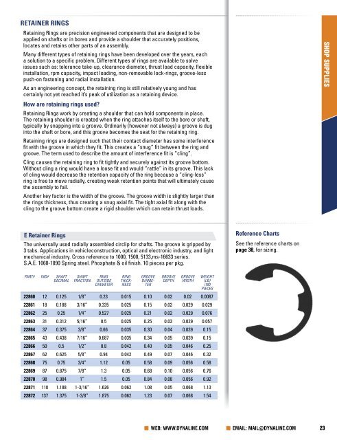
E Retainer Rings<br />
The universally used radially assembled circlip for shafts. The groove is gripped by<br />
3 tabs. Applications in vehicleconstruction, optical and electronic industry, and light<br />
mechanical industry. Cross reference to 1000, 1500, 5133,ms-16633 series.<br />
S.A.E. 1060-1090 Spring steel. Phosphate & oil finish. 10 pieces per pkg.<br />
Reference Charts<br />
See the reference charts on<br />
page 38, for sizing.<br />
PART# IND# SHAFT<br />
DECIMAL<br />
SHAFT<br />
FRACTION<br />
RING<br />
OUTSIDE<br />
DIAMETER<br />
RING<br />
THICK-<br />
NESS<br />
GROOVE<br />
DIAME-<br />
TER<br />
GROOVE<br />
DEPTH<br />
GROOVE<br />
WIDTH<br />
WEIGHT<br />
(LB)<br />
/100<br />
PIECES<br />
22860 12 0.125 1/8” 0.23 0.015 0.10 0.02 0.02 0.0087<br />
22861 18 0.188 3/16” 0.335 0.025 0.15 0.02 0.029 0.029<br />
22862 25 0.25 1/4” 0.527 0.025 0.21 0.02 0.029 0.076<br />
22863 31 0.312 5/16” 0.5 0.025 0.25 0.03 0.029 0.057<br />
22864 37 0.375 3/8” 0.66 0.035 0.30 0.04 0.039 0.15<br />
22865 43 0.438 7/16” 0.687 0.035 0.34 0.05 0.039 0.15<br />
22866 50 0.5 1/2” 0.8 0.042 0.40 0.05 0.046 0.25<br />
22867 62 0.625 5/8” 0.94 0.042 0.49 0.07 0.046 0.32<br />
22868 75 0.75 3/4” 1.12 0.05 0.58 0.09 0.056 0.58<br />
22869 87 0.875 7/8” 1.3 0.05 0.68 0.10 0.056 0.76<br />
22870 98 0.984 1” 1.5 0.05 0.84 0.08 0.056 0.92<br />
22871 118 1.188 1-3/16” 1.626 0.062 1.08 0.05 0.068 1.13<br />
22872 137 1.375 1-3/8” 1.875 0.062 1.23 0.07 0.068 1.54<br />
WEB: WWW.DYNALINE.COM EMAIL: MAIL@DYNALINE.COM 23


