

Sony CDX-GT540UI - CDX-GT540UI Guide d'installation
Sony CDX-GT540UI - CDX-GT540UI Guide d'installation
Sony CDX-GT540UI - CDX-GT540UI Guide d'installation

You also want an ePaper? Increase the reach of your titles
YUMPU automatically turns print PDFs into web optimized ePapers that Google loves.
4-152-751-31(1)<br />
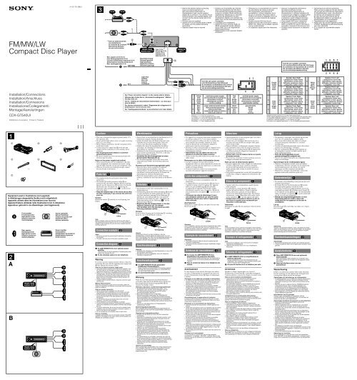
* 1 Note for the antenna (aerial) connecting<br />
If your car antenna (aerial) is an<br />
ISO (International Organization for<br />
Standardization) type, use the supplied<br />
adaptor to connect it. First connect the car<br />
antenna (aerial) to the supplied adaptor, then<br />
connect it to the antenna (aerial) jack of the<br />
master unit.<br />
* 2 RCA pin cord (not supplied)<br />
* 3 AUDIO OUT can be switched SUB or REAR.<br />
For details, see the supplied Operating<br />
Instructions.<br />
* 4 Separate adaptor may be required.<br />
* 2<br />
* 1 Hinweis zum Anschließen der Antenne<br />
Wenn Ihre Autoantenne der ISO-Norm<br />
(Internationale Normungsgemeinschaft)<br />
entspricht, schließen Sie sie mithilfe des<br />
mitgelieferten Adapters an. Verbinden<br />
Sie zuerst die Autoantenne mit dem<br />
mitgelieferten Adapter und verbinden Sie<br />
diesen dann mit der Antennenbuchse des<br />
Hauptgeräts.<br />
* 2 Cinchkabel (nicht mitgeliefert)<br />
* 3 AUDIO OUT kann zwischen SUB und<br />
REAR umgeschaltet werden. Näheres<br />
hierzu finden Sie in der mitgelieferten<br />
Bedienungsanleitung.<br />
* 4 Möglicherweise ist ein separater Adapter<br />
erforderlich.<br />
* 1 Remarque sur le raccordement de l’antenne<br />
Si votre antenne de voiture est de type<br />
ISO (Organisation internationale de<br />
normalisation), utilisez l’adaptateur fourni<br />
pour la raccorder. Raccordez d’abord<br />
l’antenne de voiture à l’adaptateur fourni et,<br />
ensuite, à la prise d’antenne de l’appareil<br />
principal.<br />
* 2 Cordon à broche RCA (non fourni)<br />
* 3 AUDIO OUT peut être commuté sur SUB ou<br />
REAR. Pour obtenir plus de détails, reportezvous<br />
au mode d’emploi.<br />
* 4 Un adaptateur séparé peut être nécessaire.<br />
* 1 Nota per il collegamento dell’antenna<br />
Se l’antenna dell’auto è di tipo<br />
ISO (International Organization for<br />
Standardization), utilizzare l’adattatore <br />
in dotazione per collegarla. Collegare prima<br />
l’antenna della macchina all’adattatore<br />
in dotazione, quindi collegarla alla presa<br />
dell’antenna dell’apparecchio principale.<br />
* 2 Cavo a piedini RCA (non in dotazione)<br />
* 3 AUDIO OUT può essere impostato su<br />
SUB o su REAR. Per ulteriori informazioni,<br />
consultare il manuale di istruzioni per l’uso.<br />
* 4 Potrebbe essere necessario un adattatore<br />
separato.<br />
* 1 Opmerking bij de antenne-aansluiting<br />
Indien uw auto is uitgerust met een antenne<br />
van het type ISO (International Organization<br />
for Standardization), moet u die aansluiten<br />
met behulp van de bijgeleverde adapter<br />
. Sluit eerst de auto-antenne aan op<br />
de bijgeleverde adapter en vervolgens de<br />
antennestekker op het hoofdtoestel.<br />
* 2 Tulpstekkersnoer (niet bijgeleverd)<br />
* 3 AUDIO OUT kan worden ingesteld op SUB<br />
of REAR. Raadpleeg de gebruiksaanwijzing<br />
voor meer informatie.<br />
* 4 Er is mogelijk een afzonderlijke adapter<br />
vereist.<br />
FM/MW/LW<br />
Compact Disc Player<br />
* 1 from car antenna (aerial)<br />
von Autoantenne<br />
de l’antenne de la voiture<br />
dall’antenna dell’auto<br />
van een auto-antenne<br />
<br />
Max. supply current 0.3 A<br />
max. Versorgungsstrom 0,3 A<br />
Courant d’alimentation maximum 0,3 A<br />
Alimentazione massima fornita 0,3 A<br />
Max. voedingsstroom 0,3 A<br />
AMP REM<br />
REAR / SUB<br />
REAR/SUB<br />
AUDIO OUT<br />
Blue/white striped<br />
Blauweiß gestreift<br />
Rayé bleu/blanc<br />
Rigato blu e bianco<br />
Blauw/wit gestreept<br />
L<br />
R<br />
Fuse (10 A)<br />
Sicherung (10 A)<br />
Fusible (10 A)<br />
Fusibile (10 A)<br />
Zekering (10 A)<br />
<br />
REMOTE<br />
IN* 4<br />
from the car’s speaker connector<br />
vom Lautsprecheranschluss des Fahrzeugs<br />
du connecteur de haut-parleur de la voiture<br />
dal connettore dei diffusori dell’auto<br />
van de autoluidsprekeraansluiting<br />
1 3 5 7<br />
2 4 6 8<br />
Installation/Connections<br />
Installation/Anschluss<br />
Installation/Connexions<br />
Installazione/Collegamenti<br />
Montage/Aansluitingen<br />
<strong>CDX</strong>-<strong>GT540UI</strong><br />
©2009 <strong>Sony</strong> Corporation Printed in Thailand<br />
ATT<br />
Light blue<br />
Hellblau<br />
Bleu ciel<br />
Azzurro<br />
Lichtblauw<br />
See “Power connection diagram” on the reverse side for details.<br />
Näheres dazu finden Sie im „Stromanschlussdiagramm“. Blättern<br />
Sie dazu bitte um.<br />
Voir le « Schéma de raccordement d’alimentation » au verso pour<br />
plus de détails.<br />
Per ulteriori informazioni, vedere “Diagramma dei collegamenti di<br />
alimentazione” che si trova sul retro.<br />
Zie "Voedingsaansluitschema" op de achterkant voor meer details.<br />
AUDIO OUT* 3 5 7<br />
4<br />
5<br />
Yellow<br />
Gelb<br />
Jaune<br />
Giallo<br />
Geel<br />
Blue<br />
Blau<br />
Bleu<br />
Blu<br />
Blauw<br />
from the car’s power connector<br />
vom Stromanschluss des Fahrzeugs<br />
du connecteur d’alimentation de la voiture<br />
dal connettore di alimentazione dell’auto<br />
van de autovoedingsaansluiting<br />
continuous power supply<br />
permanente Stromversorgung<br />
alimentation continue<br />
alimentazione continua<br />
continu voeding<br />
power antenna (aerial) control<br />
Motorantennensteuerung<br />
antenne électrique<br />
comando dell’antenna elettrica<br />
elektrische antenne<br />
Positions 1, 2, 3, and 6 do not have pins.<br />
An Position 1, 2, 3 und 6 befinden sich keine Stifte.<br />
Les positions 1, 2, 3 et 6 ne comportent pas de broches.<br />
Le posizioni 1, 2, 3 e 6 non hanno piedini.<br />
De posities 1, 2, 3 en 6 hebben geen pins.<br />
7<br />
8<br />
Red<br />
Rot<br />
Rouge<br />
Rosso<br />
Rood<br />
Black<br />
Schwarz<br />
Noir<br />
Nero<br />
Zwart<br />
4 8<br />
switched power supply<br />
geschaltete Stromversorgung<br />
alimentation commutée<br />
alimentazione commutata<br />
geschakelde voeding<br />
ground (earth)<br />
Masse<br />
masse<br />
terra<br />
aarding<br />
1<br />
2<br />
Purple<br />
Violett<br />
Violet<br />
Viola<br />
Paars<br />
+<br />
–<br />
3<br />
Gray<br />
Grau<br />
Gris<br />
Grigio<br />
Grijs<br />
+<br />
4 –<br />
Speaker, Rear, Right<br />
Lautsprecher hinten rechts<br />
Haut-parleur, arrière, droit<br />
Diffusore, posteriore, destro<br />
Luidspreker, achter, rechts<br />
Speaker, Rear, Right<br />
Lautsprecher hinten rechts<br />
Haut-parleur, arrière, droit<br />
Diffusore, posteriore, destro<br />
Luidspreker, achter, rechts<br />
Speaker, Front, Right<br />
Lautsprecher vorne rechts<br />
Haut-parleur, avant, droit<br />
Diffusore, anteriore, destro<br />
Luidspreker, voor, rechts<br />
Speaker, Front, Right<br />
Lautsprecher vorne rechts<br />
Haut-parleur, avant, droit<br />
Diffusore, anteriore, destro<br />
Luidspreker, voor, rechts<br />
Negative polarity positions 2, 4, 6, and 8 have striped leads.<br />
An den negativ gepolten Positionen 2, 4, 6 und 8 befinden sich gestreifte Adern.<br />
Les positions de polarité négative 2, 4, 6 et 8 sont dotées de cordons rayés.<br />
Le posizioni a polarità negativa 2, 4, 6 e 8 hanno cavi rigati.<br />
De posities voor negatieve polariteit (2, 4, 6 en 8) hebben gestreepte kabels.<br />
5<br />
6<br />
White<br />
Weiß<br />
Blanc<br />
Bianco<br />
Wit<br />
+<br />
–<br />
7<br />
Green<br />
Grün<br />
Vert<br />
Verde<br />
Groen<br />
+<br />
8 –<br />
Speaker, Front, Left<br />
Lautsprecher vorne links<br />
Haut-parleur, avant, gauche<br />
Diffusore, anteriore, sinistro<br />
Luidspreker, voor, links<br />
Speaker, Front, Left<br />
Lautsprecher vorne links<br />
Haut-parleur, avant, gauche<br />
Diffusore, anteriore, sinistro<br />
Luidspreker, voor, links<br />
Speaker, Rear, Left<br />
Lautsprecher hinten links<br />
Haut-parleur, arrière, gauche<br />
Diffusore, posteriore, sinistro<br />
Luidspreker, achter, links<br />
Speaker, Rear, Left<br />
Lautsprecher hinten links<br />
Haut-parleur, arrière, gauche<br />
Diffusore, posteriore, sinistro<br />
Luidspreker, achter, links<br />
Cautions<br />
Warnhinweise<br />
Précautions<br />
Attenzione<br />
Let op<br />
<br />
<br />
<br />
× 2<br />
Equipment used in illustrations (not supplied)<br />
In Abbildungen dargestellte Geräte (nicht mitgeliefert)<br />
Appareils utilisés dans les illustrations (non fournis)<br />
Apparecchiatura utilizzata nelle illustrazioni (non in dotazione)<br />
Apparatuur gebruikt in de afbeeldingen (niet bijgeleverd)<br />
A<br />
B<br />
Front speaker<br />
Frontlautsprecher<br />
Haut-parleur avant<br />
Diffusore anteriore<br />
Voorluidspreker<br />
Rear speaker<br />
Hecklautsprecher<br />
Haut-parleur arrière<br />
Diffusore posteriore<br />
Achterluidspreker<br />
REAR / SUB<br />
AUDIO OUT<br />
REAR / SUB<br />
AUDIO OUT<br />
<br />
<br />
<br />
<br />
Active subwoofer<br />
Aktiver Tiefsttöner<br />
Caisson de graves actif<br />
Subwoofer attivo<br />
Actieve subwoofer<br />
Power amplifier<br />
Endverstärker<br />
Amplificateur de puissance<br />
Amplificatore di potenza<br />
Eindversterker<br />
• This unit is designed for negative ground (earth) 12 V<br />
DC operation only.<br />
• Do not get the leads under a screw, or caught in moving<br />
parts (e.g. seat railing).<br />
• Before making connections, turn the car ignition off to<br />
avoid short circuits.<br />
• Connect the power supply lead to the unit and<br />
speakers before connecting it to the auxiliary power<br />
connector.<br />
• Run all ground (earth) leads to a common<br />
ground (earth) point.<br />
• Be sure to insulate any loose unconnected leads with<br />
electrical tape for safety.<br />
Notes on the power supply lead (yellow)<br />
• When connecting this unit in combination with other<br />
stereo components, the connected car circuit’s rating<br />
must be higher than the sum of each component’s fuse.<br />
• When no car circuits are rated high enough, connect<br />
the unit directly to the battery.<br />
Parts list<br />
• The numbers in the list are keyed to those in the<br />
instructions.<br />
• The bracket and the protection collar are<br />
attached to the unit before shipping. Before mounting<br />
the unit, use the release keys to remove the bracket<br />
from the unit. For details, see “Removing the<br />
protection collar and the bracket ()” on the reverse<br />
side of the sheet.<br />
• Keep the release keys for future use as they<br />
are also necessary if you remove the unit from<br />
your car.<br />
Caution<br />
Handle the bracket carefully to avoid injuring your<br />
fingers.<br />
<br />
Catch<br />
Note<br />
Before installing, make sure that the catches on both sides of<br />
the bracket are bent inwards 2 mm ( 3 /32 in). If the catches are<br />
straight or bent outwards, the unit will not be installed securely<br />
and may spring out.<br />
Connection example<br />
Notes<br />
• Be sure to connect the ground (earth) lead before connecting<br />
the amplifier.<br />
• The alarm will only sound if the built-in amplifier is used.<br />
Connection diagram<br />
To AMP REMOTE IN of an optional power<br />
amplifier<br />
This connection is only for amplifiers. Connecting any other<br />
system may damage the unit.<br />
To the interface cable of a car telephone<br />
Warning<br />
If you have a power antenna (aerial) without a relay box,<br />
connecting this unit with the supplied power supply lead<br />
may damage the antenna (aerial).<br />
Notes on the control and power supply leads<br />
• The power antenna (aerial) control lead (blue) supplies +12 V<br />
DC when you turn on the tuner, or when you activate the AF<br />
(Alternative Frequency) or TA (Traffic Announcement) function.<br />
• When your car has built-in FM/MW/LW antenna (aerial) in the<br />
rear/side glass, connect the power antenna (aerial) control<br />
lead (blue) or the accessory power supply lead (red) to the<br />
power terminal of the existing antenna (aerial) booster. For<br />
details, consult your dealer.<br />
• A power antenna (aerial) without a relay box cannot be used<br />
with this unit.<br />
Memory hold connection<br />
When the yellow power supply lead is connected, power will<br />
always be supplied to the memory circuit even when the ignition<br />
switch is turned off.<br />
Notes on speaker connection<br />
• Before connecting the speakers, turn the unit off.<br />
• Use speakers with an impedance of 4 to 8 ohms, and with<br />
adequate power handling capacities to avoid its damage.<br />
• Do not connect the speaker terminals to the car chassis, or<br />
connect the terminals of the right speakers with those of the<br />
left speaker.<br />
• Do not connect the ground (earth) lead of this unit to the<br />
negative (–) terminal of the speaker.<br />
• Do not attempt to connect the speakers in parallel.<br />
• Connect only passive speakers. Connecting active speakers<br />
(with built-in amplifiers) to the speaker terminals may damage<br />
the unit.<br />
• To avoid a malfunction, do not use the built-in speaker leads<br />
installed in your car if the unit shares a common negative (–)<br />
lead for the right and left speakers.<br />
• Do not connect the unit’s speaker leads to each other.<br />
Note on connection<br />
If speaker and amplifier are not connected correctly, “FAILURE”<br />
appears in the display. In this case, make sure the speaker and<br />
amplifier are connected correctly.<br />
• Dieses Gerät ist ausschließlich für den Betrieb bei 12 V<br />
Gleichstrom (negative Erdung) bestimmt.<br />
• Achten Sie darauf, dass die Kabel nicht unter einer<br />
Schraube oder zwischen beweglichen Teilen wie<br />
z. B. in einer Sitzschiene eingeklemmt werden.<br />
• Schalten Sie, bevor Sie irgendwelche Anschlüsse<br />
vornehmen, die Zündung des Fahrzeugs aus, um<br />
Kurzschlüsse zu vermeiden.<br />
• Verbinden Sie das Stromversorgungskabel mit dem<br />
Gerät und den Lautsprechern, bevor Sie es mit dem<br />
Hilfsstromanschluss verbinden.<br />
• Schließen Sie alle Erdungskabel an einen<br />
gemeinsamen Massepunkt an.<br />
• Aus Sicherheitsgründen müssen alle losen, nicht<br />
angeschlossenen Drähte mit Isolierband abisoliert<br />
werden.<br />
Hinweise zum Stromversorgungskabel (gelb)<br />
• Wenn Sie dieses Gerät zusammen mit anderen<br />
Stereokomponenten anschließen, muss der<br />
Autostromkreis, an den die Geräte angeschlossen sind,<br />
eine höhere Leistung aufweisen als die Summe der<br />
Sicherungen der einzelnen Komponenten.<br />
• Wenn kein Autostromkreis eine so hohe Leistung<br />
aufweist, schließen Sie das Gerät direkt an die Batterie<br />
an.<br />
Teileliste<br />
• Die Nummern in der Liste sind dieselben wie im<br />
Erläuterungstext.<br />
• Die Halterung und die Schutzumrandung werden<br />
vor dem Ausliefern am Gerät angebracht. Bevor Sie<br />
das Gerät montieren, nehmen Sie die Halterung <br />
mithilfe der Löseschlüssel bitte vom Gerät ab.<br />
Einzelheiten dazu finden Sie unter „Abnehmen der<br />
Schutzumrandung und der Halterung ()“ auf der<br />
Rückseite dieses Blattes.<br />
• Bewahren Sie die Löseschlüssel für den<br />
späteren Gebrauch auf. Sie werden<br />
z. B. benötigt, wenn Sie das Gerät aus dem<br />
Fahrzeug ausbauen wollen.<br />
Vorsicht<br />
Seien Sie beim Umgang mit der Halterung vorsichtig,<br />
damit Sie sich nicht die Hände verletzen.<br />
<br />
Verriegelung<br />
Hinweis<br />
Vergewissern Sie sich vor dem Installieren, dass die<br />
Verriegelungen an beiden Seiten der Halterung um 2 mm<br />
nach innen gebogen sind. Wenn die Verriegelungen gerade oder<br />
nach außen gebogen sind, lässt sich das Gerät nicht sicher<br />
installieren und kann herausspringen.<br />
Anschlussbeispiel<br />
Hinweise<br />
• Schließen Sie unbedingt zuerst das Massekabel an, bevor Sie<br />
den Verstärker anschließen.<br />
• Der Warnton wird nur ausgegeben, wenn der integrierte<br />
Verstärker verwendet wird.<br />
Anschlussdiagramm<br />
An AMP REMOTE IN des gesondert<br />
erhältlichen Endverstärkers<br />
Dieser Anschluss ist ausschließlich für Verstärker gedacht.<br />
Schließen Sie nichts anderes daran an. Andernfalls kann<br />
das Gerät beschädigt werden.<br />
An Schnittstellenkabel eines Autotelefons<br />
Warnung<br />
Wenn Sie eine Motorantenne ohne Relaiskästchen<br />
verwenden, kann durch Anschließen dieses Geräts mit<br />
dem mitgelieferten Stromversorgungskabel die<br />
Antenne beschädigt werden.<br />
Hinweise zu den Steuer- und Stromversorgungsleitungen<br />
• Die Motorantennen-Steuerleitung (blau) liefert +12 V<br />
Gleichstrom, wenn Sie den Tuner einschalten oder die<br />
AF- (Alternativfrequenzsuche) oder die TA-Funktion<br />
(Verkehrsdurchsagen) aktivieren.<br />
• Wenn das Fahrzeug mit einer in der Heck-/<br />
Seitenfensterscheibe integrierten FM (UKW)/MW/LW-<br />
Antenne ausgestattet ist, schließen Sie die Motorantennen-<br />
Steuerleitung (blau) oder die Zubehörstromversorgungsleitung<br />
(rot) an den Stromversorgungsanschluss des vorhandenen<br />
Antennenverstärkers an. Näheres dazu erfahren Sie bei Ihrem<br />
Händler.<br />
• Es kann nur eine Motorantenne mit Relaiskästchen<br />
angeschlossen werden.<br />
Stromversorgung des Speichers<br />
Wenn die gelbe Stromversorgungsleitung angeschlossen ist,<br />
wird der Speicher stets (auch bei ausgeschalteter Zündung) mit<br />
Strom versorgt.<br />
Hinweise zum Lautsprecheranschluss<br />
• Schalten Sie das Gerät aus, bevor Sie die Lautsprecher<br />
anschließen.<br />
• Verwenden Sie Lautsprecher mit einer Impedanz zwischen 4 und<br />
8 Ohm und ausreichender Belastbarkeit. Ansonsten können die<br />
Lautsprecher beschädigt werden.<br />
• Verbinden Sie die Lautsprecheranschlüsse nicht mit dem<br />
Wagenchassis und verbinden Sie auch nicht die Anschlüsse<br />
des rechten mit denen des linken Lautsprechers.<br />
• Verbinden Sie die Masseleitung dieses Geräts nicht mit dem<br />
negativen (–) Lautsprecheranschluss.<br />
• Versuchen Sie nicht, Lautsprecher parallel anzuschließen.<br />
• An die Lautsprecheranschlüsse dieses Geräts dürfen nur<br />
Passivlautsprecher angeschlossen werden. Schließen Sie<br />
keine Aktivlautsprecher (Lautsprecher mit eingebauten<br />
Verstärkern) an, da das Gerät sonst beschädigt werden<br />
könnte.<br />
• Um Fehlfunktionen zu vermeiden, verwenden Sie nicht die<br />
im Fahrzeug installierten, integrierten Lautsprecherleitungen,<br />
wenn am Ende eine gemeinsame negative (–) Leitung für den<br />
rechten und den linken Lautsprecher verwendet wird.<br />
• Verbinden Sie nicht die Lautsprecherkabel des Geräts<br />
miteinander.<br />
Hinweis zum Anschließen<br />
Wenn Lautsprecher und Verstärker nicht richtig angeschlossen<br />
sind, erscheint „FAILURE“ im Display. Vergewissern Sie sich<br />
in diesem Fall, dass Lautsprecher und Verstärker richtig<br />
angeschlossen sind.<br />
• Cet appareil est conçu pour fonctionner uniquement sur<br />
un courant continu de 12 V avec masse négative.<br />
• Evitez de coincer les câbles sous des vis ou dans des<br />
pièces mobiles (par exemple, armature de siège).<br />
• Avant d’effectuer des raccordements, éteignez le<br />
moteur pour éviter les courts-circuits.<br />
• Branchez le câble d’alimention sur l’appareil et les<br />
haut-parleurs avant de le brancher sur le connecteur<br />
d’alimentation auxiliaire.<br />
• Rassemblez tous les câbles de mise à la<br />
masse en un point de masse commun.<br />
• Veillez à isoler tout câble lâche non raccordé avec du<br />
ruban isolant.<br />
Remarques sur le câble d’alimentation (jaune)<br />
• Lorsque cet appareil est raccordé à d’autres<br />
équipements stéréo, la valeur nominale des circuits du<br />
véhicule raccordés doit être supérieure à la somme des<br />
fusibles de chaque élément.<br />
• Si aucun circuit de la voiture n’est assez puissant,<br />
raccordez directement l’appareil à la batterie.<br />
Liste des composants<br />
• Les numéros de la liste correspondent à ceux des<br />
instructions.<br />
• Le support et le tour de protection sont fixés à<br />
l’appareil en usine. Avant le montage de l’appareil,<br />
utilisez les clés de déblocage pour détacher<br />
le support de l’appareil. Pour de plus amples<br />
informations, reportez-vous à la section « Retrait du<br />
tour de protection et du support () » au verso de la<br />
feuille.<br />
• Conservez les clés de déblocage pour<br />
une utilisation ultérieure car vous en aurez<br />
également besoin pour retirer l’appareil de<br />
votre véhicule.<br />
Avertissement<br />
Manipulez le support avec soin pour éviter de vous<br />
blesser aux doigts.<br />
<br />
Loquet<br />
Remarque<br />
Avant l’installation, assurez-vous que les loquets des deux côtés<br />
du support sont bien pliés de 2 mm vers l’intérieur. Si les<br />
loquets sont droits ou pliés vers l’extérieur, l’appareil ne peut pas<br />
être fixé solidement et peut se détacher.<br />
Exemple de raccordement<br />
Remarques<br />
• Raccordez d’abord le câble de mise à la masse avant de<br />
connecter l’amplificateur.<br />
• L’alarme est émise uniquement lorsque l’amplificateur intégré<br />
est utilisé.<br />
Schémas de raccordement<br />
Au niveau du AMP REMOTE IN d’un<br />
amplificateur de puissance facultatif<br />
Ce raccordement existe seulement pour les amplificateurs.<br />
Le raccordement à tout autre système peut endommager<br />
l’appareil.<br />
Vers le cordon de liaison d’un téléphone de<br />
voiture<br />
Avertissement<br />
Si vous disposez d’une antenne électrique sans boîtier<br />
de relais, le branchement de cet appareil au moyen du<br />
cordon d’alimentation fourni risque d’endommager<br />
l’antenne.<br />
Remarques sur les câbles de commande et d’alimentation<br />
• Le câble de commande d’antenne électrique (bleu) fournit du<br />
courant continu de +12 V lorsque vous mettez le tuner sous<br />
tension ou lorsque vous activez la fonction AF (fréquence<br />
alternative) ou TA (informations de circulation).<br />
• Lorsque votre voiture est équipée d’une antenne FM/MW<br />
(GO)/LW (PO) intégrée dans la vitre arrière/latérale, raccordez<br />
le câble de commande d’antenne électrique (bleu) ou le<br />
câble d’alimentation des accessoires (rouge) au bornier<br />
de l’amplificateur d’antenne existant. Pour plus de détails,<br />
consultez votre revendeur.<br />
• Une antenne électrique sans boîtier de relais ne peut pas être<br />
utilisée avec cet appareil.<br />
Raccordement pour la conservation de la mémoire<br />
Lorsque le câble d’alimentation jaune est raccordé, le circuit<br />
de la mémoire est alimenté en permanence même si la clé de<br />
contact est en position d’arrêt.<br />
Remarques sur le raccordement des haut-parleurs<br />
• Avant de raccorder les haut-parleurs, mettre l’appareil hors<br />
tension.<br />
• Utiliser des haut-parleurs ayant une impédance de 4 à 8 ohms<br />
et une capacité adéquate sous peine de les endommager.<br />
• Ne pas raccorder les bornes du système de haut-parleurs au<br />
châssis de la voiture et ne pas connecter les bornes du hautparleur<br />
droit à celles du haut-parleur gauche.<br />
• Ne pas raccorder le câble de mise à la masse de cet appareil<br />
à la borne négative (–) du haut-parleur.<br />
• Ne pas tenter de raccorder les haut-parleurs en parallèle.<br />
• Connecter uniquement des haut-parleurs passifs. La<br />
connexion de haut-parleurs actifs (avec des amplificateurs<br />
intégrés) aux bornes des haut-parleurs pourrait endommager<br />
l’appareil.<br />
• Pour éviter tout problème de fonctionnement, n’utilisez pas les<br />
câbles des haut-parleurs intégrés installés dans votre voiture<br />
si l’appareil dispose d’un câble négatif commun (–) pour les<br />
haut-parleurs droit et gauche.<br />
• Ne raccordez pas entre eux les cordons des haut-parleurs de<br />
l’appareil.<br />
Remarque sur le raccordement<br />
Si les enceintes et l’amplificateur ne sont pas raccordés<br />
correctement, le message « FAILURE » s’affiche. Dans ce cas,<br />
assurez-vous que les enceintes et l’amplificateur sont raccordés<br />
correctement.<br />
• Questo apparecchio è stato progettato per l’uso solo a<br />
12 V CC con massa negativa.<br />
• Evitare che i cavi rimangano bloccati da una vite o<br />
incastrati nelle parti mobili (ad esempio nelle guide<br />
scorrevoli dei sedili).<br />
• Prima di effettuare i collegamenti, spegnere il motore<br />
dell’automobile onde evitare di causare cortocircuiti.<br />
• Collegare il cavo di alimentazione all’apparecchio<br />
e ai diffusori prima di collegarlo al connettore di<br />
alimentazione ausiliaria.<br />
• Portare tutti i cavi di messa a terra a un punto<br />
di massa comune.<br />
• Per sicurezza, assicurarsi di isolare qualsiasi cavo non<br />
collegato utilizzando del nastro adesivo.<br />
Note sul cavo di alimentazione (giallo)<br />
• Se questo apparecchio viene collegato in combinazione<br />
con altri componenti stereo, la potenza nominale<br />
dei circuiti dell’automobile deve essere superiore a<br />
quella prodotta dalla somma dei fusibili di ciascun<br />
componente.<br />
• Se la potenza nominale dei circuiti dell’automobile non<br />
è sufficiente, collegare l’apparecchio direttamente alla<br />
batteria.<br />
Elenco dei componenti<br />
• I numeri nella lista corrispondono a quelli riportati<br />
nelle istruzioni.<br />
• La staffa e la cornice protettiva vengono<br />
applicati all’unità in fabbrica. Prima di installare<br />
l’unità, utilizzare le chiavette di rilascio per<br />
rimuovere la staffa dall’apparecchio. Per ulteriori<br />
informazioni, vedere “Rimozione della staffa e della<br />
cornice protettiva ()” sul lato opposto del foglio.<br />
• Conservare le chiavette di rilascio per un<br />
uso futuro in quanto sono necessarie per<br />
rimuovere l’unità dall’auto.<br />
Attenzione<br />
Maneggiare la staffa con cautela per evitare di ferirsi<br />
le mani.<br />
<br />
Fermo<br />
Nota<br />
Prima di installare l’unità, accertarsi di ripiegare i fermi presenti<br />
su entrambi i lati della staffa verso l’interno di 2 mm. Se i fermi<br />
sono diritti o ripiegati verso l’esterno, l’apparecchio non verrà<br />
installato in modo sicuro e potrebbe fuoriuscire.<br />
Esempio di collegamento<br />
Note<br />
• Assicurarsi di collegare il cavo di terra prima di collegare<br />
l’apparecchio all’amplificatore.<br />
• L’allarme viene emesso solo se è in uso l’amplificatore<br />
incorporato.<br />
Schema di collegamento<br />
A AMP REMOTE IN di un amplificatore di<br />
potenza opzionale<br />
Questo collegamento è riservato esclusivamente agli<br />
amplificatori. Non collegare un tipo di sistema diverso onde<br />
evitare di causare danni all’apparecchio.<br />
Al cavo di interfaccia di un telefono per auto<br />
Avvertenza<br />
Quando si collega l’apparecchio con il cavo di<br />
alimentazione in dotazione , si potrebbe danneggiare<br />
l’antenna elettrica se questa non dispone di scatola a relè.<br />
Note sui cavi di controllo e di alimentazione<br />
• Il cavo (blu) di controllo dell’antenna elettrica fornisce<br />
alimentazione pari a +12 V CC quando si attiva il<br />
sintonizzatore oppure la funzione TA (notiziario sul traffico) o<br />
AF (frequenza alternativa).<br />
• Se l’automobile è dotata di antenna FM/MW/LW incorporata<br />
nel vetro posteriore/laterale, collegare il cavo (blu) di<br />
controllo dell’antenna elettrica o il cavo (rosso) di ingresso<br />
dell’alimentazione accessoria al terminale di alimentazione<br />
del preamplificatore dell’antenna esistente. Per ulteriori<br />
informazioni, consultare il proprio fornitore.<br />
• Non è possibile usare un’antenna elettrica senza scatola a relè<br />
con questo apparecchio.<br />
Collegamento per la conservazione della memoria<br />
Quando il cavo di ingresso alimentazione giallo è collegato,<br />
viene sempre fornita alimentazione al circuito di memoria anche<br />
quando l’interruttore di accensione è spento.<br />
Note sul collegamento dei diffusori<br />
• Prima di collegare i diffusori spegnere l’apparecchio.<br />
• Usare diffusori di impedenza compresa tra 4 e 8 ohm e con<br />
capacità di potenza adeguata, altrimenti i diffusori potrebbero<br />
venire danneggiati.<br />
• Non collegare i terminali del sistema diffusori al telaio dell’auto<br />
e non collegare i terminali del diffusore destro a quelli del<br />
diffusore sinistro.<br />
• Non collegare il cavo di terra di questo apparecchio al<br />
terminale negativo (–) del diffusore.<br />
• Non collegare i diffusori in parallelo.<br />
• Assicurarsi di collegare soltanto diffusori passivi, poiché<br />
il collegamento di diffusori attivi, dotati di amplificatori<br />
incorporati, ai terminali dei diffusori potrebbe danneggiare<br />
l’apparecchio.<br />
• Per evitare problemi di funzionamento, non utilizzare i cavi dei<br />
diffusori incorporati installati nell’automobile se l’apparecchio<br />
condivide un cavo comune negativo (–) per i diffusori destro e<br />
sinistro.<br />
• Non collegare fra loro i cavi dei diffusori dell’apparecchio.<br />
Nota sui collegamenti<br />
Se l’amplificatore e il diffusore non sono collegati correttamente,<br />
“FAILURE” viene visualizzato nel display. In tal caso, accertarsi<br />
che l’amplificatore e il diffusore siano collegati correttamente.<br />
• Dit apparaat is ontworpen voor gebruik op een autoaccu<br />
van 12 V gelijkstroom, negatieve aarde.<br />
• Zorg ervoor dat de draden niet onder een schroef<br />
of tussen bewegende onderdelen (b.v. zetelrail)<br />
terechtkomen.<br />
• Voordat u de aansluitingen maakt, moet u het contact<br />
uitzetten om kortsluiting te vermijden.<br />
• Sluit de voedingskabel aan op het apparaat en<br />
de luidsprekers voordat u de kabel aansluit op de<br />
hulpvoedingsaansluiting.<br />
• Sluit alle aardingskabels op een<br />
gemeenschappelijk aardpunt aan.<br />
• Voorzie niet aangesloten kabels om veiligheidsredenen<br />
altijd van isolatietape.<br />
Opmerkingen bij de voedingskabel (geel)<br />
• Wanneer u dit apparaat aansluit samen met andere<br />
componenten, moet het vermogen van de aangesloten<br />
autostroomkring groter zijn dan de som van de<br />
zekeringen van elke component afzonderlijk.<br />
• Wanneer het vermogen ontoereikend is, moet u het<br />
apparaat rechtstreeks aansluiten op de accu.<br />
Onderdelenlijst<br />
• De nummers in de afbeelding verwijzen naar die in de<br />
montage-aanwijzingen.<br />
• De beugel en de beschermende rand worden<br />
bevestigd op het apparaat voordat dit wordt<br />
verzonden. Voordat u het apparaat plaatst, moet u de<br />
ontgrendelingssleutels gebruiken om de beugel <br />
te verwijderen van het apparaat. Zie "De beschermende<br />
rand en de beugel verwijderen ()" aan de achterzijde<br />
van dit vel voor meer informatie.<br />
• Bewaar de ontgrendelingssleutels voor<br />
toekomstig gebruik omdat u deze ook<br />
nodig hebt om het apparaat uit de auto te<br />
verwijderen.<br />
Let op<br />
Houd de beugel voorzichtig vast zodat u uw vingers<br />
niet verwondt.<br />
<br />
Greep<br />
Opmerking<br />
Voordat u het apparaat installeert, moet u de grepen aan beide<br />
zijden van de beugel 2 mm naar binnen buigen. Als de grepen<br />
recht zijn of naar buiten gebogen, kan het apparaat niet goed<br />
worden bevestigd en kan dit losschieten.<br />
Voorbeeldaansluitingen<br />
Opmerkingen<br />
• Sluit eerst de aarddraad aan voordat u de versterker aansluit.<br />
• U hoort de pieptoon alleen als de ingebouwde versterker wordt<br />
gebruikt.<br />
Aansluitschema<br />
Naar AMP REMOTE IN van een optionele<br />
eindversterker<br />
Deze aansluiting is alleen bedoeld voor versterkers. Door<br />
een ander systeem aan te sluiten kan het apparaat worden<br />
beschadigd.<br />
Naar het interface-snoer van een<br />
autotelefoon<br />
Waarschuwing<br />
Indien u een elektrische antenne hebt zonder relaiskast,<br />
kan het aansluiten van dit apparaat met de bijgeleverde<br />
voedingskabel de antenne beschadigen.<br />
Opmerkingen over de bedienings- en voedingskabels<br />
• De bedieningskabel voor de elektrische antenne (blauw) levert<br />
+12 V gelijkstroom wanneer u de tuner inschakelt of de AF<br />
(Alternative Frequency) of TA (Traffic Announcement) functie<br />
activeert.<br />
• Wanneer uw auto is uitgerust met een FM/MW/LW-antenne<br />
in de achterruit/zijruit, moet u de bedieningskabel voor<br />
de elektrische antenne (blauw) of de hulpvoedingskabel<br />
(rood) aansluiten op de voedingsingang van de bestaande<br />
antenneversterker. Raadpleeg uw dealer voor meer details.<br />
• Met dit apparaat is het niet mogelijk een elektrische antenne<br />
zonder relaiskast te gebruiken.<br />
Instandhouden van het geheugen<br />
Zolang de gele voedingskabel is aangesloten, blijft de<br />
stroomvoorziening van het geheugen intact, ook wanneer het<br />
contact van de auto wordt uitgeschakeld.<br />
Opmerkingen betreffende het aansluiten van de luidsprekers<br />
• Zorg dat het apparaat is uitgeschakeld, alvorens de<br />
luidsprekers aan te sluiten.<br />
• Gebruik luidsprekers met een impedantie van 4 tot 8 Ohm<br />
en let op dat die het vermogen van de versterker kunnen<br />
verwerken. Als u dit niet doet, kunnen de luidsprekers ernstig<br />
beschadigd raken.<br />
• Verbind in geen geval de aansluitingen van de luidsprekers<br />
met het chassis van de auto en sluit de aansluitingen van de<br />
rechter- en linkerluidspreker niet op elkaar aan.<br />
• Verbind de aarddraad van dit apparaat niet met de negatieve<br />
(–) aansluiting van de luidspreker.<br />
• Probeer nooit de luidsprekers parallel aan te sluiten.<br />
• Sluit geen actieve luidsprekers (met ingebouwde versterkers)<br />
aan op de luidsprekeraansluiting van dit apparaat. Dit zal<br />
leiden tot beschadiging van de actieve luidsprekers. Sluit dus<br />
altijd uitsluitend luidsprekers zonder ingebouwde versterker<br />
aan.<br />
• Om defecten te vermijden mag u de bestaande<br />
luidsprekerbedrading in uw auto niet gebruiken wanneer er een<br />
gemeenschappelijke negatieve (–) draad is voor de rechter- en<br />
linkerluidsprekers.<br />
• Verbind de luidsprekerdraden niet met elkaar.<br />
Opmerking over aansluiten<br />
Als de luidspreker en versterker niet correct zijn aangesloten,<br />
wordt "FAILURE" in het display weergegeven. In dit geval moet u<br />
zorgen dat de luidspreker en versterker correct zijn aangesloten.
1 2<br />
<br />
<br />
<br />
Face the hook inwards.<br />
Der Haken muss nach innen<br />
weisen.<br />
Tournez le crochet vers<br />
l’intérieur.<br />
Con il gancetto rivolto verso<br />
l’interno.<br />
Het haakje moet naar binnen<br />
wijzen.<br />
Power connection diagram<br />
Auxiliary power connector may vary depending on the<br />
car. Check your car’s auxiliary power connector diagram<br />
to make sure the connections match correctly. There are<br />
three basic types (illustrated below). You may need to<br />
switch the positions of the red and yellow leads in the car<br />
stereo’s power supply lead.<br />
After matching the connections and switched power<br />
supply leads correctly, connect the unit to the car’s<br />
power supply. If you have any questions and problems<br />
connecting your unit that are not covered in this manual,<br />
please consult the car dealer.<br />
Diagramma dei collegamenti di<br />
alimentazione<br />
Il connettore di alimentazione ausiliaria può variare a<br />
seconda della macchina. Controllare il diagramma del<br />
connettore di alimentazione ausiliaria della macchina<br />
per essere sicuri che i collegamenti corrispondano<br />
correttamente. Vi sono tre tipi di base (illustrazione<br />
sotto). Potrà essere necessario cambiare le posizioni dei<br />
fili rosso e giallo nel cavo di alimentazione dello stereo<br />
della macchina.<br />
Dopo aver fatto corrispondere i collegamenti e<br />
aver commutato i cavi di alimentazione, collegare<br />
l’apparecchio all’alimentazione della macchina. Se si<br />
hanno domande o se sorgono problemi che non sono<br />
stati trattati nel manuale nel collegare l’apparecchio,<br />
contattare l’autoconcessionario.<br />
<br />
Stromanschlussdiagramm<br />
Voedingsaansluitschema<br />
1 2 3<br />
182 mm<br />
<br />
Dashboard<br />
Armaturenbrett<br />
Tableau de bord<br />
Cruscotto<br />
Dashboard<br />
<br />
Fire wall<br />
Motorraumtrennwand<br />
Paroi ignifuge<br />
Parete tagliafiamma<br />
Brandschot<br />
Der Hilfsstromanschluss kann je nach Fahrzeugtyp<br />
unterschiedlich sein. Sehen Sie im Hilfsstromanschlussdiagramm<br />
für Ihr Fahrzeug nach, wie die<br />
Verbindung ordnungsgemäß vorgenommen werden muss.<br />
Es gibt, wie unten abgebildet, drei grundlegende Typen.<br />
Sie müssen möglicherweise die rote und gelbe Leitung<br />
des Stromversorgungskabels der Autostereoanlage<br />
vertauschen.<br />
Stellen Sie die Anschlüsse her, schließen Sie die<br />
geschalteten Stromversorgungsleitungen richtig an und<br />
verbinden Sie dann das Gerät mit der Stromversorgung<br />
Ihres Fahrzeugs. Wenn beim Anschließen des<br />
Geräts Fragen oder Probleme auftreten, die in dieser<br />
Bedienungsanleitung nicht erläutert werden, wenden Sie<br />
sich bitte an den Autohändler.<br />
De hulpvoedingsaansluiting kan verschillen afhankelijk<br />
van de auto. Controleer het hulpvoedingsaansluitschema<br />
dat bij dit apparaat wordt geleverd om te zien of de<br />
aansluitingen kloppen. Er zijn drie basistypes (zie<br />
afbeelding hieronder). Het is mogelijk dat u de posities<br />
van de rode en gele kabels in de voedingskabel van het<br />
car audiosysteem moet omwisselen.<br />
Als de aansluitingen en geschakelde voedingskabels<br />
kloppen, sluit u het apparaat aan op de voeding van de<br />
auto. Indien u nog vragen of problemen hebt in verband<br />
met het aansluiten van het apparaat die niet in deze<br />
handleiding vermeld staan, raadpleeg dan de autodealer.<br />
<br />
<br />
53 mm<br />
Claws<br />
Klammern<br />
Griffes<br />
Morsetti<br />
Klemhaken<br />
<br />
Schéma de raccordement<br />
d’alimentation<br />
Le connecteur d’alimentation auxiliaire peut varier<br />
suivant le type de voiture. Vérifiez le schéma du<br />
connecteur d’alimentation auxiliaire de votre voiture<br />
pour vous assurer que les connexions correspondent. Il<br />
en existe trois types de base (illustrés ci-dessous). Il se<br />
peut que vous deviez commuter la position des fils rouge<br />
et jaune du câble d’alimentation de l’autoradio.<br />
Après avoir établi les connexions et commuté<br />
correctement les câbles d’alimentation, raccordez<br />
l’appareil à l’alimentation de la voiture. Si vous avez<br />
des questions ou des difficultés à propos de cet appareil<br />
qui ne sont pas abordées dans le présent mode d’emploi,<br />
consultez votre concessionnaire automobile.<br />
A<br />
B<br />
(SOURCE/OFF)<br />
Auxiliary power connector<br />
Hilfsstromanschluss<br />
Connecteur d’alimentation auxiliaire<br />
Connettore di alimentazione ausiliaria<br />
Hulpvoedingsaansluiting<br />
Precautions<br />
Sicherheitshinweise<br />
Précautions<br />
Precauzioni<br />
Voorzorgsmaatregelen<br />
Red<br />
Rot<br />
Rouge<br />
Rosso<br />
Rood<br />
Red<br />
Rot<br />
Rouge<br />
Rosso<br />
Rood<br />
• Choose the installation location carefully so that the<br />
unit will not interfere with normal driving operations.<br />
• Avoid installing the unit in areas subject to dust, dirt,<br />
excessive vibration, or high temperature, such as in<br />
direct sunlight or near heater ducts.<br />
• Use only the supplied mounting hardware for a safe<br />
and secure installation.<br />
Mounting angle adjustment<br />
Adjust the mounting angle to less than 45°.<br />
Removing the protection collar<br />
and the bracket<br />
Before installing the unit, remove the protection<br />
collar and the bracket from the unit.<br />
1 Remove the protection collar .<br />
Pinch both edges of the protection collar , then<br />
pull it out.<br />
2 Remove the bracket .<br />
Insert both release keys together between<br />
the unit and the bracket until they click.<br />
Pull down the bracket , then pull up the unit<br />
to separate.<br />
Mounting example<br />
Installation in the dashboard<br />
Notes<br />
• Bend these claws outward for a tight fit, if necessary (-2).<br />
• Make sure that the 4 catches on the protection collar are<br />
properly engaged in the slots of the unit (-3).<br />
How to detach and attach the<br />
front panel<br />
Before installing the unit, detach the front panel.<br />
-A To detach<br />
Before detaching the front panel, be sure to press and<br />
hold . Press , and pull it off towards<br />
you.<br />
-B To attach<br />
Engage part of the front panel with part of the unit,<br />
as illustrated, and push the left side into position until it<br />
clicks.<br />
Warning if your car’s ignition<br />
has no ACC position<br />
Be sure to set the Auto Off function. For details, see the<br />
supplied Operating Instructions.<br />
The unit will shut off completely and automatically in<br />
the set time after the unit is turned off, which prevents<br />
battery drain.<br />
If you do not set the Auto Off function, press and hold<br />
until the display disappears each time<br />
you turn the ignition off.<br />
RESET button<br />
When the installation and connections are completed,<br />
be sure to press the RESET button with a ball-point pen,<br />
etc., after detaching the front panel.<br />
• Wählen Sie den Einbauort sorgfältig so aus, dass das<br />
Gerät beim Fahren nicht hinderlich ist.<br />
• Bauen Sie das Gerät so ein, dass es keinen hohen<br />
Temperaturen (keinem direkten Sonnenlicht, keiner<br />
Warmluft von der Heizung), keinem Staub, keinem<br />
Schmutz und keinen starken Vibrationen ausgesetzt ist.<br />
• Für eine sichere Befestigung verwenden Sie stets die<br />
mitgelieferten Montageteile.<br />
Hinweis zum Montagewinkel<br />
Das Gerät sollte in einem Winkel von weniger als 45°<br />
montiert werden.<br />
Abnehmen der Schutzumrandung<br />
und der Halterung<br />
Nehmen Sie vor dem Installieren des Geräts die<br />
Schutzumrandung und die Halterung vom<br />
Gerät ab.<br />
1 Entfernen Sie die Schutzumrandung .<br />
Fassen Sie die Schutzumrandung mit den<br />
Fingern an den Seitenkanten und ziehen Sie sie<br />
heraus.<br />
2 Entfernen Sie die Halterung .<br />
Führen Sie beide Löseschlüssel zwischen<br />
dem Gerät und der Halterung ein, bis sie<br />
mit einem Klicken einrasten.<br />
Ziehen Sie die Halterung nach unten<br />
und das Gerät nach oben, um die beiden zu<br />
trennen.<br />
Montagebeispiel<br />
Installation im Armaturenbrett<br />
Hinweise<br />
• Falls erforderlich, biegen Sie diese Klammern für einen<br />
sicheren Halt nach außen (-2).<br />
• Achten Sie darauf, die 4 Verriegelungen an der<br />
Schutzumrandung korrekt in die Aussparungen am Gerät<br />
einzusetzen (-3).<br />
Abnehmen und Anbringen der<br />
Frontplatte<br />
Nehmen Sie die Frontplatte vor dem Einbau des<br />
Geräts ab.<br />
-A Abnehmen<br />
Halten Sie vor dem Abnehmen der Frontplatte unbedingt<br />
gedrückt. Drücken Sie und ziehen<br />
Sie sie auf sich zu heraus.<br />
-B Anbringen<br />
Setzen Sie Teil der Frontplatte wie in der Abbildung<br />
dargestellt an Teil des Geräts an und drücken Sie die<br />
linke Seite der Frontplatte an, bis sie mit einem Klicken<br />
einrastet.<br />
Warnhinweis, wenn die Zündung<br />
Ihres Fahrzeugs nicht über eine<br />
Zubehörposition (ACC oder I)<br />
verfügt<br />
Aktivieren Sie unbedingt die Abschaltautomatik.<br />
Näheres dazu finden Sie in der mitgelieferten<br />
Bedienungsanleitung.<br />
Nach dem Ausschalten wird das Gerät dann nach<br />
der voreingestellten Zeit automatisch vollständig<br />
abgeschaltet, so dass der Autobatterie kein Strom mehr<br />
entzogen wird.<br />
Wenn Sie die Abschaltautomatik nicht aktivieren, müssen<br />
Sie jedes Mal, wenn Sie die Zündung ausschalten, die<br />
Taste gedrückt halten, bis die Anzeige<br />
ausgeblendet wird.<br />
Taste RESET<br />
Wenn Sie das Gerät eingebaut und alle Anschlüsse<br />
vorgenommen haben, müssen Sie die Frontplatte<br />
abnehmen und mit einem Kugelschreiber oder einem<br />
anderen spitzen Gegenstand die Taste RESET drücken.<br />
• Choisir soigneusement l’emplacement de l’installation<br />
afin que l’appareil ne gêne pas la conduite normale du<br />
véhicule.<br />
• Eviter d’installer l’appareil dans un endroit exposé à de<br />
la poussière, de la saleté, des vibrations violentes ou à<br />
des températures élevées, comme en plein soleil ou à<br />
proximité d’un conduit de chauffage.<br />
• Pour garantir un montage sûr, n’utiliser que le matériel<br />
fourni.<br />
Réglage de l’angle de montage<br />
Ajuster l’inclinaison à un angle inférieur à 45°.<br />
Retrait du tour de protection et<br />
du support<br />
Avant d’installer l’appareil, retirez le tour de<br />
protection et le support de l’appareil.<br />
1 Enclenchez le tour de protection .<br />
Saisissez les deux bords du tour de protection ,<br />
puis tirez pour extraire l’appareil.<br />
2 Retirez le support .<br />
Insérez les deux clés de déblocage <br />
simultanément entre l’appareil et le support<br />
jusqu’au déclic indiquant qu’elles sont en<br />
place.<br />
Tirez le support vers le bas, puis tirez<br />
l’appareil vers le haut pour les séparer.<br />
Exemple de montage<br />
Installation dans le tableau de bord<br />
Remarques<br />
• Pliez ces griffes vers l’extérieur pour assurer une prise correcte<br />
si nécessaire (-2).<br />
• Assurez-vous que les 4 loquets du tour de protection sont<br />
correctement insérés dans les fentes de l’appareil (-3).<br />
Retrait et fixation de la façade<br />
Avant d’installer l’appareil, retirez la façade.<br />
-A Pour la retirer<br />
Avant de retirer la façade, veillez à appuyer sur la touché<br />
et à la maintenir enfoncée. Appuyez sur<br />
, puis sortez la façade en tirant vers vous.<br />
-B Pour la fixer<br />
Fixez la partie de la façade sur la partie de<br />
l’appareil, comme indiqué sur l’illustration, puis appuyez<br />
sur le côté gauche jusqu’au déclic.<br />
Avertissement au cas où le<br />
contact de votre voiture ne<br />
dispose pas d’une position ACC<br />
Veillez à régler la fonction de mise hors tension<br />
automatique. Pour obtenir davantage d’informations,<br />
reportez-vous au mode d’emploi fourni.<br />
L’appareil s’éteint complètement et automatiquement<br />
après le laps de temps choisi une fois l’appareil mis hors<br />
tension afin d’éviter que la batterie ne se décharge.<br />
Si vous ne réglez pas la fonction de mise hors tension<br />
automatique, appuyez sur la touche <br />
et maintenez-la enfoncée jusqu’à ce que l’affichage<br />
disparaisse à chaque fois que vous coupez le contact.<br />
Touche RESET<br />
Une fois que l’installation et les raccordements sont<br />
terminés, retirez la façade et appuyez sur le bouton<br />
RESET à l’aide d’un stylo à bille ou d’un autre objet<br />
pointu.<br />
• Scegliere con attenzione la posizione per l’installazione<br />
in modo che l’apparecchio non interferisca con le<br />
operazioni di guida del conducente.<br />
• Evitare di installare l’apparecchio dove sia soggetto ad<br />
alte temperature, come alla luce solare diretta o al getto<br />
di aria calda dell’impianto di riscaldamento, o dove<br />
possa essere soggetto a polvere, sporco e vibrazioni<br />
eccessive.<br />
• Usare solo il materiale di montaggio in dotazione per<br />
un’installazione stabile e sicura.<br />
Regolazione dell’angolo di montaggio<br />
Regolare l’angolo di montaggio in modo che sia inferiore<br />
a 45°.<br />
Rimozione della staffa e della<br />
cornice protettiva<br />
Prima di installare l’apparecchio, rimuovere<br />
la cornice protettiva e la staffa <br />
dall’apparecchio.<br />
1 Rimuovere la cornice protettiva .<br />
Afferrare la cornice di protezione dai bordi<br />
laterali, quindi estrarla.<br />
2 Rimuovere la staffa .<br />
Inserire contemporaneamente entrambe le<br />
chiavette di rilascio tra l’apparecchio e la<br />
staffa fino a che non scattano in posizione.<br />
Estrarre la staffa , quindi sollevare<br />
l’apparecchio per rimuoverlo.<br />
Esempio di montaggio<br />
Installazione nel cruscotto<br />
Note<br />
• Piegare verso l’esterno questi morsetti per un’installazione più<br />
sicura, se necessario (-2).<br />
• Assicurarsi che i 4 fermi sulla cornice protettiva siano<br />
correttamente inseriti negli alloggiamenti dell’apparecchio<br />
(-3).<br />
Come rimuovere e reinserire il<br />
pannello anteriore<br />
Prima di installare l’apparecchio rimuovere il<br />
pannello anteriore.<br />
-A Per rimuoverlo<br />
Prima di rimuovere il pannello anteriore, assicurarsi di<br />
tenere premuto . Premere , quindi<br />
tirare verso di sé il pannello anteriore.<br />
-B Per reinserirlo<br />
Applicare la parte del pannello anteriore alla parte<br />
dell’apparecchio come mostrato nell’illustrazione e<br />
premere il lato sinistro fino a sentire uno scatto.<br />
Avvertenza relativa all’installazione<br />
su un’auto sprovvista della<br />
posizione ACC (accessoria) sul<br />
blocchetto di accensione<br />
Accertarsi di impostare la funzione di spegnimento<br />
automatico. Per ulteriori informazioni, fare riferimento<br />
alle istruzioni per l’uso in dotazione.<br />
L’apparecchio si spegne completamente e<br />
automaticamente all’ora impostata dopo che è stato<br />
disattivato, onde evitare che la batteria si scarichi.<br />
Se la funzione di spegnimento automatico non è stata<br />
impostata, ogni volta che il motore viene spento tenere<br />
premuto finché il display non viene<br />
disattivato.<br />
Tasto RESET<br />
Una volta completate le procedure di installazione e i<br />
collegamenti, accertarsi di premere il tasto RESET con<br />
una penna a sfera o un oggetto simile dopo avere rimosso<br />
il pannello anteriore.<br />
• Kies de installatieplaats zorgvuldig zodat het apparaat<br />
de bestuurder niet hindert tijdens het rijden.<br />
• Installeer het apparaat niet op plaatsen waar het<br />
blootgesteld wordt aan hoge temperaturen, b.v. in<br />
direct zonlicht of bij de warme luchtstroom van de<br />
autoverwarming, aan sterke trillingen, of waar het in<br />
contact komt met veel stof of vuil.<br />
• Gebruik voor het veilig en stevig monteren van<br />
het apparaat uitsluitend de bijgeleverde montageonderdelen.<br />
Maximale montagehoek<br />
Installeer het apparaat nooit onder een hoek van meer<br />
dan 45° met het horizontale vlak.<br />
De beschermende rand en de<br />
beugel verwijderen<br />
Voordat u het apparaat gaat installeren, moet<br />
u de beschermende rand en de beugel <br />
verwijderen van het apparaat.<br />
1 Verwijder de beschermende rand .<br />
Druk beide zijden van de beschermende rand <br />
in en trek de rand naar u toe.<br />
2 Verwijder de beugel .<br />
Plaats de ontgrendelingssleutels tussen het<br />
apparaat en de beugel tot deze vastklikken.<br />
Trek de beugel omlaag en trek het apparaat<br />
omhoog om deze van elkaar te scheiden.<br />
Montagevoorbeeld<br />
Montage in het dashboard<br />
Opmerkingen<br />
• Indien nodig kunt u deze klemhaken ombuigen voor een<br />
steviger bevestiging (-2).<br />
• De 4 grepen op de beschermende rand moeten goed in de<br />
sleuven van het apparaat zijn geplaatst (-3).<br />
Het voorpaneel verwijderen en<br />
bevestigen<br />
Verwijder, alvorens met het installeren te<br />
beginnen, het afneembare voorpaneel.<br />
-A Verwijderen<br />
Voordat u het voorpaneel verwijdert, moet u<br />
ingedrukt houden. Druk op<br />
het voorpaneel naar u toe.<br />
en trek<br />
-B Bevestigen<br />
Breng deel van het voorpaneel aan op deel van het<br />
apparaat zoals afgebeeld en druk op de linkerzijde tot<br />
deze vastklikt.<br />
Waarschuwing als het<br />
contactslot van de auto geen<br />
ACC-positie heeft<br />
Zorg ervoor dat u de functie voor automatisch<br />
uitschakelen instelt. Raadpleeg de bijgeleverde<br />
gebruiksaanwijzing voor meer informatie.<br />
Het apparaat wordt na de ingestelde tijd automatisch<br />
volledig uitgeschakeld nadat het apparaat is<br />
uitgeschakeld. Zo wordt voorkomen dat de accu<br />
leegloopt.<br />
Als u de functie voor automatisch uitschakelen niet<br />
instelt, moet u ingedrukt houden tot<br />
het display verdwijnt telkens wanneer u het contact<br />
uitschakelt.<br />
RESET-toets<br />
Als u de installatie en aansluitingen hebt voltooid,<br />
moet u met een puntig voorwerp, zoals de punt van een<br />
balpen, op RESET drukken nadat u het voorpaneel hebt<br />
verwijderd.<br />
4<br />
4<br />
Yellow<br />
Gelb<br />
Jaune<br />
Giallo<br />
Geel<br />
Yellow<br />
Gelb<br />
Jaune<br />
Giallo<br />
Geel<br />
Yellow<br />
Gelb<br />
Jaune<br />
Giallo<br />
Geel<br />
continuous power supply<br />
permanente Stromversorgung<br />
alimentation continue<br />
alimentazione continua<br />
continu voeding<br />
Red<br />
Rot<br />
Rouge<br />
Rosso<br />
Rood<br />
Yellow<br />
Gelb<br />
Jaune<br />
Giallo<br />
Geel<br />
switched power supply<br />
geschaltete Stromversorgung<br />
alimentation commutée<br />
alimentazione commutata<br />
geschakelde voeding<br />
Red<br />
Rot<br />
Rouge<br />
Rosso<br />
Rood<br />
Yellow<br />
Gelb<br />
Jaune<br />
Giallo<br />
Geel<br />
Yellow<br />
Gelb<br />
Jaune<br />
Giallo<br />
Geel<br />
Red<br />
Rot<br />
Rouge<br />
Rosso<br />
Rood<br />
Yellow<br />
Gelb<br />
Jaune<br />
Giallo<br />
Geel<br />
Red<br />
Rot<br />
Rouge<br />
Rosso<br />
Rood<br />
Yellow<br />
Gelb<br />
Jaune<br />
Giallo<br />
Geel<br />
the car without ACC position<br />
Fahrzeug ohne Zubehörposition (ACC oder I)<br />
Véhicule sans position ACC<br />
Auto priva della posizione ACC<br />
Auto zonder ACC-positie<br />
7<br />
7<br />
Red<br />
Rot<br />
Rouge<br />
Rosso<br />
Rood<br />
Red<br />
Rot<br />
Rouge<br />
Rosso<br />
Rood<br />
switched power supply<br />
geschaltete Stromversorgung<br />
alimentation commutée<br />
alimentazione commutata<br />
geschakelde voeding<br />
continuous power supply<br />
permanente Stromversorgung<br />
alimentation continue<br />
alimentazione continua<br />
continu voeding


