1- catalogue sommaire.qxp - Redex-Andantex
1- catalogue sommaire.qxp - Redex-Andantex
1- catalogue sommaire.qxp - Redex-Andantex

Create successful ePaper yourself
Turn your PDF publications into a flip-book with our unique Google optimized e-Paper software.
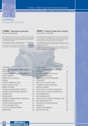
CONTENTS<br />
SOMMAIRE DETAILLE<br />
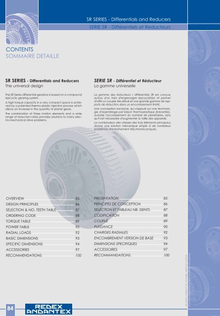
SR SERIES - Differentials and Reducers<br />
The universal design<br />
The SR Series differential gearbox is based on a compound<br />
epicyclic gearing system.<br />
A high torque capacity in a very compact space is achieved<br />
by a patented thermo-plastic injection process which<br />
allows an increase in the quantity of planet gears.<br />
The combination of three motion elements and a wide<br />
range of reduction ratios provides solutions to many electro-mechanical<br />
drive problems.<br />
OVERVIEW 85<br />
DESIGN PRINCIPLES 86<br />
SELECTION & NO. TEETH TABLE 87<br />
ORDERING CODE 88<br />
TORQUE TABLE 89<br />
POWER TABLE 90<br />
RADIAL LOADS 92<br />
BASIC DIMENSIONS 93<br />
SPECIFIC DIMENSIONS 94<br />
ACCESSORIES 97<br />
RECOMMENDATIONS 100<br />
84<br />
www.redex-andantex.com<br />
SR SERIES - Differentials and Reducers<br />
SERIE SR - Différentiels et Reducteurs<br />
SERIE SR - Différentiel et Réducteur<br />
La gamme universelle<br />
La gamme des réducteurs / différentiels SR est conçue<br />
autour d'un train d'engrenages épicycloïdal, et permet<br />
d'offrir un couple très élevé et une grande gamme de rapports<br />
de réduction dans un encombrement limité.<br />
Une conception exclusive, qui s'appuie sur une technologie<br />
d'assemblage par liaison thermoplastique (brevetée),<br />
autorise l'accroissement du nombre de planétaires, sans<br />
qu'il soit nécessaire d'augmenter la taille des appareils.<br />
La combinaison des vitesses des trois éléments principaux<br />
donne une solution mécanique simple à de nombreux<br />
problèmes d'entraînement électromécaniques.<br />
PRESENTATION 85<br />
PRINCIPES DE CONCEPTION 86<br />
SELECTION ET TABLEAU NB DENTS 87<br />
CODIFICATION 88<br />
COUPLE 89<br />
PUISSANCE 90<br />
CHARGES RADIALES 92<br />
ENCOMBREMENT VERSION DE BASE 93<br />
DIMENSIONS SPECIFIQUES 94<br />
ACCESSOIRES 97<br />
RECOMMANDATIONS 100<br />
All data subject to change without notice<br />
Données susceptibles d’être modifiées sans préavis
SR Series Série SR<br />
SR SERIES - Differentials and Reducers<br />
SERIE SR - Différentiels et Reducteurs<br />
KINEMATIC<br />
The REDEX SR series units are based on the epicyclic system<br />
of gearing and have multiple planet trains assembled<br />
by a thermo-plastic injection process (REDEX patent).<br />
The main benefits from this design method are :<br />
Greatly reduced overall dimensions when compared<br />
with traditional gear trains.<br />
The possibility to cover a wide range of torques,<br />
depending upon the number of planets fitted within the<br />
same overall dimensions and regardless of the reduction<br />
ratio.<br />
Multiple use of a single unit when required in transmissions<br />
such as :<br />
A differential, a reducer, a reversing box, a speed increaser.<br />
FEATURES<br />
10 sizes : hollow shaft Ø18 to 240 mm<br />
Torque : 30 to 280 000 Nm<br />
14 speed ratios : 2 to 260<br />
Monobloc circular casing, in close grained cast iron,<br />
which carries the planet assemblies.<br />
Cover plates in aluminium alloy or cast iron and fixed<br />
to each side of the casing.<br />
Precision, cylindrical gears, in alloy steel hardened<br />
and tempered. The teeth are helical and ground to quality<br />
6 (N.F. 23006 or DIN. 3990).<br />
Deep groove ball and caged needle roller bearings.<br />
Oil sealing is assured by Lip type oil seals having metal<br />
frames covered in synthetic rubber, running on heat treated,<br />
ground and polished surfaces.<br />
N Teeth / N dents<br />
DP<br />
CINEMATIQUE<br />
B 1<br />
B 2<br />
www.redex-andantex.com<br />
OVERVIEW<br />
PRESENTATION<br />
Le module REDEX série SR est construit suivant le principe<br />
du système à train d’engrenages épicycloïdal avec satellites<br />
multiples, assemblés par liaison thermoplastique (brevet<br />
REDEX).<br />
Les avantages essentiels qui découlent de ce principe de<br />
construction sont :<br />
Diminution importante de l’encombrement par rapport<br />
au système à engrenages traditionnel.<br />
Possibilité de couvrir, dans le même encombrement,<br />
une gamme étendue de couples selon le nombre de<br />
satellites utilisés et ceci quel que soit le rapport de réduction.<br />
Possibilité de résoudre, avec un même composant,<br />
de multiples entraînements mécaniques nécessitant soit :<br />
Un différentiel, un réducteur, un inverseur, un multiplicateur.<br />
CARACTERISTIQUES TECHNIQUES<br />
10 tailles : alésages Ø18 à 240 mm<br />
Couples : 30 à 280 000 N.m.<br />
14 rapports de vitesse : 2 à 260<br />
Cage porte satellites, cylindrique, monobloc, en<br />
fonte étanche.<br />
Couvercles en alliage d’aluminium ou en fonte.<br />
Engrenages cylindriques extérieurs de précision en<br />
acier allié cémenté trempé. Dentures hélicoïdales rectifiées<br />
QUALITE 6 (N.F. 23006 ou DIN. 3990).<br />
Roulements rigides à billes et à aiguilles avec cage.<br />
Etanchéité par bagues à armature métallique et garniture<br />
synthétique, sur portées traitées (60 HRC) rectifiées,<br />
polies.<br />
A<br />
85
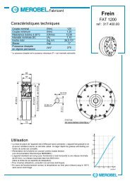
DESIGN PRINCIPLES<br />
PRINCIPE DE CONCEPTION<br />
1 : casing<br />
2 : reaction sleeve<br />
3 : central shaft<br />
A and B : number of teeth in sun gears<br />
a and b : number of teeth in planet gears<br />
1 : cage<br />
2 : douille planétaire<br />
3 : moyeu planétaire<br />
A et B : nombre de dents des planétaires<br />
a et b : nombre de dents des satellites<br />
The REDEX epicyclic unit is comprised of three principal<br />
elements, as follows :<br />
- the casing which carries the planets<br />
- the reaction sleeve / sun gear<br />
- the central shaft / sun gear<br />
The relationship between the angular speeds of these elements<br />
is given by the Willis formula :<br />
n1 : angular speed of casing and planet assemblies<br />
n2 : angular speed of reaction sleeve / sun gear<br />
n3 : angular speed of central shaft / sun gear<br />
ρ : gear ratio relating n2 to n3<br />
When the SR unit is used as a simple Reducer, the reduction<br />
ratio is given by the formula :<br />
86<br />
reduction ratio i<br />
rapport de réduction i<br />
i is positive for ρ < 1<br />
n3 same direction of rotation as n1<br />
i is negative for ρ > 1<br />
n3 reverse direction of rotation to n1<br />
When the SR unit is used as a differential, apply the formula<br />
:<br />
n3 is the output shaft<br />
www.redex-andantex.com<br />
n3 - n1<br />
n2 - n1<br />
=<br />
n1<br />
n3 =<br />
SR SERIES - Differentials and Reducers<br />
SERIE SR - Différentiels et Reducteurs<br />
Le train épicycloïdal REDEX se compose des trois éléments<br />
principaux suivants :<br />
- la cage porte-satellites<br />
- la douille planétaire<br />
- le moyeu planétaire<br />
La formule de Willis donne la relation qui existe entre les<br />
trois vitesses de rotation :<br />
A - b<br />
= ρ =<br />
a - B<br />
n1 : vitesse de la cage porte satellites<br />
n2 : vitesse de la douille planétaire<br />
n3 : vitesse du moyeu planétaire<br />
ρ : raison du train d’engrenages reliant n2 à n3<br />
Lorsque le module SR est utilisé en REDUCTEUR, le rapport<br />
de réduction est donné par la formule :<br />
1<br />
1 - ρ<br />
n3 = ρ n2 + n1 (1- ρ)<br />
for / pour n2 = 0<br />
i est positif pour ρ < 1<br />
n3 même sens de rotation que n1<br />
i est négatif pour ρ > 1<br />
n3 sens de rotation inverse à n1<br />
1<br />
Lorsque le module SR est utilisé en DIFFERENTIEL, utiliser la<br />
formule :<br />
n3 est élément récepteur<br />
2<br />
3<br />
a b<br />
A B<br />
All data subject to change without notice<br />
Données susceptibles d’être modifiées sans préavis
SR Series Série SR<br />
SR SERIES - Differentials and Reducers<br />
SERIE SR - Différentiels et Reducteurs<br />
Based on the required torque T1 (machine shaft)and the<br />
opposite coefficients, the corrected Torque (T) is given by<br />
the formula :<br />
T = T1 x Ka x Ki x Ks x Kd<br />
Select the units so that the torque shown on the table<br />
below is greater than the result T<br />
A partir du couple demandé T1, et en utilisant les coefficients<br />
ci-contre, le couple corrigé (T) est donné par la formule :<br />
T = T1 x Ka x Ki x Ks x Kd<br />
Le choix des appareils doit être tel que le couple indiqué<br />
sur la table ci-dessous soit supérieure au résultat T<br />
MAX. ALLOWED TORQUE<br />
COUPLE MAXIMUM ADMISSIBLE<br />
Unit size Torque<br />
Taille<br />
Couple<br />
daNm<br />
NUMBER OF TEETH (from size 18 up to size 95)<br />
NOMBRE DE DENTS (pour taille 18 à taille 95)<br />
Gear reference number<br />
Numéro du jeu<br />
SELECTION & NUMBER OF TEETH<br />
SELECTION & TABLEAU DU NOMBRE DE DENTS<br />
1 2 3 4 5 6 7 8<br />
Sungear A<br />
Planétaire A 45 37 40 36 35 38 40 36<br />
No of teeth<br />
Nb de dents<br />
Central<br />
shaft bore<br />
Alésage<br />
moyeu<br />
Casing<br />
diameter<br />
Diamètre<br />
cage<br />
18 6 18 121<br />
20 24.5 20 156<br />
30 73.5 30 209<br />
42 206 42 275<br />
56 471 56 355<br />
75 1118 75 450<br />
95 2384 95 580<br />
130 4709 130 700<br />
165 10004 165 855<br />
240 28254 240 1300<br />
SERVICE FACTOR<br />
FACTEUR DE SERVICE<br />
Electric motor<br />
Moteur électrique<br />
Hours<br />
Heures<br />
uniform<br />
load<br />
Charge<br />
uniforme<br />
I<br />
Planet Gear a<br />
Satellite a 20 26 28 25 23 26 24 32<br />
Sungear B<br />
Planétaire B 45 37 40 36 35 38 40 36<br />
Planet Gear b<br />
Satellite b 20 26 28 25 23 26 24 32<br />
Moderate<br />
shock<br />
Surcharge<br />
modérée<br />
II<br />
1.00 1.17 1.60<br />
3 000 8 000 15 000 25 000 50 000<br />
1.00 1.10 1.20 1.26 1.37<br />
www.redex-andantex.com<br />
Standard Gears<br />
Pignons standard<br />
Semi-standard Gears<br />
Pignons semi-standard<br />
Each internal ratio ρ (or I) has a corresponding gear combination C comprising two sets of numbers (see table above).<br />
The two numbers of the combination give the respective numbers of teeth in the sun and planet gears : A-a and B-b.<br />
Example : ρ = 0.9351 (I=15.42) combination C:25 (A = 37 teeth, a = 26 teeth, B = 35 teeth, b = 23 teeth).<br />
Heavy<br />
shock<br />
Surcharge<br />
importante<br />
III<br />
A chaque raison ρ (ou rapport I) correspond une combinaison C, constituée de deux numéros de jeu (tableau ci-dessus).<br />
Les deux chiffres de la combinaison donnent respectivement les nombres de dents des planétaires et des satellites : A-a et B-b.<br />
Exemple : ρ = 0.9351 (I=15.42) combinaison C:25 (A = 37 dents, a = 26 dents, B = 35 dents, b = 23 dents).<br />
Ka<br />
SERVICE LIFE FACTOR<br />
COEFFICIENT DE DUREE DE VIE<br />
Ki<br />
WORKING TIME / DAY FACTOR<br />
COEFFICIENT DE FONCT. JOURNALIER Ks<br />
8 h / 24 16 h / 24 24 h / 24<br />
I 1.00 1.10 1.15<br />
II 1.00 1.27 1.35<br />
III<br />
1.00 1.18 1.33<br />
DYNAMIC FACTOR<br />
COEFFICIENT DE DYNAMIQUE<br />
N# of starts per hour<br />
Nb de démarrages / heure<br />
n < 5 5 < n < 30<br />
Kd<br />
8 h / 24 16 h / 24 24 h / 24<br />
1.01 1.13 1.18 1.21<br />
87
ORDERING CODE<br />
CODIFICATION<br />
Type / Type<br />
SR SR<br />
Size / Taille<br />
Hollow bore / Diam. alésage Ø 18 18<br />
Hollow bore / Diam. alésage Ø 20 20<br />
Hollow bore / Diam. alésage Ø 30 30<br />
Hollow bore / Diam. alésage Ø 42 42<br />
Hollow bore / Diam. alésage Ø 56 56<br />
Hollow bore / Diam. alésage Ø 75 75<br />
Hollow bore / Diam. alésage Ø 95 95<br />
Hollow bore / Diam. alésage Ø 130 130<br />
Hollow bore / Diam. alésage Ø 165 165<br />
Hollow bore / Diam. alésage Ø 240 240<br />
No of planets / Nombre de planétaires<br />
2<br />
3<br />
4<br />
6<br />
8<br />
12<br />
88<br />
Ex. : SR 30 .4 . K-6 .C73 .82HTD8x38 .DP<br />
www.redex-andantex.com<br />
2<br />
3<br />
4<br />
6<br />
8<br />
12<br />
Angular backlash / Jeu angulaire<br />
Standard < 30 arcm. -<br />
Reduced / Réduit
SR Series Série SR<br />
SR SERIES - Differentials and Reducers<br />
SERIE SR - Différentiels et Reducteurs<br />
Size<br />
Taille<br />
SR 18<br />
SR 20<br />
SR 30<br />
SR 42<br />
SR 56<br />
SR 75<br />
SR 95<br />
SR 130<br />
SR 165<br />
SR 240<br />
RATED TORQUE (on central shaft) T2N Nm<br />
COUPLE NOMINAL T2N (au moyeu planétaire) Nm<br />
No of planets<br />
Nb de satellites<br />
CHECKING THE THERMAL POWER !<br />
VERIFICATION DE LA PUISSANCE THERMIQUE !<br />
The thermal power corresponds to the transmissible power of<br />
the REDEX Unit taking into account its efficiency and capacity<br />
to dissipate internal heat generated.<br />
For the chosen i ratio, check that the transmitted power on<br />
the machine shaft is equal to or less than the corresponding<br />
value given in the next pages tables.<br />
The thermal power given in the tables is the average transmitted<br />
power per hour at the unit’s central shaft for an<br />
ambient temperature of 25°C.<br />
EXAMPLE :<br />
Hourly factor running 85% (running 51 mn/h)<br />
Average power per hour : 4.5 x 0.85 = 3.83 kW.<br />
Thermal power acceptable by the Unit : 4.04 kW.<br />
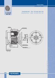
Casing Speed / Vitesse de cage<br />
TORQUE TABLE<br />
TABLE DES COUPLES<br />
100 200 300 350 400 450 550 650 800 1000 100 1500 1800<br />
3 30 30 30 30 30 30 30 29 29 28 0.0023 1.6<br />
6 60 60 60 60 60 60 60 58 58 56 0.0026 1.85<br />
2 98 98 98 98 98 98 98 98 98 98 93 78 69 0.029 6.6<br />
3 147 147 147 147 147 147 147 147 147 147 140 120 103 0.029 6.9<br />
4 196 196 196 196 196 196 196 196 196 196 186 157 137 0.029 7.2<br />
6 245 245 245 245 245 245 245 245 245 245 245 235 206 0.03 7.8<br />
2 245 245 245 245 238 230 220 210 206 196 186 177 0.137 12.3<br />
3 367 367 367 367 356 345 330 315 309 294 279 265 0.14 13<br />
4 490 490 490 490 475 460 440 420 412 392 372 354 0.142 13.6<br />
6 735 735 735 735 713 690 660 630 618 588 558 530 0.147 15<br />
2 680 680 680 680 680 680 680 680 630 560 530 0.41 40<br />
3 1030 1030 1030 1030 1030 1030 1030 1030 950 840 790 0.42 41.5<br />
4 1370 1370 1370 1370 1370 1370 1370 1370 1270 1120 1060 0.43 43<br />
6 2060 2060 2060 2060 2060 2060 2060 2060 1910 1680 1590 0.44 46<br />
2 1570 1570 1570 1570 1570 1570 1570 1570 1390 1.42 85<br />
3 2350 2350 2350 2350 2350 2350 2350 2350 2090 1.45 89<br />
4 3140 3140 3140 3140 3140 3140 3140 3140 2780 1.48 92<br />
6 4710 4710 4710 4710 4710 4710 4710 4710 4180 1.54 99<br />
2 3720 3720 3720 3720 3580 3430 3090 2600 4.67 190<br />
3 5590 5590 5590 5590 5370 5150 4630 3900 4.82 200<br />
4 7460 7460 7460 7460 7160 6860 6180 5200 4.97 210<br />
6 11180 11180 11180 11180 10740 10300 9270 7800 5.28 230<br />
2 7950 7950 7950 7950 7950 7950 7950<br />
15.05 390<br />
3 11920 11920 11920 11920 11920 11920 11920<br />
15.78 416<br />
4 15890 15890 15890 15890 15890 15890 15890<br />
16.51 442<br />
6 23840 23840 23840 23840 23840 23840 23840<br />
17.98 495<br />
4 23540 23540 23540 21550 19620 38.5 578<br />
6 35320 35320 35320 32360 29420 40 610<br />
8 47090 47090 47090 43150 39230 41.7 626<br />
6 50020 50020 50020 50020<br />
72 820<br />
8 66700 66700 66700 66700<br />
75 860<br />
10 83370 83370 83370 83370<br />
79 900<br />
12 100040 100040 100040 100040<br />
82 940<br />
6 141270 141270 141270<br />
638 3648<br />
8 188360 188360 188360<br />
675 3800<br />
10 235450 235450 235450<br />
712 3952<br />
12 282540 282540 282540<br />
775 4104<br />
-1<br />
min<br />
La puissance thermique correspond à la puissance transmissible<br />
par le module REDEX compte tenu de son rendement et<br />
de sa capacité d’évacuation calorifique.<br />
Pour le rapport i considéré, vérifier que la puissance moyenne<br />
utile à l’arbre de la machine soit inférieure ou égale à la<br />
valeur correspondante des tableaux pages suivantes.<br />
La puissance thermique indiquée dans ces tableaux représente<br />
la moyenne horaire admissible au moyeu du module<br />
REDEX pour une température ambiante de 25°C.<br />
EXEMPLE :<br />
Service intermittent 85% (fonctionnement 51 mn/h)<br />
Puissance moyenne horaire : 4.5 x 0.85 = 3.83 kW.<br />
Puissance thermique admissible par le module : 4.04 kW.<br />
www.redex-andantex.com<br />
2<br />
kg.m<br />
Inertia / casing<br />
Inertie / cage<br />
Weight<br />
Masse kg<br />
89
POWER, RATIO, EFFICIENCY<br />
PUISSANCES, RAPPORTS, RENDEMENT<br />
SR 18 SR 20 SR 30 SR 42 SR 56 SR 75 SR 95<br />
i i ρ c η sc rc sc rc sc rc sc rc sc rc sc rc sc rc<br />
2 * 0.5 81 0.98 2.89 4.4 2.25 7.36 4.04 13.2 7.1 23.2 11.84 38.7 17.2 56.25 32 105<br />
2.72 0.6325 21 0.97 2.25 7.36 4.04 13.2 7.1 23.2 11.84 38.7 17.2 56.25 32 105<br />
3.83 0.7392 85 0.95 2.25 7.36 4.04 13.2 7.1 23.2 11.84 38.7 17.2 56.25 32 105<br />
4.7 0.7875 83 0.93 2.25 5.44 4.04 10.5 7.1 17.3 11.84 27.33 17.2 43.84 32 73.73<br />
6 * 1.1667 73 0.9 2.89 4.4 2.25 3.69 4.04 7.11 7.1 11.7 11.84 18.45 17.2 29.7 32 49.95<br />
10.5 * 1.0952 75 0.84 2.89 2.58 2.25 2.15 4.04 4.14 7.1 6.82 11.84 10.76 17.2 17.32 32 29.13<br />
15.42 0.9351 25 0.79 2.25 1.54 4.04 2.97 7.1 4.89 11.84 7.71 17.2 12.41 32 20.87<br />
18.61 0.9462 45 0.76 2.25 1.29 4.04 2.5 7.1 4.11 11.84 6.49 17.2 10.45 32 17.57<br />
25.27 0.9605 65 0.69 2.25 0.91 4.04 1.75 7.1 2.89 11.84 4.56 17.2 7.34 32 12.35<br />
38 * 0.9736 26 0.6 2.89 0.77 2.25 0.61 4.04 1.18 7.1 1.95 11.84 3.07 17.2 4.95 32 8.32<br />
43.33 1.0231 63 0.56 2.25 0.52 4.04 1 7.1 1.65 11.84 2.6 17.2 4.2 32 7.06<br />
67.85 0.9852 46 0.45 2.25 0.33 4.04 0.64 7.1 1.06 11.84 1.67 17.2 2.7 32 4.54<br />
125 * 1.008 43 0.31 2.89 0.22 2.25 0.18 4.04 0.35 7.1 0.58 11.84 0.92 17.2 1.48 32 2.49<br />
260 * 0.9961 23 0.18 2.89 0.11 2.25 0.09 4.04 0.17 7.1 0.28 11.84 0.45 17.2 0.72 32 1.21<br />
Losses max<br />
Pertes maxi<br />
90<br />
Qt kW (3)<br />
i Standard internal Ratio / Rapports de réduction standards<br />
* Exact ratio / Rapport exact<br />
ρ Internal ratio / Raison interne<br />
C Combination / Combinaison<br />
η Running efficiency / Rendement en marche (2)<br />
sc Thermal power (stationary casing) / Puissance thermique (cage fixe) kW<br />
rc Thermal power (rotating casing) / Puissance thermique (Cage tournante) kW<br />
For i > 43.33 the REDEX unit is irreversible.<br />
(Used as a reducer : reaction sleeve 2 blocked)<br />
(1) The thermal power given corresponds to the average<br />
power transmitted per hour at the central shaft, when<br />
reaction sleeve 2 blocked, for an ambient temperature<br />
of 25°C and the standard number of grooves in the casing<br />
as given in the table on page 100.<br />
(2) Available data for reaction sleeve 2 blocked.<br />
(3) Qt indicates the average losses permissible per hour for<br />
ambient temperature 25°C.<br />
www.redex-andantex.com<br />
SR SERIES - Differentials and Reducers<br />
SERIE SR - Différentiels et Reducteurs<br />
THERMAL POWER / PUISSANCE THERMIQUE - kW (1)<br />
0.09 0.49 0.07 0.4 0.13 0.8 0.22 1.3 0.37 2.05 0.53 3.3 1 5.5<br />
Pour i > 43.33 le module REDEX est irréversible.<br />
(Utilisation en réducteur : douille planétaire 2 bloquée)<br />
(1) La puissance thermique indiquée correspond à la puissance<br />
moyenne horaire admissible au moyeu avec une<br />
température ambiante de 25°C et un nombre de gorges<br />
standard tel que défini dans le tableau de la page 100.<br />
(2) Données valables pour douille planétaires 2 bloquée<br />
(3) Les pertes Qt indiquées correspondent à une moyenne<br />
horaire admissible pour une température ambiante de<br />
25°C.<br />
All data subject to change without notice<br />
Données susceptibles d’être modifiées sans préavis
SR Series Série SR<br />
SR SERIES - Differentials and Reducers<br />
SERIE SR - Différentiels et Reducteurs<br />
POWER, RATIO, EFFICIENCY<br />
PUISSANCES, RAPPORTS, RENDEMENT<br />
SR 130 SR 165 SR 240<br />
i ρ c η sc rc i ρ c η sc rc i ρ c η sc rc<br />
3.23 0.69109 31 0.95 29 95 3.45 0.7101 31 0.95 81.5 266 2.33 0.5711 21 0.97 196 642<br />
3.27 0.69438 41 0.95 29 95 3.52 0.7165 41 0.94 81.5 266 2.59 0.6142 31 0.96 196 642<br />
3.33 0.70040 81 0.95 29 95 3.56 0.7194 81 0.94 81.5 266 2.72 0.6334 61 0.96 196 642<br />
3.47 0.71196 51 0.95 29 95 3.68 0.7285 51 0.94 81.5 266 2.748 0.6361 91 0.96 196 642<br />
3.88 0.74259 61 0.94 29 95 4.11 0.7568 61 0.94 81.5 266 2.792 0.6418 81 0.96 196 642<br />
5.25 0.80978 71 0.92 29 69 5.52 0.8188 71 0.92 81.5 241 3.21 0.6886 41 0.95 196 642<br />
6.82 0.8534 37 0.9 29 53 7.52 0.8671 37 0.89 81.5 160 5.85 0.8293 24 0.91 196 284<br />
7.017 0.8574 47 0.89 29 51.5 8 * 0.875 47 0.88 81.5 147 9.06 0.8897 28 0.86 196 180<br />
7.4 0.8649 87 0.88 29 50 8.23 0.8785 87 0.88 81.5 140 9.25 * 0.8919 34 0.86 196 179<br />
8.27 0.8792 57 0.87 29 44 9.06 0.8897 57 0.88 81.5 137 9.58 0.8957 25 0.85 196 165<br />
12.05 0.917 67 0.82 29 29 13.2* 0.9242 67 0.82 81.5 86 10.16 0.9016 26 0.83 196 141<br />
14.41 0.9306 36 0.79 29 27 16.2 0.9382 36 0.77 81.5 66 12.46 0.9198 64 0.82 196 124<br />
15.4 0.935 46 0.79 29 24 18.76 0.94672 46 0.76 81.5 59 13.1 l 0.9237 94 0.8 196 116<br />
17.61 0.9432 86 0.78 29 21 20.23 0.95058 86 0.74 81.5 53 14.25* 0.9298 23 0.79 196 101<br />
24.24 0.9587 56 0.69 29 15 26.76 0.96263 56 0.68 81.5 41 14.72 0.9321 84 0.78 196 99<br />
34.1 0.9706 35 0.61 29 11 39.51 0.9746 35 0.59 81.5 27 23.2 * 0.9569 38 0.69 196 65<br />
40.5 * 0.9753 45 0.60 29 9.5 60.5 * 0.9834 45 0.48 81.5 18 29 * 0.9655 39 0.63 196 52<br />
61.71 0.98379 85 0.48 29 6 77.17 0.987 38 0.43 81.5 13.25 33 * 0.9697 36 0.61 196 45<br />
75 * 0.9866 38 0.4 29 5 79.9 0.9874 85 0.42 81.5 13 75.75 0.9868 68 0.4 196 18<br />
115.9 0.99137 48 0.31 29 3.2 112. 0.991 34 0.33 81.5 9.5 112 * 0.9911 98 0.32 196 12<br />
210.6 0.99520 34 0.15 29 1.8 246 * 0.9959 48 0.19 81.5 4.1 232 * 0.9957 69 0.18 196 5.5<br />
Losses max<br />
Pertes maxi<br />
Qt kW (3)<br />
THERMAL POWER / PUISSANCE THERMIQUE - kW (1)<br />
Losses max<br />
Losses max<br />
0.90 6.80 Pertes maxi<br />
Qt kW (3) 2.50 19 Pertes maxi<br />
Qt kW (3) 6 29<br />
i Standard internal Ratio / Rapports de réduction standards<br />
* Exact ratio / Rapport exact<br />
ρ Internal ratio / Raison interne<br />
C Combination / Combinaison<br />
η Running efficiency / Rendement en marche (2)<br />
sc Thermal power (stationary casing) / Puissance thermique (cage fixe) kW<br />
rc Thermal power (rotating casing) / Puissance thermique (Cage tournante) kW<br />
For i > 43.33 the REDEX unit is irreversible.<br />
(Used as a reducer : reaction sleeve 2 blocked)<br />
(1) The thermal power given corresponds to the average<br />
power transmitted per hour at the central shaft, when<br />
reaction sleeve 2 blocked, for an ambient temperature<br />
of 25°C and the standard number of grooves in the casing<br />
as given in the table on page 100.<br />
(2) Available data for reaction sleeve 2 blocked.<br />
(3) Qt indicates the average losses permissible per hour for<br />
ambient temperature 25°C.<br />
Pour i > 43.33 le module REDEX est irréversible.<br />
(Utilisation en réducteur : douille planétaire 2 bloquée)<br />
(1) La puissance thermique indiquée correspond à la puissance<br />
moyenne horaire admissible au moyeu avec une<br />
température ambiante de 25°C et un nombre de gorges<br />
standard tel que défini dans le tableau de la page 100.<br />
(2) Données valables pour douille planétaires 2 bloquée<br />
(3) Les pertes Qt indiquées correspondent à une moyenne<br />
horaire admissible pour une température ambiante de<br />
25°C.<br />
www.redex-andantex.com<br />
91
RADIAL LOADS<br />
CHARGES RADIALES<br />
MAX. RADIAL LOADS F1 & F2 [N] for relative rotation speed ∆n [min -1 ]<br />
CHARGES RADIALES F1 & F2 MAX. [N] pour vitesse relative ∆n [min -1 ]<br />
SR 18<br />
SR 20<br />
SR 30<br />
SR 42<br />
SR 56<br />
SR 75<br />
92<br />
10 16 25 63 100 200 320 500 630 800 1000 1250 1600<br />
F1 2500 2100 1900 1300 1100 900 750 650 600 550 500<br />
F2 4100 3500 3100 2400 2000 1700 1400 1200 1100 1000 900<br />
F1 1700 1700 1700 1700 1700 1350 1150 950 880 810 750 700 640<br />
F2 8000 6900 6000 4500 4050 3240 2800 2400 2300 2100<br />
F1 2600 2600 2600 2600 2600 2200 1800 1350 1300 1050 900 870 850<br />
F2 12000 10500 9100 6800 6100 4900 4250 3650 3450 3200<br />
F1 7200 7200 7200 7200 6200 5000 4300 3700 3300 3100 3000 2900<br />
F2 15500 13400 11600 8750 7300 6250 5400 4640 4400 4050<br />
F1 10700 10700 10700 10700 9200 7350 6300 5400 5000 4650<br />
F2 36300 31300 27300 20500 14700 12700 10900 10350<br />
F1 12800 12800 12800 12800 10900 8750 7500 6400 5950<br />
F2 51150 44250 38450 28910 25800 20700 17900<br />
F1 16100 16100 16100 16100 13800 11000 9450 8100<br />
SR 95 37<br />
F2 64800 56100 48700 36600 32750 26250<br />
F1 59800 59800 59800 59800 51000 40700 35000<br />
SR 130 A B<br />
58 69<br />
F2 89000 77000 67000 50300 45000<br />
SR 165<br />
F1 65500 65500 65500 60700 52000 41500 35500<br />
F2 124000 107000 93000 69750<br />
F1 303000 303000 303000 220000 200000 163000 140000<br />
SR 240 57 91<br />
F2 283000 245000 213000 160000<br />
The design of the REDEX unit does not permit axial loads<br />
to be sustained.<br />
The table above gives the allowable radial loads in relation<br />
to the relative speeds of the REDEX internal components<br />
for a life 15 000 hours.<br />
Average allowable radial load on casing F2<br />
Calculate the maximum relative speed between the<br />
casing and central shaft or reaction sleeve (algebraic<br />
difference).<br />
Allowable radial load on reaction sleeve F1<br />
Calculate the relative speed between central shaft and<br />
reaction sleeve (algebraic difference)<br />
www.redex-andantex.com<br />
∆n<br />
SR SERIES - Differentials and Reducers<br />
SERIE SR - Différentiels et Reducteurs<br />
F2<br />
A B<br />
15 13<br />
18 18<br />
17 25<br />
28<br />
26<br />
28<br />
34<br />
39 45<br />
De par sa conception, le module REDEX n’admet pas de<br />
charges axiales.<br />
Le tableau ci-dessus indique la charge radiale admissible<br />
en fonction de la vitesse relative entre les éléments constitutifs<br />
du module REDEX, pour une durée de vie théorique<br />
de 15 000 heures.<br />
Charge radiale maxi admissible sur la douille F2<br />
Calculer la vitesse relative entre le moyeu et la douille<br />
(différence algébrique des vitesses)<br />
Charge radiale maxi admissible sur la cage F1<br />
Calculer la vitesse relative entre la cage et le moyeu ou<br />
la douille (différence algébrique des vitesses)<br />
F1<br />
30<br />
60<br />
75<br />
All data subject to change without notice<br />
Données susceptibles d’être modifiées sans préavis
SR Series Série SR<br />
SR SERIES - Differentials and Reducers<br />
SERIE SR - Différentiels et Reducteurs<br />
Size<br />
Taille<br />
S<br />
P9<br />
ØB<br />
ØG<br />
R H7<br />
K<br />
ØP<br />
Standard = flat casing<br />
Alternative designs, see next pages<br />
T<br />
A<br />
C D<br />
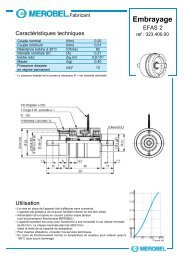
BASIC DIMENSIONS<br />
DIMENSIONS VERSION DE BASE<br />
E F<br />
H mini<br />
Standard = cage lisse<br />
Autres éxecutions, voir pages suivantes<br />
Z<br />
Ø33<br />
1,6<br />
35<br />
www.redex-andantex.com<br />
6<br />
P9 x 3<br />
1<br />
27 6<br />
A B C D E F G H K P R S<br />
[1]<br />
T<br />
g6<br />
Ø35<br />
Z<br />
splines / canelures<br />
[2]<br />
SR 18 100 121 63 35 35 1 2 18 20.8 6 29<br />
SR 20 137 156 94 41 30.5 3.8 40 0.2 2 20 22.8 6 43 40 x 30 x 1.25<br />
SR 30 157 209 110 45 36.4 4.1 55 0.2 2 30 33.3 8 52 55 x 31 x 1.667<br />
SR 42 226 275 156 58 46 6.65 75 0.2 12 42 45.3 12 80 75 x 28 x 2.5<br />
SR 56 296 355 200 76 58 9.15 100 0.2 20 56 60.3 16 95 100 x 38 x 2.5<br />
SR 75 367 450 255 92 60 13 125 1.5 20 75 79.9 20 115 125 x 31 x 3.75 [3]<br />
SR 95 460 580 330 96 60 14 160 1.5 34 95 100.4 25 150 160 x 30 x 5<br />
SR 130 512 700 356 115 68 13.15 205 2 41 130 137.4 32 195 200 x 38 x 5<br />
SR 165 550 855 404 103 68 13.15 240 4.5 43 165 174.4 40 230 240 x 30 x 7.5<br />
SR 240 730 1300 520 180 80 33 380 2.7 30 240 252.4 56 410 380 x 36 x 10<br />
SR18<br />
[3] Non standard : distance across 5 teeth equals<br />
Hors standards : cotes sur 5 dents<br />
[1] NF E22 175<br />
[2] NF E22 141<br />
53.92 -0.013<br />
-0.071<br />
93
SPECIFIC DIMENSIONS<br />
DIMENSIONS SPECIFIQUES<br />
VEE BELTS DRIVE<br />
COURROIE TRAPEZOIDALE<br />
Size<br />
Taille<br />
94<br />
SPZ/Z SPA/A SPB/B SPC/C<br />
Dp N* F E Dp N* F E Dp N* F E Dp N* F E<br />
SR 20 151 5 11 12<br />
SR 30 204 5 13 12 203 5 17.5 15<br />
SR 42 270 5 12 12 269 5 10.5 15 268 6 11.5 19<br />
SR 56 350 5 10 12 349 5 10 15 348 6 14.5 19 345 7 25 25<br />
SR 75 445 5 13.5 12 444 5 15 15 443 6 13.5 19 440 8 15 25<br />
SR 95 574 5 15 15 573 6 13 19 570 8 15 25<br />
SR 130 694 5 58 15 693 6 64 19 690 8 65.5 25<br />
SR 165 849 5 14.5 15 848 6 12 19 845 8 27 25<br />
SR 240 1290 8 22.5 25<br />
* Standard number of grooves (adjacent to reaction sleeve)<br />
Nombre de gorges standard (coté douille planétaire)<br />
POLY-VEE BELT DRIVE<br />
COURROIE POLY-V<br />
10<br />
DP<br />
N grooves / gorges *<br />
www.redex-andantex.com<br />
Size<br />
Taille<br />
SR SERIES - Differentials and Reducers<br />
SERIE SR - Différentiels et Reducteurs<br />
DP<br />
E F<br />
N grooves / gorges<br />
J L M<br />
Dp min. Dp max. Dp min. Dp max. Dp min. Dp max.<br />
SR 20 141 156<br />
SR 30 186 209 192 209<br />
SR 42 251 275 257 275 267 275<br />
SR 56 326 355 336 355<br />
SR 75 416 450 426 450<br />
SR 95 547 580 557 580<br />
* For different values of N consult your supplier<br />
Pour des valeurs de N différentes, consulter votre distibuteur<br />
All data subject to change without notice<br />
Données susceptibles d’être modifiées sans préavis
SR Series Série SR<br />
SR SERIES - Differentials and Reducers<br />
SERIE SR - Différentiels et Reducteurs<br />
PILOT GUIDE FOR ALTERNATIVE DRIVE SOLUTION<br />
INTERFACE POUR AUTRES SYSTEMES D’ENTRAINEMENT<br />
Size<br />
Taille<br />
A B C E F n d<br />
SR 18 121 110 95 4 10 6 M5<br />
SR 20 156 145 132 5 10 6 M6<br />
SR 30 209 194 180 5 12 6 M6<br />
SR 42 275 255 240 6 16 8 M8<br />
SR 56 355 338 320 7 16 12 M10<br />
SR 75 450 425 400 8 20 12 M12<br />
SR 95 580 555 530 10 20 12 M14<br />
SR 130 700 675 650 10 20 16 M14<br />
SR 165 855 835 815 10 20 16 M14<br />
SR 240 1300 1275 1250 10 0 16 M16<br />
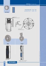
TIMING BELT DRIVE<br />
COURROIE CRANTEE<br />
Size<br />
Taille<br />
SPECIFIC DIMENSIONS<br />
DIMENSIONS SPECIFIQUES<br />
N Teeth / dents<br />
F E<br />
www.redex-andantex.com<br />
ØC /g6<br />
H7<br />
n x Ød ØB 0.1<br />
ØA<br />
L 9.525 H 12.7 XH 22.22 XXH 31.75<br />
De N B A De N B A De N B A De N B A<br />
SR 18 120.5 40 63 10<br />
SR 20 154 51 38 10<br />
SR 30 205.5 68 38 10 204.8 51 90 10<br />
SR 42 272.3 90 38 10 273.6 68 90 10 273.1 39 120 10<br />
SR 56 354.2 117 38 10 354.6 88 90 10 350.9 50 120 10<br />
SR 75 447.4 111 90 10 442.9 63 120 10 441.6 44 140 10<br />
SR 95 564.7 140 90 10 577.3 82 120 10 573 57 140 10<br />
SR 130 697.5 99 120 10 694.2 69 140 10<br />
SR 165 846.1 120 120 10 845.9 84 140 10<br />
De<br />
* n holes Ø d, equidistant.<br />
Location can be on the reaction sleeve side<br />
or central shaft side. Consult your supplier<br />
n trous Ø d, équidistants.<br />
L’emplacement des trous peut être coté<br />
douille planétaire où sur la face opposée.<br />
Consulter votre distributeur.<br />
B<br />
A<br />
*<br />
A : edge of belt<br />
position<br />
position du<br />
bord de<br />
courroie<br />
95
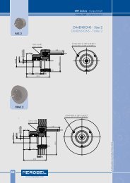
SPECIFIC DIMENSIONS<br />
DIMENSIONS SPECIFIQUES<br />
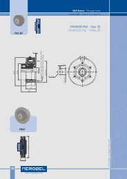
HTD TIMING BELT DRIVE<br />
COURROIE DENTEE HTD<br />
N Teeth / N dents<br />
DP<br />
96<br />
B1<br />
B2<br />
T METRIC BELT<br />
COURROIE DENTEE T<br />
N Teeth / N dents<br />
DP<br />
B1<br />
B2<br />
A =10<br />
A =10<br />
Size<br />
Taille<br />
www.redex-andantex.com<br />
Size<br />
Taille<br />
SR SERIES - Differentials and Reducers<br />
SERIE SR - Différentiels et Reducteurs<br />
HTD 8 HTD 14<br />
N Dp B1 B2 N Dp B1 B2<br />
SR 20 62 156.51<br />
SR 30 82 207.44 47 206.65<br />
SR 42 108 273.65 38 50 62 273.5<br />
SR 56 140 355.14 80 353.71<br />
SR 75 177 449.36 101 447.3<br />
SR 95 130 576.53<br />
A : edge of belt<br />
position<br />
T 5 T 10<br />
50 90<br />
N Dp B1 B2 N Dp B1 B2<br />
SR 20 96 152 48 150.95<br />
SR 30<br />
SR 42<br />
132<br />
172<br />
209.3<br />
272.95<br />
38 50<br />
66<br />
86<br />
208.25<br />
271.9<br />
50 90<br />
SR 56 220 349.35 110 348.3<br />
A : edge of belt<br />
position<br />
position du bord<br />
de courroie<br />
position du bord<br />
de courroie<br />
All data subject to change without notice<br />
Données susceptibles d’être modifiées sans préavis
SR Series Série SR<br />
SR SERIES - Differentials and Reducers<br />
SERIE SR - Différentiels et Reducteurs<br />
REDUCER APPLICATIONS<br />
UTILISATION EN REDUCTEUR<br />
When the unit is used as a reducer the reaction<br />
plate must be secured to a fixed part of the<br />
machine. There is no overload protection with this<br />
arrangement.<br />
Lorsque le module REDEX est utilisé en réducteur,<br />
la rondelle d’arrêt doit être reliée à un élément<br />
fixe de la machine. Cette disposition n’assure<br />
aucune protection en cas de surcharge.<br />
DIFFERENTIAL APPLICATION<br />
UTILISATION EN DIIFFERENTIEL<br />
For differential applications a split clamp plate<br />
can be used to accept the chosen transmission<br />
element.<br />
[1] : 8 holes Ød for socket head screws<br />
8 trous Ød pour vis CHc<br />
Pour une utilisation en différentiel, une rondelle<br />
d’arrêt fendue peut être utilisée comme pièce de<br />
liaison à l’élément de transmission choisi.<br />
[2] : Machine frame<br />
Bâti machine<br />
Size<br />
Taille<br />
Size<br />
Taille<br />
www.redex-andantex.com<br />
ACCESSORIES<br />
ACCESSOIRES<br />
C<br />
D<br />
Ø A<br />
Ø B f7<br />
Ø A Ø B C<br />
SR 20 65 80 12 6.6<br />
SR 30 83 100 12 9<br />
SR 42 110 140 23 14<br />
SR 56 140 180 30 18<br />
SR 75 210 250 40 22<br />
SR 95 275 320 50 24<br />
E<br />
ØF<br />
ØG<br />
D E F G H I<br />
I<br />
Ø d<br />
ØH<br />
SR 18 15,5 14 46 g6 60 72 6xM5 - 60°<br />
SR 20 22,5 14,4 50 f7 66 78 6xM6 - 60°<br />
SR 30 24,7 16 65 f7 86 104 5xM8 - 60°<br />
SR 42 30 21 90 f7 120 145 5xM12 - 60°<br />
SR 56 40,5 26 120 f7 150 175 5xM16 - 60°<br />
SR 75 49,5 28 150 f7 182 215 5xM20 - 60°<br />
[2]<br />
[1]<br />
97
ACCESSORIES<br />
ACCESSOIRES<br />
TORQUE ARM WITH SPRINGS<br />
BRAS DE REACTION ELASTIQUE<br />
Restraining pin<br />
to machine frame<br />
Ergot de retenue<br />
98<br />
Size<br />
Taille<br />
A<br />
V<br />
Machine frame<br />
Côté machine<br />
C<br />
www.redex-andantex.com<br />
B<br />
Ø A<br />
U ± 0.5<br />
A B C U V X<br />
SR 20 36,5 55 10 140 20 20<br />
SR 30 40 72 14 180 22 22<br />
SR 42 50,5 105 23 220 38 26<br />
SR 56 66 140 29 290 38 36<br />
SR 75 77 200 30 350 60 40<br />
SR 95 80 290 15 420 60 50<br />
SR 130 98 350 28 600 80 75<br />
SR 165 89 400 32 800 110 90<br />
SR SERIES - Differentials and Reducers<br />
SERIE SR - Différentiels et Reducteurs<br />
When fitted to the reaction sleeve, the torque arm<br />
holds the sleeve stationary.<br />
By introducing some elasticity into the drive system,<br />
the torque arm dampens shock loads and vibrations.<br />
The leaf springs, which are selected in accorance<br />
with the unit torque rating, provide a flexible link<br />
between the reaction sleeve and the restraining<br />
pin as well as an overload protection (by breaking<br />
the spring).<br />
In case of spring breakage, the machine is no longer<br />
driven by the unit, and the torque arm must be<br />
able to rotate freely.<br />
Le bras de réaction élastique, adapté à la douille<br />
planétaire, permet d’assurer l’immobilisation de<br />
celle ci en rotation.<br />
Par sa capacité à introduire une certaine élasticité<br />
dans la chaîne cinématique, cet accessoire amortit<br />
les à-coups et les vibrations.<br />
Le ressort à lames, défini en fonction du couple<br />
maximal à transmettre, permet d’assurer cette liaison<br />
élastique, en même temps qu’une protection<br />
en cas de surcharge accidentelle (par la rupture<br />
des lames du ressort).<br />
Dans ce dernier cas, la machine n’est plus entraînée<br />
et le bras doit pouvoir tourner librement.<br />
NOTE : the restraining pin must be securely tightened<br />
in order to whistand the high load level -F (N) -<br />
which may be applied on it.<br />
F (N) =<br />
.C ρ<br />
U<br />
NOTA : l’ergot de retenue doit être solidement<br />
fixé pour résister à l’effort important -F (N) - qu’il<br />
peut être amené à supporter.<br />
All data subject to change without notice<br />
Données susceptibles d’être modifiées sans préavis
SR Series Série SR<br />
SR SERIES - Differentials and Reducers<br />
SERIE SR - Différentiels et Reducteurs<br />
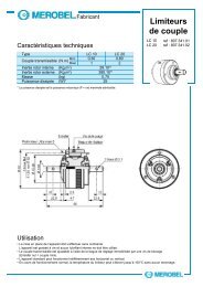
FRICTION TORQUE LIMITOR<br />
LIMTEUR DE COUPLE A FRICTION<br />
Size<br />
Taille<br />
F<br />
ØX<br />
*<br />
C<br />
D<br />
G<br />
Restraining pin<br />
to machine frame<br />
Ergot de retenue<br />
E<br />
ØA<br />
ØB<br />
ØM<br />
A : max. shaft Ø<br />
A : Ø max. de<br />
l’arbre<br />
+<br />
U - 0.5<br />
A B C D E F G M U X<br />
SR 20 40 114 10 42 5.5 143.5 24 224 140 20<br />
SR 30 55 114 10 47.5 5.5 165 24 224 180 22<br />
SR 42 75 148 12 43.5 22.5 234 41 288 220 26<br />
SR 56 100 210 16 53 27 300 43 380 290 36<br />
SR 75 125 260 20 67 23 365 41 490 350 40<br />
SR 95 160 295 24 75 43 482 64 580 420 50<br />
SR 130 200 440 30 95 96 588 123.5 800 600 75<br />
SR 165 240 630 80 127 12 586 37 850 790 95<br />
www.redex-andantex.com<br />
ACCESSORIES<br />
ACCESSOIRES<br />
The REDEX friction torque limiter<br />
is based on a mono-disc<br />
design. Overload protection<br />
is obtained by slippage when<br />
loads exceeding the rated<br />
torque value. The use of the<br />
limiter is recommanded when<br />
the driven machine is subject<br />
to frequent, and possibly dangerous,<br />
overloads.<br />
The torque limitor is delivered after<br />
calibration for the related unit’s max<br />
acceptable torque.<br />
The restraining pin must be securely<br />
tightened in order to whistand the<br />
high load load level -F (N) - which may<br />
be applied on it.<br />
F (N) =<br />
.C ρ<br />
U<br />
Le limiteur de couple à friction REDEX<br />
est du type monodisque. La protection<br />
est obtenue par glissement au<br />
delà du couple d’étalonnage. Cet<br />
accessoire est conseillé lorsque la<br />
machine est soumise à des surcharges<br />
fréquentes et dangereuses pour<br />
l’installation.<br />
Le limiteur de couple REDEX est livré<br />
étalonné pour le couple MAXI que<br />
peut supporter le module.<br />
L’ergot de retenue doit être solidement<br />
fixé pour résister à l’effort<br />
important -F (N) - qu’il peut être<br />
amené à supporter.<br />
99
MOUNTING RECOMMENDATIONS<br />
RECOMMANDATIONS DE MONTAGE<br />
CANTILEVER MOUNTING<br />
MONTAGE EN PORTE-A-FAUX<br />
Location against shoulder and fixed by<br />
screw and washer<br />
Fixation et blocage sur épaulement par<br />
vis et rondelle<br />
100<br />
www.redex-andantex.com<br />
SR SERIES - Differentials and Reducers<br />
SERIE SR - Différentiels et Reducteurs<br />
THROUGH SHAFT MOUNTING<br />
MONTAGE SUR ARBRE TRAVERSANT<br />
Location against shoulder, and fixed using spacer<br />
Fixation et blocage sur épaulement et entretroise<br />
The accessory fitted to the reaction sleeve must be adjacent to the<br />
bearing to avoid excessive bending of the supporting shaft<br />
L’accessoire monté sur la douille doit être obligatoirement situé du<br />
côté du palier afin de ne pas imposer à l’arbre une contrainte exagérée<br />
à la flexion<br />
All data subject to change without notice<br />
Données susceptibles d’être modifiées sans préavis
SR Series Série SR<br />
SR SERIES - Differentials and Reducers<br />
SERIE SR - Différentiels et Reducteurs<br />
www.redex-andantex.com<br />
NOTES<br />
NOTES<br />
101
CONTENTS<br />
SOMMAIRE DETAILLE<br />
D SERIES - Differential Phase-Shifters<br />
The Differential Phase-Shift gearbox is the heart of a registration<br />
control system.<br />
The design allows the angular position of the output shaft to<br />
be accuraltely adjusted for error correction relative to the<br />
input shaft.<br />
In-line and Right-angle versions are available.<br />
With the addition of a motor and an electronic control, a<br />
fully automated registration control system can easily be<br />
achieved.<br />
OVERVIEW<br />
DESIGN PRINCIPLE /<br />
103<br />
SELECTION 104<br />
ORDERING CODE 105<br />
POWER & TORQUE TABLE 106<br />
CHARACTERISTICS 107<br />
RADIAL LOADS 108<br />
DLO DIMENSIONS 109<br />
DLO.D DIMENSIONS 110<br />
DR DIMENSIONS 111<br />
OPTIONAL OUTPUT MOUNTING FLANGE 112<br />
LUBRICATION 113<br />
102<br />
www.redex-andantex.com<br />
D SERIES - Differential Phase Shifters<br />
SERIE D - Différentiels Positionneurs<br />
SERIE D - Différentiels Positionneurs<br />
Les positionneurs à différentiels REDEX, série DLO et DR, permettent<br />
de corriger, en marche comme à l’arrêt la position angulaire<br />
d’un arbre machine par rapport à un élément ou un mouvement<br />
de référence.<br />
Les différents modèles sont particulièrement étudiés pour réaliser<br />
des systèmes de positionnement ou de calage de registre,<br />
sur des équipements où l’espace disponible et l’encombrement<br />
recherché sont limités, et pour lesquels les possibilités<br />
d’implantation sont multiples.<br />
PRESENTATION<br />
PRINCIPE DE FONCTIONNEMENT /<br />
103<br />
SELECTION 104<br />
CODIFICATION 105<br />
PUISSANCES NOMINALES ET COUPLES 106<br />
SPECIFICATIONS 107<br />
CHARGES RADIALES 108<br />
ENCOMBREMENTS DLO 109<br />
ENCOMBREMENTS DLO.D 110<br />
ENCOMBREMENTS DR 111<br />
OPTION FLASQUE BRIDE EN SORTIE 112<br />
LUBRIFICATION 113<br />
All data subject to change without notice<br />
Données susceptibles d’être modifiées sans préavis
D Series Série D<br />
D SERIES - Differential Phase Shifters<br />
SERIE D - Différentiels Positionneurs<br />
DLO SERIES<br />
SERIE DLO<br />
Version à entrée et sortie coaxiales, qui intègre<br />
sous un carter étanche, un différentiel à<br />
train planétaire de précision et une vis sans<br />
fin, et qui autorise un réglage angulaire illimité<br />
de l’arbre machine.<br />
DLO-D SERIES<br />
SERIE DLO-D<br />
DR SERIES<br />
SERIE DR<br />
DRD SERIES<br />
SERIE DRD<br />
DRI SERIES<br />
SERIE DRI<br />
1<br />
3<br />
DLO<br />
In-Line Series combines a high quality planetary<br />
differential with an irreversible worm gear<br />
in one housing, allowing infinite angular<br />
adjustment of the output shaft.<br />
Same design than the DLO series, with an additional planetary reducer for getting possibility<br />
of an overall ratio 1/1, allowing infinite angular adjustment of the output shaft.<br />
De conception identique au positionneur série DLO sur lequel est rapporté un train planétaire<br />
complémentaire, pour obtenir un rapport de transmission de 1/1 entre les arbres<br />
principaux d’entrée et de sortie.<br />
Right-Angle Series adds a set of high quality KLINGELNBERG HPG-S spiral-bevel gears<br />
to the DLO series design allowing right-angle inputs.<br />
De conception identique au positionneur série DLO sur lequel vient s’ajouter un renvoi<br />
d’angle à denture hélicoïdale de précision type HPG-S KLINGELNBERG.<br />
Right-angle Series adds a slide-dog arrangement on the through shaft to the DR series<br />
design for disengaging of the output shaft.<br />
Intègre un encrabotage simple monté sur l’arbre traversant qui autorise, par action<br />
manuelle le débrayage de l’arbre de sortie.<br />
Right-angle Series adds a double-sided slide-dog arrangement and an extra spiralbevel<br />
gear on the through shaft to the DR series design for forward-neutral-reverse<br />
engagement of the output shaft.<br />
Intègre un encrabotage double et un pignon conique supplémentaire sur l’arbre<br />
transversant qui autorisent, par actions manuelles, le débrayage et l’inversion du sens<br />
de rotation de l’arbre de sortie.<br />
2<br />
F<br />
ØA<br />
OVERVIEW<br />
PRESENTATION GENERALE<br />
4 x ØL<br />
1<br />
3<br />
J<br />
B E<br />
www.redex-andantex.com<br />
K<br />
I<br />
G H<br />
4 x ØU / ØV<br />
2<br />
D<br />
1 2<br />
DLO.D<br />
1 3<br />
DR<br />
1 3<br />
DRD<br />
3<br />
1 3<br />
DRI<br />
ØC<br />
2<br />
2<br />
2<br />
103
DESIGN PRINCIPLE / SIZING<br />
PRINCIPE DE FONCTIONNEMENT / SELECTION<br />
High quality KLINGELNBERG<br />
HPG-S spiral-bevel gears<br />
Renvoi d’angle à denture<br />
hélicoïdale de précision type<br />
HPG-S KLINGELNBERG<br />
REQUIRED DATA<br />
104<br />
Required Output Torque T1<br />
Output Speed n2<br />
Based on the opposite coefficients, the Design<br />
Output Torque (T) is given by the formula :<br />
T = T1 x Ka x Ki x Kt<br />
Select the units so that the torque shown on<br />
the rating tables is greater than the result T<br />
Be sure to check also the result against the<br />
thermal capacity table as well as against the<br />
radial load capacity table.<br />
DONNEES TECHNIQUES REQUISES<br />
Couple Utile de Sortie T1<br />
Vitesse de sortie n2<br />
En utilisant les coefficients ci-contre, le couple<br />
utile corrigé (T) est donné par la formule :<br />
T = T1 x Ka x Ki x Kt<br />
Type DR<br />
Le choix des appareils doit être tel que le<br />
couple indiqué dans les tables soit toujours<br />
supérieur au résultat T<br />
Toujours s’assurer que le choix correspondant<br />
à ce résultat demeure compatible avec les<br />
tables de Puissance thermique et de<br />
Charges radiales maximales.<br />
www.redex-andantex.com<br />
1<br />
D SERIES - Differential Phase Shifters<br />
SERIE D - Différentiels Positionneurs<br />
Input Shaft<br />
Arbre d’Entrée<br />
3<br />
Ring gear<br />
Couronne<br />
dentée<br />
SERVICE FACTOR<br />
FACTEUR DE SERVICE<br />
Electric motor<br />
Moteur électrique<br />
Worm gear phase<br />
adjustment shaft<br />
Vis sans fin de correction<br />
Sun gear<br />
Pignon<br />
planétaire<br />
Planet carrier<br />
SERVICE LIFE FACTOR<br />
COEFFICIENT DE DUREE DE VIE<br />
Cage porte-satellites<br />
Output Shaft<br />
Arbre de Sortie<br />
2<br />
Cast aluminium end cover<br />
Carter en aluminium<br />
uniform<br />
load<br />
Charge<br />
uniforme<br />
Ka<br />
Moderate<br />
shock<br />
Surcharges Surcharges<br />
modérées importantes<br />
1.00 1.25 1.50<br />
Hours<br />
Heures<br />
100 1000 5000 10000 15000 20000 40000<br />
Ki 0.65 0.8 0.95 1 1.05 1.15 1.4<br />
AMBIENT TEMPERATURE FACTOR<br />
COEFFICIENT DE TEMPERATURE<br />
Amb. temp.<br />
° C<br />
Ki<br />
Kt<br />
Heavy<br />
shock<br />
10 25 35 50<br />
Kt 0.85 1.00 1.15 1.4<br />
All data subject to change without notice<br />
Données susceptibles d’être modifiées sans préavis
D Series Série D<br />
D SERIES - Differential Phase Shifters<br />
SERIE D - Différentiels Positionneurs<br />
ORDERING CODE<br />
CODIFICATION<br />
TYPE DESIGNATION<br />
DESIGNATION<br />
MOUNTING POSITIONS<br />
POSITIONS DE MONTAGE<br />
1<br />
DIRECTION OF ROTATION<br />
SENS DE ROTATION<br />
Model designation / Désignation<br />
See table below / Voir table ci-dessous ...<br />
ORDERING CODE<br />
CODIFICATION<br />
ex. DR5-123 3 O H3 C<br />
Ratio / Rapport (i = n1 / n2)<br />
1 DLO-D or / ou DR 1<br />
1.5 DR only / uniquement 1.5<br />
2 DR only / uniquement 2<br />
3 DLO or / ou DR 3<br />
Direction of rotation / Sens de rotation<br />
O O<br />
I I<br />
Mounting position / Position de montage<br />
H1 H1<br />
H2 H2<br />
H3 H3<br />
H4 H4<br />
Flange option / Option flasque bride (p 112)<br />
C C<br />
D D<br />
3<br />
2<br />
1<br />
Type<br />
2<br />
Size / Taille<br />
4 5 6 7 8<br />
DLO DLO103 DLO123 DLO163 DLO213 DLO263<br />
DLO-D DLO103-D DLO123-D DLO163-D DLO213-D DLO263-D<br />
DR DR4-103 DR5-123 DR6-163 DR7-213 DR8-263<br />
DRD DRD5-123 DRD6-163 DRD7-213 DRD8-263<br />
DRI DRI15-125 DRI6-163 DRI7-213 DRI8-263<br />
H1 H2 3<br />
H3 H4<br />
Type DR<br />
1<br />
3<br />
1 3<br />
2<br />
2<br />
Rotation I Rotation O<br />
www.redex-andantex.com<br />
1<br />
3<br />
2<br />
1 3<br />
UP / HAUT<br />
2<br />
105
POWER & TORQUE TABLE<br />
PUISSANCES NOMINALES ET COUPLES<br />
TORQUE CAPACITY AND CORRESPONDING POWER<br />
COUPLE NOMINAL ET PUISSANCE CORRESPONDANTE<br />
Output<br />
speed<br />
min -1<br />
Vitesse de<br />
sortie<br />
20 65 0.142 130 0.284 285 0.622 645 1.407 1350<br />
350 50 1.909 100 3.818 190 7.253 450 17.18 850<br />
1000 35 3.818 70 7.635 135 14.73 375 40.90 640<br />
1500 30 4.908 60 9.817 125 20.45 300 49.08<br />
T2 = output torque<br />
T2 = couple à l’arbre de sortie<br />
P1 n3 T2<br />
n1 n2<br />
106<br />
DLO<br />
THERMAL CAPACITY (kW)<br />
PUISSANCE THERMIQUE (kW)<br />
Type<br />
DLO<br />
DLO-D<br />
DR<br />
Size<br />
Taille 4<br />
6,5<br />
4<br />
3,5<br />
Size / Taille 4 Size / Taille 5 Size / Taille 6 Size / Taille 7 Size / Taille 8<br />
T2 P1 T2 P1 T2 P1 T2 P1 T2 P1<br />
Nm kW Nm kW Nm kW Nm kW Nm kW<br />
Size<br />
Taille 5<br />
8<br />
8<br />
6<br />
www.redex-andantex.com<br />
P1 n3 T2<br />
n1 n2<br />
Size<br />
Taille 6<br />
17<br />
10<br />
12<br />
Size<br />
Taille 7<br />
22,5<br />
13,75<br />
18<br />
DLO.D<br />
Size<br />
Taille 8<br />
30<br />
18,5<br />
25<br />
All powers are in average kW per hour, and are based on continuous running with<br />
an ambient temperature of 25°C.<br />
Toutes les puissances indiquées sont des valeurs moyennes horaires valables pour un<br />
fonctionnement continu à température ambiante 25°C.<br />
D SERIES - Differential Phase Shifters<br />
NOTE : maximum output speed is 1000 min -1 for DLO ratio 3, DR ratios 2 and 3 and DR8 all ratios.<br />
SERIE D - Différentiels Positionneurs<br />
NOTA : Pour les positionneurs série DLO rapport 3, DR rapports 2 et 3 et tous rapports taille 8, la vitesse<br />
maxi de sortie est illimitée à 1000 min -1.<br />
P1 T2<br />
n3<br />
n1<br />
DR<br />
2.95<br />
32.45<br />
69.80<br />
P1 = input power Efficiency = 0.96<br />
P1 = puissance correspondante<br />
à l’arbre d’entrée<br />
Rendement = 0.96<br />
n2<br />
All data subject to change without notice<br />
Données susceptibles d’être modifiées sans préavis
D Series Série D<br />
D SERIES - Differential Phase Shifters<br />
SERIE D - Différentiels Positionneurs<br />
DLO SERIES<br />
SERIE DLO<br />
n1<br />
n3<br />
DLO<br />
n1 n3<br />
DR<br />
n3<br />
n2<br />
n1 : Input shaft / Arbre d’entrée<br />
n2 : Output shaft / Arbre de sortie<br />
n3 : Correction shaft / Vis de correction<br />
DLO-D SERIES<br />
SERIE DLO-D<br />
n1 n2<br />
DLO.D<br />
n1 : Input shaft / Arbre d’entrée<br />
n2 : Output shaft / Arbre de sortie<br />
n3 : Correction shaft / Vis de correction<br />
DR, DRD, DRI SERIES<br />
SERIE DR, DRD, DRI<br />
n2<br />
n1 : Input shaft / Arbre d’entrée<br />
n2 : Output shaft / Arbre de sortie<br />
n3 : Correction shaft / Vis de correction<br />
CHARACTERISTICS<br />
SPECIFICATIONS<br />
Standard ratio / Rapport principal (n1/n2): I = 3<br />
Correction ratio / Rapport de correction : 135 (n3/n2)<br />
Maximum output speed / Vitesse max. de sortie : n2 = 1000 min -1<br />
Maximum correction speed / Vitesse max. de correction : n3 = 1000 min -1<br />
Unit efficiency / Rendement : 0.98 (n1/n2)<br />
0.40 (n3/n2)<br />
Maximum blacklash / Jeu angulaire : ≤ 6 arcmin (n2)<br />
Reduced backlash / Jeu angulaire réduit (option) : ≤ 3 arcmin (n2)<br />
Standard ratio / Rapport principal (n1/n2): I = 1<br />
Correction ratio / Rapport de correction : 135 (n3/n2)<br />
Maximum output speed / Vitesse max. de sortie : n2 = 1500 min-1 except / sauf DLO-D8 n2 = 1000 min-1 Maximum correction speed /Vitesse max. de correction : n3 = 1000 min-1 Unit efficiency / Rendement : 0.96 (n1/n2)<br />
0.40 (n3/n2)<br />
Maximum blacklash / Jeu angulaire : ≤ 9 arcmin (n2)<br />
Standard ratio / Rapport principal (n1/n2): I = 1, 1.5, 2, 3<br />
Correction ratio / Rapport de correction : 135 (n3/n2)<br />
Maximum output speed / Vitesse max. de sortie : n2 = 1500 min-1 except / sauf DR8 n2 = 1000 min-1 Maximum correction speed / Vitesse max. de correction : n3 = 1000 min-1 Unit efficiency / Rendement : 0.96 (n1/n2)<br />
0.40 (n3/n2)<br />
Maximum blacklash / Jeu angulaire : ≤ 9 arcmin (n2)<br />
Reduced backlash / Jeu angulaire réduit (option): ≤ 6 arcmin (n2)<br />
www.redex-andantex.com<br />
107
RADIAL LOADS<br />
CHARGES RADIALES<br />
Speed<br />
Vitesse<br />
min-1<br />
500<br />
1000<br />
1500<br />
2000<br />
2500<br />
3000<br />
108<br />
Fr1 Fr2<br />
n3<br />
n1 n2<br />
DLO<br />
Size / Taille 4 Size / Taille 5 Size / Taille 6 Size / Taille 7 Size / Taille 8<br />
Fr1 Fr1 Fr2 Fr1 Fr1 Fr2 Fr1 Fr1 Fr2 Fr1 Fr1 Fr2 Fr1 Fr1 Fr2<br />
DLO DR DLO DR DLO DR DLO DR DLO DR<br />
650 2000 900 1700 3000 2300 1900 3950 2800 2600 7250 4000 3700 11 250 8750<br />
500 1750 800 1350 2200 1800 1500 3500 2200 2100 6370 3000 3000 10 000 7000<br />
450 1500 700 1150 1900 1600 1250 2910 1800 1750 5820 2500 2500 9100<br />
410 1430 1050 1700 1150 2680 1600 5000 2200 8000<br />
390 1250 1000 1600 1100 2310 1500 4570 2100 7000<br />
370 1070 950 1550 1000 2070 1400 3930 1900 6200<br />
www.redex-andantex.com<br />
Fr1 Fr2<br />
n3<br />
n1 n2<br />
DLO.D<br />
D SERIES - Differential Phase Shifters<br />
SERIE D - Différentiels Positionneurs<br />
Loads Fr1 and Fr2 are in N, and are assumed to be applied at midpoint of the shafts extension. For DLO-D radial load capacity<br />
is Fr2 for input and output shafts.<br />
Les charges radiales Fr1 et Fr2 sont exprimées en N, et correspondent à des efforts appliqués au milieu de chacuns des arbres.<br />
Pour les modèles DLO-D, la charge radiale admissible est identique sur les arbres d’entrée et de sortie.<br />
Fr1 Fr2<br />
n1<br />
DR<br />
n3<br />
n2<br />
All data subject to change without notice<br />
Données susceptibles d’être modifiées sans préavis
D Series Série D<br />
D SERIES - Differential Phase Shifters<br />
SERIE D - Différentiels Positionneurs<br />
T<br />
S<br />
ØM<br />
Size<br />
Taille<br />
w<br />
o<br />
P<br />
N N<br />
Q<br />
R<br />
2<br />
3<br />
M<br />
4 x ØL<br />
ØX<br />
F<br />
ØA<br />
DIMENSIONS - DLO<br />
ENCOMBREMENT DLO<br />
4 x ØL<br />
1<br />
www.redex-andantex.com<br />
3<br />
J<br />
B E<br />
K<br />
I<br />
G H<br />
4 x ØU / ØV<br />
ØAj6 B ØCk6 D E F G H I J K ØL ØMj6<br />
4 17 30 30 52 98 125 40 28,5 48,5 15 15 M6x10 10<br />
5 25 40 35 70 99 160 40 28,5 50,5 16 19 M8x15 10<br />
6 32 50 45 90 150 203 50 49 74 22,5 22,5 M10x12 14<br />
7 40 65 55 110 156 250 60 48 78 22,5 22,5 M12x18 16<br />
8 50 80 70 140 195 315 75 60 97,5 37,5 37,5 M16x24 22<br />
Size<br />
Taille<br />
4<br />
5<br />
6<br />
7<br />
8<br />
N O P Q R S T<br />
ØU ØV W ØXh5<br />
20 72 142 88 100 50 53 M6x6 48 97 30 6<br />
20 80 170 110 125 62,5 67 M6x8 52 120 35 8,5<br />
28 110 222 125 160 80 85 M6x10 70 155 47 21,8<br />
30 130 280 170 200 100 103 M8x12 90 195 52 36,5<br />
44 170 358 210 250 125 135 M10x18 110 244 72 80<br />
Output mounting flange option + shafts end details : see page 112<br />
Option flasque-bride côté sortie + détails des bouts d’arbres : voir page 112<br />
2<br />
D<br />
ØC<br />
Weight<br />
Poids (kg)<br />
109
DIMENSIONS - DLO.D<br />
ENCOMBREMENT DLO.D<br />
T<br />
S<br />
ØM<br />
Size<br />
Taille<br />
110<br />
N<br />
P<br />
w<br />
o<br />
Q<br />
R<br />
2<br />
www.redex-andantex.com<br />
N<br />
3<br />
M<br />
ØX<br />
4 x ØL<br />
F<br />
ØC<br />
4 x ØL<br />
1 2<br />
H G<br />
D E<br />
ØCk6 D E F G H I J K ØL ØMj6<br />
4 30 52 170 125 59 28,5 48,5 15 15 M6x10 10<br />
5 35 70 180 160 68 28,5 50,5 16 19 M8x15 10<br />
6 45 90 260 203 87 49.5 74 22,5 22,5 M10x12 14<br />
7 55 110 290 250 109 48 78 22,5 22,5 M12x18 16<br />
Size<br />
Taille<br />
4<br />
5<br />
6<br />
7<br />
N O P Q R S T<br />
20 72 142 88 100 50 53 M6x6 48 97 30 11<br />
20 80 170 110 125 62,5 67 M6x8 52 120 35 17<br />
28 110 222 125 160 80 85 M6x10 70 155 47 42,5<br />
30 130 280 170 200 100 103 M8x12 90 195 52 71,5<br />
Output mounting flange option + shafts end details : see page 112<br />
Option flasque-bride côté sortie + détails des bouts d’arbres : voir page 112<br />
D SERIES - Differential Phase Shifters<br />
SERIE D - Différentiels Positionneurs<br />
ØU ØV W ØXh5<br />
3<br />
J<br />
K<br />
I<br />
Weight<br />
Poids (kg)<br />
4 x ØU / ØV<br />
D<br />
ØC<br />
All data subject to change without notice<br />
Données susceptibles d’être modifiées sans préavis
D Series Série D<br />
D SERIES - Differential Phase Shifters<br />
SERIE D - Différentiels Positionneurs<br />
T<br />
S<br />
A<br />
Size<br />
Taille<br />
ØM<br />
N<br />
P<br />
w<br />
o<br />
Q<br />
H<br />
B R<br />
B<br />
2<br />
N<br />
3<br />
M<br />
1<br />
ØX<br />
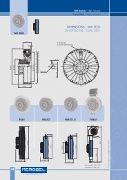
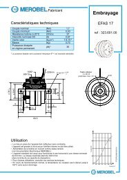
DIMENSIONS - DR, DRD, DRI<br />
ENCOMBREMENT DR, DRD, DRI<br />
4 25 50 30 52 126 125 80 100 48.5 15 15<br />
5 30 60 35 70 139 160 100 125 50.5 16 19<br />
6 35 70 45 90 192 203 125 160 74 22.5 22.5<br />
7 45 80 55 110 221 250 160 200 78 22.5 22.5<br />
8 60 100 70 140 278 315 200 250 97.5 37.5 37.5<br />
Size<br />
Taille<br />
4<br />
5<br />
6<br />
7<br />
8<br />
A<br />
8ØL<br />
F<br />
4ØL<br />
G<br />
H<br />
1<br />
www.redex-andantex.com<br />
3<br />
E<br />
J<br />
K<br />
I<br />
4 x ØU / ØV<br />
ØAj6 B ØCk6 D E F G H I J K ØL ØMj6<br />
N O P Q R S T<br />
ØU ØV W ØXh5<br />
2<br />
D<br />
ØC<br />
M6x10 10<br />
M8x15 10<br />
M10x12 14<br />
M12x18 16<br />
M16x24 22<br />
Weight<br />
Poids (kg)<br />
20 72 142 80 124 50 53 M6x6 48 97 30 10<br />
20 80 170 100 155 62.5 67 M6x8 52 120 35 17.5<br />
28 110 222 125 200 80 85 M6x10 70 155 47 39<br />
30 130 280 160 240 100 103 M8x12 90 195 52 70<br />
44 170 358 200 296 125 135 M10x18 110 244 72 130<br />
DRD, DRI : see the lever dimensions p 38<br />
DRD, DRI : voir les dimensions des leviers de commande p 38<br />
Output mounting flange option + shafts end details : see page 112<br />
Option flasque-bride côté sortie + détails des bouts d’arbres : voir page 112<br />
111
SHAFT ENDS & OPTIONAL FLANGES<br />
BOUTS D’ARBRES & OPTIONS FLASQUES BRIDES<br />
SHAFT ENDS<br />
BOUTS D’ARBRES<br />
on<br />
4 x H ØE<br />
sur<br />
on<br />
3 x H<br />
sur<br />
ØE<br />
112<br />
Key<br />
Clavette<br />
Tapped holes<br />
Trous taraudés<br />
OPTIONAL FLANGE C<br />
OPTION FLASQUE C<br />
120°<br />
45°<br />
90°<br />
OPTIONAL FLANGE D<br />
OPTION FLASQUE D<br />
www.redex-andantex.com<br />
3<br />
F<br />
3<br />
D<br />
G +0<br />
-0.1<br />
2<br />
ØC<br />
ØA<br />
ØB<br />
F D<br />
G +0<br />
-0.1<br />
A<br />
2<br />
ØC<br />
ØB<br />
Size<br />
Taille<br />
a N9 D - 5<br />
Ø 8 10 14 15 16 17 20 22 25 30 32 35 40 45 50 55 60<br />
a 2 3 5 5 5 5 6 6 8 8 10 10 12 14 40 16 18<br />
b 2 3 5 5 5 5 6 6 7 7 8 8 8 9 9 10 11<br />
k 9 11.4 16.3 17.3 18.3 19.3 22.8 24.8 28.3 33.3 35.3 38.3 43.3 48.3 53.8 59 64.4<br />
m M3 M4 M5 M5 M6 M5 M6 M8 M8 M8 M8 M10 M12 M12 M12 M16 M16<br />
L2 4.5 6 10 10 10 10 10 19 15 15 15 19 24 24 24 29 29<br />
Ø D1<br />
4 x<br />
Øm x l2<br />
D SERIES - Differential Phase Shifters<br />
SERIE D - Différentiels Positionneurs<br />
l1<br />
ØD h5<br />
b<br />
+0<br />
-0.2<br />
K<br />
A Bg6 Ck6 D E F G H<br />
L2<br />
Ø m<br />
Ø<br />
4 70 80 30 52 120 48.5 3 M6x12<br />
5 90 105 35 70 155 50.5 3 M8x15<br />
6 112 130 45 90 195 74 3 M10x20<br />
7 155 175 55 110 235 78 3 M12x20<br />
8 190 220 70 140 300 97.5 3 M16x24<br />
Size<br />
Taille<br />
Size<br />
Taille<br />
D l1 m x l2 D1<br />
4 30 1.5 M6x8 48<br />
5 35 2.5 M6x8 52<br />
6 47 2.5 M6x10 70<br />
7 52 2.5 M8x15 90<br />
8 72 3 M10x18 110<br />
A Bg6 Ck6 D E F G H<br />
4 21.75 115 30 52 145 48.5 3 9<br />
5 21.5 145 35 70 170 50.5 3 11<br />
6 37 180 45 90 220 74 3 13<br />
7 35.75 230 55 110 280 78 3 16<br />
8 42.5 290 70 140 350 97.5 3 22<br />
All data subject to change without notice<br />
Données susceptibles d’être modifiées sans préavis
D Series Série D<br />
D SERIES - Differential Phase Shifters<br />
SERIE D - Différentiels Positionneurs<br />
LUBRICATION<br />
LUBRIFICATION<br />
All units are provided for splash lubrication, but are not<br />
shipped with oil. Oil with viscosity 150 centistokes at<br />
40°C (ISO V.G. 150) should be used.<br />
- The first oil change is after 200 hours running (bedding<br />
in period).<br />
- Change the oil after every 300 hours and check the<br />
level every month.<br />
MOUNTING POSITION<br />
POSITION DE MONTAGE<br />
DLO & DLO-D Series<br />
Série DLO & DLO-D<br />
1<br />
3<br />
H1<br />
2<br />
Fill / Remplissage<br />
Level / Niveau<br />
Drain / Vidange<br />
DR, DRD, DRI Series<br />
Série DR, DRD, DRI<br />
1<br />
H1<br />
3<br />
Fill / Remplissage<br />
Level / Niveau<br />
Drain / Vidange<br />
2<br />
1<br />
1<br />
3<br />
H2<br />
H2<br />
3<br />
2<br />
2<br />
3<br />
www.redex-andantex.com<br />
LUBRICATION<br />
LUBRIFICATION<br />
Les positionneurs à différentiels REDEX sont livrés sans<br />
huile. Le remplissage, le contrôle et la vidange s’effectuent<br />
par les orifices indiqués ci-dessous. Utiliser une<br />
huile 150 cst à 40°C (ISO V.G. 150).<br />
- Première vidange après 200 heures de fonctionnement<br />
(période de rodage).<br />
- Vidange toutes les 300 heures et vérification du<br />
niveau tous les mois.<br />
1<br />
H3<br />
1<br />
H3<br />
3<br />
2<br />
1<br />
1<br />
H4<br />
3<br />
3<br />
H4<br />
2<br />
113
NOTES<br />
NOTES<br />
114<br />
www.redex-andantex.com
www.redex-andantex.com<br />
NOTES<br />
NOTES<br />
115