MCW-D 200 - Beyerdynamic
MCW-D 200 - Beyerdynamic
MCW-D 200 - Beyerdynamic

You also want an ePaper? Increase the reach of your titles
YUMPU automatically turns print PDFs into web optimized ePapers that Google loves.
BEDIENUNGSANLEITUNG<br />
OPERATING INSTRUCTIONS<br />
NOTICE D’UTILISATION<br />
<strong>MCW</strong>-D <strong>200</strong><br />
Version 4.0<br />
Digitales, drahtloses Diskussionssystem<br />
Digital, wireless Discussion System<br />
Système de conférence digital sans fil
Hinweis<br />
Diese Bedienungsanleitung wendet sich an technisch qualifiziertes Personal, das speziell auf dem Gebiet der Elektrotechnik ausgebildet ist.<br />
Die Kenntnis und das technisch einwandfreie Umsetzen der in dieser Bedienungsanleitung enthaltenen Hinweise sind Voraussetzung für eine<br />
problemlose Installation und Inbetriebnahme sowie für die Sicherheit beim Betrieb der beschriebenen Produkte.<br />
In dieser Anleitung wird nicht jeder denkbare Fall der Installation, des Betriebs oder der Instandhaltung behandelt. Für weitere Informationen<br />
steht Ihnen Ihr beyerdynamic-Händler oder beyerdynamic GmbH & Co.KG zur Verfügung.<br />
beyerdynamic GmbH & Co. KG übernimmt keine Haftung für in dieser Dokumentation enthaltene Fehler sowie für beiläufige oder<br />
Folgeschäden im Zusammenhang mit der Bereitstellung, Darstellung oder Verwendung dieser Dokumentation und der darin beschriebenen<br />
Programme oder Produkte.<br />
Hinweise für eventuelle Rücksendungen<br />
1. Um Beschädigungen zu vermeiden, versenden Sie die Sprechstellen vorzugsweise im Ladekoffer.<br />
2. Falls einzelne Sprechstellen versendet werden sollen, verpacken Sie diese bitte so, dass keine schweren Gegenstände auf die<br />
Schwanenhälse drücken können.
<strong>MCW</strong>-D <strong>200</strong> – Inhalt 3<br />
1. Allgemeine Sicherheitshinweise . . . . . . . . . . . . . . . . . . . . . . . . . . . . . . . . . . . . . . . . . . . . . . . . . . . . . . . . Seite 4<br />
2. Aufstellung . . . . . . . . . . . . . . . . . . . . . . . . . . . . . . . . . . . . . . . . . . . . . . . . . . . . . . . . . . . . . . . . . . . . . . . Seite 6<br />
3. Steuerzentrale <strong>MCW</strong>-D <strong>200</strong>. . . . . . . . . . . . . . . . . . . . . . . . . . . . . . . . . . . . . . . . . . . . . . . . . . . . . . . . . . . Seite 6<br />
3.1 Bedien- und Kontrollelemente . . . . . . . . . . . . . . . . . . . . . . . . . . . . . . . . . . . . . . . . . . . . . . . . . . Seite 6<br />
3.2 Inbetriebnahme . . . . . . . . . . . . . . . . . . . . . . . . . . . . . . . . . . . . . . . . . . . . . . . . . . . . . . . . . . . . . Seite 7<br />
3.2.1 Aufstellen der Steuerzentrale . . . . . . . . . . . . . . . . . . . . . . . . . . . . . . . . . . . . . . . . . . . . . Seite 7<br />
3.2.2 Antennen anschließen . . . . . . . . . . . . . . . . . . . . . . . . . . . . . . . . . . . . . . . . . . . . . . . . . . Seite 7<br />
3.2.3 Audioanschluss. . . . . . . . . . . . . . . . . . . . . . . . . . . . . . . . . . . . . . . . . . . . . . . . . . . . . . . . Seite 8<br />
3.2.4 Netzanschluss . . . . . . . . . . . . . . . . . . . . . . . . . . . . . . . . . . . . . . . . . . . . . . . . . . . . . . . . . Seite 8<br />
3.2.5 Ein-/Ausschalten . . . . . . . . . . . . . . . . . . . . . . . . . . . . . . . . . . . . . . . . . . . . . . . . . . . . . . . Seite 8<br />
3.2.6 Kanal-Anzeige . . . . . . . . . . . . . . . . . . . . . . . . . . . . . . . . . . . . . . . . . . . . . . . . . . . . . . . . Seite 9<br />
3.2.7 Rackmontage . . . . . . . . . . . . . . . . . . . . . . . . . . . . . . . . . . . . . . . . . . . . . . . . . . . . . . . . . Seite 9<br />
3.2.8 Anschluss von Mediensteuersystem und PC . . . . . . . . . . . . . . . . . . . . . . . . . . . . . . . . . . Seite 9<br />
3.3 Anschließen abgesetzter Antennen . . . . . . . . . . . . . . . . . . . . . . . . . . . . . . . . . . . . . . . . . . . . . . Seite 10<br />
3.4 Fernspeisung der Antennensignalverstärker über Zentrale . . . . . . . . . . . . . . . . . . . . . . . . . . . . . Seite 11<br />
4. Optionaler Einbau von Nachrüstplatinen für weitere Funktionen . . . . . . . . . . . . . . . . . . . . . . . . . . . . . . . Seite 12<br />
4.1 Zusätzliche Sende-/Empfangskanäle . . . . . . . . . . . . . . . . . . . . . . . . . . . . . . . . . . . . . . . . . . . . . . Seite 12<br />
4.2 Fremdsprachige Konferenzen / Dolmetschanwendungen . . . . . . . . . . . . . . . . . . . . . . . . . . . . . . Seite 15<br />
4.3 Digitale Ein- und Ausgänge AES/EBU und S-PDIF . . . . . . . . . . . . . . . . . . . . . . . . . . . . . . . . . . . . Seite 15<br />
5. Delegierten- und Präsidentensprechstellen . . . . . . . . . . . . . . . . . . . . . . . . . . . . . . . . . . . . . . . . . . . . . . . . Seite 16<br />
5.1 Sprechstellen <strong>MCW</strong>-D 2011/2013 und <strong>MCW</strong>-D 2021/2023 . . . . . . . . . . . . . . . . . . . . . . . . . . . . Seite 16<br />
5.1.1 Bedien- und Kontrollelemente . . . . . . . . . . . . . . . . . . . . . . . . . . . . . . . . . . . . . . . . . . . . Seite 16<br />
5.1.2 Ein-/Ausschalten . . . . . . . . . . . . . . . . . . . . . . . . . . . . . . . . . . . . . . . . . . . . . . . . . . . . . . . Seite 17<br />
5.1.3 DC-gespeiste Versionen <strong>MCW</strong>-D 2021 DC und <strong>MCW</strong>-D 2023 DC . . . . . . . . . . . . . . . . . Seite 17<br />
5.2 Sprechstellen <strong>MCW</strong>-D 2071 und 2073 mit Display. . . . . . . . . . . . . . . . . . . . . . . . . . . . . . . . . . . Seite 18<br />
5.2.1 Bedien- und Kontrollelemente . . . . . . . . . . . . . . . . . . . . . . . . . . . . . . . . . . . . . . . . . . . . Seite 18<br />
5.2.2 Ein-/Ausschalten . . . . . . . . . . . . . . . . . . . . . . . . . . . . . . . . . . . . . . . . . . . . . . . . . . . . . . . Seite 19<br />
5.2.3 DC-gespeiste Versionen <strong>MCW</strong>-D 2071 DC und <strong>MCW</strong>-D 2073 DC . . . . . . . . . . . . . . . . . Seite 19<br />
5.2.4 Einstellbare Funktionen <strong>MCW</strong>-D 2071 und <strong>MCW</strong>-D 2073 . . . . . . . . . . . . . . . . . . . . . . . Seite 20<br />
5.3 Systemanschlusseinheit <strong>MCW</strong>-D 2673 . . . . . . . . . . . . . . . . . . . . . . . . . . . . . . . . . . . . . . . . . . . . Seite 22<br />
5.3.1 Anschlüsse . . . . . . . . . . . . . . . . . . . . . . . . . . . . . . . . . . . . . . . . . . . . . . . . . . . . . . . . . . . Seite 22<br />
5.3.2 Installation . . . . . . . . . . . . . . . . . . . . . . . . . . . . . . . . . . . . . . . . . . . . . . . . . . . . . . . . . . . Seite 22<br />
5.3.3 Ein-/Ausschalten . . . . . . . . . . . . . . . . . . . . . . . . . . . . . . . . . . . . . . . . . . . . . . . . . . . . . . . Seite 22<br />
5.3.4 Systemanschlusseinheit mit Display . . . . . . . . . . . . . . . . . . . . . . . . . . . . . . . . . . . . . . . . . Seite 22<br />
5.4 Speisung/Betriebszeit . . . . . . . . . . . . . . . . . . . . . . . . . . . . . . . . . . . . . . . . . . . . . . . . . . . . . . . . . Seite 23<br />
5.5 Speisung über externes Netzteil CA 2455 . . . . . . . . . . . . . . . . . . . . . . . . . . . . . . . . . . . . . . . . . Seite 23<br />
5.6 Speisung <strong>MCW</strong>-D 2673 . . . . . . . . . . . . . . . . . . . . . . . . . . . . . . . . . . . . . . . . . . . . . . . . . . . . . . . Seite 23<br />
5.7 Betriebsart Manuell . . . . . . . . . . . . . . . . . . . . . . . . . . . . . . . . . . . . . . . . . . . . . . . . . . . . . . . . . . Seite 24<br />
5.8 Anmeldebetrieb ohne externen PC oder Steuerung . . . . . . . . . . . . . . . . . . . . . . . . . . . . . . . . . . Seite 24<br />
5.9 Aufzeichnen der Konferenz . . . . . . . . . . . . . . . . . . . . . . . . . . . . . . . . . . . . . . . . . . . . . . . . . . . . Seite 25<br />
5.10 Pflege der <strong>MCW</strong>-D Sprechstellen . . . . . . . . . . . . . . . . . . . . . . . . . . . . . . . . . . . . . . . . . . . . . . . . Seite 25<br />
5.11 Wiederaufladbare Batterien / Akkus . . . . . . . . . . . . . . . . . . . . . . . . . . . . . . . . . . . . . . . . . . . . . . Seite 25<br />
6. Programmierbare Sprechstellenfunktionen mit <strong>MCW</strong>-D <strong>200</strong> Editor Software . . . . . . . . . . . . . . . . . . . . . . Seite 26<br />
6.1 Sicherheitscode . . . . . . . . . . . . . . . . . . . . . . . . . . . . . . . . . . . . . . . . . . . . . . . . . . . . . . . . . . . . . Seite 26<br />
6.2 Auto-Off-Funktion . . . . . . . . . . . . . . . . . . . . . . . . . . . . . . . . . . . . . . . . . . . . . . . . . . . . . . . . . . . Seite 26<br />
6.3 Programmierbare Funktionstaste Präsident . . . . . . . . . . . . . . . . . . . . . . . . . . . . . . . . . . . . . . . . . Seite 26<br />
6.4 Abstimmung . . . . . . . . . . . . . . . . . . . . . . . . . . . . . . . . . . . . . . . . . . . . . . . . . . . . . . . . . . . . . . . Seite 27<br />
6.5 Override-Betrieb. . . . . . . . . . . . . . . . . . . . . . . . . . . . . . . . . . . . . . . . . . . . . . . . . . . . . . . . . . . . . Seite 27<br />
6.6 Push-To-Talk-Betrieb . . . . . . . . . . . . . . . . . . . . . . . . . . . . . . . . . . . . . . . . . . . . . . . . . . . . . . . . . . Seite 27<br />
6.7 Automatik-Betrieb . . . . . . . . . . . . . . . . . . . . . . . . . . . . . . . . . . . . . . . . . . . . . . . . . . . . . . . . . . . Seite 27<br />
6.8 Betriebsart Anmeldung . . . . . . . . . . . . . . . . . . . . . . . . . . . . . . . . . . . . . . . . . . . . . . . . . . . . . . . Seite 28<br />
6.9 Zoning-Funktion. . . . . . . . . . . . . . . . . . . . . . . . . . . . . . . . . . . . . . . . . . . . . . . . . . . . . . . . . . . . . Seite 28<br />
6.10 Empfangen von Nachrichten . . . . . . . . . . . . . . . . . . . . . . . . . . . . . . . . . . . . . . . . . . . . . . . . . . . Seite 28<br />
7. Ladegerät LE-D 10 im Koffer <strong>MCW</strong>-D 10. . . . . . . . . . . . . . . . . . . . . . . . . . . . . . . . . . . . . . . . . . . . . . . . . Seite 29<br />
7.1 Inbetriebnahme . . . . . . . . . . . . . . . . . . . . . . . . . . . . . . . . . . . . . . . . . . . . . . . . . . . . . . . . . . . . . Seite 29<br />
7.2 Ladevorgang . . . . . . . . . . . . . . . . . . . . . . . . . . . . . . . . . . . . . . . . . . . . . . . . . . . . . . . . . . . . . . . Seite 30<br />
7.3 Formierung . . . . . . . . . . . . . . . . . . . . . . . . . . . . . . . . . . . . . . . . . . . . . . . . . . . . . . . . . . . . . . . . Seite 30<br />
8. Akkuladung über externes Ladegerät CA 2456 . . . . . . . . . . . . . . . . . . . . . . . . . . . . . . . . . . . . . . . . . . . . Seite 31<br />
9. Problemlösung. . . . . . . . . . . . . . . . . . . . . . . . . . . . . . . . . . . . . . . . . . . . . . . . . . . . . . . . . . . . . . . . . . . . . Seite 32<br />
10. Komponenten . . . . . . . . . . . . . . . . . . . . . . . . . . . . . . . . . . . . . . . . . . . . . . . . . . . . . . . . . . . . . . . . . . . . . Seite 34<br />
11. Zubehör. . . . . . . . . . . . . . . . . . . . . . . . . . . . . . . . . . . . . . . . . . . . . . . . . . . . . . . . . . . . . . . . . . . . . . . . . . Seite 34<br />
12. Technische Daten. . . . . . . . . . . . . . . . . . . . . . . . . . . . . . . . . . . . . . . . . . . . . . . . . . . . . . . . . . . . . . . . . . . Seite 35<br />
13. Blockschaltbild Audio-Signalfluss . . . . . . . . . . . . . . . . . . . . . . . . . . . . . . . . . . . . . . . . . . . . . . . . . . . . . . . Seite 39<br />
Konformitätserklärung . . . . . . . . . . . . . . . . . . . . . . . . . . . . . . . . . . . . . . . . . . . . . . . . . . . . . . . . . . . . . . . . . . . Seite 116<br />
deutsch
<strong>MCW</strong>-D <strong>200</strong> – Sicherheitshinweise 4<br />
Sie haben sich für das drahtlose, digitale Konferenzsystem <strong>MCW</strong>-D <strong>200</strong> von beyerdynamic entschieden. Wir danken für Ihr Vertrauen. Nehmen<br />
Sie sich bitte einige Minuten Zeit und lesen Sie diese Bedienungsanleitung vor Inbetriebnahme aufmerksam durch.<br />
In dieser Bedienungsanleitung werden die Installation und Bedienung des Systems ohne Steuerung und Konfiguration über einen PC beschrieben.<br />
Folgende Komponenten gehören zur Grundausstattung eines Systems für den Betrieb ohne PC:<br />
Steuerzentrale <strong>MCW</strong>-D <strong>200</strong><br />
Delegiertensprechstelle <strong>MCW</strong>-D 2011, 2021 oder 2071<br />
Präsidentensprechstelle <strong>MCW</strong>-D 2013, 2023 oder 2073<br />
Systemanschlusseinheit <strong>MCW</strong>-D 2673<br />
Weitere Informationen zur Steuerung und Konfiguration des <strong>MCW</strong>-D <strong>200</strong> Systems über einen PC finden Sie in der Bedienungs anleitung<br />
<strong>MCW</strong>-D <strong>200</strong> Editor.<br />
Wichtig:<br />
Die Komponenten des <strong>MCW</strong>-Digital Systems sind in Europa gemäß Richtlinie R&TTE 99/5/EEC unter der Kennzeichnung CE 0682 !<br />
zugelassen.<br />
Zusätzlich besteht eine Zulassung gemäß der USA-Norm FCC.<br />
1. Allgemeine Sicherheitshinweise<br />
Steuerzentrale und Ladegerät<br />
Allgemein<br />
LESEN Sie die Bedienungsanleitung.<br />
BEWAHREN Sie diese Bedienungsanleitung auf.<br />
BEFOLGEN Sie die aufgeführten Bedienungs- und Sicherheitshinweise.<br />
Haftungsausschluss<br />
Die Firma beyerdynamic GmbH & Co. KG übernimmt keine Haftung für Schäden am Produkt oder Verletzungen von Personen aufgrund<br />
unachtsamer, unsachgemäßer, falscher oder nicht dem vom Hersteller angegebenen Zweck entsprechender Verwendung des Produkts.<br />
Standort<br />
Das Gerät muss so aufgestellt werden, dass der Netzanschluss, Netzschalter und alle Anschlüsse auf der Rückseite des Gerätes leicht<br />
zugänglich sind.<br />
Wenn Sie das Gerät an einen anderen Ort transportieren, achten Sie darauf, dass es ausreichend gesichert ist und niemand durch ein<br />
eventuelles Herunterfallen oder Stoßen am Gerät verletzt werden kann.<br />
Brandschutz<br />
Stellen Sie niemals offene Brandquellen (z.B. Kerzen) auf das Gerät.<br />
Feuchtigkeit / Wärmequellen<br />
Setzen Sie das Gerät niemals Regen oder hoher Feuchtigkeit aus. Installieren Sie es daher nicht in unmittelbarer Nähe von Swimming Pools,<br />
Duschanlagen, feuchten Kellerräumen oder sonstigen Bereichen mit außergewöhnlich hoher Luftfeuchtigkeit.<br />
Stellen Sie niemals mit Flüssigkeiten gefüllte Gegenstände (z.B. Vasen oder Trinkgläser) auf das Gerät. Flüssigkeiten in den Geräten<br />
können einen Kurzschluss verursachen.<br />
Installieren und betreiben Sie das Gerät auch niemals in unmittelbarer Nähe von Heizkörpern, Beleuchtungsanlagen oder anderen<br />
wärmeerzeugenden Geräten.<br />
Ventilation<br />
Dieses Gerät benötigt eine ausreichende Ventilation. Decken Sie die Lüftungsöffnungen nicht ab. Wenn die Eigenwärme nicht abgeführt<br />
wird, kann das Gerät beschädigt oder brennbare Materialien in unmittelbarer Nähe können entzündet werden. Achten Sie daher darauf,<br />
dass die Luft durch die Lüftungsöffnungen frei zirkulieren kann und halten Sie brennbare Materialien fern.<br />
Stecken Sie keine Gegenstände in die Lüftungs- und andere Öffnungen. Sie könnten das Gerät beschädigen und/oder sich verletzen.<br />
Anschluss<br />
Das Gerät muss an eine Netz-Steckdose mit Schutzkontakt angeschlossen werden.<br />
Verlegen Sie alle Kabel stets so, dass sie nicht durch scharfe Gegenstände geknickt oder gar durchgetrennt werden können.<br />
Verlegen Sie alle Anschlusskabel so, dass niemand darüber stolpern und sich verletzen kann.<br />
Schalten Sie bei allen Arbeiten an den Ein- und Ausgängen die Stromzufuhr aus.<br />
Überprüfen Sie, ob die Anschlusswerte mit der vorhandenen Netzstromversorgung über einstimmen. Bei Anschluss des Systems an<br />
die falsche Stromversorgung können ernsthafte Schäden entstehen. Eine falsche Netzspannung kann das Gerät beschädigen oder einen<br />
elektrischen Schlag verursachen.<br />
Nehmen Sie das Gerät bei einem Gewitter oder wenn Sie es längere Zeit nicht benutzen, vom Netz.<br />
Wenn durch das Gerät eine Sicherung defekt oder ein Kurzschluss verursacht wurde, nehmen Sie es vom Netz und lassen Sie es<br />
überprüfen und reparieren.<br />
Fassen Sie das Netzkabel nicht mit nassen Händen an. An den Kontaktstiften sollte sich kein Wasser oder Staub befinden. In beiden Fällen<br />
könnten Sie einen elektrischen Schlag erleiden.<br />
Das Netzkabel muss fest angeschlossen sein. Ist es lose, besteht Brandgefahr.<br />
Ziehen Sie das Netzkabel immer am Stecker vom Netz und/oder vom Gerät - niemals am Kabel. Das Kabel könnte beschädigt werden und<br />
einen elektrischen Schlag oder Brand verursachen.<br />
Wenn das Netzkabel angeschlossen ist, bringen Sie das Gerät nicht mit anderen metallischen Gegenständen in Berührung.<br />
Setzen Sie das Gerät nicht ein, wenn der Netzstecker beschädigt ist.<br />
Wenn Sie defektes oder ungeeignetes Zubehör anschließen, kann das Gerät beschädigt werden. Verwenden Sie daher nur die von<br />
beyerdynamic lieferbaren oder empfohlenen Anschlusskabel. Verwenden Sie selbstkonfektionierte Kabel, erlischt Ihr Garantieanspruch.
<strong>MCW</strong>-D <strong>200</strong> – Sicherheitshinweise 5<br />
Wird das Gerät in ein 19"-Rack eingebaut, achten Sie darauf dass der Netzanschluss, Netzschalter und alle Audioanschlüsse auf der<br />
Rückseite des Gerätes leicht zugänglich sind.<br />
Reinigung<br />
Reinigen Sie das Gerät nur mit einem leicht feuchtem oder trockenem Tuch. Verwenden Sie niemals Lösungsmittel, da diese die Oberfläche<br />
beschädigen.<br />
Fehlerbeseitigung / Reparatur<br />
Öffnen Sie nicht eigenmächtig das Gerät. Sie könnten einen elektrischen Schlag erleiden.<br />
Überlassen Sie alle Servicearbeiten nur autorisiertem Fachpersonal.<br />
Ladegerät<br />
Verwenden Sie zum Laden der in den Sprechstellen integrierten Akkus das Ladegerät LE-D 10 bzw. das externe Ladegerät CA 2456.<br />
Entfernen Sie auf keinen Fall den Schaumstoff aus dem Ladegerät LE-D 10. Im Innern des Ladegerätes befinden sich keine wartungsfähigen<br />
Teile.<br />
Das Ladegerät wurde zur Ladung der Akkus in den <strong>MCW</strong>-D 2xxx Sprechstellen ausgelegt. Laden Sie daher nur <strong>MCW</strong>-D 2xxx Sprechstellen<br />
und keine anderen akku- oder batteriebetriebenen Geräte auf. Die Akkus oder Batterien könnten explodieren und Sie<br />
verletzen bzw. das Gerät beschädigen.<br />
Wenn Sie das Ladegerät mit Zubehör verwenden, das nicht für dieses entwickelt wurde, kann dies einen Brand, elektrischen Schlag oder<br />
eine Körperverletzung zur Folge haben.<br />
Versuchen Sie niemals das Ladegerät selbst zu reparieren. Es besteht die Gefahr, einen elektrischen Schlag zu erleiden oder einen Brand<br />
auszulösen.<br />
Setzen Sie das Ladegerät niemals als Netz- oder Speiseteil für elektrische Geräte ein.<br />
Sprechstellen<br />
Aufbau<br />
Sprechstellen mit einem Metallgehäuse sind schwer. Platzieren Sie diese Sprechstellen daher immer so, dass sie nicht herunterfallen<br />
können. Sie könnten sich oder andere verletzen bzw. die Sprechstelle beschädigen.<br />
Zum Ausrichten des Schwanenhalsmikrofons der Sprechstelle und zum Vermeiden einer Überdehnung und frühzeitigen<br />
Verschleißerscheinungen, fassen Sie das Mikrofon immer am unteren flexiblen Teilstück an, niemals oben am Mikrofonkopf<br />
oder am starren Rohr. Der Schwanenhals darf nur bis max. 90 Grad gebogen werden.<br />
Verletzungsgefahr<br />
Verfügt die Sprechstelle über ein Schwanenhalsmikrofon, passen Sie auf, dass Sie sich an diesem nicht verletzen, z.B. ins Auge bohren.<br />
Die Ladekontakte der <strong>MCW</strong>-D 2xxx Sprechstellen können Sachbeschädigungen, Verletzungen oder Brandschäden verursachen, wenn die<br />
Kontakte mit leitenden Materialien wie Schmuck, Schlüsseln oder Ketten in Berührung kommen. Dies kann zu einem geschlossenen<br />
Stromkreis und dadurch zur Erhitzung des Materials führen. Um einen solchen ungewollten Stromkreis zu vermeiden, müssen die<br />
Ladekontakte mit Vorsicht behandelt werden. Dies gilt insbesondere dann, wenn die Sprechstellen in einer Tasche oder einem anderen<br />
Behälter zusammen mit metallischen Gegenständen transportiert werden.<br />
Laden / Akkus<br />
Wenn Sie die Sprechstellen im Ladegerät aufladen, achten Sie darauf, dass Sie sich beim Einsetzen oder Herausnehmen der Sprechstellen<br />
nicht verletzen.<br />
Schalten Sie das Ladegerät erst ein, nachdem Sie alle Sprechstellen eingesetzt haben. Leere Ladefächer sollten Sie während des<br />
Ladevorgangs auf keinen Fall berühren. Sie könnten einen elektrischen Schlag erleiden.<br />
Vermeiden Sie eine Tiefentladung der Sprechstellenakkus. Die Akkus könnten beschädigt werden und die Lebensdauer der Batterien kann<br />
sich verkürzen.<br />
Wenn akku- oder batteriebetriebene Geräte längere Zeit nicht eingesetzt werden (z.B. 1 Jahr), kann sich die Selbstentladung der<br />
Batterie/Akku beschleunigen. Die Temperatur bei einer Langzeitaufbewahrung sollte zwischen +10°C und +30°C betragen.<br />
Setzen Sie die Sprechstellen mehrere Monate nicht ein, sollten Sie die Akkus in den Sprechstellen mindestens zweimal pro Jahr aufladen,<br />
um ein Auslaufen sowie eine Verschlechterung in der Leistung durch Selbstentladung verhindern.<br />
Lautstärke<br />
Verwenden die Konferenzteilnehmer mit den <strong>MCW</strong>-D 2xxx Sprechstellen einen Kopfhörer, achten Sie darauf, dass die<br />
Lautstärke über die <strong>MCW</strong>-D <strong>200</strong> Editor Software nicht zu hoch eingestellt ist. Das Gehör der Konferenz teilnehmer könnte<br />
sonst dauerhaft geschädigt werden.<br />
Sicherheitssymbole<br />
Der nebenstehende Aufkleber ist auf der Geräterückseite angebracht.<br />
Die Symbole haben folgende Bedeutung:<br />
Dieses Symbol zeigt an, dass gefährliche Spannungswerte, die ein Stromschlagrisiko darstellen,<br />
innerhalb des Gerätes auftreten.<br />
Dieses Symbol zeigt an, dass die diesem Gerät beiliegende Bedienungsanleitung wichtige<br />
Betriebs- und Wartungsanweisungen enthält.<br />
deutsch
<strong>MCW</strong>-D <strong>200</strong> – Steuerzentrale 6<br />
2. Aufstellung<br />
Die Steuerzentrale <strong>MCW</strong>-D <strong>200</strong> ist zur Aufstellung auf einen Tisch bzw. zum Einbau in ein 19"-Rack vorgesehen. Bei der Aufstellung müssen<br />
Sie die Sicherheitsinformationen in Kapitel 1 beachten.<br />
Insbesondere und darüber hinaus<br />
darf die Umgebungstemperatur am Aufstellungsort 40°C nicht überschreiten.<br />
darf der Aufstellungsort keiner übermäßigen Staub- und Feuchtigkeitsentwicklung ausgesetzt sein.<br />
sollte das Gerät keiner direkten Sonneneinstrahlung ausgesetzt sein.<br />
müssen die Anschlüsse vor direktem Zugriff während des Betriebes geschützt sein.<br />
müssen die Zuleitungen gegebenenfalls durch extern anzubringende Vorrichtungen zugentlastet werden.<br />
muss der Aufstellungsort vor Vibrationen geschützt sein.<br />
3. Steuerzentrale <strong>MCW</strong>-D <strong>200</strong><br />
Die Steuerzentrale <strong>MCW</strong>-D <strong>200</strong> ist das Herzstück des Systems. Mit ihr werden die Delegierten- und Präsidenten sprech stellen gesteuert.<br />
Mit den entsprechenden Erweiterungskarten stellt sie weitere Sende- und Empfangskanäle zur Verfügung oder ermöglicht Dolmetsch -<br />
anwendungen.<br />
3.1 Bedien- und Kontrollelemente<br />
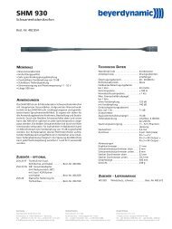
Vorderseite<br />
(1) (2) (3) (4)<br />
(1) Power-LED. LED leuchtet grün: Gerät ist eingeschaltet und betriebsbereit.<br />
(2) Stand-By-Taster. Bei längerem Drücken (> 3 Sekunden) werden alle eingeschalteten Sprechstellen im Empfangsbereich abgeschaltet. Bei<br />
kurzem Drücken werden alle zugeteilten Mikrofone abgeschaltet.<br />
(3) Reset, setzt die Anlage in den Einschaltzustand zurück. (Versenkter Taster, z.B. mit Büroklammer bedienen.)<br />
(4) LEDs für Status der Empfangskanäle. LED leuchtet grün: Kanal frei. LED leuchtet rot: Kanal belegt.<br />
Standardeinstellung: Kanal „Data“ für Datenkommunikation. Kanal 1 - 4 für Sprechstellen, Kanäle 5 - 7 nicht bestückt.<br />
Hinweis:<br />
Die „Data“-LED leuchtet kurz rot auf, wenn eine Delegiertensprechstelle einen gültigen Befehl sendet, z.B. wenn die Batteriespannung<br />
unter die vorgegebene Schwelle sinkt, sendet die Sprechstelle ca. einmal pro Minute eine Nachricht auf dem Datenkanal.<br />
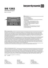
Rückseite<br />
(6)<br />
(19)<br />
(19)<br />
(5)<br />
(19)<br />
(18)<br />
(17)<br />
(16)<br />
(15)<br />
(14)<br />
(13) (12)<br />
(11)<br />
(10)<br />
(9)<br />
(7)<br />
(8)<br />
(6)
<strong>MCW</strong>-D <strong>200</strong> – Steuerzentrale 7<br />
(5) LAN-Netzwerkanschluss (RJ 45 Steckverbinder) IPX bzw. TCP/IP<br />
(6) Anschluss für Empfangsantenne A/B (N-Steckverbinder)<br />
(7) Netzsicherung<br />
(8) Ein/Ausschalter<br />
(9) Netzanschluss<br />
(10) Master Out - Summenausgang, 3-pol. XLR male, symmetrisch, zum Anschluss externer Geräte wie z.B. Mischpult oder Beschal lungs -<br />
anlage (+6 dBm)<br />
(11) Aux 1 Input - Eingang, 3-pol. XLR female, symmetrisch, zum Anschluss externer Signalquellen<br />
(12) Anschluss für Sendeantenne (N-Steckverbinder)<br />
(13) Pegelsteller für Master Out - Summenausgang, Cinch<br />
(14) Master Out - Summenausgang, Cinch, unsymmetrisch, zum Anschluss externer Geräten wie z.B. Mischpult, Beschallungs anlage oder<br />
Aufnahmegerät (L + R)<br />
(15) Aux 2 Input - Eingang, Cinch, unsymmetrisch, zum Anschluss externer Geräten wie z.B. CD-Player (L + R)<br />
(16) Pegelsteller für Aux 2 Input, Cinch<br />
(17) Serielle Schnittstelle RS 232 für Anschluss von z.B. PC oder Mediensteuerung (9-pol. Sub-D).<br />
Zum Anschluss ein RS 232 Nullmodem bzw. „Crossover“ Kabel (female - female) verwenden.<br />
Optionale Erweiterungen für weitere Anschlüsse.<br />
(18) CA 2451 - Analoge Einzel-Ein-/Ausgänge (2 x 25 pol. Sub-D-Buchse) für z.B. Simultan-Dolmetscher-Betrieb und für einzelne<br />
Sende-/Empfangssignale. Siehe auch Kapitel 4.1.<br />
(19) CA 2452 - Digitale Ein-/Ausgänge, AES/EBU (XLR) und S/PDIF (Cinch)<br />
3.2 Inbetriebnahme<br />
3.2.1 Aufstellen der Steuerzentrale<br />
Stellen Sie die Steuerzentrale <strong>MCW</strong>-D <strong>200</strong> in dem Raum auf, in dem die Konferenz stattfindet.<br />
Stellen Sie die Steuerzentrale <strong>MCW</strong>-D <strong>200</strong> nicht neben digital gesteuerte Geräte.<br />
3.2.2 Antennen anschließen<br />
Schließen Sie die Empfangsantennen an die Antenneneingänge A und B (6) an.<br />
Für den Stand-Alone-Betrieb empfehlen wir die Stabwinkelantenne CA 2411.<br />
Schließen Sie die gewünschte Sendeantenne an den Antennenausgang (12) an.<br />
Für den Stand-Alone-Betrieb empfehlen wir die Stabwinkelantenne CA 2411.<br />
(6)<br />
(12)<br />
Wichtig:<br />
Antennen und Sprechstellen sollten Sichtkontakt haben, d.h. zwischen der Steuerzentrale <strong>MCW</strong>-D <strong>200</strong> und den<br />
Sprechstellen dürfen keine Hindernisse sein. Bei Sichtverbindung zwischen Steuerzentrale und Sprechstelle sowie den<br />
Stabwinkelantennen beträgt die Reichweite ca. 30 m innerhalb geschlossener Räume. Für die optimale Reichweite spielt auch<br />
die Oberflächenbeschaffenheit des Tisches eine Rolle. Ideal sind Holz- oder Kunststofftische, bei Metalltischen ist unter Umständen<br />
die Abstrahlung und damit die max. erzielbare Reichweite beeinträchtigt.<br />
Bei Sichtkontakt darf ein Mindestabstand von 1 m zwischen Antennen und Sprechstellen nicht unterschritten werden.<br />
(6)<br />
deutsch
<strong>MCW</strong>-D <strong>200</strong> – Steuerzentrale 8<br />
3.2.3 Audioanschluss<br />
Verbinden Sie den Summenausgang XLR (10) oder Cinch (14) der Steuerzentrale <strong>MCW</strong>-D <strong>200</strong> mit dem Eingang eines Mischpultes /<br />
Mischverstärkers.<br />
Achten Sie darauf, dass die Kabel nicht geknickt oder durchtrennt werden können.<br />
3.2.4 Netzanschluss<br />
(14)<br />
Überprüfen Sie, ob die Anschlusswerte mit der vorhandenen Netzstromversorgung übereinstimmen. Bei Anschluss des Systems an die<br />
falsche Stromversorgung können ernsthafte Schäden entstehen.<br />
Achten Sie darauf, dass das Netzkabel nicht geknickt oder durchtrennt werden kann.<br />
Schließen Sie die Steuerzentrale <strong>MCW</strong>-D <strong>200</strong> ans Netz (9) an. Das Netzteil der Steuerzentrale kann sich automatisch auf eine<br />
Wechselspannung zwischen 100 und 240 Volt bei 50 - 60 Hz einstellen.<br />
3.2.5 Ein-/Ausschalten<br />
Schalten Sie die Steuerzentrale <strong>MCW</strong>-D <strong>200</strong> mit dem Ein-/Ausschalter (8) auf der Rückseite ein oder aus.<br />
Während der ersten ca. 15 Sekunden wird die Steuerzentrale <strong>MCW</strong>-D <strong>200</strong> initialisiert und dabei blinkt die Power LED (1) grün. In dieser Zeit<br />
ist kein Betrieb möglich.<br />
Die Power LED (1) auf der Vorderseite leuchtet grün, wenn die Steuerzentrale betriebsbereit ist.<br />
ACHTUNG:<br />
Schalten Sie bei allen Arbeiten an den Ein- und Ausgängen das Gerät immer aus.<br />
Rückseite Vorderseite<br />
(8)<br />
(1)<br />
(10)<br />
(9)
<strong>MCW</strong>-D <strong>200</strong> – Steuerzentrale 9<br />
3.2.6 Kanal-Anzeige<br />
Je nach Bestückung der Steuerzentrale <strong>MCW</strong>-D <strong>200</strong> leuchten 5 oder mehr Kanal-LEDs (4) grün (Standard: 5 Kanäle).<br />
(4)<br />
Wichtig:<br />
Sollten nicht mindestens 5 LEDs leuchten, kann es auch daran liegen, dass einzelne Kanäle mit der <strong>MCW</strong>-D <strong>200</strong> Editor Software<br />
abgeschaltet wurden.<br />
3.2.7 Rackmontage<br />
Bei Montage in ein 19"-Rackgehäuse sollte über und unter der <strong>MCW</strong>-D <strong>200</strong> Steuerzentrale ein Lüftungsfeld von 1 HE montiert<br />
werden.<br />
3.2.8 Anschluss von Mediensteuersystem und PC<br />
Wenn Sie ein Mediensteuersystem und einen PC an der Steuerzentrale <strong>MCW</strong>-D <strong>200</strong> zusammen anschließen wollen, schließen Sie den PC an<br />
den LAN-Netzwerk anschluss (5) und das Mediensteuersystem an den RS 232-Anschluss (17) an.<br />
Für den LAN-Netzwerkanschluss kann sowohl das IPX- als auch das TCP/IP-Protokoll verwendet werden. Ab Werk ist die<br />
<strong>MCW</strong>-D <strong>200</strong> Steuerzentrale für den Betrieb mit TCP/IP konfiguriert. Werkseitig ist die IP-Adresse 192.168.1.102 (Port 1024) eingestellt. Diese<br />
Einstellung können Sie über die mitgelieferte <strong>MCW</strong>-D <strong>200</strong> Editor Software ändern. Siehe hierzu Bedienungsanleitung <strong>MCW</strong>-D <strong>200</strong> Editor<br />
Software.<br />
Für die direkte Verbindung des LAN-Netzwerkanschlusses mit einem PC muss ein „Crossover“-Kabel verwendet werden. Dies gilt sowohl<br />
für IPX als auch TCP/IP.<br />
Wird der LAN-Netzwerkanschluss an ein lokales Netzwerk angeschlossen, muss ein „1:1“-Kabel verwendet werden.<br />
Die IPX- und TCP/IP-Einstellungen sind im Protokoll erläutert.<br />
Wichtig:<br />
Die RS 232-Schnittstelle und der LAN-Netzwerkanschluss können gleichzeitig zum Betrieb zweier verschiedener Softwares mit der<br />
Steuerzentrale <strong>MCW</strong>-D <strong>200</strong> benutzt werden (z.B. <strong>MCW</strong>-D <strong>200</strong> Voting Software und Konferenz- und Aufnahmesoftware steno-s).<br />
Das Auftreten von Störungen kann jedoch nicht ganz ausgeschlossen werden.<br />
(5)<br />
(17)<br />
deutsch
<strong>MCW</strong>-D <strong>200</strong> – Steuerzentrale 10<br />
3.3 Anschließen abgesetzter Antennen<br />
Die Steuerzentrale <strong>MCW</strong>-D <strong>200</strong> kann auch mit abgesetzten Antennen betrieben werden. Als Anschlusskabel dienen dämpfungsarme Kabel<br />
in verschiedenen Längen. Beachten Sie, dass alle drei Antennen abgesetzt montiert werden müssen. Die Sende anten ne sollte zentral und die<br />
beiden Empfangsantennen links und rechts montiert werden. Durch den Einsatz einer gerichteten Antenne (CA 2413, Gewinn ca. 6 dB) kann<br />
die Reichweite verbessert werden.<br />
Je nach Kabeldämpfung sollten Sie ab einer bestimmten Antennenkabellänge Antennenverstärker einsetzen.<br />
Beispiel für variablen Aufbau mit abgesetzten Antennen<br />
Die Planarantenne CA 2413 wird an die Steuerzentrale <strong>MCW</strong>-D <strong>200</strong> angeschlossen und mit dem Montagekit CA 2462 auf einem Stativ<br />
befestigt. Weitere Installationsmöglichkeiten der Antennen finden Sie in unserem “<strong>MCW</strong>-D Design-Guide”.<br />
Wichtig:<br />
Antennen und Sprechstellen sollten Sichtkontakt haben, d.h. zwischen der Steuerzentrale <strong>MCW</strong>-D <strong>200</strong> und den<br />
Sprechstellen dürfen keine Hindernisse sein. Bei Sichtverbindung zwischen Steuerzentrale und Sprechstelle sowie den abgesetzten<br />
Antennen beträgt die Reichweite ca. 30 m innerhalb geschlossener Räume. Für die optimale Reichweite spielt auch die<br />
Oberflächenbeschaffenheit des Tisches eine Rolle. Ideal sind Holz- oder Kunststofftische, bei Metalltischen ist unter Umständen die<br />
Abstrahlung und damit die max. erzielbare Reichweite beeinträchtigt.<br />
Bei Sichtkontakt darf ein Mindestabstand von 1 m zwischen Antennen und Sprechstellen nicht unterschritten werden.<br />
Raumgröße: bis zu 400 m 2 (20 x 20)<br />
Teilnehmerzahl: 30 - 100<br />
Antennenposition: am Rand der Sitzposition der Teilnehmer, möglichst hoch über dem Tischniveau<br />
Ausrichtung: Antennen zu den Teilnehmern hin ausrichten (gewölbte Seite nach vorne)<br />
Kabeltyp<br />
Max. Kabellänge<br />
Min. Biegeradius<br />
Aircell 7<br />
Standard<br />
CA 2420<br />
bis 20 m<br />
= 1 x CA 2422<br />
oder 2 x CA 2421<br />
25 mm<br />
Ecoflex 10<br />
Low Attenuation<br />
CA 2430<br />
bis 40 m<br />
40 mm
<strong>MCW</strong>-D <strong>200</strong> – Steuerzentrale 11<br />
Kabeldämpfung der verschiedenen Kabeltypen bei 2,4 GHz<br />
Kabellänge 100 m 50 m 30 m<br />
RG 58 100 dB 50 dB 30 dB<br />
RG 213 U 49 dB 24 dB 15 dB<br />
Aircell 7, CA 2420 41 dB 20 dB 12 dB<br />
Ecoflex 10, CA 2430 24 dB 12 dB 7 dB<br />
3.4 Fernspeisung der Antennensignalverstärker über Zentrale<br />
Die Antennensignalverstärker können über die Steuerzentrale <strong>MCW</strong>-D <strong>200</strong> ferngespeist werden. Im Innern der Steuerzentrale <strong>MCW</strong>-D <strong>200</strong><br />
befindet sich eine Diagnose-LED, die durch die Lüftungsschlitze auf der Rückseite abgelesen werden kann.<br />
Diese LED leuchtet grün, wenn die Fernspeisespannung an allen Antennenbuchsen 5 V beträgt.<br />
Die LED blinkt rot, wenn an einer Antennenbuchse ein Kurzschluss auftritt. Überprüfen Sie in diesem Fall die Antennen verkabelung.<br />
Die Fernspeisespannung von 5 V dient zur Versorgung der Antennensignalverstärker CA 2441 RT und CA 2441 T.<br />
ungeeignet<br />
nur kurze Kabellänge<br />
mittlere Kabellänge<br />
längere Kabel<br />
Wir empfehlen den Einsatz des Antennenverstärkers CA 2441 ab einer Kabeldämpfung von ca. 12 - 15 dB, d.h. beim Kabel CA 2420 ab einer<br />
Länge von ca. 40 m und bei CA 2430 ab ca. 60 m.<br />
ACHTUNG:<br />
Die Antennensignalverstärker CA 2441 RT und CA 2441 T dürfen nur mit 5 V DC betrieben werden.<br />
Bei Anschluss eines CA 2441 an den TX-Ausgang der <strong>MCW</strong>-D <strong>200</strong> muss ein Anschlusskabel mit mindestens 10 dB Dämpfung<br />
eingesetzt werden.<br />
deutsch
<strong>MCW</strong>-D <strong>200</strong> – Steuerzentrale 12<br />
4. Optionaler Einbau von Nachrüstplatinen für weitere Funktionen<br />
für 1 zusätzlichen<br />
Sende-/Empfangskanal<br />
CA 2450<br />
4.1 Zusätzliche Sende-/Empfangskanäle<br />
für Fremdsprachenbzw.<br />
Dolmetsch -<br />
anwendungen<br />
CA 2451<br />
CA 2452<br />
zum Anschluss an<br />
digitale Signalquellen<br />
wie z.B. digitales<br />
Mischpult<br />
Wenn in Konferenzen mehr als 4 Sprecher (z.B. 3 Delegierte und 1 Präsident oder 2 Delegierte und 2 Präsidenten) gleich zeitig sprechen<br />
sollen, benötigen Sie mehr Empfangskanäle. Hierfür wurde die Nachrüstplatine CA 2450 1 Sende- / 1 Empfangs kanal entwickelt. Mit den<br />
Nachrüstplatinen CA 2450 kann die Steuerzentrale <strong>MCW</strong>-D <strong>200</strong> um bis zu 3 zusätzliche Sende-/Empfangskanäle erweitert werden.<br />
Standardmäßig sind 5 Sende-/Empfangskanäle bestückt. Diese entsprechen 1 Daten-Kommunikationskanal, 4 Sprechkanälen (z.B. 3 Delegiertenund<br />
1 Präsidentensprechstelle können gleichzeitig eingeschaltet werden) und 5 Hörkanälen (Originalton für Sprech stellen laut sprecher und für<br />
4 Fremdsprachenkanäle bei Dolmetscheranwendung). Siehe auch Zeichnung 2.<br />
Im voll bestückten Zustand mit 3 Nachrüstplatinen CA 2450 stellt die Steuerzentrale neben dem Datenkommunikationskanal<br />
7 Sprechkanäle und 8 Hörkanäle zur Verfügung. Sollen die Hörkanäle für den Dolmetscherbetrieb genutzt werden, ist die Nachrüst platine<br />
CA 2451 notwendig (siehe Kapitel 4.2)!<br />
Wichtig:<br />
Bevor Sie den Einbau vornehmen, müssen Sie die <strong>MCW</strong>-D <strong>200</strong> Steuerzentrale vom Stromnetz trennen, d.h. den Netzstecker aus<br />
der Steckdose ziehen.<br />
Vorkehrungen zum ESD-Schutz<br />
Elektronische Bauelemente sind bei elektro-statischen Entladungen gefährdet (ESD = Electro-Static Discharge). Um Zerstörung oder<br />
Schädigung von Komponenten durch ESD zu vermeiden, müssen die folgenden Vorkehrungen getroffen werden:<br />
Personen, die mit ESD-gefährdeten Bauteilen hantieren, sollten geerdet sein (z.B. durch ein Masseband am Handgelenk).<br />
Es ist ein geeigneter Arbeitsbereich zu wählen. Teppiche oder andere Boden- bzw. Tischbeläge, die statische Ladungen<br />
erzeugen können, sind zu meiden. Der Arbeitsbereich sollte frei sein von Gegenständen, die statische Ladungen bewahren oder<br />
erzeugen können.<br />
ESD-gefährdete Komponenten müssen sorgfältig behandelt werden. Reiben über irgendwelche Oberflächen, das Berühren von<br />
vorstehenden Pins, von Leiterbahnen usw. sollte vermieden werden. Halten Sie eine Baugruppe oder ein Modul möglichst nur<br />
an den Rändern.<br />
Gefährdete Komponenten oder Baugruppen müssen in anti-statischer oder leitender Verpackung transportiert und gelagert<br />
werden.
<strong>MCW</strong>-D <strong>200</strong> – Steuerzentrale 13<br />
Nehmen Sie den Einbau wie folgt vor:<br />
1. Lösen Sie die Schrauben oben (1) und an den Seiten (2) der <strong>MCW</strong>-D <strong>200</strong> und nehmen Sie die Abdeckung herunter.<br />
2. Lösen Sie die Schrauben des Sicherungsbügels (3) und stecken Sie die Platine auf einen freien Slot (4).<br />
3. Stecken Sie das Kabel der Platine auf den entsprechenden Antennenanschluss auf. Achten Sie darauf, dass Sie die Anschlüsse nicht<br />
vertauschen. Siehe hierzu Zeichnung 2. Anschlüsse von z B. TX/RX 6 an TX 6 und RX 6, von TX/RX 7 an TX 7 und RX 7 usw. anschließen.<br />
4. Setzen Sie die Abdeckung wieder auf die <strong>MCW</strong>-D <strong>200</strong> auf und ziehen Sie die Schrauben fest. Achten Sie darauf, dass das gelbgrüne<br />
Schutzleiterkabel sich nicht vom Deckel ablöst.<br />
5. Nach dem Einbau von Modulen müssen die Kanäle mit Hilfe der <strong>MCW</strong>-D <strong>200</strong> Editor Software eingestellt werden.<br />
Zeichnung 1<br />
deutsch
<strong>MCW</strong>-D <strong>200</strong> – Steuerzentrale 14<br />
Zeichnung 2
<strong>MCW</strong>-D <strong>200</strong> – Steuerzentrale 15<br />
4.2 Fremdsprachige Konferenzen / Dolmetschanwendungen<br />
Für Konferenzen mit mehreren Fremdsprachen bzw. Dolmetschanwendungen ist die Nachrüstplatine CA 2451 erhältlich.<br />
Wichtig:<br />
Der Einbau der Nachrüstplatine CA 2451 wird bei Bedarf im Werk bzw. bei der autorisierten Vertretung Ihres Landes vorgenommen.<br />
Über die Nachrüstplatine CA 2451 werden zum einen die Audiosignale der einzelnen eingeschalteten Sprechstellen getrennt zur Verfügung<br />
gestellt und zum anderen die einzelnen Audioeingänge für die Hörkanäle bei Dolmetscheranwendungen (Originalton und Fremdsprachen)<br />
genutzt. Je nach Anzahl der eingebauten Nachrüstplatinen CA 2450 (1 Sende- und Empfangskanal) können getrennte Audiosignale von bis<br />
zu 7 eingeschaltete Sprechstellen abgehört und bis zu 8 Audiosignale für die Hörkanäle eingespielt werden.<br />
Die Anschlussbelegung entspricht der bei Tascam-DA-XX-Recordern. Für ein Eingangssplittkabel (25-pol. Sub-D, male auf XLR, female) kann<br />
ein handelsübliches Kabel mit der Typenbezeichnung Tascam CU SD 303 (3 m) oder Tascam CU SD 305 (5 m) verwendet werden.<br />
Für ein Ausgangssplittkabel (25-pol. Sub-D, male auf XLR, male) kann ein handelsübliches Kabel mit der Typenbezeichnung Tascam CU SD 203<br />
(3 m) oder Tascam CU SD 205 (5 m) verwendet werden.<br />
Wichtig:<br />
Der Eingangspegel beträgt max. +6 dBm; d.h. das angeschlossene Gerät darf auch bei lauten Stellen kein höheres Signal erzeugen.<br />
4.3 CA 2452 – Digitale Ein- und Ausgänge AES/EBU und S-PDIF<br />
Mit der Nachrüstplatine CA 2452 kann die Steuerzentrale <strong>MCW</strong>-D <strong>200</strong> mit einem digitalen Ein- und Ausgang ausgestattet werden (AES/EBU-<br />
Ein- und Ausgang mit XLR-Anschluss; S-PDIF mit Cinch-Anschluss). Sie kann zusammen mit der Nachrüstplatine CA 2450 und CA 2451<br />
verwendet werden. Über die <strong>MCW</strong>-D <strong>200</strong> Editor-Software haben Sie Zugriff auf einen Eingangsschalter. Das Ausgangssignal entspricht dem<br />
„Master Out“.<br />
deutsch
<strong>MCW</strong>-D <strong>200</strong> – Sprechstellen 16<br />
5. Delegierten- und Präsidentensprechstellen<br />
Damit die Steuerzentrale <strong>MCW</strong>-D <strong>200</strong> die Sprechstellen gezielt steuern kann, wird im Werk jeder Sprechstelle eine andere Adresse /<br />
Seriennummer einprogrammiert.<br />
Diese Adresse / Seriennummer, die nicht geändert werden kann, ist auf der Unterseite der jeweiligen Sprechstelle aufgedruckt.<br />
Bei Nachbestellungen sollte der Anwender die Konfiguration der Steuerzentrale mitteilen und welche Sprechstellen er schon in Betrieb hat.<br />
5.1 Sprechstellen <strong>MCW</strong>-D 2011/2013 und <strong>MCW</strong>-D 2021/2023<br />
Die Sprechstellen <strong>MCW</strong>-D 2011/2013 und <strong>MCW</strong>-D 2021/2023 eignen sich für einsprachige Konferenzen ohne Abstimmung.<br />
Rückseite<br />
Wichtig:<br />
Entfernen Sie vor Gebrauch der Sprechstelle die Transportsicherung (Kartonage) aus den Ladefächern der Sprechstellen im Ladeund<br />
Transportkoffer <strong>MCW</strong>-D 10. Beim weiteren Transport sollte die Transportsicherung wieder in das jeweilige Ladefach gelegt werden.<br />
Die Ladekontakte (3) der Sprechstellen können Sachbeschädigungen, Verletzungen oder Brandschäden verursachen, wenn die<br />
Kontakte mit leitenden Materialien wie Schmuck, Schlüsseln oder Ketten in Berührung kommen. Dies kann zu einem geschlossenen<br />
Stromkreis und dadurch zur Erhitzung des Materials führen.<br />
Um einen solchen ungewollten Stromkreis zu vermeiden, müssen die Ladekontakte (3) mit Vorsicht behandelt werden. Dies gilt insbesondere<br />
dann, wenn die Sprechstellen in einer Tasche oder einem anderen Behälter zusammen mit metallischen Gegenständen<br />
transportiert werden.<br />
Zum Ausrichten des Schwanenhalsmikrofons der Sprechstelle und zum Vermeiden einer Überdehnung und frühzeitigen<br />
Verschleißerscheinungen, fassen Sie das Mikrofon immer am unteren flexiblen Teilstück an, niemals oben am<br />
Mikrofonkopf oder am starren Rohr. Der Schwanenhals darf nur bis max. 90 Grad gebogen werden.<br />
5.1.1 Bedien- und Kontrollelemente<br />
(1) (2) (3) (4)<br />
Oberseite Delegierte <strong>MCW</strong>-D 2011 / 2021<br />
(5)<br />
(7)<br />
(8)<br />
(6)<br />
(1) Multifunktionsbuchse (Anschluss von Einzel-Ladeadapter<br />
oder DC-Speisung)<br />
(2) Betriebskontroll-LED<br />
(3) Ladekontakte für Ladegerät <strong>MCW</strong>-D 10, LE-D 10 bzw.<br />
DC-Anschluss bei DC-gespeisten Sprechstellen<br />
(4) 3,5 mm Stereo-Klinken-Buchse zum Anschluss für Recorder oder<br />
Kopfhörer (z.B. DT 1)<br />
(5) Schwanenhalsmikrofon mit Leuchtring<br />
(6) Lautsprecher (nur bei <strong>MCW</strong>-D 2021)<br />
(7) LED zur Funktionsanzeige (grün/rot)<br />
(8) Mikrofontaste
<strong>MCW</strong>-D <strong>200</strong> – Sprechstellen 17<br />
Oberseite Präsident <strong>MCW</strong>-D 2013 / 2023<br />
(9) (10)<br />
(8)<br />
(5)<br />
(7)<br />
5.1.2 Ein-/Ausschalten<br />
Delegierte<br />
<strong>MCW</strong>-D <strong>200</strong><br />
(8) (8)<br />
(6)<br />
Präsident<br />
(7) (7)<br />
(2)<br />
(3)<br />
(5) Schwanenhalsmikrofon mit Leuchtring<br />
(6) Lautsprecher (nur bei <strong>MCW</strong>-D 2023)<br />
(7) LED zur Funktionsanzeige (grün/rot)<br />
(8) Mikrofontaste<br />
(9) Clear-Taste zum Löschen der Delegierten-Sprechstellen<br />
(10) Programmierbare Funktionstaste (siehe auch Kapitel 6.3)<br />
5.1.3 DC-gespeiste Versionen <strong>MCW</strong>-D 2021 DC und <strong>MCW</strong>-D 2023 DC<br />
Einschalten<br />
Die Sprechstellen haben keinen separaten Ein-/Ausschalter. Sie werden über<br />
die Mikrofontaste (8) ein- und ausgeschaltet.<br />
Durch kurzes Drücken wird die Sprechstelle eingeschaltet. Dabei leuchtet die<br />
LED (7) kurz auf und die grüne Betriebskontroll-LED (2) auf der Rückseite<br />
leuchtet.<br />
Ausschalten<br />
Durch langes Drücken (> 2 Sek.) wird die Sprechstelle ausgeschaltet, wobei<br />
die LED (7) zweimal kurz orange blinkt.<br />
Alle eingeschalteten <strong>MCW</strong>-D Sprechstellen in „Reichweite“ der<br />
Steuerzentrale <strong>MCW</strong>-D <strong>200</strong> können auch über die Steuer zentrale ausgeschaltet<br />
werden, wenn Sie den Standby-Taster (2) länger als 3 Sekun den<br />
drücken.<br />
Außerdem schalten sich die Sprechstellen selbsttätig aus, wenn sie länger als<br />
ca. 3 Minuten kein Signal von der Steuerzentrale <strong>MCW</strong>-D <strong>200</strong> mehr empfangen.<br />
Wichtig:<br />
Befindet sich die Sprechstelle außerhalb der Reichweite der<br />
Steuerzentrale <strong>MCW</strong>-D <strong>200</strong>, blinkt die LED (7) immer wieder kurz rot<br />
auf. Nach ca. 3 Minuten schaltet sich die Sprechstelle dann automatisch<br />
ab.<br />
Sollte das System nicht funktionieren, d.h. die Sprechstelle wird eingeschaltet,<br />
es ist aber kein Ton zu hören, drücken Sie auf die Reset-<br />
Taste (3) an der Steuerzentrale. Sollte das System trotzdem nicht<br />
funktionieren, prüfen Sie die Audioein stellungen mit der <strong>MCW</strong>-D <strong>200</strong><br />
Editor Software. Funktioniert das System immer noch nicht, setzen<br />
Sie sich bitte mit Ihrer beyerdynamic-Vertretung in Verbin dung.<br />
Die Sprechstellen <strong>MCW</strong>-D 2021 DC und <strong>MCW</strong>-D 2023 DC werden nicht über einen integrierten Akkus, sondern über Gleichstrom gespeist.<br />
Der Anschluss des Netzkabels erfolgt im Einkabelprinzip. Schließen Sie die erste Sprechstelle mit einem geeigneten Netzteil an. Schließen<br />
Sie die zweite Sprechstelle an die erste an, die dritte an die zweite usw. bis alle Sprechstellen angeschlossen sind. Bezüglich eines geeigneten<br />
Netzteils setzen Sie sich bitte mit Ihrer beyerdynamic-Vertretung in Verbindung.<br />
deutsch
<strong>MCW</strong>-D <strong>200</strong> – Sprechstellen 18<br />
5.2 Sprechstellen <strong>MCW</strong>-D 2071 und 2073 mit Display<br />
Die Sprechstellen <strong>MCW</strong>-D 2071 und <strong>MCW</strong>-D 2073 wurden speziell für Dolmetschanwendungen sowie Abstimmungen entwickelt und<br />
funktionieren im Prinzip wie die anderen <strong>MCW</strong>-D Sprechstellen. Sie verfügen jedoch zusätzlich über drei weitere Tasten und ein Display. Mit<br />
diesen Tasten können z.B. Kanal, Kopfhörerpegel und Gesamtlautstärke eingestellt werden sowie die Restbetriebszeit abgelesen werden.<br />
Das Display verfügt über eine Beleuchtung, die bei jedem Tastendruck aktiviert wird und nach ca. 10 Sekunden automatisch erlischt.<br />
Rückseite<br />
Wichtig:<br />
Entfernen Sie vor Gebrauch der Sprechstelle die Transportsicherung (Kartonage) aus den Ladefächern der Sprechstellen im Ladeund<br />
Transportkoffer <strong>MCW</strong>-D 10. Beim weiteren Transport sollte die Transportsicherung wieder in das jeweilige Ladefach gelegt werden.<br />
Die Ladekontakte (3) der Sprechstellen können Sachbeschädigungen, Verletzungen oder Brandschäden verursachen, wenn die<br />
Kontakte mit leitenden Materialien wie Schmuck, Schlüsseln oder Ketten in Berührung kommen. Dies kann zu einem geschlossenen<br />
Stromkreis und dadurch zur Erhitzung des Materials führen.<br />
Um einen solchen ungewollten Stromkreis zu vermeiden, müssen die Ladekontakte (3) mit Vorsicht behandelt werden. Dies gilt insbesondere<br />
dann, wenn die Sprechstellen in einer Tasche oder einem anderen Behälter zusammen mit metallischen Gegenständen<br />
transportiert werden.<br />
Zum Ausrichten des Schwanenhalsmikrofons der Sprechstelle und zum Vermeiden einer Überdehnung und frühzeitigen<br />
Verschleißerscheinungen, fassen Sie das Mikrofon immer am unteren flexiblen Teilstück an, niemals oben am<br />
Mikrofonkopf oder am starren Rohr. Der Schwanenhals darf nur bis max. 90 Grad gebogen werden.<br />
5.2.1 Bedien- und Kontrollelemente<br />
(1) (2) (3) (4)<br />
Oberseite Delegierte <strong>MCW</strong>-D 2071<br />
(5)<br />
(7)<br />
(8)<br />
(6)<br />
(11)<br />
(12)<br />
(1) Multifunktionsbuchse (Anschluss von Einzel-Ladeadapter<br />
oder DC-Speisung)<br />
(2) Betriebskontroll-LED<br />
(3) Ladekontakte für Ladegerät <strong>MCW</strong>-D 10, LE-D 10 bzw.<br />
DC-Anschluss bei DC-gespeisten Sprechstellen<br />
(4) 3,5 mm Stereo-Klinken-Buchse zum Anschluss für Recorder oder<br />
Kopfhörer (z.B. DT 1)<br />
(5) Schwanenhalsmikrofon mit Leuchtring<br />
(6) Lautsprecher<br />
(7) LED zur Funktionsanzeige (grün/rot)<br />
(8) Mikrofontaste<br />
(11) LC-Display<br />
(12) Tasten für Einstellungen
<strong>MCW</strong>-D <strong>200</strong> – Sprechstellen 19<br />
Oberseite Präsident <strong>MCW</strong>-D 2073<br />
(9) (10)<br />
(8)<br />
(5)<br />
(7)<br />
5.2.2 Ein-/Ausschalten<br />
<strong>MCW</strong>-D 2071<br />
<strong>MCW</strong>-D <strong>200</strong><br />
(8) (8)<br />
(6)<br />
(11)<br />
(12)<br />
<strong>MCW</strong>-D 2073<br />
(7) (7)<br />
(2)<br />
(3)<br />
(5) Schwanenhalsmikrofon mit Leuchtring<br />
(6) Lautsprecher<br />
(7) LED zur Funktionsanzeige (grün/rot)<br />
(8) Mikrofontaste<br />
(9) Clear-Taste zum Löschen der Delegierten-Sprechstellen<br />
(10) Programmierbare Funktionstaste (siehe auch Kapitel 6.3)<br />
(11) LC-Display<br />
(12) Tasten für Einstellungen<br />
5.2.3 DC-gespeiste Versionen <strong>MCW</strong>-D 2071 DC und <strong>MCW</strong>-D 2073 DC<br />
Einschalten<br />
Die Sprechstellen haben keinen separaten Ein-/Ausschalter. Sie werden über<br />
die Mikrofontaste (8) ein- und ausgeschaltet.<br />
Durch kurzes Drücken wird die Sprechstelle eingeschaltet. Dabei leuchtet die<br />
LED (7) kurz auf und die grüne Betriebskontroll-LED (2) auf der Rückseite<br />
leuchtet.<br />
Ausschalten<br />
Durch langes Drücken (> 2 Sek.) wird die Sprechstelle ausgeschaltet, wobei<br />
die LED (7) zweimal kurz orange aufleuchtet.<br />
Alle eingeschalteten <strong>MCW</strong>-D Sprechstellen in „Reichweite“ der<br />
Steuerzentrale <strong>MCW</strong>-D <strong>200</strong> können auch über die Steuerzentrale ausgeschaltet<br />
werden, wenn Sie den Standby-Taster (2) länger als 3 Sekunden<br />
drücken.<br />
Außerdem schalten sich die Sprechstellen selbsttätig aus, wenn sie länger als<br />
ca. 3 Minuten kein Signal von der Steuerzentrale <strong>MCW</strong>-D <strong>200</strong> mehr empfangen.<br />
Wichtig:<br />
Befindet sich die Sprechstelle außerhalb der Reichweite der<br />
Steuerzentrale <strong>MCW</strong>-D <strong>200</strong>, blinkt die LED (7) immer wieder kurz rot<br />
auf. Nach ca. 3 Minuten schaltet sich die Sprechstelle dann automatisch<br />
ab.<br />
Sollte das System nicht funktionieren, d.h. die Sprechstelle wird eingeschaltet,<br />
es ist aber kein Ton zu hören, drücken Sie auf die Reset-<br />
Taste (3) an der Steuerzentrale. Sollte das System trotzdem nicht<br />
funktionieren, prüfen Sie die Audioein stellungen mit der <strong>MCW</strong>-D <strong>200</strong><br />
Editor Software. Funktioniert das System immer noch nicht, setzen<br />
Sie sich bitte mit Ihrer beyerdynamic-Vertretung in Verbin dung.<br />
Die Sprechstellen <strong>MCW</strong>-D 2071 DC und <strong>MCW</strong>-D 2033 DC werden nicht über einen integrierten Akkus, sondern über Gleichstrom gespeist.<br />
Der Anschluss des Netzkabels erfolgt im Einkabelprinzip. Schließen Sie die erste Sprechstelle mit einem geeigneten Netzteil an. Schließen<br />
Sie die zweite Sprechstelle an die erste an, die dritte an die zweite usw. bis alle Sprechstellen angeschlossen sind. Bezüglich eines geeigneten<br />
Netzteils setzen Sie sich bitte mit Ihrer beyerdynamic-Vertretung in Verbindung.<br />
deutsch
<strong>MCW</strong>-D <strong>200</strong> – Sprechstellen 20<br />
5.2.4 Einstellbare Funktionen <strong>MCW</strong>-D 2071 und <strong>MCW</strong>-D 2073<br />
Select language:<br />
ENG FRA GER<br />
(11)<br />
(12)<br />
Die nachfolgend aufgeführten Funktionen werden mit den Tasten (12)<br />
unterhalb des Displays (11) eingestellt.<br />
Sprachauswahl<br />
Schalten Sie die Sprechstelle <strong>MCW</strong>-D 2071/2073 ein. Drücken Sie<br />
solange die mittlere Taste bis Sie sich im Untermenü „Batterie“<br />
(Anzeige Restbetriebszeit) befinden. Drücken Sie gleichzeitig die rechte<br />
und linke Taste für ca. 2 Sekunden.<br />
Wählen Sie die gewünschte Sprache aus.<br />
ENG = Englisch, FRA = Französisch, GER = Deutsch.<br />
Kanal / Sprache einstellen<br />
Über einen an die Sprechstelle angeschlossenen Kopfhörer kann der<br />
Teilnehmer die gewünschte Sprache hören. Zum Einstellen der Originaloder<br />
Fremdsprache bzw. des entsprechenden Kanals drücken Sie die<br />
linke oder rechte Taste.<br />
Wichtig:<br />
Zuvor müssen die einstellbaren Sprachkanäle mit der <strong>MCW</strong>-D <strong>200</strong><br />
Editor Software aktiviert werden und die Steuerzentrale <strong>MCW</strong>-D <strong>200</strong><br />
muss mit der Nachrüstplatine CA 2451 ausgestattet sein.<br />
Drücken Sie die mittlere Taste, um die Einstellung zu verlassen und um<br />
zum nächsten Menüpunkt „Pegel (Kopfh.)“ zu gelan gen.
<strong>MCW</strong>-D <strong>200</strong> – Sprechstellen 21<br />
Pegel (Kopfh.)<br />
- weiter +<br />
oder<br />
Pegel (Kopfh.)<br />
- +<br />
oder<br />
Pegel (Kopfh.)<br />
- +<br />
Pegel (System)<br />
- +<br />
oder<br />
Pegel (System)<br />
- +<br />
Batterie > 60 min<br />
weiter<br />
Kopfhörerpegel einstellen<br />
Zum Einstellen des Kopfhörerpegels drücken Sie die linke oder rechte<br />
Taste.<br />
Drücken Sie die mittlere Taste, um die Einstellung zu verlassen und um<br />
zum nächsten Menüpunkt „Pegel (System)“ zu gelangen.<br />
Systemlautstärke einstellen<br />
(nur bei <strong>MCW</strong>-D 2073)<br />
Zum Einstellen der Lautstärke des Konferenzsystems drücken Sie die<br />
linke oder rechte Taste. Die Lautstärke wird ohne Anzeige im Display<br />
verändert.<br />
In der <strong>MCW</strong>-D <strong>200</strong> Editor Software kann eingestellt werden, welcher<br />
Lautstärke-Regler (Summe, Aux oder Lautstärke der Sprechstellen) verändert<br />
wird.<br />
Wichtig:<br />
Die Sprechstelle <strong>MCW</strong>-D 2073 muss mit der <strong>MCW</strong>-D <strong>200</strong> Editor<br />
Software als Präsident konfiguriert werden.<br />
Drücken Sie die mittlere Taste, um die Einstellung zu verlassen und um<br />
zum nächsten Menüpunkt „Batterie“ zu gelangen.<br />
Anzeige Restbetriebszeit<br />
In diesem Menüpunkt können Sie die Restbetriebszeit der Sprechstelle<br />
ablesen.<br />
Je nach Kapazität des Akkus wird eine Betriebszeit von:<br />
> 60 Minuten<br />
< 60 Minuten<br />
< 30 Minuten<br />
angezeigt.<br />
deutsch
<strong>MCW</strong>-D <strong>200</strong> – Sprechstellen 22<br />
5.3 Systemanschlusseinheit <strong>MCW</strong>-D 2673<br />
Die Systemanschlusseinheit <strong>MCW</strong>-D 2673 wurde für die Untertischmontage entwickelt und funktioniert im Prinzip wie die<br />
<strong>MCW</strong>-D Sprechstellen <strong>MCW</strong>-D 2073 bzw. <strong>MCW</strong>-D 2071. Mit einer Mikrofontaste wird die <strong>MCW</strong>-D 2673 als Delegiertensprech stelle, mit drei<br />
Tasten (Mikrofon-, Clear- und Priortaste) als Präsidentensprechstelle eingesetzt.<br />
Mit der abgesetzten Bedieneinheit CA 2473 mit Display und drei weiteren Tasten kann die Sprechstelle auch für Abstimmungen oder<br />
Dolmetschanwen dungen eingesetzt werden. Mit diesen Tasten können z.B. Kanal, Kopfhörerpegel und Gesamtlautstärke eingestellt werden.<br />
Das Display verfügt über eine Beleuchtung, die bei jedem Tastendruck aktiviert wird und nach ca. 10 Sekunden automatisch erlischt.<br />
5.3.1 Anschlüsse<br />
<strong>MCW</strong>-D 2673<br />
(1) Schraubklemmleiste 1 mit Anschlüssen für: Betriebsspannung, Tasten und LED<br />
(2) Schraubklemmleiste 2 mit Anschlüssen für: Kopfhörer, Lautsprecher, externes Mikrofon und LED-Ring<br />
5.3.2 Installation<br />
(3)<br />
(1) (2)<br />
Wichtig:<br />
Werden die 3 Pins für die Kopfhörerbuchse nicht benutzt, müssen die Pins „TIP+DET“ und „DET“ gebrückt werden, da sonst die<br />
Sprechstelle unter Umständen so reagiert, als ob ein Kopfhörer angeschlossen wäre und auf dem falschen Kanal empfängt (LED<br />
und Leuchtring blinken rot).<br />
1. Für Mikrofon und Taster werden zunächst entsprechende Ausschnitte in der Tischplatte benötigt.<br />
2. Befestigen Sie die Sprechstelle unter dem Tisch. Optional ist hierfür der Befestigungsbügel CA 2472 erhältlich.<br />
3. Tasten, Betriebsspannung, Mikrofon, Lautsprecher und je nach Bedarf Kopfhörer können Sie an die entsprechenden Anschlüsse anschließen.<br />
Hinweis:<br />
Die Antenne der Sprechstelle muss, wenn sie direkt aufgesteckt wird, mindestens 12 cm (1 Wellenlänge) lang sein.<br />
5.3.3 Ein-/Ausschalten<br />
Die Systemanschlusseinheit wird über die angeschlossene Mikrofontaste per Tastendruck ein- und ausgeschaltet.<br />
5.3.4 Systemanschlusseinheit mit Display<br />
Wird die Systemanschlusseinheit <strong>MCW</strong>-D 2673 mit der Bedieneinheit CA 2473-2 ergänzt, kann die Sprechstelle für Abstimmungen oder<br />
Dolmetschanwendungen eingesetzt werden. Sie verfügen dann zusätzlich über drei weitere Tasten und ein Display. Mit diesen Tasten können<br />
Kanal/Sprache, Kopf hörerpegel und Gesamtlaut stärke eingestellt werden. Die Funktion „Restbetriebszeit“ ist bei <strong>MCW</strong>-D 2673 nicht verfügbar.<br />
Das Display verfügt über eine Beleuchtung, die bei jedem Tastendruck aktiviert wird und nach ca. 10 Sekunden automatisch er lischt. Genaue<br />
Beschreibung der einzelnen Funktionen siehe Kapitel „5.2.4 Einstellbare Funktionen bei <strong>MCW</strong>-D 2071 und <strong>MCW</strong>-D 2073“.<br />
(4)
<strong>MCW</strong>-D <strong>200</strong> – Sprechstellen 23<br />
5.4 Speisung/Betriebszeit<br />
Rückseite Sprechstelle<br />
5.6 Speisung <strong>MCW</strong>-D 2673<br />
(1)<br />
(2)<br />
5.5 Speisung über externes Netzteil CA 2455<br />
Rückseite Sprechstelle<br />
(1)<br />
Die Sprechstellen haben einen integrierten Akku (außer Versionen<br />
<strong>MCW</strong>-D 2xxx DC), der eine Betriebszeit von ca. 9 Stunden im Konfe renz -<br />
betrieb gewährleistet.<br />
Bei nachlassender Spannung, blinkt die Betriebskontroll-LED (2) auf der<br />
Rückseite der Sprechstelle.<br />
Die Rest betriebs zeit beträgt, je nach Konfiguration mit der <strong>MCW</strong>-D <strong>200</strong> Editor<br />
Software, ca. eine halbe Stunde oder 1 Stunde.<br />
Die nachlassende Akkuspannung wird zusätzlich über die Steuer zentrale<br />
<strong>MCW</strong>-D <strong>200</strong> an der RS 232 oder LAN-Schnittstelle signalisiert und kann von<br />
einer externen Mediensteuerung ausgewertet werden.<br />
Die <strong>MCW</strong>-D Sprechstellen (außer Versionen <strong>MCW</strong>-D 2xxx DC) können auch<br />
über das externe DC-Netzteil CA 2455 gespeist werden, welches Sie an die<br />
Multifunktions buchse (1) auf der Rückseite der jeweiligen Sprechstelle an -<br />
schließen.<br />
Soll ein anderes Netzteil angeschlossen werden, so sollte die DC-Spannung<br />
18 V DC sein (±0,5 V), Strom max. 180 mA, Restwelligkeit < 20 mV AC.<br />
Wichtig:<br />
Das Netzteil darf nur bei ausgeschalteter Sprechstelle ein- und ausgesteckt<br />
werden.<br />
Wenn Sie die Sprechstelle zuerst über die externe DC-Speisung<br />
betreiben und dann die DC-Speisung abschalten, wird die<br />
Sprechstelle über den eingebauten Akku gespeist, bis dieser fast leer<br />
ist. Zur Vermeidung einer Tiefentladung des Akkus schaltet sich die<br />
Sprechstelle selbsttätig ab.<br />
Die Speisung über das externe Netzteil CA 2455 erfolgt nicht automatisch<br />
beim Anschluss des Netzteils. Die Sprechstelle muss nach<br />
Anschluss des Netzteils eingeschaltet werden.<br />
Die <strong>MCW</strong>-D 2673 Systemanschlusseinheit wird über eine DC-Spannung<br />
(zwischen 14 und 20 V), die an der Klemmleiste (1) anliegt, gespeist.<br />
deutsch
<strong>MCW</strong>-D <strong>200</strong> – Sprechstellen 24<br />
5.7 Betriebsart Manuell<br />
Delegierter Präsident<br />
(8) (8)<br />
<strong>MCW</strong>-D 2673<br />
5.8 Anmeldebetrieb ohne externen PC oder Steuerung<br />
Delegierter Präsident<br />
(7)<br />
(8) (9) (10)<br />
<strong>MCW</strong>-D 2673<br />
(7) (7)<br />
(3)<br />
(3)<br />
Schalten Sie das Schwanenhalsmikrofon mit der Mikrofontaste (8) ein.<br />
Roter Leuchtring am<br />
Schwanenhalsmikrofon leuchtet<br />
und LED (7) bzw. (3) leuchtet grün: Das Mikrofon ist sprechbereit<br />
Mit der Standardausführung der Steuerzentrale <strong>MCW</strong>-D <strong>200</strong> können<br />
4 Teilnehmer (z.B. 3 Delegierte und 1 Präsident) gleichzeitig sprechen. Mit der<br />
entsprechenden Erweiterung in der <strong>MCW</strong>-D <strong>200</strong> können bis zu 7 Teilnehmer<br />
(z.B. bis zu 6 Delegierte und ein Präsident) gleichzeitig sprechen.<br />
Wichtig:<br />
Sollte die maximale Anzahl der gleichzeitig aktivierten<br />
Sprechstellen erreicht sein, kann das Mikrofon erst dann<br />
manuell eingeschaltet werden, wenn eine andere Sprechstelle<br />
ausgeschaltet wurde.<br />
Durch Drücken der Mikrofontaste (8) an der Delegiertensprechstelle wird<br />
eine Anmeldung im System registriert.<br />
Die Zuteilung erfolgt über die Präsidentensprechstelle mit der Funktionstaste<br />
(10) in der Reihenfolge der Anmeldung. Die Funktions taste und die<br />
Betriebsart Anmeldung müssen jedoch zuvor mit der <strong>MCW</strong>-D <strong>200</strong> Editor<br />
Software konfiguriert werden. Siehe hierzu auch die entsprechende Bedie -<br />
nungs anleitung.<br />
Die LED (7) bzw. (3) der Delegiertensprechstelle leuchtet rot, um die Anmel -<br />
dung zu signalisieren.<br />
Ein erneutes Drücken der Mikrofontaste (8) löscht die Anmeldung. Die LED<br />
(7) bzw. (3) geht aus.<br />
Der Präsident kann die Anmeldeliste durch Drücken der Clear-Taste (9)<br />
löschen.
<strong>MCW</strong>-D <strong>200</strong> – Sprechstellen 25<br />
5.9 Aufzeichnen der Konferenz<br />
<strong>MCW</strong>-D 2673<br />
(2)<br />
5.10 Pflege der <strong>MCW</strong>-D Sprechstellen<br />
(4)<br />
An den Dokumentationsausgang (4) kann ein Recorder zur Aufzeich nung der<br />
Konferenz angeschlossen werden.<br />
Die Lautstärke kann über einen PC mit der <strong>MCW</strong>-D <strong>200</strong> Editor-Software eingestellt<br />
werden.<br />
An den Dokumentationsausgang (4) kann auch ein Kopfhörer angeschlossen<br />
werden. Wir empfehlen eine Mindestimpe danz von 30 Ω.<br />
Wichtig:<br />
Werden die 3 Pins für die Kopfhörerbuchse nicht benutzt, müssen<br />
die Pins „TIP+DET“ und „DET“ gebrückt werden, da sonst die<br />
Sprechstelle unter Umständen so reagiert, als ob ein Kopfhörer<br />
angeschlossen wäre und auf dem falschen Kanal empfängt (LED und<br />
Leuchtring blinken rot).<br />
Zum Reinigen der <strong>MCW</strong>-D Sprechstellen bei leichten Verschmutzungen wie Fingerabdrücke, Staub, Marmelade oder Fruchtsaft nehmen<br />
Sie ein feuchtes Tuch, Schwamm oder Bürste und einen flüssigen Haushaltsreiniger.<br />
Vor der Reinigung muss die Fläche gründlich angefeuchtet werden. Zum Schluss mit einem feuchten Tuch abwischen.<br />
Achten Sie darauf, dass kein Wasser in die Mikrofon kapsel oder in das Gehäuse läuft.<br />
Bei Verschmutzungen durch Mineralöle und -fette sowie tierische und pflanzliche Fette können Sie Spiritus, Isopro pyl alkohol oder<br />
Reinigungsbenzin verwenden.<br />
Verschmutzungen durch Kugelschreiber, Farbband oder Kohlepapier behandeln Sie am besten mit Isopropylalkohol oder Spiritus.<br />
Die Ladekontakte reinigen Sie von Zeit zu Zeit mit Spiritus oder Isopropylalkohol<br />
Den Poppschutz reinigen Sie am besten mit klarem, warmen Wasser. Achten Sie darauf, dass der Poppschutz vollkommen trocken ist,<br />
bevor sie ihn wieder auf das Mikrofon aufsetzen.<br />
5.11 Wiederaufladbare Batterien/Akkus<br />
An die Klemmleiste 2 mit dem Kopfhörer-Symbol kann ein Recorder zur<br />
Aufzeichnung der Konferenz angeschlossen werden. Die Laut stärke kann über<br />
PC mit der <strong>MCW</strong>-D <strong>200</strong> Editor-Software eingestellt werden.<br />
An die Klemmleiste 2 kann statt einem Recorder ein Kopfhörer mit einer<br />
Mindestimpedanz von 30 Ω angeschlossen werden.<br />
Wichtiger Hinweis gültig innerhalb der EU<br />
Defekte wiederaufladbare Batterien können unentgeltlich an beyerdynamic zurückgeschickt werden.<br />
Der Endverbraucher ist nach der europäischen Richtlinie 91/157/EWG gesetzlich zur Rückgabe verbrauchter Batterien/Akkus<br />
verpflichtet.<br />
deutsch
<strong>MCW</strong>-D <strong>200</strong> – Sprechstellen 26<br />
6. Programmierbare Sprechstellenfunktionen mit <strong>MCW</strong>-D <strong>200</strong> Editor Software<br />
Die nachfolgend aufgeführten Sprechstellenfunktionen sind nur dann verfügbar, wenn sie zuvor mit der Software <strong>MCW</strong>-D <strong>200</strong> Editor<br />
programmiert wurden. Genaue Beschreibung siehe in der entsprechenden Bedienungsanleitung <strong>MCW</strong>-D <strong>200</strong> Editor Software.<br />
6.1 Sicherheitscode<br />
Mit der Software <strong>MCW</strong>-D <strong>200</strong> Editor kann den <strong>MCW</strong>-D Sprechstellen und der Steuerzentrale <strong>MCW</strong>-D <strong>200</strong> innerhalb eines Systems ein<br />
Sicherheitscode vergeben werden. Das System wird somit noch abhörsicherer.<br />
6.2 Auto-Off-Funktion<br />
Die Delegiertensprechstellen haben eine sogenannte Auto-Off-Funktion, d.h. wenn eine Sprechstelle länger als z.B. 20 Sekunden nicht besprochen<br />
wird, schaltet sie sich automatisch aus. Die Auto-Off-Funktion ist werkseitig deaktiviert. Über das Programmiergerät oder PC mit der Editor-<br />
Software kann die Ansprechschwelle und Zeit eingestellt werden. Der Leuchtring am Schwanenhalsmikrofon blinkt 5 Sekunden bevor die<br />
Sprechstelle sich abschaltet.<br />
6.3 Programmierbare Funktionstaste Präsidentensprechstelle <strong>MCW</strong>-D 2013 / 2023 / 2073<br />
<strong>MCW</strong>-D 2013 / 2023 / 2073<br />
(10)<br />
<strong>MCW</strong>-D 2673<br />
(10)<br />
Die Funktionstaste (10) hat je nach Konfiguration eine der folgenden<br />
Funktionen: Mute, Löschen oder Priorität. Die Funktions taste kann entweder<br />
mit einem an der Präsidentensprechstelle angeschlossenem Program mier gerät<br />
oder drahtlos über die Steuereinheit mit der <strong>MCW</strong>-D <strong>200</strong> Editor-Software<br />
konfiguriert werden.<br />
1. Priorität<br />
Alle aktiven Delegiertensprechstellen werden gelöscht und das Mikrofon<br />
der Präsiden ten sprechstelle wird eingeschaltet. Die Delegierten können ihr<br />
Mikrofon anschließend wieder einschalten. (= Werkseinstellung)<br />
2. Mute<br />
Alle aktiven Delegiertensprechstellen werden vorübergehend stummgeschaltet,<br />
wenn der Präsident spricht. Sobald der Präsident sein Mikrofon<br />
wieder ausschaltet, werden die vorher aktiven Delegiertensprechstellen<br />
wieder aktiviert.<br />
3. Löschen<br />
Alle aktiven Delegiertensprechstellen werden gelöscht und können ihr<br />
Mikrofon nicht einschalten, solange der Präsident spricht.<br />
4. Zuteilung im Anmeldebetrieb<br />
Im Anmeldebetrieb wird die nächste Sprechstelle in der internen<br />
Anmeldeliste zugeteilt.<br />
5. Stummschalten eines externen AUX-IN-Anschlusses<br />
Mit dem ersten Drücken der Funktionstaste wird der Anschluss stummgeschaltet,<br />
beim zweiten Drücken der Funktionstaste wird die<br />
Stummschaltung aufgehoben, beim dritten Drücken wird der Anschluss<br />
wieder stummgeschaltet usw.<br />
6. Stummschalten des symmetr. AUX-IN-Anschlusses und Löschen aller<br />
aktiven Dele gier tensprechstellen<br />
7. Stummschalten eines externen AUX-OUT-Anschlusses<br />
Mit dem ersten Drücken der Funktionstaste wird der Anschluss stummgeschaltet,<br />
beim zweiten Drücken der Funktionstaste wird die<br />
Stummschaltung aufgehoben, beim dritten Drücken wird der Anschluss<br />
wieder stummgeschaltet usw.<br />
8. Funktion „COM Message Only“<br />
Über die RS 232 Schnittstelle wird von der Steuerzentrale <strong>MCW</strong>-D <strong>200</strong> ein<br />
Befehl gesendet, der z.B. in Verbindung mit einer Medien steuerung eine<br />
programmierte Funktion ausführt (z.B. Licht ein/aus).<br />
Gleichzeitig wird auch bei den anderen Funktionen ein Befehl über die<br />
RS 232 Schnittstelle von der Steuerzentrale <strong>MCW</strong>-D <strong>200</strong> gesendet.<br />
9. Custom<br />
Zwei verschiedene Befehle je nachdem wie lange die Funktionstaste<br />
gedrückt wird<br />
< 1 Sekunde = Befehl „Short press string“ wird übertragen<br />
> 1 Sekunde = Befehl „Long press string“ wird übertragen
<strong>MCW</strong>-D <strong>200</strong> – Sprechstellen 27<br />
Programmierbare Sprechstellenfunktionen mit <strong>MCW</strong>-D <strong>200</strong> Editor Software<br />
6.4 Abstimmung<br />
Ja Enth. Nein<br />
(11)<br />
(12)<br />
6.5 Override-Betrieb<br />
Wenn Sie die Sprechstellen <strong>MCW</strong>-D 2071 und 2073 oder <strong>MCW</strong>-D 2673 mit der<br />
Bedieneinheit CA 2473-2 einsetzen, können Sie Abstimmungen durchführen.<br />
Zum Abstimmen dienen die 3 Tasten (12) unterhalb des Displays (11).<br />
Genaue Beschreibung siehe in der entsprechenden Bedienungsanleitung<br />
<strong>MCW</strong>-D <strong>200</strong> Voting Software.<br />
Arbeiten die Sprechstellen im Override-Betrieb, wird die zuerst eingeschaltete Sprechstelle beim Zuschalten einer weiteren Sprechstelle ausgeschaltet,<br />
wenn die Anzahl der maximal offenen Mikrofone (NOM) überschritten wird.<br />
Wichtig:<br />
Dies gilt nur für Sprechstellen, die im Override-Betrieb arbeiten. Andere werden davon nicht beeinflusst.<br />
6.6 Push-To-Talk-Betrieb<br />
Delegierter Präsident<br />
(8) (8)<br />
6.7 Automatik-Betrieb<br />
Arbeiten die Sprechstellen im Push-To-Talk-Betrieb (PTT), muss die<br />
Mikrofontaste (8) solange gedrückt werden, wie der Sprecher ins Mikrofon<br />
spricht.<br />
Diese Konfiguration empfiehlt sich zum Beispiel dann, wenn kurz in die<br />
Konferenz zwischengerufen werden soll.<br />
Arbeiten die Sprechstellen im Automatikbetrieb, werden die Sprechstellen sprachgesteuert eingeschaltet. Das heißt sobald in das Mikrofon<br />
gesprochen wird, schaltet sich die Sprechstelle ein. Die Mikrofontaste wird in diesem Fall nicht bedient.<br />
Wichtig:<br />
Die Ansprechschwelle kann mit der <strong>MCW</strong>-D <strong>200</strong> Editor Software für jede Sprechstelle einzeln konfiguriert werden. Ebenso die<br />
Auto-Off-Zeit.<br />
deutsch
<strong>MCW</strong>-D <strong>200</strong> – Sprechstellen 28<br />
Programmierbare Sprechstellenfunktionen mit <strong>MCW</strong>-D <strong>200</strong> Editor Software<br />
6.8 Betriebsart Anmeldung<br />
Delegierter<br />
(8)<br />
6.9 Zoning-Funktion<br />
Bei Dolmetschanwendungen oder einer separaten Beschallung von Saal und Podium empfiehlt sich die Funktion Zoning.<br />
Bei dieser Funktion können bestimmte Sprechstellen, deren Konfiguration sich von den anderen Sprechstellen unterscheidet, auf einen<br />
bestimmten Ausgang der optional erhältlichen Platine CA 2451 gelegt werden.<br />
6.10 Empfangen von Nachrichten<br />
Bitte abstimmen<br />
(7)<br />
(11)<br />
Diese Betriebsart funktioniert nur in Verbindung mit einem Bedien-PC und<br />
der <strong>MCW</strong>-D Controller-Software oder einem Mediensteuersystem<br />
(AMX/Panja ® , Crestron ® etc.) oder mit einer Präsidentensprechstelle mit<br />
Display.<br />
Durch Drücken der Mikrofontaste (8) an der Sprechstelle wird eine Anmeldung<br />
im System registriert.<br />
Die Zuteilung erfolgt durch den Bediener am PC oder Touchscreen der<br />
Mediensteuerung.<br />
Die LED (7) leuchtet rot um die Anmeldung zu signalisieren.<br />
Ein erneutes Drücken der Mikrofontaste (8) löscht die Anmeldung. Die LED<br />
(7) geht aus.<br />
Mit der <strong>MCW</strong>-D <strong>200</strong> Editor Software können an alle oder einzelne<br />
Teilnehmer Nachrichten gesendet werden.<br />
Die Nachrichten werden unmittelbar nach dem Senden im Display (11) der<br />
Sprech stellen <strong>MCW</strong>-D 2071/2073 oder <strong>MCW</strong>-D 2673 mit Bedienein heit<br />
CA 2473-2 angezeigt.
<strong>MCW</strong>-D <strong>200</strong> – Ladegerät 29<br />
7. Ladegerät LE-D 10 im Koffer <strong>MCW</strong>-D 10<br />
Mit dem im Transportkoffer <strong>MCW</strong>-D 10 integriertem Ladegerät LE-D 10 können bis zu 10 Sprechstellenakkus gleichzeitig geladen werden.<br />
Der Ladezustand ist von außen sichtbar.<br />
Der Transportkoffer <strong>MCW</strong>-D 10 kann jederzeit um weitere Ladeeinheiten LE-D 10 für jeweils 10 Sprech stellen erweitert werden.<br />
Sicherheitsinformationen<br />
Das Gerät muss so aufgestellt werden, dass die Steckverbindung leicht zugänglich ist.<br />
Das Gerät muss an eine Netz-Steckdose mit Schutzkontakt angeschlossen werden.<br />
Setzen Sie das Gerät niemals Regen oder hoher Feuchtigkeit aus. Installieren Sie es daher nicht in unmittelbarer Nähe von Swimming<br />
Pools, Duschanlagen, feuchten Kellerräumen oder sonstigen Bereichen mit außergewöhnlich hoher Luft feuchtig keit.<br />
Stellen Sie niemals mit Flüssigkeiten gefüllte Gegenstände (z.B. Vasen oder Trinkgläser) auf das Gerät.<br />
Installieren und betreiben Sie das Gerät auch niemals in unmittelbarer Nähe von Heizkörpern, Beleuchtungsanlagen oder anderen<br />
wärmeerzeugenden Geräten.<br />
Verlegen Sie alle Kabel stets so, dass sie nicht durch scharfe Gegenstände geknickt oder gar durchgetrennt werden können.<br />
Überprüfen Sie, ob die Anschlusswerte mit der vorhandenen Netzstromversorgung übereinstimmen. Bei Anschluss des Systems an<br />
die falsche Stromversorgung können ernsthafte Schäden entstehen.<br />
Dieses Gerät benötigt eine ausreichende Ventilation. Decken Sie die Lüftungsöffnungen nicht ab. Achten Sie auf einen Mindest -<br />
abstand von 20 cm rund um das Gerät.<br />
Stellen Sie niemals offene Brandquellen (z.B. Kerzen) auf das Gerät.<br />
Entfernen Sie auf keinen Fall den Schaumstoff aus dem Ladegerät LE-D 10. Im Inneren des Ladegerätes befinden sich keine<br />
wartungsfähigen Teile.<br />
Wenn Sie die Sprechstellen im Ladekoffer <strong>MCW</strong>-D 10 transportieren, sollten Sie zum Schutz der Ladekontakte immer zuerst die<br />
Transportsicherung (Best.-Nr. 470.074) in das jeweilige Ladefach einlegen. Andernfalls können die Ladestifte beschädigt werden.<br />
7.1 Inbetriebnahme<br />
Alle Sprechstellen sollten mindestens 2 komplette Ladezyklen durchlaufen (laden und entladen), damit eine 100%ige Betriebskapazität der<br />
Akkus in den Sprechstellen gewährleistet ist. Ein Akku erreicht erst nach mehrmaligem Auf- und Entladen seine volle Kapazität.<br />
Die <strong>MCW</strong>-D <strong>200</strong> Sprechstellen sind mit Hochleistungs-Nickel-Metall-Hybrid (NiMH) Akkus ausgestattet. Diese gewährleisten eine<br />
Betriebszeit von über 8 Stunden. Die Ladedauer beträgt etwa 2 Stunden.<br />
Die Lebenserwartung der Akkus hängt maßgeblich von deren Pflege und somit den Ladegewohnheiten des Nutzers ab. Um die optimale<br />
Leistung und Lebenserwartung der Akkus auszunutzen, empfiehlt sich folgender Ladezyklus:<br />
– Die Sprechstellen nicht stetig im eingeschalteten Ladekoffer belassen.<br />
– Sprechstellen nur vor einer anstehenden Konferenz / Anwendung in die Ladekoffer geben und vollständig laden, bis durch die Ladeetage<br />
der Status „Akku voll“angezeigt wird.<br />
– Insbesondere muss ein regelmäßiges Ein- und Ausschalten des Ladekoffers bei eingesetzten Sprechstellen vermieden werden. Bei jedem<br />
Ladezyklus findet zuerst eine 5-minütige Initialladung statt um den Akkustatus zu prüfen. Wird nun (z.B. durch eine automatische<br />
Netzabschaltung oder eine Reinigungskraft) der Koffer mit den Sprechstellen täglich neu eingeschaltet, findet eine langsame aber stetige<br />
Überladung der Sprechstellen und somit eine Beschädigung der Akkus statt.<br />
– Die verwendeten NiMH-Akkus minimieren zwar den so genannten „Memory Effekt“, verlieren aber dennoch bei regelmäßiger<br />
Teilentladung an Kapazität. Deshalb sollten die Sprechstellen einmal im Quartal komplett entladen werden bis diese automatisch abschalten.<br />
Danach kann eine vollständige Ladung erfolgen. Dieser Vorgang kann ggf. auch ein zweites Mal wiederholt werden.<br />
– Sollte sich trotz dieser Maßnahme keine zufrieden stellende Laufzeit der Sprechstelle mehr erreichen lassen, ist die Lebensdauer des Akkus<br />
erschöpft und er muss getauscht werden. Die typische Lebensdauer der Akkus hängt massiv von der Einhaltung der o.g. Punkte ab.<br />
Deshalb sind Akkus von jeder Gewährleistung ausgeschlossen. Bei entsprechender Einhaltung ergibt sich typischerweise eine Lebensdauer<br />
von mind. 2 Jahren oder 1000 kompletten Ladezyklen, je nachdem was zuerst erreicht wird.<br />
deutsch
<strong>MCW</strong>-D <strong>200</strong> – Ladegerät 30<br />
7.2 Ladevorgang<br />
1. Schließen Sie das Ladegerät ans Netz an und schalten Sie es mit dem Ein-/Ausschalter ein. Der Schalter leuchtet.<br />
2. Schieben Sie die ausgeschalteten Sprechstellen in die Ladefächer. Eventuell noch eingeschaltete Sprechstellen werden automatisch<br />
ausgeschaltet. Werden die Sprechstellen wieder dem Ladefach entnommen, müssen sie von Hand eingeschaltet werden.<br />
3. Der Ladevorgang wird durch die grüne LED von außen angezeigt.<br />
Jedem Ladefach ist eine LED (1 bis 10) zugeordnet.<br />
a) ___ ___ ___ __ LED blinkt langsam: Akku wird geladen<br />
b) _________________ LED leuchtet dauerhaft: Akku voll<br />
c) - - - - - - - - - - - - - - LED blinkt schnell: Fehlermeldung<br />
d) LED ist aus: keine Sprechstelle im Ladefach bzw. kein Kontakt<br />
e) . . . . . . . . LED blitzen rhythmisch schnell: Formiermodus<br />
f) . - . - . - . - . - . - . - . LED blitzt und blinkt: Laden im Formiermodus<br />
LED<br />
Hinweise<br />
Liegt eine Fehlermeldung vor, versuchen Sie den Ladevorgang noch einmal durchzuführen. Sollten die LEDs noch immer schnell<br />
blinken, setzen Sie sich bitte mit Ihrer beyerdynamic-Vertretung in Verbindung.<br />
Es ist normal, dass sich Akkus während des Ladevorgangs etwas aufheizen.<br />
Zum Reinigen der Ladekontakte verwenden Sie Spiritus oder Isopropylalkohol.<br />
Falls Sie das <strong>MCW</strong>-D System nur alle paar Wochen benutzen, sollten Sie das Ladegerät immer vom Netz nehmen und die<br />
Sprechstellenakkus erst kurz vor der Konferenz aufladen.<br />
7.3 Formierung<br />
Die Ladeeinheiten LE-D 10 sind mit einem Formier-Modus für die Sprechstellenakkus ausgestattet. Die Akkus werden werkseitig formiert und<br />
geladen ausgeliefert. Falls die Sprechstellen mehrere Monate nicht genutzt wurden und sich durch mehrmaliges Wiederholen eines Be- und<br />
Entladevorganges keine zufriedenstellende Akkulaufzeit erzielen lässt, empfehlen wir, die Akkus zu formieren, d.h. die Ladekurve wieder in<br />
Idealzustand zu bringen. Gehen Sie wie nachfolgend beschrieben vor:<br />
Nehmen Sie zuerst alle Sprechstellen aus den Ladefächern heraus.<br />
Drücken Sie nach dem Einschalten des Netzschalters kurz auf die im Boden der beiden äußersten Ladefächer angebrachten Taster (in einer<br />
runden Aussparung neben den Kontaktstiften).<br />
Beim Drücken je eines Tasters wird der Formiermodus in den zugehörigen 5 Ladefächern aktiviert. Die LEDs blitzen rhythmisch schnell.<br />
Schieben Sie dann die Sprechstellen in das Ladegerät. Die LED blitzt und blinkt.<br />
Sobald die grüne LED dauerhaft leuchtet, ist der Ladevorgang beendet.<br />
ACHTUNG:<br />
Es dürfen nur leere Akkus formiert werden - keine vollen! Schalten Sie das Gerät während des Formier-Modus nicht aus bzw.<br />
nehmen Sie es nicht vom Stromnetz, da sonst der Formier-Modus unterbrochen wird.<br />
Der Formier-Modus wird automatisch verlassen, wenn die Sprechstellen als voll geladen erkannt werden oder wenn das Ladegerät<br />
ausgeschaltet wird.<br />
Sollte sich trotz Formierung keine zufriedenstellende Betriebszeit des Sprechstellenakkus mehr erreichen lassen, ist die Lebensdauer<br />
des Akkus erschöpft und er muss ausgetauscht werden. Die typische Lebensdauer der Akkus hängt massiv von der Einhaltung der<br />
o.g. Punkte ab. Deshalb sind Akkus von jeder Gewährleistung ausgeschlossen.
<strong>MCW</strong>-D <strong>200</strong> – Ladegerät 31<br />
8. Akkuladung über externes Ladegerät CA 2456<br />
Rückseite<br />
(1)<br />
Ladegerät CA 2456<br />
(2)<br />
(3)<br />
(4)<br />
Die <strong>MCW</strong>-D Sprechstellen können auch über das externe Ladegerät CA 2456<br />
geladen werden, welches Sie an die Multifunktions buchse (1) anschließen.<br />
Wichtig:<br />
Die automatische Abschaltung der Sprechstellen im Lade be trieb ist<br />
beim CA 2456 funktionsbedingt nicht aktiv. Deshalb müssen die<br />
Sprechstellen vor dem Laden manuell (oder über die <strong>MCW</strong>-D <strong>200</strong><br />
Steuerzentrale) abgeschaltet werden.<br />
Es ist normal, dass sich Akkus während des Ladevorgangs etwas aufheizen.<br />
Die Ladedauer beträgt bei vollständig entleertem Akku 4 Stunden.<br />
LED-Anzeigen<br />
Rote LED (3) leuchtet: Ladevorgang des Akkus<br />
Grüne LED (4) leuchtet: Akku ist geladen,<br />
Impuls-Erhaltungsladung<br />
Rote LED (3) blinkt: Testphase (ca. 10 Sekunden)<br />
Akku defekt<br />
Entladevorgang nach Drücken der<br />
Entladetaste (2)<br />
Ladevorgang<br />
Der Ladevorgang beginnt automatisch, sobald das Ladegerät an der Sprechstelle und am Netz angeschlossen ist.<br />
Nach Ablauf der Testphase (rote LED blinkt ca. 10 Sekunden) erfolgt die Aufladung (rote LED (3) leuchtet konstant). Sollte die rote LED (3)<br />
weiter blinken, ist entweder der Akku defekt oder es wurde ein Entladevorgang gestartet.<br />
Nach erfolgter Aufladung schaltet das Gerät automatisch auf Impuls-Erhaltungsladung (grüne LED (4) leuchtet konstant; rote LED (3)<br />
erlischt).<br />
Entladung<br />
Soll der Akku vor dem Ladevorgang entladen werden, starten Sie den Entladevorgang durch Drücken (ca. 2 Sekunden) der Entladetaste (2).<br />
Die Entladung sollte jedoch erst nach Ablauf der Testphase erfolgen.<br />
Nach erfolgter Entladung, welche im Einzelfall mehrere Stunden dauern kann, schaltet das Gerät automatisch auf den Ladevorgang um.<br />
deutsch
<strong>MCW</strong>-D <strong>200</strong> – Problemlösung 32<br />
9. Problemlösung<br />
Bei auftretenden Problemen mit den Sprechstellen, die nicht in der unten aufgeführten Auflistung stehen, sollte das <strong>MCW</strong>-D <strong>200</strong> System mit<br />
Hilfe der Software <strong>MCW</strong>-D <strong>200</strong> Editor zunächst wieder auf die Standardkonfiguration eingestellt werden. Siehe hierzu die entsprechende<br />
Bedienungsanleitung.<br />
Problem<br />
LED (7) blinkt rot<br />
Betriebskontroll-LED (2) blinkt<br />
Sprechstelle geht aus<br />
Zuteilung nicht möglich<br />
Sprechstelle lässt sich nicht einschalten<br />
Sprechstellenlautsprecher funktioniert<br />
nicht<br />
Kopfhörerausgang funktioniert nicht<br />
Rückkopplungen<br />
Störgeräusche<br />
Kurze Aussetzer<br />
Mögliche Ursache<br />
Steuerzentrale ist nicht eingeschaltet<br />
Reichweite ist überschritten<br />
Kanäle falsch konfiguriert<br />
Akku ist fast leer<br />
Akkurestzeitwarnschwelle zeigt an,<br />
dass der Akku bald leer ist<br />
Überprüfen Sie den Akku, ob er noch<br />
voll ist<br />
PIN Code ist aktiviert<br />
Überprüfen Sie die NOM Einstellung<br />
Reichweite ist überschritten<br />
Überprüfen Sie die Kanaleinstellungen<br />
Steuerzentrale ist nicht eingeschaltet<br />
Überprüfen Sie die NOM-Einstellung<br />
Überprüfen Sie den Akku<br />
Reichweite ist überschritten<br />
Die Kopfhörerbuchse ist belegt<br />
Überprüfen Sie die<br />
Lautstärkeeinstellung mit der<br />
<strong>MCW</strong>-D Editor Software<br />
Überprüfen Sie die „Duckingein -<br />
stellung“ mit der <strong>MCW</strong>-D Editor<br />
Software<br />
Sprechstelle ist nicht eingeschaltet<br />
Kopfhörer ist nicht richtig ange -<br />
schlossen<br />
Überprüfen Sie die Lautstärke -<br />
einstellung mit der <strong>MCW</strong>-D Editor<br />
Software<br />
Überprüfen Sie die Steckerbelegung<br />
Kopfhörerkanal ist nicht richtig konfiguriert<br />
Überprüfen Sie den Lautsprecherpegel<br />
mit der <strong>MCW</strong>-D Editor Software<br />
Überprüfen Sie die PA Lautsprecher<br />
Überprüfen Sie den Audiopegel<br />
Reichweite ist überschritten<br />
Überprüfen Sie die Antennenposition<br />
und Antennenkabel<br />
Überprüfen Sie die Sichtverbindung<br />
zwischen Sprechstelle und Antenne<br />
Störungen durch Geräte wie<br />
Wireless LAN<br />
Bluetooth-Geräte<br />
Mikrowellenherde<br />
Lösung<br />
Schalten Sie die Steuerzentrale ein<br />
Verringern Sie den Abstand zwischen<br />
Steuerzentrale und Sprechstellen<br />
Überprüfen Sie die Kanalein stellungen<br />
mit der <strong>MCW</strong>-D Editor Software<br />
Laden Sie die Sprechstelle wieder auf<br />
Falls der Akku leer ist, laden Sie die<br />
Sprechstelle wieder auf<br />
PIN Code deaktivieren<br />
Wenn möglich erhöhen Sie die NOM<br />
Verringern Sie den Abstand zwischen<br />
Steuerzentrale und Sprechstellen<br />
Verwenden Sie die in der<br />
Bedienungsanleitung <strong>MCW</strong>-D Editor<br />
genannten Standardeinstellungen<br />
Schalten Sie die Steuerzentrale ein<br />
Wenn möglich erhöhen Sie die NOM<br />
Falls der Akku leer ist, laden Sie die<br />
Sprechstelle wieder auf<br />
Verringern Sie den Abstand zwischen<br />
Steuerzentrale und Sprechstellen<br />
Entfernen Sie den Kopfhörer, falls Sie<br />
ihn nicht benötigen<br />
Erhöhen Sie die Lautstärke über die<br />
<strong>MCW</strong>-D Editor Software<br />
Erhöhen Sie die Lautstärke etwas<br />
Schalten Sie die Sprechstelle ein<br />
Schließen Sie den Kopfhörer richtig an<br />
Erhöhen Sie die Lautstärke über die<br />
<strong>MCW</strong>-D Editor Software<br />
Siehe Anschlussbild unter Kapitel 12.<br />
Überprüfen Sie die Ein stellungen mit<br />
der <strong>MCW</strong>-D Editor Software<br />
Verwenden Sie die Standard -<br />
einstellungen:<br />
Sprechstelle - 18 dB, Ducking -25 dB<br />
Korrigieren Sie die Lautstärke und<br />
Position der Lautsprecher<br />
Verringern Sie den Eingangspegel an<br />
der Steuerzentrale<br />
Verringern Sie den Abstand zwischen<br />
Steuerzentrale und Sprechstellen<br />
Unter Umständen sollte ein<br />
Antennensignalverstärker eingesetzt<br />
werden<br />
Hindernisse zwischen Sprechstellen<br />
und Antennen beseitigen; vor die<br />
Antennen der Steuerzentrale darf<br />
nichts gestellt werden<br />
Vermeiden Sie die genannten Geräte.<br />
Vor geplanten Einsatz sollte<br />
Rücksprache mit der beyerdynamic-<br />
Vertretung erfolgen
<strong>MCW</strong>-D <strong>200</strong> – Problemlösung 33<br />
Problem<br />
Sprechstelle lässt sich über Mikrofontaste<br />
nicht mehr kpl. ausschalten bzw. keine<br />
Funktion beim Betätigen der<br />
Mikrofontaste<br />
Lösung<br />
Führen Sie einen Reset an der<br />
Multifunktionsbuchse auf der<br />
Sprechstellenrückseite durch. Siehe<br />
hierzu auch Kapitel 12. Technische<br />
Daten - Sprechstellen.<br />
9.1 Gleichzeitiger Betrieb des <strong>MCW</strong>-D Konferenzsystems mit anderen 2,4 GHz Geräten<br />
(z.B. WLAN, Bluetooth)<br />
Aufgrund physikalischer Gesetzmäßigkeiten kann ein gleichzeitiger störungsfreier Betrieb verschiedener Geräte, die das 2,4 GHz-ISM-Band<br />
nutzen, nicht immer garantiert werden. Grundsätzlich empfiehlt es sich daher immer, nur eine Applikation in diesem Frequenzbereich zu<br />
betreiben.<br />
Ein Parallelbetrieb des <strong>MCW</strong>-D Konferenzsystems mit heutigen Standard-Applikationen wie WLAN, WiFi oder Bluetooth ist im allgemeinen<br />
durch zahlreiche technische Vorkehrungen möglich.<br />
Bitte beachten Sie zur Vermeidung gegenseitiger Beeinflussung folgende Voraussetzungen:<br />
<strong>MCW</strong>-D und WLAN bzw. WiFi<br />
Zwischen Geräten mit WLAN oder WiFi (z.B. Router, Repeater) und den Sende- und Empfangsantennen der <strong>MCW</strong>-D Steuerzentrale sollte<br />
ein Mindestabstand von ca. 5 m eingehalten werden. Der Abstand von Notebooks mit aktivierter WLAN-Schnittstelle zu den Sprechstellen<br />
sollte 50 cm nicht unterschreiten.<br />
Grundsätzlich empfiehlt sich, dass für den WLAN- bzw. WiFi-Datenverkehr sowie die <strong>MCW</strong>-D Hör- und Sprechkanäle unterschiedliche<br />
HF-Kanäle genutzt werden. Die zu nutzenden Kanäle des <strong>MCW</strong>-D Konferenzsystems lassen sich problemlos über die im Lieferumfang enthaltene<br />
<strong>MCW</strong>-D Editor Software einstellen.<br />
Frequenznutzung<br />
<strong>MCW</strong>-D WLAN<br />
Kanal . . . . . . . . . . . . . . . . . . . . Mittenfrequenz Kanal . . . . . . . . . . . . . . . . . . . . Mittenfrequenz<br />
0 . . . . . . . . . . . . . . . . . . . . . . . . 2408,4 MHz 1 . . . . . . . . . . . . . . . . . . . . . . . . 2412<br />
1 . . . . . . . . . . . . . . . . . . . . . . . . 2412,8 MHz 2 . . . . . . . . . . . . . . . . . . . . . . . . 2417<br />
2 . . . . . . . . . . . . . . . . . . . . . . . . 2417,2 MHz 3 . . . . . . . . . . . . . . . . . . . . . . . . 2422<br />
3 . . . . . . . . . . . . . . . . . . . . . . . . 2421,6 MHz 4 . . . . . . . . . . . . . . . . . . . . . . . . 2427<br />
4 . . . . . . . . . . . . . . . . . . . . . . . . 2426,0 MHz 5 . . . . . . . . . . . . . . . . . . . . . . . . 2432<br />
5 . . . . . . . . . . . . . . . . . . . . . . . . 2430,3 MHz 6 . . . . . . . . . . . . . . . . . . . . . . . . 2437<br />
6 . . . . . . . . . . . . . . . . . . . . . . . . 2434,7 MHz 7 . . . . . . . . . . . . . . . . . . . . . . . . 2442<br />
7 . . . . . . . . . . . . . . . . . . . . . . . . 2439,1 MHz 8 . . . . . . . . . . . . . . . . . . . . . . . . 2447<br />
8 . . . . . . . . . . . . . . . . . . . . . . . . 2443,5 MHz 9 . . . . . . . . . . . . . . . . . . . . . . . . 2452<br />
9 . . . . . . . . . . . . . . . . . . . . . . . . 2447,9 MHz 10 . . . . . . . . . . . . . . . . . . . . . . . 2457<br />
10 . . . . . . . . . . . . . . . . . . . . . . . 2452,3 MHz 11 . . . . . . . . . . . . . . . . . . . . . . . 2462<br />
11 . . . . . . . . . . . . . . . . . . . . . . . 2456,7 MHz 12 . . . . . . . . . . . . . . . . . . . . . . . 2467<br />
12 . . . . . . . . . . . . . . . . . . . . . . . 2461,1 MHz 13 . . . . . . . . . . . . . . . . . . . . . . . 2472<br />
13 . . . . . . . . . . . . . . . . . . . . . . . 2465,4 MHz 14 . . . . . . . . . . . . . . . . . . . . . . . 2484<br />
14 . . . . . . . . . . . . . . . . . . . . . . . 2469,8 MHz<br />
15 . . . . . . . . . . . . . . . . . . . . . . . 2474,2 MHz<br />
Bandbreite 7 MHz / Kanal Bandbreite 25 MHz / Kanal<br />
Hinweis:<br />
Die Bandbreiten der Kanäle überschneiden sich und sind daher nicht gleichzeitig nutzbar.<br />
Beispiel:<br />
WLAN arbeitet mit Kanal 11 (= 2462 MHz). Deshalb kann der ganze Bereich von 2449 MHz bis 2475 MHz für <strong>MCW</strong>-D nur eingeschränkt<br />
benutzt werden. <strong>MCW</strong>-D sollte deshalb auf die (<strong>MCW</strong>-D) Kanäle 0,2,4,6,8 ausweichen.<br />
<strong>MCW</strong>-D und Bluetooth<br />
Geräte mit Bluetooth-Übertragung nutzen den gesamten 2,4 GHz-Bereich durch eine ständig wechselnde Trägerfrequenz.<br />
Für Handys und Notebooks mit eingebauter und aktivierter Bluetooth-Schnittstelle ist ein Mindestabstand von 50 cm zu den <strong>MCW</strong>-D<br />
Sprechstellen vorzusehen.<br />
deutsch
<strong>MCW</strong>-D <strong>200</strong> – Zubehör 34<br />
10. Komponenten<br />
<strong>MCW</strong>-D 2011 Delegiertensprechstelle ohne Lautsprecher . . . . . . . . . . . . . . . . . . . . . . . . . . . . . . . . . . . . . . . . Best.-Nr. 472.719<br />
<strong>MCW</strong>-D 2013 Präsidentensprechstelle ohne Lautsprecher . . . . . . . . . . . . . . . . . . . . . . . . . . . . . . . . . . . . . . . . Best.-Nr. 472.727<br />
<strong>MCW</strong>-D 2021 Delegiertensprechstelle mit Lautsprecher . . . . . . . . . . . . . . . . . . . . . . . . . . . . . . . . . . . . . . . . . . Best.-Nr. 472.735<br />
<strong>MCW</strong>-D 2021 DC dito, jedoch für DC-Stromversorgung im Einkabelprinzip. . . . . . . . . . . . . . . . . . . . . . . . . . . . . . Best.-Nr. 474.428<br />
<strong>MCW</strong>-D 2023 Präsidentensprechstelle mit Lautsprecher. . . . . . . . . . . . . . . . . . . . . . . . . . . . . . . . . . . . . . . . . . Best.-Nr. 472.743<br />
<strong>MCW</strong>-D 2023 DC dito, jedoch für DC-Stromversorgung im Einkabelprinzip. . . . . . . . . . . . . . . . . . . . . . . . . . . . . . Best.-Nr. 474.436<br />
<strong>MCW</strong>-D 2071 Delegiertensprechstelle mit Lautsprecher und Display . . . . . . . . . . . . . . . . . . . . . . . . . . . . . . . . Best.-Nr. 472.751<br />
<strong>MCW</strong>-D 2071 DC dito, jedoch für DC-Stromversorgung im Einkabelprinzip. . . . . . . . . . . . . . . . . . . . . . . . . . . . . . Best.-Nr. 474.444<br />
<strong>MCW</strong>-D 2073 Präsidentensprechstelle mit Lautsprecher und Display . . . . . . . . . . . . . . . . . . . . . . . . . . . . . . . . Best.-Nr. 472.778<br />
<strong>MCW</strong>-D 2073 DC dito, jedoch für DC-Stromversorgung im Einkabelprinzip. . . . . . . . . . . . . . . . . . . . . . . . . . . . . . Best.-Nr. 474.452<br />
<strong>MCW</strong>-D 2673 Systemanschlusseinheit (Delegierte und Präsident). . . . . . . . . . . . . . . . . . . . . . . . . . . . . . . . . . . Best.-Nr. 473.642<br />
<strong>MCW</strong>-D <strong>200</strong> Steuerzentrale . . . . . . . . . . . . . . . . . . . . . . . . . . . . . . . . . . . . . . . . . . . . . . . . . . . . . . . . . . . . . . Best.-Nr. 472.522<br />
<strong>MCW</strong>-D 10 Lade- und Transportkoffer für bis zu 10 Sprechstellen . . . . . . . . . . . . . . . . . . . . . . . . . . . . . . . . Best.-Nr. 462.691<br />
LA 10 Leerfach für <strong>MCW</strong>-D 10 . . . . . . . . . . . . . . . . . . . . . . . . . . . . . . . . . . . . . . . . . . . . . . . . . . . . . . Best.-Nr. 458.708<br />
LB 10 Bodenplatte für <strong>MCW</strong>-D 10 mit Rollen . . . . . . . . . . . . . . . . . . . . . . . . . . . . . . . . . . . . . . . . . . . Best.-Nr. 458.716<br />
LD 10 Deckel für <strong>MCW</strong>-D 10. . . . . . . . . . . . . . . . . . . . . . . . . . . . . . . . . . . . . . . . . . . . . . . . . . . . . . . . Best.-Nr. 458.686<br />
LE-D 10 Ladeeinheit für <strong>MCW</strong>-D 10 . . . . . . . . . . . . . . . . . . . . . . . . . . . . . . . . . . . . . . . . . . . . . . . . . . . . Best.-Nr. 462.683<br />
LM-10 19"-Montage-Etage . . . . . . . . . . . . . . . . . . . . . . . . . . . . . . . . . . . . . . . . . . . . . . . . . . . . . . . . . Best.-Nr. 551.686<br />
11. Zubehör<br />
Lieferumfang<br />
1 Netzkabel<br />
1 serielles Nullmodemkabel<br />
<strong>MCW</strong>-D <strong>200</strong> Editor Konfigurationssoftware . . . . . . . . . . . . . . . . . . . . . . . . . . . . . . . . . . . . . . . . . . . . . . . . . . . . . . . Best.-Nr. 472.557<br />
Hinweis:<br />
Die Antennen sind nicht im Lieferumfang enthalten.<br />
Optional<br />
CA 2411 Stab-Winkel-Antenne, 2,4 GHz, N-Anschluss. . . . . . . . . . . . . . . . . . . . . . . . . . . . . . . . . . . . . . . Best.-Nr. 464.236<br />
CA 2412 Stab-Antenne, 2,4 GHz, SMA-Anschluss . . . . . . . . . . . . . . . . . . . . . . . . . . . . . . . . . . . . . . . . . . Best.-Nr. 464.244<br />
CA 2413 Planar-Antenne, 2,4 GHz, SMA-Anschluss . . . . . . . . . . . . . . . . . . . . . . . . . . . . . . . . . . . . . . . . . Best.-Nr. 464.252<br />
CA 2414 Rundstrahlantenne für Deckenmontage, 2,4 GHz, N(HF)-Buchse . . . . . . . . . . . . . . . . . . . . . . . . Best.-Nr. 486.132<br />
CA 2420 Standardkabel, 2,4 GHz, Meterware, N-Anschluss. . . . . . . . . . . . . . . . . . . . . . . . . . . . . . . . . . . Best.-Nr. 464.260<br />
CA 2421 Standardkabel, 2,4 GHz, N(HF)-N(HF), 10 m . . . . . . . . . . . . . . . . . . . . . . . . . . . . . . . . . . . . . . . Best.-Nr. 464.279<br />
CA 2422 Standardkabel, 2,4 GHz, N(HF)-N(HF), 20 m . . . . . . . . . . . . . . . . . . . . . . . . . . . . . . . . . . . . . . . Best.-Nr. 464.287<br />
CA 2430 Dämpfungsarmes Kabel, 2,4 GHz, Meterware. . . . . . . . . . . . . . . . . . . . . . . . . . . . . . . . . . . . . . Best.-Nr. 464.295<br />
CA 2431 Dämpfungsarmes Kabel, 2,4 GHz, N(HF)-N(HF), 10 m . . . . . . . . . . . . . . . . . . . . . . . . . . . . . . . . Best.-Nr. 464.309<br />
CA 2432 Dämpfungsarmes Kabel, 2,4 GHz, N(HF)-N(HF), 20 m . . . . . . . . . . . . . . . . . . . . . . . . . . . . . . . . Best.-Nr. 464.325<br />
CA 2441 RT Antennen-Verstärker für Sende- und Empfangsweg, (10 dB Verstärkung),<br />
Fernspeisung 5 V über Antennenkabel . . . . . . . . . . . . . . . . . . . . . . . . . . . . . . . . . . . . . . . . . . . Best.-Nr. 470.309<br />
CA 2441 T Antennen-Verstärker für Sendeweg, (8 dB Verstärkung),<br />
Fernspeisung 5 V über Antennenkabel . . . . . . . . . . . . . . . . . . . . . . . . . . . . . . . . . . . . . . . . . . . Best.-Nr. 470.317<br />
CA 2442 Adapter N(HF) Female - SMA Male . . . . . . . . . . . . . . . . . . . . . . . . . . . . . . . . . . . . . . . . . . . . . . Best.-Nr. 464.376<br />
CA 2443 Adapter N(HF) Female - SMA Female. . . . . . . . . . . . . . . . . . . . . . . . . . . . . . . . . . . . . . . . . . . . . Best.-Nr. 464.384<br />
CA 2444 Adapter N(HF) Male - SMA Female . . . . . . . . . . . . . . . . . . . . . . . . . . . . . . . . . . . . . . . . . . . . . . Best.-Nr. 464.392<br />
CA 2445 Adapter N(HF) Male - SMA Male . . . . . . . . . . . . . . . . . . . . . . . . . . . . . . . . . . . . . . . . . . . . . . . . Best.-Nr. 465.151<br />
CA 2450 Nachrüstsatz 1 Sende-/1 Empfangskanal, 2,4 GHz DSSS . . . . . . . . . . . . . . . . . . . . . . . . . . . . . . Best.-Nr. 464.899<br />
CA 2451 Nachrüstsatz Individuell In/Out . . . . . . . . . . . . . . . . . . . . . . . . . . . . . . . . . . . . . . . . . . . . . . . . . Best.-Nr. 464.406<br />
CA 2455 Netzteil mit Multipinstecker. . . . . . . . . . . . . . . . . . . . . . . . . . . . . . . . . . . . . . . . . . . . . . . . . . . . Best.-Nr. 465.216<br />
CA 2456 Ladeteil für Einzelladung . . . . . . . . . . . . . . . . . . . . . . . . . . . . . . . . . . . . . . . . . . . . . . . . . . . . . . Best.-Nr. 465.569<br />
CA 2461 19" Antennenanschlussfeld, 3 x N(HF) . . . . . . . . . . . . . . . . . . . . . . . . . . . . . . . . . . . . . . . . . . . Best.-Nr. 465.224<br />
CA 2462 3/8" Antennen-Montagekit. . . . . . . . . . . . . . . . . . . . . . . . . . . . . . . . . . . . . . . . . . . . . . . . . . . . Best.-Nr. 465.232<br />
CA 2473-2 Bedieneinheit für <strong>MCW</strong>-D 2673 . . . . . . . . . . . . . . . . . . . . . . . . . . . . . . . . . . . . . . . . . . . . . . . . Best.-Nr. 473.650<br />
<strong>MCW</strong>-D <strong>200</strong> Controller<br />
Software zur Steuerung des Systems über PC . . . . . . . . . . . . . . . . . . . . . . . . . . . . . . . . . . . . . . Best.-Nr. 465.380
<strong>MCW</strong>-D <strong>200</strong> – Technische Daten 35<br />
12. Technische Daten<br />
Allgemein<br />
Frequenzbereich. . . . . . . . . . . . . . . . . . . . . . . . . . . . . . . . 2400 - 2483,5 MHz (ISM-Band)<br />
Modulationsart . . . . . . . . . . . . . . . . . . . . . . . . . . . . . . . . Direct Sequence Spread Spectrum DSSS, digitale Signalbearbeitung nach<br />
eigenem Standard<br />
Max. Anzahl der Kanäle. . . . . . . . . . . . . . . . . . . . . . . . . . 2*8 nutzbare Duplexkanäle pro System<br />
Signal-/Rauschverhalten . . . . . . . . . . . . . . . . . . . . . . . . . . 80 dB typ., unbewertet (Fremdspannung)<br />
Reichweite zwischen Sprechstelle und Zentrale . . . . . . . . >100 m bei Sichtverbindung<br />
Netzspannung . . . . . . . . . . . . . . . . . . . . . . . . . . . . . . . . . 110 - 240 VAC 50/60 Hz<br />
Zulassung. . . . . . . . . . . . . . . . . . . . . . . . . . . . . . . . . . . . . weltweit zulassungsfreier Betrieb<br />
Sprechstellen<br />
Sendeleistung . . . . . . . . . . . . . . . . . . . . . . . . . . . . . . . . . max. 10 mW je Kanal (10 dBm)<br />
Anschlüsse . . . . . . . . . . . . . . . . . . . . . . . . . . . . . . . . . . . . Multifunktionsbuchse Typ Mini-DIN mit folgender Belegung<br />
Pin 1 = Masse (ICP)<br />
Ansicht Multifunktionsbuchse auf<br />
Sprechstellenrückseite<br />
Pin 2 = +VDD (ICP)<br />
Pin 3 = +VPP (ICP)<br />
Pin 4 = RB6 (ICP)<br />
Pin 5 = RB7 (ICP)<br />
Pin 6 = RC3 / SDL (I 2 C)<br />
Pin 7 = RC4 / SDA (I 2 C)<br />
Pin 8 = +Akku (parallel zu den Ladekontakten)<br />
Pin 9 = +Supply (Versorgung max. 180 mA)<br />
Gehäuse = Masse<br />
Reset = Pin 1 + 3* mit kleinem Draht oder Minilötzinn brücken,<br />
um Microcontroller in Einschaltzustand zu versetzen.<br />
*ACHTUNG:<br />
Wenn andere Pins als Pin 1 + 3 gebrückt werden, kann die<br />
Sprechstelle zerstört werden.<br />
Akkuspannung. . . . . . . . . . . . . . . . . . . . . . . . . . . . . . . . . 12 Zellen NiMH mit je 1600 mAh<br />
Stromaufnahme . . . . . . . . . . . . . . . . . . . . . . . . . . . . . . . . 150 - 180 mA (je nach Betriebszustand)<br />
Externer DC-Betrieb . . . . . . . . . . . . . . . . . . . . . . . . . . . . . 18 V DC (± 0,5 V), Restwelligkeit < 20 mV, 180 mA (bei 18 V)<br />
Lautsprechersystem . . . . . . . . . . . . . . . . . . . . . . . . . . . . . Breitbandiger, eingebauter Lautsprecher, sprachentzerrt<br />
Lautstärkeabsenkung bei Mic On . . . . . . . . . . . . . . . . . . . einstellbar, werksseitig konfiguriert auf Absenkung um 18 dB<br />
NF-Output . . . . . . . . . . . . . . . . . . . . . . . . . . . . . . . . . . . . Dokumentationsausgang einstellbar, unsymm. Klinkenbuchse (3,5 mm, Stereo)<br />
Belegung . . . . . . . . . . . . . . . . . . . . . . . . . . . . . . . . . . . . . Spitze = NF+<br />
Ring = NF -<br />
Schirm = nicht belegt<br />
Ausgangspegel . . . . . . . . . . . . . . . . . . . . . . . . . . . . . . . . max. 2,4 V rms im Leerlauf, Klirrfaktor < 10%<br />
2,3 V rms an 30 Ω Last, Klirrfaktor < 10%<br />
Mindestanschlussimpedanz . . . . . . . . . . . . . . . . . . . . . . . <strong>200</strong> Ω<br />
Eingebauter Limiter gegen Übersprechen . . . . . . . . . . . . . nicht abschaltbar<br />
Limitereinsatz. . . . . . . . . . . . . . . . . . . . . . . . . . . . . . . . . . ab 106 dB SPL<br />
Mikrofonempfindlichkeit . . . . . . . . . . . . . . . . . . . . . . . . . 300 mV/Pa (gemessen am XLR-Ausgang <strong>MCW</strong>-D <strong>200</strong>) ±2 dB (1 kHz)<br />
Max. Schalldruckpegel . . . . . . . . . . . . . . . . . . . . . . . . . . . > 120 dB SPL<br />
Stromversorgung . . . . . . . . . . . . . . . . . . . . . . . . . . . . . . . 14,4 V über eingebauten NiMH-Akku (12 Zellen)<br />
Betriebszeit je nach Sprechstellentyp . . . . . . . . . . . . . . . . mind. 8 Stunden bei Sprechbetrieb, 10 Std. „Empfangen“<br />
Temperaturbereich . . . . . . . . . . . . . . . . . . . . . . . . . . . . . . +10° - 40°C (bei < 90% Luftfeuchtigkeit)<br />
Lagertemperatur . . . . . . . . . . . . . . . . . . . . . . . . . . . . . . . -20° - 55°C (bei < 90% Luftfeuchtigkeit)<br />
Abmessungen (ohne Mikrofon) . . . . . . . . . . . . . . . . . . . . Länge: 190 mm<br />
Breite: 180 mm<br />
Höhe vorne: 15 mm<br />
Höhe hinten: 52 mm<br />
deutsch
<strong>MCW</strong>-D <strong>200</strong> – Technische Daten 36<br />
Steuerzentrale <strong>MCW</strong>-D <strong>200</strong><br />
Frequenzgang . . . . . . . . . . . . . . . . . . . . . . . . . . . . . . . . . 70 Hz - 10 kHz (-3 dB)<br />
Betriebsart . . . . . . . . . . . . . . . . . . . . . . . . . . . . . . . . . . . . Antennen-Diversity auf der Empfangsseite, getrennt für jeden Kanal<br />
Antennenanschluss . . . . . . . . . . . . . . . . . . . . . . . . . . . . . 3 Stück N-Steckverbinder (female)<br />
Fernspeisespannung für Antennensignalverstärker . . . . . . 5 V, max. 2 A<br />
Sendeleistung . . . . . . . . . . . . . . . . . . . . . . . . . . . . . . . . . < 10 mW je Kanal (10 dBm)<br />
Anschlüsse<br />
Serieller Steuerport . . . . . . . . . . . . . . . . . . . . . . . . . . . . . RS 232, Standard mit 115 kbps, 8N1<br />
Ethernet Port . . . . . . . . . . . . . . . . . . . . . . . . . . . . . . . . . . IPX oder TCP/IP<br />
Summenausgang symm. . . . . . . . . . . . . . . . . . . . . . . . . . XLR, +6 dBu<br />
Summenausgang unsymm. . . . . . . . . . . . . . . . . . . . . . . . Cinch, Pegel regelbar (1,55 V - 300 mV Regelbereich)<br />
Eingang symm. . . . . . . . . . . . . . . . . . . . . . . . . . . . . . . . . XLR, +6 dBu<br />
Eingang unsymm. . . . . . . . . . . . . . . . . . . . . . . . . . . . . . . Cinch, Pegel regelbar (min. 500 mV für Vollaussteuerung)<br />
Eingebauter Limiter gegen Übersteuerung der Eingangssignale<br />
Anzahl der Kanäle . . . . . . . . . . . . . . . . . . . . . . . . . . . . . . max. 7 Kanäle für Sprechstellen nutzbar<br />
Erweiterungskarten . . . . . . . . . . . . . . . . . . . . . . . . . . . . . CA 2450, Nachrüstsatz für einen zusätzlichen Sende- und Empfangskanal<br />
CA 2451, symmetrische Ein- und Ausgänge (je +6dBu Nennpegel)<br />
mit 25-pol. Sub-Steckverbinder (female)<br />
entsprechend dem Standard «TASCAM DA Multitrack-Recorder»<br />
Netzspannung . . . . . . . . . . . . . . . . . . . . . . . . . . . . . . . . . 100 - 240 V AC 50/60 Hz<br />
Netzsicherung . . . . . . . . . . . . . . . . . . . . . . . . . . . . . . . . . 2 x T 1,6 A L<br />
Leistungsaufnahme . . . . . . . . . . . . . . . . . . . . . . . . . . . . . 23 W<br />
Temperaturbereich . . . . . . . . . . . . . . . . . . . . . . . . . . . . . . +10° - 50°C (bei < 90% Luftfeuchtigkeit)<br />
Anzeige . . . . . . . . . . . . . . . . . . . . . . . . . . . . . . . . . . . . . . 8 Kanal-LEDs (rot/grün) und Power-LED (rot/grün)<br />
Min. Rackeinbautiefe . . . . . . . . . . . . . . . . . . . . . . . . . . . . 380 mm<br />
Abmessungen (B x H x T) . . . . . . . . . . . . . . . . . . . . . . . . . 19", 2HE (440 x 88 x 310 mm)<br />
Ladegerät LE-D 10 / <strong>MCW</strong>-D 10<br />
Max. Ladestrom . . . . . . . . . . . . . . . . . . . . . . . . . . . . . . . . 950 mA<br />
Stromversorgung . . . . . . . . . . . . . . . . . . . . . . . . . . . . . . . 100 - 240 V AC ˜ , 50 / 60 Hz<br />
Ladeprinzip . . . . . . . . . . . . . . . . . . . . . . . . . . . . . . . . . . . softwaregesteuerte Ladekurve, variable Impulsladung,<br />
Nachladung nach 72 Std.<br />
Akku . . . . . . . . . . . . . . . . . . . . . . . . . . . . . . . . . . . . . . . . NiMH, 12 Zellen, 14,4 V, 1600 mAh<br />
Abschaltung. . . . . . . . . . . . . . . . . . . . . . . . . . . . . . . . . . . ∅ U-Erkennung und Sicherheitstimer<br />
Sicherung an Netzbuchse. . . . . . . . . . . . . . . . . . . . . . . . . Sicherungswert innen am Sicherungshalter ablesbar<br />
Leistungsaufnahme . . . . . . . . . . . . . . . . . . . . . . . . . . . . . 275 W (bei 1,2 A Nennstromaufnahme)<br />
Max. Umgebungstemperatur . . . . . . . . . . . . . . . . . . . . . . +40°C im Ladebetrieb (< 90% Luftfeuchtigkeit)<br />
Lagertemperatur . . . . . . . . . . . . . . . . . . . . . . . . . . . . . . . -20° - +55°C<br />
Lüfter. . . . . . . . . . . . . . . . . . . . . . . . . . . . . . . . . . . . . . . . schaltet sich automatisch ein<br />
Ladeeinheit . . . . . . . . . . . . . . . . . . . . . . . . . . . . . . . . . . . 10 Sprechstellen parallel<br />
Ladedauer . . . . . . . . . . . . . . . . . . . . . . . . . . . . . . . . . . . . max. 2 Stunden bei vollständig leerem Akku<br />
Mindestladedauer im Modus „Formieren“ . . . . . . . . . . . . 30 Minuten<br />
LED-Anzeige bei Ladevorgang des Akku:<br />
a) ___ ___ ___ __ LED blinkt langsam: . . . . . . . . . . . Akku wird geladen<br />
b) _________________ LED leuchtet dauerhaft: . . . . . . . . Akku voll<br />
c) - - - - - - - - - - - - - - LED blinkt schnell: . . . . . . . . . . . . Fehler<br />
d) LED ist aus: . . . . . . . . . . . . . . . . . . . . . . . . . . . . . . . . . keine Sprechstelle im Ladefach bzw. kein Kontakt<br />
e) . . . . . . . . LED blitzen schnell: . . . . . . . . . . . Formiermodus<br />
f) . - . - . - . - . - . - . - . LED blitzt und blinkt: . . . . . . . . . . Laden im Formiermodus<br />
Abmessungen (L x B x H) . . . . . . . . . . . . . . . . . . . . . . . . . 657 x 370 x 451 mm<br />
Systemanschlusseinheit <strong>MCW</strong>-D 2673<br />
Frequenzbereich. . . . . . . . . . . . . . . . . . . . . . . . . . . . . . . . 2400 - 2483,5 MHz (ISM-Band)<br />
Max. Anzahl der Kanäle. . . . . . . . . . . . . . . . . . . . . . . . . . 2*8 nutzbare Duplexkanäle pro System<br />
Abgestrahlte Leistung . . . . . . . . . . . . . . . . . . . . . . . . . . . max 10 mW je Kanal<br />
Rauschabstand. . . . . . . . . . . . . . . . . . . . . . . . . . . . . . . . . 70 dB typ. unbewertet<br />
Spannungsversorgung . . . . . . . . . . . . . . . . . . . . . . . . . . . 14 - 20 V DC-Versorgung, gesiebt<br />
Stromaufnahme . . . . . . . . . . . . . . . . . . . . . . . . . . . . . . . . max. 250 mA<br />
Temperaturbereich . . . . . . . . . . . . . . . . . . . . . . . . . . . . . + 10 - 40°C<br />
Eingangspegel für Mikrofon. . . . . . . . . . . . . . . . . . . . . . . 10 mV rms (Werkseinstellung)<br />
9 V DC bias<br />
Eingangspegel für Line. . . . . . . . . . . . . . . . . . . . . . . . . . . 1,55 V rms (umschaltbar durch internen Jumper)<br />
Ausgangspegel Lautsprecher . . . . . . . . . . . . . . . . . . . . . . 2 V rms an 8 Ohm<br />
Ausgangspegel Kopfhörer . . . . . . . . . . . . . . . . . . . . . . . . max. 2,4 V rms im Leerlauf, Klirrfaktor < 10%<br />
2,3 V rms an 30 Ω Last, Klirrfaktor < 10%<br />
LED-Anschluss . . . . . . . . . . . . . . . . . . . . . . . . . . . . . . . . . 5 V, 20 mA (vorbereitet für direkten Anschluss von Piezotaster CA 2471 mit<br />
Duo-LED), für andere LEDs muss ein Vorwiderstand eingesetzt werden.<br />
Antennenbuchse . . . . . . . . . . . . . . . . . . . . . . . . . . . . . . . Typ SMB „click“<br />
Max. Einbaumaße . . . . . . . . . . . . . . . . . . . . . . . . . . . . . . 162 x 42 x 153 mm<br />
Zulassung. . . . . . . . . . . . . . . . . . . . . . . . . . . . . . . . . . . . . weltweit zulassungsfreier Betrieb
<strong>MCW</strong>-D <strong>200</strong> – Technische Daten 37<br />
Anschluss <strong>MCW</strong>-D 2673<br />
Empfohlenes Zubehör <strong>MCW</strong>-D 2673<br />
deutsch
<strong>MCW</strong>-D <strong>200</strong> – Technische Daten 38<br />
Nachrüstsatz Individuell In/Out CA 2451<br />
8 Eingänge . . . . . . . . . . . . . . . . . . . . . . . . . . . . . . . . . . . 25-pol. Sub-D (female) entsprechend Anschlussbelegung TASCAM-DA Rekorder<br />
Übertragungsbereich . . . . . . . . . . . . . . . . . . . . . . . . . . . . 60 Hz - 10 kHz (-3 dB)<br />
8 Ausgänge . . . . . . . . . . . . . . . . . . . . . . . . . . . . . . . . . . . 25-pol. Sub-D (female) entsprechend Anschlussbelegung TASCAM-DA Rekorder<br />
Übertragungsbereich . . . . . . . . . . . . . . . . . . . . . . . . . . . . 60 Hz - 10 kHz (-3 dB)<br />
Ausgangspegel . . . . . . . . . . . . . . . . . . . . . . . . . . . . . . . . +6 dBu für Vollaussteuerung<br />
Eingangspegel . . . . . . . . . . . . . . . . . . . . . . . . . . . . . . . . . +6 dBu für Vollaussteuerung (ohne Limiter); max. Eingangspegel beachten<br />
Anschlussbelegung:<br />
Signalfluss <strong>MCW</strong>-D <strong>200</strong> mit angeschlossener Erweiterungsplatine CA 2451<br />
Funktion Pinbelegung (Hot, Cold, Schirm)<br />
Ausgang 1 24, 12, 25 Identisch mit Master-Ausgang (XLR) standardmäßig bestückt<br />
Ausgang 2 10, 23, 11 Erste zugeteilte Delegiertensprechstelle standardmäßig bestückt<br />
Ausgang 3 21, 9, 22 Zweite zugeteilte Delegiertensprechstelle standardmäßig bestückt<br />
Ausgang 4 7, 20, 8 Dritte zugeteilte Delegiertensprechstelle standardmäßig bestückt<br />
Ausgang 5 18, 6, 19 Vierte zugeteilte Delegiertensprechstelle standardmäßig unbestückt<br />
Ausgang 6 4, 17, 5 Fünfte zugeteilte Delegiertensprechstelle (optional) standardmäßig unbestückt<br />
Ausgang 7 15, 3, 16 Sechste zugeteilte Delegiertensprechstelle (optional) standardmäßig unbestückt<br />
Ausgang 8 1, 14, 2 Siebte zugeteilte Delegiertensprechstelle (optional) standardmäßig bestückt<br />
Eingang 1 24, 12, 25 Eingang Originalsprache (Floor lang.) Individual In<br />
Eingang 2 10, 23, 11 Eingang Fremdsprache 1 standardmäßig bestückt<br />
Eingang 3 21, 9, 22 Eingang Fremdsprache 2 standardmäßig bestückt<br />
Eingang 4 7, 20, 8 Eingang Fremdsprache 3 standardmäßig bestückt<br />
Eingang 5 18, 6, 19 Eingang Fremdsprache 5 standardmäßig unbestückt<br />
Eingang 6 4, 17, 5 Eingang Fremdsprache 6 (optional) standardmäßig unbestückt<br />
Eingang 7 15, 3, 16 Eingang Fremdsprache 7 (optional) standardmäßig unbestückt<br />
Eingang 8 1, 14, 2 Eingang Fremdsprache 4 (optional) standardmäßig bestückt<br />
DC Netzteil CA 2455<br />
Spannung . . . . . . . . . . . . . . . . . . . . . . . . . . . . . . . . . . . . 18 V (± 0,5 V) DC<br />
Strombelastbarkeit . . . . . . . . . . . . . . . . . . . . . . . . . . . . . . max. 333 mA<br />
Eingangsspannung. . . . . . . . . . . . . . . . . . . . . . . . . . . . . . 110 - 240 V AC 50/60 Hz<br />
Stecker. . . . . . . . . . . . . . . . . . . . . . . . . . . . . . . . . . . . . . . Euro-Stecker; andere Stecker auf Anfrage<br />
Einzelladegerät CA 2456<br />
Type . . . . . . . . . . . . . . . . . . . . . . . . . . . . . . . . . . . . . . . . . Ansmann ACS 410 Traveller spezial<br />
Eingangsspannung. . . . . . . . . . . . . . . . . . . . . . . . . . . . . . 100 - 240 V AC 50/60 Hz Adapter für Europa, UK, USA und Australien<br />
Ladestrom . . . . . . . . . . . . . . . . . . . . . . . . . . . . . . . . . . . . max. 650 mA (Anfangsladung mit ca. 80 mA)<br />
Ladeüberwachung . . . . . . . . . . . . . . . . . . . . . . . . . . . . . . ∅U-Erkennung und Sicherheitstimer<br />
Zusatzfunktion . . . . . . . . . . . . . . . . . . . . . . . . . . . . . . . . . Vorentladung über Taste<br />
Anzeigen . . . . . . . . . . . . . . . . . . . . . . . . . . . . . . . . . . . . . LED rot für Laden<br />
LED grün für Geladen/Erhaltungsladung<br />
Verpolung und defekter Akku werden über rotes Blinken angezeigt.<br />
Ladedauer . . . . . . . . . . . . . . . . . . . . . . . . . . . . . . . . . . . . ca. 4 Stunden bei vollständig leerem Akku<br />
Antennenverstärker CA 2441 RT<br />
Frequenzbereich. . . . . . . . . . . . . . . . . . . . . . . . . . . . . . . . 2,4 - 2,485 GHz;<br />
mit Filter gegen GSM-Telefone<br />
Max. Eingangspegel. . . . . . . . . . . . . . . . . . . . . . . . . . . . . 6 dBm<br />
Verstärkung . . . . . . . . . . . . . . . . . . . . . . . . . . . . . . . . . . . 10 dB<br />
Stromaufnahme . . . . . . . . . . . . . . . . . . . . . . . . . . . . . . . . ca. 140 mA<br />
Speisespannung . . . . . . . . . . . . . . . . . . . . . . . . . . . . . . . . 5 V DC, Speisung erfolgt über <strong>MCW</strong>-D 50/100/<strong>200</strong><br />
Speisung über Eingang oder Ausgang<br />
Anschluss. . . . . . . . . . . . . . . . . . . . . . . . . . . . . . . . . . . . . 2 x N female; inkl. Adapter male/male<br />
Abmessungen . . . . . . . . . . . . . . . . . . . . . . . . . . . . . . . . . Durchmesser: 26 mm<br />
Länge: 100 mm<br />
Gewicht . . . . . . . . . . . . . . . . . . . . . . . . . . . . . . . . . . . . . . 166 g
<strong>MCW</strong>-D <strong>200</strong> – Blockschaltbild 39<br />
Antennenverstärker CA 2441 T<br />
Frequenzbereich. . . . . . . . . . . . . . . . . . . . . . . . . . . . . . . . 2,4 - 2,485 GHz;<br />
mit Filter gegen GSM-Telefone<br />
Max. Eingangspegel. . . . . . . . . . . . . . . . . . . . . . . . . . . . . 16 dBm<br />
Max. Ausgangspegel . . . . . . . . . . . . . . . . . . . . . . . . . . . . 24 dBm<br />
Verstärkung . . . . . . . . . . . . . . . . . . . . . . . . . . . . . . . . . . . 8 dB<br />
Stromaufnahme . . . . . . . . . . . . . . . . . . . . . . . . . . . . . . . . ca. 340 mA<br />
Speisespannung . . . . . . . . . . . . . . . . . . . . . . . . . . . . . . . . 5 V DC, Speisung erfolgt über <strong>MCW</strong>-D 50/100/<strong>200</strong><br />
Speisung über Eingang oder Ausgang<br />
Anschluss. . . . . . . . . . . . . . . . . . . . . . . . . . . . . . . . . . . . . 2 x N female; inkl. Adapter male/male<br />
Abmessungen . . . . . . . . . . . . . . . . . . . . . . . . . . . . . . . . . Durchmesser: 26 mm<br />
Länge: 100 mm<br />
Gewicht . . . . . . . . . . . . . . . . . . . . . . . . . . . . . . . . . . . . . . 166 g<br />
Digitale Ein- und Ausgänge AES/EBU und S-PDIF CA 2452<br />
Ausgänge<br />
1 x AES/EBU. . . . . . . . . . . . . . . . . . . . . . . . . . . . . . . . . . . 3-pol. XLR, male<br />
1 x S-PDIF . . . . . . . . . . . . . . . . . . . . . . . . . . . . . . . . . . . . Cinch, koaxial<br />
Abtastrate . . . . . . . . . . . . . . . . . . . . . . . . . . . . . . . . . . . . 48 kHz<br />
Eingänge<br />
1 x AES /EBU . . . . . . . . . . . . . . . . . . . . . . . . . . . . . . . . . . 3-pol. XLR, female<br />
1 x S-PDIF . . . . . . . . . . . . . . . . . . . . . . . . . . . . . . . . . . . . Cinch, koaxial<br />
Abtastrate . . . . . . . . . . . . . . . . . . . . . . . . . . . . . . . . . . . . 32 kHz, 44,1 kHz, 48 kHz oder 96 kHz (sample rate converter)<br />
Eingang per <strong>MCW</strong>-D <strong>200</strong> Editor Software schaltbar<br />
13. Blockschaltbild Audio-Signalfluss<br />
deutsch
Note<br />
This manual is for electro-technically qualified staff. The knowledge and the precise realisation of these instructions are necessary for a smooth<br />
installation and security during the operation of the described products.<br />
This manual does not include each possible case of installation, operation or maintenance. For more information please contact your<br />
beyerdynamic dealer or beyerdynamic GmbH & Co. KG.<br />
beyerdynamic assumes no liability for errors in this documentation and for damages resulting from using this documentation and the<br />
products described in it.<br />
Notes for potential reconsignments<br />
1. In order to avoid damages, please dispatch the microphone units in the charging case, if you need to return them.<br />
2. If you want to return individaul microphone units, please make sure that no heavy weights can damage the goosenecks through the<br />
packaging.
<strong>MCW</strong>-D <strong>200</strong> – Contents 41<br />
1. Important Safety Instructions . . . . . . . . . . . . . . . . . . . . . . . . . . . . . . . . . . . . . . . . . . . . . . . . . . . . . . . . . . Page 42<br />
2. Installation. . . . . . . . . . . . . . . . . . . . . . . . . . . . . . . . . . . . . . . . . . . . . . . . . . . . . . . . . . . . . . . . . . . . . . . . Page 44<br />
3. <strong>MCW</strong>-D <strong>200</strong> Control Unit . . . . . . . . . . . . . . . . . . . . . . . . . . . . . . . . . . . . . . . . . . . . . . . . . . . . . . . . . . . . Page 44<br />
3.1 Controls and Indicators . . . . . . . . . . . . . . . . . . . . . . . . . . . . . . . . . . . . . . . . . . . . . . . . . . . . . . . Page 44<br />
3.2 Setting up . . . . . . . . . . . . . . . . . . . . . . . . . . . . . . . . . . . . . . . . . . . . . . . . . . . . . . . . . . . . . . . . . Page 45<br />
3.2.1 Where to place the Control Unit. . . . . . . . . . . . . . . . . . . . . . . . . . . . . . . . . . . . . . . . . . . Page 45<br />
3.2.2 How to connect the Antennae . . . . . . . . . . . . . . . . . . . . . . . . . . . . . . . . . . . . . . . . . . . . Page 45<br />
3.2.3 Audio Connection . . . . . . . . . . . . . . . . . . . . . . . . . . . . . . . . . . . . . . . . . . . . . . . . . . . . . Page 46<br />
3.2.4 Power Supply . . . . . . . . . . . . . . . . . . . . . . . . . . . . . . . . . . . . . . . . . . . . . . . . . . . . . . . . . Page 46<br />
3.2.5 How to switch the Control Unit on/off . . . . . . . . . . . . . . . . . . . . . . . . . . . . . . . . . . . . . . Page 46<br />
3.2.6 LED Indication. . . . . . . . . . . . . . . . . . . . . . . . . . . . . . . . . . . . . . . . . . . . . . . . . . . . . . . . . Page 47<br />
3.2.7 Rack Mounting . . . . . . . . . . . . . . . . . . . . . . . . . . . . . . . . . . . . . . . . . . . . . . . . . . . . . . . . Page 47<br />
3.2.8 Connection of Media Control System and PC . . . . . . . . . . . . . . . . . . . . . . . . . . . . . . . . . Page 47<br />
3.3 Connecting and Positioning of remote Antennae. . . . . . . . . . . . . . . . . . . . . . . . . . . . . . . . . . . . Page 48<br />
3.4 Remote Supply of the Antenna Amplifier via the Control Unit . . . . . . . . . . . . . . . . . . . . . . . . . . Page 49<br />
4. Installation of optional PCBs . . . . . . . . . . . . . . . . . . . . . . . . . . . . . . . . . . . . . . . . . . . . . . . . . . . . . . . . . . Page 50<br />
4.1 How to install additional Transmitting / Receiving Channels . . . . . . . . . . . . . . . . . . . . . . . . . . . . Page 50<br />
4.2 Multilingual Meetings / Interpreting Applications . . . . . . . . . . . . . . . . . . . . . . . . . . . . . . . . . . . . Page 53<br />
4.3 CA 2452 Digital Inputs and Outputs AES/EBU and S-PDIF . . . . . . . . . . . . . . . . . . . . . . . . . . . . . Page 53<br />
5. Delegate and Chairman Microphone Units . . . . . . . . . . . . . . . . . . . . . . . . . . . . . . . . . . . . . . . . . . . . . . . Page 54<br />
5.1 <strong>MCW</strong>-D 2011/2013 and <strong>MCW</strong>-D 2021/2023 Microphone Units . . . . . . . . . . . . . . . . . . . . . . . . Page 54<br />
5.1.1 Controls and Indicators. . . . . . . . . . . . . . . . . . . . . . . . . . . . . . . . . . . . . . . . . . . . . . . . . . Page 54<br />
5.1.2 Switching on/off . . . . . . . . . . . . . . . . . . . . . . . . . . . . . . . . . . . . . . . . . . . . . . . . . . . . . . . Page 55<br />
5.1.3 DC-powered <strong>MCW</strong>-D 2021 DC and <strong>MCW</strong>-D 2023 DC Versions . . . . . . . . . . . . . . . . . . . Page 55<br />
5.2 <strong>MCW</strong>-D 2071 and 2073 Microphone Units with Display . . . . . . . . . . . . . . . . . . . . . . . . . . . . . . Page 56<br />
5.2.1 Controls and Indicators. . . . . . . . . . . . . . . . . . . . . . . . . . . . . . . . . . . . . . . . . . . . . . . . . . Page 56<br />
5.2.2 Switching on/off . . . . . . . . . . . . . . . . . . . . . . . . . . . . . . . . . . . . . . . . . . . . . . . . . . . . . . . Page 57<br />
5.2.3 DC-powered <strong>MCW</strong>-D 2071 DC and <strong>MCW</strong>-D 2073 DC Versions . . . . . . . . . . . . . . . . . . . Page 57<br />
5.2.4 Adjustable Functions <strong>MCW</strong>-D 2071 and <strong>MCW</strong>-D 2073 . . . . . . . . . . . . . . . . . . . . . . . . . Page 58<br />
5.3 <strong>MCW</strong>-D 2673 System Unit. . . . . . . . . . . . . . . . . . . . . . . . . . . . . . . . . . . . . . . . . . . . . . . . . . . . . Page 60<br />
5.3.1 Connections . . . . . . . . . . . . . . . . . . . . . . . . . . . . . . . . . . . . . . . . . . . . . . . . . . . . . . . . . . Page 60<br />
5.3.2 Installation . . . . . . . . . . . . . . . . . . . . . . . . . . . . . . . . . . . . . . . . . . . . . . . . . . . . . . . . . . . Page 60<br />
5.3.3 Switching on/off . . . . . . . . . . . . . . . . . . . . . . . . . . . . . . . . . . . . . . . . . . . . . . . . . . . . . . . Page 60<br />
5.3.4 System Units with Display . . . . . . . . . . . . . . . . . . . . . . . . . . . . . . . . . . . . . . . . . . . . . . . . Page 60<br />
5.4 Powering/Operating Time . . . . . . . . . . . . . . . . . . . . . . . . . . . . . . . . . . . . . . . . . . . . . . . . . . . . . Page 61<br />
5.5 Powering with external CA 2455 Power Supply Unit . . . . . . . . . . . . . . . . . . . . . . . . . . . . . . . . . Page 61<br />
5.6 Powering <strong>MCW</strong>-D 2673. . . . . . . . . . . . . . . . . . . . . . . . . . . . . . . . . . . . . . . . . . . . . . . . . . . . . . . Page 61<br />
5.7 Manual Operating Mode . . . . . . . . . . . . . . . . . . . . . . . . . . . . . . . . . . . . . . . . . . . . . . . . . . . . . . Page 62<br />
5.8 Request-To-Talk Mode without external PC or Control . . . . . . . . . . . . . . . . . . . . . . . . . . . . . . . . Page 62<br />
5.9 How to record the Meeting . . . . . . . . . . . . . . . . . . . . . . . . . . . . . . . . . . . . . . . . . . . . . . . . . . . . Page 63<br />
5.10 Maintenance of the <strong>MCW</strong>-D Microphone Units . . . . . . . . . . . . . . . . . . . . . . . . . . . . . . . . . . . . . Page 63<br />
5.11 Rechargeable Batteries . . . . . . . . . . . . . . . . . . . . . . . . . . . . . . . . . . . . . . . . . . . . . . . . . . . . . . . . Page 63<br />
6. Programmable Functions of the Microphone Units with the <strong>MCW</strong>-D <strong>200</strong> Editor Software. . . . . . . . . . . . Page 64<br />
6.1 Safety Code . . . . . . . . . . . . . . . . . . . . . . . . . . . . . . . . . . . . . . . . . . . . . . . . . . . . . . . . . . . . . . . . Page 64<br />
6.2 Auto-Off-Function . . . . . . . . . . . . . . . . . . . . . . . . . . . . . . . . . . . . . . . . . . . . . . . . . . . . . . . . . . . Page 64<br />
6.3 Function Button of the Chairman Microphone Unit . . . . . . . . . . . . . . . . . . . . . . . . . . . . . . . . . . Page 64<br />
6.4 Voting . . . . . . . . . . . . . . . . . . . . . . . . . . . . . . . . . . . . . . . . . . . . . . . . . . . . . . . . . . . . . . . . . . . . Page 65<br />
6.5 Override Mode. . . . . . . . . . . . . . . . . . . . . . . . . . . . . . . . . . . . . . . . . . . . . . . . . . . . . . . . . . . . . . Page 65<br />
6.6 Push-To-Talk Mode . . . . . . . . . . . . . . . . . . . . . . . . . . . . . . . . . . . . . . . . . . . . . . . . . . . . . . . . . . . Page 65<br />
6.7 Automatic Mode . . . . . . . . . . . . . . . . . . . . . . . . . . . . . . . . . . . . . . . . . . . . . . . . . . . . . . . . . . . . Page 65<br />
6.8 Request-to-Talk Mode . . . . . . . . . . . . . . . . . . . . . . . . . . . . . . . . . . . . . . . . . . . . . . . . . . . . . . . . Page 66<br />
6.9 Zoning Function . . . . . . . . . . . . . . . . . . . . . . . . . . . . . . . . . . . . . . . . . . . . . . . . . . . . . . . . . . . . . Page 66<br />
6.10 How to receive Messages. . . . . . . . . . . . . . . . . . . . . . . . . . . . . . . . . . . . . . . . . . . . . . . . . . . . . . Page 66<br />
7. LE-D 10 Charger in <strong>MCW</strong>-D 10 Case. . . . . . . . . . . . . . . . . . . . . . . . . . . . . . . . . . . . . . . . . . . . . . . . . . . . Page 67<br />
7.1 How to use the Charger . . . . . . . . . . . . . . . . . . . . . . . . . . . . . . . . . . . . . . . . . . . . . . . . . . . . . . Page 67<br />
7.2 Charging Process . . . . . . . . . . . . . . . . . . . . . . . . . . . . . . . . . . . . . . . . . . . . . . . . . . . . . . . . . . . . Page 68<br />
7.3 Forming Mode . . . . . . . . . . . . . . . . . . . . . . . . . . . . . . . . . . . . . . . . . . . . . . . . . . . . . . . . . . . . . . Page 68<br />
8. Battery Charging with external CA 2456 Charger . . . . . . . . . . . . . . . . . . . . . . . . . . . . . . . . . . . . . . . . . . Page 69<br />
9. Trouble Shooting . . . . . . . . . . . . . . . . . . . . . . . . . . . . . . . . . . . . . . . . . . . . . . . . . . . . . . . . . . . . . . . . . . . Page 70<br />
10. Components . . . . . . . . . . . . . . . . . . . . . . . . . . . . . . . . . . . . . . . . . . . . . . . . . . . . . . . . . . . . . . . . . . . . . . Page 72<br />
11. Accessories . . . . . . . . . . . . . . . . . . . . . . . . . . . . . . . . . . . . . . . . . . . . . . . . . . . . . . . . . . . . . . . . . . . . . . . Page 72<br />
12. Technical Specifications . . . . . . . . . . . . . . . . . . . . . . . . . . . . . . . . . . . . . . . . . . . . . . . . . . . . . . . . . . . . . . Page 73<br />
13. Block Diagram Audio Signal Flow Chart. . . . . . . . . . . . . . . . . . . . . . . . . . . . . . . . . . . . . . . . . . . . . . . . . . Page 77<br />
EC-Declaration of Conformity . . . . . . . . . . . . . . . . . . . . . . . . . . . . . . . . . . . . . . . . . . . . . . . . . . . . . . . . . . . . . . Page 116<br />
english
Important Safety Instructions 42<br />
Thank you for selecting the <strong>MCW</strong>-D <strong>200</strong> Digital wireless conference system. Please take some time to read carefully through this manual<br />
before setting up the equipment.<br />
This manual describes the installation and operation of the system without control and configuration via PC.<br />
The following components are needed for the operation of a system without PC:<br />
<strong>MCW</strong>-D <strong>200</strong> control unit<br />
<strong>MCW</strong>-D 2011, 2021 or 2071 delegate microphone unit<br />
<strong>MCW</strong>-D 2013, 2023 or 2073 chairman microphone unit<br />
<strong>MCW</strong>-D 2673 system unit<br />
For more information about the control and configuration of the <strong>MCW</strong>-D <strong>200</strong> system via PC please refer to the <strong>MCW</strong>-D <strong>200</strong> Editor manual.<br />
Important:<br />
The components of the <strong>MCW</strong>-Digital system are approved according to the directive R&TTE 99/5/EEC under the identification<br />
CE 0682 !<br />
FCC ID: OSD<strong>MCW</strong>D<strong>200</strong><br />
FCC ID: OSD<strong>MCW</strong>DTUA<br />
This device complies with Part 15 of the FCC Rules. Operation is subject to the following two conditions: (1) This device may not cause<br />
harmful interference, and (2) This device must accept any interference received, including interference that may cause undesired operation.<br />
In accordance with FCC requirements, changes or modifications not expressly approved by beyerdynamic GmbH & Co. KG could void the user’s<br />
authority to operate this product. Any changes or modifications not expressly approved by the party responsible for compliance could void the<br />
user’s authority to operate this equipment.<br />
1. Important Safety Instructions<br />
Control Unit and Charger<br />
General<br />
READ these instructions.<br />
KEEP these instructions.<br />
HEED all warnings and follow all instructions.<br />
Exemption from liability<br />
beyerdynamic GmbH & Co. KG will not be liable if any damage, injury or accident occurs due to negligent, incorrect or inappropriate<br />
operation of the product.<br />
Location<br />
The equipment must be set up so that the mains switch, mains plug and all connection on the rear of the device are easily accessible.<br />
If you transport the equipment to another location take care to ensure that it is adequately secured and can never be damaged by being<br />
dropped or by impacts on the equipment.<br />
Fire hazard<br />
Never place naked flames near the equipment.<br />
Humidity / heat sources<br />
Never expose the equipment to rain or a high level of humidity. For this reason do not install it in the immediate vicinity of swimming pools,<br />
showers, damp basement rooms or other areas with unusually high atmospheric humidity.<br />
Never place objects containing liquid (e.g. vases or drinking glasses) on the equipment. Liquids in the equipment could cause a short circuit.<br />
Do not install near any heat sources such as radiators, heat registers, stoves or other apparatus (including amplifiers) that produce heat.<br />
Ventilation<br />
This equipment needs adequate ventilation. Do not cover ventilation grilles. If the heat it generates cannot be dissipated, the equipment<br />
could be damaged or flammable materials in its immediate vicinity could be ignited. Take care to ensure that the air can circulate freely<br />
through the ventilation grilles and keep flammable materials away.<br />
Do not insert objects into the ventilation grilles or other openings. You could damage the equipment and/or injure yourself.<br />
Connection<br />
The equipment must be connected to a mains socket that has an earth contact.<br />
Protect the power cord from being walked on or pinched particularly at plugs, convenience receptacles, and the point where they exit from<br />
the apparatus.<br />
Lay all connection cables so that they do not present a trip hazard.<br />
Check whether the connection figures comply with the existing mains supply. Serious damage could occur due to connecting the system<br />
to the wrong power supply. An incorrect mains voltage could damage the equipment or cause an electric shock.<br />
Do not defeat the safety purpose of the polarised or grounding-type plug. A polarised plug has two blades with one wider than the other.<br />
A grounding type plug has two blades and a third grounding prong. The wide blade or the third prong is provided for your safety. If the<br />
provided plug does not fit into your outlet, consult an electrician for replacement of the obsolete outlet.<br />
Unplug the device during lightning storms or when unused for long periods of time.<br />
If the equipment causes a blown fuse or a short circuit, disconnect it from the mains and have it checked and repaired.<br />
Do not hold the mains cable with wet hands. There must be no water or dust on the contact pins. In both cases you could receive an<br />
electric shock.
Important Safety Instructions 43<br />
The mains cable must be firmly connected. If it is loose there is a fire hazard.<br />
Always pull out the mains cable from the mains and/or from the equipment by the plug – never by the cable. The cable could be damaged<br />
and cause an electric shock or fire.<br />
If the power cable is connected, avoid contact of the unit with other metallic objects.<br />
Do not use the equipment if the mains plug is damaged.<br />
If you connect defective or unsuitable accessories, the equipment could be damaged. Only use connection cables available from or<br />
recommended by beyerdynamic. If you use cables you have made up yourself, all claim to warranty is null and void.<br />
When installing the device into a 19" rack, make sure that the mains switch, mains plug and all connection on the rear of the device are<br />
easily accessible.<br />
Maintenance<br />
Only clean the equipment with a slightly damp or dry cloth. Never use solvents as these damage the surface.<br />
Trouble shooting and servicing<br />
Do not open the equipment without authorisation. You could receive an electric shock. Leave all service work to authorised expert personnel.<br />
Refer all servicing to qualified service personnel.<br />
Charger<br />
Use only the LE-D 10 charger or CA 2456 power supply unit to charge the rechargeable batteries integrated in the microphone units.<br />
Never remove the base foam section from the LE-D 10 charger. There are no parts that can be serviced in the interior of the charger.<br />
The charger has been designed for charging the rechargeable batteries in the <strong>MCW</strong>-D 2xxx microphone stations. Only charge<br />
<strong>MCW</strong>-D 2xxx microphone stations and no other battery operated equipment. The batteries could explode and injure you or damage the<br />
equipment.<br />
If you use the charger with accessories which have not been developed for it, this could result in a fire, an electric shock or physical injury.<br />
Never try to repair the charger yourself. There is a risk of an electric shock or causing a fire.<br />
Never use the charger as a mains power supply unit for electrical equipment.<br />
Microphone Units<br />
Set up<br />
Conference microphone stations with metal casings are heavy, so always position them on a secure surface.<br />
To align the gooseneck microphone on the microphone station and to avoid twisting it too far and causing premature wear,<br />
always grip the microphone by the bottom flexible section never by the microphone head or by the rigid tube. The<br />
gooseneck must be bent no further than an angle of 90° maximum.<br />
Risk of injury<br />
If the microphone stations have a gooseneck microphone take care that you do not injure yourself on this e.g. poke it into your eye.<br />
The charging contacts of the <strong>MCW</strong>-D 2xxx microphone stations can cause damage to property, injuries or fire damage if they come into<br />
contact with conductive material such as jewellery, keys or chains. This closes the circuit and can thus cause the material to heat up.<br />
To avoid this sort of unwanted circuit, the charging contacts must be handled with caution. This applies particularly if the microphone<br />
stations are transported in a bag or some other container together with metal objects.<br />
Charging / rechargeable batteries<br />
When charging the microphone station in the charger, take care to ensure that you do not injure yourself when putting the station in or<br />
taking it out.<br />
Only switch on the charger when you have inserted all microphone stations. Empty charging compartments should never be touched<br />
during the charging process. You could receive an electric shock.<br />
Avoid letting the rechargeable batteries in the microphone station become too deeply discharged. The rechargeable batteries could be<br />
damaged and the life of them could be reduced.<br />
If battery operated equipment is not used for a lengthy period (e.g. 1 year) the self-discharge of the battery could be accelerated. The<br />
temperature for long-term storage should be between +10° C and +30° C.<br />
If the microphone stations are not used for several months, the rechargeable batteries in the microphone stations should be charged up at<br />
least twice a year in order to avoid them running out and deterioration in the performance due to self discharge.<br />
Volume<br />
If the participants of a meeting use a headphone with the <strong>MCW</strong>-D 2xxx microphone stations, please make sure that the<br />
volume is not set too high via the <strong>MCW</strong>-D <strong>200</strong> Editor Software. Otherwise, the hearing of the participants could<br />
permanently be damaged.<br />
Safety Symbols<br />
The label shown on the left is attached to back of the unit. The symbols on this label have the following meaning:<br />
This symbol indicates that dangerous voltage constituting a risk of electric shock is present within this unit.<br />
This symbol indicates that there are important operating and maintenance instructions in the literature accompanying this unit.<br />
english
<strong>MCW</strong>-D <strong>200</strong> – Control Unit 44<br />
2. Installation<br />
The <strong>MCW</strong>-D <strong>200</strong> discussion system has been developed for installation on tables or 19"-mounting. When setting up the system please<br />
follow the safety instructions mentioned in chapter 1.<br />
Furthermore, please note<br />
the ambient temperature of the installation site must not exceed 40°C.<br />
there must not be exceeding dust and humidity at the installation site.<br />
that the unit is not exposed to direct sunlight.<br />
the connections must be protected against direct access during operation.<br />
that there must be a strain relief of the cables.<br />
the installation site must be protected against vibrations.<br />
3. <strong>MCW</strong>-D <strong>200</strong> Control Unit<br />
The <strong>MCW</strong>-D <strong>200</strong> control unit is the heart of the system. It controls the delegate and chairman microphone units. With the appropriate PCB’s<br />
more transmitting and receiving channels or interpreting applications are available.<br />
3.1 Controls and Indicators<br />
Front view<br />
(1) (2) (3) (4)<br />
(1) Power LED. LED is illuminated green when the unit is switched on.<br />
(2) Standby button. When this button is pressed for more than 3 seconds all switched-on microphone units are switched off.<br />
When this button is pressed shortly all allocated microphones are switched off.<br />
(3) Reset. This button resets the system into the switch-on state (to press the reset button use a paper clip).<br />
(4) LEDs to indicate the status of the receiving channels. LED is illuminated green: the channel is vacant. LED is illuminated red: the<br />
channel is occupied. Standard configuration: Channel “Data” is used for data communication. Channel 1 to 4 for microphone units,<br />
channel 5 - 7 are not fitted.<br />
Note:<br />
The “Data” LED illuminates red briefly when the delegate unit sends a valid command; for instance if the battery voltage drops below<br />
the given threshold, the microphone unit will send a message to the data channel once a minute.<br />
Rear view<br />
(6)<br />
(19)<br />
(19)<br />
(5)<br />
(19)<br />
(18)<br />
(17)<br />
(16)<br />
(15)<br />
(14)<br />
(13) (12)<br />
(11)<br />
(10)<br />
(9)<br />
(7)<br />
(8)<br />
(6)
<strong>MCW</strong>-D <strong>200</strong> – Control Unit 45<br />
(5) LAN network connection (RJ 45 connector) IPX or TCP/IP<br />
(6) Connection for receiving antenna A/B (N-connector)<br />
(7) Fuse<br />
(8) On/Off-switch<br />
(9) Mains supply<br />
(10) Master Out, 3-pin XLR male, balanced, for the connection of external devices such as mixing consoles or sound contracting system<br />
(+6 dBm)<br />
(11) Aux 1 Input, 3-pin XLR female, balanced, for the connection of external sound sources<br />
(12) Connection for transmitting antenna (N-connector)<br />
(13) Level control for Master Out, RCA<br />
(14) Master Out, RCA, unbalanced, for the connection of external devices such as mixing consoles, sound contracting systems or recorders<br />
(L + R)<br />
(15) Aux 2 Input, RCA, unbalanced, for the connection of external devices such as CD-player (L + R)<br />
(16) Level control for Aux 2 Input, RCA<br />
(17) RS 232 port for the connection of PC or media control system (9-pin Sub-D).<br />
Use a null modem or crossover cable (female - female).<br />
As an option there are various PCBs available.<br />
(18) CA 2451 - Analogue, individual input/output (2 x 25-pin Sub-D) for e.g. interpreting applications and for individual<br />
transmitting/receiving signals. Refer also to chapter 4.1.<br />
(19) CA 2452 - Digital Input/Output, AES/EBU (XLR) and S/PDIF (RCA).<br />
3.2 Setting up<br />
3.2.1 Where to place the Control Unit<br />
Place the <strong>MCW</strong>-D <strong>200</strong> control unit in the same room as the transmitters.<br />
Do not place the <strong>MCW</strong>-D <strong>200</strong> control unit near digitally controlled equipment.<br />
3.2.2 How to connect the Antennae<br />
Connect the receiving antennae to the antenna inputs A and B (6).<br />
For stand-alone-operation we recommend using the CA 2411 angled rod antenna.<br />
Connect the transmitting antenna to the antenna output (12).<br />
For stand-alone-operation we recommend using the CA 2411 angled rod antenna.<br />
(6)<br />
(12)<br />
Important:<br />
There must be an unobstructed path between the microphone units and the antennae. The range is around 30 m. For<br />
optimum range the surface of the table is important, wood or plastic tables are ideal, but metal tables can cause interferences and<br />
reduce the range.<br />
Please make sure that the minimum distance between the antennae and the microphone units is not less than 1 m.<br />
(6)<br />
english
<strong>MCW</strong>-D <strong>200</strong> – Control Unit 46<br />
3.2.3 Audio Connection<br />
Connect the XLR (10) or RCA (14) master output to the input of a mixing console/amplifier.<br />
Always route cables running to the unit where they will not be pinched or cut by heavy or sharp objects.<br />
3.2.4 Power Supply<br />
Verify that the voltage rating of the unit matches that of the AC mains outlet you are to use. If you connect the unit to the wrong voltage,<br />
you may seriously damage it.<br />
Always route cables running to the unit where they will not be pinched or cut by heavy or sharp objects.<br />
Connect the <strong>MCW</strong>-D <strong>200</strong> control unit to the mains (9). The internal power supply unit of the control unit can adjust auto matically between<br />
100 V and 240 V at 50 - 60 Hz.<br />
3.2.5 How to switch the Control Unit on/off<br />
(14)<br />
Switch on the <strong>MCW</strong>-D <strong>200</strong> with the On/Off-switch (8) on the rear.<br />
During the first 15 seconds the <strong>MCW</strong>-D <strong>200</strong> control unit is started, the Power LED (1) is flashing green and an operation is not yet<br />
possible.<br />
The Power LED (1) on the front will illuminate green, when the control unit is ready for operation.<br />
CAUTION:<br />
Always turn off the power when making input or output connections.<br />
Rear Front<br />
(8)<br />
(1)<br />
(10)<br />
(9)
<strong>MCW</strong>-D <strong>200</strong> – Control Unit 47<br />
3.2.6 LED Indication<br />
Depending on the configuration of the <strong>MCW</strong>-D <strong>200</strong> control unit 5 or more channel-LEDs (4) will illuminate green (standard: 5 channels).<br />
(4)<br />
Important:<br />
If less than 5 LEDs are illuminated, it might be that individual channels have been switched off with the <strong>MCW</strong>-D <strong>200</strong> Editor<br />
Software.<br />
3.2.7 Rack Mounting<br />
When mounting the <strong>MCW</strong>-D <strong>200</strong> control unit into a 19"-rack housing leave 1 HU for a ventilation panel above and under the<br />
control unit.<br />
3.2.8 Connection of Media Control System and PC<br />
If you want to connect a media control system and a PC to the <strong>MCW</strong>-D <strong>200</strong> control unit, connect the PC to the LAN network connection<br />
(5) and the media control system to the RS 232 connection (17).<br />
For the LAN network connection you can use the IPX or the TCP/IP protocol. At the factory the <strong>MCW</strong>-D <strong>200</strong> control unit has been configured<br />
for the operation with TCP/IP. As a standard the IP address 192.168.1.102 (Port 1024) has been set. You can change this via the supplied<br />
<strong>MCW</strong>-D <strong>200</strong> Editor software. Please refer to the separate manual <strong>MCW</strong>-D <strong>200</strong> Editor Software.<br />
For the direct connection of the LAN network connection to a PC you must use a crossover cable. This refers to IPX and TCP/IP.<br />
If the LAN network connection is connected to a local network, you must use a “1:1” cable.<br />
The IPX and TCP/IP settings are explained in the protocol.<br />
Important:<br />
In general the RS 232 interface and the LAN network connection can be used at the same time for the operation of two<br />
different softwares (e.g. <strong>MCW</strong>-D <strong>200</strong> Voting software and steno-s Conference & Recording software) with the <strong>MCW</strong>-D <strong>200</strong><br />
control unit. It, however, cannot be excluded that interference or problems occur.<br />
(5)<br />
(17)<br />
english
<strong>MCW</strong>-D <strong>200</strong> – Control Unit 48<br />
3.3 Connecting and Positioning of remote Antennae*<br />
The <strong>MCW</strong>-D <strong>200</strong> control unit can also be operated with remote antennae. Low attenuation connecting cables are available in different lengths.<br />
Please note that all three antennae have to be connected remotely. The transmitting antenna should be mounted in the centre and the receiving<br />
antennae on the left and right. The range can be increased by using a directional antenna (e.g. CA 2413, gain approx. 6 dB).<br />
Depending on the cable attenuation you should use antenna amplifiers if the cables are long.<br />
Installation with remote antennae*<br />
Size of the room: up to 400 m 2 (20 x 20)<br />
Number of participants: 30 - 100<br />
Antenna position: The antennae should be placed as high as possible above the table in a position close to the participants.<br />
Alignment: Place the antennae so that they point to the participants (the convex side must point to the front).<br />
Cable type<br />
Max. cable length<br />
Min. bending radius<br />
see RX A<br />
(1) <strong>MCW</strong>-D <strong>200</strong> control unit<br />
(2) CA 2421/2422 or<br />
CA 2431/2432 antenna cable<br />
(3) CA 2413 planar antenna<br />
(4) CA 2462 mounting kit 3/8"<br />
(5) ST 600 stand 3/8"<br />
The CA 2413 planar antenna is connected to the <strong>MCW</strong>-D <strong>200</strong> control unit and mounted onto a stand with the CA 2462 mounting kit For<br />
more information refer to the “<strong>MCW</strong>-D Design Guide”.<br />
Important:<br />
There must be an unobstructed path between the microphone units and the antennae. The range is around 30 m. For<br />
optimum range the surface of the table is important, wood or plastic tables are ideal, but metal tables can cause interferences and<br />
reduce the range.<br />
Please make sure that the minimum distance between the antennae and the microphone units is not less than 1 m.<br />
Aircell 7<br />
Standard<br />
CA 2420<br />
max. 20 m<br />
= 1 x CA 2422<br />
or 2 x CA 2421<br />
25 mm<br />
Ercoflex 10<br />
Low Attenuation<br />
CA 2430<br />
max. 40 m<br />
40 mm<br />
*Important note for the USA and Japan: At present only the use of the CA 2413 remote antenna is permitted.
<strong>MCW</strong>-D <strong>200</strong> – Control Unit 49<br />
Cable attenuation of different cables in 2.4 GHz applications<br />
Cable length 100 m 50 m 30 m<br />
RG 58 100 dB 50 dB 30 dB<br />
RG 213 U 49 dB 24 dB 15 dB<br />
Aircell 7, CA 2420 41 dB 20 dB 12 dB<br />
Ecoflex 10, CA 2430 24 dB 12 dB 7 dB<br />
We recommend using the CA 2441 antenna amplifier if the cable attenuation exceeds 12 or 15 dB, i.e. if the CA 2420 cable is longer than<br />
40 m or the CA 2430 cable is longer than 60 m.<br />
Important Note:<br />
To comply with FCC RF exposure compliance requirements, the following antenna installation and device-operating configuration must be<br />
satisfied. Only authorized and certified beyerdynamic systems integrators may perform the installation of antennae.<br />
There are no user serviceable parts or processes. Connect the receiving antennae to the antenna inputs (5) A and B. Connect the transmitting<br />
antenna output (12). To maintain compliance with the FCC’s RF exposure guidelines, this transmitter and its antenna must maintain a separation<br />
distance of least 20 centimetres from all persons.<br />
3.4 Remote Supply of the Antenna Amplifier via the Control Unit**<br />
The antenna amplifiers can be supplied remotely via the <strong>MCW</strong>-D <strong>200</strong> control unit. Inside of the <strong>MCW</strong>-D <strong>200</strong> control unit there is a status<br />
LED which can be seen through the ventilating louvres on the rear.<br />
This LED will illuminate green, when the remote supply voltage is 5 V at all antenna sockets.<br />
The LED will flash red, when there is a short-circuit at the antenna socket. In this case check the antenna cables.<br />
not suitable<br />
short cable<br />
normal cable<br />
long cable<br />
The remote supply voltage of 5 V supplies the CA 2441 RT and CA 2441 T antenna amplifiers.<br />
ATTENTION:<br />
The CA 2441 RT and CA 2441 T antenna amplifiers may be only powered with 5 V DC.<br />
When you connect a CA 2441 to the TX output of the <strong>MCW</strong>-D <strong>200</strong> you should use a connecting cable with an attenuation of at<br />
least 10 dB.<br />
see RX A<br />
(1) <strong>MCW</strong>-D <strong>200</strong> control unit<br />
(2) CA 2430 antenna cable with<br />
2 x CA 2435 N(HF) plug<br />
(3) CA 2441 RT antenna amplifier<br />
(4) CA 2462 mounting kit 3/8"<br />
(5) CA 2413 planar antenna<br />
(6) ST 600 stand 3/8"<br />
**In the USA the use of the CA 2441 RT/T antenna amplifier is prohibited. In Japan the transmitting antenna must not be used<br />
with an antenna amplifier.<br />
english
<strong>MCW</strong>-D <strong>200</strong> – Control Unit 50<br />
4. Installation of optional PCBs<br />
for 1 additional<br />
transmitting/receiving<br />
channel<br />
CA 2450<br />
for multilanguage<br />
or interpreting<br />
applications<br />
CA 2451<br />
4.1 How to install additional Transmitting / Receiving Channels<br />
CA 2452<br />
for the connection of<br />
digital sound sources<br />
such as digital mixing<br />
console<br />
When more than four participants (for ex. 3 delegates and 1 chairman or 2 delegates and 2 chairmen) are to speak at the same time, you<br />
need more transmitting and receiving channels. Using the CA 2450 PCB you can extend the <strong>MCW</strong>-D <strong>200</strong> control unit with another transmitting/<br />
receiving channel. Up to three CA 2450 PCBs can be integrated into the <strong>MCW</strong>-D <strong>200</strong>.<br />
As a standard 5 transmitting/receiving channels can be equipped. They are 1 data communication channel, 4 voice channels<br />
(3 delegate and 1 chairman microphone unit can be switched on) and 5 aural channels (original sound for loudspeakers of the microphone<br />
units and for 4 foreign language channels in interpreting applications). Refer also to drawing 2.<br />
With the additional PCBs up to 7 voice channels and 8 aural channels are available. If the aural channels are to be used for interpreting<br />
applications, the CA 2451 PCB must be installed (refer to chapter 4.2)!<br />
Important:<br />
Before you install the PCB, you must disconnect the <strong>MCW</strong>-D <strong>200</strong> control unit from the mains.<br />
Precautions for ESD Protection<br />
Electronic components are at risk towards electro-static discharge (ESD). In order to avoid destruction or damages<br />
caused by ESD the following precautions are necessary:<br />
People who handle components that are at risk towards ESD, should be earthed (e.g. by wearing a homogeneous tape around<br />
the wrist).<br />
Choose a suitable operating area and avoid carpets and other coverings on the floor or table that can produce<br />
static charges. The operating area should be free from objects that can preserve or produce static charges.<br />
Components that are at risk to ESD have to be handled carefully. Avoid rubbing over any surfaces, touching of pins that are<br />
sticking out, and touching of printed lines. Hold a component or a module at the edges only.<br />
Components at risk must be transported and stored in anti-static or conductive packaging.
<strong>MCW</strong>-D <strong>200</strong> – Control Unit 51<br />
The PCB has to be installed as described below:<br />
1. Unscrew the screws on top (1) and at the sides (2) of the <strong>MCW</strong>-D <strong>200</strong> and remove the cover.<br />
2. Unscrew the screws of the release pin (3) and put the PCB onto a free slot (4).<br />
3. Connect the cable of the PCB to the corresponding antenna connection. Make sure that you do not interchange the connections. Refer also<br />
to drawing 2, e.g. TX/RX 6 are connected to TX 6 and RX 6, TX/RX 7 to TX 7 and RX 7 etc.<br />
4. Replace the cover on the <strong>MCW</strong>-D <strong>200</strong> and tighten the screws. Make sure that the yellowish-green non-fused earthed conductor cable is not<br />
removed from the cover.<br />
5. After having installed modules the channels have to be set with the <strong>MCW</strong>-D <strong>200</strong> Editor Software.<br />
Drawing 1<br />
english
<strong>MCW</strong>-D <strong>200</strong> – Control Unit 52<br />
Drawing 2 at the top RX<br />
at the bottom TX<br />
PCBs installed<br />
at 1-5 as a standard<br />
6-8 are free for<br />
more PCBs
<strong>MCW</strong>-D <strong>200</strong> – Control Unit 53<br />
4.2 Multilingual Meetings / Interpreting Applications<br />
For multilingual meetings or interpreting applications you must complete the <strong>MCW</strong>-D <strong>200</strong> control unit with the CA 2451 PCB for analogue<br />
individual inputs and outputs.<br />
Important:<br />
The CA 2451 PCB is installed at the factory or at a local authorized distributor in your country.<br />
Using the CA 2451 PCB the audio signals of the individual microphone units are available separately and the individual audio inputs can be<br />
used for the aural channels in interpreting applications (original sound and foreign languages). Depending on the number of the installed<br />
CA 2450 PCBs (1 transmitting/receiving channel), it is possible to listen to separate audio signals of max. 7 switched on microphone units and<br />
max. 8 audio signals for the aural channels.<br />
The pin connection corresponds to Tascam-DA-XX-Recorders. As an input cable (25-pin Sub-D, male to XLR, female) use a<br />
standard cable of the type Tascam CU SD 303 (3 m) or Tascam CU SD 305 (5 m).<br />
As an output cable (25-pin Sub-D, male to XLR, male) use a standard cable of the type Tascam CU SD 203 (3 m) or Tascam CU SD 205 (5 m).<br />
Important:<br />
The max. input level is +6 dBm; i.e. the connected device must not produce a higher signal even with loud passages.<br />
4.3 CA 2452 Digital Inputs and Outputs AES/EBU and S-PDIF<br />
By using the CA 2452 PCB the <strong>MCW</strong>-D <strong>200</strong> control unit can be equipped with a digital input and output (AES/EBU input and output as XLR;<br />
S-PDIF as RCA). It can be used with the CA 2450 and CA 2451 PCBs. By using the <strong>MCW</strong>-D <strong>200</strong> Editor software you can access the input<br />
switch. The output signal corresponds to “Master Out”.<br />
english
<strong>MCW</strong>-D <strong>200</strong> – Microphone Units 54<br />
5. Delegate and Chairman Microphone Units<br />
At the factory each microphone unit is programmed with a different identity number so that the <strong>MCW</strong>-D <strong>200</strong> control unit can control them<br />
individually.<br />
This number, which cannot be changed, is printed on the bottom of each microphone unit.<br />
When you order more microphone units later, please inform the supplier of the configuration of the control unit and the identity numbers of the<br />
microphone units.<br />
5.1 <strong>MCW</strong>-D 2011/2013 and <strong>MCW</strong>-D 2021/2023 Microphone Units<br />
The <strong>MCW</strong>-D 2011/2013 and <strong>MCW</strong>-D 2021/2023 are suitable for monolingual discussions without voting.<br />
Rear view<br />
Important:<br />
Remove the transportation protection (a piece of cardboard) from the charging compartment of each microphone unit inside the<br />
<strong>MCW</strong>-D 10 charging and transport case before use. When the unit is transported again, replace the transportation protection.<br />
The charging contacts (3) of the microphone units can cause damages, injuries or fire damages if they come into contact with<br />
conductive materials such as jewelry, keys or chains. This can lead to a closed circuit and heat up the material.<br />
To avoid an unwanted closed circuit treat the charging contacts with care, especially when the microphone units are carried in a<br />
bag or other containers together with metallic objects.<br />
To avoid overstretching and premature wear and tear, always adjust the gooseneck microphone via the lower flexible<br />
part of the microphone and never the microphone head or rigid tube. The gooseneck can only be bent 90° at maximum.<br />
5.1.1 Controls and Indicators<br />
(1) (2) (3) (4)<br />
Top view <strong>MCW</strong>-D 2011/2021 delegate microphone unit<br />
(5)<br />
(7)<br />
(8)<br />
(6)<br />
(1) Multi-function socket (connection of external charger or<br />
DC-supply)<br />
(2) Operating control LED<br />
(3) Charging contacts for <strong>MCW</strong>-D 10, LE-D 10 charger or<br />
DC connection of DC-powered microphone units<br />
(4) Mini stereo jack socket (3.5 mm) for the connection of recorders or<br />
headphones (e.g. DT 1)<br />
(5) Gooseneck microphone with illuminated ring<br />
(6) Loudspeaker (<strong>MCW</strong>-D 2021 only!)<br />
(7) LED to indicate the function (green / red)<br />
(8) Microphone button
<strong>MCW</strong>-D <strong>200</strong> – Microphone Units 55<br />
Top view <strong>MCW</strong>-D 2013/2023 chairman microphone unit<br />
(9) (10)<br />
(8)<br />
(5)<br />
(7)<br />
5.1.2 Switching on / off<br />
Delegate Unit<br />
<strong>MCW</strong>-D <strong>200</strong><br />
(8) (8)<br />
(6)<br />
Chairman Unit<br />
(7) (7)<br />
(2)<br />
(3)<br />
5.1.3 DC-powered <strong>MCW</strong>-D 2021 DC and <strong>MCW</strong>-D 2023 DC Versions<br />
(5) Gooseneck microphone with illuminated ring<br />
(6) Loudspeaker (<strong>MCW</strong>-D 2023 only!)<br />
(7) LED to indicate the function (green / red)<br />
(8) Microphone button<br />
(9) Clear button for clearing the delegate microphone units<br />
(10) Function button for optional functions (refer also to chapter 6.3)<br />
Switching on<br />
The microphone units have no separate on/off switch. They are switched on<br />
and off with the microphone button (8).<br />
By pressing the button briefly, the microphone unit is switched on. The LED<br />
(7) flashes for a moment and the green LED (2) on the rear is illuminated.<br />
Switching off<br />
By pressing the button for more than 2 seconds the microphone unit is<br />
switched off and the LED (7) will flash twice orange briefly.<br />
If you press the standby button (2) of the <strong>MCW</strong>-D <strong>200</strong> control unit for more<br />
than 3 seconds, you switch off all switched-on <strong>MCW</strong>-D microphone units<br />
within the range of the <strong>MCW</strong>-D <strong>200</strong> control unit.<br />
Furthermore, the microphone units are switched off automatically, when they<br />
do not receive a signal from the <strong>MCW</strong>-D <strong>200</strong> control unit for more than 3<br />
minutes.<br />
Important:<br />
If the microphone unit is out of range of the <strong>MCW</strong>-D <strong>200</strong> control<br />
unit the LED (7) will flash red. After approx. 3 minutes the microphone<br />
unit will switch off automatically.<br />
If the system should fail to operate, i.e. the microphone unit is<br />
switched on but no sound is heard, press the reset button (3) of the<br />
control unit. Should the system still fail to operate, check the audio<br />
configuration with the <strong>MCW</strong>-D <strong>200</strong> Editor Software. If the system<br />
still does not operate then, please contact your beyerdynamic<br />
representative.<br />
The <strong>MCW</strong>-D 2021 DC and <strong>MCW</strong>-D 2023 DC have no integrated battery, but are DC-powered.<br />
The power cable is connected in a daisy chain. Connect the first microphone unit with a suitable power supply unit. Connect the second<br />
microphone unit to the first, the third to the second and so on. For a suitable power supply unit please contact your beyerdynamic<br />
representative.<br />
english
<strong>MCW</strong>-D <strong>200</strong> – Microphone Units 56<br />
5.2 <strong>MCW</strong>-D 2071 and 2073 Microphone Units with Display<br />
The <strong>MCW</strong>-D 2071 delegate and <strong>MCW</strong>-D 2073 chairman microphone units have been developed for voting and interpreting<br />
applications and operate on the same principle as the other <strong>MCW</strong>-D microphone units. In addition to the other <strong>MCW</strong>-D microphone units,<br />
however, they are fitted with three more buttons and a display. Using these buttons you can adjust the (language) channel, headphone level,<br />
the volume of the system and the remaining operating time can be seen.<br />
The display is illuminated. This illumination is activated when the button is pressed and will go out after around 10 seconds.<br />
Rear view<br />
Important:<br />
Remove the transportation protection (a piece of cardboard) from the charging compartment of each microphone unit inside the<br />
<strong>MCW</strong>-D 10 charging and transport case before use. When the unit is transported again, replace the transportation protection.<br />
The charging contacts (3) of the microphone units can cause damages, injuries or fire damages if they come into<br />
contact with conductive materials such as jewelry, keys or chains. This can lead to a closed circuit and heat up the material.<br />
To avoid an unwanted closed circuit treat the charging contacts (3) with care, especially when the microphone units are carried in<br />
a bag or other containers together with metallic objects.<br />
To avoid overstretching and premature wear and tear, always adjust the gooseneck microphone via the lower flexible<br />
part of the microphone and never the microphone head or rigid tube. The gooseneck can only be bent 90° at maximum.<br />
5.2.1 Controls and Indicators<br />
(1) (2) (3) (4)<br />
Top view <strong>MCW</strong>-D 2071 delegate microphone unit<br />
(5)<br />
(7)<br />
(8)<br />
(6)<br />
(11)<br />
(12)<br />
(1) Multi-function socket (connection of external charger or<br />
DC-supply)<br />
(2) Operating control LED<br />
(3) Charging contacts for <strong>MCW</strong>-D 10, LE-D 10 charger or<br />
DC connection of DC-powered microphone units<br />
(4) Mini stereo jack socket (3.5 mm) for the connection of recorders or<br />
headphones (e.g. DT 1)<br />
(5) Gooseneck microphone with illuminated ring<br />
(6) Loudspeaker<br />
(7) LED to indicate the function (green / red)<br />
(8) Microphone button<br />
(11) LC-Display<br />
(12) Buttons for adjustments
<strong>MCW</strong>-D <strong>200</strong> – Microphone Units 57<br />
Top view <strong>MCW</strong>-D 2073 chairman microphone unit<br />
(9) (10)<br />
(8)<br />
(5)<br />
(7)<br />
5.2.2 Switching on / off<br />
<strong>MCW</strong>-D 2071<br />
<strong>MCW</strong>-D <strong>200</strong><br />
(8) (8)<br />
(6)<br />
(11)<br />
(12)<br />
<strong>MCW</strong>-D 2073<br />
(7) (7)<br />
(2)<br />
(3)<br />
5.2.3 DC-powered <strong>MCW</strong>-D 2071 DC and <strong>MCW</strong>-D 2073 DC Versions<br />
(5) Gooseneck microphone with illuminated ring<br />
(6) Loudspeaker<br />
(7) LED to indicate the function (green / red)<br />
(8) Microphone button<br />
(9) Clear button for clearing the delegate microphone units<br />
(10) Function button for optional functions (refer also to chapter 6.3)<br />
(11) LC-Display<br />
(12) Buttons for adjustments<br />
Switching on<br />
The microphone units have no separate on/off switch. They are switched on<br />
and off with the microphone button (8).<br />
By pressing the button briefly, the microphone unit is switched on. The LED<br />
(7) flashes for a moment and the green LED (2) on the rear is illuminated.<br />
Switching off<br />
By pressing the button for more than 2 seconds the microphone unit is<br />
switched off and the LED (7) will illuminate twice orange briefly.<br />
If you press the standby button (2) of the <strong>MCW</strong>-D <strong>200</strong> control unit for more<br />
than 3 seconds, you switch off all switched-on <strong>MCW</strong>-D microphone units<br />
within the range of the <strong>MCW</strong>-D <strong>200</strong> control unit.<br />
Furthermore, the microphone units are switched off automatically, when they<br />
do not receive a signal from the control unit for more than 3 minutes.<br />
Important:<br />
If the microphone unit is out of range of the <strong>MCW</strong>-D <strong>200</strong> control unit<br />
the LED (7) will flash red. After approx. 3 minutes the microphone<br />
unit will switch off automatically.<br />
If the system should fail to operate, i.e. the microphone unit is<br />
switched on but no sound is heard, press the reset button (3) of the<br />
control unit. Should the system still fail to operate, check the<br />
audio configuration with the <strong>MCW</strong>-D <strong>200</strong> Editor Software. If the<br />
system still does not operate then, please contact your beyerdynamic<br />
representative.<br />
The <strong>MCW</strong>-D 2071 DC and <strong>MCW</strong>-D 2073 DC have no integrated battery, but are DC-powered.<br />
The power cable is connected in a daisy chain. Connect the first microphone unit with a suitable power supply unit. Connect the second<br />
microphone unit to the first, the third to the second and so on. For a suitable power supply unit please contact your beyerdynamic<br />
representative.<br />
english
<strong>MCW</strong>-D <strong>200</strong> – Microphone Units 58<br />
5.2.4 Adjustable Functions <strong>MCW</strong>-D 2071 and <strong>MCW</strong>-D 2073<br />
Select language:<br />
ENG FRA GER<br />
(11)<br />
(12)<br />
The following functions are adjusted with the buttons (12) below the<br />
display (11).<br />
Language Selection<br />
Switch on the <strong>MCW</strong>-D 2071/2073 microphone unit. Press the middle<br />
button until you have accessed the sub-menu “Battery”. Then press<br />
the right and left button simultaneously for around 2 seconds. Choose<br />
the desired language.<br />
ENG = English, FRA = French, GER = German.<br />
How to adjust the Channel / Language<br />
The participant can listen to the desired language via a headphone<br />
connected to the microphone unit. To adjust the original or foreign<br />
language choose the appropriate channel by pressing the left or right<br />
button.<br />
Important:<br />
Before you can use this function, you must activate the adjustable<br />
language channels activated with the <strong>MCW</strong>-D <strong>200</strong> Editor software and<br />
the <strong>MCW</strong>-D <strong>200</strong> control unit must have been equipped with the<br />
CA 2451 PCB.<br />
Press the middle button to leave this menu and to access the next<br />
menu “Level (Headphone)”.
<strong>MCW</strong>-D <strong>200</strong> – Microphone Units 59<br />
Level (System)<br />
- +<br />
or<br />
Level (System)<br />
- +<br />
Battery > 60 min<br />
next<br />
How to adjust the Headphone Level<br />
Press the left or right button to adjust the headphone level.<br />
Press the middle button to leave this menu and to access the next<br />
menu “Level (System)”.<br />
How to adjust the Volume (<strong>MCW</strong>-D 2073 only!)<br />
Press the left or right button to adjust the volume of the<br />
conference system. The volume will be changed without being<br />
displayed. With the <strong>MCW</strong>-D <strong>200</strong> Editor Software you can adjust which<br />
volume is to be changed: master, Aux or volume of the microphone<br />
units.<br />
Important:<br />
The <strong>MCW</strong>-D 2073 microphone unit must be configured as<br />
chairman unit by using the <strong>MCW</strong>-D <strong>200</strong> Editor software.<br />
Press the middle button to leave this menu and to access the next<br />
menu “Battery”.<br />
Display of remaining Operating Time<br />
In this menu you can see the remaining operating time of the microphone<br />
unit.<br />
Depending on the battery capacity the following operating time will be<br />
displayed:<br />
> 60 minutes<br />
< 60 minutes<br />
< 30 minutes<br />
english
<strong>MCW</strong>-D <strong>200</strong> – Microphone Units 60<br />
5.3 <strong>MCW</strong>-D 2673 System Unit<br />
The <strong>MCW</strong>-D 2673 system unit has been developed for under table installation and in principle it works like the <strong>MCW</strong>-D 2073 or<br />
<strong>MCW</strong>-D 2071 microphone unit. With one remote microphone button the <strong>MCW</strong>-D 2673 is used as a delegate microphone unit and with three<br />
remote buttons (microphone, clear and priority) it is used as a chairman microphone unit.<br />
Using the CA 2473 operating unit with display and three further remote buttons the system unit can be also used for voting or interpreting<br />
applications. With these three buttons parameters such as channel, headphone level and overall volume can be adjusted.<br />
The display is illuminated. This illumination is activated by pressing a remote button and will extinguish after around 10 seconds.<br />
5.3.1 Connections<br />
<strong>MCW</strong>-D 2673<br />
(1)<br />
(1) Terminal strip 1 for connection of operating voltage, buttons and LED<br />
(2) Terminal strip 2 for connection of headphone, loudspeaker, external microphone and LED ring<br />
5.3.2 Installation<br />
(3)<br />
Important:<br />
If the three pins are not used for the headphone socket, the pins “TIP+DET” and “DET” have to be bridged, otherwise the microphone<br />
unit could act as if a headphone were connected and thus receive signals on a wrong channel (LED and illuminated ring will<br />
flash red).<br />
1. Cut holes into the tabletop for external microphone and external button(s).<br />
2. Install the microphone unit under the table. For fixing the CA 2472 mounting bracket is available as an option.<br />
3. Connect the buttons, operating voltage, microphone, loudspeaker and when required the headphone to the appropriate connections.<br />
Note:<br />
If the antenna is connected to the system unit directly, it must be at least 12 cm long (1 wavelength).<br />
5.3.3 Switching on/off<br />
The system unit is switched on and off with the connected microphone button.<br />
5.3.4 System Units with Display<br />
If the <strong>MCW</strong>-D 2673 system unit is completed with the CA 2473-2 operating unit, you can use the microphone unit for<br />
voting or interpreting applications. With these additional three buttons you can adjust channel/language, headphone level and overall volume.<br />
The function “remaining operating time” is not available for <strong>MCW</strong>-D 2673.<br />
The display is illuminated. This illumination is activated when a button is pressed and will go out after around 10 seconds. For a detailed<br />
description of the individual functions please refer to chapter “5.2.4 Adjustable Functions <strong>MCW</strong>-D 2071 and <strong>MCW</strong>-D 2073”.<br />
(4)<br />
(2)
<strong>MCW</strong>-D <strong>200</strong> – Microphone Units 61<br />
5.4 Powering / Operating Time<br />
Rear view microphone unit<br />
(2)<br />
5.5 Powering with external CA 2455 Power Supply Unit<br />
Rear view microphone unit<br />
(1)<br />
5.6 Powering <strong>MCW</strong>-D 2673<br />
(1)<br />
The microphone units have an integrated rechargeable battery (except<br />
<strong>MCW</strong>-D 2xxx DC versions) allowing an operating time of at least 9 hours in<br />
discussion mode.<br />
As soon as the capacity is too low for satisfactory operation, the operating<br />
control LED (2) will flash.<br />
The remaining time of operation is around 30 or 60 minutes, depending on the<br />
configuration with the <strong>MCW</strong>-D <strong>200</strong> Editor software.<br />
The decreasing battery voltage is also signaled by the <strong>MCW</strong>-D <strong>200</strong> control unit<br />
at the RS 232 or LAN interface and can be evaluated by an external media<br />
control system.<br />
The <strong>MCW</strong>-D microphone units (except the <strong>MCW</strong>-D 2xxx DC versions) can be<br />
powered with the CA 2455 external power supply unit which can be<br />
connected to the multi-function socket (1).<br />
If another power supply unit is to be connected, the DC-voltage should be<br />
18 V DC (±0.5 V), current max. 180 mA, residual hum < 20 mV AC.<br />
Important:<br />
Connect and disconnect the external power supply only when the<br />
microphone unit is switched off.<br />
If the microphone unit is powered by the DC-power supply first and<br />
when the power supply is switched off, the microphone unit will be<br />
powered by the integrated battery until it is nearly empty. The microphone<br />
unit switches off automatically to avoid an exhaustive<br />
discharge.<br />
The microphone unit is not powered automatically, when the<br />
CA 2455 external power supply unit is connected to it. The microphone<br />
unit has to be switched on after having connected the power<br />
supply unit.<br />
The <strong>MCW</strong>-D 2673 system units are powered via DC voltage (between 14 and<br />
20 V) that is connected to the terminal strip (1).<br />
english
<strong>MCW</strong>-D <strong>200</strong> – Microphone Units 62<br />
5.7 Manual Operating Mode<br />
Delegate Chairman<br />
(8) (8)<br />
<strong>MCW</strong>-D 2673<br />
(7) (7)<br />
5.8 Request-To-Talk Mode without external PC or Control<br />
Delegate Chairman<br />
(7)<br />
(8) (9) (10)<br />
<strong>MCW</strong>-D 2673<br />
(3)<br />
(3)<br />
Press the microphone button (8) to switch the gooseneck microphone on.<br />
Red ring of the gooseneck<br />
microphone is illuminated<br />
and the LED (7) or (3) is<br />
illuminated green: The microphone is ready for talking.<br />
Using the standard version of the <strong>MCW</strong>-D <strong>200</strong> control unit 4 participants<br />
(e.g. 3 delegates and 1 chairman) can speak simultaneously. Using additional<br />
PCBs inside the <strong>MCW</strong>-D <strong>200</strong> up to 7 participants (6 delegates and 1 chairman)<br />
can speak simul taneously.<br />
Important:<br />
If the number of open microphones is reached, a microphone<br />
can only be switched on manually when another microphone<br />
unit has been switched off.<br />
The request-to-talk is registered in the system by pressing the microphone<br />
button (8) of the delegate microphone unit.<br />
The allocation is made with the function button (10) of the chairman microphone<br />
unit. The function button (10) and the request-to-talk mode have to<br />
be configured with the <strong>MCW</strong>-D <strong>200</strong> Editor software before. Please refer also<br />
to the appropriate manual.<br />
The LED (7) or (3) of the delegate unit is illuminated to indicate the requestto-talk.<br />
If you press the microphone button (8) again the request-to-talk is cleared.<br />
The LED (7) or (3) goes out.<br />
The chairman can clear the request-to-talk list by pressing the “Clear”button<br />
(9).
<strong>MCW</strong>-D <strong>200</strong> – Microphone Units 63<br />
5.9 How to record the Meeting<br />
<strong>MCW</strong>-D 2673<br />
(2)<br />
(4)<br />
5.10 Maintenance of the <strong>MCW</strong>-D Microphone Units<br />
For recording the meeting you can connect a recorder to the documentation<br />
output (4).<br />
The volume can be adjusted with a PC using the <strong>MCW</strong>-D <strong>200</strong> Editor<br />
software.<br />
Instead of a recorder it is also possible to connect a headphone to the<br />
documentation output (4). We recommend a min. impedance of 30 Ω.<br />
For recording the meeting you can connect a recorder to the terminal strip 2.<br />
The volume can be adjusted with a PC using the <strong>MCW</strong>-D <strong>200</strong> Editor software.<br />
Instead of a recorder you can connect a headphone to the terminal strip 2. We<br />
recommend a min. impedance of 30 Ω.<br />
Important:<br />
If the three pins are not used for the headphone socket, the pins<br />
“TIP+DET” and “DET” have to be bridged, otherwise the microphone<br />
unit could act as if a headphone were connected and thus<br />
receive signals on a wrong channel (LED and illuminated ring will flash<br />
red).<br />
For cleaning the <strong>MCW</strong>-D microphone units when they are slightly dirty (finger prints, dust, jam or juice) use a soft, damp cloth, sponge or<br />
brush and a liquid cleaning agent.<br />
Before cleaning the surface it must be moistened thoroughly. Afterwards it must be cleaned with a damp cloth.<br />
Make sure not to allow any water to enter the unit.<br />
For dirt caused by mineral oils and fats, animal and vegetable fats use spirit, isopropyl alcohol or benzine.<br />
For dirt caused by ballpoint pens, typewriter ribbons or carbon paper use isopropyl alcohol or spirit.<br />
Clean the charging contacts of the microphone units with spirit or isopropyl alcohol from time to time.<br />
Clean the supplied pop shield with clear water. Make sure that it is completely dry before you put it on the microphone again.<br />
5.11 Rechargeable Batteries<br />
Important note for users in the EU<br />
Defective rechargeable batteries can be returned to beyerdynamic free of charge.<br />
According to the directive 91/157/EWG the end user is obliged to return exhausted batteries/rechargeable batteries.<br />
english
<strong>MCW</strong>-D <strong>200</strong> – Microphone Units 64<br />
6. Programmable Functions of the Microphone Units with the <strong>MCW</strong>-D <strong>200</strong> Editor Software<br />
The functions of the microphone units described in the following are only available, when they have been programmed with the<br />
<strong>MCW</strong>-D <strong>200</strong> Editor software before. Please refer to the corresponding manual <strong>MCW</strong>-D <strong>200</strong> Editor Software.<br />
6.1 Safety Code<br />
Using the <strong>MCW</strong>-D <strong>200</strong> Editor software a safety code can be entered for the <strong>MCW</strong>-D microphone units and the <strong>MCW</strong>-D <strong>200</strong> control unit within<br />
one system. This will increase the safety against unauthorised listening. For a detailed description please refer to the appropriate manual.<br />
6.2 Auto-Off-Function<br />
The delegate microphone units have a power saving auto-off function, i.e. if no-one speaks into the microphone for more than 20 seconds,<br />
the microphone unit switches off automatically. The auto-off-function has been deactivated at the factory. The response threshold and the time<br />
after which the microphone switches off (hold time) can be adjusted with a PC using the <strong>MCW</strong>-D <strong>200</strong> Editor software. The illuminated ring of<br />
the gooseneck microphone will flash 5 seconds before the microphone unit is switched off.<br />
6.3 Function button of the <strong>MCW</strong>-D 2013 / 2023 / 2073 Chairman Microphone Unit<br />
<strong>MCW</strong>-D 2013 / 2023 / 2073<br />
(10)<br />
<strong>MCW</strong>-D 2673<br />
(10)<br />
Depending on the configuration the following functions are possible with the<br />
function button (10): mute, clear or priority. The function button can be configured<br />
with the control unit and the <strong>MCW</strong>-D <strong>200</strong> Editor software.<br />
1. Priority<br />
All delegate microphone units will be cleared and the microphone of the<br />
chairman unit will be switched on. The delegates can switch on their microphones<br />
again.<br />
2. Mute<br />
All delegate microphone units which were activated before, will be muted<br />
when the chairman is speaking and will be re-activated when the chairman<br />
switches off his microphone.<br />
3. Clear<br />
All delegate microphone units are cleared and cannot switch on their<br />
microphone as long as the chairman is speaking.<br />
4. Next Function<br />
Next function to allocate the next microphone unit which is in the internal<br />
request-to-speak queue.<br />
5. How to mute an external AUX-IN port<br />
First push mutes the port, the next one enables it, third one mutes again<br />
etc.<br />
6. Muting of balanced Aux-In port & clear all active delegates, pushing prior<br />
button a second time will release AUX-In muting.<br />
7. How to mute an external AUX-OUT port<br />
First push mutes the port, the next one enables it, third one mutes again<br />
etc.<br />
8. “COM Message Only” Function<br />
A command is sent via the RS 232 serial interface from the <strong>MCW</strong>-D <strong>200</strong><br />
control unit and a programmed function is carried out via a media control<br />
system for instance (e.g. light control).<br />
For the other functions there is also a command sent via the RS 232 serial<br />
interface from the <strong>MCW</strong>-D <strong>200</strong> control unit.<br />
9. Custom<br />
Two different commands according to the duration of the push<br />
< 1 second = command “Short press string” is transmitted<br />
> 1 second = command “Long press string” is transmitted
<strong>MCW</strong>-D <strong>200</strong> – Microphone Units 65<br />
Programmable Functions of the Microphone Units with the <strong>MCW</strong>-D <strong>200</strong> Editor Software<br />
6.4 Voting<br />
(11)<br />
(12)<br />
6.5 Override Mode<br />
If the microphone units operate in the Override mode, the microphone unit that was switched on first, will be switched off, when another<br />
microphone unit is switched on and the number of open microphones (NOM) will be exceeded.<br />
6.7 Automatic Mode<br />
For discussions with subsequent voting you need the <strong>MCW</strong>-D 2071 and 2073<br />
microphone units with display or the <strong>MCW</strong>-D 2673 with the CA 2473-2<br />
operating unit. For voting these units have 3 buttons (12) below the display<br />
(11).<br />
Please refer to the corresponding manual <strong>MCW</strong>-D <strong>200</strong> Voting Software for<br />
more information.<br />
Important:<br />
This is only for microphone units that operate in the override mode; others are not affected.<br />
6.6 Push-To-Talk Mode<br />
Delegate Chairman<br />
(8) (8)<br />
If the microphone units operate in the Push-To-Talk mode (PTT) the microphone<br />
button (8) must be pressed as long as someone speaks into the microphone.<br />
If the microphone units operate in the Automatic mode, the microphone units are switched on via voice control. That is the microphone unit<br />
is switched on as soon as someone speaks into the microphone. In this case it is not necessary to press the microphone button.<br />
Important:<br />
The threshold and the auto-off time can be configured with the <strong>MCW</strong>-D <strong>200</strong> Editor software for each microphone unit individually.<br />
english
<strong>MCW</strong>-D <strong>200</strong> – Microphone Units 66<br />
Programmable Functions of the Microphone Units with the <strong>MCW</strong>-D <strong>200</strong> Editor Software<br />
6.8 Request-to-Talk Mode<br />
Delegate<br />
(8)<br />
(7)<br />
6.9 Zoning Function<br />
For interpreting applications or a separate sound reinforcement of hall and panel we recommend the Zoning function.<br />
With this function certain microphone units can be sent to a certain output of the optional CA 2451 PCB.<br />
6.10 How to receive Messages<br />
Please vote now<br />
(11)<br />
This operating mode is only possible in conjunction with a PC using the<br />
<strong>MCW</strong>-D Controller software or media control system (AMX/Panja ® , Crestron ®<br />
etc.) or a chairman microphone unit with display.<br />
The request-to-talk is registered in the system by pressing the microphone<br />
button (8) of the microphone unit.<br />
The allocation is made by the operator at the PC or touchscreen of the media<br />
control system.<br />
The LED (7) is illuminated red to indicate the request-to-talk.<br />
If you press the microphone button again the request-to-talk is cleared. The<br />
LED (7) goes out.<br />
With the <strong>MCW</strong>-D <strong>200</strong> Editor Software all or individual participants can<br />
receive messages.<br />
After having sent the message, it is shown on the display (11) of the<br />
<strong>MCW</strong>-D 2071/2073 microphone units or the <strong>MCW</strong>-D 2673 with the<br />
CA 2473-2 operating unit.
<strong>MCW</strong>-D <strong>200</strong> – Charger 67<br />
7. LE-D 10 Charger in <strong>MCW</strong>-D 10 Case<br />
With the integrated LE-D 10 charger in the <strong>MCW</strong>-D 10 transport case, it is possible to charge up to 10 microphone unit<br />
batteries. The battery state is indicated on the outside of the case.<br />
The <strong>MCW</strong>-D 10 transport case can be extended with more LE-D 10 chargers for 10 microphone units each.<br />
Safety Information<br />
When installing the unit make sure that the plugs can be accessed easily.<br />
The unit must be connected to an isolated ground receptacle.<br />
Never expose the unit to water or excessive humidity. Do not install near swimming pools, spas, in a wet basement or in other<br />
excessively humid environments.<br />
Never put any objects filled with liquids (e.g. vases or drinking vessels) onto the unit.<br />
Do not install or use this unit near sources of high heat, such as radiators, heat registers, flood lamps, spotlights, stoves, or other<br />
appliances.<br />
Always route cables running to the unit where they will not be pinched or cut by heavy or sharp objects.<br />
Verify that the voltage rating of the unit matches that of the AC mains outlet you are to use. If you connect the unit to the wrong<br />
voltage, you may seriously damage it.<br />
This unit needs a sufficient ventilation. Therefore, never cover the ventilation grilles. Leave a minimum distance of 20 cm around<br />
the unit.<br />
Never place burning objects (e.g. candles) onto the unit.<br />
Do not remove the foam material from the LE-D 10 charger. There are no parts inside the LE-D 10 charger that need<br />
servicing.<br />
If you transport the microphone units with the <strong>MCW</strong>-D 10 charging/transport case, please make sure to always insert the<br />
transportation protection (Order # 470.074) for the charging contacts into the appropriate charging compartment. Otherwise, the<br />
charging pins can be damaged.<br />
7.1 How to use the Charger<br />
To achieve a 100% battery capacity all microphone units should have 2 complete charging cycles (charging and discharging) at least. Only<br />
after several charging and discharging cycles the rechargeable batteries will achieve their full capacity.<br />
<strong>MCW</strong>-D <strong>200</strong> microphone units are fitted with high-performance nickel-metal hybrid (NiMH) batteries. These guarantee<br />
operating times of more than 8 hours. It takes about two hours to recharge the two systems.<br />
The service life of the batteries largely depends on the manner in which they are looked after and on how well the user recharges them. To<br />
extend the service life of the batteries for as long as possible, the following charging cycle is recommended:<br />
– Do not keep the microphone units in the charging case when it is switched on.<br />
– Only put the microphone units in the charging case before a conference / application and fully charge them until the “fully<br />
charged” status is shown.<br />
– In particular, when the microphone units are inserted, the charging case should not be constantly switched on and off. For each<br />
charging cycle, there is an initial 5-minute charge to check the battery status. If the case with the microphone units is switched on every<br />
day (for example, because the mains is switched off automatically or by a cleaner), the microphone units will be slowly but constantly<br />
overcharged and this will damage the batteries.<br />
– The NiMH batteries used minimise the so-called “memory effect” but their capacity is reduced when they are only partially<br />
discharged on a regular basis. For this reason, the microphone units should be fully discharged every three months until they switch off<br />
automatically. They can then be fully recharged. This procedure can, if necessary, be repeated a second time.<br />
– If, despite this measure, the microphone unit does not operate for a sufficiently long period of time, the battery has reached the end of<br />
its service life and must be replaced. The typical service life of the battery is greatly dependent on whether or not the above points are<br />
observed. This is why batteries are not covered by warranties. If the above points are observed, a battery typically has a service life of at least<br />
two years or 1000 complete charging cycles, depending on which occurs first.<br />
english
<strong>MCW</strong>-D <strong>200</strong> – Charger 68<br />
7.2 Charging Process<br />
1. Connect the charger to AC power and switch it on. The LED on the switch will illuminate.<br />
2. Put the switched-off microphone units into the charging compartments. If microphone units are switched on, they are switched off automatically.<br />
When the microphone units are used again, they must be switched on.<br />
3. The charging process is indicated by the green LEDs on the outside.<br />
a) ___ ___ ___ __ LED is flashing slowly: Battery is charged<br />
b) _________________ LED illuminates permanently: Battery is full<br />
c) - - - - - - - - - - - - - - LED is flashing very rapidly: Error<br />
d) LED is off: No microphone unit is inserted into charging compartment<br />
or has no contact<br />
e) . . . . . . . . LED flashes rapidly: Forming mode<br />
f) . - . - . - . - . - . - . - . LED long flash/short flash: Charging in the forming mode<br />
LED<br />
Note<br />
If an error has occured, try to start the charging process once again. If the LEDs are still flashing rapidly, please contact your<br />
beyerdynamic dealer.<br />
It is normal that the rechargeable batteries are heated up during the charging process.<br />
Clean the charging contacts with spirit or isopropyl alcohol from time to time.<br />
If you use the <strong>MCW</strong>-D system only every few weeks, you should disconnect the charger from the mains and recharge the rechargeable<br />
batteries of the microphone units right before the meeting.<br />
7.3 Forming Mode<br />
The LE-D 10 charging units are equipped with a forming mode for the rechargeable batteries inside the microphone units. The batteries are<br />
formed and charged at the factory. If you have not used the microphone units for several months and repeated charging and discharging<br />
procedures did not help to create a satisfying operating time of the rechargeable batteries, you should form the batteries before you set up<br />
the microphone units. Please proceed as described in the following:<br />
First of all remove all microphone units from the charging compartments.<br />
After switching on the charger press the buttons in the bottom of the two furthest charging compartments (next to the contact pins in the<br />
round gap).<br />
Pressing one of these buttons will activate the forming mode for 5 charging compartments. The LEDs will flash rapidly.<br />
Then put the microphone units into the charging compartments. The LEDs will flash short and long.<br />
When the green LEDs are permanently on, then the battery is full.<br />
CAUTION:<br />
Only form empty batteries, but never full batteries! Do not switch off the charging unit during the forming mode, as this will<br />
interrupt the forming mode.<br />
The forming mode will be terminated automatically when the microphone units are fully charged or when the charger is switched<br />
off.<br />
If the forming mode does not help to achieve a satisfying operating time of the rechargeable battery of the microphone unit, the<br />
rechargeable battery is exhausted and must be replaced. The lifetime of the rechargeable battery depends on maintaining the<br />
mentioned recommendations. Therefore, the warranty does not include rechargeable batteries.
<strong>MCW</strong>-D <strong>200</strong> – Charger 69<br />
8. Battery Charging with external CA 2456 Charger<br />
Rear view microphone unit<br />
(1)<br />
CA 2456 Charger<br />
(2)<br />
(3)<br />
(4)<br />
The <strong>MCW</strong>-D microphone units can be also charged with the CA 2456 external<br />
charger which is connected to the multi-function socket (1).<br />
Important:<br />
When the microphone units are charged with the CA 2456, they are<br />
not switched off automatically. Therefore, they must be switched off<br />
manually (or via the <strong>MCW</strong>-D <strong>200</strong> control unit) before charging.<br />
It is normal that the rechargeable batteries are heated up during the<br />
charging process.<br />
The charging time is around 4 hours when the battery is completely<br />
empty.<br />
LEDs<br />
Red LED (3) illuminates: The battery is being charged<br />
Green LED (4) illuminates: The battery is fully charged, trickle charge<br />
Red LED (3) flashes: Test phase (approx. 10 seconds)<br />
Defective battery<br />
The battery is discharged after pressing<br />
the discharging button (2)<br />
How to charge the Battery<br />
The charging process will start automatically as soon as the charger has been connected to the microphone unit and to the mains.<br />
After the test phase (red LED flashes for about 10 seconds) the charging process is started (red LED (3) illuminates permanently). Should the<br />
red LED (3) still flash, the battery is defective or the discharging process has been started.<br />
After the charging process, the charger switches automatically to trickle charge (green LED (4) will illuminate permanently; red LED (3) is<br />
off).<br />
How to discharge the Battery<br />
If the battery is to be discharged before charging, you can start the discharging process by pressing the discharging button (2) for about<br />
2 seconds. The discharging process, however, should be started after the test phase.<br />
After the discharging process, which can last in individual cases several hours, the charger automatically switches to charging.<br />
english
<strong>MCW</strong>-D <strong>200</strong> – Trouble Shooting 70<br />
9. Trouble Shooting<br />
If problems occur that you do not find listed below, the <strong>MCW</strong>-D system should be adjusted to the standard configuration with the <strong>MCW</strong>-D <strong>200</strong><br />
Editor software. Please refer to the appropriate manual.<br />
Problem<br />
LED (7) flashes red<br />
Power LED (2) flashes<br />
Microphone unit goes off<br />
Allocation is not possible<br />
Microphone unit cannot be switched on<br />
Loudspeaker of the microphone unit<br />
does not work<br />
Headphone output does not work<br />
Feedback<br />
Interferences; noise<br />
Short drop-outs<br />
Possible Cause<br />
Control unit is not switched on<br />
Microphone unit is not within the<br />
range of the control unit<br />
Channels have been configured<br />
incorrectly<br />
Battery is almost empty<br />
Low battery warning to indicate that<br />
the battery is almost empty<br />
Check the battery if it is still full<br />
PIN Code is activated<br />
Control unit is not switched on<br />
Check the number of open<br />
microphones (NOM)<br />
Microphone unit is not within the<br />
range of the control unit<br />
Check the adjusted channels<br />
Control unit is not switched on<br />
Check the number of open<br />
microphones (NOM)<br />
Check the battery<br />
Microphone unit is not within the<br />
range of the control unit<br />
The headphone socket is not<br />
available<br />
Check the volume adjustment with<br />
the <strong>MCW</strong>-D Editor Software<br />
Check the ducking adjustment with<br />
the <strong>MCW</strong>-D Editor Software<br />
Microphone unit is not switched on<br />
Headphone is not connected<br />
correctly<br />
Check the volume adjustment with<br />
the <strong>MCW</strong>-D Editor Software<br />
Check the pin connection<br />
Headphone channel is not<br />
configured correctly<br />
Check the volume adjustment with<br />
the <strong>MCW</strong>-D Editor Software<br />
Check the PA loudspeaker<br />
Check the audio level<br />
Microphone unit is not within the<br />
range of the control unit<br />
Check the antenna positioning and<br />
the antenna cable<br />
Check the line of sight between<br />
microphone unit and antenna<br />
Interferences caused by devices such<br />
as<br />
Wireless LAN<br />
Bluetooth devices<br />
Microwaves<br />
Solution<br />
Switch on the control unit<br />
Reduce the distance between<br />
control unit and microphone units<br />
Check the adjusted channels with the<br />
<strong>MCW</strong>-D Editor Software<br />
Recharge the battery inside the microphone<br />
unit<br />
If the battery is empty recharge it<br />
Deactivate PIN Code<br />
Switch on the control unit<br />
If possible increase the number of<br />
open microphones (NOM)<br />
Reduce the distance between<br />
control unit and microphone units<br />
Use the standard adjustments<br />
mentioned in the <strong>MCW</strong>-D Editor<br />
manual<br />
Switch on the control unit<br />
If possible increase the number of<br />
open microphones (NOM)<br />
If the battery is empty recharge it<br />
Reduce the distance between<br />
control unit and microphone units<br />
Disconnect the headphone if you do<br />
not need it.<br />
Increase the volume with the<br />
<strong>MCW</strong>-D Editor Software<br />
Increase the volume a bit<br />
Switch on the microphone unit<br />
Connect the headphone properly<br />
Increase the volume with the<br />
<strong>MCW</strong>-D Editor Software<br />
Refer to the diagramm in chapter 12.<br />
Check the channel with the<br />
<strong>MCW</strong>-D Editor Software<br />
Use the standard adjustments:<br />
microphone unit - 18 dB,<br />
ducking -25 dB<br />
Correct the volume and position of<br />
the loudspeaker<br />
Reduce the input level of the<br />
control unit<br />
Reduce the distance between<br />
control unit and microphone units<br />
If necessary use an antenna amplifier<br />
Remove obstacles between microphone<br />
units and antennae; do not<br />
place any objects in front of the<br />
antennae of the control unit<br />
Remove the devices mentioned.<br />
Before you use the <strong>MCW</strong>-D system in<br />
conjunction with these devices contact<br />
your beyerdynamic representative
<strong>MCW</strong>-D <strong>200</strong> – Trouble Shooting 71<br />
Problem<br />
Microphone unit cannot be switched off<br />
with the microphone button or microphone<br />
button does not seem to work<br />
any more<br />
Solution<br />
Perform a reset at the multifunction<br />
socket on the rear of the<br />
microphone unit. Please refer also to<br />
chapter 12. Technical Specifications -<br />
Microphone Units.<br />
9.1 Simultaneous Operation of the <strong>MCW</strong>-D Discussion System and other 2.4 GHz Devices<br />
(e.g. WLAN, Bluetooth)<br />
Due to many physical laws it is not possible to guarantee a simultaneous interference-free operation of different devices using the 2.4 GHz<br />
band. Therefore, we recommend to operate always one application in this frequency range.<br />
In general a simultaneous operation of the <strong>MCW</strong>-D discussion system and standard applications such as WLAN, Wi-Fi or Bluetooth is possible<br />
due to some technical precautions.<br />
Please observe the follwoing recommendations to avoid interferences.<br />
<strong>MCW</strong>-D and WLAN or Wi-Fi<br />
Keep a minimum distance of approx. 5 m between WLAN devices (e.g. Router, Repeater) and the transmitting and receiving antennae of<br />
the <strong>MCW</strong>-D control unit. The distance between notebooks with activated WLAN interface and microphone unit should not be less than 50 cm.<br />
We recommend to use different RF channels for WLAN and <strong>MCW</strong>-D channels. The channels of the <strong>MCW</strong>-D discussion system can be<br />
easily selected with the supplied <strong>MCW</strong>-D Editor Software.<br />
Frequencies<br />
<strong>MCW</strong>-D WLAN<br />
Channel . . . . . . . . . . . . . . . . . . Centre frequency Channel . . . . . . . . . . . . . . . . . . Centre frequency<br />
0 . . . . . . . . . . . . . . . . . . . . . . . . 2408.4 MHz 1 . . . . . . . . . . . . . . . . . . . . . . . . 2412<br />
1 . . . . . . . . . . . . . . . . . . . . . . . . 2412.8 MHz 2 . . . . . . . . . . . . . . . . . . . . . . . . 2417<br />
2 . . . . . . . . . . . . . . . . . . . . . . . . 2417.2 MHz 3 . . . . . . . . . . . . . . . . . . . . . . . . 2422<br />
3 . . . . . . . . . . . . . . . . . . . . . . . . 2421.6 MHz 4 . . . . . . . . . . . . . . . . . . . . . . . . 2427<br />
4 . . . . . . . . . . . . . . . . . . . . . . . . 2426.0 MHz 5 . . . . . . . . . . . . . . . . . . . . . . . . 2432<br />
5 . . . . . . . . . . . . . . . . . . . . . . . . 2430.3 MHz 6 . . . . . . . . . . . . . . . . . . . . . . . . 2437<br />
6 . . . . . . . . . . . . . . . . . . . . . . . . 2434.7 MHz 7 . . . . . . . . . . . . . . . . . . . . . . . . 2442<br />
7 . . . . . . . . . . . . . . . . . . . . . . . . 2439.1 MHz 8 . . . . . . . . . . . . . . . . . . . . . . . . 2447<br />
8 . . . . . . . . . . . . . . . . . . . . . . . . 2443.5 MHz 9 . . . . . . . . . . . . . . . . . . . . . . . . 2452<br />
9 . . . . . . . . . . . . . . . . . . . . . . . . 2447.9 MHz 10 . . . . . . . . . . . . . . . . . . . . . . . 2457<br />
10 . . . . . . . . . . . . . . . . . . . . . . . 2452.3 MHz 11 . . . . . . . . . . . . . . . . . . . . . . . 2462<br />
11 . . . . . . . . . . . . . . . . . . . . . . . 2456.7 MHz 12 . . . . . . . . . . . . . . . . . . . . . . . 2467<br />
12 . . . . . . . . . . . . . . . . . . . . . . . 2461.1 MHz 13 . . . . . . . . . . . . . . . . . . . . . . . 2472<br />
13 . . . . . . . . . . . . . . . . . . . . . . . 2465.4 MHz 14 . . . . . . . . . . . . . . . . . . . . . . . 2484<br />
14 . . . . . . . . . . . . . . . . . . . . . . . 2469.8 MHz<br />
15 . . . . . . . . . . . . . . . . . . . . . . . 2474.2 MHz<br />
Bandwidth 7 MHz / channel Bandwidth 25 MHz / channel<br />
Note:<br />
The bandwidth of the channels overlap and cannot be used simultaneously therefore.<br />
Example:<br />
WLAN operates on channel 11 (= 2462 MHz). As a consequence <strong>MCW</strong>-D cannot use the whole range from 2449 MHz to 2475 MHz without<br />
any limitations. Therefore, <strong>MCW</strong>-D should use the (<strong>MCW</strong>-D) channels 0,2,4,6,8.<br />
<strong>MCW</strong>-D and Bluetooth<br />
Bluetooth devices make use of the whole 2.4 GHz range with changing carrier frequencies.<br />
Mobile phones and laptops with integrated and activated bluetooth interface need a minimum distance of 50 cm to the <strong>MCW</strong>-D<br />
microphone units.<br />
english
<strong>MCW</strong>-D <strong>200</strong> – Accessories 72<br />
10. Components<br />
<strong>MCW</strong>-D 2011 Delegate microphone unit without loudspeaker . . . . . . . . . . . . . . . . . . . . . . . . . . . . . . . . . . . . Order # 472.719<br />
<strong>MCW</strong>-D 2013 Chairman microphone unit without loudspeaker. . . . . . . . . . . . . . . . . . . . . . . . . . . . . . . . . . . . Order # 472.727<br />
<strong>MCW</strong>-D 2021 Delegate microphone unit with loudspeaker . . . . . . . . . . . . . . . . . . . . . . . . . . . . . . . . . . . . . . . Order # 472.735<br />
<strong>MCW</strong>-D 2021 DC same as above, but for DC powering in a daisy chain . . . . . . . . . . . . . . . . . . . . . . . . . . . . . . . . Order # 474.428<br />
<strong>MCW</strong>-D 2023 Chairman microphone unit with loudspeaker . . . . . . . . . . . . . . . . . . . . . . . . . . . . . . . . . . . . . . Order # 472.743<br />
<strong>MCW</strong>-D 2023 DC same as above, but for DC powering in a daisy chain . . . . . . . . . . . . . . . . . . . . . . . . . . . . . . . . Order # 474.436<br />
<strong>MCW</strong>-D 2071 Delegate microphone unit with loudspeaker and display . . . . . . . . . . . . . . . . . . . . . . . . . . . . . . Order # 472.751<br />
<strong>MCW</strong>-D 2071 DC same as above, but for DC powering in a daisy chain . . . . . . . . . . . . . . . . . . . . . . . . . . . . . . . . Order # 474.444<br />
<strong>MCW</strong>-D 2073 Chairman microphone unit with loudspeaker and display . . . . . . . . . . . . . . . . . . . . . . . . . . . . . Order # 472.778<br />
<strong>MCW</strong>-D 2073 DC same as above, but for DC powering in a daisy chain . . . . . . . . . . . . . . . . . . . . . . . . . . . . . . . . Order # 474.452<br />
<strong>MCW</strong>-D 2673 System unit (delegate and chairman). . . . . . . . . . . . . . . . . . . . . . . . . . . . . . . . . . . . . . . . . . . . . Order # 473.642<br />
<strong>MCW</strong>-D <strong>200</strong> Control unit. . . . . . . . . . . . . . . . . . . . . . . . . . . . . . . . . . . . . . . . . . . . . . . . . . . . . . . . . . . . . . . . Order # 472.522<br />
<strong>MCW</strong>-D 10 Charging and transport case for 10 microphone units. . . . . . . . . . . . . . . . . . . . . . . . . . . . . . . . Order # 462.691<br />
LA 10 Empty compartment for <strong>MCW</strong>-D 10 . . . . . . . . . . . . . . . . . . . . . . . . . . . . . . . . . . . . . . . . . . . . . Order # 458.708<br />
LB 10 Bottom for <strong>MCW</strong>-D 10 with trolley wheels . . . . . . . . . . . . . . . . . . . . . . . . . . . . . . . . . . . . . . . . Order # 458.716<br />
LD 10 Cover for <strong>MCW</strong> 10 . . . . . . . . . . . . . . . . . . . . . . . . . . . . . . . . . . . . . . . . . . . . . . . . . . . . . . . . . . Order # 458.686<br />
LE-D 10 Charging unit for <strong>MCW</strong>-D 10 . . . . . . . . . . . . . . . . . . . . . . . . . . . . . . . . . . . . . . . . . . . . . . . . . . Order # 462.683<br />
LM-10 Compartment for 19"-mounting. . . . . . . . . . . . . . . . . . . . . . . . . . . . . . . . . . . . . . . . . . . . . . . . Order # 551.686<br />
11. Accessories<br />
Supplied Accessories<br />
1 mains cable<br />
1 serial zero modem cable<br />
<strong>MCW</strong>-D <strong>200</strong> Editor Configuration software . . . . . . . . . . . . . . . . . . . . . . . . . . . . . . . . . . . . . . . . . . . . . . . . . . . . . . . Order # 472.557<br />
Note:<br />
The supply does not include any antennae.<br />
Optional Accessories<br />
CA 2411 Angled rod antenna, 2.4 GHz, N-connection. . . . . . . . . . . . . . . . . . . . . . . . . . . . . . . . . . . . . . . Order # 464.236<br />
CA 2412* Rod antenna, 2.4 GHz, SMA-connection . . . . . . . . . . . . . . . . . . . . . . . . . . . . . . . . . . . . . . . . . . Order # 464.244<br />
CA 2413 Planar antenna, 2.4 GHz, SMA-connection . . . . . . . . . . . . . . . . . . . . . . . . . . . . . . . . . . . . . . . . Order # 464.252<br />
CA 2414 Omnidirectional antenna for mounting to a ceiling, 2.4 GHz,<br />
N(HF) connection, female . . . . . . . . . . . . . . . . . . . . . . . . . . . . . . . . . . . . . . . . . . . . . . . . . . . . . Order # 486.132<br />
CA 2420 Standard cable, 2.4 GHz, sold per metre, N-connection . . . . . . . . . . . . . . . . . . . . . . . . . . . . . . Order # 464.260<br />
CA 2421 Standard cable, 2.4 GHz, N(HF)-N(HF), 10 m . . . . . . . . . . . . . . . . . . . . . . . . . . . . . . . . . . . . . . . Order # 464.279<br />
CA 2422 Standard cable, 2.4 GHz, N(HF)-N(HF), 20 m . . . . . . . . . . . . . . . . . . . . . . . . . . . . . . . . . . . . . . . Order # 464.287<br />
CA 2430 Low attenuation cable, 2.4 GHz, sold per metre . . . . . . . . . . . . . . . . . . . . . . . . . . . . . . . . . . . . Order # 464.295<br />
CA 2431 Low attenuation cable, 2.4 GHz, N(HF)-N(HF), 10 m . . . . . . . . . . . . . . . . . . . . . . . . . . . . . . . . . Order # 464.309<br />
CA 2432 Low attenuation cable, 2.4 GHz, N(HF)-N(HF), 20 m . . . . . . . . . . . . . . . . . . . . . . . . . . . . . . . . . Order # 464.325<br />
CA 2441 RT Antenna amplifier for transmitting and receiving, (10 dB gain),<br />
remote power supply 5 V via antenna cable . . . . . . . . . . . . . . . . . . . . . . . . . . . . . . . . . . . . . . . Order # 470.309<br />
CA 2441 T Antenna amplifier for transmitting, (8 dB gain),<br />
remote power supply 5 V via antenna cable . . . . . . . . . . . . . . . . . . . . . . . . . . . . . . . . . . . . . . . Order # 470.317<br />
CA 2442 Adapter N(HF) Female - SMA Male . . . . . . . . . . . . . . . . . . . . . . . . . . . . . . . . . . . . . . . . . . . . . . Order # 464.376<br />
CA 2443 Adapter N(HF) Female - SMA Female. . . . . . . . . . . . . . . . . . . . . . . . . . . . . . . . . . . . . . . . . . . . . Order # 464.384<br />
CA 2444 Adapter N(HF) Male - SMA Female . . . . . . . . . . . . . . . . . . . . . . . . . . . . . . . . . . . . . . . . . . . . . . Order # 464.392<br />
CA 2445 Adapter N(HF) Male - SMA Male . . . . . . . . . . . . . . . . . . . . . . . . . . . . . . . . . . . . . . . . . . . . . . . . Order # 465.151<br />
CA 2450 PCB 1 transmitting/1 receiving channel, 2.4 GHz DSSS . . . . . . . . . . . . . . . . . . . . . . . . . . . . . . . Order # 464.899<br />
CA 2451 PCB Individual In/Out. . . . . . . . . . . . . . . . . . . . . . . . . . . . . . . . . . . . . . . . . . . . . . . . . . . . . . . . . Order # 464.406<br />
CA 2455 Power supply unit with multi-pin plug. . . . . . . . . . . . . . . . . . . . . . . . . . . . . . . . . . . . . . . . . . . . Order # 465.216<br />
CA 2456 Single charging unit . . . . . . . . . . . . . . . . . . . . . . . . . . . . . . . . . . . . . . . . . . . . . . . . . . . . . . . . . Order # 465.569<br />
CA 2461 19" antenna connection panel, 3 x N(HF) . . . . . . . . . . . . . . . . . . . . . . . . . . . . . . . . . . . . . . . . . Order # 465.224<br />
CA 2462 3/8" antenna mounting kit . . . . . . . . . . . . . . . . . . . . . . . . . . . . . . . . . . . . . . . . . . . . . . . . . . . . Order # 465.232<br />
CA 2473-2 Display and multi-function buttons for <strong>MCW</strong>-D 2673 . . . . . . . . . . . . . . . . . . . . . . . . . . . . . . . . Order # 473.650<br />
<strong>MCW</strong>-D <strong>200</strong> Controller<br />
Software to control the system via PC . . . . . . . . . . . . . . . . . . . . . . . . . . . . . . . . . . . . . . . . . . . . Order # 465.380<br />
*Important note for the USA and Japan: At present the use of the CA 2412 remote antenna is prohibited.
<strong>MCW</strong>-D <strong>200</strong> – Technical Specifications 73<br />
12. Technical Specifications<br />
General<br />
Frequency range . . . . . . . . . . . . . . . . . . . . . . . . . . . . . . . 2400 - 2483,5 MHz (ISM-band)<br />
Modulation . . . . . . . . . . . . . . . . . . . . . . . . . . . . . . . . . . . Direct Sequence Spread Spectrum DSSS, digital signal processing acc.<br />
to own standard<br />
Max. number of channels . . . . . . . . . . . . . . . . . . . . . . . . 2*8 useable duplex channels per system<br />
Signal-to-noise ratio. . . . . . . . . . . . . . . . . . . . . . . . . . . . . 80 dB typ., (unweighted signal-to-noise ratio)<br />
Range between microphone units<br />
and control unit . . . . . . . . . . . . . . . . . . . . . . . . . . . . . . . . > 100 m<br />
Power supply . . . . . . . . . . . . . . . . . . . . . . . . . . . . . . . . . . 110 - 240 VAC 50/60 Hz<br />
Approval . . . . . . . . . . . . . . . . . . . . . . . . . . . . . . . . . . . . . world-wide<br />
Microphone Units<br />
Transmitter power . . . . . . . . . . . . . . . . . . . . . . . . . . . . . . max. 10 mW per channel (10 dBm)<br />
Connection . . . . . . . . . . . . . . . . . . . . . . . . . . . . . . . . . . . Multi-function socket, type mini DIN<br />
Pin 1 = Ground (ICP)<br />
View of multi-function socket on the rear of the<br />
microphone unit<br />
Pin 2 = +VDD (ICP)<br />
Pin 3 = +VPP (ICP)<br />
Pin 4 = RB6 (ICP)<br />
Pin 5 = RB7 (ICP)<br />
Pin 6 = RC3 / SDL (I2C)<br />
Pin 7 = RC4 / SDA (I2C)<br />
Pin 8 = +Battery (parallel to the charging contacts)<br />
Pin 9 = +Supply (max. 180 mA)<br />
Housing = Ground<br />
Reset = Bridge pin 1 + 3* with a small wire or a mini soldering tin<br />
to reset the microcontroller inside the microphone unit.<br />
*ATTENTION:<br />
If other pins as pin 1 + 3 are bridged , the microphone unit can be<br />
destroyed.<br />
Battery voltage. . . . . . . . . . . . . . . . . . . . . . . . . . . . . . . . . 12 NiMH cells, 1600 mAh<br />
Current consumption. . . . . . . . . . . . . . . . . . . . . . . . . . . . 150 - 180 mA (depending on the operating status)<br />
External DC operation . . . . . . . . . . . . . . . . . . . . . . . . . . . 18 V DC (±0.5 V), residual hum < 20 mV, 180 mA (at 18 V)<br />
Loudspeaker . . . . . . . . . . . . . . . . . . . . . . . . . . . . . . . . . . Wide-band, integrated loudspeaker<br />
Volume decrease when Mic On . . . . . . . . . . . . . . . . . . . . adjustable, set to decrease 18 dB at the factory<br />
AF output . . . . . . . . . . . . . . . . . . . . . . . . . . . . . . . . . . . . Documentation output, adjustable, unbalanced jack socket (3.5 mm, stereo)<br />
AF<br />
Connection . . . . . . . . . . . . . . . . . . . . . . . . . . . . . . . . . . . Tip = AF+<br />
Ring = AF -<br />
Shield = not connected<br />
Output level. . . . . . . . . . . . . . . . . . . . . . . . . . . . . . . . . . . max. 2.4 V rms on open circuit, T.H.D. < 10%<br />
2.3 V rms at 30 Ω load, T.H.D. < 10%<br />
Min. impedance. . . . . . . . . . . . . . . . . . . . . . . . . . . . . . . . <strong>200</strong> Ω<br />
Integrated limiter against talkover . . . . . . . . . . . . . . . . . . cannot be switched off<br />
Limiter activity . . . . . . . . . . . . . . . . . . . . . . . . . . . . . . . . . from 106 dB SPL<br />
Microphone sensitivity . . . . . . . . . . . . . . . . . . . . . . . . . . . 300 mV/Pa (measured at XLR-output of <strong>MCW</strong>-D <strong>200</strong>) ±2 dB (1 kHz)<br />
Max. SPL . . . . . . . . . . . . . . . . . . . . . . . . . . . . . . . . . . . . . > 120 dB SPL<br />
Power supply . . . . . . . . . . . . . . . . . . . . . . . . . . . . . . . . . . 14.4 V with integrated NiMH battery (12 cells)<br />
Operating time depending on the type of<br />
the microphone unit . . . . . . . . . . . . . . . . . . . . . . . . . . . . min. 8 hours in talking mode, 10 hours in “receiving mode”<br />
Temperature range. . . . . . . . . . . . . . . . . . . . . . . . . . . . . . +10° - 40°C (at < 90% humidity)<br />
Storage temperature . . . . . . . . . . . . . . . . . . . . . . . . . . . . -20° - 55°C (at < 90% humidity)<br />
Dimensions (without microphone) . . . . . . . . . . . . . . . . . . Length: 190 mm<br />
Width: 180 mm<br />
Height front: 15 mm<br />
Height rear: 52 mm<br />
english
<strong>MCW</strong>-D <strong>200</strong> – Technical Specifications 74<br />
<strong>MCW</strong>-D <strong>200</strong> Control Unit<br />
Frequency response . . . . . . . . . . . . . . . . . . . . . . . . . . . . . 70 Hz - 10 kHz (-3 dB)<br />
Operation mode . . . . . . . . . . . . . . . . . . . . . . . . . . . . . . . Diversity (receiver), separate for each channel<br />
Antenna connection . . . . . . . . . . . . . . . . . . . . . . . . . . . . 3 N-connectors (female)<br />
Remote supply voltage for antenna amplifier . . . . . . . . . . 5 V, max. 2 A<br />
Transmitting power . . . . . . . . . . . . . . . . . . . . . . . . . . . . . < 10 mW per channel (10 dBm)<br />
Connections<br />
Serial control port . . . . . . . . . . . . . . . . . . . . . . . . . . . . . . RS 232, standard with 115 kbaud, 8N1<br />
Ethernet port . . . . . . . . . . . . . . . . . . . . . . . . . . . . . . . . . . IPX<br />
Master output balanced. . . . . . . . . . . . . . . . . . . . . . . . . . XLR, +6 dBu<br />
Master output unbalanced. . . . . . . . . . . . . . . . . . . . . . . . RCA, level adjustable (1.55 V - 300 mV range)<br />
Input balanced. . . . . . . . . . . . . . . . . . . . . . . . . . . . . . . . . XLR, +6 dBu<br />
Input unbalanced. . . . . . . . . . . . . . . . . . . . . . . . . . . . . . . RCA, level adjustable (min. 500 mV for max. level)<br />
Integrated limiter to avoid clipping of the input signals<br />
Number of the channels . . . . . . . . . . . . . . . . . . . . . . . . . max. 7 channels can be used for microphone units<br />
Extensions . . . . . . . . . . . . . . . . . . . . . . . . . . . . . . . . . . . . CA 2450, PCB for additional transmitting/receiving channel<br />
CA 2451, balanced inputs and outputs (each +6dBu nominal level)<br />
with 25-pin Sub-plug (female)<br />
corresponding to standard «TASCAM DA Multitrack-Recorder»<br />
Power supply . . . . . . . . . . . . . . . . . . . . . . . . . . . . . . . . . . 110 - 240 V AC 50/60 Hz<br />
Fuse . . . . . . . . . . . . . . . . . . . . . . . . . . . . . . . . . . . . . . . . . 2 x T 1.6 A L<br />
Power consumption . . . . . . . . . . . . . . . . . . . . . . . . . . . . . 23 W<br />
Temperature range. . . . . . . . . . . . . . . . . . . . . . . . . . . . . . +10° - 50°C (at < 90% humidity)<br />
Indication. . . . . . . . . . . . . . . . . . . . . . . . . . . . . . . . . . . . . 8 channel LEDs (red/green) and Power LED (red/green)<br />
Depth of Rack . . . . . . . . . . . . . . . . . . . . . . . . . . . . . . . . . 380 mm at least<br />
Dimensions (W x H x D) . . . . . . . . . . . . . . . . . . . . . . . . . . 19", 2HU (440 x 88 x 310 mm)<br />
<strong>MCW</strong>-D 10 / LE-D 10 Charger<br />
Max. charging current . . . . . . . . . . . . . . . . . . . . . . . . . . . 950 mA<br />
Power supply . . . . . . . . . . . . . . . . . . . . . . . . . . . . . . . . . . 100 - 240 V AC ˜ , 50 / 60 Hz<br />
Charging principle . . . . . . . . . . . . . . . . . . . . . . . . . . . . . . software controlled charging curve, variable impulse charging,<br />
re-charging after 72 hrs.<br />
Rechargeable battery . . . . . . . . . . . . . . . . . . . . . . . . . . . . NiMH, 12 cells, 14.4 V, 1600 mAh<br />
Switching-off . . . . . . . . . . . . . . . . . . . . . . . . . . . . . . . . . . ∅ U-recognition and safety timer<br />
Fuse at the mains socket . . . . . . . . . . . . . . . . . . . . . . . . . Fuse values is visible inside on the fuse holder<br />
Power consumption . . . . . . . . . . . . . . . . . . . . . . . . . . . . . 275 W (at 1.2 A rated current consumption)<br />
Max. ambient temperature . . . . . . . . . . . . . . . . . . . . . . . +40°C when charging (< 90% atmospheric humidity)<br />
Storage temperature . . . . . . . . . . . . . . . . . . . . . . . . . . . . -20° - +55°C<br />
Ventilator . . . . . . . . . . . . . . . . . . . . . . . . . . . . . . . . . . . . . switched on automatically<br />
Charging unit . . . . . . . . . . . . . . . . . . . . . . . . . . . . . . . . . 10 microphone units parallel<br />
Charging time . . . . . . . . . . . . . . . . . . . . . . . . . . . . . . . . . max. 2 hours when the battery is completely empty<br />
Min. charging time in the “forming” mode . . . . . . . . . . . 30 minutes<br />
LED-indication when battery is charged:<br />
a) ___ ___ ___ __ LED is flashing slowly: . . . . . . . . . Battery is charged<br />
b) _________________ LED illuminates permanently: . . . . Battery is full<br />
c) - - - - - - - - - - - - - - LED is flashing very rapidly: . . . . . Error<br />
d) LED is off: . . . . . . . . . . . . . . . . . . . . . . . . . . . . . . . . . . No microphone unit is inserted into charging compartment or has no contact<br />
e) . . . . . . . . LED flashes rapidly: . . . . . . . . . . . Forming mode<br />
f) . - . - . - . - . - . - . - . LED long flash/short flash: . . . . . . Charging in the forming mode<br />
Dimensions (L x W x H) . . . . . . . . . . . . . . . . . . . . . . . . . . 657 x 370 x 451 mm<br />
<strong>MCW</strong>-D 2673 System Unit<br />
Frequency range . . . . . . . . . . . . . . . . . . . . . . . . . . . . . . . 2400 - 2483.5 MHz (ISM-Band)<br />
Max. number of the channels . . . . . . . . . . . . . . . . . . . . . 2*8 Duplex channels per system can be used<br />
Radiated power . . . . . . . . . . . . . . . . . . . . . . . . . . . . . . . . 10 mW per channel<br />
Signal-to-noise ratio. . . . . . . . . . . . . . . . . . . . . . . . . . . . . 70 dB typ. unweighted<br />
Power supply . . . . . . . . . . . . . . . . . . . . . . . . . . . . . . . . . . 14 - 20 V DC-supply, ripple<br />
Current consumption. . . . . . . . . . . . . . . . . . . . . . . . . . . . max. 250 mA<br />
Temperature range. . . . . . . . . . . . . . . . . . . . . . . . . . . . . . + 10 - 40° C<br />
Input level for microphone . . . . . . . . . . . . . . . . . . . . . . . . 10 mV rms (adjusted at the factory)<br />
9 V DC bias<br />
Input level for Line . . . . . . . . . . . . . . . . . . . . . . . . . . . . . . 1.55 V rms (switchable by internal jumper)<br />
Output level loudspeaker.. . . . . . . . . . . . . . . . . . . . . . . . . 2 V rms at 8 Ohms<br />
Output level headphone . . . . . . . . . . . . . . . . . . . . . . . . . max. 2.4 V rms on open circuit, T.H.D. < 10%<br />
2.3 V rms at 30 Ω load, T.H.D. < 10%<br />
LED connection . . . . . . . . . . . . . . . . . . . . . . . . . . . . . . . . 5 V, 20 mA (prepared for the direct connection of a CA 2471 piezo button<br />
with dual colour LED), a drop resistance must be used for other LEDs<br />
Antenna socket . . . . . . . . . . . . . . . . . . . . . . . . . . . . . . . . SMB<br />
Max. dimensions . . . . . . . . . . . . . . . . . . . . . . . . . . . . . . . 162 x 42 x 153 mm<br />
Approval . . . . . . . . . . . . . . . . . . . . . . . . . . . . . . . . . . . . . world-wide
<strong>MCW</strong>-D <strong>200</strong> – Technical Specifications 75<br />
Connection <strong>MCW</strong>-D 2673<br />
Recommended Accessories <strong>MCW</strong>-D 2673<br />
english
<strong>MCW</strong>-D <strong>200</strong> – Technical Specifications 76<br />
CA 2451 PCB Individual In/Out<br />
8 inputs . . . . . . . . . . . . . . . . . . . . . . . . . . . . . . . . . . . . . . 25-pin Sub-D (female) corresponding to connection of TASCAM-DA recorder<br />
Frequency response . . . . . . . . . . . . . . . . . . . . . . . . . . . . . 60 Hz - 10 kHz (-3 dB)<br />
8 outputs. . . . . . . . . . . . . . . . . . . . . . . . . . . . . . . . . . . . . 25-pin Sub-D (female) corresponding to connection of TASCAM-DA recorder<br />
Frequency response . . . . . . . . . . . . . . . . . . . . . . . . . . . . . 60 Hz - 10 kHz (-3 dB)<br />
Output level. . . . . . . . . . . . . . . . . . . . . . . . . . . . . . . . . . . +6 dBu for max. level<br />
Input level . . . . . . . . . . . . . . . . . . . . . . . . . . . . . . . . . . . . +6 dBu for max. level (without limiter)<br />
Connection:<br />
<strong>MCW</strong>-D <strong>200</strong> Signal Flow and CA 2451 Connection<br />
Function Connection (Hot, Cold, Ground)<br />
Output 1 24, 12, 25 Identical with Master Output (XLR) standard<br />
Output 2 10, 23, 11 First allocated delegate microphone unit standard<br />
Output 3 21, 9, 22 Second allocated delegate microphone unit standard<br />
Output 4 7, 20, 8 Third allocated delegate microphone unit standard<br />
Output 5 18, 6, 19 Fourth allocated delegate microphone unit option<br />
Output 6 4, 17, 5 Fifth allocated delegate microphone unit (optional) option<br />
Output 7 15, 3, 16 Sixth allocated delegate microphone unit (optional) option<br />
Output 8 1, 14, 2 Seventh allocated delegate microphone unit (optional) standard<br />
Input 1 24, 12, 25 Input original language (Floor lang.) Individual In<br />
Input 2 10, 23, 11 Input foreign language 1 standard<br />
Input 3 21, 9, 22 Input foreign language 2 standard<br />
Input 4 7, 20, 8 Input foreign language 3 standard<br />
Input 5 18, 6, 19 Input foreign language 5 option<br />
Input 6 4, 17, 5 Input foreign language 6 (optional) option<br />
Input 7 15, 3, 16 Input foreign language 7 (optional) option<br />
Input 8 1, 14, 2 Input foreign language 4 (optional) standard<br />
CA 2455 DC Power Supply Unit<br />
Voltage . . . . . . . . . . . . . . . . . . . . . . . . . . . . . . . . . . . . . . 18 V (± 0.5 V) DC<br />
Current-carrying capacity . . . . . . . . . . . . . . . . . . . . . . . . . max. 333 mA<br />
Input voltage . . . . . . . . . . . . . . . . . . . . . . . . . . . . . . . . . . 110 - 240 V AC 50/60 Hz<br />
Plug . . . . . . . . . . . . . . . . . . . . . . . . . . . . . . . . . . . . . . . . . Euro plug, other plugs upon request<br />
CA 2456 Single Charging Unit<br />
Type . . . . . . . . . . . . . . . . . . . . . . . . . . . . . . . . . . . . . . . . . Ansmann ACS 410 Traveller spezial<br />
Input voltage . . . . . . . . . . . . . . . . . . . . . . . . . . . . . . . . . . 100 - 240 V AC 50/60 Hz, adapter for Europe, UK, USA and Australia<br />
Charging current . . . . . . . . . . . . . . . . . . . . . . . . . . . . . . . max. 650 mA (initial charging with approx. 80 mA)<br />
Charging control . . . . . . . . . . . . . . . . . . . . . . . . . . . . . . . ∅ U-recognition and safety timer<br />
Additional function . . . . . . . . . . . . . . . . . . . . . . . . . . . . . Pre-discharge via button<br />
Indications . . . . . . . . . . . . . . . . . . . . . . . . . . . . . . . . . . . . red LED to indicate charging status<br />
green LED to indicate charged / trickle charge status<br />
red flashing LED indicates wrong polarity and defective battery<br />
Charging time . . . . . . . . . . . . . . . . . . . . . . . . . . . . . . . . . approx. 4 hours when the battery is completely empty<br />
CA 2441 RT Antenna Amplifier**<br />
Frequency range . . . . . . . . . . . . . . . . . . . . . . . . . . . . . . . 2.4 - 2.485 GHz;<br />
embedded filter against GSM phones<br />
Max. input level . . . . . . . . . . . . . . . . . . . . . . . . . . . . . . . . 6 dBm<br />
Gain. . . . . . . . . . . . . . . . . . . . . . . . . . . . . . . . . . . . . . . . . 10 dB<br />
Current consumption. . . . . . . . . . . . . . . . . . . . . . . . . . . . approx. 140 mA<br />
Supply voltage . . . . . . . . . . . . . . . . . . . . . . . . . . . . . . . . . 5 V DC, powered by <strong>MCW</strong>-D 50/100/<strong>200</strong><br />
supply from input or output port<br />
Connection . . . . . . . . . . . . . . . . . . . . . . . . . . . . . . . . . . . 2 x N female; incl. adapter male/male<br />
Dimensions . . . . . . . . . . . . . . . . . . . . . . . . . . . . . . . . . . . Diameter: 26 mm<br />
Length: 100 mm<br />
Weight. . . . . . . . . . . . . . . . . . . . . . . . . . . . . . . . . . . . . . . 166 g<br />
**In the USA the use of the CA 2441 RT/T antenna amplifier is prohibited. In Japan the transmitting antenna must not be used<br />
with an antenna amplifier.
<strong>MCW</strong>-D <strong>200</strong> – Block Diagram 77<br />
CA 2441 T Antenna Amplifier**<br />
Frequency range . . . . . . . . . . . . . . . . . . . . . . . . . . . . . . . 2.4 - 2.485 GHz;<br />
embedded filter against GSM phones<br />
Max. input level . . . . . . . . . . . . . . . . . . . . . . . . . . . . . . . . 16 dBm<br />
Max. output level. . . . . . . . . . . . . . . . . . . . . . . . . . . . . . . 24 dBm<br />
Gain. . . . . . . . . . . . . . . . . . . . . . . . . . . . . . . . . . . . . . . . . 8 dB<br />
Current consumption. . . . . . . . . . . . . . . . . . . . . . . . . . . . approx. 340 mA<br />
Supply voltage . . . . . . . . . . . . . . . . . . . . . . . . . . . . . . . . . 5 V DC, powered by <strong>MCW</strong>-D 50/100/<strong>200</strong><br />
supply from input or output port<br />
Connection . . . . . . . . . . . . . . . . . . . . . . . . . . . . . . . . . . . 2 x N female; incl. adapter male/male<br />
Dimensions . . . . . . . . . . . . . . . . . . . . . . . . . . . . . . . . . . . Diameter: 26 mm<br />
Length: 100 mm<br />
Weight. . . . . . . . . . . . . . . . . . . . . . . . . . . . . . . . . . . . . . . 166 g<br />
CA 2452 Digital AES/EBU and S-PDIF Inputs and Outputs<br />
Outputs<br />
1 x AES/EBU. . . . . . . . . . . . . . . . . . . . . . . . . . . . . . . . . . . 3-pin XLR, male<br />
1 x S-PDIF . . . . . . . . . . . . . . . . . . . . . . . . . . . . . . . . . . . . RCA, coaxial<br />
Sample rate . . . . . . . . . . . . . . . . . . . . . . . . . . . . . . . . . . . 48 kHz<br />
Inputs<br />
1 x AES /EBU . . . . . . . . . . . . . . . . . . . . . . . . . . . . . . . . . . 3-pin XLR, female<br />
1 x S-PDIF . . . . . . . . . . . . . . . . . . . . . . . . . . . . . . . . . . . . RCA, coaxial<br />
Sample rate . . . . . . . . . . . . . . . . . . . . . . . . . . . . . . . . . . . 32 kHz, 44.1 kHz, 48 kHz or 96 kHz (sample rate converter)<br />
Input switchable via <strong>MCW</strong>-D <strong>200</strong> Editor software<br />
**In the USA the use of the CA 2441 RT/T antenna amplifier is prohibited. In Japan the transmitting antenna must not be used<br />
with an antenna amplifier.<br />
13. Audio Signal Flow Chart<br />
english
Note<br />
Cette notice d’utilisation s’adresse à un personnel qualifié formé dans le domaine de l’électrotechnique. La compréhension et la juste<br />
application des indications contenues dans la notice d’utilisation sont nécessaires à une installation et mise en service irréprochables ainsi qu’à<br />
la sécurité requise lors du fonctionnement des produits décrits.<br />
Cette notice d’utilisation n’aborde pas tous les cas relatifs à l’installation, le fonctionnement ou la maintenance. Votre revendeur beyerdynamic<br />
ou beyerdynamic GmbH & Co.KG se tiennent à votre disposition pour toutes informations supplémentaires.<br />
beyerdynamic GmbH & Co. KG n’est pas responsable des erreurs que peut contenir ce manuel ni des dégâts consécutifs ou fortuits survenant<br />
dans le cadre de la mise à disposition, de l’interprétation et de l’utilisation de ce manuel et des programmes ou produits qu’elle décrit.<br />
Remarques concernant un éventuel renvoi des produits<br />
1. Afin d’éviter tout endommagement des postes, veuillez les emballer de préférence dans le chariot de transport.<br />
2. Au cas où des postes devraient être envoyés individuellement, veuillez les emballer de telle sorte que nul objet lourd ne fasse pression sur<br />
les cols de cygne
<strong>MCW</strong>-D <strong>200</strong> – Sommaire 79<br />
1. Consignes générales de sécurité . . . . . . . . . . . . . . . . . . . . . . . . . . . . . . . . . . . . . . . . . . . . . . . . . . . . . . . Page 80<br />
2. Positionnement . . . . . . . . . . . . . . . . . . . . . . . . . . . . . . . . . . . . . . . . . . . . . . . . . . . . . . . . . . . . . . . . . . . . Page 82<br />
3. Centrale de contrôle <strong>MCW</strong>-D <strong>200</strong> . . . . . . . . . . . . . . . . . . . . . . . . . . . . . . . . . . . . . . . . . . . . . . . . . . . . . . Page 82<br />
3.1 Eléments de contrôle . . . . . . . . . . . . . . . . . . . . . . . . . . . . . . . . . . . . . . . . . . . . . . . . . . . . . . . . . Page 82<br />
3.2 Installation . . . . . . . . . . . . . . . . . . . . . . . . . . . . . . . . . . . . . . . . . . . . . . . . . . . . . . . . . . . . . . . . . Page 83<br />
3.2.1 Placement de la centrale. . . . . . . . . . . . . . . . . . . . . . . . . . . . . . . . . . . . . . . . . . . . . . . . . Page 83<br />
3.2.2 Raccorder les antennes . . . . . . . . . . . . . . . . . . . . . . . . . . . . . . . . . . . . . . . . . . . . . . . . . . Page 83<br />
3.2.3 Connexion Audio . . . . . . . . . . . . . . . . . . . . . . . . . . . . . . . . . . . . . . . . . . . . . . . . . . . . . . Page 84<br />
3.2.4 Connexion Alimentation . . . . . . . . . . . . . . . . . . . . . . . . . . . . . . . . . . . . . . . . . . . . . . . . . Page 84<br />
3.2.5 Mettre en marche / hors service . . . . . . . . . . . . . . . . . . . . . . . . . . . . . . . . . . . . . . . . . . . Page 84<br />
3.2.6 LED indique . . . . . . . . . . . . . . . . . . . . . . . . . . . . . . . . . . . . . . . . . . . . . . . . . . . . . . . . . . Page 85<br />
3.2.7 Montage dans une baie 19". . . . . . . . . . . . . . . . . . . . . . . . . . . . . . . . . . . . . . . . . . . . . . Page 85<br />
3.2.8 Raccordement d’un media contrôleur externe et d’un PC . . . . . . . . . . . . . . . . . . . . . . . . Page 85<br />
3.3 Raccordement et placement des antennes déportées . . . . . . . . . . . . . . . . . . . . . . . . . . . . . . . . . Page 86<br />
3.4 Téléalimentation des amplificateurs de signaux d’antenne via la centrale . . . . . . . . . . . . . . . . . . Page 87<br />
4. Installation de cartes optionelles . . . . . . . . . . . . . . . . . . . . . . . . . . . . . . . . . . . . . . . . . . . . . . . . . . . . . . . Page 88<br />
4.1 Canaux émetteurs / récepteurs additionnels. . . . . . . . . . . . . . . . . . . . . . . . . . . . . . . . . . . . . . . . Page 88<br />
4.2 Conférences en langues étrangères / Applications traductions simultanées . . . . . . . . . . . . . . . . Page 91<br />
4.3 Carte CA 2452 entrées et sorties numériques AES/EBU et S-PDIF . . . . . . . . . . . . . . . . . . . . . . . . Page 91<br />
5. Postes Délégué et postes Président . . . . . . . . . . . . . . . . . . . . . . . . . . . . . . . . . . . . . . . . . . . . . . . . . . . . . Page 92<br />
5.1 Postes <strong>MCW</strong>-D 2011/2013 et <strong>MCW</strong>-D 2021/2023. . . . . . . . . . . . . . . . . . . . . . . . . . . . . . . . . . . Page 92<br />
5.1.1 Eléments de contrôle . . . . . . . . . . . . . . . . . . . . . . . . . . . . . . . . . . . . . . . . . . . . . . . . . . . Page 92<br />
5.1.2 Mettre en marche / hors-circuit. . . . . . . . . . . . . . . . . . . . . . . . . . . . . . . . . . . . . . . . . . . . Page 93<br />
5.1.3 DC-gespeiste Versionen <strong>MCW</strong>-D 2021 DC und <strong>MCW</strong>-D 2023 DC . . . . . . . . . . . . . . . . . Page 93<br />
5.2 Postes <strong>MCW</strong>-D 2071 et 2073 avec afficheur . . . . . . . . . . . . . . . . . . . . . . . . . . . . . . . . . . . . . . . Page 94<br />
5.2.1 Eléments de contrôle . . . . . . . . . . . . . . . . . . . . . . . . . . . . . . . . . . . . . . . . . . . . . . . . . . . Page 94<br />
5.2.2 Mettre en marche / hors-circuit. . . . . . . . . . . . . . . . . . . . . . . . . . . . . . . . . . . . . . . . . . . . Page 95<br />
5.2.3 DC-gespeiste Versionen <strong>MCW</strong>-D 2071 DC und <strong>MCW</strong>-D 2073 DC . . . . . . . . . . . . . . . . . Page 95<br />
5.2.4 Fonctions réglables <strong>MCW</strong>-D 2071 et <strong>MCW</strong>-D 2073 . . . . . . . . . . . . . . . . . . . . . . . . . . . . Page 96<br />
5.3 Poste d’orateur sous table <strong>MCW</strong>-D 2673 . . . . . . . . . . . . . . . . . . . . . . . . . . . . . . . . . . . . . . . . . . Page 98<br />
5.3.1 Branchements. . . . . . . . . . . . . . . . . . . . . . . . . . . . . . . . . . . . . . . . . . . . . . . . . . . . . . . . . Page 98<br />
5.3.2 Installation . . . . . . . . . . . . . . . . . . . . . . . . . . . . . . . . . . . . . . . . . . . . . . . . . . . . . . . . . . . Page 98<br />
5.3.3 Mise en service . . . . . . . . . . . . . . . . . . . . . . . . . . . . . . . . . . . . . . . . . . . . . . . . . . . . . . . . Page 98<br />
5.3.4 Unité de raccordement du système avec écran . . . . . . . . . . . . . . . . . . . . . . . . . . . . . . . . Page 98<br />
5.4 Alimentation . . . . . . . . . . . . . . . . . . . . . . . . . . . . . . . . . . . . . . . . . . . . . . . . . . . . . . . . . . . . . . . Page 99<br />
5.5 Alimentation externe CA 2455. . . . . . . . . . . . . . . . . . . . . . . . . . . . . . . . . . . . . . . . . . . . . . . . . . Page 99<br />
5.6 Alimentation <strong>MCW</strong>-D 2673 . . . . . . . . . . . . . . . . . . . . . . . . . . . . . . . . . . . . . . . . . . . . . . . . . . . . Page 99<br />
5.7 Mode Manuel . . . . . . . . . . . . . . . . . . . . . . . . . . . . . . . . . . . . . . . . . . . . . . . . . . . . . . . . . . . . . . Page 100<br />
5.8 Demande de connexion sans PC externe ou commande . . . . . . . . . . . . . . . . . . . . . . . . . . . . . . Page 100<br />
5.9 Enregistrement de la conférence . . . . . . . . . . . . . . . . . . . . . . . . . . . . . . . . . . . . . . . . . . . . . . . . Page 101<br />
5.10 Maintenance des postes <strong>MCW</strong>-D . . . . . . . . . . . . . . . . . . . . . . . . . . . . . . . . . . . . . . . . . . . . . . . . Page 101<br />
5.11 Batteries / Accumulateurs rechargeables . . . . . . . . . . . . . . . . . . . . . . . . . . . . . . . . . . . . . . . . . . Page 101<br />
6. Fonctions poste orateur programmables avec le logiciel <strong>MCW</strong>-D <strong>200</strong> Editor . . . . . . . . . . . . . . . . . . . . . . Page 102<br />
6.1 Code Secret . . . . . . . . . . . . . . . . . . . . . . . . . . . . . . . . . . . . . . . . . . . . . . . . . . . . . . . . . . . . . . . . Page 102<br />
6.2 Fonction «Auto-Off» . . . . . . . . . . . . . . . . . . . . . . . . . . . . . . . . . . . . . . . . . . . . . . . . . . . . . . . . . Page 102<br />
6.3 Bouton de fonction de poste président <strong>MCW</strong>-D 2013 / 2023 / 2073 . . . . . . . . . . . . . . . . . . . . . Page 102<br />
6.4 Syntonisation . . . . . . . . . . . . . . . . . . . . . . . . . . . . . . . . . . . . . . . . . . . . . . . . . . . . . . . . . . . . . . . Page 103<br />
6.5 Mode override . . . . . . . . . . . . . . . . . . . . . . . . . . . . . . . . . . . . . . . . . . . . . . . . . . . . . . . . . . . . . . Page 103<br />
6.6 Mode Push-To-Talk . . . . . . . . . . . . . . . . . . . . . . . . . . . . . . . . . . . . . . . . . . . . . . . . . . . . . . . . . . . Page 103<br />
6.7 Mode automatique . . . . . . . . . . . . . . . . . . . . . . . . . . . . . . . . . . . . . . . . . . . . . . . . . . . . . . . . . . Page 103<br />
6.8 Mode demande de parole . . . . . . . . . . . . . . . . . . . . . . . . . . . . . . . . . . . . . . . . . . . . . . . . . . . . . Page 104<br />
6.9 Fonction Zoning . . . . . . . . . . . . . . . . . . . . . . . . . . . . . . . . . . . . . . . . . . . . . . . . . . . . . . . . . . . . . Page 104<br />
6.10 Réception de messages . . . . . . . . . . . . . . . . . . . . . . . . . . . . . . . . . . . . . . . . . . . . . . . . . . . . . . . Page 104<br />
7. Chargeur LE-D 10 dans le chariot de transport <strong>MCW</strong>-D 10 . . . . . . . . . . . . . . . . . . . . . . . . . . . . . . . . . . . Page 105<br />
7.1 Utilisation. . . . . . . . . . . . . . . . . . . . . . . . . . . . . . . . . . . . . . . . . . . . . . . . . . . . . . . . . . . . . . . . . . Page 105<br />
7.2 Processus de charge. . . . . . . . . . . . . . . . . . . . . . . . . . . . . . . . . . . . . . . . . . . . . . . . . . . . . . . . . . Page 106<br />
7.3 Mode formation. . . . . . . . . . . . . . . . . . . . . . . . . . . . . . . . . . . . . . . . . . . . . . . . . . . . . . . . . . . . . Page 106<br />
8. Recharge des accumulateurs avec le chargeur externe CA 2456 . . . . . . . . . . . . . . . . . . . . . . . . . . . . . . . Page 107<br />
9. Dépannage . . . . . . . . . . . . . . . . . . . . . . . . . . . . . . . . . . . . . . . . . . . . . . . . . . . . . . . . . . . . . . . . . . . . . . . Page 108<br />
10. Composants . . . . . . . . . . . . . . . . . . . . . . . . . . . . . . . . . . . . . . . . . . . . . . . . . . . . . . . . . . . . . . . . . . . . . . Page 110<br />
11. Accessoires . . . . . . . . . . . . . . . . . . . . . . . . . . . . . . . . . . . . . . . . . . . . . . . . . . . . . . . . . . . . . . . . . . . . . . . Page 110<br />
12. Spécifications techniques . . . . . . . . . . . . . . . . . . . . . . . . . . . . . . . . . . . . . . . . . . . . . . . . . . . . . . . . . . . . . Page 111<br />
13. Bloc diagramme Audio . . . . . . . . . . . . . . . . . . . . . . . . . . . . . . . . . . . . . . . . . . . . . . . . . . . . . . . . . . . . . . Page 115<br />
Déclaration de conformité . . . . . . . . . . . . . . . . . . . . . . . . . . . . . . . . . . . . . . . . . . . . . . . . . . . . . . . . . . . . . . . . Page 116<br />
français
Consignes générales de sécurité 80<br />
NOTICE D’UTILISATION <strong>MCW</strong>-D <strong>200</strong><br />
Merci d’avoir choisi, le système de conférence sans fil <strong>MCW</strong>-D <strong>200</strong> et de consacrer un peu de temps à lire ce manuel avant de mettre le<br />
système en service.<br />
L’installation et le pilotage du système sans commande et sans configuration via un PC sont décrits dans cette notice d’utilisation.<br />
Les composants suivants font partie de la version de base d’un système pour l’exploitation sans PC:<br />
Centrale de contrôle <strong>MCW</strong>-D <strong>200</strong><br />
Poste de délégué <strong>MCW</strong>-D 2011, 2021 ou 2071<br />
Poste de président <strong>MCW</strong>-D 2013, 2023 ou 2073<br />
Unité de raccordement du système <strong>MCW</strong>-D 2673<br />
Vous trouverez de plus amples informations sur la commande et la configuration du système <strong>MCW</strong>-D <strong>200</strong> dans la notice d’instructions<br />
<strong>MCW</strong>-D <strong>200</strong> Editor.<br />
Important:<br />
Les composantes du système <strong>MCW</strong>-Digital sont admis en Europe selon la directive R&TTE 99/5/EEC selon CE 0682 !<br />
1. Consignes générales de sécurité<br />
Centrale et chargeur<br />
Généralités<br />
LIRE ces consignes.<br />
CONSERVER ces consignes.<br />
OBSERVER toutes les avertissements et SUIVRE toutes les consignes.<br />
Non-responsabilité<br />
La société beyerdynamic GmbH & Co. KG décline toute responsabilité en cas de dommages ou blessures dus à une utilisation du produit<br />
négligente, incorrecte ou non-conforme à l’application indiquée par le fabricant.<br />
Emplacement<br />
L’appareil doit être placé de sorte à permettre un accès aisé à l’interrupteur secteur, à la fiche secteur et à toutes les entrées sur la face<br />
arrière de l’appareil.<br />
En cas de transport de l’appareil, veillez à ce qu’il soit suffisamment protégé et maintenu afin que nul ne se blesse lors d’une chute<br />
éventuelle de l’appareil ou d’un choc contre celui-ci.<br />
Danger d’incendie<br />
Ne jamais disposer une flamme nue (p.ex. bougie) sur l’appareil.<br />
Humidité / Radiateurs<br />
N’exposez jamais l’appareil à la pluie ou à forte humidité. Ne l’installez jamais à proximité directe de piscines, douches, caves humides ou<br />
autres zones présentant une humidité d’air exceptionnellement élevée.<br />
Ne jamais poser de récipient contenant un liquide (p.ex. vase, verre) sur l’appareil. Tout liquide pénétrant dans l’appareil peut en effet<br />
provoquer un court-circuit.<br />
N’installez jamais et ne faites jamais fonctionner l’appareil à proximité directe de radiateurs, d’installations d’éclairage ou autres appareils<br />
dégageant de la chaleur.<br />
Ventilation<br />
Cet appareil exige une ventilation suffisante. Ne couvrez jamais les fentes de ventilation. En cas d’évacuation insuffisante de la chaleur<br />
produite par l’appareil, ce dernier peut être endommagé ou des matériaux inflammables prendre feu. Veillez donc à ce que l’air circule librement<br />
par les fentes de ventilation et tenez l’appareil éloigné de matériaux inflammables.<br />
N’introduisez pas d’objets dans les fentes de ventilation ou autres ouvertures. Vous pourriez endommager l’appareil et/ou vous blesser.<br />
Connexion<br />
L’appareil doit être raccordé à une prise correctement mise à la terre.<br />
Posez les câbles de façon à ce qu’ils ne soient pas courbés, voire coupés pas des objets coupants.<br />
Posez les câbles de telle sorte qu’on ne puisse trébucher dessus et se blesser.<br />
Déconnectez toujours l’alimentation de courant avant de procéder à des travaux sur les entrées et les sorties.<br />
Vérifiez si les puissances connectées correspondent à l’alimentation secteur existante. Un raccordement du système à la mauvaise<br />
alimentation en courant risque de provoquer de graves dommages. Une mauvaise alimentation peut endommager l’appareil ou<br />
provoquer un choc électrique.<br />
Débranchez l’appareil lors d’orages ou d’une non-utilisation prolongée.<br />
En cas de court-circuit ou d’endommagement de fusible lors de l’utilisation de l’appareil veuillez couper l’alimentation secteur et faire<br />
examiner et réparer l’appareil.<br />
Ne manipulez pas le câble d’alimentation avec des mains humides, eau et poussière ne doivent d’autre part pas recouvrir les contacts dorés.<br />
Dans les deux cas, vous pourriez subir un choc électrique.<br />
Le câble d’alimentation doit être fermement raccordé, s’il est lâche, il y a risque d’incendie.<br />
Ne retirez le câble du secteur et/ou de l’appareil que par sa prise, jamais en tirant sur le cordon. Vous pourriez endommager le câble et<br />
provoquer un choc électrique ou un incendie.<br />
Lorsque l’appareil est sous tension, ne le faites pas entrer en contact avec d’autres objets métalliques.
Consignes générales de sécurité 81<br />
N’allumez pas l’appareil si le câble d’alimentation est endommagé.<br />
Ne raccordez jamais d’accessoires défectueux ou inappropriés, l’appareil pourrait être endommagé. N’employez que des câbles<br />
recommandés et pouvant être livrés par beyerdynamic. La garantie ne s’applique pas en cas d’utilisation de câbles que vous auriez<br />
confectionnés vous-mêmes.<br />
Nettoyage<br />
Nettoyez l’appareil uniquement à l’aide d’un chiffon sec ou légèrement humidifié. N’utilisez jamais de solvants. Ces derniers peuvent<br />
endommager le dessus de l’appareil.<br />
Elimination des erreurs / Réparation<br />
N’ouvrez jamais de vous-même l’appareil. Vous pourriez subir un choc électrique.<br />
Ne confiez la réparation de l’appareil qu’à un technicien spécialiste.<br />
Chargeur<br />
Pour charger les accumulateurs dans les postes d’orateur <strong>MCW</strong>-D 2xxx utilisez le chargeur LE-D 10 ou le chargeur externe CA 2456.<br />
Ne retirez jamais la mousse du chargeur LE-D 10. Aucune pièce nécessitant un entretien ne se trouve à l’intérieur du chargeur.<br />
Le chargeur est exclusivement destiné au chargement des batteries de postes d’orateur <strong>MCW</strong>-D 2xxx. Ne chargez donc en aucun cas<br />
des appareils autres fonctionnant avec batteries ou accumulateurs. Les accumulateurs ou batteries pourraient exploser et vous blesser ou<br />
encore endommager l’appareil.<br />
Toute utilisation du chargeur avec des accessoires non conçus pour ce chargeur peut causer un incendie, un choc électrique ou des<br />
blessures sur la personne de l’utilisateur.<br />
Ne tentez jamais de réparer vous-même l’appareil. Vous pourriez subir un choc électrique ou provoquer un incendie.<br />
N’utilisez jamais le chargeur en tant que source d’alimentation pour des appareils électriques.<br />
Postes d’orateur<br />
Montage<br />
Les postes d’orateurs dotés d’un boîtier métallique sont lourds. Posez-les donc de telle sorte à éviter toute chute. Vous pourriez vous<br />
blesser ou blesser des tiers et endommager l’appareil.<br />
Pour éviter un étirement et une usure prématurée, ajuster toujours le col de cygne du microphone en utilisant la partie flexible<br />
base et jamais la tête du microphone ou le tube rigide. Eviter un ajustement plus de 90°.<br />
Danger de blessures<br />
Si le poste d’orateur est doté d’un microphone en col de cygne, veillez à ne pas vous blesser sur le microphone, p. ex. en vous l’enfonçant par<br />
mégarde dans l’œil.<br />
Les contacts de charges des postes peuvent causer des dommages, des blessures ou créer des incendies s’ils viennent en contact avec des<br />
matériaux conducteurs tels que des bijoux, des clefs ou des chaînes. Ceci peut créer un court-circuit et faire chauffer le poste. Pour éviter<br />
un court-circuit involontaire, protéger les contacts de charges, spécialement quand les postes sont transportés dans un sac ou dans un<br />
emballage avec d’autres objets métalliques.<br />
Chargement / accumulateurs<br />
Lors du chargement de postes d’orateurs dans le chargeur, veillez à ne pas vous blesser au moment d’introduire ou de retirer les postes.<br />
N’allumez le chargeur qu’après avoir inséré tous les postes. Lors du chargement, ne touchez en aucun cas les compartiments à charger<br />
vides. Vous pourriez subir un choc électrique.<br />
Evitez une décharge abusive des accumulateurs des postes d’orateur. Les accumulateurs pourraient être endommagés et la durée de vie des<br />
batteries raccourcie.<br />
En cas de non-utilisation prolongée d’appareils fonctionnant avec des batteries ou des accumulateurs (p. ex. pendant un an), les batteries/ accus<br />
peuvent se décharger eux-mêmes de manière accélérée et désactiver des réactants. Lors d’une conservation prolongée, la température doit se<br />
situer entre +10 °C et +30 °C.<br />
En cas de non-utilisation pour plusieurs mois, il est recommandé de recharger les accus des postes deux fois l’année, afin d’éviter qu’ils ne<br />
se déchargent complètement et que leur puissance n’en soit altérée.<br />
Volume sonore<br />
Si les participants à la conférence utilisent les postes <strong>MCW</strong>-D 2xxx avec un casque, veillez à ce que le volume sonore ne soit<br />
pas, via le logiciel <strong>MCW</strong>-D <strong>200</strong> Editor, réglé à un niveau trop élevé. Un volume trop élevé peut en effet provoquer une perte<br />
d’acuité auditive permanente.<br />
Symboles de sécurité<br />
L’étiquette ci-contre est appliqué sur la face arrière de l’appareil.<br />
Les symboles ont la signification suivante: :<br />
Ce symbole signale la présence à l’intérieur de l’appareil d’une tension dangereuse, susceptible de causer une électrocution.<br />
Ce symbole signale la présence de consignes d’utilisation et de maintenance importantes dans la notice jointe.<br />
français
<strong>MCW</strong>-D <strong>200</strong> – Centrale de contrôle 82<br />
2. Positionnement<br />
La centrale de contrôle <strong>MCW</strong>-D <strong>200</strong> a été conçue pour un positionnement sur table ou montage dans une baie 19". Veuillez observer lors<br />
du montage les consignes de sécurité du chapitre 1.<br />
En outre, notamment<br />
la température de fonctionnement sur le lieu de positionnement ne doit pas excéder 40°C.<br />
le lieu de positionnement ne doit pas être soumis à une humidité et poussière excessives.<br />
l’appareil ne doit pas être soumis à un rayonnement solaire direct.<br />
les raccordements ne doivent pas être d’un accès direct durant le fonctionnement.<br />
les câbles d’amenée doivent le cas échéant être déchargés de tension par des dispositifs externes.<br />
le lieu de positionnement doit être protégé contre les vibrations.<br />
3. Centrale de contrôle <strong>MCW</strong>-D <strong>200</strong><br />
La centrale de contrôle <strong>MCW</strong>-D <strong>200</strong> est le cœur du système. Elle permet de commander les postes de délégués et de président. Elle met à<br />
disposition d’autres canaux émetteurs et récepteurs avec les cartes d’extension correspondantes ou permet des applications de traductions<br />
simultanées.<br />
3.1 Eléments de contrôle<br />
Vue frontale<br />
(1) (2) (3) (4)<br />
(1) LED Power: Lorsque la LED est allumée en vert, l’appareil est sous-tension.<br />
(2) Bouton Standby: Lorsque ce bouton est appuyé pour plus de 3 secondes, tous les postes sont éteints.<br />
Tous les microphones attribués sont déconnectés sur brève pression.<br />
(3) Reset: Ce bouton permet d’effectuer une remise à zéro de l’appareil. Utiliser la pointe d’un crayon.<br />
(4) LEDs indiquant le statu des canaux de réception. Quand une LED est allumée en vert: le canal<br />
est libre. Quand une LED est allumée en rouge: le canal est occupé.<br />
Réglage standard: Le canal «Data» est utilisé pour la transmission des données. Canaux 1 à 4 pour les postes. Les canaux 5 à 7 ne<br />
sont pas occupés.<br />
Remarque:<br />
La LED «Data» s’allume brièvement en rouge lorsqu’une commande valide est envoyée par un poste délégué, p. ex. lorsque la<br />
tension accumulateur faiblit en-dessous du seuil d’alarme, le poste envoie un message sur le canal Data à raison d’une fois par<br />
minute environ.<br />
Vue arrière<br />
(6)<br />
(19)<br />
(19)<br />
(5)<br />
(19)<br />
(18)<br />
(17)<br />
(16)<br />
(15)<br />
(14)<br />
(13) (12)<br />
(11)<br />
(10)<br />
(9)<br />
(7)<br />
(8)<br />
(6)
<strong>MCW</strong>-D <strong>200</strong> – Centrale de contrôle 83<br />
(5) Branchement réseau RLE (RJ 45 connecteur) IPX ou TCP/IP<br />
(6) Connecteurs pour les antennes de réception A/B.<br />
(7) Fusible.<br />
(8) Interrupteur Arrêt / Marche.<br />
(9) Prise secteur.<br />
(10) Connecteur XLR 3 points mâle, sortie audio principale, symétrique, pour le raccordement vers une console ou un système de sonorisation<br />
externe (+6 dBm).<br />
(11) Connecteur XLR 3 points femelle, entrée Aux 1, pour le raccordement d’une source audio externe<br />
(12) Connecteur pour l’antenne d’émission.<br />
(13) Réglage du niveau de sortie principale sur prises RCA.<br />
(14) Connecteurs RCA asymétriques, pour le raccordement vers une console ou un système de sonorisation externe ou un enregistreur<br />
( L + R ).<br />
(15) Connecteurs RCA asymétriques, entrée Aux 2, pour le raccordement d’une source audio externe tel q’un lecteur de CD (L + R).<br />
(16) Réglage du niveau pour l’entrée AUX 2 RCA.<br />
(17) Port RS-232 pour le raccordement à un PC ou à un media contrôleur. (Sub-D 9 broches).<br />
Vous devez utiliser un câble zéro-modem ou «crossover» (femelle - femelle).<br />
En option, il y a des cartes disponibles:<br />
(18) CA 2451 - Entrées / Sorties analogiques individuelles ( 2 x 25 Sub D) pour par exemple, les applications de traduction simultanée et<br />
pour la transmission et la réception de signaux individuels. Voir chapitre 4.1.<br />
(19) CA 2452 - Entrées / Sorties numériques, AES/EBU (XLR) et S/PDIF (RCA).<br />
3.2 Installation<br />
3.2.1 Placement de la centrale<br />
Placez la centrale de contrôle <strong>MCW</strong>-D <strong>200</strong> dans la même pièce que les émetteurs.<br />
Ne placez pas la centrale de contrôle <strong>MCW</strong>-D <strong>200</strong> trop près d’un équipement travaillant avec un contrôleur numérique.<br />
3.2.2 Raccorder les antennes<br />
Raccordez les deux antennes de réception sur les entrées d’antenne A et B (6).<br />
Pour une installation mobile, nous vous conseillons d’utiliser des antennes souples coudées CA 2411.<br />
Raccordez l’antenne de transmission sur la sortie (12).<br />
Pour une installation mobile, nous vous conseillons d’utiliser une antenne souple coudée CA 2411.<br />
(6)<br />
(12)<br />
Important:<br />
Entre les antennes et les postes il doit y avoir une inter-visibilité, c’est-à-dire qu’il ne doit pas y avoir d’obstacles entre la<br />
<strong>MCW</strong>-D <strong>200</strong> et les postes. La plage de portée est de 30 mètres environs. Pour un fonctionnement optimum, la surface de la table<br />
est importante. Les tables en bois ou en plastique sont idéales, mais les tables en métal peuvent créer des interférences et diminuer<br />
la portée.<br />
En cas d’inter-visibilité, une distance minimum de 1 m entre les antennes et les postes doit être respectée.<br />
(6)<br />
français
<strong>MCW</strong>-D <strong>200</strong> – Centrale de contrôle 84<br />
3.2.3 Connexion Audio<br />
Raccorder la sortie principale XLR (10) ou RCA (14) à l’entrée de la console ou de l’amplificateur.<br />
Posez les câbles de façon à ce qu’ils ne soient pas courbés, voire coupés pas des objets coupants.<br />
3.2.4 Connexion Alimentation<br />
Vérifiez si les puissances connectées correspondent à l’alimentation secteur existante. Un raccordement du système à la mauvaise alimentation<br />
en courant risque de provoquer de graves dommages.<br />
Posez le câble d’alimentation de façon à ce qu’ils ne soit pas courbé, voire coupé pas des objets coupants.<br />
Raccorder la <strong>MCW</strong>-D <strong>200</strong> au secteur (9). L’alimentation de l’unité s’adapte automatiquement à la tension alternative du secteur entre 100 V et<br />
240 V chez 50 - 60 Hz.<br />
3.2.5 Mettre en marche / hors service<br />
(14)<br />
Placez la <strong>MCW</strong>-D <strong>200</strong> sur marche avec l’interrupteur (8) situé à l’arrière.<br />
La centrale de contrôle est initialisée pendant les 15 premières secondes environ et la LED Power (1) verte clignote. Une exploitation n’est<br />
pas possible pendant ce temps.<br />
La LED Power (1) verte sur la face avant est allumée lorsque la centrale de contrôle est prête à fonctionner.<br />
ATTENTION:<br />
Déconnectez toujours l’alimentation de courant avant de procéder à des travaux sur les entrées et les sorties.<br />
Vue arrière Vue frontal<br />
(8)<br />
(1)<br />
(10)<br />
(9)
<strong>MCW</strong>-D <strong>200</strong> – Centrale de contrôle 85<br />
3.2.6 LED indique<br />
Suivant la configuration de la <strong>MCW</strong>-D <strong>200</strong>, 5 ou plus de LED de canal (4) s’illuminent en vert ( En standard: 5 canaux).<br />
3.2.7 Montage dans une baie 19"<br />
(4)<br />
Important:<br />
Si 5 LED au minimum ne sont pas allumées, il se peut que des canaux individuels aient été déconnectés avec le logiciel Editor<br />
<strong>MCW</strong>-D <strong>200</strong>.<br />
Lorsque la <strong>MCW</strong>-D <strong>200</strong> est montée dans une baie 19", il faut laisser au-dessus et au-dessous de <strong>MCW</strong>-D <strong>200</strong> une unité de libre<br />
pour la ventilation.<br />
3.2.8 Raccordement d’un media contrôleur externe et d’un PC<br />
Si vous souhaitez raccorder simultanément un media contrôleur externe et un PC à la centrale de contrôle <strong>MCW</strong>-D <strong>200</strong>, raccordez le PC au<br />
connecteur réseau LAN (5) et le media contrôleur externe au port RS 232 (17).<br />
Pour la connexion du réseau LAN, vous pouvez aussi bien utiliser le protocole IPX que le protocole TCP/IP. Au départ usine, la centrale de<br />
contrôle <strong>MCW</strong>-D <strong>200</strong> est configurée pour un mode de fonctionnement avec TCP/IP. Au départ usine l’adresse IP 192.168.1.102 (Port 1024)<br />
est configurée. Vous pouvez modifier ce réglage à l’aide du logiciel <strong>MCW</strong>-D <strong>200</strong> Editor fourni. Reportez-vous à cet effet à la notice d’utilisation<br />
du logiciel <strong>MCW</strong>-D <strong>200</strong> Editor.<br />
Pour le raccordement direct du connecteur LAN à un PC, vous devez utiliser un câble «crossover». Ceci vaut aussi bien pour IPX que pour<br />
TCP/IP.<br />
Si le connecteur LAN est raccordé à un réseau local, vous devez utiliser un câble «1:1».<br />
Les réglages IPX et TCP/IP sont expliqués dans le protocole.<br />
Important:<br />
L’interface RS 232 et le port de réseau local peuvent être utilisés simultanément pour le fonctionnement de deux logiciels distincts<br />
avec la centrale de commande <strong>MCW</strong>-D <strong>200</strong> (p. ex. logiciel Voting <strong>MCW</strong>D-<strong>200</strong> et logiciel de conférence et d’enregistrement steno-s).<br />
D’éventuelles perturbations ne sont toutefois pas entièrement exclues.<br />
(5)<br />
(17)<br />
français
<strong>MCW</strong>-D <strong>200</strong> – Centrale de contrôle 86<br />
3.3 Raccordement et placement des antennes déportées<br />
L’unité centrale <strong>MCW</strong>-D <strong>200</strong> peut aussi fonctionner avec des antennes déportées. Des câbles à faible perte en différentes<br />
longueurs sont disponibles en option. Il est à noter que les trois antennes doivent être déportées. L’antenne de transmission doit être monté<br />
au centre et les antennes de réception à droite et à gauche. La plage de fonctionnement peut être augmenté en utilisant l’antenne unidirectionnelle<br />
CA 2413, gain de +6 dB approximativement.<br />
Suivant l’atténuation du câble, vous devez utiliser un amplificateur d’antenne en fonction de la longueur de celui-ci.<br />
Exemple de montage variable avec des antennes décalées<br />
comme RX A<br />
(1) Centrale de commande <strong>MCW</strong>-D <strong>200</strong><br />
(2) Câble d’antenne CA 2421/2422 ou<br />
CA 2431/2432<br />
(3) Antenne plane CA 2413<br />
(4) Kit de montage 3/8" CA 2462<br />
(5) Pied stand 3/8" ST 600<br />
L’antenne plane CA 2413 est raccordée à la centrale de commande <strong>MCW</strong>-D <strong>200</strong> et fixée sur le pied avec le kit de montage CA 2462. Vous<br />
trouverez d’autres possibilités d’installation dans notre «Guide design <strong>MCW</strong>-D».<br />
Important:<br />
Entre les antennes et les postes il doit y avoir une inter-visibilité, c’est-à-dire qu’il ne doit pas y avoir d’obstacles entre la<br />
<strong>MCW</strong>-D <strong>200</strong> et les postes. La plage de portée est de 30 mètres environs. Pour un fonctionnement optimum, la surface de la table<br />
est importante. Les tables en bois ou en plastique sont idéales, mais les tables en métal peuvent créer des interférences et diminuer<br />
la portée.<br />
En cas d’inter-visibilité, une distance minimum de 1 m entre les antennes et les postes doit être respectée.<br />
Surface de la salle: 400 m 2 max. (20 x 20)<br />
Nombre de participants: 30 à 100<br />
Position de l’antenne: Au bord de la position assise des participants, dans la mesure du possible au-dessus du niveau de la table<br />
Orientation: Orienter les antennes en direction des participants (côté convexe vers l’avant)<br />
Câble<br />
Longueur de câble max.<br />
Rayon de courbure min.<br />
Aircell 7<br />
Standard<br />
CA 2420<br />
20 m max.<br />
= 1 x CA 2422<br />
ou 2 x CA 2421<br />
25 mm<br />
Ecoflex 10<br />
Low Attenuation<br />
CA 2430<br />
40 m max.<br />
40 mm
<strong>MCW</strong>-D <strong>200</strong> – Centrale de contrôle 87<br />
Atténuation de différents câbles suivant l’application.<br />
Longueur du câble 100 m 50 m 30 m<br />
RG 58 100 dB 50 dB 30 dB<br />
RG 213 U 49 dB 24 dB 15 dB<br />
Aircell 7, CA 2420 41 dB 20 dB 12 dB<br />
Ecoflex 10, CA 2430 24 dB 12 dB 7 dB<br />
Nous recommandons d’utiliser l’amplificateur d’antenne CA 2441 si l’atténuation du câble excède 12 ou 15 dB, c’est-à-dire si la longueur du<br />
câble CA 2420 est supérieure à 40 m, ou si la longueur du câble CA 2430 est supérieure à 60 m.<br />
3.4 Téléalimentation des amplificateurs de signaux d’antenne via la centrale<br />
Les amplificateurs de signaux d’antenne peuvent être téléalimentés via la centrale. A l’intérieur de la centrale se trouve une LED diagnostic que<br />
l’on peut voir par la fente d’aération, sur la face arrière.<br />
Cette LED est verte si la tension de téléalimentation est de 5 V sur toutes les prises d’antenne.<br />
La LED est rouge si un court-circuit survient sur une prise d’antenne. Vérifiez dans ce cas le câblage d’antenne.<br />
inapproprié<br />
longueur câble:<br />
uniquement courte<br />
longueur câble:<br />
moyenne<br />
longueur câble: longue<br />
La tension de téléalimentation de 5 V sert à l’alimentation des amplificateurs de signaux d’antenne CA 2441 RT et CA 2441 T.<br />
ATTENTION:<br />
Les amplificateurs de signaux d’antenne CA 2441 RT et CA 2441 T ne peuvent fonctionner que sur du 5 V CC.<br />
Un câble de raccordement d’une atténuation de 10 dB min. doit être utilisé en cas de branchement d’un CA 2441 à la sortie TX<br />
du <strong>MCW</strong>-D <strong>200</strong>.<br />
comme RX A<br />
(1) Centrale de commande <strong>MCW</strong>-D <strong>200</strong><br />
(2) Câble d’antenne CA 2430 longueur<br />
manufacturée avec 2 x N(HF)<br />
connecteuers CA 2435<br />
(3) Préamplificateur antenne CA 2441 RT<br />
(4) Kit de montage 3/8" CA 2462<br />
(5) Antenne plane CA 2413<br />
(6) Pied stand 3/8" ST 600<br />
français
<strong>MCW</strong>-D <strong>200</strong> – Centrale de contrôle 88<br />
4. Installation de cartes optionnelles<br />
Pour 1 canal<br />
émetteur/récepteur<br />
additionnel<br />
CA 2450<br />
4.1 Canaux émetteurs / récepteurs additionnels<br />
Pour des applications<br />
langues étrangères ou<br />
traductions simultanées<br />
CA 2451<br />
CA 2452<br />
Pour le raccordement à<br />
des sources de signaux<br />
numériques comme,<br />
par ex., pupitre de mixage<br />
numérique<br />
Si plus de 4 orateurs (3 délégués et 1 président par ex., ou 2 délégués et 2 présidents) doivent parler simultanément pendant une conférence,<br />
vous avez besoin d’un plus grand nombre de canaux émetteurs et récepteurs. La platine de mise à jour CA 2450 1 canal émetteur / 1 canal<br />
récepteur a été développée à cet effet. En utilisant des cartes CA 2450, vous pouvez augmenter le nombre de canal de transmission/réception<br />
de l’unité de Control <strong>MCW</strong>-D <strong>200</strong>. Jusqu’à 3 cartes CA 2450 supplémentaire peuvent être intégrées dans l’unité de control <strong>MCW</strong>-D <strong>200</strong>.<br />
En standard, il y a 5 cartes de transmission/réception installées. Il y en a 1 pour le canal de communication des données, 4 pour les canaux de<br />
transmission de la voie (3 délégués et 1 président peuvent dialoguer simultanément) et 5 canaux de transmission pour les voies de retour (Le<br />
son original pour les haut-parleurs des postes et 4 langues étrangères lors des applications avec traduction). Voir la figure 2.<br />
Avec les cartes supplémentaires jusqu’à 7 canaux de transmission de voie et 8 canaux de transmission pour les voies de retour sont<br />
disponibles. Si les canaux de retour doivent être utilisé pour les applications de traduction simultanée, la carte CA 2451 doit être installée<br />
(voir le chapitre 4.2).<br />
Important:<br />
Avant d’installer une carte CA 2450, vous devez déconnecter la <strong>MCW</strong>-D <strong>200</strong> du secteur.<br />
Mesures de protection ESD<br />
Les composants électroniques sont exposés à des décharges électrostatiques (ESD = Electro-Static Discharge). Pour<br />
éviter la destruction ou l’endommagement de composants par ESD, il convient de prendre les mesures suivantes:<br />
Les personnes qui manipulent des composants exposés à des décharges électrostatiques doivent être reliées à la terre<br />
(par ex. par une bande de mise à la masse au poignet).<br />
Il convient de choisir une zone de travail appropriée. Des tapis ou des revêtements de sol ou de table, qui peuvent générer des<br />
charges statiques, sont à éviter. La zone de travail ne doit pas contenir d’objets qui gardent ou génèrent des charges statiques.<br />
Les composants exposés à des décharges ESD doivent être traités avec précaution. Il est impératif d’éviter tout<br />
frottement sur des surfaces quelconques, tout contact avec les broches saillantes, les pistes conductrices etc. Dans la<br />
mesure du possible, tenez un module uniquement par les bords.<br />
Les composants ou les modules exposés doivent être transportés et stockés dans des conditionnements antistatiques<br />
ou anti-conducteurs.
<strong>MCW</strong>-D <strong>200</strong> – Centrale de contrôle 89<br />
La carte doit être installé comme décrit ci-dessous:<br />
1. Dévisser les vis (1) sur le dessus et sur les côtés (2) de la centrale <strong>MCW</strong>-D <strong>200</strong> et enlever le couvercle.<br />
2. Dévisser les vis (3) de la plaque de verrouillage et placer la carte dans un emplacement libre (4).<br />
3. Raccorder le câble de la carte dans la connexion d’antenne correspondante. Assurez vous que vous n’avez pas inter changé les connexions.<br />
Voir aussi le dessin n° 2. La connexion par exemple du canal TX/RX 6 est effectuée vers TX 6 et RX 6, du canal TX/RX 7 vers TX 7 et<br />
RX 7 etc.<br />
4. Replacer le couvercle sur le <strong>MCW</strong>-D et bloquer les vis. Assurer vous que le câble jaune / vert de mise à la terre n’est pas débranché du<br />
couvercle.<br />
5. Après montage des modules, il convient de paramétrer les canaux à l’aide du logiciel Editor <strong>MCW</strong>-D <strong>200</strong>.<br />
Dessin 1<br />
français
<strong>MCW</strong>-D <strong>200</strong> – Centrale de contrôle 90<br />
Dessin 2<br />
Cartes installées sur<br />
emplacements 1-5<br />
Emplacements libres<br />
6-8<br />
en haut RX<br />
en bas TX
<strong>MCW</strong>-D <strong>200</strong> – Centrale de contrôle 91<br />
4.2 Conférences en langues étrangères / Applications traductions simultanées<br />
La platine de mise à jour CA 2451 est disponible pour des conférences en plusieurs langues étrangères ou des applications de traductions<br />
simultanées.<br />
Important:<br />
La carte CA 2451 doit être installée à l’usine ou par un installateur autorisé dans votre pays.<br />
En utilisant la carte CA 2451, le signal audio de chacun des postes en communication, est disponible séparément et les entrées individuelles<br />
peuvent être utilisées pour les voies de retour pour les applications de traduction simultanée (Langue originale et langues étrangères). Suivant<br />
le nombre de cartes CA 2450 installées (1 canal de transmission/réception), il est possible d’écouter simultanément au maximum le signal audio<br />
de 7 postes en conversation et d’injecter 8 canaux de voie de retour.<br />
Connecteur Sub-D 25 broches<br />
Le brochage correspond au standard de câblage Tascam. Pour le câble d’entrée ( Sub-D 25 broches male vers XLR femelle) utiliser un câble<br />
Tascam type CU SD 303 (3m) ou Tascam CU SD 305 (5m).<br />
Pour le câble de sortie ( Sub-D 25 broches male vers XLR male) utiliser un câble Tascam type CU SD 203 (3m) ou Tascam CU SD 205 (5m).<br />
Important:<br />
Le niveau d’entrée max. est de +6dBu ; c.à.d. que l’appareil raccordé ne doit pas générer de signaux plus hauts même à des endroits<br />
bruyants.<br />
4.3 Carte CA 2452 Entrées et Sorties numériques AES/EBU et S-PDIF<br />
Grâce à la carte optionnelle CA 2452 la centrale de contrôle <strong>MCW</strong>-D <strong>200</strong> peut être équipée d’une entrée et d’une sortie numériques (entrée<br />
et sortie AES/EBU avec connecteur XLR; S-PDIF avec connecteur RCA). Elle peut être utilisée avec les cartes optionnelles CA 2450 et CA 2451.<br />
Par le logiciel <strong>MCW</strong>-D <strong>200</strong> Editor, vous avez accès à un interrupteur d’entrée. Le signal de sortie correspond au «Master Out» (sortie principale).<br />
français
<strong>MCW</strong>-D <strong>200</strong> – Postes d’orateurs 92<br />
5. Postes Délégué et postes Président<br />
Au départ de l’usine, chaque poste est programmé avec une adresse différente (Numéro de série), de sorte que l’unité centrale <strong>MCW</strong>-D <strong>200</strong><br />
puissent communiquer correctement avec eux.<br />
Cette adresse, qu’on ne peut pas modifier, est inscrite dessous le poste.<br />
Si vous commandez d’autres poste par la suite, informez votre distributeur ou beyerdynamic du type et du nombre de poste que vous<br />
possédez déjà avec leurs numéros de série pour qu’il n’y ait pas de doublons.<br />
5.1 Postes <strong>MCW</strong>-D 2011/2013 et <strong>MCW</strong>-D 2021/2023<br />
Les postes d’orateurs <strong>MCW</strong>-D 2011/2021 et 2013/2023 sont destinés aux conférences monolingue sans réglage consécutif.<br />
Vue arrière<br />
Important:<br />
Avant utilisation du poste orateur, retirez la sécurité de transport (carton) des compartiments de charge des postes orateurs dans la<br />
mallette de recharge et de transport <strong>MCW</strong>-D 10. En cas de transport, replacer de nouveau la protection.<br />
Les contacts de charges (3) des postes peuvent causer des dommages, des blessures ou créer des incendies s’ils viennent en<br />
contact avec des matériaux conducteurs tels que des bijoux, des clefs ou des chaînes. Ceci peut créer un court-circuit et faire chauffer<br />
le poste.<br />
Pour éviter un court-circuit involontaire, protéger les contacts de charges, spécialement quand les postes sont transportés dans un<br />
sac ou dans un emballage avec d’autres objets métalliques.<br />
Pour éviter un étirement et une usure prématurée, ajuster toujours le col de cygne du microphone en utilisant la partie<br />
flexible base et jamais la tête du microphone ou le tube rigide. Eviter un ajustement plus de 90°.<br />
5.1.1 Eléments de contrôle<br />
(1) (2) (3) (4)<br />
Vue de dessus poste déléguée <strong>MCW</strong>-D 2011 / 2021<br />
(5)<br />
(7)<br />
(8)<br />
(6)<br />
(1) Connecteur multifonctions ( Raccordement d’un chargeur externe ou<br />
d’une alimentation cc)<br />
(2) LED de fonctionnement<br />
(3) Bornes de chargement pour <strong>MCW</strong>-D 10, LE-D 10 ou<br />
raccordement en continu DC pour les postes alimentés en continu DC<br />
(4) Mini Jack stéréo (3,5 mm) pour le raccordement d’enregistreur ou<br />
d’écouteur (DT 1)<br />
(5) Col-de-cygne avec anneau lumineux<br />
(6) Haut-parleur (seulement <strong>MCW</strong>-D 2021!)<br />
(7) LED d’état (Verte / Rouge)<br />
(8) Bouton Microphone
<strong>MCW</strong>-D <strong>200</strong> – Postes d’orateurs 93<br />
Vue de dessus poste président <strong>MCW</strong>-D 2013 / 2023<br />
(9) (10)<br />
(8)<br />
(5)<br />
(7)<br />
5.1.2 Mettre en marche / mettre hors-circuit<br />
Poste déléguée<br />
<strong>MCW</strong>-D <strong>200</strong><br />
(8) (8)<br />
(6)<br />
Poste président<br />
(7) (7)<br />
(2)<br />
(3)<br />
(5) Col-de-cygne avec anneau lumineux<br />
(6) Haut-parleur (seulement <strong>MCW</strong>-D 2023!)<br />
(7) LED d’état (Verte / Rouge)<br />
(8) Bouton Microphone<br />
(9) Bouton Clear, pour couper les postes délégués<br />
(10) Bouton de fonction (voir chapitre 6.3)<br />
Mettre en marche<br />
Les postes n’ont pas d’interrupteur Arrêt / Marche. Ils sont allumés et éteints<br />
en utilisant le bouton microphone (8).<br />
En appuyant brièvement sur le bouton microphone, le poste est mis en<br />
marche. La LED (7) clignote en rouge et la LED (2) située à l’arrière s’illumine.<br />
Mettre hors-circuit<br />
En appuyant sur le bouton plus de 2 secondes la LED (7) s’illuminera deux<br />
fois de vert à rouge brièvement, puis le poste sera arrêté.<br />
Si vous appuyez sur le bouton de Stand By (2) plus de 3 secondes, vous éteindrez<br />
tous les postes <strong>MCW</strong>-D qui sont allumés et à portée de l’unité centrale<br />
<strong>MCW</strong>-D <strong>200</strong>.<br />
Cependant, les postes sont automatiquement arrêtés s’ils ne reçoivent pas de<br />
données depuis l’unité centrale <strong>MCW</strong>-D <strong>200</strong> pendant plus de 3 minutes.<br />
Important:<br />
Si un poste est hors de portée de l’unité centrale <strong>MCW</strong>-D <strong>200</strong>, la LED<br />
(7) clignote en rouge. Après 3 minutes, le poste est automatiquement<br />
arrêté.<br />
Si le système ne fonctionne pas, par exemple un poste est en<br />
marche, mais qu’aucun son n’est entendu, appuyer sur le bouton de<br />
remise à zéro (3) de l’unité centrale <strong>MCW</strong>-D <strong>200</strong>. Si le système ne<br />
fonctionne toujours pas, vérifiez la configuration avec le logiciel<br />
<strong>MCW</strong>-D Editor. Si le système ne fonctionne toujours pas, veuillez<br />
contacter votre distributeur beyerdynamic.<br />
5.1.3 Versions <strong>MCW</strong>-D 2021 DC et <strong>MCW</strong>-D 2023 DC alimentées en courant continu<br />
L’alimentation des postes <strong>MCW</strong>-D 2021 DC et <strong>MCW</strong>-D 2023 DC ne s’effectue pas par accumulateur interne mais en courant continu.<br />
Le raccordement du câble d’alimentation se fait selon le principe monocâble. Raccordez le premier poste avec une alimentation appropriée.<br />
Raccordez le second poste au premier, le troisième au second etc. jusqu’à raccordement de tous les postes. Pour toutes questions sur<br />
l’alimentation appropriée, veuillez contacter votre conseiller beyerdynamic.<br />
français
<strong>MCW</strong>-D <strong>200</strong> – Postes d’orateurs 94<br />
5.2 Postes <strong>MCW</strong>-D 2071 et <strong>MCW</strong>-D 2073 avec afficheur<br />
Le poste délégué <strong>MCW</strong>-D 2071 et le poste Président <strong>MCW</strong>-D 2073 ont été développés pour les applications de vote et de<br />
traduction simultanée, et fonctionnent sur le même principe que les autres postes <strong>MCW</strong>-D. En plus des autres postes <strong>MCW</strong>-D, ils sont<br />
équipés de trois boutons supplémentaires et d’un afficheur. En utilisant ces boutons, vous pouvez choisir le canal (La Langue), le niveau du<br />
casque, le niveau d’écoute générale et le temps de fonctionnement restant peut être affiché.<br />
L’afficheur est éclairé. Cet éclairage est actif quand un des boutons est appuyé et redevient inactif environ 10 secondes après.<br />
Vue arrière<br />
Important:<br />
Avant utilisation du poste orateur, retirez la sécurité de transport (carton) des compartiments de charge des postes orateurs dans la<br />
mallette de recharge et de transport <strong>MCW</strong>-D 10. En cas de transport, replacer de nouveau la protection.<br />
Les contacts de charges (3) des postes peuvent causer des dommages, des blessures ou créer des incendies s’ils viennent en<br />
contact avec des matériaux conducteurs tels que des bijoux, des clefs ou des chaînes. Ceci peut créer un court-circuit et faire chauffer<br />
le poste.<br />
Pour éviter un court-circuit involontaire, protéger les contacts de charges, spécialement quand les postes sont transportés dans un<br />
sac ou dans un emballage avec d’autres objets métalliques.<br />
Pour éviter un étirement et une usure prématurée, ajuster toujours le col de cygne du microphone en utilisant la partie<br />
flexible base et jamais la tête du microphone ou le tube rigide. Eviter un ajustement plus de 90°.<br />
5.2.1 Eléments de contrôle<br />
(1) (2) (3) (4)<br />
Vue de dessus poste déléguée <strong>MCW</strong>-D 2071<br />
(5)<br />
(7)<br />
(8)<br />
(6)<br />
(11)<br />
(12)<br />
(1) Connecteur multifonctions ( Raccordement d’un chargeur externe ou<br />
d’une alimentation cc)<br />
(2) LED de fonctionnement<br />
(3) Bornes de chargement pour <strong>MCW</strong>-D 10, LE-D 10 ou<br />
raccordement en continu DC pour les postes alimentés en continu DC<br />
(4) Mini Jack stéréo (3,5 mm) pour le raccordement d’enregistreur ou<br />
d’écouteur (DT 1)<br />
(5) Col-de-cygne avec anneau lumineux<br />
(6) Haut-parleur<br />
(7) LED d’état (Verte / Rouge)<br />
(8) Bouton Microphone<br />
(11) Affichage LCD<br />
(12) Bouton de sélection
<strong>MCW</strong>-D <strong>200</strong> – Postes d’orateurs 95<br />
Vue de dessus poste président <strong>MCW</strong>-D 2073<br />
(9) (10)<br />
(8)<br />
(5)<br />
(7)<br />
5.2.2 Mettre en marche / mettre hors-circuit<br />
<strong>MCW</strong>-D 2071<br />
<strong>MCW</strong>-D <strong>200</strong><br />
(8) (8)<br />
(6)<br />
(11)<br />
(12)<br />
<strong>MCW</strong>-D 2073<br />
(7) (7)<br />
(2)<br />
(3)<br />
(5) Col-de-cygne avec anneau lumineux<br />
(6) Haut-parleur<br />
(7) LED d’état (Verte / Rouge)<br />
(8) Bouton Microphone<br />
(9) Bouton Clear, pour couper les postes délégués<br />
(10) Bouton de fonction (Différentes fonctions)<br />
(11) Affichage LCD<br />
(12) Bouton de sélection (voir chapitre 6.3)<br />
Mettre en marche<br />
Les postes n’ont pas d’interrupteur Arrêt / Marche. Ils sont allumés et éteints<br />
en utilisant le bouton microphone (8).<br />
En appuyant brièvement sur le bouton microphone, le poste est mis en<br />
marche. La LED (7) clignote en rouge et la LED (2) située à l’arrière s’illumine.<br />
Mettre hors-circuit<br />
En appuyant sur le bouton plus de 2 secondes la LED (7) s’illuminera deux<br />
fois de vert à rouge brièvement, puis le poste sera arrêté.<br />
Si vous appuyez sur le bouton de Stand By (2) plus de 3 secondes, vous<br />
éteindrez tous les postes <strong>MCW</strong>-D qui sont allumés et à portée de l’unité<br />
centrale <strong>MCW</strong>-D <strong>200</strong>.<br />
Cependant, les postes sont automatiquement arrêtés s’ils ne reçoivent pas de<br />
données depuis l’unité centrale <strong>MCW</strong>-D <strong>200</strong> pendant plus de 3 minutes.<br />
Important:<br />
Si un poste est hors de portée de l’unité centrale <strong>MCW</strong>-D <strong>200</strong>, la LED<br />
(7) clignote en rouge. Après 3 minutes, le poste est automatiquement<br />
arrêté.<br />
Si le système ne fonctionne pas, par exemple un poste est en<br />
marche, mais qu’aucun son n’est entendu, appuyer sur le bouton de<br />
remise à zéro (3) de l’unité centrale <strong>MCW</strong>-D <strong>200</strong>. Si le système ne<br />
fonctionne toujours pas, vérifiez la configuration avec le logiciel<br />
<strong>MCW</strong>-D Editor. Si le système ne fonctionne toujours pas, veuillez<br />
contacter votre distributeur beyerdynamic.<br />
5.2.3 Versions <strong>MCW</strong>-D 2071 DC et <strong>MCW</strong>-D 2073 DC alimentées en courant continu<br />
L’alimentation des postes <strong>MCW</strong>-D 2071 DC et <strong>MCW</strong>-D 2073 DC ne s’effectue pas par accumulateur interne mais en courant continu.<br />
Le raccordement du câble d’alimentation se fait selon le principe monocâble. Raccordez le premier poste avec une alimentation appropriée.<br />
Raccordez le second poste au premier, le troisième au second etc. jusqu’à raccordement de tous les postes. Pour toutes questions sur<br />
l’alimentation appropriée, veuillez contacter votre conseiller beyerdynamic.<br />
français
<strong>MCW</strong>-D <strong>200</strong> – Postes d’orateurs 96<br />
5.2.4 Fonctions réglables <strong>MCW</strong>-D 2071 et <strong>MCW</strong>-D 2073<br />
Select language:<br />
ENG FRA GER<br />
(11)<br />
(12)<br />
Les fonctions mentionnées ci-dessous sont réglées au moyen des<br />
touches (12) en dessous de l’écran (11).<br />
Sélection de la langue d’affichage<br />
Allumez le poste <strong>MCW</strong>-D 2071/2073. Appuyez sur le bouton du centre<br />
jusqu’à ce qu’apparaisse le sous-menu «Accumulateur» (Affichage<br />
temps de fonctionnement restant). Appuyez simultanément sur les<br />
boutons de droite et de gauche pendant environ 2 secondes.<br />
Sélectionnez la langue désirée.<br />
ENG = Anglais, FRA = Français, GER = Allemand.<br />
Comment ajuster le canal / Langue<br />
Le participant peut écouter la langue de son choix grâce à un écouteur<br />
raccordé sur son poste. Pour choisir la langue originale ou une langue<br />
étrangère, sélectionner le canal approprié en appuyant sur le bouton de<br />
droite ou sur le bouton de gauche.<br />
Important:<br />
Les canaux langue réglables doivent être au préalable activés depuis<br />
le logiciel <strong>MCW</strong>-D <strong>200</strong> Editor et la centrale de contrôle <strong>MCW</strong>-D <strong>200</strong><br />
équipée de la carte optionnelle CA 2451.<br />
Appuyer sur le bouton du centre pour quitter ce menu et accéder au<br />
menu suivant: ‘Niveau (Ecouteur)’.
<strong>MCW</strong>-D <strong>200</strong> – Postes d’orateurs 97<br />
Niveau (Ecout.)<br />
- cont. +<br />
ou<br />
Niveau (Ecout.)<br />
- +<br />
ou<br />
Niveau (Ecout.)<br />
- +<br />
Niveau (Système)<br />
- +<br />
ou<br />
Niveau (Système)<br />
- +<br />
Batterie > 60 min<br />
cont.<br />
Comment ajuster le niveau de l’écouteur<br />
Appuyer sur le bouton de droite ou de gauche pour ajuster le niveau<br />
de l ‘écouteur.<br />
Appuyer sur le bouton du centre pour quitter ce menu et accéder au<br />
menu suivant: ‘Niveau (Système)’.<br />
Comment ajuster le niveau système<br />
(<strong>MCW</strong>-D 2073 seulement)<br />
Appuyer sur le bouton de droite ou de gauche pour ajuster le niveau<br />
de la conférence. Le niveau sera changé sans être affiché.<br />
Il est possible de définir dans le logiciel Editor <strong>MCW</strong>-D <strong>200</strong> quel<br />
régulateur de volume (somme, Aux ou volume de postes) est modifié.<br />
Important:<br />
Le poste <strong>MCW</strong>-D 2073 doit, depuis le logiciel <strong>MCW</strong>-D <strong>200</strong> Editor, être<br />
configuré en tant que poste président.<br />
Appuyer sur le bouton du centre pour quitter ce menu et accéder au<br />
menu suivant: ’Batterie’.<br />
Affichage du temps de fonctionnement restant<br />
Dans ce menu, vous pouvez voir le temps de fonctionnement restant<br />
de ce poste.<br />
Suivant la capacité de l’accumulateur, les affichages suivants sont<br />
donnés:<br />
> 60 minutes<br />
< 60 minutes<br />
< 30 minutes<br />
français
<strong>MCW</strong>-D <strong>200</strong> – Postes d’orateurs 98<br />
5.3 Poste d’orateur sous table <strong>MCW</strong>-D 2673<br />
L’unité de raccordement du système <strong>MCW</strong>-D 2673 a été conçue pour le montage sous table et fonctionne en principe comme les postes<br />
d’orateur <strong>MCW</strong>-D 2073 ou <strong>MCW</strong>-D 2071. Avec une touche microphone l’unité <strong>MCW</strong>-D 2673 sert de poste Délégués et avec trois sons de<br />
touche (touche microphone, touche "Clear" et touche "Prior") fait fonction de poste Président.<br />
Le poste d’orateur peut aussi être utilisé pour des vote ou comme poste d’interprétariat avec l’unité de commande décalée<br />
CA 2473-2, dotée d’un écran et de trois autres touches. Ces touches permettent de régler, par ex., le canal, le niveau acoustique du casque<br />
et le volume sonore.<br />
L’écran dispose d’un éclairage qui est activé à chaque pression de touche et qui s’éteint automatiquement après 10 secondes environ.<br />
5.3.1 Branchements<br />
<strong>MCW</strong>-D 2673<br />
(1) Bornier à vis 1 avec raccordements pour tension de service, touches et LED<br />
(2) Bornier à vis 2 avec raccordements pour casque, haut-parleur, microphone externe et anneau LED<br />
5.3.2 Installation<br />
(3)<br />
(1) (2)<br />
Important:<br />
Si les 3 broches pour la prise casque ne sont pas utilisées, il convient de shunter les broches «TIP+DET» et «DET», sinon la réception<br />
du poste orateur pourrait se faire sur le mauvais canal comme si un casque était raccordé (LED et anneau lumineux clignotent<br />
rouge).<br />
1. Des découpes correspondantes sont nécessaires dans le dessus de table pour le microphone et le bouton-poussoir.<br />
2. Fixez le poste d’orateur sous la table. L’élément de fixation CA 2472 est disponible en option.<br />
3. Vous pouvez raccorder les touches, la tension de service, le microphone, le haut parleur et, s’il y a lieu, le casque aux branchements<br />
correspondants.<br />
Remarque:<br />
L’antenne du poste d’orateur doit être d’une longueur minimale de 12 cm (1 longueur d’onde) si elle est montée directement.<br />
5.3.3 Mise en service<br />
La connexion et la déconnexion de l’unité de raccordement du système se fait par pression de touche via la touche de microphone raccordée.<br />
5.3.4 Unité de raccordement du système avec écran<br />
Si l’unité de raccordement du système <strong>MCW</strong>-D 2673 est complétée avec l’unité de commande CA 2473-2 le poste d’orateur peut faire fonction<br />
de poste d’interprétariat ou pour des votes. Vous disposez alors en plus de trois autres touches et d’un écran. Ces touches permettent de<br />
régler, par ex., le canal, le niveau acoustique du casque et le volume sonore total. La fonction du «temps de fonctionnement restant» n’est<br />
pas disponible pour <strong>MCW</strong>-D 2673.<br />
L’écran dispose d’un éclairage qui est activé à chaque pression de touche et qui s’éteint automatiquement après 10 secondes environ.<br />
Pour une description plus détaillée des fonctions, se reporter au chapitre «5.2.4 Fonctions réglables <strong>MCW</strong>-D 2071 et <strong>MCW</strong>-D 2073».<br />
(4)
<strong>MCW</strong>-D <strong>200</strong> – Postes d’orateurs 99<br />
5.4 Alimentation<br />
Vue arrière poste<br />
(2)<br />
5.5 Alimentation externe CA 2455<br />
Vue arrière poste<br />
(1)<br />
5.6 Alimentation <strong>MCW</strong>-D 2673<br />
(1)<br />
Les postes sont équipées d’un accumulateur interne (sauf les versions<br />
<strong>MCW</strong>-D 2xxx DC) qui leur procure au moins 9 heures d’autonomie en mode<br />
conférence.<br />
Dès que la capacité est trop faible pour assurer un fonctionnement correct,<br />
la LED de fonctionnement (2) clignotera.<br />
Le temps de fonctionnement restant est d’environ 30 ou 60 minutes, en<br />
fonction de la configuration avec le logiciel <strong>MCW</strong>-D <strong>200</strong> Editor.<br />
La diminution de la tension de l’accumulateur est aussi signalée par l’unité<br />
centrale <strong>MCW</strong>-D <strong>200</strong> par l’intermédiaire de la liaison RS-232 ou RLE et d’un<br />
logiciel de contrôle externe.<br />
Les postes <strong>MCW</strong>-D (sauf les versions <strong>MCW</strong>-D 2xxx DC) peuvent être alimentées<br />
par l’alimentation externe CA 2455, qui doit être raccordé au connecteur<br />
multifonctions (1).<br />
En cas de raccordement d’un autre bloc d’alimentation, la tension continue<br />
doit être de 18 V (±0,5V), avec un courant maximum de 180 mA et un bruit<br />
inférieur à 20 mV.<br />
Important:<br />
Connecter et déconnecter l’alimentation externe seulement quand<br />
le poste est éteint.<br />
Si vous éteignez l’alimentation externe quand le poste est allumé, le<br />
poste restera alimenté par l’accumulateur interne jusqu’à ce que<br />
celui-ci soit presque vide. Le poste sera alors éteint automatiquement<br />
pour éviter toute décharge abusive.<br />
L’alimentation via le bloc d’alimentation externe CA 2455 ne se fait<br />
pas automatiquement à raccordement du bloc d’alimentation. Le poste<br />
orateur doit être allumé après raccordement du bloc d’alimentation.<br />
Le postes d’orateur <strong>MCW</strong>-D 2673 est alimenté en tension CC (entre 14 et<br />
20 V) qui est appliquée au bornier (1).<br />
français
<strong>MCW</strong>-D <strong>200</strong> – Postes d’orateurs 100<br />
5.7 Mode Manuel<br />
Poste déléguée Poste président<br />
(8) (8)<br />
<strong>MCW</strong>-D 2673<br />
(7) (7)<br />
5.8 Demande de connexion sans PC externe ou commande<br />
Poste délégué Poste président<br />
(7)<br />
(8) (9) (10)<br />
<strong>MCW</strong>-D 2673<br />
(3)<br />
(3)<br />
Appuyer sur le bouton (8) pour activer ou désactiver le microphone.<br />
La bague rouge sur le col-de-cygne<br />
du microphone s’illumine et la<br />
LED (7) ou (3) s’illumine en vert: Le poste est prêt pour la discussion.<br />
En configuration standard de la <strong>MCW</strong>-D <strong>200</strong>, 4 participants (par ex. 3 délégués<br />
et 1 président) peuvent parler simultanément. 7 participants maximum<br />
(6 délégués et un président par ex.) peuvent parler simultanément avec<br />
l’extension correspondante dans <strong>MCW</strong>-D <strong>200</strong>.<br />
Important:<br />
Si le nombre maximum de Poste actif est atteint, un poste ne<br />
peu prendre la parole manuellement que si un des postes<br />
actifs est coupé.<br />
Une demande de connexion est enregistrée dans le système en appuyant sur<br />
la touche de microphone (8).<br />
L’assignation se fait via le poste de président avec la touche de fonction (10)<br />
dans l’ordre de demande de connexion. La touche de fonction et le mode<br />
Demande de connexion doivent cependant être configurés auparavant avec<br />
le logiciel Editor <strong>MCW</strong>-D <strong>200</strong>. Cf. la notice d’instructions correspondante.<br />
La LED (7) ou (3) du poste de délégué est rouge pour signaler la demande de<br />
connexion.<br />
La demande de connexion est supprimée en appuyant de nouveau sur la<br />
touche de microphone (8). La LED (7) ou (3) s’éteint.<br />
Le président peut effacer la liste de demande de connexion en appuyant sur<br />
la touche «clear» (9).
<strong>MCW</strong>-D <strong>200</strong> – Postes d’orateurs 101<br />
5.9 Enregistrement de la conférence<br />
<strong>MCW</strong>-D 2673<br />
(2)<br />
5.10 Maintenance des postes <strong>MCW</strong>-D<br />
(4)<br />
Pour enregistrer la conférence, vous pouvez raccorder un enregistreur à la<br />
sortie (4).<br />
Le niveau de sortie peut être ajusté avec un PC et le logiciel Editor.<br />
À la place d’un enregistreur, un écouteur (par exemple DT 1) peut être<br />
raccordé à la sortie documentation (4).Nous recommandons une impédance<br />
minimale de 30 Ohms.<br />
Il est possible de raccorder un magnétophone au bornier 2 portant le symbole<br />
casque pour enregistrer la conférence. Le volume sonore peut être réglé via le<br />
PC avec le logiciel <strong>MCW</strong>-D <strong>200</strong> Editor.<br />
Il est possible de raccorder un casque d’une impédance minimale de 30 Ω au<br />
bornier 2, à la place d’un magnétophone.<br />
Important:<br />
Si les 3 broches pour la prise casque ne sont pas utilisées, il convient<br />
de shunter les broches «TIP+DET» et «DET», sinon la réception du<br />
poste orateur pourrait se faire sur le mauvais canal comme si un<br />
casque était raccordé (LED et anneau lumineux clignotent rouge).<br />
Pour le nettoyage des postes <strong>MCW</strong>-D quand ils sont très peu sales (trace de doigt, poussière, nourriture), utiliser un chiffon doux humide,<br />
une éponge ou une brosse et un produit de nettoyage liquide.<br />
Avant de nettoyer la surface, elle doit être dépoussiéré profondément. Bien dépoussiérer la surface, puis nettoyer avec un chiffon humide.<br />
Assurez vous qu’aucun liquide ne pénètre dans les transducteurs.<br />
Pour les taches d’huile ou de graisse, utiliser du white-spirit, de l’alcool isopropyl ou du benzène.<br />
Pour les traces d’encre ou de papier carbone, utiliser du white-spirit, ou de l’alcool isopropyl.<br />
Nettoyez de temps en temps les contacts de charge à l’alcool ou à l’alcool isopropyle.<br />
Nettoyez la bonnette anti-vent avec de l’eau claire. Assurez vous qu’elle soit complètement sèche avant de la replacer sur le microphone.<br />
5.11 Batteries / Accumulateurs rechargeables<br />
Remarque importante pour les pays de l’UE<br />
Les batteries rechargeables défectueuses peuvent être renvoyées gratuitement à beyerdynamic.<br />
Le consommateur final est, conformément à la directive européenne 91/157/CEE, tenu légalement de restituer les<br />
batteries/accumulateurs usagés.<br />
français
<strong>MCW</strong>-D <strong>200</strong> – Postes d’orateurs 102<br />
6. Fonctions poste orateur programmables avec le logiciel <strong>MCW</strong>-D <strong>200</strong> Editor<br />
Les fonctions poste orateur mentionnées ci-dessous ne sont disponibles que si elles ont été programmées au préalable avec le logiciel<br />
<strong>MCW</strong>-D <strong>200</strong> Editor. Pour une description plus détaillée, se reporter à la notice d’instruction du logiciel <strong>MCW</strong>-D <strong>200</strong> Editor.<br />
6.1 Code Secret<br />
En utilisant le logiciel <strong>MCW</strong>-D <strong>200</strong> Editor, un code secret peut être entré dans les postes et dans l’unité centrale <strong>MCW</strong>-D <strong>200</strong> d’un même<br />
ensemble. Ceci permettra augmenter la protection contre les écoutes non autorisées. Pour plus de détails, référez vous au manuel spécifique.<br />
6.2 Fonction «Auto-Off»<br />
Les postes délégués disposent d’une fonction «Auto-Off», qui désactive le micro du poste quand on ne parle pas dans le microphone<br />
pendant plus de 20 secondes. Au départ de l’usine, cette fonction est désactivée. Le seuil de réponse peut être modifié avec le logiciel Editor<br />
depuis un PC. L’anneau lumineux sur le Col-de-Cygne clignotera 5 secondes avant que le poste ne soit coupé.<br />
6.3 Bouton de fonction de poste président <strong>MCW</strong>-D 2013 / 2023 / 2073<br />
<strong>MCW</strong>-D 2013 / 2023 / 2073<br />
(10)<br />
<strong>MCW</strong>-D 2673<br />
(10)<br />
Suivant la configuration, les fonctions suivantes sont disponibles pour le bouton<br />
(10): Mute, Clear ou Priorité. La fonction du bouton peut être configuré<br />
avec l’unité centrale et le logiciel <strong>MCW</strong>-D Editeur.<br />
1. Priorité<br />
Tous les postes délégués seront coupés et le microphone du président sera<br />
activé. Les délégués peuvent reprendre la parole s’ils veulent de nouveau.<br />
2. Mute<br />
Tous les postes délégués qui étaient actifs seront coupés pendant que le<br />
Président parlera et seront réactivés quand le Président relâchera le bouton.<br />
3. Clear<br />
Tous les postes délégués sont coupés et ne pourront reprendre la parole<br />
tant que le président parle.<br />
4. Assignation en mode Demande de connexion<br />
En mode Demande de connexion, le poste orateur suivant est<br />
assigné dans la liste de demande de connexion interne.<br />
5. Désactivation d’un raccordement externe AUX-In<br />
Le raccordement est désactivé en appuyant une fois sur la touche de fonction.<br />
La désactivation est supprimée en appuyant une deuxième fois sur la<br />
touche de fonction. Le raccordement est de nouveau désactivé en<br />
appuyant une troisième fois sur la touche de fonction, etc.<br />
6. Désactivation du raccordement symétrique AUX-In et<br />
suppression de tous les postes de délégués actifs.<br />
7. Désactivation d’un raccordement externe AUX-Out<br />
Le raccordement est désactivé en appuyant une fois sur la touche de fonction.<br />
La désactivation est supprimée en appuyant une deuxième fois sur la<br />
touche de fonction. Le raccordement est de nouveau désactivé en appuyant<br />
une troisième fois sur la touche de fonction, etc.<br />
8. Fonction «COM Message Only»<br />
Une commande est envoyée par l’interface série RS-232 de l’unité centrale<br />
<strong>MCW</strong>-D <strong>200</strong>, et une fonction est exécutée par un media Contrôleur par<br />
exemple (Commande de la lumière).<br />
Pour les autres fonctions il y a aussi une commande envoyée par l’interface<br />
série RS-232 de l’unité centrale <strong>MCW</strong>-D <strong>200</strong>.<br />
9. Fonction «Custom»<br />
Deux commandes différentes en fonction de la durée de pression sur la<br />
touche de fonction<br />
< 1 seconde = commande «Short press string» est transferée<br />
> 1 seconde = commande «Long press string» est transferée
<strong>MCW</strong>-D <strong>200</strong> – Postes d’orateurs 103<br />
Fonctions poste orateur programmables avec le logiciel <strong>MCW</strong>-D <strong>200</strong> Editor<br />
6.4 Syntonisation<br />
(11)<br />
(12)<br />
6.5 Mode override<br />
Si les postes orateurs opèrent en mode override, le poste orateur connecté en premier est déconnecté en connectant un autre poste orateur<br />
lorsque le nombre maximal de microphones ouverts (NOM) est dépassé.<br />
6.7 Mode automatique<br />
Vous pouvez procéder à une syntonisation si vous utilisez les postes orateurs<br />
<strong>MCW</strong>-D 2071 et 2073 ou <strong>MCW</strong>-D 2673 avec l’unité de commande décalée.<br />
Les 3 touches (12) en dessous de l’affichage (11) servent à la syntonisation.<br />
Vous trouverez une description plus détaillée dans la notice d’instructions<br />
correspondante Logiciel Voting <strong>MCW</strong>-D <strong>200</strong>.<br />
Important:<br />
Ceci ne s’applique qu’aux postes orateurs qui opèrent en mode override. Les autres ne sont pas concernés.<br />
6.6 Mode Push-To-Talk<br />
Poste déléguée Poste président<br />
(8) (8)<br />
Si les postes orateurs opèrent en mode Push-To-Talk (PTT), il faut appuyer sur la<br />
touche de microphone (8) jusqu’à ce que l’orateur parle dans le microphone.<br />
Cette configuration est recommandée, par exemple, à intrusion brève dans la<br />
conférence.<br />
Si les postes orateurs opèrent en mode automatique, les postes orateurs sont connectés contrôle vocal. C’est-à-dire que le poste orateur est<br />
connecté dès que l’on parle dans le microphone. Dans ce cas, on n’a pas recours à la touche du microphone.<br />
Important:<br />
Le seuil de réponse peut être configuré séparément pour chaque poste orateur avec le logiciel Editor <strong>MCW</strong>-D <strong>200</strong>. Egalement le<br />
temps «Auto-OFF».<br />
français
<strong>MCW</strong>-D <strong>200</strong> – Postes d’orateurs 104<br />
Fonctions poste orateur programmables avec le logiciel <strong>MCW</strong>-D <strong>200</strong> Editor<br />
6.8 Mode Demande de parole<br />
Poste déléguée<br />
(8)<br />
(7)<br />
6.9 Fonction Zoning<br />
Ce mode n’est possible qu’avec l’utilisation d’un PC ou d’un media contrôleur<br />
externe. (AMX/Panja ® , Crestron ® etc…) ou avec un poste président avec<br />
affichage.<br />
La demande de parole est enregistrée dans le système en appuyant sur le<br />
bouton microphone (8) d’une poste.<br />
L’autorisation est donné par l’opérateur sur le PC ou sur l’écran tactile du<br />
media contrôleur.<br />
La LED (7) s’illumine en vert pour indiquer la demande de parole.<br />
Si vous appuyez de nouveau sur le bouton, vous annulez la demande de<br />
parole. La LED (7) s’éteint.<br />
La fonction Zoning est recommandée pour des applications de traductions simultanées ou une sonorisation séparée de salle et podium.<br />
Cette fonction permet de placer des postes orateurs définis, dont la configuration est différente de celle d’autres postes orateurs, sur une<br />
sortie définie de la platine CA 2451 disponible en option.<br />
6.10 Réception de messages<br />
Bitte abstimmen<br />
(11)<br />
Des messages peuvent être envoyés à tous les participants ou à chacun<br />
d’entre eux avec le logiciel Editor <strong>MCW</strong>-D <strong>200</strong>.<br />
Les messages sont visualisés sur l’affichage (11) des postes opérateurs<br />
<strong>MCW</strong>-D 2071/2073 ou <strong>MCW</strong>-D 2673 avec l’unité de commande décalée<br />
directement après émission.
<strong>MCW</strong>-D <strong>200</strong> – Chargeur 105<br />
7. Chargeur LE-D 10 dans le chariot de transport <strong>MCW</strong>-D 10<br />
Avec le chargeur LE-D 10, inclus dans le chariot de transport <strong>MCW</strong>-D 10, il est possible de charger un maximum de 10 postes à la fois.<br />
L’état de la charge des accumulateurs peut être vu depuis l’extérieur.<br />
Le chariot de transport <strong>MCW</strong>-D 10 peut être étendu avec d’autres chargeurs LE-D 10 contenant chacun 10 postes.<br />
Consignes de sécurité<br />
Disposez l’appareil de telle sorte que la prise de courant soit aisément accessible.<br />
L’appareil doit être raccordé à une prise correctement mise à la terre.<br />
N’exposez jamais l’appareil à la pluie ou à forte humidité. Ne l’installez jamais à proximité directe de piscines, douches, caves<br />
humides ou autres zones présentant une humidité d’air exceptionnellement élevée.<br />
Ne jamais poser de récipient contenant un liquide (p.ex. vase, verre) sur l’appareil.<br />
N’installez jamais et ne faites jamais fonctionner l’appareil à proximité directe de radiateurs, d’installations d’éclairage ou autres<br />
appareils dégageant de la chaleur.<br />
Posez les câbles de façon à ce qu’ils ne soient pas courbés, voire coupés pas des objets coupants.<br />
Vérifiez si les puissances connectées correspondent à l’alimentation secteur existante. Un raccordement du système à la mauvaise<br />
alimentation en courant risque de provoquer de graves dommages.<br />
Cet appareil exige une ventilation suffisante. Ne couvrez jamais les fentes de ventilation. Prévoyez un intervalle minimum de 20 cm<br />
tout autour de l’appareil.<br />
Ne jamais disposer une flamme nue (p.ex. bougie) sur l’appareil.<br />
Ne retirez jamais la mousse du chargeur LE-D 10. Aucune pièce nécessitant un entretien ne se trouve à l’intérieur du chargeur.<br />
En cas de transport des postes dans un chargeur <strong>MCW</strong>-D 10, nous recommandons de toujours insérer au préalable la protection<br />
de transport (Art. N° 470.074) dans le compartiment de charge correspondant afin de protéger les contacts. Les bornes de<br />
chargement pourraient sinon être endommagées.<br />
7.1 Utilisation<br />
Pour que les accumulateurs est une capacité de 100 %, chaque poste doit effectuer au moins deux cycles complet de charge et de décharge.<br />
Ce n’est seulement qu’après plusieurs cycles de charge et de décharge que les accumulateurs obtiennent leur capacité maximum.<br />
Les postes d’appel <strong>MCW</strong>-D <strong>200</strong> sont équipés d’accumulateurs haute performance à hydrure métallique de nickel (NiMH). Ces derniers assurent<br />
une durée de fonctionnement plus de 8 heures. La durée de chargement moyenne est d’environ 2 heures.<br />
La durée de vie des accus dépend également de leur entretien et donc des habitudes de chargement de l’utilisateur. Pour assurer une<br />
performance maximale et une longue durée de vie des accus, nous recommandons le cycle de chargement suivant:<br />
– Ne pas laisser en permanence les postes d’appel dans un chargeur allumé.<br />
– Ne déposer les postes dans le chargeur qu’avant une conférence / utilisation prévue et les charger complètement jusqu’à ce que le niveau<br />
de charge « Accu entièrement chargé » s’affiche.<br />
– Eviter en particulier d’allumer et d’éteindre régulièrement le chargeur lorsque des postes d’appel y sont placés. Lors de chaque cycle de<br />
chargement, un chargement initial de 5 minutes est effectué pour vérifier le niveau de charge des accus. Une remise sous tension<br />
quotidienne du chargeur (p. ex. par une femme de ménage ou via coupure de courant automatique) entraîne une surcharge lente mais<br />
constante des postes d’appel et ainsi un endommagement des accus.<br />
– Bien que minimisant le dit « effet de mémoire », les accus NiMH utilisés perdent de leur capacité en cas de déchargement partiel<br />
régulier. Nous recommandons par conséquent de décharger les postes complètement tous les trois mois jusqu’à ce qu’ils s’éteignent<br />
automatiquement. Un chargement complet peut ensuite être effectué. Cette opération peut le cas échéant être effectuée une deuxième<br />
fois.<br />
– Si malgré cette mesure, l’autonomie du poste reste insatisfaisante, la durée de vie de l’accu est épuisée et l’accu doit être remplacé.<br />
La durée de vie des accus dépend fortement de l’observation des instructions susmentionnées. De ce fait, les accus sont exclus de toute<br />
garantie. Le respect de ces instructions permet normalement une durée de vie des accus de 2 ans minimum ou 1000 cycles de<br />
chargement complets.<br />
français
<strong>MCW</strong>-D <strong>200</strong> – Chargeur 106<br />
7.2 Processus de charge<br />
1. Raccorder le chargeur au secteur et mettez le sur marche. La LED de l’interrupteur s ‘allume.<br />
2. Placez les postes éteints dans les compartiments de charge. Si les postes sont allumés, ils seront automatiquement éteints. Pour utiliser les<br />
postes de nouveau, il faudra les rallumer.<br />
3. Le processus de charge est indiqué par les LEDs placées à l’extérieur.<br />
a) ___ ___ ___ __ LED clignotante doucement: Accumulateur en charge<br />
b) _________________ LED illuminée constamment: Accumulateur complètement chargé<br />
c) - - - - - - - - - - - - - - LED clignotante rapidement: Erreur<br />
d) LED éteinte: Pas de poste dans le compartiment de charge<br />
correspondant<br />
e) . . . . . . . . LED clignotante brièvement: Mode Formation<br />
f) . - . - . - . - . - . - . - . LED clignotante brièvement et longtemps: Charge en mode Formation<br />
LED<br />
Note:<br />
Si une erreur a lieu, essayer de redémarrer le processus de charge de nouveau. Si les LEDs continuent de clignoter<br />
rapidement, contactez votre revendeur.<br />
Il est normal que les accumulateurs soient chauds pendant l’opération de recharge.<br />
Nettoyez de temps en temps les contacts de charge à l’alcool ou à l’alcool isopropyl.<br />
Si vous n’utilisez pas le système <strong>MCW</strong>-D pendant des semaines, il est recommandé de débrancher le chargeur du secteur et de ne<br />
charger les accus du poste d’orateur que peu avant la conférence.<br />
7.3 Mode Formation<br />
Le LE-D 10 est équipé d’un mode de Formation pour la recharge des accumulateurs situés à l’intérieur des postes.<br />
Les accumulateurs sont formatés et chargés à l’usine. Si vous n’avez pas utilisé les postes pour plusieurs mois, et si l’autonomie des accus<br />
devait s’avérer insuffisante suite à la répétition successive du processus de charge et de décharge, nous recommandons de former les accus.<br />
Procéder comme décrit ci-après:<br />
Commencez par enlever tous les postes des compartiments du chargeur.<br />
Après avoir mis le chargeur sous tension, appuyez sur les boutons situés dans le fond, près des contacts dorés, dans les deux compartiments<br />
diamétralement opposés.<br />
Chacun de ces boutons activera le mode Formation pour 5 compartiments. Les diodes LED se mettront à clignoter rapidement.<br />
Remettez en place les postes à reformer dans leur compartiment. Les LEDs clignotent.<br />
Dès que les LED vertes sont allumées en permanence, les batteries sont pleines.<br />
ATTENTION:<br />
Ne formater que des accumulateurs vide. Jamais des accumulateurs chargés. Ne pas éteindre le chargeur pendant le cycle de formation,<br />
car cela arrête le cycle.<br />
Le mode de formation s’arrête automatiquement quand les accumulateurs sont complètement chargés ou que le chargeur est<br />
éteint.<br />
Si toutefois l’autonomie du poste reste insuffisante et si la durée de vie des accus est épuisée, les accus doivent être remplacés. La<br />
durée de vie des accus dépend fortement de l’observation des instructions susmentionnées. De ce fait, les accus sont exclus de toute<br />
garantie.
<strong>MCW</strong>-D <strong>200</strong> – Chargeur 107<br />
8. Recharge des accumulateurs avec le chargeur externe CA 2456<br />
Vue arrière<br />
(1)<br />
Chargeur CA 2456<br />
(2)<br />
(3)<br />
(4)<br />
Les postes <strong>MCW</strong>-D peuvent aussi être rechargés avec le chargeur externe<br />
CA 2456 qui sera raccordé à la prise multifonctions (1).<br />
Important:<br />
La fonction d’arrêt automatique des postes, quand ils sont en charge,<br />
n’est pas possible avec le chargeur CA 2456. Les postes doivent être<br />
arrêtés manuellement (ou par la centrale <strong>MCW</strong>-D) avant la charge.<br />
Il est normale que les accumulateurs chauffent durant le processus<br />
de recharge.<br />
Le temps de recharge est d’environ 4 heures quand les accumulateurs<br />
sont complètement vide.<br />
Affichages LED<br />
LED rouge (3) est allumée: recharge des accus<br />
LED verte (4) est allumée: accu rechargé, charge de compensation<br />
d’impulsion<br />
LED rouge (3) clignote: phase de test (10 secondes env.)<br />
accu défectueux<br />
opération de décharge après pression<br />
sur la touche de décharge (2)<br />
Charge<br />
L’opération de charge commence automatiquement dès que le chargeur est raccordé au poste orateur et au secteur.<br />
La charge (LED rouge (3) est allumée en permanence) se fait après expiration de la phase de test (LED rouge clignote pendant 10 secondes<br />
env.). Si la LED rouge (3) continue à clignoter, cela signifie que l’accu est défectueux ou qu’une opération de décharge a été démarrée.<br />
Après la charge, l’appareil passe automatiquement sur charge de compensation d’impulsion (la LED verte (4) est allumée en permanence;<br />
la LED rouge (3) s’éteint).<br />
Décharge<br />
S’il l’accu doit être déchargé avant l’opération de charge, appuyez (pendant 2 secondes env.) sur la touche de décharge (2) pour effectuer<br />
la décharge. Il convient de procéder à la décharge seulement après expiration de la phase de test.<br />
Après la décharge, qui peut durer plusieurs heures dans certains cas, l’appareil passe automatiquement à l’opération de charge.<br />
français
<strong>MCW</strong>-D <strong>200</strong> – Dépannage 108<br />
9. Dépannage<br />
En cas de problèmes avec les postes orateurs qui se sont pas listés dans le tableau suivant, il convient d’abord de régler le système <strong>MCW</strong>-D <strong>200</strong><br />
sur la configuration standard à l’aide du logiciel <strong>MCW</strong>-D Editor. Cf. la notice d’instruction correspondante.<br />
Problème<br />
LED (7) ne clignote pas rouge<br />
LED (2) clignote<br />
Poste opérateur s’éteint<br />
Assignation non possible<br />
Poste orateur ne peut pas être connecté<br />
Haut-parleur poste orateur ne fonctionne<br />
pas<br />
Sortie casque ne fonctionne pas<br />
Rétroactions<br />
Parasites<br />
Brefs ratés<br />
Cause éventuelle<br />
La centrale de commande n’est pas<br />
branchée<br />
Le rayon d’action est dépassé<br />
Canaux mal configurés<br />
Accu presque vide<br />
Seuil d’alarme temps restant accu<br />
affiche que l’accu est presque vide<br />
Vérifiez si l’accu est encore plein<br />
Code PIN est activé<br />
Vérifiez le réglage NOM<br />
Le rayon d’action est dépassé<br />
Vérifiez les réglages de canaux<br />
mentionnés<br />
Centrale de commande n’est pas<br />
branchée<br />
Vérifiez le réglage NOM<br />
Vérifiez l’accu<br />
Le rayon d’action est dépassé<br />
La prise casque est occupée<br />
Vérifiez le réglage de volume avec le<br />
logiciel <strong>MCW</strong>-D Editor<br />
Vérifiez le «réglage Ducking» avec le<br />
logiciel <strong>MCW</strong>-D Editor<br />
Poste orateur n’est pas branché<br />
Casque n’est pas raccordé correctement<br />
Vérifiez le réglage de volume avec le<br />
logiciel <strong>MCW</strong>-D Editor<br />
Vérifiez le brochage des connecteurs<br />
Canal casque n’est pas configuré correctement<br />
Vérifiez le niveau haut-parleur avec le<br />
logiciel <strong>MCW</strong>-D Editor<br />
Vérifiez les haut-parleurs PA<br />
Vérifiez le niveau audio<br />
Le rayon d’action est dépassé<br />
Vérifiez la position d’antenne et le<br />
câble d’antenne<br />
Vérifiez le contact visuel entre le poste<br />
orateur et l’antenne<br />
Perturbations par des appareils<br />
tels que Wireless LAN, Bluetooth,<br />
fours micro-ondes<br />
Solution<br />
Branchez la centrale de commande<br />
Diminuez la distance entre la centrale<br />
de commande et les postes orateurs<br />
Vérifiez les réglages de canaux avec le<br />
logiciel <strong>MCW</strong>-D Editor<br />
Rechargez le posteorateur<br />
Si l’accu est vide, rechargez le poste<br />
orateur<br />
Désactivez le code PIN<br />
Si possible,augmentez le NOM<br />
Diminuez la distance entre la centrale<br />
de commande et les postes orateurs<br />
Utilisez les réglages standard mentionnés<br />
dans la notice d’instruction<br />
<strong>MCW</strong>-D Editor<br />
Branchez la centrale de commande<br />
Si possible, augmentez le NOM<br />
Si l’accu est vide, rechargez le poste<br />
orateur<br />
Diminuez la distance entre la centrale<br />
de commande et les postes orateurs<br />
Retirez le casque si vous n’en avez pas<br />
besoin<br />
Augmentez le volume par le biais du<br />
logiciel <strong>MCW</strong>-D Editor<br />
Augmentez légèrement le volume<br />
Branchez le poste orateur<br />
Raccordez le casque correctement<br />
Augmentez le volume avec le logiciel<br />
<strong>MCW</strong>-D Editor<br />
Cf. schéma de raccordement au<br />
chapitre 12<br />
Vérifiez le réglage du canal casque<br />
avec le logiciel <strong>MCW</strong>-D Editor<br />
Utilisez les réglages standard :<br />
Poste orateur – 18 dB,<br />
Ducking –25 dB<br />
Corrigez le volume et la position des<br />
haut-parleurs<br />
Diminuez le niveau d’entrée à la centrale<br />
de commande<br />
Diminuez la distance entre la centrale<br />
de commande et les postes orateurs<br />
Si nécessaire, utilisez un amplificateur<br />
de signaux d’antenne<br />
Eliminez tout obstacle entre les postes<br />
orateurs et les antennes; ne rien<br />
placer devant les antennes de la<br />
centrale de commande<br />
Evitez ces appareils mentionnés.<br />
Contactez beyerdynamic si vous prévoyez<br />
une utilisation de ces appareils.
<strong>MCW</strong>-D <strong>200</strong> – Dépannage 109<br />
Problème<br />
Le poste ne s'éteint plus complètement<br />
sur pression de la touche de microphone<br />
ou pas de réaction après actionnement<br />
de la touche de microphone.<br />
Solution<br />
Procédez à une remise à zéro sur le<br />
connecteur multifonctions situé sur la<br />
face arrière du poste. Reportez-vous à<br />
ce sujet au chapitre «12. Spécifications<br />
techniques - Postes.»<br />
9.1 Utilisation simultanée du système de conférence <strong>MCW</strong>-D avec d’autres appareils 2,4 GHz<br />
(p. ex. WLAN, Bluetooth)<br />
En vertu de lois physiques, un fonctionnement sans parasites ne saurait être toujours garanti lors du fonctionnement simultané d’appareils<br />
employant la bande 2,4 GHz ISM. Il est par conséquent fondamentalement recommandé de n’utiliser qu’une seule application dans cette plage<br />
de fréquence.<br />
Un fonctionnement parallèle du système de conférence <strong>MCW</strong>-D avec d’actuelles applications standard telles que WLAN, WiFi ou Bluetooth<br />
est en général possible après de nombreux préparatifs techniques.<br />
Pour éviter les interactions néfastes, veuillez observer les conditions suivantes:<br />
<strong>MCW</strong>-D et WLAN, en l’occurrence WiFi<br />
Une distance minimum d’environ 5 m doit être observée entre les appareils équipés de WLAN ou WiFi (p. ex. routeur, répéteur) et les<br />
antennes d’émission et de réception de la centrale de contrôle <strong>MCW</strong>-D. La distance entre les ordinateurs portables dotés d’une interface<br />
WLAN activée et les postes d’orateurs ne doit pas être inférieure à 50 cm.<br />
Il est fondamentalement conseillé d’utiliser des canaux différents pour l’échange de données via WLAN ou WiFi d’une part et les canaux<br />
d’écoute et de parole <strong>MCW</strong>-D d’autre part. Les canaux devant être utilisés par le système de conférence <strong>MCW</strong>-D peuvent être aisément<br />
réglés à l’aide du logiciel <strong>MCW</strong>-D Editor compris dans la livraison.<br />
Utilisation de fréquence<br />
<strong>MCW</strong>-D WLAN<br />
Canal . . . . . . . . . . . . . . . . . . . . Fréquence centrale Canal . . . . . . . . . . . . . . . . . . . . Fréquence centrale<br />
0 . . . . . . . . . . . . . . . . . . . . . . . . 2408,4 MHz 1 . . . . . . . . . . . . . . . . . . . . . . . . 2412<br />
1 . . . . . . . . . . . . . . . . . . . . . . . . 2412,8 MHz 2 . . . . . . . . . . . . . . . . . . . . . . . . 2417<br />
2 . . . . . . . . . . . . . . . . . . . . . . . . 2417,2 MHz 3 . . . . . . . . . . . . . . . . . . . . . . . . 2422<br />
3 . . . . . . . . . . . . . . . . . . . . . . . . 2421,6 MHz 4 . . . . . . . . . . . . . . . . . . . . . . . . 2427<br />
4 . . . . . . . . . . . . . . . . . . . . . . . . 2426,0 MHz 5 . . . . . . . . . . . . . . . . . . . . . . . . 2432<br />
5 . . . . . . . . . . . . . . . . . . . . . . . . 2430,3 MHz 6 . . . . . . . . . . . . . . . . . . . . . . . . 2437<br />
6 . . . . . . . . . . . . . . . . . . . . . . . . 2434,7 MHz 7 . . . . . . . . . . . . . . . . . . . . . . . . 2442<br />
7 . . . . . . . . . . . . . . . . . . . . . . . . 2439,1 MHz 8 . . . . . . . . . . . . . . . . . . . . . . . . 2447<br />
8 . . . . . . . . . . . . . . . . . . . . . . . . 2443,5 MHz 9 . . . . . . . . . . . . . . . . . . . . . . . . 2452<br />
9 . . . . . . . . . . . . . . . . . . . . . . . . 2447,9 MHz 10 . . . . . . . . . . . . . . . . . . . . . . . 2457<br />
10 . . . . . . . . . . . . . . . . . . . . . . . 2452,3 MHz 11 . . . . . . . . . . . . . . . . . . . . . . . 2462<br />
11 . . . . . . . . . . . . . . . . . . . . . . . 2456,7 MHz 12 . . . . . . . . . . . . . . . . . . . . . . . 2467<br />
12 . . . . . . . . . . . . . . . . . . . . . . . 2461,1 MHz 13 . . . . . . . . . . . . . . . . . . . . . . . 2472<br />
13 . . . . . . . . . . . . . . . . . . . . . . . 2465,4 MHz 14 . . . . . . . . . . . . . . . . . . . . . . . 2484<br />
14 . . . . . . . . . . . . . . . . . . . . . . . 2469,8 MHz<br />
15 . . . . . . . . . . . . . . . . . . . . . . . 2474,2 MHz<br />
Largeur de bande 7 MHz / Canal Largeur de bande 25 MHz / Canal<br />
Remarque:<br />
Les largeurs de bande des canaux se rejoignent et ne peuvent par conséquent pas être utilisées simultanément.<br />
Exemple:<br />
WLAN fonctionne sur le canal 11 (= 2462 MHz). Toute la gamme de fréquence entre 2449 MHz et 2475 MHz ne peut donc être utilisée que<br />
de façon limitée par <strong>MCW</strong>-D. <strong>MCW</strong>-D doit par conséquent être reporté aux canaux (<strong>MCW</strong>-D) 0, 2, 4, 6, 8.<br />
<strong>MCW</strong>-D et Bluetooth<br />
Les appareils équipés de la transmission Bluetooth occupent l’ensemble de la gamme 2,4 GHz par le fait d’une fréquence porteuse sans<br />
cesse changeante.<br />
En ce qui concerne les téléphones et ordinateurs portables pourvus d’une interface Bluetooth intégrée et activée, une distance minimum<br />
de 50 cm est à prévoir par rapport aux postes d’orateur <strong>MCW</strong>-D.<br />
français
<strong>MCW</strong>-D <strong>200</strong> – Accessoires 110<br />
10. Composants<br />
<strong>MCW</strong>-D 2011 Poste délégué sans haut-parleur . . . . . . . . . . . . . . . . . . . . . . . . . . . . . . . . . . . . . . . . . . . . . . . . Art. N° 472.719<br />
<strong>MCW</strong>-D 2013 Poste président sans haut-parleur . . . . . . . . . . . . . . . . . . . . . . . . . . . . . . . . . . . . . . . . . . . . . . . Art. N° 472.727<br />
<strong>MCW</strong>-D 2021 Poste délégué avec haut-parleur . . . . . . . . . . . . . . . . . . . . . . . . . . . . . . . . . . . . . . . . . . . . . . . . Art. N° 472.735<br />
<strong>MCW</strong>-D 2021 DC idem, néanmoins pour une alimentation électrique DC,<br />
procéder selon le principe monocâble . . . . . . . . . . . . . . . . . . . . . . . . . . . . . . . . . . . . . . . . . . . . Art. N° 474.428<br />
<strong>MCW</strong>-D 2023 Poste président avec haut-parleur . . . . . . . . . . . . . . . . . . . . . . . . . . . . . . . . . . . . . . . . . . . . . . . Art. N° 472.743<br />
<strong>MCW</strong>-D 2023 DC idem, néanmoins pour une alimentation électrique DC,<br />
procéder selon le principe monocâble . . . . . . . . . . . . . . . . . . . . . . . . . . . . . . . . . . . . . . . . . . . . Art. N° 474.436<br />
<strong>MCW</strong>-D 2071 Poste délégué avec haut-parleur et afficheur LCD . . . . . . . . . . . . . . . . . . . . . . . . . . . . . . . . . . . Art. N° 472.751<br />
<strong>MCW</strong>-D 2071 DC idem, néanmoins pour une alimentation électrique DC,<br />
procéder selon le principe monocâble . . . . . . . . . . . . . . . . . . . . . . . . . . . . . . . . . . . . . . . . . . . . Art. N° 474.444<br />
<strong>MCW</strong>-D 2073 Poste président avec haut-parleur et afficheur LCD . . . . . . . . . . . . . . . . . . . . . . . . . . . . . . . . . . Art. N° 472.778<br />
<strong>MCW</strong>-D 2073 DC idem, néanmoins pour une alimentation électrique DC,<br />
procéder selon le principe monocâble . . . . . . . . . . . . . . . . . . . . . . . . . . . . . . . . . . . . . . . . . . . . Art. N° 474.452<br />
<strong>MCW</strong>-D 2673 Unité de raccordement système (poste délégué et président) . . . . . . . . . . . . . . . . . . . . . . . . . . Art. N° 473.642<br />
<strong>MCW</strong>-D <strong>200</strong> Centrale de contrôle . . . . . . . . . . . . . . . . . . . . . . . . . . . . . . . . . . . . . . . . . . . . . . . . . . . . . . . . . Art. N° 472.522<br />
<strong>MCW</strong>-D 10 Chargeur et rangement pour 10 postes . . . . . . . . . . . . . . . . . . . . . . . . . . . . . . . . . . . . . . . . . . Art. N° 462.691<br />
LA 10 Compartiment vide pour <strong>MCW</strong>-D 10 . . . . . . . . . . . . . . . . . . . . . . . . . . . . . . . . . . . . . . . . . . . . Art. N° 458.708<br />
LB 10 Partie base du <strong>MCW</strong>-D 10 avec roulettes . . . . . . . . . . . . . . . . . . . . . . . . . . . . . . . . . . . . . . . . . Art. N° 458.716<br />
LD 10 Couvercle pour <strong>MCW</strong>-D 10. . . . . . . . . . . . . . . . . . . . . . . . . . . . . . . . . . . . . . . . . . . . . . . . . . . . Art. N° 458.686<br />
LE-D 10 Compartiment chargeur pour <strong>MCW</strong>-D 10 . . . . . . . . . . . . . . . . . . . . . . . . . . . . . . . . . . . . . . . . . Art. N° 462.683<br />
LM-10 Compartiment pour installation 19" . . . . . . . . . . . . . . . . . . . . . . . . . . . . . . . . . . . . . . . . . . . . . Art. N° 551.686<br />
11. Accessoires<br />
Accessoire livré<br />
1 cordon secteur<br />
1 câble modem neutre série<br />
<strong>MCW</strong>-D <strong>200</strong> Editor Logiciel Editor <strong>MCW</strong>-D <strong>200</strong>. . . . . . . . . . . . . . . . . . . . . . . . . . . . . . . . . . . . . . . . . . . . . . . . . . . . Art. N° 472.557<br />
Note:<br />
Aucune antenne n’est livrée avec l’unité centrale.<br />
Accessoires en Option<br />
CA 2411 Antennes tige à angle droit, 2,4 GHz, connecteur N . . . . . . . . . . . . . . . . . . . . . . . . . . . . . . . . . Art. N° 464.236<br />
CA 2412 Antenne tige, 2,4 GHz, connecteur SMA . . . . . . . . . . . . . . . . . . . . . . . . . . . . . . . . . . . . . . . . . Art. N° 464.244<br />
CA 2413 Antenne plate, 2,4 GHz, connecteur SMA. . . . . . . . . . . . . . . . . . . . . . . . . . . . . . . . . . . . . . . . . Art. N° 464.252<br />
CA 2414 Rundstrahlantenne für Deckenmontage, 2,4 GHz, N(HF)-Buchse . . . . . . . . . . . . . . . . . . . . . . . . Art. N° 486.132<br />
CA 2420 Câble standard, 2,4 GHz, vendu au mètre, connecteur N . . . . . . . . . . . . . . . . . . . . . . . . . . . . . Art. N° 464.260<br />
CA 2421 Câble standard, 2,4 GHz, N(HF)-N(HF), 10 m. . . . . . . . . . . . . . . . . . . . . . . . . . . . . . . . . . . . . . . Art. N° 464.279<br />
CA 2422 Câble standard, 2,4 GHz, N(HF)-N(HF), 20 m. . . . . . . . . . . . . . . . . . . . . . . . . . . . . . . . . . . . . . . Art. N° 464.325<br />
CA 2430 Câble faible atténuation, 2,4 GHz, vendu au mètre. . . . . . . . . . . . . . . . . . . . . . . . . . . . . . . . . . Art. N° 464.295<br />
CA 2431 Câble faible atténuation, 2,4 GHz, N(HF)-N(HF), 10m . . . . . . . . . . . . . . . . . . . . . . . . . . . . . . . . Art. N° 464.309<br />
CA 2432 Câble faible atténuation, 2,4 GHz, N(HF)-N(HF), 20m . . . . . . . . . . . . . . . . . . . . . . . . . . . . . . . . Art. N° 464.325<br />
CA 2441 RT Amplificateur d’antenne pour émission et réception, (amplification 10 dB),<br />
téléalimentation 5 V via câble d’antenne. . . . . . . . . . . . . . . . . . . . . . . . . . . . . . . . . . . . . . . . . . Art. N° 470.309<br />
CA 2441 T Amplificateur d’antenne pour émission, (amplification 8 dB),<br />
téléalimentation 5 V via câble d’antenne. . . . . . . . . . . . . . . . . . . . . . . . . . . . . . . . . . . . . . . . . . Art. N° 470.317<br />
CA 2442 Adaptateur N(HF) Femelle – SMA Male . . . . . . . . . . . . . . . . . . . . . . . . . . . . . . . . . . . . . . . . . . . Art. N° 464.376<br />
CA 2443 Adaptateur N(HF) Femelle – SMA Femelle . . . . . . . . . . . . . . . . . . . . . . . . . . . . . . . . . . . . . . . . . Art. N° 464.384<br />
CA 2444 Adaptateur N(HF) Male – SMA Femelle . . . . . . . . . . . . . . . . . . . . . . . . . . . . . . . . . . . . . . . . . . . Art. N° 464.392<br />
CA 2445 Adaptateur N(HF) Male – SMA Male . . . . . . . . . . . . . . . . . . . . . . . . . . . . . . . . . . . . . . . . . . . . . Art. N° 464.325<br />
CA 2450 Carte 1 canal Emission / 1 Canal réception 2,4 GHz DSSS . . . . . . . . . . . . . . . . . . . . . . . . . . . . . Art. N° 464.899<br />
CA 2451 Carte Entrées / Sorties individuelles . . . . . . . . . . . . . . . . . . . . . . . . . . . . . . . . . . . . . . . . . . . . . . Art. N° 464.406<br />
CA 2455 Alimentation avec connecteur multipoint . . . . . . . . . . . . . . . . . . . . . . . . . . . . . . . . . . . . . . . . . Art. N° 465.216<br />
CA 2456 Chargeur simple . . . . . . . . . . . . . . . . . . . . . . . . . . . . . . . . . . . . . . . . . . . . . . . . . . . . . . . . . . . . Art. N° 465.569<br />
CA 2461 Panneau 1U avec 3 connecteurs d’antenne N(HF) . . . . . . . . . . . . . . . . . . . . . . . . . . . . . . . . . . . Art. N° 465.224<br />
CA 2462 Kit de montage d’antenne 3/8 ‘’ . . . . . . . . . . . . . . . . . . . . . . . . . . . . . . . . . . . . . . . . . . . . . . . . Art. N° 465.232<br />
CA 2473-2 Affichage, boutons multifonctions pour <strong>MCW</strong>-D 2673 . . . . . . . . . . . . . . . . . . . . . . . . . . . . . . . Art. N° 473.650<br />
<strong>MCW</strong>-D <strong>200</strong> Controller<br />
Logiciel de contrôle du système par un PC . . . . . . . . . . . . . . . . . . . . . . . . . . . . . . . . . . . . . . . . Art. N° 465.380
<strong>MCW</strong>-D <strong>200</strong> – Accessoires 111<br />
12. Spécifications techniques<br />
Générale<br />
Plage de fréquence . . . . . . . . . . . . . . . . . . . . . . . . . . . . . 2400 – 2485 MHz ( Bande ISM)<br />
Modulation . . . . . . . . . . . . . . . . . . . . . . . . . . . . . . . . . . . DSSS Direct Sequence Spread Spectrum, proccessing du<br />
signal numérique suivant notre propre standard.<br />
Nombre max. de canaux . . . . . . . . . . . . . . . . . . . . . . . . . 2*8 canaux duplex par système<br />
Rapport signal bruit . . . . . . . . . . . . . . . . . . . . . . . . . . . . . 80 dB typ ( Rapport signal bruit non pondéré)<br />
Distance entre centrale et postes . . . . . . . . . . . . . . . . . . . Jusqu’à 100 mètres.<br />
Alimentation . . . . . . . . . . . . . . . . . . . . . . . . . . . . . . . . . . 110 – 240 V ca 50/60 Hz<br />
Homologation . . . . . . . . . . . . . . . . . . . . . . . . . . . . . . . . . Monde entier<br />
Postes<br />
Puissance de l'émetteur . . . . . . . . . . . . . . . . . . . . . . . . . . max. 10 mW par canal (10 dBm)<br />
Connecteur . . . . . . . . . . . . . . . . . . . . . . . . . . . . . . . . . . . Connecteur multifonctions, type mini DIN<br />
Broche 1 = Masse<br />
Broche 2 = + VDD<br />
Vue connecteur multifonctions sur face arrière<br />
du poste<br />
Broche 3 = + VPP<br />
Broche 4 = RB6<br />
Broche 5 = RB7<br />
Broche 6 = RC3 / SDL<br />
Broche 7 = RC4 / SDA<br />
Broche 8 = + Accumulateur (Parallèle aux bornes de charge)<br />
Broche 9 = + Alimentation ( Max 180 mA)<br />
Châssis = Masse<br />
Remise à zéro = ponter les broches 1 + 3* à l'aide d'un petit fil<br />
métallique ou d'un peu d'étain à braser pour mettre le microcontrôleur en<br />
mode de mise en marche.<br />
*ATTENTION:<br />
Un pontage de broches autres que les broches 1 + 3 peut entraîner<br />
une destruction du poste.<br />
Tension accumulateur . . . . . . . . . . . . . . . . . . . . . . . . . . . 13,8 V – 17 v . 12 cellules NiMH, chacune de 1600 mAh<br />
Consommation en courant . . . . . . . . . . . . . . . . . . . . . . . 150 – 180 mA (suivant le mode de fonctionnement)<br />
Haut-Parleur. . . . . . . . . . . . . . . . . . . . . . . . . . . . . . . . . . . Large bande, intégré<br />
Diminution du volume . . . . . . . . . . . . . . . . . . . . . . . . . . Ajustable, réglé à l’usine sur – 18 dB<br />
Sortie Audio. . . . . . . . . . . . . . . . . . . . . . . . . . . . . . . . . . . Sortie documentation, ajustable, asymétrique sur jack 3,5 mm stéréo<br />
Connexions . . . . . . . . . . . . . . . . . . . . . . . . . . . . . . . . . . . Extrémité = + Audio<br />
Anneau = - Audio<br />
Blindage = non connecté<br />
Niveau de sortie . . . . . . . . . . . . . . . . . . . . . . . . . . . . . . . . max. 2,4 V Eff. marche vide, taux de distorsion < 10%<br />
2,3 V eff. sur 30 Ω charge, taux de distorsion < 10%<br />
Impédance minimum . . . . . . . . . . . . . . . . . . . . . . . . . . . . <strong>200</strong> Ohms<br />
Limiteur interne . . . . . . . . . . . . . . . . . . . . . . . . . . . . . . . . Non déconnectable<br />
Seuil du limiteur. . . . . . . . . . . . . . . . . . . . . . . . . . . . . . . . à partie de 106 dB SPL<br />
Sensibilité microphone . . . . . . . . . . . . . . . . . . . . . . . . . . . 300 mV/Pa (mesuré à la sortie XLR de la <strong>MCW</strong>-D <strong>200</strong>) ±2 DB (1kHz)<br />
SPL Max. . . . . . . . . . . . . . . . . . . . . . . . . . . . . . . . . . . . . . > 120 dB<br />
Alimentation . . . . . . . . . . . . . . . . . . . . . . . . . . . . . . . . . . 14,4 V avec les accumulateurs internes (12 cellules)<br />
Autonomie (en fonction du type) . . . . . . . . . . . . . . . . . . . min. 8 heures en mode parole, 10 heures en réception<br />
Température de fonctionnement . . . . . . . . . . . . . . . . . . . +10°C – 40°C ( à < 90% humidité)<br />
Température de stockage . . . . . . . . . . . . . . . . . . . . . . . . . - 20°C – 55°C (à < 90% humidité)<br />
Dimensions (sans microphone) . . . . . . . . . . . . . . . . . . . . . Largeur 190 mm<br />
Profondeur 180 mm<br />
Hauteur avant 15 mm<br />
Arrière 52 mm<br />
français
<strong>MCW</strong>-D <strong>200</strong> – Spécifications techniques 112<br />
Centrale de contrôle <strong>MCW</strong>-D <strong>200</strong><br />
Réponse en fréquence . . . . . . . . . . . . . . . . . . . . . . . . . . . 70 Hz – 10 kHz (-3dB)<br />
Mode de fonctionnement . . . . . . . . . . . . . . . . . . . . . . . . Diversity (de réception), séparé pour chaque canal<br />
Connecteur d’antenne . . . . . . . . . . . . . . . . . . . . . . . . . . . 3 connecteurs femelles type N<br />
Tension de téléalimentation pour amplificateur<br />
de signal d’antenne . . . . . . . . . . . . . . . . . . . . . . . . . . . . . 5 V, 2 A max.<br />
Puissance d’émission . . . . . . . . . . . . . . . . . . . . . . . . . . . . < 10 mW par canal (10 dBm)<br />
Connecteurs<br />
Port de contrôle série . . . . . . . . . . . . . . . . . . . . . . . . . . . RS-232, standard à 115 kbaud, 8N1<br />
Port Ethernet . . . . . . . . . . . . . . . . . . . . . . . . . . . . . . . . . . IPX<br />
Sortie principale symétrique . . . . . . . . . . . . . . . . . . . . . . . XLR, +6dBu<br />
Sortie principale asymétrique . . . . . . . . . . . . . . . . . . . . . . RCA niveau ajustable (1,55V – 300mV)<br />
Entrée symétrique . . . . . . . . . . . . . . . . . . . . . . . . . . . . . . XLR , +6dBu<br />
Entrée asymétrique . . . . . . . . . . . . . . . . . . . . . . . . . . . . . RCA, niveau ajustable (min. 500mV)<br />
Limiteur intégré pour éviter la saturation du signal d’entrée<br />
Nombre de canaux. . . . . . . . . . . . . . . . . . . . . . . . . . . . . . max. 7 canaux utilisables par les postes<br />
Extensions . . . . . . . . . . . . . . . . . . . . . . . . . . . . . . . . . . . . CA 2450, carte 1 canal Emission / Réception<br />
CA 2451, Entrée / Sortie symétrique (chacune au niveau<br />
nominale de +6dBu) sur connecteur Sub-D 25 F ( standard TASCAM)<br />
Alimentation . . . . . . . . . . . . . . . . . . . . . . . . . . . . . . . . . . 110 – 240 Vca 50/60 Hz<br />
Fusible . . . . . . . . . . . . . . . . . . . . . . . . . . . . . . . . . . . . . . . 2 x 1,6 A L<br />
Puissance Consommée. . . . . . . . . . . . . . . . . . . . . . . . . . . 23 W<br />
Température de fonctionnement . . . . . . . . . . . . . . . . . . . +10°C – 50°C (à 90% humidité)<br />
Affichage . . . . . . . . . . . . . . . . . . . . . . . . . . . . . . . . . . . . . 8 LEDs, 1 par canal verte/rouge et LED d’alimentation verte/rouge<br />
Profondeur de la baie. . . . . . . . . . . . . . . . . . . . . . . . . . . . Au moins 380 mm pour une bonne installation<br />
Dimensions ( L X H X P) . . . . . . . . . . . . . . . . . . . . . . . . . . 19" 2U (440 x 88 x 310 mm)<br />
<strong>MCW</strong>-D 10 / LE-D 10 Chargeur<br />
Courant de charge maximum . . . . . . . . . . . . . . . . . . . . . 950 mA<br />
Alimentation . . . . . . . . . . . . . . . . . . . . . . . . . . . . . . . . . . 100 - 240 Vca ˜ , 50/60 Hz<br />
Principe de charge . . . . . . . . . . . . . . . . . . . . . . . . . . . . . . Courbe de charge contrôlée par logiciel, charge par impulsions<br />
Variables, re-charge après 72 h.<br />
Accumulateur rechargeable . . . . . . . . . . . . . . . . . . . . . . . NiMH, 12 cellules, 14,4 V, 1600 mAh<br />
Arrêt . . . . . . . . . . . . . . . . . . . . . . . . . . . . . . . . . . . . . . . . Reconnaissance Delta-Crête<br />
Fusible secteur . . . . . . . . . . . . . . . . . . . . . . . . . . . . . . . . . Valeur des fusibles lisible dans la partie interne sur le porte-fusible<br />
Puissance Consommée. . . . . . . . . . . . . . . . . . . . . . . . . . . 275 W (consommation de courant nominal de 1,2 A)<br />
Température de fonctionnement . . . . . . . . . . . . . . . . . . . +40° C pendant la charge (< 90% humidité)<br />
Température de stockage . . . . . . . . . . . . . . . . . . . . . . . . . -20° C – +55°C<br />
Ventilateur . . . . . . . . . . . . . . . . . . . . . . . . . . . . . . . . . . . . Allumage automatique<br />
Nombre de poste . . . . . . . . . . . . . . . . . . . . . . . . . . . . . . . 10 postes parallel<br />
Temps de charge . . . . . . . . . . . . . . . . . . . . . . . . . . . . . . . env. 2h quand la batterie est vide<br />
Temps minimal de charge en mode Formation . . . . . . . . . 30 min<br />
Indication par LED de l’état de charge:<br />
a) ___ ___ ___ __ LED clignotante doucement: . . . . Accumulateur en charge<br />
b) _________________ LED illuminée constamment: . . . . Accumulateur complètement chargé<br />
c) - - - - - - - - - - - - - - LED clignotante rapidement: . . . . Erreur<br />
d) LED éteinte: . . . . . . . . . . . . . . . . . . . . . . . . . . . . . . . . . Pas de poste dans le compartiment de charge correspondant<br />
e) . . . . . . . . LED clignotante brièvement: . . . . Mode Formation<br />
f) . - . - . - . - . - . - . - . clignotante brièvement et<br />
longtemps : . . . . . . . . . . . . . . . . . . . . . . . . . . . . . . . . . . . Charge en mode Formation<br />
Dimensions ( L X H X P) . . . . . . . . . . . . . . . . . . . . . . . . . . 657 X 370 X 451 mm<br />
Poste d’orateur sous table <strong>MCW</strong>-D 2673<br />
Gamme de fréquences. . . . . . . . . . . . . . . . . . . . . . . . . . . 2400 - 2483,5 MHz (Bande 15 M)<br />
Nombre max. de canaux . . . . . . . . . . . . . . . . . . . . . . . . . 2 * 8 canaux duplex exploitables par système<br />
Puissance émise . . . . . . . . . . . . . . . . . . . . . . . . . . . . . . . . 10 mW max. par canal<br />
Rapport signal/bruit . . . . . . . . . . . . . . . . . . . . . . . . . . . . . 70 dB typ. non pondéré<br />
Alimentation . . . . . . . . . . . . . . . . . . . . . . . . . . . . . . . . . . 14 - 20 V alimentation CC, filtrée<br />
Courant absorbé . . . . . . . . . . . . . . . . . . . . . . . . . . . . . . . 250 mA max.<br />
Plage de température. . . . . . . . . . . . . . . . . . . . . . . . . . . . +10 - 40°C<br />
Niveau d’entrée pour microphone . . . . . . . . . . . . . . . . . . 10 mV rms (réglage usine)<br />
9 V DC bias<br />
Niveau d’entrée pour Line . . . . . . . . . . . . . . . . . . . . . . . . 1,55 V rms (commutable par cavalier interne)<br />
Niveau de sortie haut-parleur. . . . . . . . . . . . . . . . . . . . . . 2 V rms à 8 ohm<br />
Niveau de sortie casque . . . . . . . . . . . . . . . . . . . . . . . . . . 2,4 V rms max. en circuit ouvert, facteur de distorsion
<strong>MCW</strong>-D <strong>200</strong> – Spécifications techniques 113<br />
Connexion <strong>MCW</strong>-D 1641/1643<br />
Accessoires recommandés <strong>MCW</strong>-D 2673<br />
français
<strong>MCW</strong>-D <strong>200</strong> – Spécifications techniques 114<br />
Carte CA 2451 Entrées / Sorties individuelles<br />
8 entrées . . . . . . . . . . . . . . . . . . . . . . . . . . . . . . . . . . . . . Connecteur Sub-D 25 points Femelle (Brochage type TASCAM)<br />
Réponse en fréquence . . . . . . . . . . . . . . . . . . . . . . . . . . . 60 Hz – 10 kHz (-3dB)<br />
8 sorties. . . . . . . . . . . . . . . . . . . . . . . . . . . . . . . . . . . . . . Connecteur Sub-D 25 points Femelle (Brochage type TASCAM)<br />
Réponse en fréquence . . . . . . . . . . . . . . . . . . . . . . . . . . . 60 Hz – 10 kHz (-3dB)<br />
Niveau de sortie . . . . . . . . . . . . . . . . . . . . . . . . . . . . . . . . + 6 dB pour le niveau max.<br />
Niveau d’entrée . . . . . . . . . . . . . . . . . . . . . . . . . . . . . . . . + 6 dB pour le niveau max. sans limiteur<br />
Brochage:<br />
<strong>MCW</strong>-D <strong>200</strong> Affectation Audio et Connexion de la CA 2451<br />
Fonction Broches (Chaud, Froid ,Masse)<br />
Sortie 1 24, 12, 25 Identique à la sortie principale Standard<br />
Sortie 2 10, 23, 11 Premier poste délégué alloué Standard<br />
Sortie 3 21, 9, 22 Deuxième poste délégué alloué Standard<br />
Sortie 4 7, 20, 8 Troisième poste délégué alloué Standard<br />
Sortie 5 18, 6, 19 Quatrième poste délégué alloué Option<br />
Sortie 6 4, 17, 5 Cinquième poste délégué alloué Option<br />
Sortie 7 15, 3, 16 Sixième poste délégué alloué Option<br />
Sortie 8 1, 14, 2 Septième poste délégué alloué Standard<br />
Entrée 1 24, 12, 25 Entrée langue originale Entrée individuelle<br />
Entrée 2 10, 23, 11 Entrée langue interprétée 1 Standard<br />
Entrée 3 21, 9, 22 Entrée langue interprétée 2 Standard<br />
Entrée 4 7, 20, 8 Entrée langue interprétée 3 Standard<br />
Entrée 5 18, 6, 19 Entrée langue interprétée 5 Option<br />
Entrée 6 4, 17, 5 Entrée langue interprétée 6 Option<br />
Entrée 7 15, 3, 16 Entrée langue interprétée 7 Option<br />
Entrée 8 1, 14, 2 Entrée langue interprétée 4 Standard<br />
CA 2455 Alimentation<br />
Tension . . . . . . . . . . . . . . . . . . . . . . . . . . . . . . . . . . . . . . 18 V (± 0,5 V) Continu<br />
Intensité maximale admissible . . . . . . . . . . . . . . . . . . . . . 333 mA max.<br />
Alimentation . . . . . . . . . . . . . . . . . . . . . . . . . . . . . . . . . . 110 –240 Vca 50/60 Hz<br />
Connecteur . . . . . . . . . . . . . . . . . . . . . . . . . . . . . . . . . . . Prise type Euro, autre type sur demande<br />
CA 2456 Chargeur individuel<br />
Type . . . . . . . . . . . . . . . . . . . . . . . . . . . . . . . . . . . . . . . . . Ansmann ACS 410 spécial voyage<br />
Alimentation . . . . . . . . . . . . . . . . . . . . . . . . . . . . . . . . . . 100 –240 Vca 50/60 Hz, adaptateur pour : Europe, UK, USA et Australie<br />
Courant de charge. . . . . . . . . . . . . . . . . . . . . . . . . . . . . . 650 mA max. (début de charge avec 80 mA environ)<br />
Contrôle de la charge . . . . . . . . . . . . . . . . . . . . . . . . . . . Reconnaissance D tension, et temporisation<br />
Fonction additionnelle . . . . . . . . . . . . . . . . . . . . . . . . . . . Pré-décharge par un interrupteur<br />
Indications . . . . . . . . . . . . . . . . . . . . . . . . . . . . . . . . . . . . LED rouge d’indication de charge<br />
LED verte d’indication de fin de charge et de charge d’entretien<br />
LED rouge clignotante indiquant un défaut de polarité ou un<br />
Accumulateur défectueux<br />
Temps de charge . . . . . . . . . . . . . . . . . . . . . . . . . . . . . . . env. 4h quand la batterie est vide<br />
Amplificateur d’antenne CA 2441 RT<br />
Gamme de fréquences. . . . . . . . . . . . . . . . . . . . . . . . . . . 2,4 - 2,485 GHz;<br />
avec filtre contre téléphone GSM<br />
Niveau d’entrée max. . . . . . . . . . . . . . . . . . . . . . . . . . . . . 6 dBm<br />
Amplification . . . . . . . . . . . . . . . . . . . . . . . . . . . . . . . . . . 10 dB<br />
Courant absorbé . . . . . . . . . . . . . . . . . . . . . . . . . . . . . . . 140 mA env.<br />
Tension d’alimentation . . . . . . . . . . . . . . . . . . . . . . . . . . . 5 V DC, alimentation se fait via <strong>MCW</strong>-D 50/100/<strong>200</strong><br />
alimentation via entrée ou sortie<br />
Connexion . . . . . . . . . . . . . . . . . . . . . . . . . . . . . . . . . . . . 2 x N femelle, avec adaptateur mâle/mâle<br />
Dimensions . . . . . . . . . . . . . . . . . . . . . . . . . . . . . . . . . . . Diamètre: 26 mm<br />
Longueur: 100 mm<br />
Poids . . . . . . . . . . . . . . . . . . . . . . . . . . . . . . . . . . . . . . . . 166 g
<strong>MCW</strong>-D <strong>200</strong> – Bloc diagramme 115<br />
Amplificateur d’antenne CA 2441 T<br />
Gamme de fréquences. . . . . . . . . . . . . . . . . . . . . . . . . . . 2,4 - 2,485 GHz;<br />
avec filtre contre téléphone GSM<br />
Niveau d’entrée max. . . . . . . . . . . . . . . . . . . . . . . . . . . . . 16 dBm<br />
Niveau de sortie max. . . . . . . . . . . . . . . . . . . . . . . . . . . . 24 dBm<br />
Amplification . . . . . . . . . . . . . . . . . . . . . . . . . . . . . . . . . . 8 dB<br />
Courant absorbé . . . . . . . . . . . . . . . . . . . . . . . . . . . . . . . 340 mA env.<br />
Tension d’alimentation . . . . . . . . . . . . . . . . . . . . . . . . . . . 5 V DC, alimentation se fait via <strong>MCW</strong>-D 50/100/<strong>200</strong><br />
alimentation via entrée ou sortie<br />
Connexion . . . . . . . . . . . . . . . . . . . . . . . . . . . . . . . . . . . . 2 x N femelle, avec adaptateur mâle/mâle<br />
Dimensions . . . . . . . . . . . . . . . . . . . . . . . . . . . . . . . . . . . Diamètre: 26 mm<br />
Longueur: 100 mm<br />
Poids . . . . . . . . . . . . . . . . . . . . . . . . . . . . . . . . . . . . . . . . 166 g<br />
Entrées / Sorties numériques AES/EBU et S-PDIF CA 2452<br />
Sorties<br />
1 x AES/EBU. . . . . . . . . . . . . . . . . . . . . . . . . . . . . . . . . . . XLR 3 points mâle<br />
1 x S-PDIF . . . . . . . . . . . . . . . . . . . . . . . . . . . . . . . . . . . . RCA, coaxial<br />
Taux d’échantillonnage . . . . . . . . . . . . . . . . . . . . . . . . . . 48 kHz<br />
Entrées<br />
1 x AES /EBU . . . . . . . . . . . . . . . . . . . . . . . . . . . . . . . . . . XLR 3 points femelle<br />
1 x S-PDIF . . . . . . . . . . . . . . . . . . . . . . . . . . . . . . . . . . . . RCA, coaxial<br />
Taux d’échantillonnage . . . . . . . . . . . . . . . . . . . . . . . . . . 32 kHz, 44,1 kHz, 48 kHz ou 96 kHz (sample rate converter)<br />
Entrée commutable par logiciel <strong>MCW</strong>-D <strong>200</strong> Editor.<br />
13. Bloc diagramme Audio<br />
français
EC-DECLARATION<br />
OF<br />
CONFORMITY<br />
Application of<br />
Council directive: 89/336/EEC, 93/68/EEC<br />
Electromagnetic Compatibility<br />
99/5/EEC<br />
R&TTE Directive<br />
Standards to which<br />
Conformity is Declared: EN 60268 (former DIN IEC 268)<br />
ETS 300 328 - 2<br />
EN 301 489 part 1 & 3<br />
Manufacturer’s Name: beyerdynamic GmbH & Co.<br />
Manufacturer’s Address: Theresienstraße 8, 74072 Heilbronn, Germany<br />
Type of Equipment: Wireless Conference System<br />
<strong>MCW</strong> Digital<br />
Model Numbers: Table Units: <strong>MCW</strong>-D 2011, <strong>MCW</strong>-D 2013<br />
<strong>MCW</strong>-D 2021, <strong>MCW</strong>-D 2023<br />
<strong>MCW</strong>-D 2071, <strong>MCW</strong>-D 2073<br />
<strong>MCW</strong>-D 2673<br />
Control Unit: <strong>MCW</strong>-D <strong>200</strong><br />
I, the undersigned, as an employee of beyerdynamic, hereby declare that the equipment specified conforms to the<br />
above Directive and Standards.<br />
Manufacturer’s Signature:<br />
Date: 1 st August, <strong>200</strong>3<br />
Full Name: Ulrich Roth<br />
Position: Director of R&D
EC-DECLARATION<br />
OF<br />
CONFORMITY<br />
Application of<br />
Council directive: 89/336/EEC, 93/68/EEC<br />
Electromagnetic Compatibility<br />
73/23/EEC, 93/68/EEC<br />
Low Voltage Directive<br />
Standards to which<br />
Conformity is Declared: EN 55022 class B<br />
EN 60 970<br />
EN 61 000-3/-4<br />
Manufacturer’s Name: beyerdynamic GmbH & Co.<br />
Manufacturer’s Address: Theresienstraße 8, 74072 Heilbronn, Germany<br />
Type of Equipment: Charging Unit for Wireless Conference System<br />
<strong>MCW</strong> Digital<br />
Model Numbers: LE-D 10, <strong>MCW</strong>-D 10<br />
I, the undersigned, as an employee of beyerdynamic, hereby declare that the equipment specified conforms to the<br />
above Directive and Standards.<br />
Manufacturer’s Signature:<br />
Date: 1 st January, <strong>200</strong>4<br />
Full Name: Ulrich Roth<br />
Position: Director of R&D
eyerdynamic GmbH & Co. KG<br />
Theresienstr. 8 | 74072 Heilbronn – Germany<br />
Tel. +49 (0) 7131 / 617 - 0 | Fax +49 (0) 7131 / 617 - 224<br />
info@beyerdynamic.de | www.beyerdynamic.de<br />
Weitere Vertriebspartner weltweit finden Sie unter www.beyerdynamic.de<br />
For further distributors worldwide, please go to www.beyerdynamic.com<br />
DEF 16/BA <strong>MCW</strong>-D <strong>200</strong> (10.08)/568.120/ Printed in Germany Änderungen und Irrtümer vorbehalten Subject to change without notice Sujet à changement sans préavis