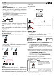
1. beschrijving 2. werking en gebruik 3. programmeren 4 ... - Niko
1. beschrijving 2. werking en gebruik 3. programmeren 4 ... - Niko
1. beschrijving 2. werking en gebruik 3. programmeren 4 ... - Niko

You also want an ePaper? Increase the reach of your titles
YUMPU automatically turns print PDFs into web optimized ePapers that Google loves.
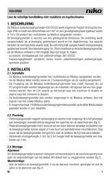
05-315<br />
Lees de volledige handleiding vóór installatie <strong>en</strong> in<strong>gebruik</strong>name.<br />
<strong>1.</strong> BESCHRIJVING<br />
Deze Easywave-z<strong>en</strong>der maakt deel uit van het <strong>Niko</strong> RF (Radio Frequ<strong>en</strong>tie) systeem, e<strong>en</strong> installatietechniek zonder<br />
bedrading tuss<strong>en</strong> de bedi<strong>en</strong>ingspunt<strong>en</strong> (drukknopp<strong>en</strong>) <strong>en</strong> de te bedi<strong>en</strong><strong>en</strong> verbruikers. We sprek<strong>en</strong> hier over<br />
e<strong>en</strong> ‘bedi<strong>en</strong>ing op afstand’ of ‘draadloze bedi<strong>en</strong>ing’. De overdracht gebeurt door radiogolv<strong>en</strong> op de frequ<strong>en</strong>tie<br />
868,3MHz. Op deze frequ<strong>en</strong>tie zijn <strong>en</strong>kel product<strong>en</strong> toegelat<strong>en</strong> die niet continu uitz<strong>en</strong>d<strong>en</strong> (1% per uur = 36s.),<br />
waardoor de kans op storing minimaal is. Het systeem le<strong>en</strong>t zich dan ook uitermate voor specifieke toepassing<strong>en</strong><br />
zoals bv. r<strong>en</strong>ovatie van geklasseerde interieurs, uitbreiding<strong>en</strong> in bestaande elektrische installaties waarbij kapwerk<br />
uitgeslot<strong>en</strong> is, bureaus met verplaatsbare wand<strong>en</strong>... of om ingewikkelde bekabeling<strong>en</strong> te vermijd<strong>en</strong>. Het systeem<br />
is modulair opgebouwd door middel van z<strong>en</strong>ders <strong>en</strong> ontvangers. De wandz<strong>en</strong>ders hebb<strong>en</strong> de vorm van e<strong>en</strong><br />
schakelaar die teg<strong>en</strong> de wand gemonteerd kan word<strong>en</strong>. De handz<strong>en</strong>ders hebb<strong>en</strong> de vorm van e<strong>en</strong> klassieke<br />
afstandsbedi<strong>en</strong>ing. Elke z<strong>en</strong>der kan e<strong>en</strong> onbeperkt aantal ontvangers tegelijkertijd stur<strong>en</strong>. Elke ontvanger kan<br />
door maximaal 32 z<strong>en</strong>ders aangestuurd word<strong>en</strong>. Deze product<strong>en</strong> zijn conform de EU-reglem<strong>en</strong>tering <strong>en</strong> voldo<strong>en</strong><br />
aan de ess<strong>en</strong>tiële eis<strong>en</strong> van de R&TTE-richtlijn: 1999/5/EC. De conformiteitsverklaring kan u opvrag<strong>en</strong> bij de<br />
<strong>Niko</strong>-supportdi<strong>en</strong>st.<br />
<strong>2.</strong> WERKING EN GEBRUIK<br />
<strong>2.</strong><strong>1.</strong> Reikwijdte tuss<strong>en</strong> Easywave-z<strong>en</strong>ders <strong>en</strong> -ontvangers<br />
Toestell<strong>en</strong> met afstandsbedi<strong>en</strong>ing zoals tv, video <strong>en</strong> audio word<strong>en</strong> niet gestoord door de Easywave-z<strong>en</strong>ders. De<br />
Easywave-z<strong>en</strong>ders moet<strong>en</strong> optisch niet gericht word<strong>en</strong> naar de ontvanger. De reikwijdte binn<strong>en</strong>shuis bedraagt<br />
±30m, in op<strong>en</strong> ruimte 100m. Het z<strong>en</strong>dbereik is afhankelijk van de in de woning <strong>gebruik</strong>te material<strong>en</strong>.<br />
U kunt ev<strong>en</strong>tueel <strong>gebruik</strong> mak<strong>en</strong> van het diagnosetoestel 05-370 om de RF-signaalsterkte te bepal<strong>en</strong> in e<strong>en</strong><br />
omgeving. Het toestel herk<strong>en</strong>t alle 868,3Mhz-signal<strong>en</strong>. Door 9 LED’s wordt de ontvangstkwaliteit van het<br />
z<strong>en</strong>dsignaal of de sterkte van de aanwezige stoorsignal<strong>en</strong> weergegev<strong>en</strong>. Zo kan u vaststell<strong>en</strong> of het bereik van<br />
de RF-z<strong>en</strong>der toereik<strong>en</strong>d is.<br />
bakste<strong>en</strong>, beton hout, gips<strong>en</strong> wand<strong>en</strong> gewap<strong>en</strong>d beton geslot<strong>en</strong> metal<strong>en</strong> ruimte<br />
verlies: 20 à 40% verlies: 5 à 20% verlies: 40 à 90% verlies: 90 à 100%<br />
<strong>2.</strong><strong>2.</strong> Batterij<strong>en</strong> plaats<strong>en</strong>/vervang<strong>en</strong><br />
- Vermijd direct contact met de batterij om ontlading te voorkom<strong>en</strong>.<br />
- Gebruik van NiCd-batterij<strong>en</strong> is niet toegelat<strong>en</strong>.<br />
- Plaats de nieuwe batterij. Respecteer hierbij de polariteit (‘+’ <strong>en</strong> ‘-‘ tek<strong>en</strong> in het compartim<strong>en</strong>t).<br />
- Gebruik 3V-batterij<strong>en</strong> CR2032 (05-315).<br />
- Gebruikte batterij<strong>en</strong> di<strong>en</strong>t u in te lever<strong>en</strong> bij e<strong>en</strong> erk<strong>en</strong>d inzamelpunt.<br />
<strong>2.</strong><strong>3.</strong> Montagevoorschrift<strong>en</strong> <strong>en</strong> aanbeveling<strong>en</strong><br />
Plaats de z<strong>en</strong>ders NOOIT:<br />
- in e<strong>en</strong> metal<strong>en</strong> verdeelkast, behuizing of vlechtwerk.<br />
- in de onmiddellijke omgeving van grote metal<strong>en</strong> object<strong>en</strong>.<br />
- op of vlakbij de grond.<br />
Knip nooit de witte draad door, dit is de ant<strong>en</strong>ne.<br />
<strong>3.</strong> PROGRAMMEREN<br />
De programmering van het Easywave RF-systeem staat volledig beschrev<strong>en</strong> in de handleiding van de Easywave<br />
RF-ontvangers.<br />
4. TROUBLESHOOTING<br />
Wanneer na programmering het systeem niet werkt, kunt u e<strong>en</strong> aantal extra controles uitvoer<strong>en</strong>.<br />
4.<strong>1.</strong> Nieuwe installatie<br />
- Controleer of er goede contactvastheid is tuss<strong>en</strong> batterij <strong>en</strong> contact<strong>en</strong>.<br />
- Controleer de netspanning op de ontvanger in de verdeelkast.<br />
- Controleer of alles is aangeslot<strong>en</strong> zoals aangegev<strong>en</strong> op de aansluitschema’s (zie handleiding ontvangers).<br />
- Reset <strong>en</strong> (her)programmeer de ontvanger (zie handleiding ontvangers; programmer<strong>en</strong>).<br />
4.<strong>2.</strong> Bestaande installatie<br />
- Controleer de batterij<strong>en</strong> van de z<strong>en</strong>der(s).<br />
- Controleer de netspanning (230V~) op de ontvanger.<br />
- Controleer de <strong>werking</strong> van de aangeslot<strong>en</strong> belasting.<br />
- Controleer of de omgeving van het systeem veranderd is waardoor er storing<strong>en</strong> zoud<strong>en</strong> kunn<strong>en</strong> optred<strong>en</strong><br />
(metal<strong>en</strong> kast<strong>en</strong>, wand<strong>en</strong> of meubels verplaatst...). Herstel de oorspronkelijke toestand, indi<strong>en</strong> mogelijk.<br />
4.<strong>3.</strong> E<strong>en</strong> z<strong>en</strong>der werkt niet<br />
Neem de z<strong>en</strong>der in de hand <strong>en</strong> loop naar de ontvanger toe.<br />
- Indi<strong>en</strong> het systeem werkt op gereduceerde afstand, is de z<strong>en</strong>der buit<strong>en</strong> het z<strong>en</strong>dbereik geplaatst of is er e<strong>en</strong><br />
probleem door storing<strong>en</strong>. U kan ev<strong>en</strong>tueel <strong>gebruik</strong> mak<strong>en</strong> van het diagnoseapparaat (05-370).<br />
- Indi<strong>en</strong> het systeem niet werkt, zelfs wanneer de z<strong>en</strong>der in de nabijheid van de ontvanger wordt gebracht,<br />
controleer de programmering (zie handleiding ontvangers; programmer<strong>en</strong>) <strong>en</strong>/of de batterij van de z<strong>en</strong>der.<br />
4.4. Het systeem schakelt zichzelf in <strong>en</strong> uit<br />
- Het systeem schakelt zichzelf in: dit kan slechts gebeur<strong>en</strong> als binn<strong>en</strong> het ontvangstbereik e<strong>en</strong> vreemde z<strong>en</strong>der<br />
in de ontvanger geprogrammeerd werd. Reset de ontvanger <strong>en</strong> herprogrammeer de gew<strong>en</strong>ste adress<strong>en</strong> (zie<br />
handleiding ontvangers; programmer<strong>en</strong>).<br />
- Het systeem schakelt zichzelf uit: de situatie kan gelijkaardig zijn aan bov<strong>en</strong>staande of kan e<strong>en</strong> gevolg zijn van<br />
kortstondige stroomonderbreking<strong>en</strong>.<br />
5. TECHNISCHE GEGEVENS<br />
Easywave-z<strong>en</strong>der 1 kanaal, 4 bedi<strong>en</strong>ingspunt<strong>en</strong> (05-315)<br />
- z<strong>en</strong>dbereik: 100m in op<strong>en</strong> lucht, gemiddeld 30m binn<strong>en</strong>shuis afhankelijk van de <strong>gebruik</strong>te material<strong>en</strong><br />
- 1 kanaal <strong>en</strong> 4 drukknopp<strong>en</strong> of 2 schakelaars<br />
- ge<strong>en</strong> bedrading tuss<strong>en</strong> bedi<strong>en</strong>ingspunt<strong>en</strong> <strong>en</strong> te bedi<strong>en</strong><strong>en</strong> verbruikers (RF-gestuurd), <strong>en</strong>kel verbinding tuss<strong>en</strong><br />
de ontvanger (schakele<strong>en</strong>heid) <strong>en</strong> het lichtpunt of apparaat<br />
- oriëntatie (richt<strong>en</strong>) van de z<strong>en</strong>ders is niet noodzakelijk (overdracht van de signal<strong>en</strong> doorhe<strong>en</strong> niet-metal<strong>en</strong><br />
wand<strong>en</strong> is mogelijk)<br />
- <strong>werking</strong>stemperatuur: -5 tot 50°C<br />
- afmeting<strong>en</strong>: 30 x 28 x 9mm<br />
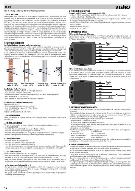
6. AANSLUITSCHEMA’S<br />
6.<strong>1.</strong> Inbouwinterface voor drukknopp<strong>en</strong><br />
Deze interface zet externe N.O.-contact<strong>en</strong> om in e<strong>en</strong> RF-telegram. Zolang het contact geslot<strong>en</strong> is, wordt het<br />
telegram verstuurd (max. 8s.). De interface is voorzi<strong>en</strong> van 4 ingang<strong>en</strong> voor externe contact<strong>en</strong> (bv. drukknopp<strong>en</strong>)<br />
<strong>en</strong> 1 ant<strong>en</strong>ne (draadkleur wit).<br />
wit<br />
bruin<br />
gro<strong>en</strong><br />
geel<br />
grijs<br />
roze select<br />
blauw common<br />
6.<strong>2.</strong> Inbouwinterface voor schakelaar<br />
De inbouwinterface voor schakelaar zet bistabiele contact<strong>en</strong> om in e<strong>en</strong> RF-telegram. Als het contact sluit, wordt<br />
de ON-code verstuurd. Als het contact op<strong>en</strong>t, wordt de OFF-code verstuurd. Tuss<strong>en</strong> het op<strong>en</strong><strong>en</strong> <strong>en</strong> sluit<strong>en</strong><br />
moet minst<strong>en</strong>s 200ms rust zijn. De interface is voorzi<strong>en</strong> van 2 ingang<strong>en</strong> voor de schakelaar <strong>en</strong> 1 ant<strong>en</strong>ne<br />
(draadkleur wit). De interface voor schakelaar is <strong>en</strong>kel geschikt voor functies met e<strong>en</strong> lage bedi<strong>en</strong>ingsfrequ<strong>en</strong>tie<br />
(bv. deurcontact<strong>en</strong>...).<br />
wit<br />
bruin<br />
gro<strong>en</strong><br />
geel<br />
grijs<br />
roze select<br />
blauw<br />
7. WETTELIJKE WAARSCHUWINGEN<br />
- De installatie di<strong>en</strong>t te word<strong>en</strong> uitgevoerd door e<strong>en</strong> bevoegd persoon <strong>en</strong> met inachtname van de geld<strong>en</strong>de<br />
voorschrift<strong>en</strong>.<br />
- Deze handleiding di<strong>en</strong>t aan de <strong>gebruik</strong>er te word<strong>en</strong> overhandigd. Zij moet bij het dossier van de elektrische<br />
installatie word<strong>en</strong> gevoegd <strong>en</strong> di<strong>en</strong>t te word<strong>en</strong> overgedrag<strong>en</strong> aan ev<strong>en</strong>tuele nieuwe eig<strong>en</strong>aars. Bijkom<strong>en</strong>de<br />
exemplar<strong>en</strong> zijn verkrijgbaar via de <strong>Niko</strong>-website of -supportdi<strong>en</strong>st.<br />
- Bij de installatie di<strong>en</strong>t rek<strong>en</strong>ing gehoud<strong>en</strong> te word<strong>en</strong> met (lijst is niet limitatief):<br />
- de geld<strong>en</strong>de wett<strong>en</strong>, norm<strong>en</strong> <strong>en</strong> reglem<strong>en</strong>t<strong>en</strong>;<br />
- de stand van de techniek op het og<strong>en</strong>blik van de installatie;<br />
- het feit dat e<strong>en</strong> handleiding alle<strong>en</strong> algem<strong>en</strong>e bepaling<strong>en</strong> vermeldt <strong>en</strong> di<strong>en</strong>t gelez<strong>en</strong> te word<strong>en</strong> binn<strong>en</strong> het<br />
kader van elke specifieke installatie;<br />
- de regels van goed vakmanschap.<br />
- Bij twijfel kan u de supportdi<strong>en</strong>st van <strong>Niko</strong> raadpleg<strong>en</strong> of contact opnem<strong>en</strong> met e<strong>en</strong> erk<strong>en</strong>d controleorganisme.<br />
Support België: Support Nederland:<br />
tel. + 32 3 778 90 80 tel. + 31 183 64 06 60<br />
website: http://www.niko.be website: http://www.niko.nl<br />
e-mail: support@niko.be e-mail: sales@niko.nl<br />
In geval van defect kan u uw product terugbezorg<strong>en</strong> aan e<strong>en</strong> erk<strong>en</strong>de <strong>Niko</strong>-groothandel sam<strong>en</strong> met e<strong>en</strong> duidelijke<br />
omschrijving van uw klacht (manier van <strong>gebruik</strong>, vastgestelde afwijking…).<br />
8. GARANTIEBEPALINGEN<br />
- Garantietermijn: twee jaar vanaf leveringsdatum. Als leveringsdatum geldt de factuurdatum van aankoop van<br />
het goed door de consum<strong>en</strong>t. Indi<strong>en</strong> ge<strong>en</strong> factuur voorhand<strong>en</strong> is, geldt de productiedatum.<br />
- De consum<strong>en</strong>t is verplicht <strong>Niko</strong> schriftelijk over het gebrek aan overe<strong>en</strong>stemming te informer<strong>en</strong>, uiterlijk binn<strong>en</strong><br />
de twee maand<strong>en</strong> na vaststelling.<br />
- In geval van e<strong>en</strong> gebrek aan overe<strong>en</strong>stemming van het goed heeft de consum<strong>en</strong>t recht op e<strong>en</strong> e<strong>en</strong> kosteloze<br />
herstelling of vervanging, wat door <strong>Niko</strong> bepaald wordt.<br />
- <strong>Niko</strong> is niet verantwoordelijk voor e<strong>en</strong> gebrek of schade als gevolg van e<strong>en</strong> foutieve installatie, oneig<strong>en</strong>lijk of<br />
onachtzaam <strong>gebruik</strong> of verkeerde bedi<strong>en</strong>ing of transformatie van het goed.<br />
- De dwing<strong>en</strong>de bepaling<strong>en</strong> van de nationale wetgeving<strong>en</strong> betreff<strong>en</strong>de de verkoop van consumptiegoeder<strong>en</strong> <strong>en</strong> de<br />
bescherming van de consum<strong>en</strong>t<strong>en</strong> van de land<strong>en</strong> waarin <strong>Niko</strong> rechtstreeks of via zuster/dochterv<strong>en</strong>nootschapp<strong>en</strong>,<br />
filial<strong>en</strong>, distributeurs, ag<strong>en</strong>t<strong>en</strong> of vaste verteg<strong>en</strong>woordigers verkoopt, hebb<strong>en</strong> voorrang op bov<strong>en</strong>staande<br />
bepaling<strong>en</strong>.<br />
nv <strong>Niko</strong> sa Industriepark West 40, BE-9100 Sint-Niklaas, Belgium — tel. +32 3 778 90 00 — fax +32 3 777 71 20 — e-mail: support@<strong>Niko</strong>.be — www.niko.be PM005-31500R08171
05-315<br />
Lisez <strong>en</strong>tièrem<strong>en</strong>t le mode d’emploi avant toute installation et mise <strong>en</strong> service.<br />
<strong>1.</strong> DESCRIPTION<br />
Cet émetteur Easywave fait partie de la gamme des systèmes RF <strong>Niko</strong> (Fréqu<strong>en</strong>ce Radio), une technique<br />
d’installation totalem<strong>en</strong>t exempte de câblage <strong>en</strong>tre les points de commande (boutons-poussoirs) et les appareils<br />
à commander. Il s’agit d’un système de ‘commande à distance’. La transmission s’effectue via des ondes radio<br />
d’une fréqu<strong>en</strong>ce de 868,3MHz. A cette fréqu<strong>en</strong>ce, seuls des produits qui n’émett<strong>en</strong>t que durant 1% d’une<br />
heure sont autorisés, ce qui minimise les risques d’interfér<strong>en</strong>ce. Le système se prête particulièrem<strong>en</strong>t bi<strong>en</strong> aux<br />
applications spécifiques comme la rénovation d’intérieurs classés, l’ext<strong>en</strong>sion d’installations électriques existantes<br />
pour lesquelles des travaux de perçage sont exclus, les bureaux à cloisons mobiles, etc. ou pour éviter des travaux<br />
de câblage complexes. Le système se construit de façon modulaire au moy<strong>en</strong> d’émetteurs et de récepteurs. Les<br />
émetteurs muraux ont la forme d’un interrupteur à installer sur un mur. Les émetteurs portables ont la forme<br />
d’une commande à distance classique. Chaque émetteur peut commander un nombre illimité de récepteurs<br />
<strong>en</strong> même temps. Chaque récepteur peut être contrôlé par un maximum de 32 émetteurs. Ces produits sont<br />
conformes à la réglem<strong>en</strong>tation UE et satisfais<strong>en</strong>t aux exig<strong>en</strong>ces ess<strong>en</strong>tielles de la directive R&TTE: 1999/5/CE.<br />
La déclaration de conformité peut être obt<strong>en</strong>ue auprès du service ‘support’ <strong>Niko</strong>.<br />
<strong>2.</strong> FONCTIONNEMENT ET UTILISATION<br />
<strong>2.</strong><strong>1.</strong> Portée <strong>en</strong>tre émetteurs et récepteurs Easywave<br />
Des appareils avec commande à distance, tels que télévision, vidéo et audio, ne sont pas parasités par des<br />
émetteurs Easywave. Les émetteurs Easywave ne doiv<strong>en</strong>t pas nécessairem<strong>en</strong>t être ori<strong>en</strong>tés vers le récepteur.<br />
La portée s’élève à ±30m à l’intérieur et à ±100m à l’air libre. La distance d’émission dép<strong>en</strong>d des matériaux<br />
utilisés dans la maison.<br />
Vous pouvez év<strong>en</strong>tuellem<strong>en</strong>t utiliser l’appareil diagnostic 05-370 afin de déterminer l’int<strong>en</strong>sité de réception RF<br />
dans un lieu. L’appareil reconnaît tous les signaux 868,3MHz. 9 LED vous inform<strong>en</strong>t sur la qualité de réception<br />
du signal émetteur ou de l’int<strong>en</strong>sité des signaux parasites. Cela vous permet de déterminer si la portée de<br />
l’émetteur RF suffit.<br />
briques, béton bois, parois <strong>en</strong> plâtre béton armé espace <strong>en</strong> métal fermé<br />
perte: 20 à 40% perte: 5 à 20% perte: 40 à 90% perte: 90 à 100%<br />
<strong>2.</strong><strong>2.</strong> Installation/remplacem<strong>en</strong>t de la pile<br />
- Evitez le contact direct avec la pile, afin qu’elle ne se décharge pas.<br />
- L’utilisation de piles NiCd n’est pas autorisée.<br />
- Insérez la nouvelle pile. Respectez la polarité (voir signe ‘+’ et ‘-‘).<br />
- Utilisez une pile 3V CR2032 (05-315)<br />
- Des piles usagées doiv<strong>en</strong>t être apportées à un c<strong>en</strong>tre de collecte agréé.<br />
<strong>2.</strong><strong>3.</strong> Instructions de montage et recommandations<br />
Ne placez JAMAIS l’émetteur:<br />
- dans une armoire de distribution, une boîte ou un chemin de câbles métalliques.<br />
- à proximité immédiate de grands objets métalliques.<br />
- sur ou à proximité du sol.<br />
Ne coupez jamais le fil blanc, c’est l’ant<strong>en</strong>ne.<br />
<strong>3.</strong> PROGRAMMATION<br />
La programmation du système RF Easywave est intégralem<strong>en</strong>t décrite dans le mode d’emploi des récepteurs<br />
RF Easywave.<br />
4. DERANGEMENTS<br />
Si le système ne fonctionne pas après l’installation, vous pouvez faire des contrôles supplém<strong>en</strong>taires.<br />
4.<strong>1.</strong> Nouvelle installation<br />
- Contrôlez si le contact <strong>en</strong>tre la pile et les contacts est bi<strong>en</strong> établi.<br />
- Contrôlez la t<strong>en</strong>sion de réseau sur le récepteur dans l’armoire de distribution.<br />
- Contrôlez si tout a été connecté comme indiqué sur le schéma de raccordem<strong>en</strong>t (voir mode d’emploi des<br />
récepteurs).<br />
- Réinitialisez et (re)programmez le récepteur (voir mode d’emploi des récepteurs; programmation).<br />
4.<strong>2.</strong> Installation existante<br />
- Contrôlez les piles de l’ (des) émetteur(s).<br />
- Contrôlez la t<strong>en</strong>sion du réseau (230V~) sur le récepteur.<br />
- Contrôlez le fonctionnem<strong>en</strong>t de la charge connectée.<br />
- Contrôlez si l’<strong>en</strong>vironnem<strong>en</strong>t du système n’a pas changé, pouvant provoquer des perturbations (armoires<br />
métalliques, déplacem<strong>en</strong>t de meubles ou de parois …). Essayez de rétablir l’état d’origine.<br />
4.<strong>3.</strong> Un émetteur ne fonctionne pas<br />
T<strong>en</strong>ez l’émetteur dans la main et marchez <strong>en</strong> direction du récepteur.<br />
- Si le système fonctionne <strong>en</strong> diminuant la distance, l’émetteur se trouve <strong>en</strong> dehors de la zone d’émission ou il<br />
y a un problème d’interfér<strong>en</strong>ce. (Vous pouvez év<strong>en</strong>tuellem<strong>en</strong>t utiliser l’appareil diagnostic 05-370).<br />
- Si le système ne fonctionne pas, même lorsque l’émetteur est à proximité du récepteur, contrôlez la programmation<br />
(voir mode d’emploi des récepteurs; programmation) et/ou la pile de l’émetteur.<br />
4.4. Le système s’<strong>en</strong>cl<strong>en</strong>che ou se décl<strong>en</strong>che de lui-même<br />
- Le système s’<strong>en</strong>cl<strong>en</strong>che de lui-même: dans la portée de ce récepteur est programmé un autre émetteur.<br />
Déprogrammez le récepteur et reprogrammez les adresses souhaitées (voir mode d’emploi des récepteurs;<br />
programmation).<br />
- Le système se décl<strong>en</strong>che de lui-même: situation analogue au point précéd<strong>en</strong>t ou bi<strong>en</strong> le décl<strong>en</strong>chem<strong>en</strong>t est<br />
dû à de courtes coupures de courant.<br />
5. CARACTERISTIQUES TECHNIQUES<br />
Emetteur portable Easywave à 1 canal, 4 points de commande (05-315)<br />
- distance d’émission: 100m <strong>en</strong> champ libre, <strong>en</strong>viron 30m à l’intérieur (dép<strong>en</strong>d des matériaux utilisés)<br />
- 1 canal et 4 boutons-poussoirs ou 2 interrupteurs<br />
- aucun câblage <strong>en</strong>tre les points de commande et les appareils à commander (commande RF); la seule connexion<br />
est celle <strong>en</strong>tre l’unité de commutation réceptrice et le point lumineux ou l’appareil<br />
- L’ori<strong>en</strong>tation des émetteurs vers le récepteur n’est pas nécessaire (la transmission au travers de cloisons non<br />
métalliques est possible)<br />
- température de fonctionnem<strong>en</strong>t: -5 à 50°C<br />
- dim<strong>en</strong>sions: 30 x 28 x 9mm<br />
6. SCHEMAS DE RACCORDEMENT<br />
6.<strong>1.</strong> Interface à <strong>en</strong>castrer pour boutons-poussoirs<br />
Cette interface a pour but de transformer les impulsions des contacts N.O. <strong>en</strong> un signal RF (télégramme). Le<br />
signal RF est prés<strong>en</strong>t aussi longtemps que le bouton-poussoir est <strong>en</strong>foncé (max. 8s.).<br />
L’interface possède 4 <strong>en</strong>trées pour contacts externes (p.ex. boutons-poussoirs) et 1 ant<strong>en</strong>ne (couleur du fil:<br />
blanc).<br />
blanc<br />
brun<br />
vert<br />
jaune<br />
gris<br />
roze select<br />
bleu cond. commun<br />
6.<strong>2.</strong> Interface à <strong>en</strong>castrer pour interrupteur<br />
L’interface à <strong>en</strong>castrer pour interrupteur transforme les impulsions des contacts bistables <strong>en</strong> un télégramme RF.<br />
L’ouverture du contact correspond au code ON. La fermeture du contact correspond au code OFF.<br />
Un intervalle de 200ms doit au moins être prés<strong>en</strong>t <strong>en</strong>tre l’ouverture et la fermeture.<br />
L’interface possède 2 <strong>en</strong>trées pour l’interrupteur et l’ant<strong>en</strong>ne (couleur du fil: blanc).<br />
Cette interface est uniquem<strong>en</strong>t d’application pour des fonctions ayant une basse fréqu<strong>en</strong>ce de commande<br />
(p.ex. contacts de portes...).<br />
blanc<br />
brun<br />
vert<br />
jaune<br />
gris<br />
roze select<br />
bleu<br />
7. PRESCRIPTIONS LEGALES<br />
- L’installation doit être effectuée par une personne compét<strong>en</strong>te et dans le respect des prescriptions <strong>en</strong><br />
vigueur.<br />
- Ce mode d’emploi doit être remis à l’utilisateur. Il doit être joint au dossier de l’installation électrique et être<br />
remis à d’év<strong>en</strong>tuels autres propriétaires. Des exemplaires supplém<strong>en</strong>taires peuv<strong>en</strong>t être obt<strong>en</strong>us sur le site<br />
web ou auprès du service ‘support <strong>Niko</strong>’.<br />
- Il y a lieu de t<strong>en</strong>ir compte des points suivants avant l’installation (liste non limitative):<br />
- les lois, normes et réglem<strong>en</strong>tations <strong>en</strong> vigueur;<br />
- l’état de la technique au mom<strong>en</strong>t de l’installation;<br />
- ce mode d’emploi qui doit être lu dans le cadre de toute installation spécifique;<br />
- les règles de l’art.<br />
- En cas de doute, vous pouvez appeler le service ‘support <strong>Niko</strong>’ ou vous adresser à un organisme de contrôle<br />
reconnu.<br />
Support Belgique: Support France:<br />
+ 32 3 778 90 80 + 33 820 20 6625<br />
site web: http://www.niko.be site web: http://www.niko.fr<br />
e-mail: support@niko.be e-mail: v<strong>en</strong>tes@niko.fr<br />
En cas de défaut de votre appareil, vous pouvez le retourner à un grossiste <strong>Niko</strong> agréé, accompagné d’une<br />
description détaillée de votre plainte (manière d’utilisation, diverg<strong>en</strong>ce constatée…).<br />
8. DISPOSITIONS DE GARANTIE<br />
- Délai de garantie: 2 ans à partir de la date de livraison. La date de la facture d’achat par le consommateur fait<br />
office de date de livraison. Sans facture disponible, la date de fabrication est seule valable.<br />
- Le consommateur est t<strong>en</strong>u de prév<strong>en</strong>ir <strong>Niko</strong> par écrit de tout manquem<strong>en</strong>t à la concordance des produits dans<br />
un délai max. de 2 mois après constatation.<br />
- Au cas ou pareil manquem<strong>en</strong>t serait constaté, le consommateur a droit à une réparation gratuite ou à un<br />
remplacem<strong>en</strong>t gratuit selon l’avis de <strong>Niko</strong>.<br />
- <strong>Niko</strong> ne peut être t<strong>en</strong>u pour responsable pour un défaut ou des dégâts suite à une installation fautive, à une<br />
utilisation contraire ou inadaptée ou à une transformation du produit.<br />
- Les dispositions contraignantes des législations nationales ayant trait à la v<strong>en</strong>te de bi<strong>en</strong>s de consommation et la<br />
protection des consommateurs des différ<strong>en</strong>ts pays où <strong>Niko</strong> procède à la v<strong>en</strong>te directe ou par <strong>en</strong>treprises interposées,<br />
filiales, distributeurs, ag<strong>en</strong>ts ou représ<strong>en</strong>tants fixes, préval<strong>en</strong>t sur les dispositions susm<strong>en</strong>tionnées.<br />
nv <strong>Niko</strong> sa Industriepark West 40, BE-9100 Sint-Niklaas, Belgium — tel. +32 3 778 90 00 — fax +32 3 777 71 20 — e-mail: support@<strong>Niko</strong>.be — www.niko.be PM005-31500R08171
05-315<br />
Les<strong>en</strong> Sie vor der Montage und Inbetriebnahme die vollständige Gebrauchsanleitung.<br />
<strong>1.</strong> BESCHREIBUNG<br />
Dieser Easywave-S<strong>en</strong>der gehört zum <strong>Niko</strong>-Funk-System, einer Installationstechnik die ohne jede Verdrahtung<br />
zwisch<strong>en</strong> d<strong>en</strong> Bedi<strong>en</strong>ungspunkt<strong>en</strong> (Tastern) und d<strong>en</strong> zu steuernd<strong>en</strong> Gerät<strong>en</strong> auskommt. Wir sprech<strong>en</strong> hier von<br />
einer ‚Fernbedi<strong>en</strong>ung’. Die Übertragung erfolgt auf der Europäisch harmonisiert<strong>en</strong> Frequ<strong>en</strong>z von 868,3MHz.<br />
Auf dieser Frequ<strong>en</strong>z sind nur Produkte zugelass<strong>en</strong>, die lediglich 1% = 36s. pro Stunde s<strong>en</strong>d<strong>en</strong>. Hierdurch wird<br />
das Störungsrisiko auf ein Minimum reduziert. Das System eignet sich daher auch besonders gut für spezielle<br />
Einsatzfälle wie z.B. die R<strong>en</strong>ovierung d<strong>en</strong>kmalgeschützter Inn<strong>en</strong>räume oder die Erweiterung bereits vorhand<strong>en</strong>er<br />
Installation<strong>en</strong>, wo Stemmarbeit<strong>en</strong> ausgeschloss<strong>en</strong> sind, in Büros mit mobil<strong>en</strong> Wänd<strong>en</strong>... um hier die Kabelinstallation<br />
zu vermeid<strong>en</strong>. Das System von S<strong>en</strong>dern und Empfängern ist modular aufgebaut. Die Wands<strong>en</strong>der hab<strong>en</strong> die Form<br />
eines Schalters, der auf der Wand montiert werd<strong>en</strong> kann. Die Hands<strong>en</strong>der hab<strong>en</strong> die Form einer klassisch<strong>en</strong><br />
Funkfernbedi<strong>en</strong>ung. Jeder S<strong>en</strong>der kann eine unbegr<strong>en</strong>zte Anzahl von Empfängern gleichzeitig steuern. Jeder<br />
Empfänger kann von maximal 32 S<strong>en</strong>dern angesteuert werd<strong>en</strong>. Diese Produkte <strong>en</strong>tsprech<strong>en</strong> d<strong>en</strong> EU-Vorschrift<strong>en</strong><br />
und erfüll<strong>en</strong> die wes<strong>en</strong>tlich<strong>en</strong> Anforderung<strong>en</strong> der R&TTE-Richtlinie 1999/5/EC. Die Konformitätsbescheinigung<br />
erhalt<strong>en</strong> Sie bei der <strong>Niko</strong>-Hotline.<br />
<strong>2.</strong> FUNKTIONSWEISE UND ANWENDUNG<br />
<strong>2.</strong><strong>1.</strong> S<strong>en</strong>debereich zwisch<strong>en</strong> Easywave-S<strong>en</strong>der und Easywave-Empfänger<br />
Geräte mit Fernbedi<strong>en</strong>ung<strong>en</strong> wie Fernseh-, Video- und Audiogeräte werd<strong>en</strong> nicht durch Easywave-S<strong>en</strong>der<br />
gestört. Die Easywave-S<strong>en</strong>der müss<strong>en</strong> nicht optisch zum Empfänger ausgerichtet werd<strong>en</strong>. Der S<strong>en</strong>debereich<br />
beläuft sich auf ca. 30m im Haus und auf 100m im Frei<strong>en</strong>. Der S<strong>en</strong>debereich ist von d<strong>en</strong> im Gebäude b<strong>en</strong>utzt<strong>en</strong><br />
Materiali<strong>en</strong> abhängig.<br />
Sie könn<strong>en</strong> ev<strong>en</strong>tuell das Diagnosegerät 05-370 verw<strong>en</strong>d<strong>en</strong>, um die Stärke des Funksignals in der Umgebung<br />
zu bestimm<strong>en</strong>. Das Gerät erk<strong>en</strong>nt alle 868,3MHz-Signale. Durch die 9 LED’s wird die Stärke des S<strong>en</strong>designals<br />
bzw. die der Störsignale wiedergegeb<strong>en</strong>. Die LED’s ermöglich<strong>en</strong> die Bestimmung des S<strong>en</strong>debereichs der<br />
Wands<strong>en</strong>der.<br />
Backstein, Beton Holz, Gipswände Stahlbeton Geschloss<strong>en</strong>e Metallwände<br />
Verlust: 20 bis 40% Verlust: 5 bis 20% Verlust: 40 bis 90% Verlust: 90 bis 100%<br />
<strong>2.</strong><strong>2.</strong> Batterie installier<strong>en</strong>/austausch<strong>en</strong><br />
- Vermeid<strong>en</strong> Sie die direkte Berührung der Batteriekontakte, um eine vorzeitige Entladung zu vermeid<strong>en</strong>.<br />
- Der Einsatz von NiCd-Akkus ist nicht zugelass<strong>en</strong>.<br />
- Installier<strong>en</strong> Sie die neue Batterie. Beacht<strong>en</strong> Sie die Polarität (‘+’ und ‘-’) wie im Batteriefach angedeutet.<br />
- Verw<strong>en</strong>d<strong>en</strong> Sie eine Batterie 3V CR2032 (05-315).<br />
- B<strong>en</strong>utzte Batteri<strong>en</strong> müss<strong>en</strong> umweltfreundlich <strong>en</strong>tsorgt werd<strong>en</strong>.<br />
<strong>2.</strong><strong>3.</strong> Montagevorschrift<strong>en</strong> und Empfehlung<strong>en</strong><br />
Montier<strong>en</strong> Sie die S<strong>en</strong>der NIEMALS:<br />
- in ein<strong>en</strong> Verteilerkast<strong>en</strong> oder ein Gehäuse aus Metall.<br />
- in der unmittelbar<strong>en</strong> Nähe von groß<strong>en</strong> Metallobjekt<strong>en</strong>.<br />
- auf dem Bod<strong>en</strong> (oder in dess<strong>en</strong> Nähe).<br />
Schneid<strong>en</strong> Sie niemals d<strong>en</strong> weiß<strong>en</strong> Draht ab, dies ist die Ant<strong>en</strong>ne.<br />
<strong>3.</strong> PROGRAMMIERUNG<br />
Die Programmierung des Easywave-Funkfernbedi<strong>en</strong>ungssystems wird vollständig in der Anleitung der Easywave-<br />
Empfänger beschrieb<strong>en</strong>.<br />
4. FEHLERBEHEBUNG<br />
W<strong>en</strong>n nach der Programmierung das System nicht funktioniert, könn<strong>en</strong> Sie zusätzliche Kontroll<strong>en</strong> ausführ<strong>en</strong>.<br />
4.<strong>1.</strong> Bei einer Neuinstallation<br />
- Kontrollier<strong>en</strong> Sie, ob die Kontakte an der Batterie gut anlieg<strong>en</strong>.<br />
- Kontrollier<strong>en</strong> Sie die Netzspannung am Empfänger (LED) im Verteilerkast<strong>en</strong>.<br />
- Kontrollier<strong>en</strong> Sie, ob alles d<strong>en</strong> Schaltplän<strong>en</strong> <strong>en</strong>tsprech<strong>en</strong>d angeschloss<strong>en</strong> ist (s. Gebrauchsanleitung Empfänger).<br />
- Führ<strong>en</strong> Sie beim Empfänger ein Reset durch oder programmier<strong>en</strong> Sie dies<strong>en</strong> neu (s. Gebrauchsanleitung<br />
Empfänger: Programmierung).<br />
4.<strong>2.</strong> Bei vorhand<strong>en</strong><strong>en</strong> Anlag<strong>en</strong><br />
- Kontrollier<strong>en</strong> Sie d<strong>en</strong> Zustand der Batteri<strong>en</strong> des/der S<strong>en</strong>der(s).<br />
- Kontrollier<strong>en</strong> Sie die Netzspannung (230V~) am Empfänger.<br />
- Kontrollier<strong>en</strong> Sie die Funktion des angeschloss<strong>en</strong><strong>en</strong> Verbrauchers.<br />
- Kontrollier<strong>en</strong> Sie, ob im Umfeld des Systems Veränderung<strong>en</strong> durchgeführt wurd<strong>en</strong>, die Störung<strong>en</strong> verursach<strong>en</strong><br />
könnt<strong>en</strong> (Metallschränke, Wände oder Möbel wurd<strong>en</strong> umgesetzt…). Stell<strong>en</strong> Sie – w<strong>en</strong>n möglich – d<strong>en</strong><br />
ursprünglich<strong>en</strong> Zustand wieder her.<br />
4.<strong>3.</strong> Ein S<strong>en</strong>der funktioniert nicht<br />
Nehm<strong>en</strong> Sie d<strong>en</strong> S<strong>en</strong>der in die Hand und geh<strong>en</strong> Sie in Richtung Empfänger.<br />
- W<strong>en</strong>n das System bei reduziertem Abstand funktioniert, wurde der S<strong>en</strong>der außerhalb des S<strong>en</strong>debereichs<br />
montiert oder wird er gestört. Sie könn<strong>en</strong> ev<strong>en</strong>tuell das Diagnosegerät 05-370 verw<strong>en</strong>d<strong>en</strong>.<br />
- W<strong>en</strong>n das System selbst dann nicht funktioniert, w<strong>en</strong>n der S<strong>en</strong>der in der Nähe des Empfängers montiert wird,<br />
überprüf<strong>en</strong> Sie die Programmierung (s. Gebrauchsanleitung Empfänger: Programmierung) und/oder die Batterie<br />
des S<strong>en</strong>ders.<br />
4.4. Das System schaltet sich selbsttätig an und aus<br />
- Das System schaltet sich selbsttätig an: Dies kann nur gescheh<strong>en</strong>, w<strong>en</strong>n innerhalb des Empfangsbereichs ein<br />
fremder S<strong>en</strong>der betätigt wird, der vorher eb<strong>en</strong>falls im Empfänger programmiert wurde. Führ<strong>en</strong> Sie ein Reset<br />
des Empfängers durch und programmier<strong>en</strong> Sie die gewünscht<strong>en</strong> S<strong>en</strong>der noch einmal (s. Anleitung Empfänger;<br />
Programmierung).<br />
- Das System schaltet sich selbsttätig aus: Die Situation kann ähnlich der ob<strong>en</strong> beschrieb<strong>en</strong><strong>en</strong> Situation oder<br />
eine Folge kurzzeitiger Stromausfälle sein.<br />
5. TECHNISCHE DATEN<br />
Easywave-1-Kanal-S<strong>en</strong>der, 4 Funktion<strong>en</strong> (05-315)<br />
- S<strong>en</strong>debereich: 100m im Frei<strong>en</strong>, durchschnittlich 30m im Haus (abhängig von d<strong>en</strong> b<strong>en</strong>utzt<strong>en</strong> Materiali<strong>en</strong>)<br />
- 1 Kanal und 4 Taster oder 2 Schalter<br />
- keine Verdrahtung zwisch<strong>en</strong> d<strong>en</strong> Bedi<strong>en</strong>ungspunkt<strong>en</strong> und d<strong>en</strong> zu bedi<strong>en</strong><strong>en</strong>d<strong>en</strong> Gerät<strong>en</strong> (funkgesteuert), nur<br />
ein Kabel zwisch<strong>en</strong> der Empfänger-Schalteinheit und der Lichtquelle oder dem Gerät<br />
- ein Ausricht<strong>en</strong> des S<strong>en</strong>ders ist nicht erforderlich (eine Übertragung von Signal<strong>en</strong> durch nicht-metallische Wände<br />
ist möglich)<br />
- Betriebstemperatur: -5 bis 50°C<br />
- Abmessung<strong>en</strong>: 30 x 28 x 9mm<br />
6. ANSCHLUSSSCHEMATA<br />
6.<strong>1.</strong> UP-Interface für Taster<br />
Dieses Interface setzt monostabile Öffnerkontaktsignale in ein Funktelegramm um. Solange der Kontakt<br />
geschloss<strong>en</strong> ist, werd<strong>en</strong> Telegramme ges<strong>en</strong>det (max. 8s.). Das Interface besitzt 4 Tastereingänge (z.B. Taster)<br />
und eine Ant<strong>en</strong>ne (Drahtfarbe: weiß).<br />
weiß<br />
braun<br />
grün<br />
gelb<br />
grau<br />
rosa select<br />
blau gemeinsamer Leiter<br />
6.<strong>2.</strong> UP-Interface für Schalter<br />
Dieses Interface setzt bistabile Schließerkontaktsignale in ein Funktelegramm um. Sobald der Kontakt geschloss<strong>en</strong><br />
wird, wird ein ON-Telegramm ges<strong>en</strong>det. Wird der Kontakt wieder geöffnet, so wird ein OFF-Telegramm ges<strong>en</strong>det.<br />
Zwisch<strong>en</strong> dem Öffn<strong>en</strong> und Schließ<strong>en</strong> des Kontaktes müss<strong>en</strong> mindest<strong>en</strong>s 200ms Paus<strong>en</strong>zeit lieg<strong>en</strong>. Dieses Interface<br />
besitzt 2 Schaltereingänge und eine Ant<strong>en</strong>ne (Drahtfarbe: weiß). Das Schalterinterface wird für Schaltfunktion<strong>en</strong><br />
mit niedriger Bedi<strong>en</strong>frequ<strong>en</strong>z (z.B. Türkontakte…) empfohl<strong>en</strong>.<br />
weiß<br />
braun<br />
grün<br />
gelb<br />
grau<br />
rosa select<br />
blau<br />
7. GESETZLICHE BESTIMMUNGEN<br />
- Die Installation darf ausschließlich von einem Fachmann des Elektrohandwerks unter Berücksichtigung der<br />
gelt<strong>en</strong>d<strong>en</strong> Vorschrift<strong>en</strong> vorg<strong>en</strong>omm<strong>en</strong> werd<strong>en</strong>.<br />
- Übergeb<strong>en</strong> Sie dem B<strong>en</strong>utzer diese Gebrauchsanleitung. Sie ist d<strong>en</strong> Unterlag<strong>en</strong> der elektrisch<strong>en</strong> Anlage<br />
beizufüg<strong>en</strong> und muss auch ev<strong>en</strong>tuell<strong>en</strong> neu<strong>en</strong> Besitzern übergeb<strong>en</strong> werd<strong>en</strong>. Zusätzliche Exemplare erhalt<strong>en</strong><br />
Sie über unsere Website oder unser<strong>en</strong> Servicedi<strong>en</strong>st.<br />
- Bei der Installation müss<strong>en</strong> Sie u.a. Folg<strong>en</strong>des berücksichtig<strong>en</strong>:<br />
- die gelt<strong>en</strong>d<strong>en</strong> Gesetze, Norm<strong>en</strong> und Vorschrift<strong>en</strong>;<br />
- d<strong>en</strong> Stand der Technik zum Zeitpunkt der Installation;<br />
- diese Gebrauchsanleitung die im Zusamm<strong>en</strong>hang mit jeder spezifisch<strong>en</strong> Anlage geseh<strong>en</strong> werd<strong>en</strong> muss;<br />
- die Regeln fachmännisch<strong>en</strong> Könn<strong>en</strong>s.<br />
- Sollt<strong>en</strong> Sie Frag<strong>en</strong> hab<strong>en</strong>, könn<strong>en</strong> Sie sich an die <strong>Niko</strong>-Hotline oder an eine anerkannte Kontrollstelle w<strong>en</strong>d<strong>en</strong>:<br />
Web-site: http://www.niko.be; E-Mail: support@niko.be;<br />
Hotline Belgi<strong>en</strong>: +32 3 778 90 80<br />
Hotline Moeller Deutschland:<br />
Berlin: +49 30 701902-46 Hamburg: +49 40 75019-281<br />
Düsseldorf: +49 2131 317-37 Frankfurt a.M.: +49 69 50089-263<br />
Stuttgart: +49 711 68789-51 Münch<strong>en</strong>: +49 89 460 95-218<br />
Mail: gebaeudeautomation@moeller.net<br />
Österreich: Moeller Gebäudeautomation UG Schrems 0043-2853-702-0<br />
Hotline Slowakei: +421 263 825 155 – E-mail: niko@niko.sk<br />
Im Falle eines Defektes an Ihrem <strong>Niko</strong>-Produkt, könn<strong>en</strong> Sie dieses mit einer g<strong>en</strong>au<strong>en</strong> Fehlerbeschreibung<br />
(Anw<strong>en</strong>dungsproblem, festgestellter Fehler, usw.) an Ihr<strong>en</strong> Moeller- oder <strong>Niko</strong>-EGH zurückbring<strong>en</strong>.<br />
8. GARANTIEBESTIMMUNGEN<br />
- Garantiezeitraum: Zwei Jahre ab Lieferdatum. Als Lieferdatum gilt das Rechnungsdatum zu dem der Endkunde<br />
das Produkt gekauft hat. Falls keine Rechnung mehr vorhand<strong>en</strong> ist, gilt das Produktionsdatum.<br />
- Der Endkunde ist verpflichtet, <strong>Niko</strong> über d<strong>en</strong> festgestellt<strong>en</strong> Mangel innerhalb von zwei Monat<strong>en</strong> zu<br />
informier<strong>en</strong>.<br />
- Im Falle eines Mangels an dem Produkt hat der Endkunde das Recht auf eine kost<strong>en</strong>lose Reparatur oder Ersatz.<br />
Dies wird von <strong>Niko</strong> <strong>en</strong>tschied<strong>en</strong>.<br />
- <strong>Niko</strong> ist nicht für ein<strong>en</strong> Mangel oder Schad<strong>en</strong> verantwortlich, der durch unsachgemäße Installation, nicht<br />
bestimmungsgemäß<strong>en</strong> oder unvorsichtig<strong>en</strong> Gebrauch oder falsche Bedi<strong>en</strong>ung oder Anpass<strong>en</strong>/Ändern des<br />
Produktes <strong>en</strong>tsteht.<br />
- Die zwing<strong>en</strong>d<strong>en</strong> Vorschrift<strong>en</strong> der national<strong>en</strong> Gesetzgebung bezüglich des Verkaufs von Konsumgütern und<br />
der Schutz des Kund<strong>en</strong> in d<strong>en</strong> Ländern in d<strong>en</strong><strong>en</strong> <strong>Niko</strong> direkt oder über seine Tochtergesellschaft<strong>en</strong>, Filial<strong>en</strong>,<br />
Distributor<strong>en</strong>, Handelsvertretung<strong>en</strong> oder Vertretern verkauft, hab<strong>en</strong> Vorrang vor d<strong>en</strong> obig<strong>en</strong> Bestimmung<strong>en</strong>.<br />
nv <strong>Niko</strong> sa Industriepark West 40, BE-9100 Sint-Niklaas, Belgium — tel. +32 3 778 90 00 — fax +32 3 777 71 20 — e-mail: support@<strong>Niko</strong>.be — www.niko.be PM005-31500R08171
05-315<br />
Read the complete manual before attempting installation and activating the system.<br />
<strong>1.</strong> DESCRIPTION<br />
This Easywave transmitter is part of the <strong>Niko</strong> RF (Radio Frequ<strong>en</strong>cy) system, an installation technique that does<br />
not require any wiring betwe<strong>en</strong> the control points (push buttons) and the consumers to be operated. This<br />
technique is known as ‘remote control’ or ‘wireless control’. Transmission occurs by means of radio waves at<br />
the 868.3MHz frequ<strong>en</strong>cy. This frequ<strong>en</strong>cy is reserved for products that do not transmit continuously (1% per<br />
hour = 36s.), so that there is only a minimal risk of interfer<strong>en</strong>ce. The system is therefore ideally suitable for<br />
use in specific applications such as r<strong>en</strong>ovation of interiors, ext<strong>en</strong>sions in existing electrical installations where<br />
drilling or channeling work is excluded, offices with movable walls… or to avoid the use of complex cabling<br />
configurations. It is a modular system built around transmitters and receivers. The wall mounted transmitters<br />
take the form of an ordinary switch that can be wall mounted. The hand held transmitters take the form of a<br />
conv<strong>en</strong>tional remote control unit. Each transmitter can control an unlimited number of receivers simultaneously.<br />
Each receiver can be controlled by up to 32 transmitters. These products are in conformity with the EG regulations<br />
and comply with the ess<strong>en</strong>tial requirem<strong>en</strong>ts of the R&TTE directive 1999/5/EC. The certificate of conformity can<br />
be obtained from the <strong>Niko</strong> support service.<br />
<strong>2.</strong> OPERATION AND USE<br />
<strong>2.</strong><strong>1.</strong> Range betwe<strong>en</strong> Easywave transmitters and receivers<br />
Equipm<strong>en</strong>t using a remote control, such as TV, video and audio, does not suffer interfer<strong>en</strong>ce from the Easywave<br />
transmitters. The Easywave transmitters need not be pointed at the receiver. The range in buildings amounts to<br />
approx. 30m. In op<strong>en</strong> fields, ranges of up to 100m are possible. The transmitter range dep<strong>en</strong>ds on the materials<br />
used in the building.<br />
You can also use diagnosis unit 05-370 to determine the RF signal str<strong>en</strong>gth in a giv<strong>en</strong> <strong>en</strong>vironm<strong>en</strong>t. The device<br />
detects all 868,3MHz signals. The reception quality of the transmitter signal or the str<strong>en</strong>gth of the interfering signals<br />
pres<strong>en</strong>t is indicated by 9 LEDs, allowing you to determine whether the RF transmitter’s range is suffici<strong>en</strong>t.<br />
brick, concrete wood, plaster walls reinforced concrete <strong>en</strong>closure in metall<br />
loss: 20 to 40% loss: 5 to 20% loss: 40 to 90% loss: 90 to 100%<br />
<strong>2.</strong><strong>2.</strong> Inserting/replacing batteries<br />
- Avoid direct contact with the battery to prev<strong>en</strong>t it from discharging.<br />
- Check that no NiCd batteries are used.<br />
- Insert the new battery. Observe the polarity (‘+’ and ‘-‘ symbols in the compartm<strong>en</strong>t).<br />
- Use a 3V CR2032 (05-315) battery.<br />
- Used batteries are to be returned to an authorised waste collection point.<br />
<strong>2.</strong><strong>3.</strong> Mounting instructions and recomm<strong>en</strong>dations<br />
NEVER install the transmitters:<br />
- in a metal distribution box, housing or netting;<br />
- in the immediate vicinity of large metal objects;<br />
- on or near the floor.<br />
Never cut the white wire, this is the ant<strong>en</strong>na.<br />
<strong>3.</strong> PROGRAMMING<br />
How to program your Easywave RF system is described in detail in the user manual of the Easywave<br />
receivers.<br />
4. TROUBLESHOOTING<br />
If, after programming, the system does not work, you can perform a number of extra checks.<br />
4.<strong>1.</strong> New installation<br />
- Check whether the battery and the contacts make good perman<strong>en</strong>t contact.<br />
- Check the supply voltage of the receiver in the distribution box.<br />
- Check if everything is connected as shown on the wiring diagrams (see user manual receivers).<br />
- Reset and (re)program the receiver (see user manual receivers; programming).<br />
4.<strong>2.</strong> Existing installation<br />
- Check the batteries of the transmitter(s).<br />
- Check the mains voltage (230V~) on the receiver.<br />
- Check the operation of the connected load.<br />
- Check for possible interfer<strong>en</strong>ce caused by changes in the system <strong>en</strong>vironm<strong>en</strong>t (moving of metal cabinets, walls<br />
or furniture...) Restore the original condition, if possible.<br />
4.<strong>3.</strong> Transmitter malfunction<br />
Pick up the transmitter and walk towards the receiver.<br />
- The system still works at reduced distance: the transmitter has be<strong>en</strong> placed outside the transmitter range or<br />
there is an interfer<strong>en</strong>ce problem. You can use the diagnosis unit (05-370)<br />
- The system does not work ev<strong>en</strong> wh<strong>en</strong> holding the transmitter close to the receiver: check the programming<br />
(see user manual receivers; programming) and/or the battery of the transmitter.<br />
4.4. The system automatically switches on and off<br />
- The system automatically switches on: This is only possible if a foreign transmitter was programmed in the<br />
receiver within the receiver range. Reset the receiver and reprogram the relevant addresses (see user manual<br />
receivers; programming).<br />
- The system automatically switches off: This situation can be similar to the situation described above or be the<br />
result of brief curr<strong>en</strong>t interruptions.<br />
5. TECHNICAL DATA<br />
Easywave transmitter 1 channel, 4 control points (05-315)<br />
- transmitter range: 100m in op<strong>en</strong> air; 30m on average in buildings dep<strong>en</strong>ding on the materials used<br />
- 1 channel and 4 push buttons or 2 switches<br />
- no wiring betwe<strong>en</strong> control points and consumers to be operated (RF controlled), only connection betwe<strong>en</strong> the<br />
receiver (switch) and the light or device to be controlled<br />
- ori<strong>en</strong>tation (pointing) of the transmitters is not necessary (transmission of signals through non-metal walls is<br />
possible)<br />
- operating temperature: -5 to 50°C<br />
- dim<strong>en</strong>sions: 30 x 28 x 9mm<br />
6. WIRING DIAGRAMS<br />
6.<strong>1.</strong> Flush mounting interface for push buttons<br />
This interface converts external N.O. contacts into an RF-telegram. The telegram is s<strong>en</strong>t for as long as the<br />
contact is closed (max 8s.). The interface is provided with 4 inputs for external contacts (e.g. push buttons) and<br />
1 ant<strong>en</strong>na (wire color: white).<br />
white<br />
brown<br />
gre<strong>en</strong><br />
yellow<br />
grey<br />
pink select<br />
blue common<br />
6.<strong>2.</strong> Flush mounting interface for switch<br />
The flush mounting interface for switch converts the bistable contacts into an RF-telegram. If the contact closes,<br />
the ON-code is s<strong>en</strong>t. If the contact op<strong>en</strong>s, the OFF-code is s<strong>en</strong>t. Betwe<strong>en</strong> op<strong>en</strong>ing and closing the contact, there<br />
must be an idle period of at least 200ms. The interface is provided with 2 inputs for the switch and 1 ant<strong>en</strong>na<br />
(wire color: white). The interface for switch is only suitable for switch functions with a low control frequ<strong>en</strong>cy<br />
(e.g. door contacts…).<br />
white<br />
brown<br />
gre<strong>en</strong><br />
yellow<br />
grey<br />
pink select<br />
blue<br />
7. LEGAL WARNINGS<br />
- The installation has to be carried out by a qualified person and in compliance with the statutory regulations.<br />
- This user manual has to be handed over to the user. It has to be included in the electrical installation file and has to<br />
be passed on to any new owners. Additional copies are available on the <strong>Niko</strong> website or via the support service.<br />
- During installation, the following has to be tak<strong>en</strong> into account (not limited to list below):<br />
- The statutory laws, standards and regulations;<br />
- The state of the art technique at the mom<strong>en</strong>t of installation;<br />
- This user manual, which must be read within the scope of each specific installation, only states g<strong>en</strong>eral<br />
regulations;<br />
- The rules of proper workmanship<br />
- In case of questions, you can consult <strong>Niko</strong>’s support service or contact a registered control organisation.<br />
Support Belgium: Support UK:<br />
+32 3 778 90 80 +44 1525877707<br />
website : http://www.niko.be http://www.nikouk.com<br />
e-mail: support@niko.be sales@nikouk.com<br />
In case of a defect, you can return your product to a registered <strong>Niko</strong> wholesaler, together with a clear description<br />
of your complaint (Conditions of use, stated defect…).<br />
8. GUARANTEE PROVISIONS<br />
- Period of guarantee: 2 years from date of delivery. The delivery date is the invoice date of purchase of the<br />
product by the consumer. If there is no invoice, the date of production applies.<br />
- The consumer is obliged to inform <strong>Niko</strong> in writing about the defect, within two months after stating the<br />
defect.<br />
- In case of a failure to conform, the consumer has the right to a repair or replacem<strong>en</strong>t (decided by <strong>Niko</strong>) free<br />
of charge.<br />
- <strong>Niko</strong> cannot be held liable for a defect or damage as a result of an incorrect installation, improper or careless<br />
use or wrong usage or transformation of the goods.<br />
- The compulsory regulations of the national legislation concerning the sales of consumer goods and the protection<br />
of the consumers in the countries where <strong>Niko</strong> sells, directly or via sister or daughter companies, chain stores,<br />
distributors, ag<strong>en</strong>ts or perman<strong>en</strong>t sales repres<strong>en</strong>tatives, take priority over the rules and regulations m<strong>en</strong>tioned<br />
above.<br />
nv <strong>Niko</strong> sa Industriepark West 40, BE-9100 Sint-Niklaas, Belgium — tel. +32 3 778 90 00 — fax +32 3 777 71 20 — e-mail: support@<strong>Niko</strong>.be — www.niko.be PM005-31500R08171
05-315<br />
Lea at<strong>en</strong>tam<strong>en</strong>te estas instrucciones antes de instalar o poner <strong>en</strong> servicio el producto.<br />
<strong>1.</strong> DESCRIPCIÓN<br />
Este emisor Easywave forma parte de la gama de sistemas RF <strong>Niko</strong> (Radio Frecu<strong>en</strong>cia), una técnica de instalación<br />
totalm<strong>en</strong>te ex<strong>en</strong>ta de cableado <strong>en</strong>tre los puntos de mando (botones pulsadores) y los aparatos que se controlan.<br />
Se trata de un sistema de ‘mando a distancia’. La transmisión se efectúa a través de ondas de radio de una<br />
frecu<strong>en</strong>cia de 868,3MHz. A esta frecu<strong>en</strong>cia, sólo se admit<strong>en</strong> productos que emit<strong>en</strong> como máximo durante un<br />
1% de una hora, lo que minimiza los riesgos de interfer<strong>en</strong>cia. El sistema se adapta especialm<strong>en</strong>te bi<strong>en</strong> a las<br />
aplicaciones específicas, tales como la reforma de interiores clasificados, la ampliación de instalaciones eléctricas<br />
exist<strong>en</strong>tes para las cuales no se permit<strong>en</strong> trabajos de perforación, las oficinas con tabique móviles, etc. o para<br />
evitar trabajos complejos de cableado. El sistema se construye de forma modular por medio de emisores y<br />
receptores. Los emisores murales ti<strong>en</strong><strong>en</strong> la forma de un interruptor para instalar <strong>en</strong> una pared. Los emisores<br />
portátiles ti<strong>en</strong><strong>en</strong> la forma de un mando a distancia clásico. Cada emisor puede controlar al mismo tiempo un<br />
número ilimitado de receptores. Cada receptor puede ser controlado por un máximo de 32 emisores. Estos<br />
productos son de conformidad con la normativa UE y cumpl<strong>en</strong> con los requisitos es<strong>en</strong>ciales de la Directiva R&TTE:<br />
1999/5/CE. La declaración de conformidad se puede obt<strong>en</strong>er <strong>en</strong> el servicio de ‘asist<strong>en</strong>cia’ de <strong>Niko</strong>.<br />
<strong>2.</strong> FUNCIONAMIENTO Y UTILIZACIÓN<br />
<strong>2.</strong><strong>1.</strong> Alcance <strong>en</strong>tre emisores y receptores Easywave<br />
Los aparatos con mando a distancia, tales como de televisión, vídeo y audio, no se v<strong>en</strong> perturbados por los<br />
emisores Easywave. Los emisores Easywave no deb<strong>en</strong> estar apuntando necesariam<strong>en</strong>te hacia el receptor. El<br />
alcance se eleva a ±30m <strong>en</strong> el interior y a ±100m al aire libre. La distancia de emisión dep<strong>en</strong>de de los materiales<br />
utilizados <strong>en</strong> la casa. Ev<strong>en</strong>tualm<strong>en</strong>te, podrá utilizar el aparato de diagnóstico 05-370 para determinar la int<strong>en</strong>sidad<br />
de recepción RF <strong>en</strong> un lugar. El aparato reconoce todas las señales de 868,3 MHz. 9 LED le informan acerca de<br />
la calidad de recepción de la señal del emisor o de la int<strong>en</strong>sidad de las señales parásitas. De este modo, podrá<br />
determinar si el alcance del emisor RF es sufici<strong>en</strong>te.<br />
ladrillos, hormigón madera, paredes de yeso hormigón armado espacio cerrado de metal<br />
pérdida: 20 a 40% pérdida: 5 a 20% pérdida: 40 a 90% pérdida: 90 a 100%<br />
<strong>2.</strong><strong>2.</strong> Instalación/sustitución de la pila<br />
- Evite el contacto directo con la pila para que no se descargue.<br />
- No está permitido utilizar pilas NiCd.<br />
- Introduzca la pila nueva. Respete la polaridad (ver signos ‘+’ y ‘-‘).<br />
- Utilice una pila 3V CR2032 (05-315)<br />
- Las pilas usadas deb<strong>en</strong> llevarse a un c<strong>en</strong>tro de recogida autorizado.<br />
<strong>2.</strong><strong>3.</strong> Instrucciones de montaje y recom<strong>en</strong>daciones<br />
No coloque NUNCA el emisor:<br />
- <strong>en</strong> un armario de distribución, una caja o una red de cables metálicos.<br />
- <strong>en</strong> las proximidades inmediatas de grandes objetos metálicos.<br />
- sobre o cerca del suelo.<br />
No corte nunca el hilo blanco, es la ant<strong>en</strong>a.<br />
<strong>3.</strong> PROGRAMACIÓN<br />
La programación del sistema RF Easywave vi<strong>en</strong>e descrita <strong>en</strong> su totalidad <strong>en</strong> el modo de empleo de los receptores<br />
RF Easywave.<br />
4. NO FUNCIONA<br />
Si el sistema no funciona tras la instalación, puede realizar controles suplem<strong>en</strong>tarios.<br />
4.<strong>1.</strong> Nueva instalación<br />
- Controle si el contacto <strong>en</strong>tre la pila y los contactos está correctam<strong>en</strong>te establecido.<br />
- Controle la t<strong>en</strong>sión de red <strong>en</strong> el receptor d<strong>en</strong>tro del armario de distribución.<br />
- Controle si todo ha sido conectado como vi<strong>en</strong>e indicado <strong>en</strong> el esquema de conexión (ver modo de empleo de<br />
los receptores).<br />
- Reinicie y (re)programe el receptor (ver el modo de empleo de los receptores, programación).<br />
4.<strong>2.</strong> Instalación exist<strong>en</strong>te<br />
- Controle las pilas del o de los emisores.<br />
- Controle la t<strong>en</strong>sión de la red (230V~) <strong>en</strong> el receptor.<br />
- Controle el funcionami<strong>en</strong>to de la carga conectada.<br />
- Controle si el <strong>en</strong>torno del sistema no ha cambiado, pudi<strong>en</strong>do provocar perturbaciones (armarios metálicos,<br />
desplazami<strong>en</strong>to de muebles o de paredes...). Trate de restablecer el estado original.<br />
4.<strong>3.</strong> Un emisor no funciona<br />
Coja el emisor <strong>en</strong> su mano y camine <strong>en</strong> dirección del receptor.<br />
- Si el sistema funciona reduci<strong>en</strong>do la distancia, es que el emisor se <strong>en</strong>cu<strong>en</strong>tra fuera de la zona de emisión o<br />
que hay un problema de interfer<strong>en</strong>cia. (Puede, ev<strong>en</strong>tualm<strong>en</strong>te, utilizar el aparato de diagnóstico 05-370).<br />
- Si el sistema no funciona, ni siquiera cuando el emisor está cerca del receptor, controle <strong>en</strong>tonces la programación<br />
(ver el modo de empleo de los receptores, programación) y/o la pila del emisor.<br />
4.4. El sistema se conecta y se desconecta solo<br />
- El sistema se conecta solo: d<strong>en</strong>tro del alcance de este receptor hay otro emisor programado. Desprograme el<br />
receptor y reprograme las direcciones deseadas (ver el modo de empleo de los receptores, programación).<br />
- El sistema se desconecta solo: situación análoga al punto anterior o bi<strong>en</strong> la desconexión es debida a cortes<br />
de corri<strong>en</strong>te de corta duración.<br />
5. CARACTERÍSTICAS TÉCNICAS<br />
Emisor portátil Easywave de 1 canal, 4 puntos de mando (05-315)<br />
- distancia de emisión: 100m <strong>en</strong> campo libre, aproximadam<strong>en</strong>te 30m <strong>en</strong> el interior (dep<strong>en</strong>de de los materiales<br />
utilizados)<br />
- 1 canal y 4 botones-pulsadores o 2 interruptores<br />
- sin ningún cableado <strong>en</strong>tre los puntos de mando y los aparatos a controlar (mando R.F.). La única conexión es<br />
la que se realiza <strong>en</strong>tre la unidad de conmutación receptora y el punto luminoso o el aparato<br />
- La ori<strong>en</strong>tación de los emisores hacia el receptor no es necesaria (la transmisión a través de tabiques no<br />
metálicos es posible).<br />
- temperatura de funcionami<strong>en</strong>to: -5 a 50°C<br />
- dim<strong>en</strong>siones: 30 x 28 x 9mm<br />
6. ESQUEMAS DE CONEXIÓN<br />
6.<strong>1.</strong> Interfaz de empotrar para botones-pulsadores<br />
Esta interfaz ti<strong>en</strong>e como objetivo transformar las impulsiones de los contactos N.A. <strong>en</strong> una señal RF (telegrama).<br />
La señal RF está pres<strong>en</strong>te durante tanto tiempo como se t<strong>en</strong>ga pulsado el botón-pulsador (máximo 8s.). La<br />
interfaz posee 4 <strong>en</strong>tradas para contactos externos (por ejemplo, botones-pulsadores) y 1 ant<strong>en</strong>a (color del<br />
hilo: blanco).<br />
blanco<br />
pardo<br />
verde<br />
amarillo<br />
gris<br />
rosa select<br />
azul conductor común<br />
6.<strong>2.</strong> Interfaz de empotrar para interruptor<br />
La interfaz de empotrar para interruptor transforma las impulsiones de los contactos biestables <strong>en</strong> un telegrama<br />
RF. La apertura del contacto corresponde al código ON. El cierre del contacto corresponde al código OFF. Debe<br />
haber un intervalo de al m<strong>en</strong>os 200ms <strong>en</strong>tre la apertura y el cierre. La interfaz posee 2 <strong>en</strong>tradas para el interruptor<br />
y la ant<strong>en</strong>a (color del hilo: blanco). Esta interfaz sólo es apta para funciones que t<strong>en</strong>gan una baja frecu<strong>en</strong>cia de<br />
control (por ej., contactos de puertas...).<br />
blanco<br />
pardo<br />
verde<br />
amarillo<br />
gris<br />
rosa select<br />
azul<br />
7. PRESCRIPCIONES LEGALES<br />
- La instalación debe ser realizada por una instalador cred<strong>en</strong>ciado, con arreglo a la normativa <strong>en</strong> vigor.<br />
- Estas instrucciones deb<strong>en</strong> <strong>en</strong>tregarse al usuario. Deb<strong>en</strong> adjuntarse al expedi<strong>en</strong>te de la instalación eléctrica, y<br />
transmitirse a cualquier ev<strong>en</strong>tual nuevo propietario. Se pued<strong>en</strong> obt<strong>en</strong>er ejemplares adicionales <strong>en</strong> el sitio web<br />
o <strong>en</strong> el servicio de asist<strong>en</strong>cia de <strong>Niko</strong>.<br />
- Antes de proceder a la instalación, se debe t<strong>en</strong>er <strong>en</strong> cu<strong>en</strong>ta lo sigui<strong>en</strong>te (lista no exhaustiva):<br />
- las leyes, normas y reglam<strong>en</strong>tos <strong>en</strong> vigor;<br />
- el progreso tecnológico <strong>en</strong> el mom<strong>en</strong>to de la instalación;<br />
- las pres<strong>en</strong>tes instrucciones, que deb<strong>en</strong> leerse antes de proceder a cualquier instalación específica;<br />
- las prácticas del sector.<br />
- En caso de duda, puede ponerse <strong>en</strong> contacto con el servicio de asist<strong>en</strong>cia de post-v<strong>en</strong>ta <strong>Niko</strong> o dirigirse a un<br />
organismo de control reconocido.<br />
Asist<strong>en</strong>cia <strong>en</strong> Bélgica:<br />
+ 32 3 778 90 80<br />
sitio web: http://www.niko.be<br />
correo electrónico: support@niko.be<br />
En el caso de un defecto de su producto, puede devolverlo a un distribuidor de <strong>Niko</strong>, acompañado de una<br />
descripción detallada de su queja (modo de utilización, defecto constatado, etc.).<br />
8. CONDICIONES DE GARANTÍA<br />
- Validez de la garantía: 2 años a partir de la fecha de <strong>en</strong>trega. La fecha de la factura de compra por el usuario<br />
sirve de fecha de <strong>en</strong>trega. Sin factura disponible, la validez de la garantía será de 2 años a partir de la fecha<br />
de fabricación.<br />
- El usuario deberá comunicar a <strong>Niko</strong> por escrito cualquier disconformidad <strong>en</strong> los productos <strong>en</strong> un plazo máximo<br />
de 2 meses a partir del mom<strong>en</strong>to <strong>en</strong> que la detecte.<br />
- En caso de que la disconformidad se constate, el usuario se b<strong>en</strong>eficia de una reparación gratuita o sustitución<br />
gratuita, según criterio de <strong>Niko</strong>.<br />
- <strong>Niko</strong> declina toda responsabilidad por defectos o daños derivados de una instalación incorrecta, de una<br />
utilización contraria o inadecuada, o de una transformación del producto.<br />
- Las disposiciones vig<strong>en</strong>tes de las legislaciones nacionales que afectan a la v<strong>en</strong>ta de bi<strong>en</strong>es consumo y a la<br />
protección de los consumidores de los distintos países donde <strong>Niko</strong> procede a la v<strong>en</strong>ta directa o mediante<br />
empresas intermediarias, filiales, distribuidores o repres<strong>en</strong>tantes fijos, prevalec<strong>en</strong> sobre las disposiciones<br />
anteriores.<br />
nv <strong>Niko</strong> sa Industriepark West 40, BE-9100 Sint-Niklaas, Belgium — tel. +32 3 778 90 00 — fax +32 3 777 71 20 — e-mail: support@<strong>Niko</strong>.be — www.niko.be PM005-31500R08171
05-315<br />
Pred inštaláciou a spust<strong>en</strong>ím systému si prečítajte celú príručku.<br />
<strong>1.</strong> POPIS<br />
T<strong>en</strong>to vysielač Easywave je súčasťou RF (rádiofrekv<strong>en</strong>čného) systému <strong>Niko</strong>. RF systém na prevádzku nepotrebuje<br />
žiadne prepoj<strong>en</strong>ie vodičmi medzi ovládacími bodmi (tlačidlami) a spotrebiteľmi. Táto technika je známa ako ‘riad<strong>en</strong>ie<br />
na diaľku’ alebo ‘bezdrôtové ovládanie’. Pr<strong>en</strong>os sa vykonáva prostredníctvom rádiových vĺn s frekv<strong>en</strong>ciou 868,3<br />
MHz. Táto frekv<strong>en</strong>cia je vyhrad<strong>en</strong>á pre produkty, ktoré nemajú spojitý pr<strong>en</strong>os (1% na hodinu = 36 s), takže existuje<br />
l<strong>en</strong> minimálne riziko interfer<strong>en</strong>cie. Systém sa preto ideálne hodí na použitie v špecifických aplikáciách, ako je<br />
r<strong>en</strong>ovácia interiérov, rozšír<strong>en</strong>ie existujúcich elektrických inštalácií v miestach, kde sú vylúč<strong>en</strong>é vŕtacie práce alebo<br />
práce na združovaní kanálov, v kanceláriách, v ktorých sa dajú presúvať priečky, ... alebo kvôli tomu, aby sme<br />
sa vyhli použitiu komplexných káblovacích konfigurácií. Je to modulový systém, vybudovaný okolo vysielačov a<br />
prijímačov. Vysielače namontované na st<strong>en</strong>u preberajú podobu obyčajného vypínača, ktorý sa dá namontovať<br />
na st<strong>en</strong>u. Pr<strong>en</strong>osné vysielače budú mať podobu tradičného diaľkového ovládania. Každý vysielač môže súčasne<br />
ovládať neobmedz<strong>en</strong>ý počet prijímačov. Každý prijímač sa dá ovládať až 32 vysielačmi. Tieto výrobky sú v súlade<br />
s predpismi EÚ a zodpovedajú základným požiadavkám direktívy R&TTE 1999/5/ES. Prehlás<strong>en</strong>ie o zhode je<br />
možné obdržať od c<strong>en</strong>tra podpory <strong>Niko</strong>.<br />
<strong>2.</strong> PREVÁDZKA A POUŽITIE<br />
<strong>2.</strong><strong>1.</strong> Dosah medzi vysielačmi a prijímačmi Easywave<br />
Zariad<strong>en</strong>ie používajúce diaľkové ovládanie, ako je napr. TV, video a audio, nie je ovplyvn<strong>en</strong>é interfer<strong>en</strong>ciou z<br />
vysielačov Easywave. Vysielače Easywave nemusia byť nasmerované na prijímač. Dosah v budovách je asi 30 m.<br />
Na otvor<strong>en</strong>ých priestranstvách sú možné dosahy až do 100 m. Dosah vysielača v budove závisí aj od materiálov<br />
použitých na stavbu budovy. Na urč<strong>en</strong>ie sily RF signálu v danom prostredí môžete použiť RF tester 05-370. Toto<br />
zariad<strong>en</strong>ie zistí všetky signály 868,3 MHz. Kvalitu príjmu signálu vysielača alebo silu interferujúcich prítomných<br />
signálov udáva 9 LED diód, ktoré umožňujú určiť, či je dosah RF vysielača dostačujúci.<br />
tehla, betón drevo, sadrokartónové st<strong>en</strong>y, železobetón, oceľová st<strong>en</strong>a<br />
strata: 20 až 40% strata: 5 až 20% strata: 40 až 90% strata: 90 až 100%<br />
<strong>2.</strong><strong>2.</strong> Vlož<strong>en</strong>ie/ vým<strong>en</strong>a batérií<br />
- Vyhýbajte sa priamemu kontaktu s batériou, aby ste zabránili jej vybitiu.<br />
- Skontrolujte, či sa nepoužívajú NiCd batérie.<br />
- Vložte novú batériu. Dodržiavajte polaritu (symboly ‘+’ a ‘-‘ v oddel<strong>en</strong>í pre batérie).<br />
- Použite batériu 3 V CR2032 (05-315).<br />
- Použité batérie sa majú vrátiť na miesto schvál<strong>en</strong>ého zberu odpadu.<br />
<strong>2.</strong><strong>3.</strong> Montážne pokyny a odporúčania<br />
Vysielače NIKDY neinštalujte:<br />
- do kovovej rozvodnej skrine, puzdra alebo pletiva;<br />
- do bezprostrednej blízkosti veľkých kovových objektov;<br />
- na podlahu alebo v jej blízkosti.<br />
Nikdy neodrezávajte biely vodič – je to anténa.<br />
<strong>3.</strong> PROGRAMOVANIE<br />
To, ako naprogramovať RF systém Easywave, je podrobne popísané v príručke používateľa prijímačov<br />
Easywave.<br />
4. ODSTRAŇOVANIE PORÚCH<br />
Ak po naprogramovaní systém nepracuje, môžete vykonať mnohé z ďalších kontrol.<br />
4.<strong>1.</strong> Nové zariad<strong>en</strong>ie<br />
- Skontrolujte, či medzi batériou a kontaktmi je dobré stále spoj<strong>en</strong>ie.<br />
- Skontrolujte napájacie napätie prijímača v rozvodnej skrini.<br />
- Skontrolujte, či je všetko pripoj<strong>en</strong>é tak, ako je zobraz<strong>en</strong>é na schémach zapoj<strong>en</strong>ia (pozri príručku používateľa<br />
prijímače).<br />
- Prijímač vynulujte (Reset) a (pre)programujte (pozri príručku používateľa prijímače; programovanie).<br />
4.<strong>2.</strong> Existujúce zariad<strong>en</strong>ie<br />
- Skontrolujte batérie vysielača(ov).<br />
- Skontrolujte sieťové napätie (230V~) na prijímači.<br />
- Skontrolujte činnosť pripoj<strong>en</strong>ej záťaže.<br />
- Skontrolujte možnú interfer<strong>en</strong>ciu spôsob<strong>en</strong>ú zm<strong>en</strong>ami v prostredí (posun kovových skriniek, presunuté st<strong>en</strong>y<br />
alebo nábytok...) Ak je to možné, obnovte pôvodné podmi<strong>en</strong>ky.<br />
4.<strong>3.</strong> Porucha vysielača<br />
Vysielač zoberte a choďte smerom k prijímaču.<br />
- Systém stále pracuje na zníž<strong>en</strong>ú vzdial<strong>en</strong>osť: vysielač bol umiestn<strong>en</strong>ý mimo dosah vysielača, alebo ide o problém<br />
ruš<strong>en</strong>ia (interfer<strong>en</strong>cie). Môžete použiť tester (05-370)<br />
- Systém nepracuje ani vtedy, ak vysielač držíte blízko k prijímaču: skontrolujte programovanie (pozri príručku<br />
používateľa prijímača; programovanie) a/ alebo batériu vysielača.<br />
4.4. Systém sa automaticky zapína a vypína<br />
- Systém sa automaticky zapína: Toto je možné iba vtedy, ak bol na prijímači naprogramovaný cudzí vysielač v<br />
dosahu prijímača. Prijímač vynulujte a patričné adresy preprogramujte (pozri príručku používateľa prijímače;<br />
programovanie).<br />
- Systém sa automaticky vypína: Táto príčina môže byť rovnaká ako je popísaná vyššie, alebo môže byť výsledkom<br />
krátkych mom<strong>en</strong>tálnych preruš<strong>en</strong>í.<br />
5. TECHNICKÉ ÚDAJE<br />
Vysielač Easywave, 1- kanálový, so 4 ovládacími bodmi (05-315)<br />
- dosah vysielača: 100 m na otvor<strong>en</strong>om priestranstve; 30 m v priemere v budovách, (závisí aj od použitých<br />
materiálov)<br />
- 1 kanál a 4 tlačidlá alebo 2 prepínače<br />
- žiadne vodiče medzi ovládacími bodmi a prijímačmi (kontrolované RF), iba spoj<strong>en</strong>ie medzi prijímačom (prepínač)<br />
a svetlom alebo obsluhovaným zariad<strong>en</strong>ím.<br />
- ori<strong>en</strong>tácia (nasmerovanie) vysielačov nie je potrebná (vysielanie signálov cez nekovové st<strong>en</strong>y je možné)<br />
- pracovná teplota: -5 až 50°C<br />
- rozmery: 30 x 28 x 9mm<br />
6. SCHÉMA ZAPOJENIA<br />
6.<strong>1.</strong> Styčná plocha pre tlačidlá, so zapust<strong>en</strong>ou montážou<br />
Táto styčná plocha konvertuje externé NO kontakty na RF-telegram. T<strong>en</strong>to telegram sa odosiela tak dlho, kým<br />
je kontakt uzavretý (max 8 s.). Styčná plocha je vybav<strong>en</strong>á 4 vstupmi pre externé kontakty (napr. tlačidlá) a 1<br />
anténu (farba vodiča: biela).<br />
biela<br />
hnedá<br />
zel<strong>en</strong>á<br />
žltá<br />
šedá<br />
ružová výber<br />
modrá spoločný<br />
6.<strong>2.</strong> Zapust<strong>en</strong>á montáž styčnej plochy pre prepínač<br />
Styčná plocha pre prepínač, so zapust<strong>en</strong>ou montážou, konvertuje bistabilné kontakty na RF-telegram. Ak sa<br />
kontakt uzavrie, odošle sa kód - ZAPNÚŤ. Ak sa kontakt otvorí, odošle sa kód - VYPNÚŤ. Medzi otvor<strong>en</strong>ím a<br />
zatvor<strong>en</strong>ím kontaktu musí byť doba omeškania minimálne 200 ms. Styčná plocha je vybav<strong>en</strong>á 2 vstupmi pre<br />
prepínač a 1 anténou (farba vodiča: biela). Styčná plocha pre prepínač je vhodná l<strong>en</strong> pre funkcie prepínania s<br />
nízkou frekv<strong>en</strong>ciou ovládania (napr. Kontakty dverí...).<br />
biela<br />
hnedá<br />
zel<strong>en</strong>á<br />
žltá<br />
šedá<br />
ružová výber<br />
modrá<br />
7. PRÁVNE UPOZORNENIA<br />
- Inštaláciu musí vykonať autorizovaný oprávn<strong>en</strong>ý pracovník a musí byť v súlade so zákonnými predpismi a<br />
normami.<br />
- Táto užívateľská príručka musí byť odovzdaná používateľovi. Musí byť súčasťou súboru dokum<strong>en</strong>tácie k elektrickej<br />
inštalácii a musí prejsť na každého ďalšieho vlastníka. Ďalšie kópie sú k dispozícii na webovej stránke <strong>Niko</strong><br />
alebo prostredníctvom služby podpory.<br />
- Počas inštalácie treba brať ohľad na nasledovné (nie l<strong>en</strong> body uved<strong>en</strong>é v tomto zozname):<br />
- Zákonné predpisy, štandardy a regulácie;<br />
- Technológia v danom stave v mom<strong>en</strong>te inštalácie;<br />
- Táto užívateľská príručka, ktorá musí byť naštudovaná v rozsahu potrebnom k danej inštalácii, uvádza iba<br />
všeobecné predpisy;<br />
- Pravidlá správneho vypracovania<br />
- V prípade otázok môžete kontaktovať službu podpory firmy <strong>Niko</strong>.<br />
Podpora Belgicko: Podpora Slov<strong>en</strong>sko:<br />
+32 3 778 90 80 +421 263 825 155<br />
webová stránka: http://www.niko.be http://www.niko.sk<br />
e-mail: support@niko.be e-mail: niko@niko.sk<br />
V prípade poruchy môžete výrobok vrátiť oficiálnemu predajcovi <strong>Niko</strong>, spolu s jasne popísanou reklamáciou<br />
(podmi<strong>en</strong>ky používania, podrobný popis poruchy...).<br />
8. USTANOVENIA ZÁRUKY<br />
- Záručná lehota: 2 roky od dátumu dodania. Dátum dodania je dátum nákupu výrobku zákazníkom, uved<strong>en</strong>ý<br />
na faktúre. V prípade neexist<strong>en</strong>cie faktúry platí dátum výroby.<br />
- Zákazník je povinný písomne informovať spoločnosť <strong>Niko</strong> o vade do dvoch mesiacov od zist<strong>en</strong>ia poruchy.<br />
- V prípade nespln<strong>en</strong>ia funkčnosti má zákazník právo na bezplatnú opravu alebo náhradu (rozhodne firma<br />
<strong>Niko</strong>).<br />
- Spoločnosť <strong>Niko</strong> nezodpovedá za poruchu alebo poškod<strong>en</strong>ie v dôsledku nesprávnej inštalácie, nevhodného<br />
alebo nedbalého používania, alebo nesprávneho zaobchádzania alebo dopravy tovaru.<br />
- Záväzné predpisy národnej legislatívy, týkajúcej sa predaja tovaru zákazníkom a ich ochrany v krajinách, kde<br />
spoločnosť <strong>Niko</strong> predáva, priamo alebo prostredníctvom partnerských alebo dcérskych spoločností, obchodných<br />
reťazcov, distribútorov, ag<strong>en</strong>tov alebo stálych obchodných zástupcov, majú prednosť pred pravidlami a predpismi,<br />
uved<strong>en</strong>ými vyššie.<br />
nv <strong>Niko</strong> sa Industriepark West 40, BE-9100 Sint-Niklaas, Belgium — tel. +32 3 778 90 00 — fax +32 3 777 71 20 — e-mail: support@<strong>Niko</strong>.be — www.niko.be PM005-31500R08171