F G H - ASSA ABLOY
F G H - ASSA ABLOY
F G H - ASSA ABLOY

You also want an ePaper? Increase the reach of your titles
YUMPU automatically turns print PDFs into web optimized ePapers that Google loves.
8<br />
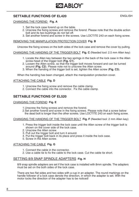
SETTABLE FUNCTIONS OF EL420<br />
CHANGING THE FOREND Fig. A<br />
1. Set the lock case forend up on the table.<br />
2. Unscrew the fixing screws and remove the forend. Please note that the double action<br />
bolt and its two bushings do not fall off.<br />
3. Set another forend and screw in the screws. Use LOCTITE 243 on each fixing screw.<br />
REMOVING THE MANIPULATION PROTECTION COVER Fig. B<br />
Unscrew the fixing screws on the both sides of the lock case and remove the cover by pulling.<br />
CHANGING THE HANDING OF THE TRIGGER BOLT Fig. C (Needed tool: 2.5 mm Allen key)<br />
1. Locate the Allen key between the two springs in the back of the lock case in the Allen<br />
screw-head of the trigger bolt (Fig. C1).<br />
2. Loosen the Allen screw, so that the trigger bolt moves forward and can be turned<br />
around (Fig. C2). Please note not to unscrew the Allen screw.<br />
3. When the handing of the trigger bolt is set, tighten the Allen screw (Fig. C3).<br />
When the handing has been changed, attach the manipulation protection cover.<br />
ATTACHING THE CABLE Fig. D<br />
1. Unscrew the fixing screw and remove the cable clamp.<br />
2. Connect the cable into the connector. Fix the cable clamp.<br />
SETTABLE FUNCTIONS OF EL520<br />
CHANGING THE FOREND Fig. E<br />
1.Unscrew the fixing screws and remove the forend.<br />
2.Set another forend and screw in the fixing screws. Please note that a screw below<br />
the dead bolt is longer than the other screws. Use LOCTITE 243 on each fixing screw.<br />
CHANGING THE HANDING OF THE TRIGGER BOLT Fig. F (Needed tool: 2 mm Allen key)<br />
1. Press the trigger bolt inside the lock case until the Allen screw of the trigger bolt is<br />
shown on the cover side of the lock case.<br />
2. Unscrew the Allen screw.<br />
3. Pull out the trigger bolt and turn it around.<br />
4. Put the trigger bolt back in its place and press it inside the lock case.<br />
5. Screw in the Allen screw.<br />
ATTACHING THE CABLE Fig. G<br />
1. Connect the cable in the connector.<br />
2. Use a cable tie to fix the cable to the lock case. Cut the cable tie short.<br />
SETTING 8/9 SNAP SPINDLE ADAPTERS Fig. H<br />
ENGLISH<br />
8/9 snap spindle adapters are set if the lock case is installed with 8mm spindle. The adapters<br />
must be set on the both sides of the lock case.<br />
There are two flat sides and two sides with a cup in an adapter. The round markings on the<br />
handle follower of a lock case denote the direction, in which the adapter is set. With the<br />
motor locks the direction of the adapter has to be noticed!