

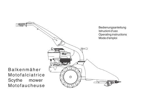
Balkenmäher Motofalciatrice Scythe mower ... - FGM Claymore
Balkenmäher Motofalciatrice Scythe mower ... - FGM Claymore
Balkenmäher Motofalciatrice Scythe mower ... - FGM Claymore

Create successful ePaper yourself
Turn your PDF publications into a flip-book with our unique Google optimized e-Paper software.
<strong>Balkenmäher</strong><br />
<strong>Motofalciatrice</strong><br />
<strong>Scythe</strong> <strong>mower</strong><br />
Motofaucheuse<br />
Bedienungsanleitung<br />
Istruzioni d'uso<br />
Operating instructions<br />
Mode d'emploi
1 2 3<br />
4 5<br />
6
7 8 9<br />
10 11<br />
12
13 14
Inhaltsverzeichnis<br />
Einleitung<br />
Einsatzbedingungen<br />
Sicherheitsmaßnahmen<br />
Bedienungshinweise<br />
Transport<br />
Montage<br />
Einstellung<br />
Wartung<br />
Technische Daten<br />
Lärmemission<br />
Große Gefahr für den<br />
Benutzer und die Personen<br />
in Reichweite der Maschine.<br />
Einleitung<br />
Verehrter Kunde,<br />
Sie haben ein neues Gerät erworben. Wir bedanken uns für Ihr Vertrauen, das Sie in unsere<br />
Qualitätsprodukte setzen und wünschen Ihnen viel Freude beim Arbeiten mit Ihrem neuen Gerät.<br />
Um eine zuverlässige Inbetriebnahme von vornherein zu gewährleisten, haben wir diese Betriebsanleitung<br />
geschaffen. Wenn Sie die folgenden Hinweise genau beachten, wird Ihr Gerät stets zu Ihrer vollsten Zufriedenheit<br />
arbeiten und eine lange Lebensdauer besitzen. Unsere Geräte werden vor der Serienherstellung unter härtesten<br />
Bedingungen erprobt und während der Fertigung selbst ständigen strengen Kontrollen unterzogen. Dies gibt uns<br />
die Sicherheit und Ihnen die Gewähr, stets ein ausgereiftes Produkt zu erhalten. Dieses Gerät wurde im<br />
Herstellerland durch neutrale Prüfstellen nach strengen Arbeits- und Sicherheitsnormen geprüft. Zur<br />
Aufrechterhaltung dieser Funktions- und Sicherheitsgewähr dürfen im Bedarfsfall nur Originalteile des<br />
Herstellers verwendet werden.<br />
Der Benützer verliert alle evtl. bestehenden Ansprüche, wenn er das Gerät mit anderen als den<br />
Originalersatzteilen verändert. Konstruktions-und Ausführungsänderungen vorbehalten. Bei Rückfragen oder<br />
Ersatzteilbestellungen die Artikelnummer und die Erzeugnisnummer angeben.<br />
! ! KENNZEICHNUNGSANGABEN (Abb. 1) Das Schild mit den Maschinendaten und der<br />
Seriennummer befindet sich auf der linken Seite der Maschine, und zwar unter dem Motor. Hinweis- Bei eventuellen<br />
technischen Beratungsfragen oder bei Ersatzteilbestellungen die Kennummer der Maschine angeben.<br />
! ! EINSATZBEDINGUNGEN - EINSATZGRENZEN Der Motormäher ist entwickelt und gebaut<br />
worden, um auf Grasflächen Mäharbeiten auszuführen. Der Motormäher darf nur mit Original-Geräten und Original-<br />
Ersatzteilen arbeiten. Jede Benutzung, die von der hier beschriebenen abweicht, ist nicht gestattet. Es führt nicht<br />
nur zum Verfall der Garantiegewährung, sondern stellt auch eine große Gefahr für den Bediener und alle Personen<br />
in der Reichweite der Maschine dar.<br />
! ! SICHERHEITS-MAßNAHMEN Achtung: Vor der Montage und Inbetriebnahme die<br />
Bedienungsanweisung unbedingt beachten. Personen, die mit der Gebrauchsanweisung nicht vertraut<br />
sind, dürfen das Gerät nicht benützen.<br />
1. Vor dem Mähen müssen Fremdkörper vom Rasen entfernt werden und auch beim Mähen ist auf<br />
Fremdkörper zu achten.<br />
2. Beim Anlassen (Starten) des Motors darf die Bedienungsperson nicht vor dem Mähbalken stehen.<br />
3. Muß der Mäher zum Transport angehoben werden, ist der Motor vorher abzustellen und der Stillstand<br />
des Schneidwerkzeuges unbedingt abzuwarten. Beim Fahren außerhalb des Rasens ist das<br />
Schneidwerkzeug abzuschalten.<br />
DEUTSCH 1
DEUTSCH 2<br />
4. Wartungs- und Reinigungsarbeiten am Mäher dürfen nur bei stillgesetztem Motor und Stillstand des Schneidwerkzeuges erfolgen bzw. bei<br />
abgezogenem Zündkerzendeckel.<br />
5. Beim Verlassen des Mähers ist der Motor stillzusetzen bzw. das Schneidwerkzeug und der Antrieb abzuschalten.<br />
6. Der durch die Führungsholme gegebene Sicherheitsabstand ist stets einzuhalten. Das Bedienen des Mähers ist nur gestattet, wenn der<br />
Führungsholm in Arbeitsstellung befestigt ist.<br />
7. Beim Mähen an Böschungen und Hängen ist besondere Vorsicht geboten.<br />
8. Das Bedienen des Mähers ist Jugendlichen unter 16 Jahren nicht gestattet.<br />
9. Der Bedienende des Mähers hat darauf zu achten daß sich keine weiteren Personen oder Kinder im Arbeitsbereich aufhalten.<br />
10. Bitte beachten Sie die sachgemäße Wartung, die Überprüfung, sowie das Nachschleifen des Messers nach der Bedienungsanleitung.<br />
11. Die Notwendigkeit einer fachmännischen Überprüfung ist erforderlich, wenn z.B. durch Auffahren auf ein Hindernis der Mäher sofort zum<br />
Stehen kommt .<br />
12. Mäher mit Verbrennungsmotor dürfen wegen der damit verbundenen Vergiftungsgefahr keinesfalls in geschlossenen Räumen in Betrieb<br />
genommen werden.<br />
13. Niemals während des Laufens des Motors Kraftstoff nachfüllen. Nicht rauchen beim Auftanken. Verwenden Sie zum Auftanken einen<br />
entsprechenden Trichter, damit kein Kraftstoff auf den Motor und das Gehäuse bzw. auf den Rasen auslaufen kann.<br />
14. Beim Mähen stets feste Schuhe tragen, keine Sandalen oder dergleichen.<br />
Beachten Sie, daß die Verletzungsgefahr für Finger und Füße durch das Schneidwerkzeug bei laufendem Motor sehr groß ist.<br />
15. Nur geeignete Original -Ersatzmesser benützen und die Anweisung “Auswechseln und Nachschleifen des Messers” beachten!<br />
! ! BEDIENUNGSHINWEISE<br />
! ! INSTRUKTIONEN - MOTOR Bitte beachten Sie die Betriebsanleitung des Motorenherstellers. Nach dem Starten: Stellen Sie den<br />
Gashebel langsam in eine Stellung zwischen Start und Stop, wie Ihnen die Drehzahl zum Arbeiten passend erscheint. Mähbalken einschalten. Fahrantrieb<br />
einschalten. Achten Sie beim Mähen auf Fremdkörper und Hindernisse - UNFALLGEFAHR - Beim plötzlichen Auffahren auf ein vorher nicht<br />
sichtbares Hindernis bitte sofort Bedienungshebel in Nullstellung bringen. Mähbalken ausschalten: Nach kurzer Mähzeit den Mäher abstellen und<br />
den festen Sitz aller Schrauben und Muttern überprüfen. Nur mit scharfem Mähmesser und passend eingestelltem Klingenspiel mähen. (siehe<br />
Wartung). Zum Abstellen: Gashebel auf Stop. Mähantrieb auf Stop. Fahrantrieb auf Stop.<br />
! ! TRANSPORT Für den Transport der Maschine ist ein Gabelstapler zu benutzen. Die auf die höchstzulässige Breite gestellten Gabeln sind in den<br />
Raum unter der Palette einzufahren. Das Gewicht der Maschine steht auf dem Typenschild und in den technischen Daten.<br />
! ! MONTAGE DES GASHEBEL-KABELS (Abb. 2) (mit Metallhülle) Den auf dem Motor angeordneten Hebel (1) bis zum Endanschlag,<br />
wie im Bild mit Pfeil “A,’ angegeben. Den auf dem Handholm angeordneten Gasbetätigungshebel (2) bis zum Endanschlag verstellen, wie im Bild mit Pfeil<br />
“B” angegeben. Das Drahtseil (3) in das Loch (4) einführen und die Hülle (5) durch den Halter (6) und Schrauben (7) befestigen. Achtung: Es muss, dass der<br />
Gashebel den Motor auf der Lage “Stop” abstellt.<br />
! ! BOWDENZUG FÜR FAHRANTRIEB (Abb. 3) Der Bowdenzug ist am Gehäuse bereits vormontiert. Er muß nur noch am Bedienhebel
montiert werden. Den Draht (3) und die Stellvorrichtung (4) in das ausgeschnittene Loch der Nase (5) stecken. Hülle (1) in Bohrung (2) einführen.<br />
! ! MONTAGE MÄHBALKEN (Abb. 4) Motor ausschalten ! Bolzen (1) in Bohrung (2) einführen und Keilriemen (3) auf untere Riemenscheibe<br />
legen. Zugfeder (4) in die entsprechenden Haken (5) dann in die Bohrungen (7) einhängen. Abdeckaube aufschrauben. Haube (6) mit Zentrierungs und<br />
Gewindezapfen montieren. Mutter und entsprechende Beilagscheibe auf der Haube anziehen.<br />
! ! BOWDENZUGEINSTELLUNG FÜR MÄHWERK (Abb. 4-5) Wenn der Keilriemen für das Mähwerk durchschleift, Bowdenzug mit<br />
Verstellschraube (2) nachstellen. Das Mähwerk muß zu arbeiten beginnen, wenn die Hälfte des Hebelweges überschritten ist (Abb. 5).<br />
Unterriemenspannung wird wie folgt eingestellt: Mutter (9) unter Scheibe lockern und ein Abstandsstück zwischen den zwei Halbscheiben entfernen (Abb.<br />
4).<br />
! ! EINSTELLEN DER KEILRIEMENSPANNUNG (Abb. 6) Achtung: Die Räder dürfen sich erst drehen, wenn der Bedienungshebel<br />
mehr als die Hälfte gedrückt ist. Bei vollständigem Niederdrücken muß der Hebel (2) die Keilriemenspannung 6-8 mm Verstellweg aufweisen. Verstellweg<br />
der Keilriemenspannung mit Einstellschraube (1) eventuell nachregulieren.<br />
! ! HÖHENVERSTELLUNG DES MÄHBALKENS (Abb. 7) Zur Veränderung der Schnitthöhe werden Gleitschuhe benötigt. Montage<br />
der Gleitschuhe - Mutter (1) lösen. - Gleitschuh (2) in gewünschte Position bringen. - Mutter wieder anziehen.<br />
! ! MESSEREINSTELLUNG (Abb. 8) Durch Verschleiß entstandenes Spiel zwischen Messer und Messerführung, muß die Messerführung<br />
nachgestellt werden. Dazu Kontermutter lösen und mit Sechskantschlüssel VerstelIschraube (1) nachstellen. Nach der Einstellung muß sich das<br />
Mähmesser von Hand frei bewegen lassen.<br />
! ! HÖHENEINSTELLUNG DER LENKHOLME (Abb. 14) Die Schrauben (3) lockern, die Lenkholme auf die gewünschte Höhe einstellen.<br />
Die Schrauben (3) wieder anziehen.<br />
! ! SEITLICHE EINSTELLUNG DER LENKHOLME (Abb. 14) Die Lenkholme können seitlich auf 3 verschiedene Stellungen eingestellt<br />
werden. Dazu folgendermaßen: den Hebel (8) im Gegenuhrzeigersinn drehen, um die Sperre auszuschalten. Die Lenkholme auf die gewünschte Stellung<br />
bringen. Die Lenkholme erneut blockieren, indem man den Hebel (8) im Uhrzeigersinn dreht und sicherstellen, daß die Zähne perfekt eingerastet sind.<br />
! ! WARTUNG Luftfilter Dieser sollte entsprechend der beiliegenden Wartungsanweisung für den Motor gereinigt werden. (spätestens alle 20<br />
Arbeitsstunden)<br />
! ! FAHRGETRIEBE Ölsorte: Getriebeöl SAE 80 Ölstand vor dem Starten überprüfen. Man prüft den Ölstand durch Abschrauben des seitlichen<br />
Getriebeverschlusses. Getriebeöl - Wechsel alle 60 Arbeitsstunden<br />
DEUTSCH 3
DEUTSCH 4<br />
! SCHMIERUNG (Abb. 10) Antrieb für Mähbalken alle 8 Arbeitsstunden an Position (1) mit Fett abschmieren.<br />
! WARTUNG FÜR MÄHBALKEN Der Mähbalken zählt zu den am stärksten beanspruchten Teilen. Es ist deshalb selbstverständlich, daß er mit<br />
besonderer Sorgfalt gewartet und eingestellt werden muß. Es empfiehlt sich, den Mähbalken nach jedem Gebrauch zu reinigen. Dazu ist es erforderlich,<br />
das Mähmesser herauszunehmen, damit vor allen Dingen der zwischen Messerklingen und Fingern bzw. Balkenklingen angesammelte Schmutz gründlich<br />
entfernt werden kann. Wird der Mähbalken längere Zeit nicht benutzt, so sollte er mit einem Rostschutzmittel eingesprüht werden.<br />
Obwohl alle Mähbalkentypen weitgehend unempfindlich gegen den Eintritt von Steinen und ähnlichen Gegenständen sind, kann es gelegentlich<br />
vorkommen, daß Finger bzw. Balkenklingen und Messerklingen beschädigt bzw. verbogen werden. Deshalb ist es ratsam, bei jedem Nachschärfen des<br />
Mähmessers, was je nach Beanspruchung etwa alle 4-6 Betriebsstunden erforderlich ist, auch den Zustand dieser Teile zu überprüfen. Vorhandene<br />
Beschädigungen sind zu beseitigen und verbogene Finger oder Klingen zu richten. Nur gut ausgerichtete Finger und Klingen gewährleisten einen sauberen<br />
Schnitt. Bei dieser Gelegenheit sollte man auch jeweils die Messerführungen überprüfen und zu großes Führungsspiel durch Nachstellen ausgleichen.<br />
! NACHSCHÄRFEN DES MÄHMESSERS (Abb. 11) Je nach Beanspruchung sind die Mähmesser soweit abgestumpft, daß ein<br />
Nachschleifen erforderlich wird. Zu diesem Zweck wird das Mähmesser aus dem Mähbalken herausgenommen und gesäubert. Es ist zu prüfen, ob<br />
Messerrücken und Messerklingen nicht verbogen sind; andernfalls ist ein Nachrichten erforderlich. Erst dann sollte mit dem Nachschärfen begonnen<br />
werden. Zweckmäßigerweise verwendet man hierzu einen Handschleifer mit ca. 15000 - 20000 Umdrehungen pro Minute in Verbindung mit einem<br />
topfförmigen Schleifstift mit einem Durchmesser von 25 mm und einer Länge von ca. 35 mm. Geschliffen wird nur mit der Stirnseite des Schleifstiftes, und<br />
zwar vom Messerrücken zu den Klingenspitzen hin. Messerklingen für Mähbalken benötigen einen Schneidwinkel von 35 - 40°.<br />
! DEMONTAGE DES OBERMESSERS (Abb. 12) Schutzhaube entfernen Befestigungsschrauben (1) ausschrauben. Halter und<br />
Mitnehmerblock entfernen. Einstellschrauben von Messerführungen lösen und Obermesser seitlich herausschieben. Nach mehrmaligem schleifen,<br />
empfiehlt es sich, bei Bedarf, die Messerklingen zu ersetzen. Das Untermesser sowie die Kunststoff - Messerhalter sind dabei auf Verschleiß zu prüfen, und<br />
wenn nötig zu ersetzen.<br />
! BESCHREIBUNG (Abb. 13) 1) Start-Stop, Gashebel - 2) Fahrantrieb, Bedienungshebel - 3) Mähbalkenantrieb, Bedienungshebel - 4) Motor<br />
mit Reversierstarter - 5) Mähbalken - 6) Hebel für seitliches Verstellen der Lenkholme<br />
! TECHNISCHE DATEN Radstand: 430 mm - Mähbalkenlänge: 870 mm - Gesamtlänge: 1350 - Gesamthöhe: 1050 mm - Bereifung: 2 Reifen 4.00-<br />
6 - Masse 60 kg. Weitere techn. Daten u. Hinweise zum Motor: siehe beiliegendes Handbuch des Motorenherstellers.<br />
! LÄRMEMISSION UND VIBRATIONEN Der Wert des Schalldrucks am Arbeitsplatz beträgt gemäß Urkunde N 67 L A e q = 91,4 dB (A).<br />
Vibrationen an den Lenkholmen gemäß Urkunde N 67 und ISO 5349. Meßwert in = 7,8 m/s 2 .
Indice<br />
Introduzione<br />
Condizioni di utilizzazione<br />
Suggerimenti di sicurezza<br />
Istruzioni d' uso<br />
Trasporto<br />
Montaggio<br />
Regolazione<br />
Manutenzione<br />
Dati tecnici<br />
Rumore aereo<br />
Pericolo grave per<br />
l'incolumità dell'operatore e<br />
delle persone esposte.<br />
INTRODUZIONE<br />
Gentile cliente, lei ha acquistato una nuova attrezzatura. La ringraziamo per la fiducia accordata ai ns.<br />
prodotti e le auguriamo un piacevole utilizzo della sua macchina.<br />
Abbiamo creato queste istruzioni per I’uso allo scopo di assicurare, fin dall’inizio, un funzionamento privo d’inconvenienti.<br />
Seguite attentamente questi consigli, avrete la soddisfazione di possedere per molto tempo una macchina<br />
che funziona a dovere.<br />
Le nostre macchine, prima di essere fabbricate in serie, vengono collaudate in maniera molto rigorosa e, durante<br />
la fabbricazione vera e propria, sono sottoposte e severi controlli. Ciò costituisce, per noi e per voi, la migliore garanzia<br />
che si tratta di un prodotto di riprovata qualità.<br />
Questa macchina é stata sottoposta a rigorosi test neutrali, nel paese d’origine, e risponde alle norme<br />
di sicurezza in vigore.<br />
Per garantire questo, é necessario utilizzare esclusivamente ricambi originali.<br />
L’utilizzatore perde ogni diritto di garanzia qualora vengono utilizzati ricambi non originali.<br />
Con riserva di variazioni tecnico-costruttive.<br />
Per informazioni e per ordinazioni di pezzi di ricambio si prega citare il numero di articolo e il numero di produzione.<br />
! DATI PER L'IDENTIFICAZIONE (fig. 1)<br />
L'etichetta con i dati della macchina e il numero di matricola è sul fianco sinistro della motofalce, sotto il motore. Nota<br />
- Nelle eventuali richieste di Assistenza Tecnica o nelle ordinazioni delle Parti di Ricambio, citare sempre il numero<br />
di matricola della motofalce interessata.<br />
! CONDIZIONI DI UTILIZZAZIONE - LIMITI D'USO<br />
La motofalciatrice è progettata e costruita per eseguire operazioni di falciatura di terreni erbosi e deve lavorare<br />
esclusivamente con attrezzi e con ricambi originali. Ogni utilizzo diverso da quello sopra descritto è illegale; comporta,<br />
oltre al decadimento della garanzia, anche un grave pericolo per l'operatore e per le persone esposte.<br />
! NORME DI SICUREZZA<br />
Attenzione: prima del montaggio e la messa in funzione leggere attentamente il libretto istruzione. Le<br />
persone che non conoscono le norme di utilizzazione non possono usare la macchina.<br />
1. Togliere corpi estranei dal prato prima di iniziare le operazioni di falciatura.<br />
2. Nella fase di accensione del motore non sostare nella zona anteriore alle macchina.<br />
3. Per spostare la macchina sulle ruote prima spegnere il motore e attendere I’arresto del dispositivo<br />
di taglio.<br />
ITALIANO 5
ITALIANO 6<br />
4. Tutte le operazioni di pulizia e manutenzione o di montaggio di accessori vanno effettuate a motore spento e con la candela staccata.<br />
5. Abbandonare la macchina solo dopo aver spento il motore e disinserito il dispositivo di sfalcio.<br />
6. Usare la macchina esclusivamente con il manico disposto nella posizione di lavoro. Questo per una completa sicurezza operativa.<br />
7. Lavorando sui pendii, o in prossimità di marciapiedi, usare la macchina con la massima attenzione.<br />
8. L’uso della macchina è vietato ai minori di anni 16.<br />
9. Accertarsi che, durante il lavoro, non sostino estranei nelle immediate vicinanze.<br />
10. Osservate attentamente le istruzioni per l’uso e la manutenzione della macchina e del motore.<br />
11. E’ consigliabile l’intervento di un esperto quando si verifica un blocccaggio della macchina improvviso.<br />
12. Non accendere e far funzionare la macchina in luoghi chiusi. Il motore a scoppio immette gas di scarico pericolosi nell’aria.<br />
13. Non rabbocare il serbatoio durante il funzionamento. Non fumare in presenza del combustibile. Usare solamente carburante ‘’fresco’’.<br />
Riempire il serbatoio per mezzo di un adeguato imbuto.<br />
14. Durante il lavoro vanno indossate calzature robuste per maggior protezione. Fate attenzione che il pericolo di ferirsi le dita o i piedi con la<br />
macchina in funzione è molto elevato.<br />
15. Impiegare solo lame di ricambio originali e seguire attentamente le istruzioni per “la sostituzione e affilatura della lame”.<br />
! ISTRUZIONI D'USO<br />
! ISTRUZIONI MOTORE Leggere attentamente le istruzioni allegate relative al motore Dopo l'avviamento del motore: Portare la leva<br />
acceleratore tra la posizione Start e Stop in modo da raggiungere il regime di giri del motore desiderato. Inserimento barra falciante. Inserimento ruota<br />
motrice. Prestare la massima attenzione se si lavora di ostacoli o con corpi estranei sul prato. - Fonte di pericolo! - In caso di accidentale e di<br />
imprevisto ostacolo bisogna tirare immediatamente la leva di comando, in posizione "0". Arrestare la barra falciante: Dopo un breve periodo di utilizzo<br />
della macchina è utile una verifica del serraggio delle viti e dei bulloni. Falciare esclusivamente con la barra perfettamente affilata. Per spegnere:<br />
Portare la leva comando su posizione STOP.<br />
! TRASPORTO<br />
Per la movimentazione è previsto l'uso di carrello elevatore. Le forche, allargate al massimo consentito, vanno inserite negli appositi spazi del pallet. La massa<br />
della macchina è indicata nella etichetta della marcatura e riportata nei dati tecnici.<br />
! MONTAGGIO MANUBRIO (Fig. 14): Fissare il manubrio (1) al supporto (2) per mezzo delle viti (3). Attenzione: le rondelle con diametro maggiore<br />
devono essere montate in corrispondenza delle asole. Regolare l'altezza del manubrio agendo sulle viti (3) che lo fissano.<br />
! MONTAGGIO CAVO ACCELERATORE (Fig. 2) (con guaina metallica) Posizionare, a fondo corsa, la leva (1) installata sul motore<br />
come indicato dalla freccia “A,, in figura. Portare a fine corsa il manettino comando acceleratore (2) installato sulla stegola come indicato dalla freccia “B,, in<br />
figura. Inserire il cavo (3) nel foro (4), fissare la guaina (5) con l’apposito cavallotto (6) e bloccare con la vite (7). Attenzione: il manettino acceleratore in posizione<br />
“stop’, deve spegnere il motore.<br />
! CAVO COMANDO TENDICINGHIA (Fig. 3) Il cavo di comando è già collegato alla molla tendicinghia e occorre collegarlo alla leva
installata sul manubrio nel modo seguente: inserire il filo (3) e il registro (4) nel foro tagliato del nasello (5); inserire il terminale (1) nel foro (2).<br />
! MONTAGGIO BARRA FALCIANTE (Fig. 4) La motofalce è provvista di un attacco che consente il collegamento facile e rapido della barra<br />
falciante e degli accessori. A motore fermo e con la macchina in posizione orizzontale, inserire per metà il perno della barra (1) nella sua sede (2). Montare la<br />
cinghia (3) sulla puleggia portando in fine corsa il perno guida. Agganciare le molle (4) nei rispettivi ganci (5), poi nei fori (11). Montare il cofano (6) tramite il<br />
perno di centraggio (7). Serrare il dado (8) e relativa rondella sul cofano.<br />
! REGISTRAZIONE DELLA CINGHIA MOVIMENTO BARRA (Fig. 5) Per aumentare la tensione della cinghia del movimento barra<br />
tra macchina e attrezzo, occorre intervenire sul registro (2) in modo che la barra falciante inizi a lavorare solo quando la leva di comando ha superato metà<br />
della propria corsa.<br />
! REGISTRAZIONE DEL COMANDO TENDICINGHIA (Fig. 6) Attenzione - Le ruote devono iniziare a girare solo quando la leva di<br />
comando ha superato la metà della propria corsa. Quando la leva è completamente tirata (posizione di lavoro), la molla di carico del tendicinghia (2) si deve<br />
allungare di circa 6 - 8 mm. Per ottenere le condizioni sopracitate occorre agire sul registro (1) installato nelle vicinanze del comando tendicinghia.<br />
! REGOLAZIONE ALTEZZA BARRA FALCIANTE (Fig. 7) Dovendo falciare su terreni accidentati e necessario regolare l’altezza della<br />
barra falciante. Operare nel modo seguente: - allentare i dadi (1) portare il pattino (2) nella posizione desiderata, serrare i dadi (1). Eseguire l’operazione su<br />
entrambi i pattini.<br />
! REGOLAZIONE DELLA LAMA (Fig. 8) Dopo la sostituzione di una lama o dopo alcune ore di lavoro è necessaria la regolazione del premilama<br />
tramite Ie viti (1 ) e il loro controdado. Per il controllo di ogni regolazione si deve dapprima smontare il cofano, poi fare ruotare Ientamente con<br />
la mano la puleggia (2) e verificare che le lame si muovano liberamente.<br />
! REGOLAZIONE LATERALE DEL MANUBRIO (fig. 14): Il manubrio della motofalciatrice è orientabile sia lateralmente che in altezza. E'<br />
consigliabile, prima di iniziare qualsiasi tipo di lavoro, regolare il manubrio alle esigenze dell'operatore per rendere la motofalciatrice facilmente manovrabile<br />
in ogni movimento. La regolazione laterale del manubrio si può ottenere su 3 diverse posizioni agendo nel modo seguente:<br />
Ruotare in senso antiorario la leva (8) per disinserire il bloccaggio. Regolare il manubrio nella posizione desiderata. Bloccare nuovamente il manubrio<br />
ruotando la leva (8) in senso orario e accertarsi che i denti siano perfettamente innestati.<br />
! MANUTENZlONE Flltro aria: pulirlo regolarmente seguendo le istruzioni concernenti il motore.<br />
! SCATOLA CAMBIO (Fig. 9) Lubrificante - Usare olio SAE 80 Verificare il livello dell’olio prima dell’avviamento del motore. Il livello dell’olio si<br />
verifica posizionando la macchina come in figura e svitando il tappo sul fianco della scatola. Controllare il livello ogni 60 ore di lavoro.<br />
ITALIANO 7
ITALIANO 8<br />
! SEDE ATTACCO ATTREZZO (Fig. 10) Dopo ogni uso pulire ed ingrassare la sede dell'attacco barra falciante tramite l'ingrassatore (1).<br />
! MANUTENZlONE DELLA BARRA FALCIANTE Il tosaerba a barra falciante è certamente una della attrezzature agricole più utilizzate e<br />
richiede pertanto una buona e frequente manutenzione. Si consiglia di pulire a fondo la macchina dopo ogni sfalcio. Per questo é necessario togliere la lama<br />
di taglio in modo da poter ripulire di ogni impurità i denti della barra. Poichè la macchina non viene usata per lunghi periodi è indispensabile proteggere la<br />
barra e lama con sostanze anticorrosive e antiossidanti. Così come per ogni tipo di barra falciante la presenza di impurità o corpi estranei sul prato toglie inevitabilmente<br />
l’affilatura ai denti di taglio. E' utile, pertanto, affilare la lama e controllarne l’integrità dei denti dopo ogni 4 - 6 ore di utilizzo. Solamente con i denti<br />
della lama perfettamente tagliente si puo ottenere il taglio ottimale. E’ utile inoltre un periodico controllo ed eventuale messa a punto del “gioco” della lama nei<br />
supporti di scorrimento. lmportante per una corretta messa a punto dei supporti: Regolare prima uno e poi l’altro supporto. Dopo ogni regolazione del singolo<br />
supporto il ‘’gioco” della lama deve essere verificato muovendo la stessa con la mano.<br />
! AFFlLATURA DELLA LAMA (Fig. 11) In relazione alla intensità di lavoro la lama deve essere periodicamente affilata. A questo scopo la lama<br />
viene rimossa e ben ripulita. Deve essere verificato che i denti e le controlame non siano deformati, dopo di ché si puo procedere all’affilatura.<br />
Generalmente viene utilizzato un affilatore manuale con ca. 15000 - 20000 g/min.’ con punta affilante a testa piena di diametro 25 mm. e lunghezza ca. 35<br />
mm. I denti del la barra necessitano un angolo di affilatura di 35° - 40°.<br />
! SOSTITUZIONE DELLA LAMA FALCIANTE (Fig. 12) Lo smontaggio della lama superiore per l'affilatura o la sostituzione avviene<br />
svitando le viti (1) e sfilando la lama tramite un perno infilato nel foro (2). Dopo 2 o 3 affilature è consigliata la sostituzione della lama. La lama inferiore si consiglia<br />
di sostituirla, in base all'usura, dopo un paio di cambi di quella superiore. Contemporaneamente si sostituiscono i premilama in plastica (3).<br />
! DESCRIZIONE (Fig. 13) 1) Leva comando acceleratore - 2) Leva comando della trasmissione ruote motrici - 3) Leva comando innesto barra - 4)<br />
Motore - 5) Barra falciante - 6) Leva regolazione manubrio laterale.<br />
! DATI TECNICI: Scartamento: 430 mm - Larghezza barra: 870 mm - Lunghezza complessiva: 1500 mm - Altezza: 1000 mm - Pneumatici: 2 gomme<br />
4.00-6 - Massa: 60 kg. MOTORE: Raffreddamento: ad aria. Per altri dati tecnici e particolari del motore, vedere l'allegato manuale di istruzioni dello stesso.<br />
! RUMORE AEREO E VIBRAZIONI Valore di pressione acustica al posto di lavoro secondo documento N 67 L A e q = 91,4 dB (A). Vibrazioni alle<br />
stegole secondo documento N 67 e ISO 5349. Valore rilevato = 7,8 m/s 2 .
Introduction<br />
List of contents<br />
Dear client,<br />
thank you for your confidence in purchasing our equipment. We hope you will spend many enjoyable<br />
Introduction<br />
hours using it. The following working instructions are issued to ensure a reliable use of the machine from the<br />
beginning. If will carefully follow our instructions the machine will correctly operate and have a long service life. The<br />
Conditions of use<br />
machines are tested under the most severe conditions before being put into production and are subjected to strict<br />
continuous tests during manufacturing. We can therefore be sure that you are purchasing a quality product.<br />
Safety measures<br />
The machine has been tested in the country of origin by indipendent testing authorities and in accordance<br />
with strict worknorms and safety standards.<br />
Instructions for operating Only original manufacturer's components should be used to maintain guaranteed function and safety.<br />
The operator will loose any guarantee right if the machine is fitted with non-original spare parts/<br />
Transport<br />
components.<br />
Our machines are subject to design and contructions modifications without notice.<br />
Assembly<br />
For any questions and/or spare parts orders, please inform us about the part and serial numbers.<br />
Regulating<br />
! ! IDENTIFICATION DATA (Fig. 1) The label with machine data and serial number is on the left side of the<br />
Maintenance<br />
motor<strong>mower</strong>, under the engine. Note: in case you need spare parts or/and technical after-sales service, please inform<br />
us about the motor<strong>mower</strong> serial number.<br />
Technichal Data<br />
! ! CONDITIONS AND LIMITATION OF USE This motor<strong>mower</strong> has been designed to perform mowing<br />
Noise<br />
operations on grassy soil and has to be worked only using original equipment and spare parts. Any use other then<br />
those described above is prohibited and will involve the guarantee cancellation and serious risks both for operator<br />
and bystanders.<br />
Serious risk for operator<br />
and bystander safety.<br />
! ! SAFETY PRECAUTIONS Attention: Before assembly and putting into operation, please<br />
read the operating instructions carefully. Persons not familiar with these instructions should not use<br />
the machine.<br />
1. Before you start mowing, the lawn must be cleared of foreign bodies and also during mowing care<br />
must be taken of these foreign bodies.<br />
2. When starting the motor, the person who is handling the machine must not stand in front of the cutter bar.<br />
3. When the rotary <strong>mower</strong> is lifted to be transported, the motor has to be stopped and user has to wait until the<br />
cutting tools come to a standstill. When pushing outside the lawn, the cutting tools are to be stopped.<br />
4. Maintaining and cleaning works and the adjustment of the cutting height are only allowed when the<br />
ENGLISH 9
ENGLISH<br />
10<br />
motor and the cutting tools are stopped or else with the sparking-plug-cap or power-slupply plug drawn off.<br />
5. When leaving the <strong>mower</strong>, the motor must be stopped, or rather the power-supply-plug or ignition key are to be removed.<br />
6. The safety distance given by the guide beams must be observed. The <strong>mower</strong> must only be operated when the guide beam is in a fixed position.<br />
7. Particular attention is necessary when mowing on slopes and declines.<br />
8. Juveniles under 16 years are not allowed to operate the <strong>mower</strong>.<br />
9. The operator of the <strong>mower</strong> must see to it that no other persons are in the working field.<br />
10. Please take care of the appropriate maintenance, checking, and regrinding of the cutter according to the operating instructions.<br />
11. An expert checking is necessary when, for instance, the <strong>mower</strong> comes immediately to a standstill by colliding an obstacle .<br />
12. Rotary <strong>mower</strong>s with an internal combusition engine must in no case be operated in closed rooms because of the poisoning danger.<br />
13. Never refuel with the motor running. Do not smoke when you refuel. Take an appropriate funnel when you refuel so that no petrol can run<br />
over on the motor and the housing or the lawn.<br />
14. When you are mowing always wear solid shoes, no sandals or suchlike. Caution - there is a great risk of injury to fingers and feet when the<br />
motor is running.<br />
15. Please replace with suitable original blades only. Pay attention to instructions how to replace and regrind the blade.<br />
! ! OPERATING INSTRUCTIONS<br />
! ! ! INSTRUCTIONS - ENGINE Please follow the engine manufacturer's operating instructions. After starting: adjust the accelerator lever<br />
slowly into a position between START and STOP which you consider to be suitable operating speed. Swicht on the cutter bar. To swicht on drive<br />
mechanism. DANGER: When mowing beware of foreign bodies and impediments. If you should suddenly run into an unexpected impediment<br />
when mowing, please swicht off operating levers immediately. Stop cutter bar. After mowing for a short time swicht the <strong>mower</strong> off and check if all<br />
nuts and bolts are tight. Only mow with a sharp cutting edge and correct adjustment of all blades. (see maintenance). To stop: Put the accelerator lever<br />
into STOP position.<br />
! ! TRANSPORT A forklift truck should be used to move the machine. The forks should be opened so far as possible and inserted into the pallet. The<br />
weight of the machine is given on the Manufacturer's data plate together with the other technical information.<br />
! ! ! HANDLEBAR ASSEMBLING (Fig. 14) Fix the handlebar (1) to the support (2) using the screws (3). Warning!: the biggest diameter washers<br />
must be assembled corresponding to the holes. Adjust the handlebar height acting on screws (3) which are fixing it.<br />
! ! HOW TO MOUNT THE ACCELERATOR WIRE (Fig. 2) (provided with metal sheath) Position the lever (1) on the engine at the end<br />
of its stroke as shown by arrow "A" in the drawing. Move the throttle lever (2) on the handlebar to the end of its stroke as shown by arrow "B" in the figure. Insert<br />
wire (3) into hole (4), secure the sheath (5) with retainer (6) and screw (7). ATTENTION: in the position "stop" the throttle lever must stop engine.<br />
! ! ! BELT STRETCHER DRIVING WIRE (Fig. 3) The drive wire is already connected to the belt-stretching spring and has to be connected to
the lever on handlebar as follows: insert the wire (3) and the register (4) in the hole cut in the prong (5); insert the sheath terminal (1) into the hole (2).<br />
! ! MOWING BAR ASSEMBLING (Fig. 4) The <strong>mower</strong> is equipped with a quick coupling to allow an easy connection of the mowing bar and<br />
accessories. The engine should be switched off and the machine horizontal: insert halfway the cutter bar pin (1) into its seating (2). Install the belt (3) on the<br />
pulley by moving the guide pin all the way to the end of the motion. Attach the springs (4) to the their hooks (5) into the holes (11). Assemble the hood (6) using<br />
its centering pin (7). Tighten the nut (8) and its washer on the hood.<br />
! ! DRIVE BELT BAR ACTION ADJUSTMENT (Fig. 5) To increase belt tensioning of the bar action between machine and its attachement,<br />
you have to use the register (2) so that the mowing bar could start working only when the control drive lever has already moved more than halfway its travel.<br />
! ! BELT-STRETCHER CONTROL ADJUSTMENT (Fig. 6) Warning! - Tyres should start rotating only when the drive control lever has<br />
moved more than halfway its travel. When the lever is pulled to full extent (working position) the belt-stretcher load spring (2) should extend between 6-8 mm.<br />
to obtain the am conditions you have to act on the nut (1) set close near the belt-stretcher control.<br />
! ! HANDLEBAR HEIGHT ADJUSTMENT (Fig. 7) If you need to mow on rough soil, it is necessary to regulate the height of the mowing bar.<br />
Please act as follows: slacken off screws (1) bring the guide block in the desired position, close the screws (1). Repeat the same operation on both guide blocks.<br />
! ! CUTTING BLADE REGULATION (Fig. 8) After the blade substitution or after some working hours the knife-guide should be regulated by<br />
using means of screws (1) and their locknut. Every time in order to control the regulation you have first to disassemble the hood then slowly make the pulley to<br />
turn (2) and then verify if the blades are easily moving.<br />
! ! HANDLEBAR SIDE ADJUSTMENT (Fig. 14) The <strong>mower</strong> handlebar can be both side and height adjusted. It would be better before starting<br />
to work, to regulate the handlebar according to operator needs in order to make the machine easier to handle in every position. The side handlebar adjustment<br />
can be obtained on 3 different positions: please follow the steps: turn the lever anticlockwise (8) to detatch the clamping regulate the handle in the needed<br />
position. Fix the handlebar again turning the lever (8) clockwise and check that teeth/gears should be fully conncted.<br />
! ! ! MAINTENANCE Air filter: It has to be regularly cleaned following engine instructions.<br />
! ! GEARBOX (Fig. 9) Use SAE 80. Check the oil level before engine starting. The oil level can be controlled positioning the machine as in the drawing<br />
and removing the cap on gearbox side. Please change/check the oil level every 60 working hours.<br />
! ! ATTACHMENT COUPLE (Fig. 10) After use, clean and grease the cutting bar seating with the oil-feeder (1).<br />
ENGLISH 11
ENGLISH<br />
12<br />
! MAINTENANCE OF THE CUTTER BAR The cutting mechanism is one of those pieces of agricultural equipment, which is placed under the<br />
most stress. It is abvious, therefore, that it must be particularly carefully serviced and correctly adjusted. It is advisable to clean the cutting mechanism<br />
after each use. To do this the cutting edge must be removed so that the dirt which has collected between the blades and cutting bars can be completely<br />
removed. Should the cutter bar not be in use for a longer period of time it should be sprayed with an anticorrosive agent. Although all types of bar cutting<br />
mechanism are by and large resistant to the interference of stones and similar objects, it can occasionally happen that the bars and blades become damaged<br />
or bent. It is necessary, therefore, to check the condition of these parts each time you sharpen the cutting blade after 4-6 hours of mowing depending on the<br />
work load. Any damage must be made good and bent gars or blades repaired. Only well aligned bars and blades can guarantee a clean cut. At this point the<br />
track directions of the cutting edges should also be chekked and too much play in the direction be removed by means of adjustment. Important - in order to<br />
obtain a good supports setup, check the first one and then the other. After every regulation of each single support it would be better to verify how the blade<br />
plays moving the same by hand.<br />
! CUTTING BLADE SHARPENING (Fig. 11) When the cutting blade are blunt (this depends on work load) it must be reground. To perform so<br />
the cutting blade is removed from the bar and carefully cleaned. It is necessary to check if both backs and edges of the blades are bent then you can go on with<br />
the sharpening. Suitable to this purpose is a hand grinder with 15000 - 20000 revolutions per minute in conjunction with a cup-shaped grinding point with a 25<br />
mm. diameter and 35 mm. lenght. Cutting bar blades need a cutting angle of 35°-40°.<br />
! CUTTING KNIFE CHANGE (Fig. 12) To remove the top knife to change and sharpen it, remove screws (1) and pull the knife out with a pin push<br />
into hole (2). We recommend changing the knife after 2 or 3 sharpenings. The bottom knife should be changed after the cutting knife should be changed after<br />
a couple of changes of the upper one. In the meantime you have to change the plastic knife guides (3).<br />
! DESCRIPTIONS (Fig. 13) 1) Accelerator operating lever - 2) Drive operating lever - 3) Cutting bar clutching control lever - 4) Engine - 5) Cutting<br />
bar - 6) Lever for the regulation of the side handlebar.<br />
! TECHNICAL INFORMATION Track: 430 mm - Cutting bar lenght: 870 mm - Total lenght: 1500 mm - Height: 1000 mm - Tyres: 2 4.00-6 - Mass: 60<br />
kg. ENGINE: air blast cooling. For further technical details and for the engine, please see the enclosed manual and instructions.<br />
! NOISE AND VIBRATION LEVEL Noise level when working in compliance with document N 67 L A e q = 91,4 dB (A). Handlebar vibration according<br />
to document N 67 and ISO 5349. Level detected = 7,8 m/s 2 .
Table des matières<br />
Introduction<br />
Conditions d'utilisations<br />
Mesures de sécurité<br />
Conseils d'utilisations<br />
Transport<br />
Montage<br />
Réglage<br />
Entretien<br />
Données techniques<br />
Niveau sonore<br />
Danger grave pour<br />
l'intégrité de l'opérateur et<br />
des personnes exposées.<br />
Introduction<br />
Cher client,<br />
Vous venez d’acquérir un nouvel appareil. Nous vous remercions de la confiance que vous nous<br />
témoignez et vous souhaitons beaucoup de satisfaction dans son utilisation.<br />
Afin de garantir d’emblée un fonctionnement sans accrocs nous avons crée cette notice d’utilisation. Si vous<br />
observez exactement les indications suivantes votre appareil fonctionnera toujours à votre entière satisfaction et<br />
restera longtemps utilisable.<br />
Nous appareils avant la fabrication en série, sont mis à I’essai dans les conditions les plus sévères’ et, durant la<br />
fabrication même, sont soumis constamment à des contrôles sévères. De ce fait, nous avons la certitude, et vous la<br />
garantie d’obtenir toujours une machine à toute épreuve.<br />
Cet appareil a été testé et contrôlé par un laboratoire indépendant, selon des normes de travail et de<br />
sécurité très sévères.<br />
Pour garder à cet appareil les qualités et performances prévues, n’utilisez que des pièces détachées<br />
d’origine. La qualité du travail et votre sécurité en dépendent.<br />
L’utilisateur perd tous ses droits à la garantie lorsqu’il modifie l’appareil par l’adjonction de piecès<br />
détachées non d’origine..<br />
Dans le but d’améliorer nos produits’ nous nous réservons le droit d’y apporter des modifications.<br />
Pour toutes questions ou commandes concernant les pieces detachées, prière d’indiquer le numéro de référence.<br />
! ! DONNÉES D'IDENTIFICATION (Fig. 1) L'étiquette avec les données de la machine et le numéro de<br />
matricule se trouve sur le côté gauche de la motofaucheuse, sous le moteur. Note - Fournir le numéro de série de la<br />
motofaucheuse pour toute demande d’assistance technique ou commande de pièces.<br />
! ! CONDITIONS D'UTILISATION - LIMITES D'EMPLOI<br />
La motofaucheuse est projetée et construite pour effectuer des opérations de fauchage. Elle peut travailler<br />
exclusivement avec des outils et des pièces de recharge d'origine. Toute utilisation différente de celle préconisée<br />
est illégale et entraîne l'expiration de la garantie, mais représente aussi un danger grave pour l'opérateur et les<br />
personnes exposées.<br />
! ! MESURES DE SÉCURITÉ<br />
Attention: lire attentivement le manuel d’instructions avant de procéder au montage et à la mise en<br />
marche. La machine ne doit être utilisée que par des personnes connaissant le mode d’emploi.<br />
1. Avant le fauchage, éliminer tous les obstacles qui pourraient gêner en cours de travail.<br />
2. Au démarrage, l’utilisateur ne doit pas se tenir devant la motofaucheuse.<br />
3. Avant de transporter la motofaucheuse, arrêter le moteur et attendre l’arrêt complet de la lame. Pour<br />
un déplacement sur roues, arrêter la lame.<br />
FRANÇAIS 13
FRANÇAIS<br />
4. Toute intervention sur la machine, que ce soit d’entretien, de nettoyage ou de réglage de hauteur, ne doit s’effectuer que moteur coupé; lame<br />
arrêtée et capuchon de la bougie enlevé.<br />
5. Ne jamais quitter l’appareil sans avoir coupé, le moteur et arrêté la traction.<br />
6. La distance imposée pour la conduite par la forme du guidon doit être respectée. L’utilisation de la motofaucheuse n’est autorisée que lorsque le<br />
guidon est en position de travail.<br />
7. Des mesures de sécurité particulières sont à respecter pour faucher le long des buissons et sur les talus.<br />
8. Ne pas autoriser l’utilisation de la motofaucheuse à des adolescents de moins de 16 ans.<br />
9. Veiller à ce qu’aucune personne ne soit présente dans le rayon d’action de la motofaucheuse.<br />
10. Pour l’entretien, la révision et l’affûtage des lames, suivre les conseils de cette notice.<br />
11. L’intervention d’une station-service est nécessaire en cas de choc ayant provoqué I’arrêt subit de la motofaucheuse .<br />
12. En raison des risques d’asphyxie, les motofaucheuses thermiques ne doivent en aucun cas être mises en route dans des locaux mal ventilés.<br />
13. Ne jamais faire le plein pendant la marche. Ne pas fumer en faisant le plein. Pour faire le plein’, utiliser un entonnoir de facon à ne pas verser de<br />
carburant sur le moteur, le carter ou l’herbe.<br />
14. ll est conseillé d’être convenablement chaussé (ni sandales, ni espadrilles). Attention! La lame présente un grand danger pour les mains e t<br />
les pieds.<br />
15. Monter uniquement les lames d’origine. Remplacement et reaffutage de la lame.<br />
! CONSEILS D'UTILISATION<br />
! CONSEILS MOTEUR Pour l'entretien du moteur , respecter les instruction du constructeur. Après le demarrage: Mettre la manette<br />
des gaz sur la position entre Start en Stop qui vous paraît la mieux adaptée au travail. Mise en route de la barre de coupe. Enclenchement de la<br />
traction. Attention! danger. Veiller pendant le travail aux obstacles et corps étrangers. En cas de choc avec un obstacle imprévu, arrêter<br />
immédiatement la traction et la barre de coupe. Arrêter la barre de coupe: Après quelques heures de travail, arrêter la motofaucheuse et resserrer<br />
vis et écrous si nécessaire. Faucher uniquement avec des lames bien aiguisées et correctement ajustées. Ne pas omettre de graisser régulièrement la<br />
barre de coupe. Arrêt: Mettre la manette des gaz sur Stop.<br />
! TRANSPORT Utiliser un chariot élévateur pour transporter la machine. Les fourches, réglées dans la position d'écartement maximum, seront<br />
introduites dans les espaces spécialement prévus de la palette. La masse de la machine est indiquée sur l'etiquette d'identification et reportée dans les<br />
caractéristiques techniques de la machine.<br />
! MONTAGE DU MANCHERON (Fig. 14) Fixer le mancheron (1) au support (2) à travers les vis (3). Attention: les rondelles avec un diamètre<br />
supérieur doivent être assemblées en correspondance avec le trous. Régler la hauteur du mancheron à travers les vis (3) qui le fixent.<br />
! ! MONTAGE DU CABLE DE L’ACCÉLÉRATEUR (Fig. 2) (gaine en métal) Amener le levier (1 ) installé sur le moteur à fin de course<br />
comme indiqué par la flèche “A’, en figure. Amener la manette de gaz (2) installé sur le mancheron à fin de course comme indiqué par la flèche “B,, en figure.<br />
Introduire le câble (3) dans le trou (4), fixer la gaine (5) au moyen du bande (6) et de la vis (7). ATTENTION: il faut que la manette de gaz arrête le moteur dans<br />
14 la position “stop,,.
! CABLE DE COMMANDE TENDEUR DE COURROIE (Fig. 3) Le cable de commande est déjà relié au ressort tendeur de courroie et<br />
il faut le relier au levier installé sur la poignée comme il est indiqué ci-dessous: Introduire le fil (3) et le registre (4) dans le trou coupé de l'ergot (5). Introduire le<br />
borne (1) dans le trou (2).<br />
! BARRE DE COUPE (Fig. 4) La motofaucheuse est équipée d’un attelage qui permet le montage facile et rapide de la barre de coupe et des<br />
accessoires. Le moteur étant arrêté et la machine en position horizontale, introduire jusqu'à moitié l'axe de la barre (1) dans l'emplacement (2). Monter le<br />
curroie (3) sur la poulie en mettant l'axe de guidage en fin de course. Fixer les ressorts (4) dans les crochets respectifs (5) puis dans les trous (11). Monter la<br />
capot (6) au moyen de l'axe de centrage (7). Serrer l'ecrou (8) et la rondelle respective sur le capot.<br />
! RÉGLAGE DE LA COURROIE D'ENTRAÎNEMENT DE LA BARRE (Fig. 5) Pour augmenter la tension de la courroie d'entraînement<br />
de la barre entre la machine et l'outil, il faut agir sur le dispositif de réglage (2) de manière à ce que la barre de coupe commence à travailler uniquement quand<br />
le levier de commande a dépassé la moitié de da course.<br />
! MISE AU POINT DE LA COMMANDE DU TENDEUR DE COURROIE (Fig. 6) Attention - Les roues doivent commencer à<br />
tourner aprés que le levier de commande a dépassé la mi-course. Quand le levier est tout tiré (position de travail) le ressort de charge du tendeur de courroie<br />
( 2) devra s’allonger de 6 à 8 mm environ. Afin d’obtenir les conditions susmentionnées, il faut agir sur l’ecrou (1) installé a proximité de la commande du tendeur<br />
de courroie.<br />
! RÉGLAGE HAUTEUR BARRE COUPEUSE (Fig. 7) Si l’on fauche sur des terrains accidentés il est nécessaire de régler la hauteur de la<br />
barre faucheuse. Effectuer les opérations suivantes: - desserrer l’écrou (1), placer le patin (2) dans la position nécessaire, serrer l’écrou. (1) Effectuer<br />
l’opérations sur les deux patins.<br />
! ! RÉGLAGE DE LA LAME (Fig. 8) Aprés remplacement d’une lame ou aprés quelques heures de travail, il est indispensable de régler les<br />
guidelame au moyen des vis (1) et de l'écrou respectif de blocage. Pour le contrôle de chaque réglage, il faut démonter d’abord le capot et ensulte faire tourner<br />
lentement la poulie (2) à la main pour vérifier que Ies lames bougent librement.<br />
! ! RÉGLAGE LATÉRAL DU MANCHERON (Fig. 14) Le mancheron de la motofacheuse est pivotant soi latéralement que en hauteur. IL est<br />
nécessaire, avant de commençer n'importe quel travail, de règler le mancheron selon les exigences de l'operateur au fin de rendre la motofaucheuse<br />
facilement manoevrable dans chaque mouvement. Le réglage latéral du mancheron peut être obtenu sur 3 positions differentes: tourner le mancheron selon<br />
la position desirée. Bloquer encore le mancheron en tournant la manette (8) en sense horaire et contrôler que les dents soient completement embrayés.<br />
! ENTRETlEN Filtre à air : On doit procéder de temps en temps en suivant les conseils d'entretien figurant dans les instructions du constructeur du<br />
moteur.<br />
! BOÎTE DU CHANGEMENT DE VITESSES (Fig. 9) Lubrifiant - Employer de l’huile SAE 80. Vérifier le niveau de huile avant le<br />
FRANÇAIS 15
FRANÇAIS<br />
16<br />
démarrage. On contrôle le niveau de huile en dévissant le bouchon qui est sur le côte de la boîte. Contrôler le niveau de l’huile tous les 60 heures de travail.<br />
! CHAPE D'ATTELAGE DE L'OUTIL (Fig. 10) Après utilisation nettoyez et graissez la chape (2) à travers le graisseur (1).<br />
! ENTRETIEN DE LA MOTOFAUCHEUSE La barre de coupe est l’un des outils agricoles les plus sollicités. Il est donc évident qu’il faut<br />
l’entretenir et la régler avec un soin particulier. Il est conseillé de nettoyer la motofaucheuse après chaque utilisation. Pour cela, démonter la barre de coupe<br />
afin d’enlever toutes les saletés amassées entre les lames. Si la motofaucheuse ne devait pas servir pendant un certain temps, il faudrait la protéger avec un<br />
produit anti-corrosif et anti-oxydant. Bien que toutes les faucheuses soient conçues pour résister aux cailloux ou autres objets analogues qui se glissent entre<br />
les lames il peut arriver que des lames soient abîmées ou pliées; c’est pourquoi il est conseillé de procéder à une vérification lors du réaffutage de la barre qui<br />
devrait s’effectuer après 4 à 6 heures d’utilisation. Il est nécessaire de changer toutes les lames abimées’ car seule une barre de coupe en parfait état peut<br />
assurer un travail impeccable. Il est conseillé de vérifier par la même le jeu de la lame des guides et en cas de jeu les réajuster. Important - pour une correcte<br />
mise du point des supports d'écoulement: régler avant l'un après l'autre support. Après chaque réglage des chaque support le "jeu" de la lame doit être verifié<br />
eu remuant la même avec la main.<br />
! RÉAFFUTAGE DE LA LAME (Fig. 11) Lorsque les lames sont émoussées, il faut les réaffuter. Retirer les lames et les nettoyer. Vérifier<br />
qu’aucune Partie n’est abimée ou pliée, sinon, procéder au changement de ces parties avant de réaffuter. Utilser une meule-boisseau tournant a 15000 -<br />
20.000 t/mn dont la tige a un Ø de 25 mm et une longueur de 35 mm. N’aiguiser qu’avec la partie frontale de la tige en partant de l’arrière de la lame vers la<br />
pointe. La section de lame doit présenter un angle de coupe de 35 a 40°.<br />
! REMPLECEMENT DE LA LAME DE COUPE (Fig. 12) Lors de l'affûtage ou du remplecement de la lame supérieure, dévisser les vis (1),<br />
pour démonter la lame aprés avoir extrait l'axe du trou (2). Aprés 2 ou 3 affûtage, il est conseillé de remplacement la lame. Remplacer la lame inférieure sur la<br />
base de l'usure, après environ deux remplacement de la lame supérieure. En même temps remplacer les guide-lame en plastique (3).<br />
! DESCRIPTION (Fig. 13) 1) Manette réglage accélérateur - 2) Traction, manette d'entraînement - 3) Levier commande embrayage barre - 4)<br />
Moteur - 5) Barre de coupe - 6) Manette de réglage mancheron latéral.<br />
! DONNÉES TECHNIQUES Voie: 430 mm - Largeur de coupe: 870 mm - Longueur totale: 1500 mm - Hauteur totale: 1000 mm - Pneumatiques: 2<br />
pneus 4.00-6 - Masse: 60 kg. Pour tous renseignements et détails techniques, consulter le manuel d'utilisation ci-joint.<br />
! ! NIVEAU SONORE ET VIBRATION Valeur de pression acoustique au poste de conduite conformément à la norme N 67 L A e q = 91,4 dB (A).<br />
Vibrations des mancherons conformément à la norme N 67 et ISO 5349. Valeur mesurée = 7,8 m/s2 .<br />
32.1065.102 05/01