Bedienungsanleitung PM II Dual Use - Schmidt & Bender
Bedienungsanleitung PM II Dual Use - Schmidt & Bender
Bedienungsanleitung PM II Dual Use - Schmidt & Bender

Create successful ePaper yourself
Turn your PDF publications into a flip-book with our unique Google optimized e-Paper software.
1. Einleitung. . . . . . . . . . . . . . . . . . . . . . . . . . . . . . . . . . . . . . . . . . . . . . . . 2<br />
2. Sicherheitshinweise . . . . . . . . . . . . . . . . . . . . . . . . . . . . . . . . . . . . . . . . 2<br />
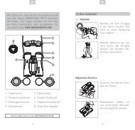
3. Okulareinstellung . . . . . . . . . . . . . . . . . . . . . . . . . . . . . . . . . . . . . . . . . . 2<br />
4. Montage des Zielfernrohres auf die Waffe . . . . . . . . . . . . . . . . . . . . . . . . 2<br />
4.1 Allgemeine Informationen. . . . . . . . . . . . . . . . . . . . . . . . . . . . . . . . . 2<br />
4.2 Verstellweg und Vorneigung . . . . . . . . . . . . . . . . . . . . . . . . . . . . . . . 2<br />
4.3 Vormontage und Feinjustierung. . . . . . . . . . . . . . . . . . . . . . . . . . . . . 3<br />
5. Funktion „double turn“ . . . . . . . . . . . . . . . . . . . . . . . . . . . . . . . . . . . . . 4<br />
6. Funktion „multi turn“. . . . . . . . . . . . . . . . . . . . . . . . . . . . . . . . . . . . . . . 5<br />
7. Funktion „MTC“ . . . . . . . . . . . . . . . . . . . . . . . . . . . . . . . . . . . . . . . . . . . 5<br />
8. Ermitteln der individuellen Kompensationswerte . . . . . . . . . . . . . . . . . . . 5<br />
9. Parallaxeausgleich . . . . . . . . . . . . . . . . . . . . . . . . . . . . . . . . . . . . . . . . . 5<br />
10. Bedienung des Leuchtabsehens . . . . . . . . . . . . . . . . . . . . . . . . . . . . . . . 6<br />
11. Batteriewechsel . . . . . . . . . . . . . . . . . . . . . . . . . . . . . . . . . . . . . . . . . . . 6<br />
12. Wartung und Pflege . . . . . . . . . . . . . . . . . . . . . . . . . . . . . . . . . . . . . . . . 6<br />
13. Abmaßtabelle . . . . . . . . . . . . . . . . . . . . . . . . . . . . . . . . . . . . . . . . . . . 19<br />
14. Technische Daten . . . . . . . . . . . . . . . . . . . . . . . . . . . . . . . . . . . . . . . . . 20<br />
15. Absehendarstellung . . . . . . . . . . . . . . . . . . . . . . . . . . . . . . . . . . . . . . . 22<br />
16. Garantie- und Werksbescheinigung . . . . . . . . . . . . . . . . . . . . . . . . . . . . 39<br />
1<br />
Deutsch
Deutsch<br />
2<br />
1. Einleitung<br />
Zielfernrohre der Modellreihe <strong>PM</strong> <strong>II</strong> wurden für die besonderen Anforderungen<br />
des Präzisionsschießens entwickelt. Sie dienen in Qualität und Funktion sowohl<br />
der Erreichung schießsportlicher Höchstleistungen als auch der Erfüllung dienstlicher,<br />
oftmals ausgesprochen schwieriger und verantwortungs voller Aufgaben.<br />
Die strikte Beachtung nachstehender Gebrauchshinweise ist Voraus setzung für<br />
eine lang jährige erfolgreiche Nutzung.<br />
2. Sicherheitshinweise<br />
Um Augenverletzungen zu vermeiden, blicken Sie niemals mit dem Zielfernrohr<br />
in die Sonne. Unterlassen Sie eigene Eingriffe am Zielfernrohr. Reparaturen sollten<br />
ausschließlich von uns oder durch von uns autorisierte Fachbetriebe durchgeführt<br />
werden. Schützen Sie Ihr Zielfernrohr vor Stößen außerhalb des regulären<br />
Ge brauchs. Vermeiden Sie, das Zielfernrohr unnötig lange direkter Sonnenein<br />
wirkung aus zu setzen; bei hochgradiger und länger andauernder Sonneneinstrahlung<br />
entstehen im Rohrinneren extrem hohe Temperaturen, die dem<br />
Zielfernrohr schaden können.<br />
3. Okulareinstellung<br />
Stellen Sie Ihr Zielfernrohr auf die größtmögliche Vergrößerung ein. Drehen Sie<br />
das Okular bis zum Anschlag nach links und drehen Sie nun so lange nach<br />
rechts, bis Sie das Absehen in optimaler Bildschärfe erkennen (Abb.1).<br />
1<br />
4. Montage des Zielfernrohres auf die Waffe<br />
4.1 Allgemeine Informationen<br />
Waffe und Zielfernrohr müssen durch eine qualifizierte Montage zu einer Einheit<br />
verbunden werden. Wir empfehlen daher, diese Arbeit von einem Fachbetrieb<br />
durchführen zu lassen. Eine perfekte Montage ist unabdingbare Voraussetzung für<br />
einwandfreie Nutzung. Es ist auf korrekten Anschlag und Augenabstand zu achten,<br />
um Augenverletzungen in Folge des Rückstoßes der Waffe zu vermeiden. Für<br />
die Montage des „10 x 42 <strong>PM</strong> <strong>II</strong>“, sowie des „1 - 8 x 24 <strong>PM</strong> ShortDot“/„1,1 - 4 x 20<br />
<strong>PM</strong> ShortDot“/„1,1 - 4 x 24 <strong>PM</strong> ShortDot LE“ und des „1,5 - 6 x 20 <strong>PM</strong> ShortDot“<br />
benötigen Sie Ringe mit 30 mm Durchmesser, für alle anderen <strong>PM</strong> <strong>II</strong>-Modelle<br />
werden 34-mm-Ringe benötigt. Die Montage sollte stabil und generell von guter<br />
Qualität sein. Wir empfehlen, zur Sicherheit die Unterfüße der Montageringe zu<br />
verkleben.<br />
4.2 Verstellweg und Vorneigung<br />
Scharfschützen-Zielfernrohre werden häufig für das Schießen auf große Ent fernungen<br />
verwendet. Dabei wird die Absehen-Höhenverstellung zur Kompen sa tion<br />
der Geschossbahn benutzt. Um bei diesen Zielfernrohren einen noch größeren<br />
Ver stellbereich zu erreichen, hat <strong>Schmidt</strong> & <strong>Bender</strong> den Mittelrohrdurchmesser<br />
einiger Präzisionsschützen-Zielfernrohre für lange Reichweiten von 30 mm auf 34<br />
mm vergrößert. Trotz dem ist auch hier, wie grundsätzlich in jedem Zielfernrohr,<br />
der Höhen- und Sei ten ver stellweg begrenzt.<br />
Um einen gleichmäßigen Verstellweg in alle Richtungen zu erhalten und die<br />
Mon tage zu vereinfachen, wird im Allgemeinen bei den Zielfern-<br />
2<br />
rohren das Absehen auf die optisch-mechanische Mitte ein ge stellt<br />
(siehe Abb. 2).
Um den Höhenverstellweg in vollem Umfang nutzbar zu machen, ist<br />
es bei den <strong>PM</strong> <strong>II</strong>-Modellen unerlässlich, bereits werksseitig das Ab- 3<br />
sehen außerhalb der optisch-me cha nischen Mitte zu justieren (Abb. 3).<br />
Der Büchsenmacher ist deshalb gefordert, den von uns am Zielfernrohr<br />
voreing estellten Wert an der Zielfernrohrmontage anzupassen. Das be- 4<br />
deutet, das Zielfernrohr muss mit ent spre chender Vorneigung auf die<br />
Waffe montiert werden (Abb. 4). Mit dieser Ein stellung kann nun der gesamte<br />
Ver stellweg in einer Richtung genutzt werden. Dies ermöglicht das Schießen, je<br />
nach Kaliber und Ausführung des Zielfernrohres, auf längere Distanzen.<br />
Ermitteln der Vorneigung<br />
Die Vorneigung des Zielfernrohres ist abhängig von den verwendeten Absehen-<br />
Schnellverstellungen. Bei Auslieferung werden die Absehen um die Hälfte des<br />
Gesamtverstellbereiches der Schnellverstellung aus der Mitte gestellt. Dieser<br />
Wert muss bei der Montage ausgeglichen bzw. be rücksichtigt werden.<br />
Im Fachhandel finden Sie für jedes S & B <strong>PM</strong> <strong>II</strong>-Zielfernrohr Montagen bzw.<br />
Montageschienen, die dem jeweiligen Zielfernrohr entsprechend vorgeneigt sind.<br />
Rechenbeispiel zur Bestimmung der Vorneigung<br />
Die von uns in der Standardausführung ausgelieferte Stellkappe mit 13 mrad<br />
oder 130 cm Verstellweg auf 100 m benötigt eine Vorneigung von 65 cm/100 m<br />
(entspricht dem halben Verstellbereich). Wenn der Büchsenmacher nun die Vorneigung<br />
über die Montage einstellt, kann folgender Richtwert gelten: Beträgt<br />
der Abstand der Montageringe 100 mm zueinander, sollte der vordere Fuß etwa<br />
0,65 mm niedriger sein als der hintere.<br />
Verwendet der Büchsenmacher eine dem jeweiligen Zielfernrohr entsprechende<br />
vorgeneigte Montageschiene, können auch herkömmliche Montageringe verwendet<br />
werden.<br />
4.3 Vormontage und Feinjustierung<br />
Stellen Sie zunächst sicher, dass beide Stellkappen auf -0- eingestellt sind. Bei<br />
den Stellkappen mit „double turn“-Verstellung achten Sie zusätzlich<br />
darauf, dass die schwarzen Sichtfenster angezeigt werden (Abb. 5). 5<br />
Bei den Stellkappen „multi turn“ muß die Zahl -1- (Abb. 6) im Sichtfenster<br />
zu sehen sein. Das Zielfernrohr wird nun montiert und mittels<br />
aller an der Montage ge gebenen Korrekturmöglichkeiten so genau auf 6<br />
ein 100 m entferntes Ziel aus ge richtet, dass bei der Feinjustierung während<br />
des Einschießens am Zielfernrohr möglichst wenig Verstellweg verbraucht<br />
wird. Vor dem Einschießen lösen Sie die beiden Inbus schrauben 7<br />
in den Stellkappen der Höhen- und Seiten verstellung (Abb. 7), heben<br />
die Stellkappe so weit an, dass der schwarze O-Ring sichtbar wird, und<br />
ziehen die beiden Inbusschrauben vorsichtig handfest wieder an (Abb. 8<br />
8). Zur Feinjustierung können die Stellkappen jetzt in beide Richtungen<br />
gedreht werden.<br />
Mit jedem Klick wird das Absehen um den auf der Stellkappe fest gelegten Wert<br />
verstellt. Einen Tiefschuss korrigieren Sie durch Drehung der Höhenstellkappe<br />
im Uhrzeigersinn (nach rechts, Abb. 9); einen Hochschuss durch 9<br />
Drehung entgegen dem Uhrzeigersinn (nach links).<br />
3<br />
Deutsch
Deutsch<br />
4<br />
10<br />
Einen Linksschuss korrigieren Sie durch Drehung der Seitenstellkappe<br />
im Uhrzeigersinn (nach rechts, Abb. 10), einen Rechtsschuss durch<br />
Drehung entgegen dem Uhrzeigersinn (nach links).<br />
Achtung: Für die Versionen CCW (counter-clock-wise / gegen den Uhrzeigersinn)<br />
sind die Korrekturen selbstver ständlich entgegengesetzt.<br />
11<br />
12<br />
13<br />
Nach dem Einschießen lösen Sie die beiden Inbusschrauben in den Stellkappen<br />
(Abb. 11). Anschließend stellen Sie die Höhen- und Seitenverstellung<br />
wieder auf -0- korrespondierend mit dem Indexdreieck an der<br />
jeweiligen Position am Rohrkörper. Die Abseheneinstellung darf dabei<br />
nicht verändert werden. Drücken Sie die Stellkappen jetzt vollständig<br />
nach unten (Abb. 12) und ziehen Sie die Inbusschrauben wieder fest<br />
an (Abb. 13).<br />
Bei den Stellkappen mit „double turn“-Verstellung beachten Sie bitte,<br />
dass sich die Farbe im Anzeigefenster nicht verändert hat. Hier müssen<br />
5 noch immer die schwarzen Sichtfenster erkennbar sein (Abb. 5). Sollte<br />
sich diese Einstellung verstellt haben, gehen Sie wie folgt vor: Inbus-<br />
14 schrauben lösen und Kappe abnehmen. Stellen Sie den Pendelzylinder<br />
(Abb. 14), ggf. mit Hilfe eines Schraubendrehers, wieder in seine Ausgangsstellung<br />
zurück. Setzen Sie die Stellkappe wieder, wie oben beschrieben,<br />
auf das Zielfernrohr auf.<br />
Bei den Stellkappen „multi turn“ muß noch immer die Zahl -1- (Abb. 6) im<br />
Sichtfenster zu sehen sein. Sollte das nicht der Fall sein, gehen Sie wie<br />
6 folgt vor: Inbusschrauben lösen und Kappe abnehmen. Stellen Sie den<br />
Pendelzylinder (Abb. 15), ggf. mit Hilfe eines Schraubendrehers, wieder<br />
in seine Ausgangsstellung zurück. Setzen Sie die Stellkappe wieder, wie<br />
oben beschrieben, auf das Zielfernrohr auf.<br />
15<br />
5. Funktion „double turn“<br />
Die „double turn“-Version unserer Stellkappen ermöglicht eine feine Klick rastung<br />
unter Beibehaltung des großen Verstellweges. Anstatt einer Umdrehung lässt sich<br />
die „double turn“-Verstellung, wie schon aus ihrem Namen zu entnehmen, zwei<br />
Umdrehungen verstellen. Wie im Kapitel „Vormontage und Feinjustieren beim<br />
Einschießen“ beschrieben, wird die Stellkappe einmal eingeschossen und auf die<br />
Nullposition aufgesetzt. Von dieser Stellung aus kann man den großen Verstellbereich<br />
der „double turn“-Verstellung nutzen. Befindet man sich in der ersten<br />
Umdrehung, bleiben die Sichtfenster oberhalb der Stellkappe schwarz<br />
5<br />
16<br />
(Abb. 5) und zeigen dem Schützen an, dass er seine Einstellung auf der<br />
unteren Skala ablesen muss. Dreht man die Stellkappe in die zweite<br />
Umdrehung, werden die Sichtfenster gelb (Abb. 16). Sie zeigen deutlich<br />
an, dass man sich in der zweiten Umdrehung befindet und jetzt die Einstellung<br />
auf der oberen gelben Skala ab zulesen ist. Mit dieser „double<br />
turn“-Verstellung erkennen Sie selbst bei un günstigen Licht verhältnissen sofort,<br />
in welcher Umdrehung Sie sich befinden und somit auch welchen Einstellungswert<br />
Sie gewählt haben.
6. Funktion „multi turn“<br />
Die „multi turn“ Version unserer Stellkappen ermöglicht eine feine Klickrastung<br />
unter Beibehaltung des großen Verstellweges. Anstatt einer Umdrehung lässt<br />
sich die „multi turn“-Verstellung insgesamt fünf Umdrehungen verstellen. Wie<br />
im Kapitel „Vormontage und Feinjustieren beim Einschießen“ beschrieben, wird<br />
die Stellkappe einmal eingeschossen und auf die Nullposition aufgesetzt. Von<br />
dieser Stellung aus kann man nun den großen Verstellbereich der „multi<br />
turn“- Verstellung nutzen. Befindet man sich in der ersten Umdrehung<br />
(Abb. 6) bleibt in den Sichtfenster oberhalb der Stellkappe die Zahl -1- zu<br />
sehen. Dreht man weiter in die zweite Umdrehung, erscheint im Sichtfenster<br />
die Zahl -2-. Die zweite Umdrehung beginnt mit dem Verstellwert,<br />
der über der Null steht. Die zwei gravierten Punkte neben dieser<br />
Zahl zeigen Ihnen an, dass Sie sich in der zweiten Umdrehung befinden. Das<br />
gleiche gilt, wenn Sie weiter drehen für die 3., 4. und 5. Umdrehung (Abb. 17).<br />
7. Funktion „MTC“ (More Tactile Clicks)*<br />
Verstelltürme mit der optionalen Funktion „MTC“ (<strong>Schmidt</strong> & <strong>Bender</strong>, U.S. Patent<br />
# 7.612.952) haben an der Höhen- und Seitenverstellung alle 10 Klicks eine<br />
stärkere Rastung.<br />
Bei verschiedenen Modellen ist nur die Null-Rastung der Seitenverstellung<br />
stärker ausgeprägt.<br />
8. Ermitteln der individuellen Kompensationswerte<br />
Durch Schießen auf die entsprechenden Entfernungen und Eintragen der jeweiligen<br />
Rastwerte in eine Tabelle können Sie nun Ihre individuelle Ge schossbahn<br />
kompensa tion selbst erstellen. Gegenüber der zum Teil üblichen „Vorabfestlegung“<br />
in Form kalibrierter Stellkappen, die auf Entfernungstabellen der<br />
Munitionshersteller basieren, hat diese Vorgehensweise den großen Vorteil,<br />
dass die vielfältigen Einflüsse, die sich von der Waffe über die Montage bis zur<br />
verwen deten Munition auf die Flugbahn des Geschosses auswirken können, berücksichtigt<br />
sind.<br />
9. Parallaxeausgleich<br />
Die <strong>PM</strong> <strong>II</strong>-Modelle ohne Parallaxeausgleich werden werksseitig auf 300 m<br />
parallaxe frei justiert, sofern bei der Bestellung keine abweichende Distanz angegeben<br />
wird.<br />
<strong>PM</strong> <strong>II</strong>-Zielfernrohre mit Parallaxeausgleich verfügen über ein Stellrad<br />
(Abb. 18) welches leicht bedienbar als dritter Turm gegenüber der Seitenverstellung<br />
angeordnet ist. Damit kann der Schütze individuell die Parallaxe<br />
seines Zielfernrohres justieren, ohne die Zielerfassung unterbrechen zu müssen.<br />
Der Stellring des Parallaxeausgleichs ist mit den Entfernungen beschriftet. Bei bekannter<br />
Entfernung drehen Sie den Stellring so, dass die angestrebte Ent fernung<br />
mit dem Indexring am Sattel zur Deckung kommt.<br />
Wenn die Entfernung nicht bekannt ist, stellen Sie die maximale Vergrößerung<br />
ein. Bewegen Sie danach den Stellring des Parallaxenausgleichs so lange in Richtung<br />
der von Ihnen geschätzten Entfernung, bis Sie ein scharfes Bild eingestellt<br />
haben.<br />
Die Parallaxe ist nun korrekt justiert und Sie können außerdem die Entfernung<br />
am Stellknopf ablesen.<br />
*„lizensiert von U.S. Optics, U.S. Patent # 7,415,791“<br />
6<br />
17<br />
18<br />
5<br />
Deutsch
Deutsch<br />
6<br />
10. Bedienung des Leuchtabsehens<br />
Das Leuchtabsehen soll Ihnen helfen, bei schlechten Lichtverhältnissen Ihren<br />
Haltepunkt auf dem häufig dunklen Ziel besser zu finden.<br />
Passen Sie zunächst die Intensität der Absehenbeleuchtung den jeweilige Lichtverhältnissen<br />
an. Dazu drehen Sie den Stellknopf der Leuchteinheit von -0- in<br />
Richtung -11- bis zu der Stufe, in der die Leuchtfigur innerhalb des Absehens<br />
gerade ausreichend beleuchtet ist, ohne Ihre Augenpupille zu überstrahlen. Diese<br />
Einstellung sollten Sie möglichst in Ruhe vor der eigentlichen Aktion vornehmen.<br />
Sie können jetzt stromsparend die Leuchteinheit ausschalten, indem Sie den<br />
Stellknopf aus der eingerasteten Stufe heraus zwischen die vor- oder nachgelagerte<br />
Stufe einstellen (Abb. 19). In dieser „Zwischen position“<br />
19 ist die Strom zufuhr unterbrochen (Stand-by-Modus). Unmittelbar vor<br />
der Schussabgabe genügt ein kurzes Einrasten in die vorher ausgewählte<br />
Stufe und Ihr Absehen leuchtet genau in der passenden Intensität.<br />
Versäumen Sie bitte nicht, nach dem Schuss Ihr Leuchtabsehen wieder auszuschalten.<br />
Sollte Ihnen dies trotzdem passieren, schaltet ein eingebauter Microchip<br />
die Be leuchtung nach 6 h automatisch ab.<br />
11. Batteriewechsel<br />
Zum Batteriewechsel lösen Sie den Schraubendeckel der Leuchteinheit.<br />
Entnehmen Sie die verbrauchte Batterie, die Sie unbedingt umweltgerecht<br />
entsorgen sollten. Achten Sie beim Einlegen der neuen Batterie<br />
20<br />
darauf, dass das Pluszeichen auf der Batterie oben erkennbar ist. Der<br />
Batteriewechsel muss im Trockenen stattfinden. Es handelt sich bei der<br />
Batterie um eine handelsübliche Knopfzelle CR2032/3V, die bei höchster Intensität<br />
im Dauer betrieb ca. 100 Stunden Energie liefert (Abb. 20).<br />
12. Wartung und Pflege<br />
Die <strong>Schmidt</strong> & <strong>Bender</strong> Zielfernrohre der <strong>PM</strong> <strong>II</strong>-Modellreihe benötigen keine be-<br />
son de re Wartung und Pflege.<br />
Alle Metallteile sind mit einer harten Eloxal-Oberfläche versehen, die grundsätzlich<br />
pflegeleicht und extrem kratzfest ist. Zur Reinigung verwenden Sie hier<br />
ein sauberes und ggf. leicht angefeuchtetes Putztuch.<br />
Zur Reinigung der Optik benutzen Sie bitte das von <strong>Schmidt</strong> & <strong>Bender</strong> beige fügte<br />
Reinigungsset. Optikoberflächen sollten Sie vor einem evtl. Sauberwischen zunächst<br />
mit dem Pinsel von grobem Staub und Schmutzpartikeln befreien. Leichte<br />
Verschmutzungen können dann mit dem Optik-Reinigungstuch entfernt werden.<br />
Hauchen Sie die Optik vor dem Reinigen leicht an, dies erleichtert den Reinigungs<br />
vorgang mit dem Optiktuch. Grobe Verschmutzungen können mit der im<br />
Reinigungsset befindlichen Reinigungsflüssigkeit entfernt werden.<br />
Trockenes Reiben auf den Außenflächen der Linsen müssen Sie auf jeden Fall<br />
vermeiden, dies kann die wertvolle Vergütungsschicht zerstören.
1. Introduction . . . . . . . . . . . . . . . . . . . . . . . . . . . . . . . . . . . . . . . . . . . . . . 8<br />
2. Safety instructions . . . . . . . . . . . . . . . . . . . . . . . . . . . . . . . . . . . . . . . . . 8<br />
3. Adjusting the image focus with the diopter adjustment of the eyepiece . . 8<br />
4. Mounting the scope to a firearm . . . . . . . . . . . . . . . . . . . . . . . . . . . . . . . 8<br />
4.1 General information . . . . . . . . . . . . . . . . . . . . . . . . . . . . . . . . . . . . . 8<br />
4.2 Adjustment range and forward angle. . . . . . . . . . . . . . . . . . . . . . . . . 8<br />
4.3 Preliminary adjusting and fine adjusting when sighting in . . . . . . . . . 9<br />
5. Function of the „double turn“ turret . . . . . . . . . . . . . . . . . . . . . . . . . . . 10<br />
6. Function of the „multi turn“ turret . . . . . . . . . . . . . . . . . . . . . . . . . . . . 10<br />
7. Function of the „MTC“ turret . . . . . . . . . . . . . . . . . . . . . . . . . . . . . . . . . 11<br />
8. Determining individual values for bullet drop compensation. . . . . . . . . . 11<br />
9. Parallax adjustment . . . . . . . . . . . . . . . . . . . . . . . . . . . . . . . . . . . . . . . 11<br />
10. Using the illumination control . . . . . . . . . . . . . . . . . . . . . . . . . . . . . . . . 11<br />
11. Changing the battery . . . . . . . . . . . . . . . . . . . . . . . . . . . . . . . . . . . . . . 12<br />
12. Maintenance . . . . . . . . . . . . . . . . . . . . . . . . . . . . . . . . . . . . . . . . . . . . 12<br />
13. Dimensions of <strong>PM</strong> <strong>II</strong> scopes . . . . . . . . . . . . . . . . . . . . . . . . . . . . . . . . . . 19<br />
14. Technical data . . . . . . . . . . . . . . . . . . . . . . . . . . . . . . . . . . . . . . . . . . . 20<br />
15. Reticles . . . . . . . . . . . . . . . . . . . . . . . . . . . . . . . . . . . . . . . . . . . . . . . . 22<br />
16. Warranty Certificate . . . . . . . . . . . . . . . . . . . . . . . . . . . . . . . . . . . . . . . 40<br />
7<br />
English
English<br />
8<br />
1. Introduction<br />
The scopes of the <strong>Schmidt</strong> & <strong>Bender</strong> <strong>PM</strong> <strong>II</strong> series are designed to meet the unique<br />
challenges of high precision shooting. Their quality and function make it possible<br />
to achieve exceptional shooting results as well as to fulfill the critical and demanding<br />
needs of official, law enforcement and tactical applications.<br />
Strict observation of the following operating instructions is prerequisite for<br />
successful long-term use.<br />
2. Safety instructions<br />
Never look into the sun with the scope. This may cause serious eye injuries. To<br />
avoid injuries always keep the correct eye relief distance when shooting. Do<br />
not tamper with the scope. Any repairs going further than the maintenance<br />
described in the maintenance manual should only be done by <strong>Schmidt</strong> & <strong>Bender</strong><br />
or by other specialists authorized by <strong>Schmidt</strong> & <strong>Bender</strong>. Protect the scope against<br />
shocks beyond normal use.<br />
Avoid unnecessarily long exposure of the scope to direct sunlight; intense and<br />
excessive sun radiation will cause extremely high temperatures inside the tube<br />
which may be detrimental to the scope.<br />
3. Adjusting the image focus with the diopter adjustment of the eyepiece<br />
Set the scope to the highest magnification. Rotate the eyepiece counterclockwise<br />
to its stop. Rotate the eyepiece clockwise until you see a sharp image of<br />
the reticle (see illus. 1).<br />
1<br />
4. Mounting the scope to a firearm<br />
4.1. General information<br />
The firearm and the scope must be united by proper mounting. Therefore we<br />
recommend to get this done by a qualified specialist. Perfect mounting is an<br />
essential requirement for maximum accuracy and an efficient functioning of the<br />
firearm and the scope.<br />
Be sure to assume the proper firing position and keep a correct eye relief in order<br />
to avoid any injuries due to the recoil of the weapon. To mount the 10 x 42 <strong>PM</strong> <strong>II</strong>,<br />
the 1 - 8 x 24 <strong>PM</strong> ShortDot, the 1.1 - 4 x 20 <strong>PM</strong> ShortDot, the 1.1 - 4 x 24 <strong>PM</strong> ShortDot<br />
LE and the 1.5 - 6 x 20 <strong>PM</strong> ShortDot scope you need rings with a 30 mm diameter.<br />
All other <strong>PM</strong> <strong>II</strong> scopes will require 34 mm rings. The mount should be rugged and<br />
of good quality. For safety reasons we recommend that the lower part of the<br />
rings should be glued.<br />
4.2. Adjustment range and forward angle<br />
Scopes for high precision shooting are often used for shooting at great distances.<br />
In this case the elevation adjustment is used to compensate for bullet drop.<br />
To obtain an even greater adjustment range on these scopes, <strong>Schmidt</strong> & <strong>Bender</strong><br />
increased the diameter of the center tube on a number of precision scopes for<br />
long distances from 30 to 34 mm. Nevertheless, elevation and windage ranges<br />
are limited like in any other scope.<br />
2<br />
To get a consistent adjusting range in every direction and to simplify the<br />
mounting procedure, the reticle on the scopes is usually set to the optical<br />
and mechanical center position (see illus. 2).
To be able to use the complete elevation adjustment on the <strong>PM</strong> <strong>II</strong> scopes<br />
it is absolutely necessary to realize a default adjustment on the reticle 3<br />
outside the optical and mechanical center position (illus. 3). Therefore<br />
the gunsmith is forced to adjust the default value during scope mounting,<br />
i.e. the scope should be mounted on the firearm using the proper 4<br />
forward angle (illus. 4). Using this setting the entire adjustment range<br />
may be used in one direction. Thus, depending on caliber and scope design, you<br />
may shoot the weapon at greater distances.<br />
Determining the proper forward angle<br />
The necessary forward angle is depending on the used type of elevation adjustment.<br />
At the <strong>Schmidt</strong> & <strong>Bender</strong> factory the reticles of <strong>PM</strong> <strong>II</strong> scopes are adjusted<br />
out of center by half the amount of the full elevation range. This value must be<br />
compensated in the mount system. Forward angled mounts or rails for every<br />
<strong>Schmidt</strong> & <strong>Bender</strong> <strong>PM</strong> <strong>II</strong> scope type are available from all renowned mount manufacturers.<br />
Example for determining the required forward angle<br />
A standard elevation turret (single turn) with an elevation range of 13 mrad<br />
(equals 130 cm at 100 m distance) requires a forward angle of 65 cm at 100 m<br />
(equaling half the full elevation range). A gunsmith compensating for this value<br />
using the mounts should observe the following rule of thumb: If the space between<br />
the two mount rings is 100 mm, the front mount should be 0.65 mm lower<br />
than the rear mount.<br />
If the gunsmith is using a rail with forward angle, he may use standard mount<br />
rings without forward angle.<br />
4.3. Preliminary adjusting and fine adjusting when sighting in<br />
Make sure that both elevation and windage are set to -0-. If the scope<br />
is equipped with a „double turn“ elevation turret, the windows on top<br />
of the turret must show black (see illus. 5). The „multi turn“ turret has<br />
to show -1- (illus. 6). Mount the scope to the firearm and pre-adjust the<br />
scope to a target at 100 m distance using all adjustment facilities the<br />
mounts provide so that the least possible amount of elevation range<br />
must be used at the scope for fine adjustment. Before sighting in unlock<br />
the two setscrews in the outside diameter of both elevation an windage<br />
turret using an Allen key (see illus. 7). Lift each turret cap until the black<br />
o-ring underneath is visible. Lock the setscrews again (see illus. 8). The<br />
turret caps may not be adjusted in all directions for fine adjustment.<br />
With every click the reticle will travel by the amount indicated on the turret cap.<br />
A too low point of impact is corrected by rotating the elevation turret<br />
clockwise (see illus. 9), a too high point of impact by rotating the eleva- 9<br />
tion turret counter-clockwise.<br />
A too far left point of impact is corrected by rotating the windage turret<br />
clockwise (see illus. 10), a too far right point of impact is corrected by<br />
rotating the turret counter-clockwise.<br />
Attention: for counter-clockwise elevation and windage versions the corrections<br />
for point of impact must be effected in the opposite directions!<br />
5<br />
6<br />
7<br />
8<br />
10<br />
9<br />
English
English<br />
10<br />
11<br />
12<br />
13<br />
After sighting in, loosen the two Allen screws inside the turrets (illus.<br />
11). Then reset elevation and windage adjustments to -0-, corresponding<br />
to the indexing triangle on the respective tube position. Make sure<br />
the turrets do not rotate (and change the position of the reticle) while<br />
doing this. Press the turret caps completely down (see illus. 12) and lock<br />
the setscrews again (see illus. 13).<br />
When the scope is equipped with a „double turn“ elevation turret make<br />
sure that the color in the windows on top of the turret cap is still show-<br />
5 ing black (see illus. 5). If the color changed to yellow proceed as follows:<br />
unlock the setscrews in the outside diameter of the „double turn“ turret<br />
14 again, pull the turret cap up and take it off completely. Position the slotted<br />
steel cylinder (see illus. 14) inside the turret cap in its final position<br />
(a screw driver or similar tool may be used to rotate the cylinder). Choose the<br />
position providing for the windows on top of the turret cap to show black. Now<br />
place the turret cap on the elevation turret again as described before.<br />
6<br />
15<br />
The „multi-turn“ turrets should still show -1- (illus. 6). If not, proceed<br />
as follows: loosen Allen screws and remove turret cap. Now return the<br />
pendular cylinder (illus. 15) using a screwdriver, if necessary, to its basic<br />
position. Now put the turret cap back on the scope as described above.<br />
5. Function of the „double turn“ turret<br />
The „double turn“ elevation provides a fine click adjustment value with a big<br />
elevation adjustment range at the same time. Instead of having only one revolution<br />
for the full elevation range the „double turn“ turret – as the name<br />
implies – uses two revolutions for the full elevation range. As described in the<br />
chapter „preliminary adjusting and fine adjusting when sighting in“ the elevation<br />
gets sighted in and is thus set to -0-. Starting from this position you may<br />
use the complete elevation range. If elevation is set to a position within the first<br />
revolution, the windows on top of the turret cap show black (see illus.<br />
5<br />
16<br />
5) indicating the shooter must refer to the lower scale on the turret cap.<br />
If the turret is rotated into the second revolution the windows change<br />
their color to yellow (see illus. 16), clearly indicating that elevation is<br />
in the second revolution and the shooter now must refer to the yellow<br />
scale. Even in poor light conditions the shooter may easily recognize in<br />
which revolution the turret is set at every given time and thus to what value the<br />
elevation is set.<br />
6. „Multi turn“ function<br />
The „multi turn“ version of our turrets permits a fine click lock adjustment while<br />
keeping a wide adjustment range at the same time. Instead of only one turn the<br />
„multi turn“ feature may achieve a total of five turns. As we described in chapter<br />
„preliminary adjusting and fine adjusting when sighting“, the turret is sighted in<br />
once and set on top of the zero position. Starting from this position the shooter<br />
may now use the large adjustment range of the „multi turn“ function.<br />
6<br />
If you find yourself in the first rotation (illus. 6), -1- is displayed in the<br />
windows on top of the turret. If you proceed and rotate to the second
otation, -2- will appear. The second rotation starts with the adjustment above<br />
zero. The two engraved dots beside this number indicate that you find<br />
yourself in the second rotation. The same applies for the 3rd , 4th and 5th 17<br />
rotation (illus. 17).<br />
7. „MTC“ Function (More Tactile Clicks)*<br />
Turrets featuring the optional „MTC“ (<strong>Schmidt</strong> & <strong>Bender</strong>, U.S. Patent # 7.612.952)<br />
function have a stronger lock on every 10 clicks on the elevation and windage<br />
adjustment.<br />
Various other models only have a stronger lock on the windage zero position.<br />
8. Determining individual values for bullet drop compensation<br />
By shooting at varying distances and recording the corresponding click values in<br />
a table you can make your own individual bullet drop compensation charts. In<br />
contrast to the common technique of calibrating adjustment turrets to „predetermined“<br />
trajectory tables provided by ammunition manufacturers our recommended<br />
procedure takes all factors into account that have a influence on bullet<br />
drop – firearm, mount and used ammunition. This will result in extremely precise<br />
bullet drop tables created specifically for your firearm.<br />
9. Parallax adjustment<br />
All <strong>PM</strong> <strong>II</strong> models without parallax adjustment are preset at the <strong>Schmidt</strong> & <strong>Bender</strong><br />
factory to be parallax-free at 300 m unless a different distance is specified.<br />
<strong>PM</strong> <strong>II</strong> scopes with parallax compensation have an easily operable setting wheel<br />
(illus. 18), positioned as a third turret opposite the windage adjustment.<br />
With this turret the shooter may easily focus targets at any distance 18<br />
without having to interrupt his target acquisition.<br />
The parallax adjustment turret is engraved with distance markings. If the distance<br />
to the target is known rotate the turret so that the corresponding distance marking<br />
lines up with the index mark on the saddle.<br />
If the distance to the target is not known set the scope to the highest magnification.<br />
Then move the adjustment ring of the parallax compensation in the<br />
direction of the estimated distance until you get a focused image.<br />
Not he parallax has been properly adjusted and you may also read the distance<br />
on the turret.<br />
* licenced by U.S. Optics, U.S. Patent # 7.415.791<br />
11<br />
English
English<br />
12<br />
10. Using the illumination control<br />
The illuminated reticle is designed to help identifying the correct aiming point on<br />
a dark target and/or in poor light conditions.<br />
First, set the intensity of the illuminated reticle to the respective light conditions.<br />
To do this the illumination control may be turned from -0- toward position -11until<br />
a setting is achieved where the illuminated portion of the reticle is just<br />
bright enough to be picked up by the eye without glaring. If possible, this adjustment<br />
should be performed under quiet conditions prior to the actual shooting. To<br />
save battery power the illumination may now be switched off by a slight turn of<br />
the illumination control halfway between the chosen and the next setting (before<br />
or after the chosen setting). In this interposition the power supply is interrupted<br />
(„stand-by mode“, see illus. 19). Immediately before shooting the illu-<br />
19 mination control may now be turned back on and the reticle will now<br />
illuminate using the proper intensity. If the illumination is not switched<br />
off by the shooter after use, illumination control electronics automatically switch<br />
off the illumination after 6 hours.<br />
11. Changing the battery<br />
To replace the battery screw off the battery cap and remove the old<br />
battery. Please discard the used battery in an ecologically compatible<br />
way! Place the new battery (coin cell CR 2032/3V) with the „+“ facing<br />
20<br />
up into the battery compartment. Do only change the battery in a dry<br />
environment. Battery service life is a minimum 100 hours at the highest<br />
intensity (see illus. 20).<br />
12. Maintenance<br />
<strong>Schmidt</strong> & <strong>Bender</strong> <strong>PM</strong> <strong>II</strong> scopes do not require any special maintenance. All metal<br />
parts have a hard anodized surface that is extremely scratch-resistant and easy to<br />
care for. For cleaning use a clean and, if necessary, a slightly damp cloth.<br />
For cleaning the optics please use the included <strong>Schmidt</strong> & <strong>Bender</strong> cleaning kit.<br />
Before wiping the optic’s surfaces, use a dry brush to remove coarse dirt or dust<br />
particles. Slight impurities may then be wiped off using an optic’s cleaning cloth.<br />
Breathe onto the optic’s surfaces before cleaning them, this should help with<br />
the cleaning process. Excessive dirt may be removed using the cleaning liquid<br />
included in the cleaning kit.<br />
Avoid dry rubbing on the outside optical surfaces, this may harm the precious<br />
coatings.
1. Introduction . . . . . . . . . . . . . . . . . . . . . . . . . . . . . . . . . . . . . . . . . . . . . 14<br />
2. Conseils de sécurité . . . . . . . . . . . . . . . . . . . . . . . . . . . . . . . . . . . . . . . 14<br />
3. Réglage de dioptrie sur l'oculaire . . . . . . . . . . . . . . . . . . . . . . . . . . . . . 14<br />
4. Réglage de la lunette de visée sur l'arme . . . . . . . . . . . . . . . . . . . . . . . 14<br />
4.1 Informations générales . . . . . . . . . . . . . . . . . . . . . . . . . . . . . . . . . . 14<br />
4.2 Cours de réglage. . . . . . . . . . . . . . . . . . . . . . . . . . . . . . . . . . . . . . . 14<br />
4.3 Montage et réglage de précision . . . . . . . . . . . . . . . . . . . . . . . . . . . 15<br />
5. Fonction de la tourelle «double turn» . . . . . . . . . . . . . . . . . . . . . . . . . . 16<br />
6. Fonction de la tourelle «multi turn» . . . . . . . . . . . . . . . . . . . . . . . . . . . 17<br />
7. Fonction de la tourelle «MTC» . . . . . . . . . . . . . . . . . . . . . . . . . . . . . . . . 17<br />
8. Calculer la compensation . . . . . . . . . . . . . . . . . . . . . . . . . . . . . . . . . . . 17<br />
9. Compensation de parallaxe. . . . . . . . . . . . . . . . . . . . . . . . . . . . . . . . . . 17<br />
10. Réglage du réticule lumineux . . . . . . . . . . . . . . . . . . . . . . . . . . . . . . . . 18<br />
11. Remplacèment de la pile . . . . . . . . . . . . . . . . . . . . . . . . . . . . . . . . . . . 18<br />
12. Maintenance et entretien . . . . . . . . . . . . . . . . . . . . . . . . . . . . . . . . . . . 18<br />
13. Description et dimensions des lunettes <strong>PM</strong> <strong>II</strong> . . . . . . . . . . . . . . . . . . . . . 19<br />
14. Données techniques . . . . . . . . . . . . . . . . . . . . . . . . . . . . . . . . . . . . . . . 20<br />
15. Réticules . . . . . . . . . . . . . . . . . . . . . . . . . . . . . . . . . . . . . . . . . . . . . . . 22<br />
16. Certificat de garantie et de l’usine . . . . . . . . . . . . . . . . . . . . . . . . . . . . . . . 41<br />
13<br />
Français
Français<br />
14<br />
1. Introduction<br />
Les lunettes de visée de la série <strong>PM</strong> <strong>II</strong> de <strong>Schmidt</strong> & <strong>Bender</strong> sont conçues pour<br />
atteindre les exigences requises pour le tir de haute précision. Leur qualité et<br />
leur fonctionnalité permettent de réaliser des performances de tir exceptionnelles<br />
et répondent aux besoins des forces de l'ordre et des applications tactiques.<br />
L'observation des instructions suivantes sont indispensables afin d'assurer une<br />
utilisation à long terme de votre lunette.<br />
2. Conseils de sécurité<br />
Ne jamais regarder le soleil à travers la lunette de visée. Cela pourrait gravèment<br />
endommager vos yeux. Afin d'éviter les blessures, conservez toujours<br />
une distance correcte de dégagèment oculaire, lors du tir. Ne jamais forcer la<br />
lunette. Toutes les réparations allant au-delà de la maintenance décrite dans<br />
le manuel de maintenance, doivent être réalisées par <strong>Schmidt</strong> & <strong>Bender</strong> ou par<br />
des spécialistes autorisés par <strong>Schmidt</strong> & <strong>Bender</strong>. Protégez la lunette contre les<br />
trop grands chocs. Evitez les trop longues expositions de la lunette à la lumière<br />
du soleil directe; La radiation intense et excessive du soleil concentre de hautes<br />
températures à l'intérieur du tube, qui peuvent nuire à la lunette.<br />
3. Réglage de dioptrie sur l'oculaire<br />
Réglez votre lunette de visée sur le plus haut grossissèment. Tournez l'oculaire<br />
dans le sens inverse des aiguilles d'une montre jusqu'à ce qu'il s'arrête. Tournez<br />
ensuite l'oculaire dans le sens des aiguilles d'une montre, jusqu'à ce<br />
que vous aperceviez une image nette et précise du réticule (voir fig. 1).<br />
1<br />
4. Montage et réglage de la lunette de visée sur l'arme<br />
4.1 Informations générales<br />
La lunette et l'arme doivent être assemblées par un montage propre. C'est pourquoi<br />
nous recommandons que le montage soit réalisé par un spécialiste. Un<br />
parfait montage vous garantira une précision maximale et une utilisation efficace<br />
de l'arme et de la lunette. Veillez à une position de tir et une distance d'oeuil correcte,<br />
pour ne pas blesser vos yeux à cause du recul de l'arme. Pour la montage<br />
des modèles „10x42 <strong>PM</strong> <strong>II</strong>“, „1 - 8 x 24 <strong>PM</strong> ShortDot“/„1,1 - 4 x 20 <strong>PM</strong> ShortDot“/<br />
„1,1 - 4 x 24 <strong>PM</strong> ShortDot LE“ et „1,5 - 6 x 20 <strong>PM</strong> ShortDot“ if vous faut des bagues<br />
d’un diamètre de 30 mm, pour tous leas autres lunettes de type <strong>PM</strong> <strong>II</strong> il vous faut<br />
des bagues d'un diamètre de 34 mm. Le montage doit être stable et de bonne<br />
qualité. Pour des raisons de sécurité, nous vous conseillons de coller la partie<br />
basse de l'embase.<br />
4.2 Course de réglage<br />
Les lunettes de visée pour tireur d'élite sont souvent utilisées pour le tir à grande<br />
distance. Dans ce cas de figure, le réglage vertical du réticule est utilisé pour<br />
compenser la baisse du trajet de la balle. Afin de réaliser une plage de réglage<br />
encore plus grand sur ces lunettes de visée, <strong>Schmidt</strong> & <strong>Bender</strong> a agrandi le<br />
diamètre de la tube centrale de nombreuses lunettes de visée de précision de<br />
30 mm à 34 mm. Cependant, le réglage vertical et horizontal est limité, comme<br />
sur toutes les lunettes de visée.<br />
2<br />
Pour obtenir une course de réglage régulière dans tous les directions<br />
et afin de simplifier le montage, le réticule des lunettes de visée est<br />
normalement ajusté au centre optique-mécanique. (voir fig. 2).
Afin de permettre un réglage vertical dans toute son étendue, il est nécessaire<br />
de prérégler le réticule des lunettes <strong>PM</strong> <strong>II</strong> en dehors du centre, 3<br />
au préalable à l'usine <strong>Schmidt</strong> & <strong>Bender</strong> (voir fig. 3). Par conséquent,<br />
l'armurier est obligé de considérer la position de préréglage du réticule<br />
dans le champ vertical lors du montage de la lunette sur l'arme (voir fig. 4<br />
4). Avec ce réglage on peut maintenant utiliser la course entière dans<br />
une direction, ce qui permet de tirer, selon le calibre et la version de la lunette<br />
de visée, sur de longues distances.<br />
Détermination d'un angle avant correct<br />
L'angle avant nécessaire dépend du type d'ajustèment vertical utilisé. A l'usine<br />
<strong>Schmidt</strong> & <strong>Bender</strong>, les réticules des lunettes <strong>PM</strong> <strong>II</strong> sont ajustés en dehors du centre,<br />
à la moitié du champ vertical total. Cette mesure doit être compensée dans<br />
le système de montage.<br />
Des montages avec angle avant ou avec rails de chaque lunette <strong>PM</strong> <strong>II</strong> de<br />
<strong>Schmidt</strong> & <strong>Bender</strong> sont disponibles auprès de tous les fabricants de montage réputés.<br />
Exemple pour calculer l'ange avant nécessaire<br />
Une tourelle standard de réglage vertical (à simple tour) avec un champ de réglage<br />
de 13 mrad (équivalent à 130 cm à 100 m de distance) nécessite un angle<br />
avant de 65 cm à 100 m (équivalent à la moitié du champ vertical). Un armurier<br />
qui compense cette mesure en utilisant des montages, doit utiliser le repère<br />
suivant: si l'espace entre les 2 bagues de montage est de 100 mm, le montage<br />
avant doit être 0,65 mm plus bas que le montage arrière.<br />
Si l'armurier utilise un rail à angle avant, alors des montages «standards» sans<br />
angle avant peuvent être utilisés pour le montage de la lunette.<br />
4.3 Montage et réglage de précision<br />
Vérifiez que le réglage vertical et le réglage horizontal soient en position -O-.<br />
Si la lunette est équipée d’une tourelle à double tours, la fenêtre sur<br />
la tourelle doit indiquer du noir (voir fig. 5). En cas des tourelles de 5<br />
type „multi turn“, le nombre -1- doit toujours être visible au fenêtre<br />
d'affichage (voir fig. 6). Montez la lunette sur l'arme et pré-ajustez la lunette<br />
sur une cible à 100 m de distance, en utilisant toutes les fonctions 6<br />
d'ajustements, afin que le moins que possible champ vertical soit utilisé<br />
pour les ajustements précis de la lunette. Avant de viser, dévissez les<br />
2 jeux de vis sur le diamètre extérieur du réglage vertical et horizontal 7<br />
de la tourelle, en utilisant un clé Allen (voir fig. 7). Soulevez le cache<br />
tourelle jusqu'à ce que le joint torique du dessous soit visible. Verrouillez<br />
les 2 sets de vis de nouveau (voir fig. 8). Les caches tourelles ne peuvent 8<br />
pas être ajustées dans toutes les directions pour un ajustement plus fin.<br />
Lors de chaque clic, le réticule voyage selon le chiffre indiqué sur le cache tourelle.<br />
Un point d'impact trop bas se corrige par une rotation dans le sens des<br />
aiguilles d'une montre, de la tourelle de réglage vertical (voir fig. 9), et<br />
un point d'impact trop haut par une rotation dans le sens inverse des 9<br />
aiguilles d'une montre, de la tourelle de réglage vertical.<br />
15<br />
Français
Français<br />
16<br />
Un point à gauche trop loin se corrige par une rotation dans le sens des<br />
10 aiguilles d'une montre, de la tourelle de réglage horizontal (voir fig.<br />
10), un point à droite trop loin se corrige par une rotation dans le sens<br />
inverse des aiguilles d'une montre, de la tourelle de réglage horizontal.<br />
Attention: pour les versions CCW (counter clock wise/antihoraire) les réglages<br />
vertical et horizontal du point d’impact sont a effectuer dans le sens opposé.<br />
11<br />
12<br />
13<br />
Après le réglage de tir, dévissez les deux vis Allen dans les caches tourelles<br />
(voir fig. 11). Ensuite, retournez le réglage vertical et horizontal<br />
vers -0-, en correspondant avec le triangle indexé dans la position respective<br />
sur la tube. Lorsque vous réalisez cette opération, vérifiez que les<br />
tourelles ne soient pas en rotation (et changent la position du réticule).<br />
Poussez les caches tourelles complètement vers le bas (voir fig. 12) et<br />
revissez les vis (voir fig. 13).<br />
Lorsque la lunette est équipée d'une tourelle à réglage «double tours» veillez à<br />
ce que la couleur dans le fenêtre d'affichage sur le dessus de la tourelle in-dique<br />
toujours la couleur noire (voir fig. 5). Si la couleur avait changé vers le<br />
5<br />
14<br />
jaune, veuillez procéder de la manière suivante: déserrez le jeu de vis<br />
sur le diamètre extérieur de la tourelle à double tours, retirez la cache<br />
tourelle complètement. Positionnez le cylindre en acier avec une fente<br />
(voir fig. 14) à l'intérieur de la cache tourelle dans sa position d'arrêt<br />
(vous pouver utiliser un tournevis ou un outil similaire pour effectuer<br />
la rotation du cylindre). Choisissez la position permettant que l'affichage sur la<br />
cache tourelle indique la couleur noire. Maintenant remettez la cache tourelle sur<br />
la tourelle de réglage vertical, comme indiqué plus haut.<br />
En cas des tourelles de type „multi turn“, le nombre -1- doit toujours être visible<br />
au fenêtre d'affichage (voir fig. 6). Sinon, procédez de la manière su-<br />
6 ivante: dévissez les vis Allen et enlevez la cache, remettez maintenant le<br />
cylindre oscillant dans sa position originale (voir fig. 15), le cas échéant,<br />
à l'aide d'un tournevis. Remettez la cache tourelle sur la lunette de<br />
visée, comme indiqué plus haut.<br />
15<br />
5. Fonction de la tourelle «double turn»<br />
Le réglage «double tours» permet un réglage fin par clics et un grand champ<br />
d'ajustement vertical. Au lieu d'avoir une seule rotation pour le champ complet<br />
de réglage, le système «double tours» comme son nom l'indique, peut utiliser<br />
deux rotations pour tout le champ de réglage. Comme décrit dans le chapitre<br />
«montage préliminaire et réglage de précision», le réglage vertical est visé et<br />
positionné ainsi sur -0-. A partir de cette position, on peut utiliser le champ<br />
complet de réglage. Si le réglage est fixé dans une position du premier tour,<br />
l'affichage sur la tourelle montre une couleur noire (voir fig. 5), indi-<br />
5<br />
16<br />
quant que le tireur doit se référer à l'échelle du bas sur la tourelle. Si<br />
la tourelle est dans son deuxième tour, le fenêtre change la couleur en<br />
devenant jaune (voir fig. 16), indiquant clairèment que le réglage se<br />
trouve dans son deuxième tour et que le tireur doit maintenant se fier à<br />
l'échelle jaune. Même dans des conditions de faible luminosité, le tireur<br />
peut facilement reconnaître sur quel tour la tourelle soit positionné, à n'importe<br />
quelle heure donnée et peut ainsi évaluer le réglage mis en place.
6. Fonction de la tourelle „multi turn“<br />
La version „multi turn“ de nos caches tourelles permet un réglage fin par clics<br />
et un grand champ d'ajustement. Au lieu d'avoir une seule rotation, la version<br />
„multi turn“ en connait cinq. Comme décrit en détail au chapitre „montage<br />
préliminaire et réglage fin pendat le réglage du tir“, la cache tourelle soit réglée<br />
une seule fois et mise sur la position de -0-. A partir de cette position, on peut<br />
maintenant utiliser le champ étendu de la version „multi turn“. Si l'on se trouve<br />
dans le premier tour (voir fig. 6), l'affichage au-dessus de la cache<br />
indiquera -1-. Si l'on tourne dans le deuxième tour, l'affichage indiquera 6<br />
-2-. Le deuxième tour commence avec le valeur de réglage au-dessus de<br />
-0-. Les deux points gravés à côté de ce chiffre indiquent que vous vous<br />
trouvez au deuxième tour. Le même vaut si vous continuez a tourner 17<br />
pour le 3., 4. et 5. tour (voir fig. 17).<br />
7. Fonction de la tourelle „MTC“ (More Tactile Clicks)*<br />
Tourelles avec la fonction optionale „MTC“ (<strong>Schmidt</strong> & <strong>Bender</strong>, U.S. Patent<br />
# 7.612.952) ont un arrêt plus fort tous les 10 clics.<br />
Sur d'autres modèles, c’est seulement l'arrêt de zéro du réglage horizontal qui<br />
est plus fort.<br />
8. Calcul de la compensation<br />
En tirant à différentes distances et en enregistrant les clics repères correspondants<br />
dans un tableau, vous pouvez réaliser vos propres tableaux de compensation du<br />
trajet individuel de la balle. Contrairement à la technique habituelle des tourelles<br />
d'ajustèment du calibre des tableaux de trajectoires prédéterminées, fournis par<br />
les fabricants de munitions, notre procédure recommandée tient compte de tous<br />
les facteurs qui ont une influence sur le trajet de la balle, l'arme, le montage et<br />
les munitions utilisées. Cela donne des tableaux de trajet de balle extrêmement<br />
précis, spécifiques à votre type d'arme.<br />
9. Compensation de parallaxe<br />
Tous les modèles <strong>PM</strong> <strong>II</strong> sans ajustement de parallaxe sont préréglés à l'usine,<br />
pour être sans parallaxe à une distance de 300 mètres, sauf si une distance<br />
différente est indiquée.<br />
Lunettes de visée de type <strong>PM</strong> <strong>II</strong> avec compensation de parallaxe ont une vis de<br />
réglage (voir fig. 18) de manipulation simple, située en tant que troisième<br />
tourelle vis-à-vis du réglage horizontal. Grâce à cette tourelle, le 18<br />
tireur peut facilement effectuer des mises au point, à n’importe quelle<br />
distance sans avoir à interrompre le processus de saisie de la cible.<br />
L'ajustement du parallaxe est gravé avec les repères des distances. Si la distance<br />
de la cible est connue, tournez la tourelle de façon à ce que la distance marquée<br />
soit alignée avec l'index de repère sur la «selle».<br />
*„donné une licence U.S. Optics, U.S. Patent # 7,415,791“<br />
17<br />
Français
Français<br />
18<br />
Si vous ne connaissez pas la distance de la cible, mettez l'agrandissement maximal.<br />
Ensuite tournez la bague de réglage de la compensation de parallaxe vers<br />
la distance estimée, jusque vous avez une image distincte.<br />
Maintenant, l'ajustage du parallaxe est correct et vous pouvez aussi voir la distance<br />
correcte à la vis de réglage.<br />
10. Réglage du réticule lumineux<br />
Le réticule lumineux est conçu pour vous aider, à mieux trouver votre point de<br />
visée sur une cible sombre et/ou dans des conditions peu lumineuses. Tout<br />
d'abord, fixez l'intensité du réticule lumineux selon les conditions lumineuses<br />
existantes. Pour cela, tournez le tourelle de réglage graduée de -0- à -11- jusqu'à<br />
ce que le réglage obtenu présente un réticule avec une portion illuminée, suffisamment<br />
lumineux pour être perçu à l'oeuil nu, sans être ébloui. Si possible,<br />
ce réglage doit être réalisé au calme avant un tir réel. Pour préserver le niveau<br />
des piles, l'éclairage peut être éteint par un léger tour du réglage lumineux, à<br />
mi-chemin entre le réglage précédant et le prochain. Dans cette position intermédiaire,<br />
l'interrupteur est coupé (mode stand by, voir fig. 19). Immé-<br />
19 diatèment avant de tirer, l'éclairage peut être remis dans sa position<br />
précédente, et le réticule s'éclairera dans l'intensité appropriée. Dans<br />
le cas où, l'éclairage n'était pas éteint par le tireur après utilisation, un système<br />
électronique éteint automatiquèment l'éclairage, après 6 h.<br />
11. Remplacèment piles<br />
Pour changer les piles, dévissez le couvercle du compartiment à piles et enlevez<br />
la pile usée. Merci de collecter vos piles usées dans des contenairs écologiques<br />
prévus à cet effet. Placez la nouvelle pile (CR2032/3 V) dans<br />
le compartiment à piles, avec la borne «+» vers l'extérieur. Changez les<br />
20<br />
piles dans un endroit sec. La durée de vie d'une pile est d'environ 100<br />
heures d'énergie en haute intensité (voir fig. 20).<br />
12. Maintenance et entretien<br />
Les lunettes de visée de la série <strong>PM</strong> <strong>II</strong> <strong>Schmidt</strong> & <strong>Bender</strong> ne nécessitent pas de<br />
maintenance spéciale.<br />
Toutes les pièces en métal sont munies d'une surface anodisée, très dure qui nécessite<br />
peu d'entretien et qui est extrèmement résistante aux éraflures. Pour nettoyer<br />
la lunette, utilisez un chiffon propre et, si nécessaire, légèrement mouillé.<br />
Pour nettoyer l'optique, veuillez utiliser le kit de nettoyage <strong>Schmidt</strong> & <strong>Bender</strong><br />
inclus. Avant de nettoyer les surfaces des optiques, enlevez d'abord les grosses<br />
particules de poussière au moyen d'une brosse. De légères impuretés peuvent<br />
être essuyées ensuite à l'aide d’un chiffon (pour nettoyage optique). Avant le<br />
nettoyage, soufflez légèrèment sur l'optique, afin de faciliter le nettoyage. Pollutions<br />
plus fortes peuvent être enlevées en utilisant le liquide de nettoyage<br />
inclus .<br />
Dans tous les cas, évitez de frotter à sec sur les surfaces extérieures des lentilles,<br />
car cela peut endommager le traitement des lentilles de très haute qualité.
13. Abmaßtabelle/Dimensions/Dimensions<br />
Modell<br />
Model<br />
Modèle<br />
A B C D E F G K L<br />
10 x 42 <strong>PM</strong> <strong>II</strong> 85 60 54 55 54 50 30 42,8 338<br />
3 - 12 x 50 <strong>PM</strong> <strong>II</strong> 89 67,9 43,5 43,5 65 57 34 42,8 343<br />
3 - 12 x 50 <strong>PM</strong> <strong>II</strong>/P 90 64,5 43 44 65 57 34 42,8 345<br />
3 - 12 x 50 <strong>PM</strong> <strong>II</strong>/P/MTC 90 64,5 43 44 65 57 34 42,8 343<br />
3 - 12 x 50 <strong>PM</strong> <strong>II</strong>/LP 115 38,5 49 45 58,5 57 34 42,8 352<br />
3 - 12 x 50 <strong>PM</strong> <strong>II</strong>/LP/MTC 115 38,5 49 45 58,5 57 34 42,8 352<br />
3 - 20 x 50 <strong>PM</strong> <strong>II</strong>/LP/<br />
MTC/LT<br />
125 53 40 75 45 57 34 50 385<br />
4 - 16 x 42 <strong>PM</strong> <strong>II</strong>/LP 115 38,5 64 64 77 50 34 42,8 394<br />
4 - 16 x 42 <strong>PM</strong> <strong>II</strong>/P/MTC 115 38,5 64 64 77 50 34 42,8 394<br />
4 - 16 x 42 <strong>PM</strong> <strong>II</strong>/LP/MTC 115 38,5 64 64 77 50 34 42,8 394<br />
4 - 16 x 50 <strong>PM</strong> <strong>II</strong>/P 89 64 41 85 76 57 34 42,8 393<br />
4 - 16 x 50 <strong>PM</strong> <strong>II</strong>/P/MTC 89 64 41 85 76 57 34 42,8 393<br />
4 - 16 x 50 <strong>PM</strong> <strong>II</strong>/LP 115 38,5 44 82 76 57 34 42,8 393<br />
4 - 16 x 50 <strong>PM</strong> <strong>II</strong>/LP/MTC 115 38,5 44 82 76 57 34 42,8 393<br />
5 - 25 x 56 <strong>PM</strong> <strong>II</strong>/LP/<br />
MTC/LT<br />
118 44,6 38,5 92,2 72,5 62 34 42,5 410<br />
5 - 25 x 56 <strong>PM</strong> <strong>II</strong>/LP 124 45 38,5 92 72 62 34 42,8 417<br />
5 - 25 x 56 <strong>PM</strong> <strong>II</strong>/LP/MTC 124 45 38,5 92 72 62 34 42,8 417<br />
12 - 50 x 56 <strong>PM</strong> <strong>II</strong>/P 99,5 71,5 38,5 92,5 739 62 34 42,8 417<br />
19
20<br />
14. Technische Daten/ Technical data/Données techniq<br />
Modell/Model/Modèle 10 x 42 <strong>PM</strong> <strong>II</strong> 3 - 12 x 50 <strong>PM</strong> <strong>II</strong><br />
3 - 12 x 50 <strong>PM</strong> <strong>II</strong>/P<br />
3 - 12 x 50 <strong>PM</strong> <strong>II</strong>/P/MTC*<br />
3 - 12 x 50 <strong>PM</strong> <strong>II</strong>/LP* / **<br />
3 - 12 x 50 <strong>PM</strong> <strong>II</strong>/LP/MTC* / **<br />
Vergrößerung<br />
Magnification<br />
Grossissèment<br />
Sehfeld (m/100 m)<br />
Field of view (m/100 m)<br />
Champ de vision (m/100 m)<br />
Austrittspupille (mm)<br />
Exit pupil (mm)<br />
Pupille de sortie (mm)<br />
Augenabstand (mm)<br />
Eye relief distance (mm)<br />
Distance à l'oeil (mm)<br />
Dämmerungszahl<br />
Twilight factor<br />
Indice crépusculaire<br />
Transmission<br />
Transmission<br />
Transmission<br />
Okularverstellbereich<br />
Diopter adjustment<br />
Plage de réglage oculaire<br />
Höhenverstellung single turn 1)<br />
Elevation adjustment single turn 1)<br />
Réglage vertical simple tour 1)<br />
Höhenverstellung double turn 1)<br />
Elevation adjustment double turn 1)<br />
Réglage vertical double tour 1)<br />
Höhenverstellung multi turn 1)<br />
Elevation adjustment multi turn 1)<br />
Réglage vertical multi tour 1)<br />
Seitenverstellung cm/100 m 1)<br />
Windage adjustment cm/100 m 1)<br />
Réglage horizontal cm/100 m 1)<br />
Parallaxeausgleich<br />
Parallax adjustment<br />
Compensàtion de parallaxe<br />
Beleuchtung<br />
Illumination<br />
Illumination<br />
Timer<br />
Timer<br />
Minuterie<br />
Absehen<br />
Reticles<br />
Réticule<br />
Gewicht<br />
Weight<br />
Poids<br />
Dichtheit (Innendruck)<br />
Water proofness (inner pressure)<br />
Étanchéité (pression interne)<br />
1) mit Stellkappe; in cm/100 m<br />
with turret cap; in cm/100 m<br />
avec molette; en cm/100 m<br />
3 - 20 x 50 <strong>PM</strong> <strong>II</strong>/LP/<br />
MTC/LT<br />
10 3 - 12 3 - 20<br />
4 11,1 - 3,4 13,0 - 2,1<br />
4,2 14,3 - 4,3 11,4 - 2,5<br />
90 90 90<br />
20,5 8,5 - 24,5 10,1 - 31,6<br />
90 % × 90 % 90 %<br />
+2 bis<br />
-3 dptr.<br />
+2 bis<br />
-3 dptr.<br />
+2 bis<br />
-3 dptr.<br />
130 cm 130 cm –<br />
–<br />
56 MOA<br />
220 cm<br />
65 MOA<br />
260 cm<br />
– – –<br />
+/- 60 cm +/- 60 cm<br />
+/- 60 cm<br />
+/- 14 MOA<br />
300 m fix 50 m - ∞ 25 m - ∞<br />
–<br />
–<br />
P1, P3<br />
610 g<br />
–<br />
X**<br />
–<br />
6 h**<br />
P1, P3, Police<br />
P3L*, P4L*, P4L fein*, Police*<br />
830 g<br />
860 g**<br />
X<br />
6 h<br />
P3L, P4L, P4L fein,<br />
H2CMR, Klein,<br />
Police, H58, H37<br />
920 g<br />
300 mbar 300 mbar 300 mbar
ues<br />
4 - 16 x 42 <strong>PM</strong> <strong>II</strong>/LP**<br />
4 - 16 x 42 <strong>PM</strong> <strong>II</strong>/P/MTC<br />
4 - 16 x 42 <strong>PM</strong> <strong>II</strong>/LP/MTC**<br />
4 - 16 x 50 <strong>PM</strong> <strong>II</strong>/P<br />
4 - 16 x 50 <strong>PM</strong> <strong>II</strong>/P/MTC<br />
4 - 16 x 50 <strong>PM</strong> <strong>II</strong>/LP* / **<br />
4 - 16 x 50 <strong>PM</strong> <strong>II</strong>/LP/MTC* / **<br />
5 - 25 x 56 <strong>PM</strong> <strong>II</strong>/<br />
LP/MTC/LT<br />
5 - 25 x 56 <strong>PM</strong> <strong>II</strong>/LP<br />
5 - 25 x 56 <strong>PM</strong> <strong>II</strong>/LP/MTC<br />
12 - 50 x 56<br />
<strong>PM</strong> <strong>II</strong> / P<br />
4 - 16 4 - 16 5 - 25 5 - 25 12 - 50<br />
7,5 - 2,35 7,5 - 2,35 5,3 - 1,5 5,3 - 1,5 4,2 - 1,1<br />
10,5 - 2,6 12,5 - 3,1 10,95 - 2,28 10,95 - 2,28 4,55 - 1,18<br />
90 90 90 90 70<br />
11,3 - 25,9 11,3 - 28,3 14,1 - 37,4 14,1 - 37,4 25,9 - 52,9<br />
× 90 % × 90 % × 90 % × 90 % × 90 %<br />
+2 bis<br />
-3 dptr.<br />
+2 bis<br />
-3 dptr.<br />
+2 bis<br />
-3 dptr.<br />
+2 bis<br />
-3 dptr.<br />
130 cm 130 cm – – –<br />
56 MOA 56 MOA<br />
65 MOA<br />
260 cm<br />
65 MOA<br />
220 cm<br />
260 cm<br />
– – – –<br />
+/- 60 cm<br />
+/- 14 MOA<br />
+/- 60 cm<br />
+/- 14 MOA<br />
+/- 60 cm<br />
+/- 14 MOA<br />
+/- 60 cm<br />
+/- 16 MOA<br />
+2 bis<br />
-3 dptr.<br />
65 MOA<br />
175 cm<br />
75 MOA<br />
+/- 16 MOA ST<br />
+/- 14 MOA DT<br />
50 m - ∞ 50 m - ∞ 10 m - ∞ 10 m - ∞ 10 m - ∞<br />
–<br />
X**<br />
–<br />
6 h**<br />
P3L, P4L fein, H58,<br />
Police<br />
875 g<br />
–<br />
X**<br />
–<br />
6 h**<br />
P1, P3, P4 fein, Police, H58<br />
P3L*, P4L fein*, Police*,<br />
H58*<br />
903 g<br />
933 g**<br />
X X –<br />
6 h 6 h –<br />
P3L, P4L, P4L<br />
fein, Police, Klein,<br />
H2CMR, H37<br />
P3L, P4L, P4L fein,<br />
Police, Klein, H2CMR,<br />
H37<br />
P3, P4 fein,<br />
Sport, Sport<br />
fein<br />
1.150 g 1.080 g 1.110 g<br />
300 mbar 300 mbar 300 mbar 300 mbar 300 mbar<br />
21
22<br />
15. Absehendarstellung/Reticles/Réticules<br />
P1 (Bryant) – 1. BE<br />
P1 (Bryant) – 1 st focal plane<br />
P1 (Bryant) – 1 er plan focal<br />
Einheiten<br />
Dimensions<br />
Dimensions<br />
A B C E H L M N P<br />
cm/100 m 50,00 4,15 0,67 33,33 100,00 10,00 12,50 16,70 25,00<br />
inch/100 yd 18.00 1.50 0.24 12.00 36.00 3.60 4.50 6.00 9.00<br />
In der 1. BE sind die Deckungsmaße bei jeder Vergrößerung gleich.<br />
In the first focal plane the scope features the same subtensions for each magnifaction.<br />
Dans le premier plan focal la visée utilise la même largeur couverte pour tous les grossissements.
P3 (Mil-Dot) – 1. BE<br />
P3 (Mil-Dot) – 1 st focal plane<br />
P3 (Mil-Dot) – 1 er plan focal<br />
Einheiten<br />
Dimensions<br />
Dimensions<br />
A B C D E<br />
cm/100 m 100,00 10,00 0,60 2,40 10,00<br />
inch/100 yd 36.00 3.60 0.24 0.90 3.60<br />
In der 1. BE sind die Deckungsmaße bei jeder Vergrößerung gleich.<br />
In the first focal plane the scope features the same subtensions for each magnifaction.<br />
Dans le premier plan focal la visée utilise la même largeur couverte pour tous les grossissements.<br />
23
24<br />
P3L (Mil-Dot) – 1. BE (beleuchtet)<br />
P3L (Mil-Dot) – 1 st focal plane (illuminated)<br />
P3L (Mil-Dot) – 1 er plan focal (illuminé)<br />
Einheiten<br />
Dimensions<br />
Dimensions<br />
A B C D E<br />
cm/100 m 100,00 10,00 0,67 2,00 10,00<br />
inch/100 yd 36.00 3.60 0.24 0.72 3.60<br />
In der 1. BE sind die Deckungsmaße bei jeder Vergrößerung gleich.<br />
In the first focal plane the scope features the same subtensions for each magnifaction.<br />
Dans le premier plan focal la visée utilise la même largeur couverte pour tous les grossissements.
P3L (Mil-Dot) – 2. BE (beleuchtet)<br />
P3L (Mil-Dot) – 2 nd focal plane (illuminated)<br />
P3L (Mil-Dot) – 2 ème plan focal (illuminé)<br />
Einheiten<br />
Dimensions<br />
Dimensions<br />
A B C D E<br />
cm/100 m 100,00 3,00 0,30 1,00 10,00<br />
inch/100 yd 36.00 1.08 0.11 0.36 3.60<br />
Deckungsmaße bei 25-facher Vergrößerung<br />
Coverages at magnification 25x<br />
Plages des grossissèments jusqu'à 25x<br />
25
26<br />
P4L – 1. BE (beleuchtet)<br />
P4L – 1 st focal plane (illuminated)<br />
P4L – 1 er plan focal (illuminé)<br />
Einheiten<br />
Dimensions<br />
Dimensions<br />
A B C E F G H<br />
cm/100 m 100,00 10,00 0,67 10,00 2,00 20,00 100,00<br />
inch/100 yd 36.00 3.60 0.24 3.60 0.72 7.20 36.00<br />
Einheiten<br />
Dimensions<br />
Dimensions<br />
K L M N P R S<br />
cm/100 m 5,00 10,00 12,50 16,70 25,00 10,00 2,50<br />
inch/100 yd 1.80 3.60 4.50 6.01 9.00 3.60 0.80<br />
In der 1. BE sind die Deckungsmaße bei jeder Vergrößerung gleich.<br />
In the first focal plane the scope features the same subtensions for each magnifaction.<br />
Dans le premier plan focal la visée utilise la même largeur couverte pour tous les grossissements.
P4L – 2. BE (beleuchtet)<br />
P4L – 2 nd focal plane (illuminated)<br />
P4L – 2 ème plan focal (illuminé)<br />
Einheiten<br />
Dimensions<br />
Dimensions<br />
Deckungsmaße bei 12,5-facher Vergrößerung<br />
Coverages at magnification 12.5x<br />
Plages des grossissèments jusqu'à 12,5x<br />
A B C E F G H<br />
cm/100 m 100,00 10,00 0,67 10,00 2,00 20,00 100,00<br />
inch/100 yd 36.00 3.60 0.24 3.60 0.72 7.20 36.00<br />
Einheiten<br />
Dimensions<br />
Dimensions<br />
K L M N P R S<br />
cm/100 m 5,00 10,00 12,50 16,70 25,00 10,00 2,50<br />
inch/100 yd 1.80 3.60 4.50 6.01 9.00 3.60 0.80<br />
27
28<br />
R<br />
L<br />
F E<br />
P4 fein – 1./2. BE<br />
P4 fine – 1 st /2 nd focal plane<br />
P4 fin – 1 er /2 ème plan focal<br />
Einheiten<br />
Dimensions<br />
Dimensions<br />
M<br />
Deckungsmaße bei 25-facher Vergrößerung<br />
Coverages at magnification 25x<br />
Plages des grossissèments jusqu'à 25x<br />
G<br />
B<br />
C<br />
A<br />
H<br />
A B C D E F G H<br />
cm/100 m 100,00 4,00 0,18 10,00 5,00 2,00 4,00 2,00<br />
inch/100 yd 36.00 1.44 0.06 3.60 1.80 0.72 18.00 0.72<br />
Einheiten<br />
Dimensions<br />
Dimensions<br />
K L M N P R S<br />
cm/100 m 50,00 10,00 12,50 16,67 25,00 100,00 160,00<br />
inch/100 yd 18.00 3.60 4.50 6.00 9.00 36.00 57.60<br />
K<br />
D<br />
N<br />
P
P4L fein – 1. BE (beleuchtet)<br />
P4L fine – 1 st focal plane (illuminated)<br />
P4L fin – 1 er plan focal (illuminé)<br />
Einheiten<br />
Dimensions<br />
Dimensions<br />
A B C E F G H<br />
cm/100 m 100,00 4,00 0,35 10,00 2,00 8,00 100,00<br />
inch/100 yd 36.00 1.44 0.13 3.60 0.72 2.88 36.00<br />
Einheiten<br />
Dimensions<br />
Dimensions<br />
K L M N P R S<br />
cm/100 m 4,00 10,00 12,50 16,70 25,00 4,00 2,00<br />
inch/100 yd 1.44 3.60 4.50 6.01 9.00 1.44 0.72<br />
In der 1. BE sind die Deckungsmaße bei jeder Vergrößerung gleich.<br />
In the first focal plane the scope features the same subtensions for each magnifaction.<br />
Dans le premier plan focal la visée utilise la même largeur couverte pour tous les grossissements.<br />
29
30<br />
P4L fein – 2. BE<br />
P4L fine – 2 nd focal plane<br />
P4L fin – 2 ème plan focal<br />
Einheiten<br />
Dimensions<br />
Dimensions<br />
A B C E F K<br />
cm/100 m 100,00 10,00 0,33 5,00 2,00 50,00<br />
inch/100 yd 36.00 3.60 0.10 1.80 0.72 18.00<br />
Einheiten<br />
Dimensions<br />
Dimensions<br />
M N P R S<br />
cm/100 m 12,50 16,70 25,00 100,00 160,00<br />
inch/100 yd 4.50 6.00 9.00 36.00 57.60<br />
Deckungsmaße bei 12,5-facher Vergrößerung<br />
Coverages at magnification 12,5x<br />
Plages des grossissèments jusqu'à 12,5x
Sport – 2. BE<br />
Sport – 2 nd focal plane<br />
Sport – 2 ème plan focal<br />
Einheiten<br />
Dimensions<br />
Dimensions<br />
B<br />
A<br />
C<br />
C<br />
A B C D<br />
cm/100 m 5,80 15,00 0,10 0,55<br />
inch/100 yd 2.09 5.40 0.04 0.20<br />
Deckungsmaße bei 50-facher Vergrößerung<br />
Coverages at magnification 50x<br />
Plages des grossissèments jusqu'à 50x<br />
31
32<br />
Sport fein – 2. BE<br />
Sport fine – 2 nd focal plane<br />
Sport fin – 2 ème plan focal<br />
Einheiten<br />
Dimensions<br />
Dimensions<br />
B<br />
C<br />
A<br />
D<br />
C<br />
A B C D<br />
cm/100 m 5,80 15,00 0,10 0,26<br />
inch/100 yd 2.09 5.40 0.04 0.09<br />
Deckungsmaße bei 50-facher Vergrößerung<br />
Coverages at magnification 50x<br />
Plages des grossissèments jusqu‘à 50x
FD-P3 (Mil-Dot) – 1. BE (beleuchtet)<br />
FD-P3 (Mil-Dot) – 1 st focal plane (illuminated)<br />
FD-P3 (Mil-Dot) – 1 er plan focal (illuminé)<br />
Einheiten<br />
Dimensions<br />
Dimensions<br />
A B C D E<br />
cm/100 m 100,00 6,00 0,70 2,00 10,00<br />
inch/100 yd 36.00 2.16 0.25 0.72 3.60<br />
In der 1. BE sind die Deckungsmaße bei jeder Vergrößerung gleich.<br />
In the first focal plane the scope features the same subtensions for each magnifaction.<br />
Dans le premier plan focal la visée utilise la même largeur couverte pour tous les grossissements.<br />
33
34<br />
Klein – 1. BE (beleuchtet)<br />
Klein – 1 st focal plane (illuminated)<br />
Klein – 1 er plan focal (illuminé)<br />
Einheiten<br />
Dimensions<br />
Dimensions<br />
A B C D<br />
cm/100 m 100,00 10,00 20,00 2,00<br />
inch/100 yd 36.00 3.60 7.20 0.72<br />
Einheiten<br />
Dimensions<br />
Dimensions<br />
E F G H<br />
cm/100 m 1,00 0,35 4,00 5,00<br />
inch/100 yd 0.36 0.13 1.44 1.80<br />
In der 1. BE sind die Deckungsmaße bei jeder Vergrößerung gleich.<br />
In the first focal plane the scope features the same subtensions for each magnifaction.<br />
Dans le premier plan focal la visée utilise la même largeur couverte pour tous les grossissements.
H2CMR – 1. BE (beleuchtet)<br />
H2CMR – 1 st focal plane (illuminated)<br />
H2CMR – 1 er plan focal (illuminé)<br />
Einheiten<br />
Dimensions<br />
Dimensions<br />
A B C D<br />
cm/100 m 100,00 10,00 2,00 2,00<br />
inch/100 yd 36.00 3.60 0.72 0.72<br />
Einheiten<br />
Dimensions<br />
Dimensions<br />
E F G H<br />
cm/100 m 1,00 2,00 4,00 10,00<br />
inch/100 yd 0.36 0.72 1.44 3.60<br />
In der 1. BE sind die Deckungsmaße bei jeder Vergrößerung gleich.<br />
In the first focal plane the scope features the same subtensions for each magnifaction.<br />
Dans le premier plan focal la visée utilise la même largeur couverte pour tous les grossissements.<br />
35
36<br />
13 12 11 10 9 8 7 6 5 4 3 2 1<br />
1 2 3 4 5 6 7 8 9 10 11 12 13<br />
1<br />
1<br />
2<br />
2<br />
3<br />
3<br />
4<br />
4<br />
5 4 3 2 1<br />
1 2 3 4 5<br />
5<br />
5<br />
12<br />
9<br />
10<br />
11<br />
12<br />
8 8<br />
9<br />
9<br />
7<br />
8<br />
8<br />
6<br />
7<br />
7<br />
6<br />
6<br />
5<br />
5<br />
4<br />
4<br />
3 2<br />
10<br />
12<br />
14<br />
3 2<br />
16<br />
10<br />
1<br />
1<br />
9<br />
8<br />
7<br />
6<br />
5<br />
4<br />
3<br />
2<br />
1<br />
1<br />
1<br />
2 3 4<br />
2 3 4<br />
A B<br />
H37 – 1. BE<br />
H37 – 1st focal plane<br />
H37 – 1er plan focal<br />
Einheiten<br />
Dimensions<br />
Dimensions<br />
A B C<br />
cm/100 m 10,00 2,00 10,00<br />
inch/100 yd 3.60 0.72 3.60<br />
In der 1. BE sind die Deckungsmaße bei jeder Vergrößerung gleich.<br />
In the first focal plane the scope features the same subtensions for each magnifaction.<br />
Dans le premier plan focal la visée utilise la même largeur couverte pour tous les grossissements.<br />
5<br />
5<br />
C<br />
Die optische Mitte ist bei der Linienkreuzung „Vertikal 0“ und „Horizontal 4“.<br />
he optical center is located at the intersection of „vertical 0“ and „horizontal 4“<br />
Le centre optique se trouve à l‘intersection des lignes „verticale 0“ et „horizontale 4“<br />
6<br />
6<br />
7<br />
7<br />
6<br />
8<br />
8<br />
7<br />
9<br />
9<br />
9<br />
10<br />
11<br />
12<br />
12<br />
13
20 10 8<br />
15 14 13 12 11 10<br />
H58 – 1. BE<br />
H58 – 1 st focal plane<br />
H58 – 1 er plan focal<br />
Einheiten<br />
Dimensions<br />
Dimensions<br />
9 8 7 6 5<br />
D E<br />
12<br />
14<br />
10<br />
4<br />
6 4<br />
6<br />
8<br />
3<br />
2<br />
4<br />
2<br />
2 1<br />
2 4 6 8 10<br />
20<br />
1 2<br />
3 4 5 6 7 8 9 10 11 12 13 14 15<br />
2<br />
4<br />
6<br />
8<br />
A B C D E<br />
cm/100 m 10,00 2,00 10,00 5,00 5,00<br />
inch/100 yd 3.60 0.72 3.60 1.80 1.80<br />
In der 1. BE sind die Deckungsmaße bei jeder Vergrößerung gleich.<br />
In the first focal plane the scope features the same subtensions for each magnifaction.<br />
Dans le premier plan focal la visée utilise la même largeur couverte pour tous les grossissements.<br />
10<br />
12<br />
14<br />
A B<br />
C<br />
37
Police – 1. BE (beleuchtet)<br />
Police – 1 st focal plane (illuminated)<br />
Police – 1 er plan focal (illuminé)<br />
Einheiten<br />
Dimensions<br />
Dimensions<br />
A B C D E F<br />
cm/100 m 100,00 6,00 0,70 2,00 10,00 100,00<br />
inch/100 yd 36.00 2.16 0.25 0.72 3.60 36.00<br />
5 - 25 x 56 <strong>PM</strong> <strong>II</strong>: B = 4 / C = 0,35<br />
Einheiten<br />
Dimensions<br />
Dimensions<br />
G H K L M<br />
cm/100 m 10,00 12,50 16,70 25,00 160,00<br />
inch/100 yd 3.60 4.50 6.00 9.00 57.60<br />
In der 1. BE sind die Deckungsmaße bei jeder Vergrößerung gleich.<br />
In the first focal plane the scope features the same subtensions for each magnifaction.<br />
Dans le premier plan focal la visée utilise la même largeur couverte pour tous les grossissements.<br />
38
Garantie- und Werksbescheinigung<br />
Die TÜV Cert-Zertifizierungsstelle der TÜV Anlagentechnik GmbH (Unternehmensgruppe<br />
TÜV Rheinland Berlin Brandenburg) bescheinigt gemäß TÜV Cert-Verfahren,<br />
dass das Unternehmen <strong>Schmidt</strong> & <strong>Bender</strong> GmbH & Co. KG, Biebertal,<br />
Deutschland für den Geltungsbereich Konstruktion, Herstellung, Vertrieb und<br />
Service feinmechanisch-optischer Geräte, Hauptprodukt: Zielfernrohre, ein Qualitätsmanagementsystem<br />
eingeführt hat und anwendet; die Forderungen der DIN<br />
EN ISO 9001:2000 (# Registration nr 01 100 67280) sind erfüllt.<br />
Alle Teile wurden eingehend gemäß den Anforderungen des vorab genannten<br />
Systems geprüft und entsprechen diesen in allen Punkten.<br />
Garantie-Gewährleistung:<br />
Offizielle gesetzliche Garantie-Gewährleistung: 2 Jahre (gem. EU-Richtlinien)<br />
<strong>Schmidt</strong> & <strong>Bender</strong> GmbH & Co. KG<br />
Am Grossacker 42<br />
35444 Biebertal<br />
Deutschland<br />
Liefergegenstand:<br />
<strong>Schmidt</strong> & <strong>Bender</strong> Zielfernrohr / Zielfernrohr-Etikett<br />
<strong>Schmidt</strong> & <strong>Bender</strong> GmbH & Co. KG • Am Großacker 42 • D-35444 Biebertal<br />
Tel.: +49 6409 8115-0 • Fax: +49 6409 8115-11<br />
info@schmidt-bender.de • www.schmidt-bender.de<br />
39
40<br />
Warranty Certificate<br />
We hereby certify that our Quality Management System has been approved by<br />
Unternehmensgruppe TÜV Rheinland Berlin Brandenburg to the following Quality<br />
Management Standard: The TÜV Cert Certification Body of TÜV Anlagentechnik<br />
GmbH (Unternehmensgruppe TÜV Rheinland Berlin Brandenburg) certifies in accordance<br />
with TÜV Cert procedures that <strong>Schmidt</strong> & <strong>Bender</strong> GmbH & Co. KG, Am<br />
Grossacker 42, D- 35444 Biebertal has established and applies a quality management<br />
system for the design, production sales and service of fine mechanical<br />
optical instruments. Main product telescopic sights. Proof has been furnished<br />
that the requirements according to DIN ISO 9001:2000 – # Registration No. 01<br />
100 67280 - are fulfilled.<br />
All parts have been thoroughly inspected in accordance with the afore-mentioned<br />
Quality Management System and correspond to the requirements of the<br />
specifications, drawings, test procedures and standards in all respects.<br />
Guarantee clause:<br />
Official legal guarantee period of 2 years (according to the EU rules)<br />
<strong>Schmidt</strong> & <strong>Bender</strong> GmbH & Co. KG<br />
Am Grossacker 42<br />
35444 Biebertal<br />
Germany<br />
Material supplied:<br />
<strong>Schmidt</strong> & <strong>Bender</strong> telescopic sight / scope label<br />
<strong>Schmidt</strong> & <strong>Bender</strong> GmbH & Co. KG • Am Großacker 42 • D-35444 Biebertal<br />
Phone: +49 6409 8115-0 • Fax: +49 6409 8115-11<br />
info@schmidt-bender.de • www.schmidt-bender.de