2. - Operator's Manual
2. - Operator's Manual
2. - Operator's Manual
- TAGS
- manual
- manuals.deere.com

Create successful ePaper yourself
Turn your PDF publications into a flip-book with our unique Google optimized e-Paper software.
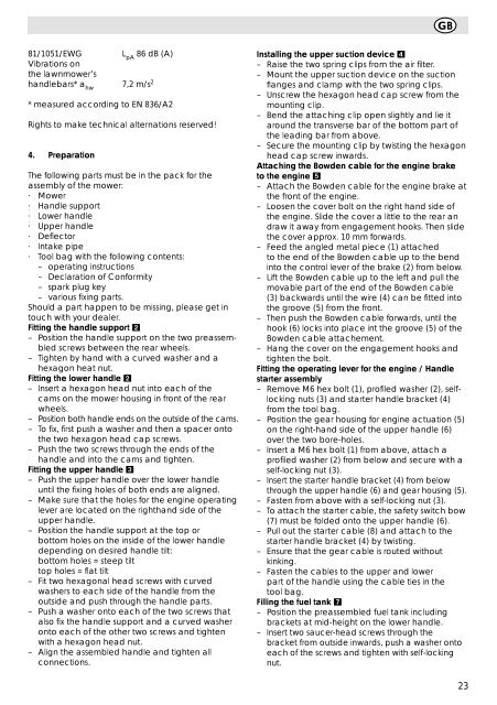
81/1051/EWG<br />
Vibrations on<br />
the lawnmower’s<br />
L 86 dB (A)<br />
pA<br />
handlebars* ahw 7,2 m/s2 * measured according to EN 836/A2<br />
Rights to make technical alternations reserved!<br />
4. Preparation<br />
The following parts must be in the pack for the<br />
assembly of the mower:<br />
· Mower<br />
· Handle support<br />
· Lower handle<br />
· Upper handle<br />
· Deflector<br />
· Intake pipe<br />
· Tool bag with the following contents:<br />
– operating instructions<br />
– Declaration of Conformity<br />
– spark plug key<br />
– various fixing parts.<br />
Should a part happen to be missing, please get in<br />
touch with your dealer.<br />
Fitting the handle support 2<br />
– Position the handle support on the two preassembled<br />
screws between the rear wheels.<br />
– Tighten by hand with a curved washer and a<br />
hexagon heat nut.<br />
Fitting the lower handle 2<br />
– Insert a hexagon head nut into each of the<br />
cams on the mower housing in front of the rear<br />
wheels.<br />
– Position both handle ends on the outside of the cams.<br />
– To fix, first push a washer and then a spacer onto<br />
the two hexagon head cap screws.<br />
– Push the two screws through the ends of the<br />
handle and into the cams and tighten.<br />
Fitting the upper handle 3<br />
– Push the upper handle over the lower handle<br />
until the fixing holes of both ends are aligned.<br />
– Make sure that the holes for the engine operating<br />
lever are located on the righthand side of the<br />
upper handle.<br />
– Position the handle support at the top or<br />
bottom holes on the inside of the lower handle<br />
depending on desired handle tilt:<br />
bottom holes = steep tilt<br />
top holes = flat tilt<br />
– Fit two hexagonal head screws with curved<br />
washers to each side of the handle from the<br />
outside and push through the handle parts.<br />
– Push a washer onto each of the two screws that<br />
also fix the handle support and a curved washer<br />
onto each of the other two screws and tighten<br />
with a hexagon head nut.<br />
– Align the assembled handle and tighten all<br />
connections.<br />
GB<br />
Installing the upper suction device 4<br />
– Raise the two spring clips from the air filter.<br />
– Mount the upper suction device on the suction<br />
flanges and clamp with the two spring clips.<br />
– Unscrew the hexagon head cap screw from the<br />
mounting clip.<br />
– Bend the attaching clip open slightly and lie it<br />
around the transverse bar of the bottom part of<br />
the leading bar from above.<br />
– Secure the mounting clip by twisting the hexagon<br />
head cap screw inwards.<br />
Attaching the Bowden cable for the engine brake<br />
to the engine 5<br />
– Attach the Bowden cable for the engine brake at<br />
the front of the engine.<br />
– Loosen the cover bolt on the right hand side of<br />
the engine. Slide the cover a little to the rear an<br />
draw it away from engagement hooks. Then slide<br />
the cover approx. 10 mm forwards.<br />
– Feed the angled metal piece (1) attached<br />
to the end of the Bowden cable up to the bend<br />
into the control lever of the brake (2) from below.<br />
– Lift the Bowden cable up to the left and pull the<br />
movable part of the end of the Bowden cable<br />
(3) backwards until the wire (4) can be fitted into<br />
the groove (5) from the front.<br />
– Then push the Bowden cable forwards, until the<br />
hook (6) locks into place int the groove (5) of the<br />
Bowden cable attachement.<br />
– Hang the cover on the engagement hooks and<br />
tighten the bolt.<br />
Fitting the operating lever for the engine / Handle<br />
starter assembly<br />
– Remove M6 hex bolt (1), profiled washer (2), selflocking<br />
nuts (3) and starter handle bracket (4)<br />
from the tool bag.<br />
– Position the gear housing for engine actuation (5)<br />
on the right-hand side of the upper handle (6)<br />
over the two bore-holes.<br />
– Insert a M6 hex bolt (1) from above, attach a<br />
profiled washer (2) from below and secure with a<br />
self-locking nut (3).<br />
– Insert the starter handle bracket (4) from below<br />
through the upper handle (6) and gear housing (5).<br />
– Fasten from above with a self-locking nut (3).<br />
– To attach the starter cable, the safety switch bow<br />
(7) must be folded onto the upper handle (6).<br />
– Pull out the starter cable (8) and attach to the<br />
starter handle bracket (4) by twisting.<br />
– Ensure that the gear cable is routed without<br />
kinking.<br />
– Fasten the cables to the upper and lower<br />
part of the handle using the cable ties in the<br />
tool bag.<br />
Filling the fuel tank 7<br />
– Position the preassembled fuel tank including<br />
brackets at mid-height on the lower handle.<br />
– Insert two saucer-head screws through the<br />
bracket from outside inwards, push a washer onto<br />
each of the screws and tighten with self-locking<br />
nut.<br />
23