Catalogo motori serie Sincrovert ® Motors catalogue ... - Oemer
Catalogo motori serie Sincrovert ® Motors catalogue ... - Oemer
Catalogo motori serie Sincrovert ® Motors catalogue ... - Oemer

Create successful ePaper yourself
Turn your PDF publications into a flip-book with our unique Google optimized e-Paper software.
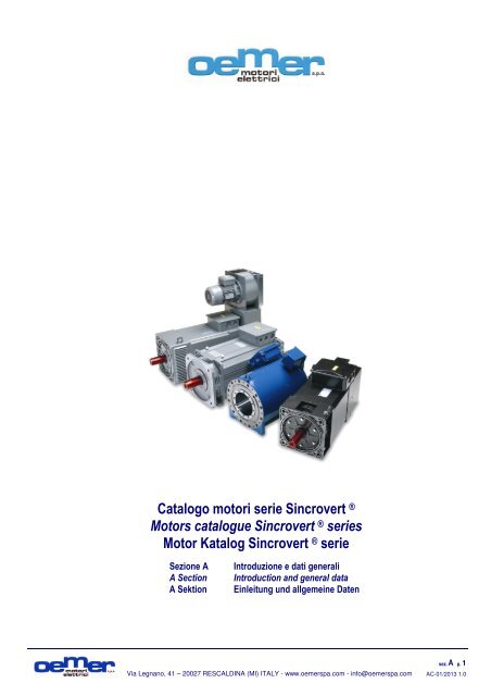
<strong>Catalogo</strong> <strong>motori</strong> <strong>serie</strong> <strong>Sincrovert</strong> <strong>®</strong><br />
<strong>Motors</strong> <strong>catalogue</strong> <strong>Sincrovert</strong> <strong>®</strong> <strong>serie</strong>s<br />
Motor Katalog <strong>Sincrovert</strong> <strong>®</strong> <strong>serie</strong><br />
Sezione A<br />
A Section<br />
A Sektion<br />
Introduzione e dati generali<br />
Introduction and general data<br />
Einleitung und allgemeine Daten<br />
Via Legnano, 41 – 20027 RESCALDINA (MI) ITALY - www.oemerspa.com - info@oemerspa.com<br />
sez. A p. 1<br />
AC-01/2013 1.0
Note:<br />
Via Legnano, 41 – 20027 RESCALDINA (MI) ITALY - www.oemerspa.com - info@oemerspa.com<br />
sez. A p. 2<br />
AC-01/2013 1.0
Programma di produzione Production program Produktionsprogramm<br />
0,55…1.115 kW<br />
Motore Asincrono 3-fase ad alte prestazioni per inverter<br />
AC 3-phase high performances inverter duty motor<br />
3-Phasen Asynchronmotor für Umrichterbetrieb<br />
550…2.870 Nm<br />
Motore Asincrono 3-fase a bassa inerzia per inverter<br />
AC 3-phase inverter duty very low inertia motor<br />
3-Phasen Asynchronmotor mit geringem Trägheitsmoment<br />
46…2300 Nm<br />
Servomotore Sincrono 3-fase a magneti permanenti<br />
AC 3-phase permanent magnets Synchronous servomotor<br />
3-Phasen Synchronmotor mit Permanentmagneten<br />
3,2…509 kW<br />
Motore asincrono 3-fase per inverter raffreddato a liquido<br />
AC 3-phase inverter duty liquid cooled asynchronous motor<br />
3-Phasen Asynchronmotor wassergekühlt für Umrichterbetrieb<br />
120…14.000 Nm<br />
Motore COPPIA sincrono raffreddato a liquido<br />
Liquid cooled synchronous TORQUE motor<br />
Torque-Motor wassergekühlt<br />
680…14.000 Nm<br />
Motore COPPIA sincrono raffreddato a liquido con reggispinta<br />
Liquid cooled synchronous TORQUE motor with thrust bearing<br />
Torque-Motor wassergekühlt mit Drucklager<br />
1…17 Nm<br />
Servomotore Asincrono per alimentazione da inverter<br />
AC 3-phase inverter duty asynchronous servomotor<br />
3-Phasen Asynchronmotor für Umrichterbetrieb<br />
0,12…9,5 kW<br />
Motore Asincrono 3-fase per alimentazione da inverter<br />
AC 3-phase inverter duty Asynchronous motor<br />
3-Phasen Asynchronmotor für Umrichterbetrieb<br />
0,12…15 kW<br />
Motore Asincrono 3-fase per alimentazione da inverter<br />
AC 3-phase inverter duty Asynchronous motor<br />
3-Phasen Asynchronmotor für Umrichterbetrieb<br />
5,5…630 kW<br />
Motore Asincrono 3-fase per alimentazione da inverter<br />
AC 3-phase inverter duty Asynchronous motor<br />
3-Phasen Asynchronmotor für Umrichterbetrieb<br />
Via Legnano, 41 – 20027 RESCALDINA (MI) ITALY - www.oemerspa.com - info@oemerspa.com<br />
HQLa -<br />
Par. 7.1<br />
P. B52…B73 HQL<br />
Par. 7.2<br />
P. B74…B81<br />
Par. 7.3<br />
P. B82…B89<br />
Par. 7.4<br />
P. B90…B99<br />
Par. 7.5<br />
P. B100…B109<br />
Par. 7.6<br />
P. B110…B117<br />
sez. A p. 3<br />
AC-01/2013 1.0<br />
HQLa-Li<br />
QLS<br />
LQ<br />
LTS<br />
LTS-TB<br />
Vp -<br />
Par. 7.7<br />
P. B118…127 QcaVs<br />
Par. 7.8<br />
P. B128…B135<br />
Par. 7.9<br />
P. B136…B143<br />
Par. 7.10<br />
P. B144…B151<br />
QCA<br />
MTS<br />
MTES
INDICE INDEX INHALTSVERZEICHNIS<br />
Pag Par<br />
A.1 Copertina sezione A Cover page section A Umschlagseite Abschnitt A<br />
A.2 Note Note Hinweise<br />
A.3 Programma di produzione Production program Produktionsprogramm<br />
A.4 Indice Index Inhaltsverzeichnis<br />
A.5 1.0 Introduzione Introduction Einleitung<br />
A.5 1.1 Generalità Generals Allgemeines<br />
A.5 1.2 Marchi e sigle di identificazione Trade marks and identification code Marken und produktcodes<br />
A.6 1.3 Prodotti Products Produkte<br />
A.6 1.4 Norme di riferimento Reference standards Geltende normen<br />
A.7 1.5 Certificazioni Certifications Zertifizierung<br />
A.7 1.6 Campi di applicazione Application fields Einsatzbereiche<br />
A.8 2.0 Forma costruttiva Mountings Bauform<br />
A.8 2.1 Golfari di sollevamento Lifting Hebeösen<br />
A.9 2.2 Grado di protezione Protection degree Schutzart<br />
A.10 2.2 Grado di protezione Protection degree Schutzart<br />
A.11 2.3 Raffreddamento, ventilazione Cooling, ventilation Kühlung, lüftung<br />
A.12 2.3 Raffreddamento, ventilazione Cooling, ventilation Kühlung, lüftung<br />
A.13 2.3 Raffreddamento, ventilazione Cooling, ventilation Kühlung, lüftung<br />
A.14 2.3 Raffreddamento, ventilazione Cooling, ventilation Kühlung, lüftung<br />
A.15 2.4 Rumorosità Noise Geräuschpegel<br />
A.16 2.5 Equilibratura Balancing Auswuchtung<br />
A.17 2.6 Albero Shaft Welle<br />
A.18 2.7 Flangia Flange Flansch<br />
A.19 2.8 Statore Stator Stator<br />
A.19 2.9 Rotore Rotor Läufer<br />
A.20 3.0 Cuscinetti Bearings Wälzlager<br />
A.21 3.0 Cuscinetti Bearings Wälzlager<br />
A.22 3.0 Cuscinetti Bearings Wälzlager<br />
A.23 3.1 Cuscinetti isolati Insulated bearings Elektrisch isolierte lager<br />
A.23 3.2 Tenute meccaniche Mechanical seals Mechanische wellenabdichtung<br />
A.24 3.3 Avvolgimento Winding Wicklung<br />
A.25 3.3 Avvolgimento Winding Wicklung<br />
A.26 3.4 Scatola morsetti Terminal box Klemmenkasten<br />
A.26 3.5 Morsettiera Terminal board Klemmleiste<br />
A.27 3.6 Termoprotettori Thermal protectors Überhitzungsschutz<br />
A.28 3.7 Alimentazione Supply Stromversorgung<br />
A.29 4.0 Freno Brake Bremsen<br />
A.30 4.0 Freno Brake Bremsen<br />
A.31 4.1 Trasduttore (encoder) Transducer (encoder) Messwertgeber (encoder)<br />
A.32 4.2 Scaldiglie anticondensa Space heaters Wicklungsheizung<br />
A.32 4.3 Verniciatura Paint Lackierung - farbe<br />
A.32 4.4 Trattamenti particolari Special treatments Sonderbehandlungen<br />
A.33 5.0 Curve caratteristiche Diagrams Kennlinien für den betrieb<br />
A.34 5.1 Velocità, frequenza, tensione Speed, frequency, voltage Drehzahl, frequenz, spannung<br />
A.35 5.2 Regolazione della tensione Voltage regulation Spannungsregelung<br />
A.36 5.3 Potenza e riscaldamento Power and heating Leistung und erwärmung<br />
A.37 5.4 Prestazioni Performances Leistungen<br />
A.38 5.5 Tipi di servizio Type of duty Betriebsarten<br />
A.38 5.6 Definizioni del tipo di servizio Duty definition Definitionen der betriebsarten<br />
A.39 5.7 Determinazione della potenza Power calculation Leistungsbestimmung bei aussetzbetrieb<br />
A.39 5.8 Rendimento e cosfi Efficency and power factor Leistung und leistungsfaktor cosϕ<br />
A.40 5.9 Tolleranza della tensione Voltage tolerance Spannungstoleranzen<br />
A.40 5.10 Tolleranze elettriche Electrical tolerance Elektrische toleranzen<br />
A.40 5.11 Tolleranze meccaniche Mechanical tolerance Mechanische toleranzen<br />
A.41 6.0 Targa identificativa Identification name plate Typenschild<br />
A.41 6.1 Legenda della targa Name plate description Typenschildkennzeichnung<br />
A.42 6.2 Codifica motore Motor code Motorkennzeichnung<br />
A.43 6.2 Codifica motore Motor code Motorkennzeichnung<br />
A.44 6.3 Modulo richiesta motore Motor request form Motorbestellformular<br />
A.45 6.4 Condizioni di vendita Sales conditions Verkaufsbedingungen<br />
A.46 6.5 Avvertenze Warnings Hinweise<br />
A.47 Note Note Hinweise<br />
A.48 Note Note Hinweise<br />
B.49 Copertina sezione B Cover page section B Umschlagseite Abschnitt B<br />
B.50 Avvertenze Warnings Warnhinweise<br />
B.51 7.0 Programma di produzione Production program Produktionsprogramm<br />
B.52 7.1 Schede tecniche <strong>motori</strong> <strong>Motors</strong> data sheet Technische Datenblätter Moto<br />
B.150 7.10 Schede tecniche <strong>motori</strong> <strong>Motors</strong> data sheet Technische Datenblätter Motor<br />
B.151 Note Note Hinweise<br />
B.152 Note Note Hinweise<br />
Via Legnano, 41 – 20027 RESCALDINA (MI) ITALY - www.oemerspa.com - info@oemerspa.com<br />
sez. A p. 4<br />
AC-01/2013 1.0
1.0 INTRODUZIONE<br />
Abbiamo realizzato questo nuovo catalogo per<br />
permetterVi di usufruire delle informazioni tecniche<br />
relative ai nostri prodotti senza ricorrere<br />
necessariamente all’utilizzo del computer o di internet<br />
per consultare i documenti o scaricare i files.<br />
La nostra politica aziendale ci spinge sempre di<br />
più a divulgare le informazioni tecniche in modo<br />
capillare ma al tempo stesso è anche fortemente<br />
rivolta alla salvaguardia dell’ambiente ed alla<br />
riduzione degli sprechi. Anche l’ottimizzazione e<br />
la riduzione dell’utilizzo della carta e<br />
dell’inchiostro rientrano nei nostri obiettivi primari.<br />
Per questo motivo è stata sospesa la stampa dei<br />
cataloghi suddivisi per linea di prodotto che, pur<br />
essendo ottimi supporti per la divulgazione delle<br />
informazioni, richiedevano l’utilizzo di molte più<br />
pagine a causa del ripetersi degli argomenti per<br />
ogni singolo catalogo.<br />
Abbiamo pertanto deciso di concentrare in<br />
questo catalogo le informazioni tecniche valide<br />
per tutte le linee di prodotto riducendo il numero<br />
della pagine stampate annualmente pur<br />
mantenendo inalterata la completezza delle<br />
informazioni ed il loro aggiornamento.<br />
1.1 GENERALITÀ<br />
Il presente catalogo è composto da una parte<br />
introduttiva che fornisce informazioni tecniche<br />
generali valide per tutti i <strong>motori</strong> (sez. A) e da<br />
sezioni specifiche valide per ogni singolo<br />
prodotto (sez. B)<br />
E’ essenziale disporre di tutta la documentazione<br />
per ottenere informazioni complete ed utili per il<br />
dimensionamento e la scelta del motore.<br />
1.2 MARCHI E SIGLE DI IDENTIFICAZIONE<br />
<strong>Sincrovert</strong><strong>®</strong><br />
E’ un marchio registrato dalla OEMER MOTORI<br />
ELETTRICI SPA.<br />
QL, QLa, HQL, HQLa, QLa-Li, HQLa-Li,<br />
QLS, QCA, MT, MTE, MTS, MTES, LQ,<br />
LTS, QcaVs, QcaVm, QcaVp, QcaVma,<br />
QcaSn, QcaC<br />
Sono sigle utilizzate dalla OEMER MOTORI<br />
ELETTRICI SPA per identificare i propri prodotti.<br />
1.0 INTRODUCTION<br />
We have published this new <strong>catalogue</strong> to provide<br />
you with technical information on our products<br />
even if you don't have access to a computer or<br />
Internet to consult documents online or download<br />
the files.<br />
Our company policy encourages us to<br />
disclose technical information in a capillary<br />
way, with a concrete interest in the protection<br />
of the environment and reducing waste. Our<br />
primary objectives include reducing the use of<br />
paper and ink.<br />
This is why we have stopped printing<br />
<strong>catalogue</strong>s for each product line, because<br />
while they are an excellent instrument for<br />
disclosing information, this method does<br />
involve printing many more pages, as the<br />
subjects often tend to be repeated in each<br />
single <strong>catalogue</strong>.<br />
Therefore, we have decided to concentrate in<br />
this new <strong>catalogue</strong> the technical information<br />
valid for all the product lines reducing the<br />
number of printed pages, while continuing to<br />
provide complete, up-to-date information to<br />
our Customers.<br />
1.1 GENERAL INFORMATION<br />
The present technical catalog is composed by an<br />
introductory part giving general information about all<br />
sizes and <strong>serie</strong>s of motors (sec. A) and by specific<br />
section valid for each single <strong>serie</strong> of motors (sec. B).<br />
You will need all of the relevant documentation to<br />
have full access to the available technical information<br />
concerning the dimensioning and choice of the<br />
correct motor.<br />
1.2 TRADE AND IDENTIFICATION MARKS<br />
<strong>Sincrovert</strong><strong>®</strong><br />
Is a registered trademark of the OEMER<br />
MOTORI ELETTRICI SPA.<br />
QL, QLa, HQL, HQLa, QLa-Li, HQLa-Li,<br />
QLS, QCA, MT, MTE, MTS, MTES, LQ,<br />
LTS, QcaVs, QcaVm, QcaVp, QcaVma,<br />
QcaSn, QcaC<br />
Are marks used by OEMER MOTORI ELETTRICI<br />
SPA to identify its products.<br />
1.0 EINLEITUNG<br />
Unser neuer Katalog wurde erstellt, um Ihnen<br />
direkten Zugriff auf technische Informationen zu<br />
unseren Produkten zu ermöglichen, sodass Sie<br />
nicht zwingend Computer und Internet verwenden<br />
müssen, um Unterlagen zu konsultieren oder<br />
Dateien zu downloaden.<br />
Unsere Firmenpolitik veranlasst uns, technische<br />
Informationen in immer stärkerem Maße detailliert<br />
zur Verfügung zu stellen und ist gleichzeitig stark<br />
auf Umweltschutz ausgerichtet. Zu unseren<br />
Hauptzielen gehören auch die Optimierung und<br />
Verringerung des Einsatzes von Papier und<br />
Druckfarbe.<br />
Aus diesem Grund wurde der Druck einzelner<br />
Kataloge der Produktbaureihen, obwohl eine<br />
optimale Hilfe, eingestellt. Wegen der sich<br />
wiederholenden Themen wären jedoch in jedem<br />
Katalog deutlich mehr Seiten erforderlich.<br />
Wir haben deshalb entschieden, die allgemeinen<br />
technischen Informationen für alle Produktbaureihen<br />
in nur einem Katalog zu bündeln und auf<br />
Grundlage der tatsächlichen Kundenbedürfnisse<br />
lediglich die entsprechenden erforderlichen<br />
Datenblätter gesondert zur Verfügung zu stellen.<br />
1.1 ALLGEMEINES<br />
Dieser Katalog besteht aus einer Einführung mit<br />
allgemeinen technischen Informationen zu allen<br />
Motoren und aus spezifischen Abschnitten für<br />
jedes einzelne Produkt.<br />
Um alle für die Auswahl von Motor und<br />
Motorgröße zweckmäßigen Informationen zu<br />
erhalten, sollten Sie über die gesamte<br />
Dokumentation verfügen.<br />
1.2 MARKEN UND PRODUKTCODES<br />
<strong>Sincrovert</strong> <strong>®</strong><br />
Ist eine eingetragene Marke von OEMER<br />
MOTORI ELETTRICI SpA.<br />
QL, QLa, HQL, HQLa, QLa-Li, HQLa-Li,<br />
QLS, QCA, MT, MTE, MTS, MTES, LQ,<br />
LTS, QcaVs, QcaVm, QcaVp, QcaVma,<br />
QcaSn, QcaC<br />
Sind vom Unternehmen OEMER SpA zur<br />
Produktidentifizierung verwendete Kürzel.<br />
Via Legnano, 41 – 20027 RESCALDINA (MI) ITALY - www.oemerspa.com - info@oemerspa.com<br />
sez. A p. 5<br />
AC-01/2013 1.0
1.3 PRODOTTI<br />
Questo catalogo contiene le informazioni di<br />
carattere generale e tecnico relative ai <strong>motori</strong> 3fase<br />
costruiti per utilizzo a velocità variabile<br />
tramite alimentazione da convertitore di<br />
frequenza (inverter).<br />
Sono contemplati <strong>motori</strong> 3-fase asincroni unificati<br />
e speciali, <strong>motori</strong> sincroni a magneti permanenti<br />
e <strong>motori</strong> coppia.<br />
In particolare si fa riferimento alle seguenti <strong>serie</strong><br />
di <strong>motori</strong>:<br />
QL, QLa, HQL, HQLa:<br />
Motori asincroni 3-fase raffreddati ad aria, ad alte<br />
prestazioni per alimentazione da inverter.<br />
HQLa-Li<br />
Servo<strong>motori</strong> asincroni 3-fase raffreddati ad aria, a<br />
bassissima inerzia rotorica<br />
LQ<br />
Motori asincroni 3-fase raffreddati a liquido, ad<br />
alte prestazioni per alimentazione da inverter.<br />
QLS<br />
Servo<strong>motori</strong> sincroni a magnenti permanenti<br />
raffreddati ad aria.<br />
LTS, LTS-TB<br />
Motori coppia sincroni a magneti permanenti<br />
raffreddati a liquido.<br />
QcaVs, QcaVp<br />
Servo<strong>motori</strong> asincroni 3-fase raffreddati ad aria<br />
QCA, MTS, MTES<br />
Motori asincroni 3-fase unificati per alimentazione<br />
da inverter<br />
1.4 NORME DI RIFERIMENTO<br />
Elenco delle norme citate nel presente catalogo a<br />
cui fare riferimento.<br />
Note: Alcune <strong>serie</strong> specifiche di <strong>motori</strong> NON<br />
rispettano totalmente le norme di unificazione, in<br />
particolar modo per quanto riguarda le dimensioni<br />
di ingombro rispetto alla potenza nominale.<br />
1.3 PRODUCTS<br />
This <strong>catalogue</strong> contains general and technical<br />
information on 3-phase motors built to operate at<br />
variable speed and powered by a frequency<br />
converter (inverter).<br />
The products mentioned are unified 3-phase<br />
standard and special asynchronous motors,<br />
permanent magnet synchronous motors and<br />
torque motors.<br />
In particular the <strong>catalogue</strong> covers the following<br />
<strong>serie</strong>s of motors:<br />
QL, QLa, HQL, HQLa:<br />
High-performance, air-cooled 3-phase<br />
asynchronous motors, powered by inverter.<br />
HQLa-Li<br />
Air-cooled 3-phase asynchronous servomotors,<br />
with low rotary inertia<br />
LQ<br />
High-performance, liquid-cooled 3-phase<br />
asynchronous motors, powered by inverter.<br />
QLS<br />
Air-cooled, permanent magnet synchronous<br />
servomotors.<br />
LTS, LTS-TB<br />
Liquid-cooled, permanent magnet synchronous<br />
torque motors.<br />
QcaVs, QcaVp<br />
Air-cooled 3-phase asynchronous servomotors<br />
QCA, MTS, MTES<br />
Unified standard 3-phase asynchronous motors<br />
powered by inverter<br />
1.4 STANDARDS OF REFERENCE<br />
List of standards mentioned in the present<br />
<strong>catalogue</strong> to be referred to.<br />
Note: Some specific <strong>serie</strong>s of motors do NOT<br />
fully respect the unified standards. In particular<br />
this is valid for the overall dimensions of the<br />
motors respect to the nominal power.<br />
1.3 PRODUKTE<br />
In diesem Katalog sind allgemeine Informationen<br />
über Drehstrommotoren enthalten, die für den<br />
Einsatz mit variablem, durch einen<br />
Frequenzumrichter (Inverter) gesteuertem<br />
Drehmoment entworfen wurden.<br />
Berücksichtigt sind genormte und nicht genormte<br />
Asynchronmotoren, Permanentmagnet-<br />
Synchronmotoren und Torquemotoren.<br />
Auf folgende Motorbaureihen wird im Einzelnen<br />
Bezug genommen:<br />
QL, QLa, HQL, HQLa:<br />
Luftgekühlte Hochleistungs-Drehstrom-<br />
Asynchronmotoren für Invertersteuerung.<br />
QLa-Li, HQLa-Li<br />
Luftgekühlte Drehstrom-Asynchron-Servomotoren<br />
mit äußerst geringer Rotationsträgheit.<br />
LQ<br />
Flüssigkeitsgekühlte Hochleistungs-Drehstrom-<br />
Asynchronmotoren für Invertersteuerung.<br />
QLS<br />
Luftgekühlte Synchron-Servomotoren mit<br />
Permanentmagneten.<br />
LTS, LTS-TB<br />
Flüssigkeitsgekühlte Synchron-Torquemotoren<br />
mit Permanentmagneten.<br />
QcaVs, QcaVp<br />
Drehstrom-Asynchron-Servomotoren.<br />
QCA, MTS, MTES<br />
Genormte Drehstrom-Asynchronmotoren für<br />
Invertersteuerung.<br />
1.4 GELTENDE NORMEN<br />
Cod. Titolo Title Bezeichnung<br />
Auflistung der im Katalog angeführten<br />
Referenznormen.<br />
Hinweise: Einige spezielle Motorbaureihen<br />
entsprechen insbesondere hinsichtlich<br />
Außenmaßen und Kühlverfahren NICHT<br />
vollumfänglich den harmonisierten Normen.<br />
IEC 60034-1 Caratteristiche nominali e di funzionamento Rating and performances Nenn- und Betriebsmerkmale<br />
IEC 60034-2 Metodi di determinazione delle perdite Methods for determining losses and efficiency Methode über Verlustfaktormessung<br />
IEC 60034-5 Classificazione dei gradi di protezione Classification of the degrees of protection Klassifizierung nach Schutzarten der Gehäuse<br />
IEC 60034-6 Metodi di raffreddamento Methods of cooling Kühlsysteme<br />
IEC 60034-7 Classificazione delle forme costruttive Type of construction and mounting arrangements Klassifizierung nach Bauformen<br />
IEC 60034-8 Marcatura dei terminali e senso di rotazione. Terminal markings and direction of rotation Kennzeichnungen Endklemmen u. Drehrichtung<br />
IEC 60034-9 Limiti di rumore Noise limits Störbegrenzungen<br />
IEC 60034-14 Vibrazioni meccaniche di macchine rotanti Mechanical vibrations of rotating machines Mech. Vibrationen bei drehenden Maschinen<br />
IEC 60034-15 Livelli di tensione di tenuta ad impulso Impulse voltage withstand levels Spannungsstufen der Impulsfestigkeit<br />
IEC 60072-1 Dimensioni e potenze delle macchine elettriche Dimensions and output <strong>serie</strong>s for rotating mach. Maße u. Leistungen elektrischer Maschinen<br />
IEC 1293 Marcatura delle apparecchiature elettriche Markings of electrical devices Kennzeichnung elektrischer Geräte<br />
UNI ISO 2768/1-2 Tolleranze generali General tolerances Allgemeine Toleranzen<br />
UNI 9321 Estremità d’albero Shaft end Wellenenden<br />
UNI ISO 8015 Disegni tecnici e tolleranze Technical drawings and tolerances Technische Daten und Tolleranzen<br />
73/23 – 93/68 Direttiva Bassa Tensione Low voltage directive Richtlinie: Niederspannung<br />
(EMC): 89/336 - 93/68 Direttiva Compatibilità Elettromagnetica Electromagnetic compatibility directive Richtlinie: Elektromagn. Verträglichkeit<br />
89/392 - 93/68 Direttiva Macchine Machine directive Maschinenrichtlinie<br />
UL1004 * Motori elettrici Electric motors Elektrische Motoren<br />
UL1446 * Sistemi di materiali isolanti Systems of insulating materials Isolationsmaterialien<br />
* Solo per alcune grandezze/<strong>serie</strong> di <strong>motori</strong>.<br />
Via Legnano, 41 – 20027 RESCALDINA (MI) ITALY - www.oemerspa.com - info@oemerspa.com<br />
sez. A p. 6<br />
AC-01/2013 1.0
1.5 CERTIFICAZIONI 1.5 CERTIFICATIONS 1.5 ZERTIFIZIERUNG<br />
Certificazione ISO 9000 - ISO 9000 certification -Zertifizierung nach ISO 9000<br />
1.6 CAMPI DI APPLICAZIONE<br />
I prodotti elencati nel presente catalogo sono<br />
progettati, costruiti e consegnati esclusivamente<br />
per installazione in ambiente industriale neutro.<br />
Se non espressamente indicato si ritengono<br />
valide le condizioni di utilizzo standard previste<br />
dalle norme sopra citate e quindi:<br />
Temperatura ambiente: -20…+ 40°C<br />
Altitudine: 0…+ 1000m slm<br />
Ambiente: chimicamente non aggressivo<br />
Qualsiasi utilizzo del motore in condizioni diverse<br />
da quanto stabilito deve essere valutato<br />
preventivamente e concordato con il produttore<br />
del motore.<br />
Per installazioni particolari potrebbero essere<br />
richiesti accessori specifici che devono garantire<br />
l’utilizzo ed il funzionamento del motore in<br />
condizioni di sicurezza. E’ indispensabile<br />
comunicare al costruttore tutti i dettagli per<br />
ottenere un prodotto completamente conforme a<br />
quanto previsto dalle specifiche di utilizzo.<br />
1.6 FIELDS OF APPLICATION<br />
The products listed in this <strong>catalogue</strong> are<br />
exclusively designed and made for installation in<br />
neutral industrial environments.<br />
Unless specifically indicated, the usual conditions<br />
of use envisaged by the above standard are<br />
considered valid, in other words:<br />
Ambient temperature: -20…+ 40°C<br />
Altitude: 0…+ 1000m asl<br />
Environment: not chemically aggressive<br />
Any use of the motor in different conditions to<br />
those established must be previously evaluated<br />
and agreed on with the manufacturer of the<br />
motor.<br />
Special installations conditions may require<br />
specific accessories that must guarantee the<br />
motor is used and functions in safe operating<br />
conditions. The manufacturer must be provided<br />
with all the relevant technical details in order to<br />
obtain a product which is suitable for the<br />
envisaged use.<br />
Dichiarazione di conformità - Declaration of conformity – Konformitätserklärung<br />
1.6 EINSATZBEREICHE<br />
Die in diesem Katalog angeführten Produkte<br />
wurden ausschließlich für den Einsatz in chemisch<br />
neutralen Bereichen von Industriebetrieben<br />
entworfen, konstruiert und gebaut. Sofern nicht<br />
ausdrücklich andere Bedingungen angegeben<br />
sind, gelten die Standard-Einsatzbedingungen der<br />
vorstehend genannten Normen:<br />
Umgebungstemperatur: -20 bis + 40 °C<br />
Höhe: 0 bis + 1000 m ü.M.<br />
Umgebung: chemisch nicht aggressiv<br />
Jeglicher Einsatz der Motoren unter anderen als<br />
den angegebenen Bedingungen ist vorab zu prüfen<br />
und mit dem Motorhersteller abzustimmen.<br />
Für individuelle Anlagen könnten spezielle<br />
Zubehörteile erforderlich sein, die den sicheren<br />
Einsatz und Betrieb des <strong>Motors</strong> zu gewährleisten<br />
haben. Um ein vollständig den Einsatzspezifikationen<br />
entsprechendes Produkt zu erhalten, sind<br />
dem Hersteller zwingend sämtlich Details<br />
mitzuteilen.<br />
Via Legnano, 41 – 20027 RESCALDINA (MI) ITALY - www.oemerspa.com - info@oemerspa.com<br />
sez. A p. 7<br />
AC-01/2013 1.0
2.0 FORMA COSTRUTTIVA<br />
I <strong>motori</strong> sono realizzati nelle forme costruttive<br />
indicate nella tabella successiva secondo le<br />
norme IEC 60034-7.<br />
Flange e alberi speciali o attacchi non di <strong>serie</strong><br />
sono disponibili a richiesta.<br />
Il montaggio con la sola flangia IM 3001 (B5) non<br />
è consentito per alcune grandezze ed è pertanto<br />
necessario prevedere la struttura della macchina<br />
per la forma costruttiva IM 2001 (B35) od in<br />
alternativa un supporto posteriore per il motore.<br />
Per il montaggio in posizione verticale consultare<br />
sempre il costruttore del motore per verificare<br />
eventuali opzioni o modifiche da apportare al<br />
motore e/o agli eventuali accessori. In genere per<br />
questo tipo di montaggio è necessario prevedere<br />
un riparo superiore (es. tettuccio parapioggia)<br />
che garantisca la ventilazione ed il corretto<br />
raffreddamento del motore ma al tempo stesso<br />
impedisca a piccoli oggetti e/o acqua di cadere<br />
direttamente sul motore<br />
I <strong>motori</strong> non unificati hanno flange ed alberi<br />
costruiti con dimensioni secondo le norme IEC<br />
60034-7 ma la combinazione di flange, alberi ed<br />
altezza d’asse potrebbe non corrispondere alla<br />
grandezza (altezza d’asse) del motore. E’<br />
importante consultare sempre il disegno tecnico<br />
del motore scelto per verificare l’effettiva<br />
compatibilità meccanica con il riduttore o la<br />
macchina a cui sarà accoppiato.<br />
Alcuni <strong>motori</strong> sono costruiti con flange ed alberi<br />
speciali (es. <strong>motori</strong> LTS, LTS-TB)<br />
MOTORI CON PIEDI<br />
FOOT MOUNTED MOTORS<br />
MOTOREN MIT FUßMONTAGE<br />
IM B3<br />
IM 1001<br />
IM B8<br />
IM 1071<br />
IM B6<br />
IM 1051<br />
IM B7<br />
IM 1061<br />
2.1 GOLFARI DI SOLLEVAMENTO<br />
IM V6<br />
IM 1031<br />
IM V5<br />
IM 1011<br />
I <strong>motori</strong> con peso superiore a 20kg circa sono tutti<br />
provvisti di golfari di sollevamento che ne<br />
agevolano la movimentazione e l’installazione sulla<br />
macchina. Il tipo di golfare, la posizione di fissaggio<br />
e la dimensione varia da motore a motore in<br />
funzione della struttura meccanica e del peso. In<br />
genere sono presenti due golfari superiori posti in<br />
diagonale rispetto all’albero del motore ma<br />
esistono anche versioni con golfari allineati tra loro<br />
oppure con singolo golfare centrale.<br />
2.0 CONSTRUCTION FORM<br />
The motors are manufactured in the<br />
configurations indicated in the following table, in<br />
accordance with standard IEC 60034-7.<br />
Special flanges or non standard fixing elements<br />
are available on request.<br />
The IM 3001 (B5) flange mounting only is not<br />
permitted for some sizes of motors, therefore it is<br />
necessary to foresee the structure of the machine<br />
for the IM 2001 (B35) mounting or as alternative<br />
a rear support for the motor.<br />
For vertical installations, it is raccomanded to<br />
consult the manufacturer of the motor to verify if<br />
some modifications on the motors or on the<br />
options are necessary. In general, for this type of<br />
installation a protective top cover (e.g. rain guard)<br />
is necessary to guarantees sufficient ventilation<br />
and cooling of the motor and prevents foreign<br />
bodies and/or water getting into the motor<br />
structure or into the options installed on the rear<br />
side of it.<br />
Non-standard motors have flanges and shafts<br />
made with dimensions in accordance with<br />
standard IEC 60034-7 but the combination of<br />
flange, shaft and axial height may not correspond<br />
to the dimensions (shaft height) of the motor.<br />
Always consult the technical drawing of the motor<br />
to make sure it is mechanically compatible with<br />
the gearbox or mechanical transmission that will<br />
be coupled to the motor.<br />
Some motors are made with special flanges and<br />
shafts (e.g. motors LTS, LTS-TB)<br />
MOTORI CON FLANGIA A FORI PASSANTI<br />
FLANGE MOUNTED WITH THROUGH HOLES<br />
MOTOREN MIT FLANSCH UND BOHRUNGEN<br />
IM B5<br />
IM 3001<br />
IM B35<br />
IM 2001<br />
2.1 LIFTING EYEBOLTS<br />
IM V3<br />
IM 3031<br />
IM V36<br />
IM 2031<br />
IM V1<br />
IM 3011<br />
IM V15<br />
IM 2011<br />
<strong>Motors</strong> weighing more than approximately 20kg<br />
come with lifting eyebolts to make confortable<br />
and safe manoeuvring and installation on the<br />
machine. The type of eyebolt, the position and<br />
size varies from motor to motor on the basis of<br />
the mechanical design and weight of the same. In<br />
general there are two top eyebolts in a diagonal<br />
position with respect to the shaft, but some<br />
versions also have eyebolts in line or one single<br />
central eyebolt.<br />
2.0 BAUFORM<br />
Die Motoren sind in den in der nachstehenden<br />
Tabelle angeführten Bauformen gemäß Norm IEC<br />
60034-7 ausgeführt.<br />
Sonderflansche oder nicht <strong>serie</strong>nmäßige Wellen<br />
sind auf Anfrage verfügbar.<br />
Für einige Baugrößen ist eine Montage nur mit der<br />
Flansch IM 3001 (B5) nicht zulässig. In diesem Fall<br />
ist die Konstruktion für Bauform IM 2001 (B35) oder<br />
alternativ ein hinteres Motorlager vorzusehen.<br />
Bei vertikaler Montage ist stets der Motorhersteller<br />
zu konsultieren: Es müssen mögliche Alternativen<br />
oder am Motor und/oder an etwaigen Zubehörteilen<br />
vorzunehmende Änderungen überprüft werden. In<br />
der Regel ist bei dieser Montageart eine über dem<br />
Motor anzubringende Schutzvorrichtung<br />
vorzusehen, die Belüftung und Kühlung des <strong>Motors</strong><br />
gewährleistet und gleichzeitig verhindert, dass<br />
kleine Gegenstände und/oder Wasser direkt auf<br />
den Motor gelangen (z.B. Regenhaube).<br />
Nicht genormte Motoren verfügen über Flansche<br />
und Welle mit Abmessungen gemäß Norm IEC<br />
60034-7. Die Kombination von Flanschen, Wellen<br />
und Achshöhe entspricht allerdings möglicherweise<br />
nicht der Baugröße (Achshöhe). Zur Überprüfung<br />
der tatsächlichen mechanischen Kompatibilität mit<br />
dem Untersetzungsgetriebe oder der Maschine, an<br />
die der Motor angeschlossen wird, ist unbedingt<br />
stets die technische Zeichnung des gewählten<br />
<strong>Motors</strong> zu konsultieren. Einige Motoren verfügen<br />
über Sonderflansche und -wellen (z.B. Motoren<br />
LTS, LTS-TB).<br />
MOTORI CON FLANGIA A FORI FILETTATII<br />
FLANGE MOUNTED WITH THREADED HOLES<br />
MIT FLANSCH U. GEWINDEBOHRUNGEN<br />
IM B14<br />
IM 3611<br />
IM B34<br />
IM 2101<br />
2.1 HEBEÖSEN<br />
IM V19<br />
IM 3631<br />
IM V69<br />
IM 2131<br />
Via Legnano, 41 – 20027 RESCALDINA (MI) ITALY - www.oemerspa.com - info@oemerspa.com<br />
IM V18<br />
IM 3611<br />
IM V58<br />
IM 2111<br />
Motoren mit einem Gewicht über 20 kg sind mit<br />
Hebeösen versehen, die Handling und Montage<br />
des <strong>Motors</strong> an der Maschine erleichtern. Art,<br />
Befestigungsposition und Maße der Öse sind in<br />
Abhängigkeit von mechanischer Konstruktion und<br />
Gewicht von Motor zu Motor unterschiedlich. In der<br />
Regel befinden sich an der Oberseite zwei<br />
diagonal zur Antriebswelle liegende Ösen. Es gibt<br />
aber auch Ausführungen mit in Linie liegenden<br />
Ösen oder einer einzelnen Öse in der Mitte.<br />
sez. A p. 8<br />
AC-01/2013 1.0
2.2 GRADO DI PROTEZIONE<br />
Per grado di protezione si intende la capacità<br />
della struttura meccanica del motore ad impedire<br />
la penetrazione all’interno di agenti esterni<br />
(piccoli oggetti, polvere, acqua) che possono<br />
causare effetti dannosi.<br />
Per la scelta corretta del motore è indispensabile<br />
valutare quali condizioni ambientali saranno<br />
presenti durante il suo funzionamento e<br />
selezionare il grado di protezione che ne<br />
garantisca l’affidabilità .<br />
I <strong>motori</strong> elettrici trattati in questo catalogo si<br />
possono suddividere in due distinte tipologie<br />
costruttive:<br />
Motori chiusi nei quali l’aria dell’ambiente<br />
circostante lambisce unicamente la superficie<br />
esterna.<br />
Motori protetti (aperti) nei quali l’aria penetra<br />
anche all’interno del motore per ottimizzare il<br />
raffreddamento.<br />
I <strong>motori</strong> chiusi sono generalmente costruiti con<br />
grado di protezione IP 54 che assicura un livello<br />
di protezione adeguato per gli ambienti industriali<br />
più comuni. Se le condizioni ambientali o di<br />
installazione lo richiedono è possibile<br />
incrementare tale grado di protezione agendo<br />
sulle chiusure degli accoppiamenti e sulle tenute<br />
dell’ albero.<br />
I <strong>motori</strong> protetti (aperti) sono costruiti con grado<br />
di protezione IP 23 che assicura un discreto<br />
livello di protezione contro la contaminazione del<br />
motore permettendo di sviluppare prestazioni<br />
sensibilmente più elevate rispetto ad un motore<br />
chiuso della stessa grandezza.<br />
E’ importante considerare Il grado di protezione<br />
di un motore elettrico unitamente al sistema di<br />
ventilazone utilizzato.<br />
Breve descrizione dei gradi di protezione:<br />
IP 23S<br />
Macchina protetta contro la penetrazione di corpi<br />
solidi di diametro superiore a 12 mm e contro la<br />
pioggia. (Protezione contro il contatto di dita od<br />
oggetti simili di lunghezza non superiore ad 80<br />
mm con parti in tensione od in movimento<br />
all’interno dell’involucro o loro avvicinamento tra<br />
le parti. L’acqua che cade a pioggia secondo una<br />
direzione inclinata di un angolo inferiore od<br />
uguale a 60° non deve provocare effetti dannosi).<br />
Note: Nei <strong>motori</strong> costruiti con grado di protezione<br />
IP 23 il mezzo refrigerante (aria) passa anche<br />
all’interno degli avvolgimenti e nel rotore. Per<br />
questo motivo questo tipo di protezione non è<br />
indicato per installazioni in ambienti polverosi,<br />
molto umidi o con forte contaminazione dell’aria.<br />
IP 54<br />
Macchina protetta contro la polvere e spruzzi<br />
d’acqua. (Protezione contro il contatto od<br />
avvicinamento con parti in tensione od in<br />
movimento all’interno dell’involucro). La<br />
penetrazione di polvere non è completamente<br />
impedita ma questa non deve poter entrare in<br />
quantità sufficiente a compromettere il buon<br />
funzionamento della macchina. L’acqua<br />
spruzzata sulla macchina da qualsiasi direzione<br />
non deve provocare effetti dannosi.<br />
2.2 DEGREE OF PROTECTION<br />
For the degree of protection is intended the<br />
capacity of the mechanical structure of the motor<br />
to prevent external agents getting inside (small<br />
bodies, dust, water) which could damage the<br />
motor.<br />
To choose the right motor carefully assess the<br />
ambient operating conditions presents where the<br />
motor will be installed and choose a suitable<br />
degree of protection that can guarantee the<br />
reliable service of the motor.<br />
The electric motors listed in this technical<br />
<strong>catalogue</strong> can be divided into two specific<br />
constructional types:<br />
Closed motors where the surrounding air is only<br />
in contact with the outer surface of the motor<br />
structure.<br />
Protected (open) motors where the air is in<br />
contact also with the internals of the motor to<br />
optimize the cooling.<br />
Closed motors normally are made with protection<br />
degree IP 54 which normally guarantees a<br />
suitable protection for standard industrial<br />
environments. If the environmental or installation<br />
conditions require, the degree of protection can<br />
be increased with interventions on the couplings<br />
of mechanical components and with appropriate<br />
shaft seals.<br />
The protected (open) motors are made with<br />
protection degree IP 23 which normally<br />
guarantees a discrete mechanical protection<br />
against contamination of the motor and<br />
increased performances if compared to the<br />
closed motors of the same frame size.<br />
It is important to consider the degree of<br />
protection of the electric motor with the cooling<br />
system used.<br />
Brief description of degrees of protection:<br />
IP 23S<br />
Protection against penetration of solid objects<br />
greater than 12mm diameter and against the rain.<br />
(Protection against contact of under voltage<br />
connections and windings or rotating and moving<br />
components located inside the enclosure by<br />
fingers or similar objects not exceeding 80 mm in<br />
length. The water falling as rain at an angle of up<br />
to 60° from the vertical shall have no harmful<br />
effect on the motor).<br />
Note: In motors built with an IP 23 degree of<br />
protection, the cooling medium (air) passes also<br />
inside the windings and in the rotor. Therefore,<br />
this type of protection is not suitable for<br />
installation in dusty, very damp or highly<br />
contaminated environments.<br />
IP 54<br />
Protection against dust and splashing water from<br />
any direction. (Protection against contact with or<br />
approach to under voltage or moving parts<br />
located inside the motor enclosure. Penetration<br />
of dust into machine is not totally prevented but<br />
dust does not enter in a sufficient quantity to<br />
interfere with reliable and satisfactory operation<br />
of the machine). Water splashing against the<br />
machine from any direction shall have no harmful<br />
effect).<br />
2.2 SCHUTZART<br />
Unter Schutzart (Schutzgrad) versteht man die<br />
Fähigkeit der mechanischen Konstruktion des<br />
<strong>Motors</strong>, das Eindringen von möglicherweise<br />
Schäden verursachenden Fremdkörpern (kleinen<br />
Gegenständen, Staub, Wasser) zu verhindern.<br />
Für die richtige Motorauswahl ist unbedingt zu<br />
berücksichtigen, in welchen Umgebungsbedingen<br />
der Motor betrieben werden wird, und<br />
dementsprechend eine Schutzart auszuwählen, die<br />
seine Betriebssicherheit gewährleistet.<br />
Die in diesem Katalog enthaltenen Motoren<br />
können in zwei verschiedene Bauarten unterteilt<br />
werden:<br />
Geschlossene Motoren, bei denen die<br />
umgebende Raumluft lediglich an den<br />
Außenseiten entlang streicht, und geschützte<br />
(offene) Motoren, bei denen die Luft zur<br />
Optimierung der Kühlung auch ins Motorinnere<br />
eindringt.<br />
Geschlossene Motoren verfügen in der Regel<br />
über die Schutzart IP 54, die einen für die am<br />
weitesten verbreiteten Industrieumgebungen<br />
geeigneten Schutzgrad gewährleistet. Diese<br />
Schutzart kann, wenn es die Umgebungs- oder<br />
Installationsbedingungen erforderlich machen,<br />
durch Abdichten der Kupplungen und Eingriffe an<br />
den Wellendichtungen erhöht werden.<br />
Offene Motoren verfügen über die Schutzart IP<br />
23, die einen recht guten Schutzgrad gegen<br />
Motorverunreinigung gewährleistet, wobei<br />
deutlich höhere Leistungen als bei<br />
geschlossenen Motoren gleicher Größe erreicht<br />
werden können.<br />
Die Schutzart eines Elektromotors ist in<br />
Verbindung mit dem verwendet Lüftungssystem<br />
zu betrachten.<br />
Kurze Beschreibung der Schutzarten:<br />
IP 23S<br />
Gerät geschützt gegen das Eindringen von festen<br />
Fremdkörpern mit einem Durchmesser größer als<br />
12 mm und gegen Regen. (Schutz gegen Berühren<br />
mit den Fingern oder ähnlichen Gegenständen nicht<br />
länger als 80 mm unter Spannung stehender oder<br />
innerer sich bewegender Teile bzw. Gewährleistung<br />
ausreichenden Abstands. Sprühwasser, das in<br />
einem beliebigen Winkel bis zu 60° zur Senkrechten<br />
fällt, darf keine schädliche Wirkung haben).<br />
Hinweise: Bei Motoren mit Schutzart IP 23S fließt<br />
das Kühlmittel (Luft) auch ins Innere der Wicklungen<br />
und des Läufers. Aus diesem Grund ist diese<br />
Schutzart nicht für staubige, sehr feuchte oder<br />
Umgebungen mit starker Luftverunreinigung<br />
geeignet.<br />
IP 54<br />
Gerät geschützt gegen Staub und Spritzwasser<br />
(Schutz gegen Berühren unter Spannung<br />
stehender oder innerer bewegter Teile bzw.<br />
Gewährleistung ausreichenden Abstands. Das<br />
Eindringen von Staub ist nicht vollständig<br />
verhindert, aber der Staub darf nicht in solchen<br />
Mengen eindringen, dass der einwandfreie Betrieb<br />
des Geräts beeinträchtigt wird. Spritzwasser, das<br />
aus allen Richtungen gegen das Gerät spritzt, darf<br />
keine schädliche Wirkung haben).<br />
Via Legnano, 41 – 20027 RESCALDINA (MI) ITALY - www.oemerspa.com - info@oemerspa.com<br />
sez. A p. 9<br />
AC-01/2013 1.0
2.2 GRADO DI PROTEZIONE 2.2 DEGREE OF PROTECTION 2.2 SCHUTZART<br />
IP 55<br />
Macchina protetta contro la polvere e getti d’acqua.<br />
(Protezione contro il contatto od avvicinamento con<br />
parti in tensione od in movimento all’interno<br />
dell’involucro. La penetrazione di polvere non è<br />
completamente impedita ma questa non deve<br />
poter entrare in quantità sufficiente da<br />
compromettere il buon funzionamento della<br />
macchina. L’acqua proiettata con un ugello sulla<br />
macchina da qualsiasi direzione non deve<br />
provocare effetti dannosi).<br />
IP 56<br />
Come IP 55 ma con grado di protezione contro la<br />
penetrazione dell’acqua incrementato.<br />
Esistono <strong>motori</strong> costruiti con particolari sistemi di<br />
raffreddamento (es. ventilazione canalizzata) che<br />
pur mantenendo rispetto all’ambiente in cui sono<br />
installati un grado di protezione IP 23 sono di<br />
fatto riconducibili ai <strong>motori</strong> IP 54 poiché la<br />
presenza del flusso d’aria impedisce l’ingresso di<br />
polvere o piccoli oggetti.<br />
Allo stesso modo sono disponibili esecuzioni<br />
speciali (es. sovrapressione interna) che<br />
consentono di incrementare il grado di protezione<br />
dei <strong>motori</strong> chiusi consentendone l’utilizzo anche<br />
in condizioni ambientali paticolarmente severe<br />
con elevati gradi di contaminazione dell’aria<br />
dovuti a presenza di polveri molto sottili o<br />
nebulizzazioni di acqua.<br />
Per maggiori dettagli consultare il nostro ufficio<br />
tecnico.<br />
Note:<br />
Alcuni <strong>motori</strong> costruiti con grado di protezione<br />
standard IP 54 possono essere richiesti con<br />
grado di protezione aumentato. Vedere il<br />
paragrafo opzioni ed accessori.<br />
Normalmente gli accessori installati sul motore<br />
hanno un grado di protezione uguale o superiore<br />
a quello del motore stesso. Esistono tuttavia<br />
alcuni accessori che per loro natura non possono<br />
garantire lo stesso grado di protezione del<br />
motore (es. alcuni ventilatori, freni, sonde di<br />
ventilazione).<br />
I <strong>motori</strong> descritti in questo catalogo, anche se<br />
scelti con grado di protezione IP 55 o IP 56, non<br />
sono idonei per essere installati in ambienti con<br />
pericolo di esplosione.<br />
Per avere maggiori dettagli riguardanti il grado di<br />
protezione dei <strong>motori</strong>, le definizioni delle sigle e le<br />
condizioni ambientali di installazione, consultare le<br />
tabelle tecniche e le norme IEC 60034-5.<br />
IP 55<br />
Protection against dust and water jets from any<br />
direction. (Protection against contact with or<br />
approach to under voltage or moving parts inside<br />
the enclosure. Ingress of dust into machine is not<br />
totally prevented but dust does not enter in a<br />
sufficient quantity to interfere with reliable and<br />
satisfactory operation of the machine. Water<br />
projected by a nozzle against the machine<br />
surface from any direction shall have no harmful<br />
effect on the motor).<br />
IP 56<br />
Same as IP 55 but with a higher degree of<br />
protection against the penetration of water.<br />
Some motors with special cooling systems (e.g.<br />
ducted ventilation) have a degree of protection<br />
with respect to the environment they are installed<br />
in equal to IP 23 but provide a similar degree of<br />
protection to IP 54 motors because the airflow<br />
present during motor operation stops small<br />
bodies from getting into the motor.<br />
In the same way, special systems (e.g. internal<br />
overpressure) are available to increase the<br />
degree of protection on closed motors so they<br />
can be used in particularly harsh operating<br />
ambient conditions where is present a high level<br />
of contamination in the air due to the presence of<br />
significant quantity of fine dust or atomized water<br />
or oil.<br />
For further details, please consult our Technical<br />
Dept.<br />
Note:<br />
Some motors built with a standard IP 54 degree<br />
of protection can be produced with a higher<br />
degree of protection. See the paragraph on<br />
options and accessories.<br />
Normally the accessories installed on the motor<br />
have the same or higher degree of protection as<br />
the motor. However, some accessories installed<br />
on the motors cannot guarantee the same degree<br />
of protection as the motor due to the nature of the<br />
same (e.g. some ventilators, brakes, ventilation<br />
probes).<br />
The motors in this <strong>catalogue</strong> are not suitable for<br />
installation in environments where there is a risk<br />
of explosion, even those with an IP 55 or IP 56<br />
degree of protection.<br />
Consult the technical tables and standards IEC<br />
60034-5 for more detailed information on the<br />
degrees of protection, the meanings of the codes<br />
and the environmental installation conditions.<br />
Via Legnano, 41 – 20027 RESCALDINA (MI) ITALY - www.oemerspa.com - info@oemerspa.com<br />
IP 55<br />
Gerät geschützt gegen Staub und Strahlwasser<br />
(Schutz gegen Berühren unter Spannung stehender<br />
oder innerer bewegter Teile bzw. Gewährleistung<br />
ausreichenden Abstands. Das Eindringen von Staub<br />
ist nicht vollständig verhindert, aber der Staub darf<br />
nicht in solchen Mengen eindringen, dass der<br />
einwandfreie Betrieb des Geräts beeinträchtigt wird.<br />
Ein Wasserstrahl aus einer Düse, der aus allen<br />
Richtungen gegen das Gerät gerichtet wird, darf<br />
keine schädliche Wirkung haben).<br />
IP 56<br />
Wie IP 55, aber mit höherem Schutzgrad gegen<br />
das Eindringen von Wasser.<br />
Es gibt mit besonderen Kühlsystemen (z.B.<br />
Kanallüftung) ausgerüstete Motoren, die zwar<br />
hinsichtlich der Umgebung, in der sie installiert<br />
sind, Schutzart IP 23 haben, die aber tatsächlich<br />
als Motor mit Schutzart IP 54 zu betrachten sind,<br />
da der vorhandene Luftstrom das Eintreten von<br />
Staub oder kleinen Gegenständen verhindert.<br />
Ebenso sind Sonderausführungen (z.B.<br />
Innenüberdruck) erhältlich, die eine Erhöhung der<br />
Schutzart von geschlossenen Motoren<br />
ermöglichen, sodass diese auch unter besonders<br />
harten Umgebungsbedingungen mit erhöhter<br />
Luftverunreinigung aufgrund von sehr feinem<br />
Staub oder Wassernebel eingesetzt werden<br />
können.<br />
Wenden Sie sich für nähere Angaben bitte an<br />
unsere Konstruktionsabteilung.<br />
Hinweise:<br />
Einige Motoren mit Schutzart IP 54 können auch<br />
mit höherem Schutzgrad erworben werden. Siehe<br />
Abschnitt Zubehör.<br />
Die am Motor angebrachten Zubehörteile haben<br />
in der Regel den gleichen oder einen höheren<br />
Schutzgrad als der Motor. Es gibt jedoch einige<br />
Zubehörteile, die aufgrund ihrer Beschaffenheit<br />
nicht den gleichen Schutzgrad wie der Motor<br />
gewährleisten können (z.B. einige Lüfter,<br />
Bremsen, Lüfterfühler).<br />
Die in diesem Katalog enthaltenen Motoren sind,<br />
auch wenn sie mit Schutzart IP 55 oder IP 56<br />
gewählt werden, nicht für die Installation in<br />
explosionsgefährdeter Umgebung geeignet.<br />
Für nähere Angaben hinsichtlich<br />
Motorenschutzart, Erläuterungen der<br />
Abkürzungen sowie Umgebungs- und<br />
Installationsbedingungen siehe Tabellen<br />
technische Daten und Norm IEC 60034-5.<br />
sez. A p. 10<br />
AC-01/2013 1.0
2.3 RAFFREDDAMENTO, VENTILAZIONE 2.3 COOLING - VENTILATION 2.3 KÜHLUNG, LÜFTUNG<br />
I <strong>motori</strong> elettrici necessitano di un mezzo di<br />
raffreddamento/ventilazione per dissipare il<br />
calore generato dalle perdite conseguenti alla<br />
conversione dell’energia elettrica in energia<br />
meccanica.<br />
Il mezzo di raffreddamento più comunemente<br />
utilizzato per lo scambio termico è l’aria ma alcune<br />
<strong>serie</strong> di <strong>motori</strong> utilizzano il liquido per la dissipazione<br />
del calore.<br />
I sistemi di raffreddamento/ventilazione sono sempre<br />
correlati con il grado di protezione del motore.<br />
Breve descrizione dei sistemi di ventilazione:<br />
Raffreddamento IC 410<br />
Motore senza ventilazione<br />
(Protezione IP 54 o superiore)<br />
Il motore dissipa il calore derivante dalle perdite<br />
unicamente attraverso la propria struttura<br />
meccanica (carcassa alettata), non sono previste<br />
ventole o sistemi ausiliari di raffreddamento.<br />
Raffreddamento IC 411<br />
Motore auto ventilato<br />
(Protezione IP 54 o superiore)<br />
Il motore dissipa il calore derivante dalle perdite<br />
tramite la ventola di raffreddamento che è<br />
calettata direttamente sull’albero del motore e<br />
genera un flusso d’aria variabile in funzione della<br />
velocità di rotazione. Conseguentemente il range<br />
di regolazione di velocità consentito dipende dal<br />
carico applicato al motore.<br />
Normalmente non è consentito un funzionamento<br />
continuo a coppia costante con velocità inferiori<br />
ai 500 rpm circa. Consultare il ns. ufficio tecnico<br />
per maggiori chiarimenti.<br />
Raffreddamento IC 416<br />
Motore servoventilato<br />
(Protezione IP 54 o superiore)<br />
Il motore dissipa il calore derivante dalle perdite<br />
tramite l’elettroventilatore ausiliario che genera<br />
un flusso d’aria costante indipendente dalla<br />
velocità di rotazione del motore principale e<br />
assicura un raffreddamento ottimale in qualsiasi<br />
condizione di impiego. Il flusso d’aria è<br />
convogliato all’esterno del motore, nei canali di<br />
ventilazione o sulle alette di raffreddamento e ne<br />
percorre tutta la superficie.<br />
È possibile in questo modo utilizzare il motore<br />
con corrente nominale a regimi di rotazione molto<br />
bassi ed ottenere un campo di regolazione a<br />
coppia/potenza costante particolarmente ampio<br />
senza nessun declassamento.<br />
Electric motors need a cooling/ventilation system<br />
to dissipate the heat generated by the energy<br />
losses consequent to the conversion of the<br />
electrical energy into mechanical (energy)<br />
movement.<br />
The most commonly used media for the thermal<br />
exchange is the air but some <strong>serie</strong>s of motors uses<br />
liquid (water) for the dissipation of the heat generated<br />
during the operation.<br />
The cooling/ventilation systems are always<br />
considered together with the protection degree.<br />
Brief description of ventilation systems:<br />
Cooling System IC 410<br />
Motor without ventilation<br />
(IP 54 protection or higher)<br />
The motor dissipates the heat from the losses<br />
through its own mechanical structure only (finned<br />
casing), and there are no fans or auxiliary cooling<br />
systems.<br />
Cooling System IC 411<br />
Self-ventilated motor<br />
(IP 54 protection or higher)<br />
The motor dissipates the heat generated by the<br />
losses through its own cooling fan keyed onto the<br />
motor shaft. This fan generates an air flow that<br />
varies on the basis of the motor rotation speed.<br />
For this reason the permitted speed regulation<br />
range depends on the load applied to the motor<br />
shaft.<br />
Normally, any continuous operation at constant<br />
torque under approximately 500 rpm is<br />
unsuitable. Please consult our Technical Dept.<br />
for further details.<br />
Cooling System IC 416<br />
Servo-ventilated motor<br />
(IP 54 protection or higher)<br />
The motor dissipates the heat generated by the<br />
losses through an auxiliary electric fan, which<br />
generates a constant air flow regardless of the<br />
rotation speed of the main motor that ensures an<br />
optimal and efficient cooling in every operating<br />
condition. The air flow is directed through the<br />
ventilation ducts or onto the cooling fins over the<br />
entire surface of the motor external structure<br />
(frame and covers).<br />
In this way, the motor can be used at nominal<br />
current even at very low rotation speeds in order<br />
to obtain a wide range of regulation at constant<br />
torque/constant power without performances<br />
derating.<br />
Elektromotoren benötigen ein Kühl-<br />
/Belüftungssystem, um die Wärme abzuführen,<br />
die durch die Verluste infolge der Umwandlung<br />
elektrischer in mechanische Energie erzeugt<br />
wird.<br />
Als Kühlmittel für den Wärmeaustausch wird am<br />
häufigsten Luft eingesetzt. Bei einigen<br />
Motorbaureihen wird zur Wärmeableitung<br />
allerdings auch eine Kühlflüssigkeit verwendet.<br />
Die Kühl-/Belüftungssysteme stehen immer in<br />
Beziehung zur <strong>Motors</strong>chutzart.<br />
Kurze Beschreibung der Belüftungssysteme:<br />
Kühlsystem IC 410<br />
Unbelüfteter Motor<br />
(Schutzart IP 54 oder höher)<br />
Der Motor führt die Verlustwärme einzig über<br />
seine mechanische Konstruktion<br />
(Rippengehäuse) ab. Lüfter oder<br />
Kühlhilfssysteme sind nicht vorgesehen.<br />
Kühlsystem IC 411<br />
Eigenbelüfteter Motor<br />
(Schutzart IP 54 oder höher)<br />
Die Verlustwärme wird durch einen direkt auf<br />
die Antriebswelle gepressten Kühllüfter<br />
abgeführt, der einen je nach Motordrehzahl<br />
variablen Luftstrom erzeugt. Die<br />
Lüfterdrehzahl hängt also von der<br />
Motorbelastung ab.<br />
Ein Dauerbetrieb mit konstantem Drehmoment<br />
ist in der Regel bei Drehzahlen unter 500<br />
U/min nicht zulässig. Wenden Sie sich für<br />
nähere Angaben bitte an unsere<br />
Konstruktionsabteilung.<br />
Kühlsystem IC 416<br />
Fremdbelüfteter Motor<br />
(Schutzart IP 54 oder höher)<br />
Die Verlustwärme wird durch einen Hilfslüfter<br />
abgeführt, der einen gleichmäßigen, von der<br />
Drehzahl des Hauptmotors unabhängigen<br />
Luftstrom erzeugt. Auf diese Weise wird unter<br />
allen Betriebsbedingungen eine optimale<br />
Kühlung sichergestellt.<br />
Der Luftstrom wird aus dem Motor in die<br />
Lüftungskanäle bzw. auf die Kühlrippen geleitet<br />
und strömt über die gesamte Oberfläche.<br />
So kann der Motor auch bei sehr niedrigen<br />
Drehzahlen mit Nennstrom betrieben werden und<br />
man erhält bei konstantem Drehmoment/<br />
konstanter Leistung einen besonders großen<br />
Regelbereich ohne Rückstufung.<br />
Via Legnano, 41 – 20027 RESCALDINA (MI) ITALY - www.oemerspa.com - info@oemerspa.com<br />
sez. A p. 11<br />
AC-01/2013 1.0
2.3 RAFFREDDAMENTO, VENTILAZIONE 2.3 COOLING - VENTILATION 2.3 KÜHLUNG, LÜFTUNG<br />
Raffreddamento IC 06<br />
Motore servoventilato<br />
(Protezione IP 23)<br />
Analogo al sistema IC 416 ma con flusso d’aria che<br />
penetra anche all’interno del motore raffreddando<br />
direttamente anche gli avvolgimenti ed il rotore.<br />
Raffreddamento IC 37A86<br />
Motore con scambiatore di calore aria/acqua<br />
(Protezione IP 54 o superiore)<br />
Il motore dissipa il calore derivante dalle perdite<br />
tramite l’unità esterna composta da una batteria<br />
di radiatori e da un elettroventilatore ausiliario. I<br />
radiatori sono raffreddati tramite una<br />
elettropompa dall’ acqua fornita dall’impianto del<br />
cliente (torri, evaporatori o chiller).<br />
L’elettroventilatore preleva l’aria dall’interno del<br />
motore, la convoglia attraverso i radiatori e la<br />
immette nuovamente nel motore (ciclo chiuso).<br />
Con questo sistema si ottengono le prestazioni<br />
elevate tipiche di un motore con raffreddamento<br />
diretto degli avvolgimenti e del rotore ma<br />
costruito con grado di protezione IP 54.<br />
Raffreddamento IC 9W7<br />
Motore raffreddato a liquido<br />
(Protezione IP 54 o superiore)<br />
Il motore dissipa il calore derivante dalle perdite<br />
tramite la propria struttura meccanica che integra<br />
lo scambiatore di calore (intercapedine o canali di<br />
circolazione del liquido). Il liquido è mantenuto in<br />
circolazione dall’ elettropompa dell’impianto del<br />
cliente (torri, evaporatori o chiller) che provvede<br />
anche a regolarne la temperatura.<br />
Per le definizioni del sistema di raffreddamento e<br />
del grado di protezione consultare le norme IEC<br />
60034-5, IEC 60034-6.<br />
Di seguito sono elencati i sistemi di ventilazione<br />
utilizzati per i <strong>motori</strong> trattati in questo catalogo:<br />
IC 410: QcaVs (size 63…71), QcaVp.<br />
IC 411: MTS, MTES.<br />
IC 416: HQL, QCA..Vm..Vs, QLS, MTS*, MTES*<br />
IC 06: HQLa, HQLa-Li, QLa-Li,<br />
IC 37A86: HQLaW<br />
IC 9W7: LQ, LTS, LTS-TB<br />
* opzione<br />
Cooling System IC 06<br />
Servo-ventilated motor<br />
(IP 23 protection)<br />
Same system as IC 416 but with the airflow that<br />
penetrates also inside the motor structure (frame),<br />
cooling directly also the windings and the rotor.<br />
Cooling System IC 37A86<br />
Motor with air/water heat exchanger<br />
(IP 54 protection or higher)<br />
The motor dissipates the heat generated by the<br />
losses through an external system with a set of<br />
radiators and an auxiliary electric fan. The<br />
radiators are cooled by an electric pump with<br />
water from the customer's system (towers,<br />
evaporators or chillers).<br />
The electric fan blows the air out of the motor,<br />
through radiators, and back into the motor<br />
(closed cycle).<br />
This system produces the high performance<br />
usually obtained from a motor with direct cooling<br />
of the windings and rotor but with an IP 54<br />
degree of protection.<br />
Cooling System IC 9W7<br />
Liquid-cooled motor<br />
(IP 54 protection or higher)<br />
The motor dissipates the heat generated by the<br />
losses through its own mechanical structure with<br />
an integrated heat exchanger (jacket or ducts<br />
where the liquid circulates). The liquid is pumped<br />
in circulation by the electric pump in the<br />
customer's system (towers, evaporators or<br />
chillers) which also regulates the temperature.<br />
See standards IEC 60034-5 and IEC 60034-6 for<br />
the definitions of the cooling system and the<br />
degree of protection.<br />
The ventilation systems used on the motors in<br />
this <strong>catalogue</strong> are listed below:<br />
IC 410: QcaVs (size 63…71), QcaVp.<br />
IC 411: MTS, MTES.<br />
IC 416: HQL, QCA..Vm..Vs, QLS, MTS*, MTES*<br />
IC 06: HQLa, HQLa-Li, QLa-Li,<br />
IC 37A86: HQLaW<br />
IC 9W7: LQ, LTS, LTS-TB<br />
* option<br />
Kühlsystem IC 06<br />
Fremdbelüfteter Motor<br />
(Schutzart IP 23)<br />
Analog zum System IC 416, aber der Luftstrom<br />
dringt auch ins Motorinnere und kühlt Wicklungen<br />
und Läufer direkt.<br />
Kühlsystem IC 37A86<br />
Motor mit Luft-Wasser-Wärmetauscher<br />
(Schutzart IP 54 oder höher)<br />
Die Verlustwärme wird durch eine externe Einheit<br />
abgeführt, die aus einer Kühlergruppe und einem<br />
Hilfslüfter besteht. Die Kühler werden durch eine<br />
Elektropumpe mit Wasser aus der<br />
kundenseitigen Anlage (Kühltürme, Verdampfer<br />
oder Kälteaggregate) gekühlt.<br />
Der Elektrolüfter leitet die Luft aus dem<br />
Motorinneren zu den Kühlern und wieder zurück<br />
in den Motor (geschlossener Kreislauf).<br />
Mit diesem System erhält man höhere<br />
Leistungen, die für Motoren mit Direktkühlung<br />
von Wicklungen und Läufer typisch sind, aber mit<br />
Schutzart IP 54.<br />
Kühlsystem IC 9W7<br />
Flüssigkeitsgekühlter Motor<br />
(Schutzart IP 54 oder höher)<br />
Die Verlustwärme wird durch die mechanische<br />
Motorkonstruktion, die den Wärmetauscher<br />
ergänzt, abgeführt (Spalte oder<br />
Flüssigkeitskanäle). Der Flüssigkeitsumlauf wird<br />
von der Elektropumpe der kundenseitigen Anlage<br />
(Kühltürme, Verdampfer oder Wasserkühler)<br />
aufrechterhalten.<br />
Für nähere Angaben zu Kühlsystem und<br />
Schutzart siehe Normen IEC 60034-5 sowie IEC<br />
60034-6.<br />
Nachstehend sind die Standardlüftungssysteme<br />
für die Motoren in diesem Katalog angeführt:<br />
IC 410: QcaVs (Größe 63 bis 71), QcaVp.<br />
IC 411: MTS, MTES.<br />
IC 416: HQL, QCA..Vm..Vs, QLS, MTS*, MTES*<br />
IC 06: HQLa, HQLa-Li, QLa-Li,<br />
IC 37A86: HQLaW<br />
IC 9W7: LQ, LTS, LTS-TB<br />
* optional<br />
Via Legnano, 41 – 20027 RESCALDINA (MI) ITALY - www.oemerspa.com - info@oemerspa.com<br />
sez. A p. 12<br />
AC-01/2013 1.0
2.3 RAFFREDDAMENTO, VENTILAZIONE<br />
Le schede tecniche relative ad ogni <strong>serie</strong> di<br />
motore contengono i dati elettrici dei ventilatori e<br />
le caratteristiche di raffreddamento dei <strong>motori</strong>.<br />
Sono indicate tutte le informazioni utili per il<br />
dimensionamento dell’impianto elettrico ed<br />
eventualmente per il raffreddamento del motore<br />
realizzato tramite canalizzazione dell’aria od<br />
impianto di raffreddamento del liquido.<br />
A titolo di esempio di seguito sono rappresentate<br />
le sezioni relative alla ventilazione dei <strong>motori</strong><br />
della <strong>serie</strong> HQL/HQLa e quella dei <strong>motori</strong> LQ.<br />
2.3 COOLING – VENTILATION<br />
The elecrical characteristics of the fan units and<br />
the motor cooling data are indicated on the data<br />
sheet of each <strong>serie</strong>s of motors.<br />
On this data sheet are indicated all the<br />
necessary information needed for the electrical<br />
circuit of the fans, for the sizing of the external<br />
ventilation system ( if provided) and for the<br />
correct sizing of liquid cooling system.<br />
As example we have indicated below the standard<br />
tables relative to the ventilation of the HQL/HQLa<br />
motors and the cooling of the LQ motors.<br />
2.3 KÜHLUNG, LÜFTUNG<br />
Die technischen Datenblätter jeder<br />
Motorbaureihe enthalten die Kenndaten und<br />
die elektrischen Daten der Lüfter.<br />
Darin enthalten sind alle Informationen zur<br />
elektrischen Auslegung der Anlage und<br />
eventuell zur Auslegung der Motorkühlung<br />
durch Kanäle oder zur Auslegung des<br />
Kühlkreislaufes.<br />
Beispielhaft untenstehend die Abschnitte zur<br />
Kühlung aus den technischen Katalogen der<br />
Baureihen HQL/HQLa und LQ .<br />
MOTORE RAFFREDDATO AD ARIA AIR COOLED MOTOR LUFTGEKÜHLTER MOTOR<br />
Grandezza Motore Motor size Motoren Size 100 132 132 160 225<br />
Alimentazione Power supply Versorgung V 1-ph 220/230V 50/60Hz 3-ph 400V 50Hz / 460V 60Hz<br />
Corrente Current Strom A 0.29/0.37 0.51/0.78 0.95/0.95 2.9/2.9 5.5/5.5<br />
Potenza Power Leistung kW 0.06/0.08 0.12/0.18 0.25/0.30 1.1/1.3 2.2/2.6<br />
Portata Air flow Volumen m 3 /min 6 10 15 30 48<br />
Pressione Pressure Pression Pa 400 400 800 1400 1800<br />
Rumorosità Noise level Gerauschent dB (A) 69 74 81 84.5 85<br />
Tipo ventilatore Fan type Typ ventil. RB2C 175 35-2/220 63B/2 80B/2 90L/2<br />
Note:<br />
Per il corretto funzionamento del motore è<br />
indispensabile che la qualità dell’aria di<br />
raffreddamento sia compatibile con il grado di<br />
protezione del motore. E’ inoltre richiesta una<br />
manutenzione regolare tanto più frequente<br />
quanto più contaminata è l’aria utilizzata per il<br />
raffreddamento. Alcuni ventilatori per funzionare<br />
correttamente a 60Hz necessitano di una flangia<br />
di riduzione sulla bocca di aspirazione.<br />
Note:<br />
For the correct operation of the motor it is<br />
essential that the quality of the cooling air is<br />
compatible with the degree of protection of the<br />
motor. Furthermore, regular maintenance is<br />
required and should be more frequent on the<br />
basis of how contaminated the cooling air is.<br />
Some electric-fans, to work properly at 60Hz,<br />
require an additional reduction flange which fits<br />
on the fan intake,<br />
Hinweise:<br />
Für den einwandfreien Betrieb des <strong>Motors</strong> muss<br />
die Qualität der Kühlluft mit der <strong>Motors</strong>chutzart<br />
kompatibel sein. Ferner ist die regelmäßige<br />
Wartung umso öfter durchzuführen, je<br />
verschmutzter die für die Kühlung verwendet Luft<br />
ist.<br />
Einige Lüfter benötigen für den einwandfreien<br />
Betrieb bei 60 Hz am Saugmund einen<br />
Reduzierflansch.<br />
MOTORE RAFFREDDATO A LIQUIDO LIQUID COOLED MOTOR WASSERGEKÜHLTER MOTOR<br />
Grandezza motore Motor size MotorBaugröße Size 100 132 160 180 225<br />
Portata liquido Liquid delivery Durchflußmenge l/min 8 10 12 15 18<br />
Capacità di raffreddamento Cooling capacity Kühlleistung kW = Pn – (0,95 * Pn * η %)<br />
Pressione massima Max perm. pressure Max. Druck Bar 3 3 3 3 3<br />
Caduta di pressione max. Max pressure drop Maximaler Druckbfall Bar 0.5 0.5 0.8 0.9 0.9<br />
Temperatura liquido * Coolant temperature * Kühlmittel-Temperatur * 18°C (min. 16°C) in funzionamento nominale - at rated operation<br />
Qualità liquido Type of coolant Kühlmittel Acqua + liquidi anticorrosivi Water + anticorrosion additives (max 20%)<br />
Circuito di raffreddamento Cooling circuit Kühlkreislauf Chiuso con scambiatore di calore esterno - Closed with external heat-exchanger<br />
Coeff. di declassamento Derating coefficent Herabsetzungskoeffizient For input liquid temperature higher than 18°C. see par. 5.3 for derating diagram<br />
* in ingresso – input temperature - Eintrittstemperatur , Vedere sez. A par. 5.3 - See sec. A par. 5.3 - Sie A Seite par. 5.3<br />
Note:<br />
la qualità dell’acqua è determinante per un<br />
funzionamento affidabile del motore e per evitare<br />
costose operazioni di manutenzione in caso di<br />
ostruzione dei canali di circolazione.<br />
La temperatura del liquido di raffreddamento non<br />
deve mai scendere sotto i 16°C per evitare la<br />
formazione di condensa all’interno del motore.<br />
Caratteristiche del liquido di raffreddamento:<br />
Note:<br />
The quality of the water in the cooling system is<br />
essential for reliable service on liquid-cooled<br />
motors and to prevent costly maintenance work<br />
required if the water jacket becomes blocked.<br />
The temperature of the coolant must never drop<br />
below 16°C to prevent condensate forming inside<br />
the motor.<br />
Charactersitics of the cooling liquid.<br />
Hinweise:<br />
Bei flüssigkeitsgekühlten Motoren ist für den<br />
zuverlässigen Motorbetrieb sowie zur Vermeidung<br />
kostspieliger Wartungsarbeiten im Fall verstopfter<br />
Flüssigkeitskanäle die Wasserqualität ausschlaggebend.<br />
Zur Vermeidung von Kondensat-bildung im<br />
Motorinneren darf die Temperatur der Kühlflüssigkeit<br />
nie unter 16 °C absinken. Für nähere Angaben siehe<br />
Betriebs- und Wartungsanleitung.<br />
Acqua + Tyfocor (temp.amb. -9°C) 20 % Water + Tyfocor (amb.temp. -9°C) 20 % Wasser+Tyfocor (Umg.Temp bis -9°C) 20 %<br />
Acqua + Tyfocor (temp.amb. -20°C) 35 % Water + Tyfocor (amb.temp. -20°C) 35 % Wasser+Tyfocor (Umg.Temp. -20°C) 35 %<br />
Ph 6…9 Ph 6…9 Ph Wert 6…9<br />
Durezza totale – dH° 8…14 Total hardness – dH° 8…14 Wasserhärte – dH° 8…14<br />
Cloro Cl – mg/l < 200 Chloride Cl – mg/l < 200 Chlorgehalt Cl – mg/l < 200<br />
Solfato SO4 2 – mg/l < 200 Sulphate SO4 2 – mg/l < 200 Sufatgehalt SO4 2 – mg/l < 200<br />
Olio – mg/l < 10 Oil – mg/l < 10 Oelgehalt – mg/l < 10<br />
Dimensione impurità solide - mm < 0,1 Permissible grain size - mm < 0,1 Zulässige Partikelgrösse - mm < 0,1<br />
Via Legnano, 41 – 20027 RESCALDINA (MI) ITALY - www.oemerspa.com - info@oemerspa.com<br />
sez. A p. 13<br />
AC-01/2013 1.0
2.3 RAFFREDDAMENTO, VENTILAZIONE<br />
Nelle immagini seguenti sono rappresentate le<br />
tipologie di ventilazione/raffreddamento più utilizzare<br />
ed il relativo grado di protezione del motore.<br />
2.3 COOLING - VENTILATION<br />
The following pictures show the different types of<br />
ventilation/cooling system available and usually<br />
used and the relevant motor protection degree.<br />
2.3 KÜHLUNG, LÜFTUNG<br />
Auf den folgenden Abbildungen sind die<br />
gebräuchlichen Lüftungs-/Kühlarten sowie ihre<br />
jeweilige <strong>Motors</strong>chutzart dargestellt.<br />
VENTILAZIONE NATURALE – NATURALLY VENTILATED (IC 410 – IP 54) AUTOVENTILATO – SELF VENTILATED (IC 411 – IP 54)<br />
SERVO VENTILATO – SERVO VENTILATED (IC 416 – IP 54) SERVO VENTILATO – SERVO VENTILATED (IC 06 – IP 23S)<br />
RAFFREDDAMENTO A LIQUIDO – LIQUID COOLED (IC 9W7 – IP 54) RAFFREDDAMENTO A LIQUIDO – LIQUID COOLED (IC 9W7 – IP 54)<br />
Via Legnano, 41 – 20027 RESCALDINA (MI) ITALY - www.oemerspa.com - info@oemerspa.com<br />
sez. A p. 14<br />
AC-01/2013 1.0
2.4 RUMOROSITÀ<br />
Il livello di rumorosità dei <strong>motori</strong> rientra nei limiti<br />
imposti dalle norme IEC 60034-9 ed il valore<br />
rilevato viene indicato come livello di pressione<br />
sonora LWA espresso in dB(A).<br />
La rumorosità dei <strong>motori</strong> elettrici deriva<br />
essenzialmente da fattori fluidodinamici,<br />
elettromagnetici e meccanici.<br />
Il movimento veloce dell’aria aspirata e messa in<br />
movimento dall’elettroventilatore è sicuramente la<br />
fonte principale di rumore udibile durante il<br />
funzionamento del motore. In particolar modo la<br />
pressione sonora più evidente si riscontra in<br />
prossimità della bocca di aspirazione del<br />
ventilatore e nelle vicinanze delle fessure di<br />
scarico dell’aria calda.<br />
Gli effetti elettromagnetici e meccanici producono<br />
a loro volta una certa rumorosità comunque<br />
inferiore a quella dovuta alla ventilazione.<br />
La misurazione della rumorosità avviene in<br />
ambiente a bassa riflessione con rilevamento in<br />
tutte le direzioni ad 1m di distanza dalla sorgente<br />
e con motore funzionante tramite alimentazione<br />
sinusoidale.<br />
Nelle schede tecniche sono riportati i dati<br />
specifici di ogni <strong>serie</strong> di motore.<br />
A richiesta possono essere costruiti <strong>motori</strong> a<br />
“bassa rumorosità” che prevedono l’utilizzo di<br />
ventilatori maggiorati funzionanti a velocità ridotta<br />
oppure di sistemi particolari di schermatura del<br />
rumore (insonorizzatori).<br />
I <strong>motori</strong> con raffreddamento a liquido o con<br />
scambiatore di calore aria/acqua sono per loro natura<br />
molto meno rumorosi rispetto ai <strong>motori</strong> di pari<br />
prestazioni con raffreddamento ad aria.<br />
Note<br />
La rumorosità del motore può variare anche<br />
sensibilmente in funzione del tipo di drive che lo<br />
alimenta e della struttura a cui è fissato.<br />
Le rilevazioni sono effettuate con metodo a<br />
sospensione libera. In alcuni casi la rumorosità<br />
elettromagnetica del motore potrebbe aumentare<br />
considerevolmente in presenza di particolari<br />
frequenze critiche (risonanze). Queste frequenze<br />
hanno un range molto ristretto ed è pertanto<br />
necessario “saltare” queste frequenze di lavoro<br />
(skip frequency) per ottenere un funzionamento<br />
silenzioso. Durante la rilevazione della<br />
rumorosità del motore queste frequenze non<br />
vengono considerate.<br />
2.4 NOISE LEVEL<br />
The noise level of the motors is within the<br />
limits of IEC 60034-9 standards, and the<br />
measurement taken is indicated as the noise<br />
level pressure LWA in dB(A).<br />
The noise level of an electric motor depends<br />
essentially on fluid-dynamic, electromagnetic<br />
and mechanical factors.<br />
The fast movement of the air sucked and<br />
blown by the electric fan onto the motor is<br />
certainly the main audible noise source when<br />
an electric motor is under operation.<br />
In particular, the highest noise level pressure<br />
is measured near the electric fan intake hole<br />
and near the air outlets used to evacuate the<br />
hot air.<br />
Electromagnetic and mechanical effects also<br />
produce noise, but of a lower level than the<br />
fan.<br />
Noise is measured in an environment with a<br />
low level of reflection, taking readings in all<br />
directions at a distance of 1m from the noise<br />
source and with the motor powered by a<br />
sinusoidal source.<br />
The technical sheets indicate the data for<br />
each <strong>serie</strong>s of motors.<br />
“Low noise emission” motors can be built on<br />
request, with oversized fans that run at slow<br />
speeds, or with special noise reduction<br />
systems mounted on the intake hole of the fan<br />
unit.<br />
Liquid-cooled motors and motors with<br />
air/water heat exchangers are a lot less<br />
noisy that air-cooled motors offering the<br />
same performance.<br />
Note<br />
The noise level of a motor can vary<br />
considerably on the basis of the type of drive<br />
(inverter) connected to the motor and the<br />
structure on which it is installed.<br />
Readings are taken using the free-hanging<br />
method. In some cases the electromagnetic<br />
noise of the motor can increase considerably at<br />
particularly critical supply frequencies<br />
(resonance). These frequencies have a very<br />
small range so we recommend “skipping” these<br />
frequencies for silent and low noise operatrion.<br />
When the noise level of a motor is measured,<br />
these frequencies are not taken into<br />
consideration.<br />
2.4 GERÄUSCHPEGEL<br />
Der Geräuschpegel der Motoren liegt innerhalb<br />
der von Norm IEC 60034-9 festgelegten<br />
Grenzwerte. Der ermittelte Wert ist als<br />
Schalldruckpegel LWA in dB(A) angegeben.<br />
Die Geräuschentwicklung der Elektromotoren<br />
beruht im Wesentlichen auf hydrodynamischen,<br />
elektromagnetischen und mechanischen<br />
Faktoren.<br />
Das schnelle Strömen der angesaugten und vom<br />
Elektrolüfter umgewälzten Luft ist sicherlich die<br />
Hauptursache dafür, dass während des<br />
Elektromotorbetriebs Geräusche zu hören sind.<br />
Der Schalldruck ist insbesondere in der Nähe des<br />
Lüftersaugmunds und der Entlüftungsschlitze am<br />
deutlichsten.<br />
Die elektromagnetischen und mechanischen<br />
Effekte erzeugen ihrerseits auch einen gewissen<br />
Geräuschpegel, der allerdings geringer als der<br />
durch die Lüftung erzeugte ist.<br />
Der Geräuschpegel wird in einem<br />
reflexionsarmen Raum und bei mit sinusförmiger<br />
Speisespannung betriebenem Motor gemessen.<br />
Die Erfassung erfolgt dabei aus allen Richtungen<br />
in 1 m Abstand von der Quelle.<br />
Die spezifischen Daten sind in den Datenblättern<br />
jeder Motorbaureihe angegeben.<br />
Auf Anfrage können „geräuscharme“ Motoren<br />
gebaut werden, bei denen größere, bei<br />
geringerer Geschwindigkeit betriebene Lüfter<br />
oder spezielle Systeme zur Geräuschabschirmung<br />
(Schalldämpfer) eingesetzt werden.<br />
Flüssigkeitsgekühlte Motoren oder Motoren mit Luft-<br />
Wasser-Wärmetauscher sind wesentlich geräuscharmer<br />
als luftgekühlte Motoren gleicher Leistung.<br />
Hinweise<br />
Der Geräuschpegel des <strong>Motors</strong> kann auch je<br />
nach vorgeschaltetem Antrieb und nach<br />
verwendeter Grundkonstruktion stark variieren.<br />
Die Messungen erfolgen bei frei aufgehängtem<br />
Motor. In einigen Fällen könnte sich die<br />
elektromagnetische Geräuschentwicklung des<br />
<strong>Motors</strong> beim Vorliegen spezieller kritischer<br />
Frequenzen erhöhen (Resonanzen). Diese<br />
Frequenzen haben ein äußerst enges Feld. Für<br />
einen leisen Betrieb müssen diese<br />
Arbeitsfrequenzen daher „übersprungen“ werden<br />
(skip frequency). Diese Frequenzen werden bei<br />
Messung des Motorgeräuschpegels nicht<br />
berücksichtigt.<br />
Via Legnano, 41 – 20027 RESCALDINA (MI) ITALY - www.oemerspa.com - info@oemerspa.com<br />
sez. A p. 15<br />
AC-01/2013 1.0
2.5 EQUILIBRATURA<br />
L’equilibratura meccanica del rotore è eseguita<br />
dinamicamente secondo la norma IEC 60034-14<br />
che stabilisce il comportamento di vibrazione<br />
delle macchine elettriche.<br />
Il grado di vibrazione standard corrisponde alla<br />
classe N ed il tipo di equilibratura è indicato<br />
sull’albero del motore e sulle schede tecniche.<br />
Tipi di equilibratura disponibili:<br />
F = equilibratura con chiavetta intera.<br />
H = equilibratura con mezza chiavetta.<br />
N = equilibratura senza chiavetta.<br />
A richiesta, per applicazioni speciali e per<br />
garantire ridotte vibrazioni anche ad elevata<br />
velocità è possibile richiedere l’equilibratura di<br />
grado R o S.<br />
I valori di vibrazione indicati nella tabella<br />
sottostante sono riferiti alle norme IEC 60034-14.<br />
Il livello di vibrazione massima è espresso in<br />
mm/s ed è valido per metodo di rilevamento a<br />
sospensione libera. La suddivisione avviene per<br />
classe di equilibratura, velocità di rotazione ed<br />
altezza d’asse motore.<br />
Il grafico sotto riportato è un esempio delle varie<br />
frequenze di vibrazione presenti in un motore in<br />
rotazione a 3600 rpm.<br />
Note:<br />
I <strong>motori</strong> provvisti di cuscinetto anteriore a rulli<br />
cilindrici (<strong>serie</strong> NU o NJ) non sono fornibili con<br />
grado di vibrazione S.<br />
Per ottenere vibrazioni contenute di tutto il<br />
sistema cinematico è fondamentale che l’organo<br />
meccanico calettato sull’albero del motore<br />
(giunto, ingranaggio, puleggia) venga equilibrato<br />
con il metodo corrispondente a quello del motore.<br />
2.5 BALANCING<br />
The rotor is balanced dynamically to IEC 60034-<br />
14 standards, which establishes the vibratory<br />
behaviour of electrical machinery.<br />
The standard degree of vibration corresponds to<br />
class N and the type of balancing is indicated on<br />
the shaft of the motor and in the technical sheets<br />
of each <strong>serie</strong>s.<br />
Types of balancing available:<br />
F = whole key balancing.<br />
H = half key balancing.<br />
N = keyless balancing.<br />
R or S class balancing degree is available on<br />
request and it is recommended for special<br />
applications, to guarantee reduced vibrations<br />
even at high speed.<br />
The vibration values indicated in the following<br />
table refer to standard IEC 60034-14.<br />
The maximum vibration level is expressed in<br />
mm/s and is valid for the free-hanging method.<br />
The classification is by balancing class, rotation<br />
speed and shaft height.<br />
The diagram shows an example of the vibration<br />
frequencies present in a motor rotating at 3600<br />
rpm, suspended and mechanically insulated from<br />
the machine structure.<br />
Note:<br />
<strong>Motors</strong> with front cylindrical roller bearings<br />
(<strong>serie</strong>s NU or NJ) are not available with<br />
vibration class S.<br />
In order to reduce the vibrations of the entire<br />
kinematic system, the mechanical members<br />
keyed onto the shaft (joint, gear, pulley) must<br />
be balanced using the same method as the<br />
motor.<br />
2.5 AUSWUCHTUNG<br />
Der Läufer wird dynamisch gemäß Norm IEC 60034-<br />
14 hinsichtlich des Schwingungsverhaltens<br />
elektrischer Geräte mechanisch ausgewuchtet.<br />
Der Standardschwingungspegel entspricht<br />
Klasse N. Die Auswuchtart ist auf der<br />
Antriebswelle und in den Datenblättern jeder<br />
Baureihe angegeben.<br />
Mögliche Auswuchtarten:<br />
F = Vollkeilwuchtung.<br />
H = Halbkeilwuchtung.<br />
N = Auswuchtung ohne Passfeder.<br />
Auf Anfrage sind für Sonderanwendungen und<br />
zur Gewährleistung verminderter Schwingungen<br />
auch bei erhöhter Geschwindigkeit die<br />
Auswuchtklassen R bzw. S verfügbar.<br />
Die in nachstehender Tabelle angeführten<br />
Schwingungswerte beziehen sich auf Norm IEC<br />
60034-14.<br />
Der max. Schwingungspegel ist in mm/s angegeben<br />
und gilt für die Messung bei frei aufgehängtem Motor.<br />
Die Aufteilung erfolgt nach Auswuchtklassen,<br />
Drehzahl und Antriebswellenhöhe.<br />
Die nebenstehende Grafik ist ein Beispiel für die<br />
verschiedenen Schwingungsfrequenzen eines<br />
<strong>Motors</strong> bei 3600 U/min.<br />
Hinweise:<br />
Motoren vorne mit Zylinderrollenlager (Baureihen<br />
NU oder NJ) sind nicht mit Schwingungspegel S<br />
lieferbar.<br />
Damit das kinematische System nur geringe<br />
Schwingungen aufweist, müssen die auf die<br />
Antriebswelle gepressten mechanischen Elemente<br />
(Kupplung, Zahnrad, Scheibe) mit dem gleichen<br />
Verfahren wie der Motor ausgewuchtet werden.<br />
(IEC 60034-14 – 1998-11) - VALORE EFFICACE MAX. DELLA VELOCITÀ DI VIBRAZIONE - MAX. EFFICIENT RATING SPEED VIBRATION<br />
Class Velocità - Speed Altezza d’asse - Shaft height - Achshöhe [mm]<br />
Klasse Drehzahl H 56…132 H 160…225 (280) 1) H 225 (280) 1) …400<br />
speed Vel. Acc. Vel. Acc. Vel. Acc.<br />
rpm mm/s m/s 2 mm/s m/s 2 mm/s m/s 2<br />
N * 600 < n ≤ 3600 1.8 - 2.8 - 4.4 -<br />
R<br />
S<br />
600 < n ≤ 1800<br />
1800 < n ≤ 3600<br />
600 < n ≤ 1800<br />
1800 < n ≤ 3600<br />
0.71<br />
1.12<br />
0.45<br />
0.71<br />
-<br />
-<br />
1.12<br />
1.8<br />
0.70<br />
1.12<br />
A 1) 600 < n ≤ 3600 1.6 2.5 2.2 3.5 2.8 4.4<br />
B 1) 600 < n ≤ 3600 0.7 1.1 1.1 1.7 1.8 2.8<br />
*Classe di equilibratura standard - *Standard balancing degree - * Standardmäßig geliefert Unwuchtklasse.<br />
1) Valori secondo norma IEC 60034-14, edizione 11/2005 – Values in accordance with IEC 60034-14 , edition 11/2005<br />
-<br />
-<br />
1.8<br />
2.8<br />
1.1<br />
1.7<br />
Via Legnano, 41 – 20027 RESCALDINA (MI) ITALY - www.oemerspa.com - info@oemerspa.com<br />
-<br />
-<br />
mm/s<br />
0,5<br />
0,4<br />
0,3<br />
0,2<br />
0,1<br />
0<br />
0 23 60 121 188 206 227 242 473 721 952<br />
Hz<br />
sez. A p. 16<br />
AC-01/2013 1.0
2.6 ALBERO<br />
L’albero lato comando (DE) è costruito in<br />
conformità alle norme UNI 9321, ha forma<br />
cilindrica ed è provvisto di sede per chiavetta e<br />
foro filettato in testa.<br />
Le dimensioni sono indicate nelle schede<br />
tecniche e nei disegni e rispettano quanto<br />
previsto dalle norme di unificazione per diametri,<br />
lunghezza e tolleranze.<br />
Alcune <strong>serie</strong> di <strong>motori</strong> (quelle non normalizzate)<br />
rispettano le dimensioni costruttive dell’albero ma<br />
non la correlazione con la grandezza costruttiva<br />
(altezza d’asse) del motore.<br />
Gli alberi rispettano le normativa UNI 9321 per<br />
quanto riguarda la precisione di rotazione<br />
(coassialità ed eccentricità) e sono eseguiti con<br />
tolleranza N (normale). A richiesta, per<br />
applicazioni particolari è disponibile l’esecuzione<br />
con tolleranza in grado R (ridotta).<br />
Esecuzioni speciali sono disponibili a richiesta<br />
così come alberi senza sede chiavetta, alberi<br />
costruiti con dimensioni o materiali diversi dallo<br />
standard.<br />
Alcuni <strong>motori</strong> non normalizzati (es. <strong>serie</strong> LTS,<br />
LTS-TB) hanno alberi speciali le cui dimensioni<br />
non sono contemplate nelle normative di<br />
unificazione.<br />
A richiesta e solo per alcune <strong>serie</strong> di <strong>motori</strong> è<br />
disponibile l’esecuzione bialbero (secondo albero<br />
di potenza). Questo albero è normalmente<br />
utilizzabile per trasmettere solo il 50% della<br />
coppia del motore e non prevede carichi radiali.<br />
Per questa versione consultare sempre il ns.<br />
ufficio tecnico.<br />
Esecuzioni con alberi di dimensioni ridotte o<br />
maggiorate rispetto allo standard (diametro e/o<br />
lunghezza) sono disponibili previa valutazione<br />
tecnica dei carichi radiali applicati e dei momenti<br />
torcenti.<br />
La versione con albero di diametro ridotto<br />
prevede una limitazione della coppia max del<br />
motore (Mmax) e del carico radiale (Fr).<br />
La versione con albero di diametro maggiorato<br />
(fino a d. uguale al foro interno del cuscinetto)<br />
prevede una tolleranza di lavorazione diversa da<br />
quanto previsto dalle norme ed in alcuni casi<br />
richiede l’applicazione di una bussola per creare<br />
la battuta di appoggio dell’organo di trasmissione.<br />
La versione con albero di lunghezza maggiore<br />
rispetto allo standard prevede una limitazione del<br />
carico radiale applicabile (Fr).<br />
2.6 SHAFT<br />
The shaft on the drive side (DE) made in<br />
accordance with standard UNI 9321, has a<br />
cylindrical shape, a groove for the key, and a<br />
threaded hole at the end.<br />
The dimensions are indicated in the technical<br />
sheets and drawings. The diameters, lengths and<br />
tolerances respect the requirements of the unified<br />
standards.<br />
In some <strong>serie</strong>s of motors (non-standard) the<br />
constructional dimensions of the shaft are<br />
respected, but not the constructional dimensions<br />
(axial height) of the motor.<br />
The shafts respect the requirements of<br />
standard UNI 9321 for the precision of<br />
rotation (coaxiality and eccentricity) and are<br />
made to tolerance N (normal). Tolerance<br />
class R (reduced) is available on request for<br />
special applications.<br />
Special configurations are available on<br />
request, such as keyless shafts, and shafts<br />
made with non-standard dimensions or<br />
materials.<br />
Some non-standard motors (e.g. <strong>serie</strong>s LTS, LTS-<br />
TB) have special shafts, the dimensions of which<br />
are not envisaged in the unified standards.<br />
A second drive shaft can be envisaged for some<br />
<strong>serie</strong>s of motors, on request. This shaft is normally<br />
used to transmit only 50% of the nominal torque<br />
produced by the motor and does not envisage<br />
radial loads applied on its end.<br />
For more detailed information regarding this option<br />
would you please contact our Technical<br />
Depatment.<br />
Configurations that have undersized or oversized<br />
shafts with respect to the standard (diameter<br />
and/or length) are available subject to the<br />
technical evaluation of the radial loads applied<br />
and the twisting moment.<br />
The reduced diameter shaft version envisages<br />
limiting the max. torque of the motor (Mmax) and<br />
the radial load (Fr).<br />
The version with an oversized shaft (up to the<br />
same diameter as the internal hole of the<br />
bearing) envisages a different working<br />
tolerance to the standard, and in some cases<br />
requires a bush which acts as a transmission<br />
spigot.<br />
The version with the extended shaft (longer) with<br />
respect to the standard, envisages a limit on the<br />
applicable radial load (Fr).<br />
2.6 WELLE<br />
ALBERO MOTORE MOTOR SHAFT WELLE<br />
Die antriebsseitige (DE) Welle ist gemäß Norm<br />
UNI 9321 gebaut, zylinderförmig und verfügt über<br />
eine Keilnut und eine Gewindebohrung an der<br />
Spitze.<br />
Die jeweiligen Maße sind in den Datenblättern<br />
und Zeichnungen angegeben und entsprechen<br />
hinsichtlich Durchmesser, Länge und Toleranzen<br />
den harmonisierten Normen.<br />
Einige Motorbaureihen (die nicht genormten)<br />
halten die Baumaße der Welle, aber nicht die<br />
Korrelation mit der Baugröße (Achshöhe) des<br />
<strong>Motors</strong> ein.<br />
Die Wellen entsprechen hinsichtlich<br />
Rundlaufgenauigkeit (Rundlauf und Exzentrizität)<br />
Norm UNI 9321 und weisen Toleranz N (normal)<br />
auf. Für Sonderanwendungen ist auf Anfrage die<br />
Ausführung mit Toleranz R (reduced) lieferbar.<br />
Sonderausführungen wie Wellen ohne Keilnut<br />
und Wellen mit anderen Maßen oder Werkstoffen<br />
als in der Standardausführung sind auf Anfrage<br />
erhältlich.<br />
Einige nicht genormte Motoren (z.B. Baureihen<br />
LTS, LTS-TB) verfügen über Sonderwellen,<br />
deren Maße in den harmonisierten Normen nicht<br />
vorgesehen sind.<br />
Auf Anfrage und nur für einige Motorbaureihen ist<br />
die zweiwellige Ausführung (zweite<br />
Antriebswelle) lieferbar. Diese Welle ist in der<br />
Regel einsetzbar, um lediglich 50 % des<br />
Antriebsdrehmoments zu übertragen und sieht<br />
keine Querlasten vor. Wenden Sie sich für diese<br />
Ausführung bitte stets an unsere<br />
Konstruktionsabteilung.<br />
Ausführungen mit Wellen kleinerer oder größerer<br />
Abmessungen als bei den Standardwellen<br />
(Durchmesser und/oder Länge) sind nach<br />
vorheriger technischer Beurteilung der angelegten<br />
Querlasten und Drehmomente erhältlich.<br />
Die Ausführung mit kleinerem Wellendurchmesser<br />
sieht eine Beschränkung des maximalen<br />
Antriebsdrehmoments und der Querlast (Fr) vor.<br />
Die Ausführung mit größerem Wellendurchmesser<br />
(bis zum Durchmesser der Lagerinnenbohrung)<br />
sieht eine nicht den Normen entsprechende<br />
Bearbeitungstoleranz vor. In einigen Fällen ist zur<br />
Schaffung des Antriebselementanschlags eine<br />
Hülse anzubringen.<br />
Die Ausführung mit längerer Welle als die<br />
Standardwelle sieht eine Beschränkung der<br />
anlegbaren Querlast (Fr) vor.<br />
Via Legnano, 41 – 20027 RESCALDINA (MI) ITALY - www.oemerspa.com - info@oemerspa.com<br />
sez. A p. 17<br />
AC-01/2013 1.0
2.7 FLANGIA<br />
La flangia di fissaggio dei <strong>motori</strong> è costruita in<br />
accordo alle norme IEC 72-1.<br />
Per i <strong>motori</strong> normalizzati le dimensioni<br />
meccaniche della flangia corrispondono a quanto<br />
previsto dalle norme di unificazione. Per alcune<br />
<strong>serie</strong> di <strong>motori</strong> le dimensioni meccaniche e le<br />
tolleranze sono rispettate ma non la<br />
corrispondenza con la grandezza (altezza<br />
d’asse) del motore. E’ necessario verificare<br />
sempre le dimensioni di flangia/albero standard<br />
previste da catalogo ed eventualmente<br />
richiedere la flangia maggiorata/ridotta per<br />
rendere il motore compatibile con il riduttore.<br />
La tipologia costruttiva della flangia varia in base<br />
alla grandezza ed alla <strong>serie</strong> del motore. Alcune<br />
flange sono applicate al coperchio anteriore, altre<br />
sono integrate nel coperchio e ne costituiscono la<br />
struttura meccanica.<br />
Le flange rispettano le normativa IEC 72-1 per<br />
quanto riguarda la precisone e la tolleranza<br />
dimensionale e di concentricità e perpendicolarità<br />
e sono eseguite con tolleranza N (normale). A<br />
richiesta, per applicazioni realizzate senza giunto<br />
elastico di accoppiamento è necessario<br />
richiedere la flangia eseguita con classe di<br />
precisione R (ridotta) o “extra-precisa” che<br />
prevede una eccentricità ed una perpendicolarità<br />
migliori rispetto all’esecuzione standard.<br />
Alcuni <strong>motori</strong> NON possono essere installati<br />
unicamente con la flangia. In questo caso è<br />
necessario installare il motore in forma B35 (piedi<br />
+ flangia) oppure prevedere un supporto<br />
posteriore per il sostegno di parte del peso del<br />
motore. Per maggiori dettagli consultare le<br />
schede tecniche dei <strong>motori</strong>.<br />
I <strong>motori</strong> della <strong>serie</strong> LTS e LTS-TB hanno flange di<br />
accoppiamento speciali con dimensioni NON<br />
previste dall’unificazione.<br />
FLANGIA (VISTA FRONTALE)<br />
FLANGE (FRONT VIEW)<br />
2.7 FLANGE<br />
The fixing flange of the motors is made to IEC<br />
72-1 standards.<br />
For unified standard motors, the mechanical<br />
dimensions of the flange correspond to the<br />
requirements of the unified standard. On some<br />
<strong>serie</strong>s of motors the mechanical dimensions and<br />
tolerances are respected, but not the axial height<br />
of the motor. Always check the standard<br />
flange/shaft dimensions in the <strong>catalogue</strong>, and if<br />
necessary order an oversized/undersized motor<br />
flange in order to obtain a complete mechanical<br />
compatibility with the gearbox or machine<br />
structure.<br />
The constructional typology of the flange varies<br />
on the basis of the size and <strong>serie</strong>s of the motor.<br />
Some flanges are mounted on the top cover,<br />
others are built into the cover and are part of the<br />
mechanical structure.<br />
The shafts respect the requirements of<br />
standard IEC 72-1 for the dimensional<br />
precision and tolerance, concentricity and<br />
perpendicularity, and are made to tolerance N<br />
(normal). For configurations without a flexible<br />
coupling, order a flange with precision class R<br />
(reduced) or “extra-precision” which<br />
envisages improved eccentricity and<br />
perpendicularity with respect to standard.<br />
Some motors CANNOT be installed with the<br />
flange alone. In this case, the motor must be<br />
installed in configuration B35 (feet + flange)<br />
or with a rear bracket to support part of the<br />
weight of the motor. See the technical sheets<br />
of the motors for more detailed information<br />
and recommendations.<br />
The LTS and LTS-TB motors are made with<br />
special flanges with mechanical dimensions<br />
that are NOT envisaged in the unified<br />
standards.<br />
MONTAGGIO A FLANGIA B5<br />
MOUNTING WITH FLANGE B5<br />
2.7 FLANSCH<br />
Der Befestigungsflansch der Motoren entspricht<br />
Norm IEC 72-1.<br />
Die mechanischen Flanschabmessungen<br />
entsprechen bei den genormten Motoren den<br />
harmonisierten Normen. Bei einigen Motorbaureihen<br />
werden die mechanischen Abmessungen und<br />
Toleranzen, aber nicht die Korrelation mit der<br />
Motorgröße (Achshöhe) eingehalten. Die im Katalog<br />
vorgesehenen Standardmaße von Flansch/Welle<br />
sind stets zu überprüfen. Gegebenenfalls ist ein<br />
größerer/kleinerer Flansch anzufordern, damit Motor<br />
und Untersetzungsgetriebe kompatibel sind.<br />
Die Flanschbauart ist je nach Motorengrößen und<br />
-baureihe unterschiedlich. Einige Flansche sind<br />
an der vorderen Abdeckung angebracht, andere<br />
in die Abdeckung integriert und bilden ihre<br />
mechanische Konstruktion.<br />
Hinsichtlich Genauigkeit und Toleranzen in Bezug<br />
auf Maße, Rundlauf und Winkelabweichung<br />
entsprechen die Flansche Norm IEC 72-1 und sind<br />
mit Toleranz N (normal) ausgeführt. Für<br />
Anwendungen ohne elastische Kupplung ist ein<br />
Flansch mit Toleranzklasse R (reduced) oder „ultrapräzise“<br />
anzufragen, der eine bessere Exzentrizität<br />
und Winkelabweichung als die<br />
Standardausführung bietet.<br />
Einige Motoren können NICHT nur mit dem<br />
Flansch installiert werden. In diesem Fall ist der<br />
Motor in Bauform B35 (Füße + Flansch) zu<br />
installieren oder es ist ein hinteres Motorlager<br />
vorzusehen, das einen Teil des Motorgewichts<br />
trägt. Für nähere Angaben siehe<br />
Motordatenblätter.<br />
Die Motoren der Baureihen LTS und LTS-TB<br />
weisen Sonderkupplungsflansche auf, deren<br />
Maße NICHT den harmonisierten Normen<br />
entsprechen.<br />
MONTAGGIO A FLANGIA + SUPPORTO<br />
MOUNTING WITH FLANGE + SUPPORT<br />
Via Legnano, 41 – 20027 RESCALDINA (MI) ITALY - www.oemerspa.com - info@oemerspa.com<br />
sez. A p. 18<br />
AC-01/2013 1.0
2.8 STATORE<br />
Lo statore è composto da lamierini magnetici a<br />
basse perdite, isolati ed uniti meccanicamente<br />
tra loro a formare una struttura robusta e<br />
compatta.<br />
La geometria esterna del lamierino di statore<br />
varia in funzione del tipo di motore e può essere<br />
circolare oppure quadrangolare.<br />
Gli statori di forma circolare sono solitamente<br />
sempre inseriti in strutture meccaniche<br />
(carcasse) che hanno anche la funzione di<br />
scambio termico (ad aria o a liquido).<br />
Gli statori di forma quadrangolare incorporano il<br />
sistema di raffreddamento realizzato attraverso i<br />
canali di ventilazione ricavati direttamente nei<br />
lamierini e pertanto non sono necessari involucri<br />
o strutture supplementari (carcassa).<br />
La particolare geometria magnetica del lamierino,<br />
il numero delle cave, la loro forma e dimensione<br />
sono ottimizzate per l’utilizzo del motore a<br />
frequenza variabile garantendo alte prestazioni,<br />
silenziosità di funzionamento ed un ampio campo<br />
di regolazione a potenza costante.<br />
2.9 ROTORE<br />
2.8 STATOR<br />
STATORE CON CANALI DI VENTILAZIONE INTEGRATI<br />
STATOR WITH INTEGRATED VENTILATION CHANNELS<br />
Rotore per <strong>motori</strong> asincroni:<br />
Il rotore a gabbia di scoiattolo è realizzato con lo<br />
stesso materiale magnetico che compone lo<br />
statore ed è pressofuso in lega di alluminio.<br />
Viene costruito con inclinazione, numero di cave<br />
e forma appropriata per garantire la massima<br />
regolarità di funzionamento anche alle basse<br />
velocità ed evitare possibili pulsazioni di coppia.<br />
Le corone di cortocircuito sono largamente<br />
dimensionate e sono dotate di pioli di<br />
equilibratura.<br />
Rotore per <strong>motori</strong> sincroni a magneti permanenti.:<br />
Sulla superficie del rotore sono applicati i<br />
magneti permanenti opportunamente posizionati<br />
per minimizzare il ripple di coppia ed ottenere<br />
una rotazione regolare e fluida. I magneti sono<br />
incollati ed hanno un bendaggio esterno di<br />
rinforzo.<br />
The stator is made of low-loss square shaped<br />
magnetic laminations, insulated and<br />
mechanically coupled in order to form a sturdy<br />
and compact structure.<br />
The external geometry of the stator laminations<br />
varies on the basis of the type of motor, and may<br />
be circular or quadrangular.<br />
Circular stators are normally inserted into<br />
mechanical structures (casings or frames)<br />
which also act as a heat exchanger (air or<br />
liquid).<br />
Quadrangular stators incorporate a cooling<br />
system with ventilation ducts made directly in<br />
the laminations so casing or additional<br />
structures are not required.<br />
The particular magnetic geometry of the<br />
lamination, the number of slots, as well as the<br />
size and shape of the same are optimized for<br />
the power supply with variable frequency,<br />
guaranteeing the best performance, silent<br />
running and a wide range of regulation at<br />
constant power.<br />
2.9 ROTOR<br />
Rotor for asynchronous motors:<br />
The squirrel-cage rotor is manufactured with<br />
the same magnetic material as the stator<br />
and is die cast in aluminium alloy. It is<br />
manufactured with a suitable slope, number<br />
of slots and shape to guarantee the highest<br />
operating continuity even at the lowest<br />
speeds, and to avoid torque pulsation. The<br />
short-circuit crowns are generously<br />
dimensioned and are equipped with<br />
balancing pins.<br />
Rotor for permanent magnet motors:<br />
The permanent magnets are fixed on the<br />
surface of the rotor in suitable positions to<br />
minimize torque ripple and obtain a regular<br />
and smooth rotation. The magnets are<br />
externally bonded on with a specific and<br />
strong taping for reinforcement.<br />
2.8 STATOR<br />
Der Stator besteht aus verlustarmen, isolierten<br />
Magnetblechen, deren Verbindung die robuste<br />
und kompakte Statorkonstruktion gewährleistet.<br />
Die Außengeometrie des Statorblechs hängt vom<br />
Motortyp ab und kann rund oder viereckig<br />
ausgeführt sein.<br />
Runde Statoren befinden sich in der Regel immer<br />
in mechanischen Konstruktionen (Gehäusen), die<br />
auch dem Wärmeaustausch dienen (Luft oder<br />
Flüssigkeit).<br />
Viereckige Statoren verfügen über ein eigenes<br />
Kühlsystem, bei dem die Lüftungskanäle direkt in<br />
die Bleche eingearbeitet sind. Ummantelungen<br />
oder Zusatzkonstruktionen (Gehäuse) sind also<br />
nicht erforderlich.<br />
Die besondere magnetische Blechgeometrie,<br />
die Anzahl der Nuten sowie ihre Form und<br />
Abmessungen sind für den Motoreinsatz bei<br />
variabler Frequenz optimiert und<br />
gewährleisten hohe Leistung, ruhigen Lauf<br />
und einen weiten Regelbereich bei<br />
konstanter Leistung.<br />
STATORE STANDARD O PER MOTORI RAFFREDDATI A LIQUIDO<br />
STANDARD OR LIQUID COOLED STATOR<br />
2.9 LÄUFER<br />
Läufer für Asynchronmotoren:<br />
Der Käfigläufer ist aus dem gleichen<br />
magnetischen Werkstoff wie der Stator und aus<br />
Aluminium-Druckguss gefertigt. Schrägstellung,<br />
Nutenanzahl und Form des Läufers sind derart<br />
konzipiert, dass sie den einwandfreien Betrieb<br />
auch bei niedrigen Drehzahlen gewährleisten und<br />
ein etwaiges Pulsieren des Drehmoments<br />
vermeiden. Die Kurzschlussringe sind großzügig<br />
dimensioniert und verfügen über Zapfen für das<br />
Anbringen von Wuchtgewichten.<br />
Läufer für Permanentmagnet-Synchronmotoren:<br />
Die Permanentmagnete sind auf der<br />
Läuferoberfläche angebracht und so positioniert,<br />
dass sie die Drehmomentwelligkeit (Ripple)<br />
verringern und einen regelmäßigen und flüssigen<br />
Lauf ermöglichen. Die Magnete sind aufgeklebt<br />
und verfügen über eine robuste Umwicklung.<br />
ROTOR FOR ASINCHRONOUS MOTOR ROTOR FOR SINCHRONOUS MOTOR<br />
Via Legnano, 41 – 20027 RESCALDINA (MI) ITALY - www.oemerspa.com - info@oemerspa.com<br />
sez. A p. 19<br />
AC-01/2013 1.0
3.0 CUSCINETTI<br />
I cuscinetti normalmente utilizzati per i <strong>motori</strong><br />
elettrici sono del tipo a sfere, idonei alle alte<br />
velocità e lubrificati con grassi speciali resistenti<br />
a regimi di rotazione e temperature elevate.<br />
La configurazione standard prevede l’utilizzo di<br />
cuscinetti radiali rigidi a sfere su entrambi i lati.<br />
Solo per i <strong>motori</strong> più grossi è previsto un<br />
cuscinetto anteriore combinato sfere+rulli.<br />
A richiesta, in base al tipo di applicazione,<br />
possono essere montati cuscinetti a rulli sul lato<br />
comando, cuscinetti a sfere di precisione per alta<br />
velocità, cuscinetti a contatto obliquo per carichi<br />
assiali elevati e cuscinetti isolati elettricamente.<br />
La tabella ed il grafico sottostanti sono riportati su<br />
ogni scheda tecnica ed indicano i carichi radiali<br />
ed assiali massimi che possono essere applicati<br />
all’estremità dell’albero motore.<br />
La durata massima teorica dei cuscinetti è<br />
calcolata in circa 20.000 ore di funzionamento<br />
continuo a 1500rpm circa<br />
Il grafico indica il coefficiente da applicare ai<br />
valori di carico radiale per velocità di rotazione<br />
superiori ai 1500 rpm. I dati e le ore di<br />
funzionamento sono calcolati per utilizzo in<br />
condizioni normali, senza vibrazioni e con<br />
temperature che rientrano nei limiti imposti dai<br />
fabbricanti dei cuscinetti. E’ pertanto possibile<br />
che in determinate situazioni di impiego, la durata<br />
dei cuscinetti possa essere ridotta.<br />
Di seguito è riportata una tabella esemplificativa<br />
che si trova in tutte le schede tecniche.<br />
3.0 BEARINGS<br />
The bearings normally used are the ball-bearing<br />
type, suitable for high speeds and lubricated with<br />
special grease resistant to high rotation speeds<br />
and high temperatures.<br />
The standard configuration envisages the use of<br />
rigid radial ball-bearings on both sides. A front<br />
combined roller-ball bearing is envisaged for<br />
larger motors only.<br />
On request, on the basis of the application, roller<br />
bearings on the drive side or precision highspeed<br />
ball bearings, bearings with oblique<br />
contact surfaces for high axial loads and<br />
electrically isolated bearings can be supplied.<br />
The following table and the diagram can be found<br />
in all the technical sheets, and indicate the<br />
maximum radial and axial loads that can be<br />
applied at the ends of the shaft.<br />
The maximum theoretical life of the bearings is<br />
calculated as being about 20,000 hours of<br />
continuous operation at approximately 1500 rpm.<br />
The diagram shows the coefficient to be applied<br />
to the radial load values for rotation speeds<br />
higher than 1500 rpm. The data and the<br />
operating hours are calculated for normal<br />
operating conditions, without vibrations and with<br />
temperatures within the limits imposed by the<br />
bearing manufacturers. It is therefore possible<br />
that, in particular operating conditions, the life of<br />
the bearing may be shorter.<br />
An illustrative table is shown below, like the ones<br />
that can be found in all the technical sheets.<br />
3.0 WÄLZLAGER<br />
Bei den Lagern handelt es sich in der Regel um<br />
Kugellager, die für hohe Drehzahlen geeignet sind.<br />
Sie sind mit für hohe Drehzahlen geeigneten und<br />
hitzebeständigen Spezialfetten geschmiert.<br />
Die Standardausführung sieht an beiden Seiten<br />
Radial-Rillenkugellager vor. Nur bei größeren<br />
Motoren ist das vordere Lager als kombiniertes<br />
Kugelrollenlager vorgesehen.<br />
Auf Anfrage können je nach Anwendung<br />
antriebsseitig Rollenlager, Hochpräzisionskugellager<br />
für hohe Drehzahlen, Schräglager für hohe<br />
Axiallasten oder elektrisch isolierte Lager montiert<br />
werden.<br />
Die nachstehende Tabelle und Grafik sind in jedem<br />
Datenblatt angeführt und geben die maximalen<br />
Radial- und Axiallasten an, die an den<br />
Antriebswellenenden angelegt werden können.<br />
Die maximale theoretische Lebensdauer der<br />
Wälzlager wird mit ca. 20.000 Betriebsstunden im<br />
Dauerbetrieb bei 1500 U/min veranschlagt.<br />
Die Grafik zeigt den bei Drehzahlen über 1500 U/min<br />
auf die Radiallasten anzuwendenden Koeffizienten.<br />
Daten und Betriebsstunden beziehen sich auf<br />
normale Einsatzbedingungen ohne Schwingungen<br />
und bei Temperaturen innerhalb der vom<br />
Lagerhersteller festgelegten Grenzwerte. Die<br />
Lebensdauer der Lager kann daher unter<br />
bestimmten Einsatzbedingungen möglicherweise<br />
verkürzt sein.<br />
Nachstehend ist als Beispiel eine Tabelle abgebildet,<br />
wie sie in allen Datenblättern angeführt ist.<br />
CUSCINETTI BEARINGS WÄLZLAGER RADIAL LOAD DIAGRAM<br />
Motor Brg Bearing Max. operating Max. radial load Distance X mm Max. axial<br />
size side type motor speed @ 1500 rpm 40 / 80 9) load<br />
100<br />
D.E.<br />
N.D.E<br />
6209 ZZ 1)<br />
6209 TBH 2)<br />
NU 209 3)<br />
6306 ZZ 4)<br />
6306 TBH 5)<br />
6306 INS 6)<br />
7500 rpm 7)<br />
9000 rpm 7)<br />
6000 rpm 7)<br />
9000 rpm 7)<br />
9000 rpm 7)<br />
9000 rpm 7)<br />
Fr 1700 / 1500 N 8)<br />
Fr 1700 / 1500 N 8)<br />
Fr 3100 / 2700 N 8)<br />
-<br />
1100 N 10)<br />
40 1 2 3 4 5 6 7 8 9 10 11<br />
1500 n m ax<br />
Speed [rpm ]<br />
D.E: (Lato comando, Drive end, Abtriebsseite) - N.D.E. (Lato opposto comando, Non-drive end, Rückseite) - TBH: (Cuscinetto alta velocità, High speed bearing, Hochtourige Wälzlager)<br />
INS: (Cuscinetto isolato elettricamente - Electrically insulated bearing – Elektrisch isoliertes Rollenlager)<br />
1) Sigla del cuscinetto standard a sfere utilizzato sul lato<br />
accoppiamento.<br />
2) Sigla del cuscinetto speciale per alta velocità utilizzato<br />
sul lato accoppiamento (a richiesta).<br />
3) Sigla del cuscinetto a rulli utilizzato sul lato<br />
accoppiamento (fornito a richiesta).<br />
4) Sigla del cuscinetto standard a sfere utilizzato sul lato<br />
opposto accoppiamento.<br />
5) Sigla del cuscinetto speciale per alta velocità utilizzato<br />
sul lato opposto accoppiam. (a richiesta).<br />
6) Sigla del cuscinetto speciale isolato elettricamente<br />
utilizzato sul lato opposto accoppiam. (a richiesta).<br />
Code of standard ball bearing used on the drive-end<br />
side<br />
Code of special high-speed bearing used on driveend<br />
side (supplied on request)<br />
Code of roller bearing used on drive side (supplied on<br />
request)<br />
Code of standard ball bearing used on non drive-end<br />
side<br />
Code of special high speed bearing used opposite to<br />
drive side (supplied on request)<br />
Code of special high speed bearing used opposite to<br />
drive side (supplied on request)<br />
Via Legnano, 41 – 20027 RESCALDINA (MI) ITALY - www.oemerspa.com - info@oemerspa.com<br />
Radial load %<br />
100<br />
90<br />
80<br />
70<br />
60<br />
50<br />
Kurzzeichen für Standard-Kugellager an Kupplungsseite<br />
Kurzzeichen für Speziallager bei hohen Drehzahlen an<br />
Kupplungsseite (auf Anfrage lieferbar)<br />
Kurzzeichen für Rollenlager an Kupplungsseite (auf<br />
Anfrage lieferbar)<br />
Kurzzeichen für Standard-Kugellager an<br />
Gegenseite zur Kupplung<br />
Kurzzeichen für Speziallager bei hohen Drehzahlen an<br />
Gegenseite zur Kupplung (auf Anfrage lieferbar)<br />
Kurzzeichen für Speziallager bei hohen Drehzahlen an<br />
Gegenseite zur Kupplung (auf Anfrage lieferbar)<br />
7) Limite di velocità del cuscinetto o del motore. Speed limit of the bearing or the motor Drehzahllimit wegen Wälzlager- bzw. Motortyp<br />
8) Carico radiale massimo applicabile all’albero con Maximum radial load applicable to the shaft with ball Max. Radialbelastung bei kugelgelagerter<br />
cuscinetto a sfere.<br />
bearing<br />
Welle<br />
9) Distanza in mm dalla battuta dell’albero considerata Distance in mm from the abutting end of the shaft, Distanz in mm vom Anschlag der Welle als<br />
per il calcolo del carico radiale.<br />
used for the calculation of the radial load<br />
Berechnungsgrundlage für Radialbelastung<br />
10) Carico assiale massimo applicabile all’albero . Max axial load applicable to the shaft Max. Axialbelastung bei Welle<br />
sez. A p. 20<br />
AC-01/2013 1.0
3.0 CUSCINETTI<br />
La velocità nmax è da intendersi come limite massimo di<br />
rotazione e non come velocità continuativa di utilizzo<br />
che è limitata al 70% circa di nmax.<br />
Per i <strong>motori</strong> forniti con l’opzione (cuscinetto a rulli), il<br />
dato velocità massima (nmax) deve essere ridotto a<br />
causa della minor velocità massima consentita da<br />
questa tipologia di cuscinetti. Inoltre è richiesto un<br />
carico radiale minimo per un corretto funzionamento<br />
in quanto per questa tipologia non è consentito il<br />
funzionamento senza carico radiale. Il cuscinetto a<br />
rulli non deve essere richiesto per applicazioni che<br />
prevedono l’accoppiamento con il carico mediante<br />
giunto di trasmissione. Per maggiori dettagli<br />
consultare il nostro ufficio tecnico.<br />
Per <strong>motori</strong> forniti con cuscinetti a sfere di precisione<br />
“TBH” (necessari per consentire l’incremento della<br />
velocità massima indicata nella scheda tecnica), il<br />
carico radiale ed assiale deve essere ridotto in<br />
funzione della massima velocità di funzionamento<br />
richiesta. In questo caso è necessario consultare il<br />
ns. ufficio tecnico per valutare la durata ed il tipo di<br />
lubrificante da utilizzare.<br />
La lubrificazione è un aspetto fondamentale per la<br />
vita del cuscinetto e per questo motivo si adottano<br />
configurazioni diverse in base alla grandezza del<br />
motore ed al tipo di cuscinetto utilizzato.<br />
Cuscinetto a sfere schermato (ZZ):<br />
Questa tipologia di cuscinetto non prevede la<br />
rilubrificazione in quanto è sigillato e lubrificato<br />
permanentemente dal costruttore con grasso a<br />
lunga durata (lubrificato a vita). Normalmente<br />
questo tipo di cuscinetto è utilizzato per i <strong>motori</strong><br />
fino alla grandezza 160.<br />
Tutti gli altri tipi di cuscinetto prevedono una<br />
rilubrificazione a grasso programmata in base<br />
alle ore effettive di utilizzo ed alle condizioni di<br />
impiego.<br />
In questo caso il tipo di grasso da utilizzare, la<br />
quantità e l’intervallo di lubrificazione è indicato<br />
sulla apposita targhetta posta in prossimità degli<br />
ingrassatori.<br />
I <strong>motori</strong> provvisti di cuscinetti che richiedono la<br />
rilubrificazione sono sempre dotati di un nipplo<br />
per il carico del grasso nuovo ed in alcuni casi<br />
anche di un tappo per lo scarico del grasso<br />
usurato. Il tappo per lo scarico del grasso è posto<br />
normalmente a 90 gradi oppure nella parte<br />
opposta rispetto al nipplo di lubrificazione.<br />
E’ importante non eccedere con la quantità di grasso<br />
durante la rilubrificazione in quanto il grasso in<br />
eccesso determina un incremento della temperatura<br />
del cuscinetto e potrebbe penetrare all’interno del<br />
motore contaminando gli avvolgimenti.<br />
La temperatura ambiente, la velocità di<br />
funzionamento ed il tipo di lubrificante possono<br />
influenzare notevolmente la frequenza di intervento.<br />
Note:<br />
sul lato opposto comando è sempre montato un<br />
cuscinetto a sfere.<br />
I <strong>motori</strong> della <strong>serie</strong> LTS-TB prevedono un<br />
cuscinetto anteriore reggispinta della <strong>serie</strong><br />
294…che richiede la lubrificazione ad olio.<br />
3.0 BEARINGS<br />
Speed nmax is to be intended as the maximum<br />
limit of rotation and not as continuous operating<br />
speed, which is limited to about 70% of nmax.<br />
<strong>Motors</strong> supplied with the (roller bearing)<br />
option have a lower maximum speed (nmax)<br />
suitable for this type of bearings.<br />
Furthermore, a minimum radial load is<br />
required for the bearings to perform<br />
properly, as they cannot work without a<br />
radial load. Roller bearings cannot be used<br />
for applications that envisage coupling with<br />
the load through the transmission joint. For<br />
further details, please consult our Technical<br />
Dept.<br />
On motors supplied with “TBH” precision ball<br />
bearings (necessary for increasing the<br />
maximum speed indicated on the technical<br />
sheet), the radial and axial load must be<br />
reduced on the basis of the maximum<br />
operating speed required. Contact our<br />
Technical Dept. to evaluate the duration and<br />
type of lubricant to use.<br />
Lubrication is a fundamental aspect in the life of a<br />
bearing, and various different configurations are<br />
adopted on the basis of the size of the motor and<br />
the type of bearing used.<br />
Sealed bearings (ZZ):<br />
This type of bearing does not envisage<br />
relubrication as they are sealed and<br />
permanently lubricated by the manufacturer<br />
using long-life grease. This type of bearing is<br />
normally used for motors up to the 160<br />
version.<br />
All the other types of bearings envisage periodic<br />
relubrication with grease on the basis of the<br />
working hours, average operating speed and<br />
conditions of use.<br />
In this case the type of grease to be used, the<br />
quantity and the lubrication interval are indicated<br />
on the relevant plate located near the lubricators<br />
nipples.<br />
<strong>Motors</strong> fitted with bearings that require<br />
relubrication always have a grease nipple,<br />
and in some cases also a tap for draining the<br />
old grease. The grease drain tap is normally<br />
mounted at 90° or opposite the lubrication<br />
nipple.<br />
It is important to avoid using too much grease<br />
when relubricating as excess grease will<br />
make a bearing overheat and can get into the<br />
motor, contaminating the windings and the<br />
options lacated near the bearings.<br />
The temperature of the environment, the<br />
operating speed the type of lubricant can have a<br />
notable influence on the frequency of the<br />
interventions.<br />
Note:<br />
a ball bearing is always mounted on the non<br />
drive-end side.<br />
The LTS-TB motors are made with a 294…<br />
<strong>serie</strong>s front thrust bearing which is always<br />
lubricated with oil.<br />
3.0 WÄLZLAGER<br />
Die Drehzahl nmax versteht sich als<br />
Drehzahlobergrenze und nicht als Dauerdrehzahl,<br />
die auf ca. 70 % von nmax begrenz ist.<br />
Bei den mit dem optionalen Rollenlager<br />
ausgerüsteten Motoren muss die Höchstdrehzahl<br />
(nmax) aufgrund der niedrigeren zulässigen<br />
Höchstdrehzahl dieser Lager verringert werden.<br />
Ferner ist für den einwandfreien Betrieb eine<br />
Mindestradiallast erforderlich, da ein Betrieb<br />
ohne Radiallast für diese Lager nicht zulässig ist.<br />
Rollenlager sind für Anwendungen, welche die<br />
Lastkupplung mittels Wellenkupplung vorsehen,<br />
nicht geeignet. Wenden Sie sich für nähere<br />
Angaben bitte an unsere Konstruktionsabteilung.<br />
Bei Motoren mit Präzisionskugellagern des Typs<br />
„TBH“ (erforderlich für die Steigerung der im<br />
Datenblatt angegebenen Höchstdrehzahl) sind<br />
Radial- und Axiallast je nach geforderter<br />
Höchstbetriebsdrehzahl zu verringern.<br />
Konsultieren Sie in diesem Fall hinsichtlich<br />
Lebensdauer und einzusetzendem Schmiermittel<br />
unsere Konstruktionsabteilung.<br />
Die Schmierung ist für die Lebensdauer des<br />
Lager von grundlegender Bedeutung und hängt<br />
daher von der Motorgröße und der verwendeten<br />
Lagerart ab.<br />
Abgedichtetes Kugellager (ZZ):<br />
Diese Lagerart muss nicht nachgeschmiert<br />
werden, da das Lager versiegelt und vom<br />
Hersteller mit Langzeitfett dauergeschmiert<br />
(lebenszeitgeschmiert) ist. Diese Lagerart wird in<br />
der Regel bei Motoren bis zur Größe 160<br />
eingesetzt.<br />
Sämtliche anderen Lagerarten erfordern auf<br />
Grundlage der effektiven Betriebsstunden und<br />
der Einsatzbedingungen ein planmäßiges<br />
Nachfetten.<br />
In diesem Fall sind der zu verwendende Fetttyp,<br />
Menge und Schmierintervall auf dem<br />
entsprechenden Schild in der Nähe der<br />
Schmiernippel angegeben.<br />
Motoren mit zu schmierenden Lagern verfügen<br />
stets über einen Nippel zum Einpressen des<br />
neuen Schmierfetts und in einigen Fällen auch<br />
über eine Ablassschraube für das Altfett. Die<br />
Fettablassschraube befindet sich in der Regel um<br />
90° versetzt zum Schmiernippel oder auf der<br />
gegenüberliegenden Seite.<br />
Übermäßiges Schmieren ist unbedingt zu<br />
vermeiden, da überschüssiges Fett einen<br />
Temperaturanstieg des Lagers zur Folge hat und<br />
ins Motorinnere eindringen und dort die<br />
Wicklungen verunreinigen könnte.<br />
Umgebungstemperatur, Betriebsdrehzahl und<br />
verwendeter Schmiermitteltyp können die<br />
Schmierhäufigkeit erheblich beeinflussen.<br />
Hinweise:<br />
Auf der Nichtantriebsseite ist stets ein Kugellager<br />
montiert.<br />
Motoren der Baureihe LTS-TB haben vorne ein<br />
Drucklager der Baureihe 294 …, das mit Öl<br />
geschmiert werden muss.<br />
Via Legnano, 41 – 20027 RESCALDINA (MI) ITALY - www.oemerspa.com - info@oemerspa.com<br />
sez. A p. 21<br />
AC-01/2013 1.0
3.0 CUSCINETTI<br />
Per le applicazioni che prevedono l’utilizzo di un<br />
ingranaggio o una puleggia calettata direttamente<br />
sull’albero del motore è indispensabile calcolare<br />
e verificare che la forza radiale sviluppata non<br />
ecceda la capacità di carico del cuscinetto<br />
indicata nella scheda tecnica. Per applicazioni<br />
con cinghia e puleggia il cuscinetto a rulli è<br />
sempre raccomandato.<br />
Alcuni <strong>motori</strong> non possono essere installati solo in<br />
forma B3 in presenza di tiro cinghie elevato avente<br />
direzione opposta a quella di fissaggio del motore<br />
(dal basso verso l’alto per motore fissato in<br />
orizzontale). In questo caso è necessario installare il<br />
motore in forma B35 oppure applicare delle squadre<br />
di rinforzo sulla flangia. Per maggiori dettagli<br />
consultare le schede tecniche dei singoli prodotti.<br />
Note:<br />
Per accoppiamenti con puleggia il carico radiale<br />
agente sull’albero motore è calcolabile secondo<br />
la formula sotto riportata. Consultare la scheda<br />
tecnica e verificare che il valore ottenuto rientri<br />
nei limiti del cuscinetto del motore.<br />
Fr = Carico radiale in [N]<br />
Pn = Potenza nominale in [kW]<br />
Nn = Velocità nominale in [rpm]<br />
D = Diametro della puleggia in [mm]<br />
Pp = Peso della puleggia in [N]<br />
K = 1,25 per cinghia dentata<br />
2,35 per cinghia trapezoidale<br />
P ⋅ K<br />
= 19 . 5⋅10<br />
⋅<br />
6 n<br />
F r<br />
±<br />
D ⋅ N n<br />
Di seguito sono riportati alcuni esempi di<br />
applicazioni con cuscinetti a sfere lubrificati a vita<br />
ed a sfere/rulli con nipplo di rilubrificazione.<br />
CUSCINETTO A SFERE<br />
BALL BEARING LIFE-LUBRICATED<br />
3.0 BEARINGS<br />
On applications that envisage the use of a gear<br />
or pulley keyed directly onto the shaft, it is<br />
essential to calculate and verify that the radial<br />
force developed is not over the manufacturer's<br />
indicated loading capacity for the bearing. A roller<br />
bearing is recommended for belt and pulley<br />
applications.<br />
Some motors cannot be installed in configuration<br />
B3 with high belt tension in the opposite direction<br />
of the motor mountings (from the bottom towards<br />
the top with the motor mounted horizontally). In<br />
this case the motor must be installed in<br />
configuration B35 or square reinforcing brackets<br />
must be fit to the flange. See the technical sheets<br />
of each single product for more detailed<br />
information.<br />
Note:<br />
For pulley couplings, the radial load acting on the<br />
shaft can be calculated using the formula below.<br />
Consult the technical sheet and check that the<br />
value obtained is within the acceptable limits for<br />
the motor bearing.<br />
P<br />
p<br />
Fr = Radial load in [N]<br />
Pn = Nominal power in [kW]<br />
Nn = Nominal speed in [rpm]<br />
D = Diameter of pulley in [mm]<br />
Pp = Weight of pulley in [N]<br />
K = 1,25 for cog belts<br />
2.35 for V-belts<br />
Some applications with sealed life-long lubricated<br />
ball bearings and ball/roller bearings with a<br />
relubricating nipple are shown below.<br />
CUSCINETTO CON INGRASSATORE<br />
BEARING WITH RE-LUBRICATION<br />
CUSCINETTO A RULLI<br />
ROLLER BEARING<br />
3.0 WÄLZLAGER<br />
Bei Anwendungen, für welche die Verwendung<br />
eines/einer direkt auf die Antriebswelle gepressten<br />
Zahnrades/Riemenscheibe erforderlich ist, muss<br />
zwingend überprüft werden, ob die entwickelte<br />
Radialkraft die im Datenblatt angegebene<br />
Lagerbelastbarkeit nicht überschreitet. Bei<br />
Anwendungen mit Riemen und Riemenscheibe wird<br />
stets ein Rollenlager empfohlen.<br />
Einige Motoren können nicht in Bauform B3 installiert<br />
werden, wenn einen erhöhte Riemenbelastung<br />
entgegen der Motorbefestigungsrichtung (bei<br />
waagerecht befestigtem Motor von unten nach oben)<br />
vorliegt. In diesem Fall muss der Motor in Bauform B35<br />
installiert oder es müssen Verstärkungswinkel auf dem<br />
Flansch angebracht werden. Für nähere Angaben<br />
siehe Datenblätter der einzelnen Motoren.<br />
Hinweise:<br />
Für Kupplungen mit Riemenscheibe wird die auf<br />
die Antriebswelle wirkende Radiallast nach<br />
untenstehender Formel berechnet. Anhand des<br />
Datenblatts ist zu prüfen, ob der erhaltene Wert<br />
innerhalb der Grenzwerte des Motorlagers liegt.<br />
Fr = Radialbelastung in [N]<br />
Pn = Nennleistung in [kW]<br />
Nn = Nenndrehzahl in [U/min] (rpm.)<br />
D = Riemenscheibendurchmesser in [mm]<br />
Pp = Riemenscheibengewicht in [N]<br />
K = 1,25 bei Zahnriemen<br />
2,35 bei Keilriemen<br />
Nachstehend sind einige Anwendungsbeispiele<br />
mit dauergeschmierten Kugellagern und Kugel-<br />
/Rollenlagern mit Schmiernippel angeführt.<br />
CUSCINETTO POSTERIORE<br />
REAR SIDE BEARING<br />
Via Legnano, 41 – 20027 RESCALDINA (MI) ITALY - www.oemerspa.com - info@oemerspa.com<br />
sez. A p. 22<br />
AC-01/2013 1.0
3.1 CUSCINETTI ISOLATI ELETTRICAMENTE<br />
I <strong>motori</strong> alimentati da inverter sono soggetti a<br />
fenomenti di correnti parassite che attraversano i<br />
cuscinetti e danneggiando la superficie di<br />
rotolamento e le sfere, questo danneggiamento<br />
si può manifestare anche solo dopo poche<br />
centinaia di ore di funzionamento.<br />
Il passaggio di corrente nei cuscinetti è<br />
determinato essenzialmente da due fattori:<br />
Correnti circolanti: Sono causate dalle correnti<br />
capacitive ad alta frequenza disperse dagli<br />
avvolgimenti e dallo statore, queste correnti si<br />
richiudono sul rotore attraversando i cuscinetti.<br />
Correnti d’albero verso terra: Causate dal<br />
fenomeno sopra descritto, si manifestano quando<br />
l’albero del motore è collegato a terra tramite<br />
l’organo a cui è accoppiato (riduttore, giunto<br />
metallico etc..) In questo caso la corrente di fuga<br />
si scarica verso terra passando per i cuscinetti.<br />
Per ovviare a questi inconvenienti sono<br />
disponibili i cuscinetti isolati elettricamente che<br />
“aprono” il circuito elettrico e non consentono la<br />
circolazione di queste correnti parassite. Il<br />
cuscinetto isolato elettricamente è normalmente<br />
posto nella parte posteriore del motore (NDE) e<br />
può essere del tipo con anello esterno isolato<br />
mediante riporto di ossido di alluminio oppure<br />
con sfere di materiale ceramico.<br />
Questo tipo di cuscinetto è raccomandato per<br />
<strong>motori</strong> alimentati da inverter con potenze uguali o<br />
superiori a 75kW. Tuttavia questo fenomeno è<br />
fortemente dipendente da vari fattori applicativi<br />
quali: lunghezza dei cavi utilizzati tra inverter e<br />
motore, tipo di messa a terra, tipo di commutazione<br />
dell’inverter, presenza o meno di filtri o induttanze<br />
poste tra inverter e motore.<br />
La realizzazione di un adeguata messa a terra<br />
del motore e l’utilizzo di induttanze o filtri du/dt<br />
contribuiscono a ridurre considerevolmente e/o<br />
eliminare il fenomeno delle correnti d’albero.<br />
3.2 TENUTE MECCANICHE<br />
3.1 ELECTRICALLY INSULATED BEARINGS<br />
<strong>Motors</strong> powered by variable frequency inverter<br />
are subject to eddy currents that pass through<br />
the bearings and damage the contact surfaces of<br />
the ball bearings. This type of damage can<br />
appear even after just a few hundred hours.<br />
Eddy currents are basically caused by two<br />
factors:<br />
Circulating currents: Caused by highfrequency<br />
capacitive currents generated in<br />
the windings and stator, these currents reach<br />
the rotor through the bearings.<br />
Earth currents passing through the shaft:<br />
Caused by the above phenomenon, this<br />
occurs when the shaft is connected directly to<br />
earth through the element it is coupled to<br />
(reducer, metallic joint, etc..) In this case the<br />
stray current is discharged to earth through<br />
the bearings.<br />
To prevent this kind of phenomena,<br />
electrically isolated bearings are available<br />
which “break” the electrical circuit so these<br />
eddy currents cannot circulate. The<br />
electrically isolated bearing is normally<br />
installed in the rear of the motor (NDE) and<br />
may be the type with an external insulating<br />
ring in aluminium oxide, or the type with<br />
ceramic ball bearings.<br />
This type of bearing is recommended for motors<br />
powered by inverter with an output of 75kW or<br />
higher. However, this phenomenon depends on<br />
various applicative factors, such as: length of the<br />
cables used between the inverter and the motor,<br />
type of earth, type of inverter circuit breaking,<br />
presence or not of filters or inductance between<br />
inverter and motor.<br />
A suitable earth on the motor and the use of<br />
inductances or du/dt filters considerably reduces<br />
and/or eliminates the phenomenon of stray<br />
currents in the shaft.<br />
3.1 ELEKTRISCH ISOLIERTE LAGER<br />
Bei invertergesteuerten Motoren treten Wirbelströme<br />
auf, die durch die Lager fließen und Schäden an den<br />
Laufflächen und den Kugeln verursachen. Diese<br />
Schäden können bereits nach nur wenigen hundert<br />
Betriebsstunden auftreten.<br />
Der elektrische Durchfluss durch die Lager wird im<br />
Wesentlichen von zwei Faktoren bestimmt:<br />
Kreisströme: Sie werden von hochfrequenten<br />
kapazitiven Strömen aus den Wicklungen und aus<br />
dem Stator verursacht. Diese Ströme fließen durch<br />
die Lager und entladen sich auf dem Läufer.<br />
Wellenströme (Ströme von der Welle zur Erde): Sie<br />
werden vom vorstehend erläuterten Phänomen<br />
verursacht und treten auf, wenn die Antriebswelle<br />
durch das Element, an das sie gekuppelt ist<br />
(Untersetzungsgetriebe, Metallgelenk etc.) geerdet<br />
ist. In diesem Fall entlädt sich der Leckstrom in<br />
Richtung Erde und fließt dabei durch die Lager. Um<br />
diesen Phänomenen abzuhelfen, sind elektrisch<br />
isolierte Lager lieferbar, die den Stromkreis „öffnen“<br />
und das Fließen dieser Wirbelströme unterbinden.<br />
Das elektrisch isolierte Lager befindet sich in der<br />
Regel am hinteren Motorteil (Nichtantriebsseite<br />
NDE). Es kann sich um Lager mit Außenring, der mit<br />
einem Aluminiumoxid-Einsatz isoliert ist, oder um<br />
Lager mit Kugeln aus keramischem Werkstoff<br />
handeln.<br />
Diese Lagerart wird für invertergesteuerte Motoren<br />
mit einer Leistung von 75 kW oder höher empfohlen.<br />
Dieses Phänomen hängt jedoch von verschiedenen<br />
Anwendungsfaktoren ab: Länge der Kabel zwischen<br />
Inverter und Motor, Erdungsart, Umrichtverfahren des<br />
Inverters, Vorhandensein oder Nichtvorhandensein<br />
von Filtern oder Induktanzen zwischen Inverter und<br />
Motor. Eine angemessene Erdung des <strong>Motors</strong> und<br />
der Einsatz von Induktanzen oder du/dt-Filtern tragen<br />
dazu bei, das Wellenstromphänomen erheblich zu<br />
verringern und/oder zu beseitigen.<br />
ELECTRICALLY INSULATED BEARING ELECTRICALLY INSULATED BEARING<br />
Di seguito sono riportati alcuni esempi di tenute<br />
meccaniche applicate all’albero del motore.<br />
3.2 MECHANICAL SEALS<br />
Below you will find some of the mechanical seals<br />
used on the shaft.<br />
3.2 MECHANISCHE WELLENABDICHTUNG<br />
Nachstehend sind beispielhaft einige mechanische<br />
Wellendichtungen für die Antriebswelle angeführt.<br />
DUST PROTECTION NON-FRICTION RING DUST PROTECTION SEAL (V-RING) OIL SEAL<br />
Via Legnano, 41 – 20027 RESCALDINA (MI) ITALY - www.oemerspa.com - info@oemerspa.com<br />
sez. A p. 23<br />
AC-01/2013 1.0
3.3 AVVOLGIMENTO<br />
L’avvolgimento è realizzato con fili smaltati di alta<br />
qualità isolati in classe H e appositamente<br />
studiati per sopportare gli stress elettrodinamici<br />
generati dall’alimentazione da inverter.<br />
Anche i materiali isolanti utilizzati per separare i<br />
fili smaltati dal lamierino magnetico e le bobine<br />
delle singole fasi sono specifici per utilizzo con<br />
convertitore di frequenza.<br />
L’impregnazione degli avvolgimenti è realizzato<br />
con il sistema VPI (vuoto-pressione) e consente<br />
di ottenere una struttura meccanicamente<br />
robusta, priva di soffiature e/o bolle d’aria e<br />
conferisce all’avvolgimento un’affidabilità<br />
maggiore rispetto ai sistemi tradizionali.<br />
Tutti i materiali utilizzati, il tipo di avvolgimento ed<br />
il complesso processo di impregnazione rendono<br />
l’avvolgimento idoneo per resistere alle alte<br />
derivate di tensione a cui sono soggetti i <strong>motori</strong>.<br />
Se non precisato diversamente la classe termica<br />
e le sovratemperature di funzionamento in<br />
regime nominale rientrano nei limiti di classe F<br />
imposti dalle norme IEC 60034-1 (∆T 105 °C,<br />
ambiente 40°C., altitudine inferiore a 1000 m).<br />
Trattamenti supplementari, per climi tropicali o<br />
ambienti con notevoli escursioni termiche ed<br />
elevata umidità, sono forniti a richiesta.<br />
Sono disponibili esecuzioni speciali che<br />
prevedono il funzionamento secondo la classe di<br />
sovratemperatura B (∆T 90 °C) ed ambiente<br />
40°C così come <strong>motori</strong> con isolamento in cl.H e<br />
sovratemperature della classe F o H.<br />
I dati caratteristici di avvolgimento sono stati<br />
selezionati in base all’esperienza maturata nel<br />
settore della velocità variabile, in modo da offrire<br />
una vasta scelta di velocità e tensioni nominali<br />
per ogni singola grandezza di motore.<br />
La tensione di avvolgimento standard è 400Vac;<br />
per i <strong>motori</strong> più grossi sono disponibili a richiesta<br />
anche avvolgimenti con tensione fino a 690Vac.<br />
3.3 WINDING<br />
The winding is made of class H insulated highquality<br />
impregnated wires studied specifically to<br />
support the electro-dynamic stress generated by<br />
powering the system with an inverter.<br />
The insulating materials used to separate the<br />
impregnated wires of the magnetic laminations<br />
and the coils of the single phases are specifically<br />
for frequency converters.<br />
The windings are impregnated using the VPI<br />
(vacuum-pressure) system which lets you obtain<br />
a mechanically sound structure, without any<br />
blowholes and/or air bubbles, producing a more<br />
reliable winding than those treated with traditional<br />
systems.<br />
All the materials used, the type of winding and<br />
the sophisticated impregnation process make the<br />
winding resistant to the high stress the motors<br />
are subject to.<br />
Unless otherwise indicated, the thermal class and<br />
operating overtemperature in nominal conditions<br />
are within the limits of class F as indicated in<br />
standard IEC 60034-1 (∆T 105 °C, environment<br />
40°C, altitude below 1000 m).<br />
Supplementary treatments for tropical climates<br />
with notable temperature ranges and high levels<br />
of humidity are available on request.<br />
Special versions are available on request for<br />
overtemperature class B (∆T 90 °C) and<br />
environment 40°C, as well as motors made with<br />
insulation system class H and overtemperature<br />
class F or H.<br />
The specifications of the winding are defined on<br />
the basis of our experience in variable speed<br />
applications, to offer a complete and wide range<br />
of speeds and nominal voltages for each size and<br />
<strong>serie</strong>s of motor.<br />
The standard winding voltage is 400VAC;<br />
windings with voltages of up to 690VAC are<br />
available on request for the biggest motors.<br />
3.3 WICKLUNG<br />
Die Wicklung ist aus hochwertigem Lackdraht mit<br />
Isolierungsklasse H, der extra für die durch die<br />
Invertersteuerung erzeugte elektrodynamische<br />
Beanspruchung entwickelt wurde.<br />
Auch die Isolierwerkstoffe, die für die Trennung der<br />
Lackdrähte vom Magnetblech und den Spulen der<br />
einzelnen Phasen verwendet werden, sind speziell für<br />
den Einsatz mit einem Frequenzumrichter.<br />
Die Wicklungen sind mit dem Vakuum-Druck-<br />
Verfahren (VPI) imprägniert. Dieses Imprägnierverfahren<br />
ermöglicht eine robuste mechanische<br />
Konstruktion, ohne Blasen und/oder Luftblasen und<br />
macht die Wicklung zuverlässiger als mit<br />
herkömmlichen Verfahren imprägnierte Wicklungen.<br />
Durch die verwendeten Werkstoffe, die Wicklungsart<br />
und das Imprägnierverfahren ist die Wicklung ideal für<br />
die hohen Sekundärspannungen, denen die Motoren<br />
ausgesetzt sind.<br />
Die thermische Klasse und die Übertemperatur im<br />
Nennbetrieb entsprechen, sofern nicht anders<br />
angegeben, Klasse F gemäß Norm IEC 60034-1 (∆T<br />
105 °C, Umgebungstemperatur 40 °C, Höhe bis zu<br />
1000 m).<br />
Ergänzende Schutzbehandlungen für Tropenklima<br />
oder Umgebungen mit beträchtlichen Temperaturschwankungen<br />
und hoher Luftfeuchtigkeit sind auf<br />
Anfrage lieferbar. Erhältlich sind ferner<br />
Sonderausführungen für den Betrieb gemäß<br />
Übertemperaturklasse B (∆T 90 °C) und<br />
Umgebungstemperatur 40 °C sowie Motoren mit<br />
Isolierungsklasse H und Übertemperatur der Klas. F.<br />
Die Merkmale der Wicklung wurden aufgrund der<br />
Erfahrungen, die wir im Bereich variabler Drehzahlen<br />
sammeln konnten, ausgewählt, um eine große<br />
Auswahl an Drehzahlen und Nennspannungen für jede<br />
einzelne Baugröße anbieten zu können.<br />
Die Standardspannung der Wicklung beträgt 400 V.<br />
Für größere Motoren sind auf Anfrage auch<br />
Wicklungen mit Spannung bis zu 690 V erhältlich.<br />
STATORE CON AVVOLGIMENTO – STATOR WITH WINDINGS SCHEMA AVVOLGIMENTO – WINDING DIAGRAM<br />
Via Legnano, 41 – 20027 RESCALDINA (MI) ITALY - www.oemerspa.com - info@oemerspa.com<br />
sez. A p. 24<br />
AC-01/2013 1.0
3.3 AVVOLGIMENTO<br />
Note: L’alimentazione da inverter sottopone il<br />
sistema di isolamento degli avvolgimenti a stress<br />
elettrici e elettrodinamici notevoli, in particolar<br />
modo per quanto riguarda i picchi e le derivate di<br />
tensione che arrivano al motore. Nonostante gli<br />
sforzi compiuti anche di recente per migliorarne<br />
la qualità e la resistenza e renderli affidabili<br />
anche in presenza di questo tipo di alimentazione<br />
“aggressiva”, in alcune situazioni potrebbe essere<br />
necessario installare sulla linea di alimentazione<br />
del motore un filtro od una induttanza allo scopo<br />
di limitare questi fenomeni e di salvaguardare<br />
l’integrità degli avvolgimenti. In genere questi<br />
accorgimenti si rendono necessari in presenza di<br />
cavi lunghi di alimentazione, tensioni del DC bus<br />
elevate o commutazioni particolarmente rapide<br />
degli IGBT.<br />
Al momento della stampa di questo catalogo i<br />
valori massimi accettati dai nostri <strong>motori</strong> sono<br />
quelli indicati dalla norma IEC 60034-25 A.<br />
Note: Per esigenze costruttive alcuni <strong>motori</strong> sono<br />
disponibili con il collegamento in morsettiera<br />
triangolo/stella 400/690Vac. Questo non significa<br />
che il motore è alimentabile tramite inverter con<br />
tensione di 690Vac. Per questo tipo di tensione di<br />
alimentazione è necessario contattare il ns.<br />
ufficio tecnico per verificare la possibilità<br />
dell’esecuzione del motore a 690Vac di<br />
alimentazione e concordare gli accessori da<br />
installare tra inverter e motore (induttanza, filtro<br />
du/dt, etc….).<br />
3.3 WINDING<br />
Note: Powering the motor with an inverter<br />
subjects the insulation system of the windings to<br />
notable electrical and electrodynamic stress, in<br />
particular due to the high peaks and derived<br />
voltages that reach the motor. Despite efforts<br />
made also recently to improve quality and<br />
resistance and make the windings more reliable<br />
also in the presence of this type of “aggressive”<br />
power supply, in some situations it may be<br />
necessary to install a filter or inductance on the<br />
input line of the motor power supply to limit these<br />
phenomena and protect the windings. In general<br />
these precautions are necessary when long<br />
shielded power cables are used, in the case of<br />
high bus DC voltages, with active front-end<br />
inverters or particularly fast switching frequency<br />
of the IGBT.<br />
At the time of going to print, the maximum<br />
acceptable values for our motors are those<br />
indicated by standard IEC 60034-25 A.<br />
Note: To meet particular constructional<br />
requirements, some motors are available with a<br />
triangular/star 400/690VAC connection on the<br />
terminal board. This does not mean the motor<br />
is powered by inverter with a voltage of<br />
690VAC. Contact our Technical Dept. for this<br />
type of input voltage to see if it is possible to<br />
power a 690VAC motor in the way you want<br />
and to decide on which accessories to install<br />
between the inverter and the motor (inductance,<br />
du/dt filter, etc….).<br />
3.3 WICKLUNG<br />
CURVA IEC 60034-25A IEC 60034-25A CURVE IEC 60034-25A CURVE<br />
Peak voltage (kV)<br />
1,7<br />
1,6<br />
1,5<br />
1,4<br />
1,3<br />
1,2<br />
1,1<br />
1<br />
0,9<br />
0,8<br />
Limiting curves of admissible impulse voltage<br />
IEC TS 60034-25 - curve A - IEC 60034-17 - curve C<br />
0,0 0,1 0,2 0,3 0,4 0,5 0,6 0,7 0,8 0,9 1,0 1,1 1,2<br />
Voltage pulse rise time (us)<br />
Hinweise: Durch die Invertersteuerung wird die<br />
Wicklungsisolierung erheblichen elektrischen und<br />
elektrodynamischen Beanspruchungen, insbesondere<br />
hinsichtlich vom Motor ausgehender<br />
Spannungsspitzen und Sekundärspannungen,<br />
ausgesetzt. Trotz der auch in jüngster Zeit<br />
unternommen Anstrengungen zur Verbesserung<br />
von Qualität, Widerstandskraft und Zuverlässigkeit<br />
auch bei dieser Art „aggressiver“ Stromversorgung<br />
ist es in einigen Situationen möglicherweise<br />
erforderlich, auf der Motorzuleitung einen Filter<br />
oder eine Induktanz zu installieren, um diese<br />
Phänomene einzuschränken und die<br />
Unversehrtheit der Wicklungen zu erhalten. Diese<br />
Anpassungen sind bei langen Zuleitungskabeln,<br />
hohen DC-Bus-Spannungen oder besonders<br />
schnellem Umschalten der IGBTs erforderlich.<br />
Bei Drucklegung dieses Kataloges entsprachen<br />
die Höchstwerte für unsere Motoren den in Norm<br />
IEC 60034-25 A angegebenen Werten.<br />
Hinweise: Aus Konstruktionsgründen sind einige<br />
Motoren mit Stern-Dreieck-Schaltung 400/690 V<br />
(Wechselstrom) erhältlich. Das bedeutet nicht, dass der<br />
Motor über einen Inverter mit Spannung 690 V<br />
(Wechselstrom) gespeist werden kann. Bitte wenden<br />
Sie sich für diese Art Speisespannung an unsere<br />
Konstruktionsabteilung, damit überprüft werden kann,<br />
ob der Motor mit 690 V (Wechselstrom)<br />
Speisespannung ausgeführt werden kann und um das<br />
zwischen Inverter und Motor zu installierende Zubehör<br />
(Induktanz, du/dt-Filter etc.) abzustimmen.<br />
IEC TS 60034-25 - curve A<br />
IEC 60034-17 - curve C<br />
Via Legnano, 41 – 20027 RESCALDINA (MI) ITALY - www.oemerspa.com - info@oemerspa.com<br />
sez. A p. 25<br />
AC-01/2013 1.0
3.4 SCATOLA MORSETTI<br />
Di <strong>serie</strong> viene montata una scatola morsetti<br />
contenente la morsettiera del motore e quella<br />
delle sonde termiche. Ventilatori, freni, trasduttori<br />
(encoder) hanno morsettiere/connettori separati.<br />
Vengono forniti uno o più fori di diverso diametro<br />
per consentire il montaggio dei bocchettoni<br />
pressacavo e facilitare la connessione elettrica di<br />
potenza del motore.<br />
Forature supplementari o con diametri diversi<br />
dallo standard sono disponibili a richiesta. La<br />
posizione di montaggio standard ed il diametro<br />
dei pressacavi sono indicati nel disegno riportato<br />
sulle schede tecniche. Posizioni differenti di<br />
montaggio della scatola morsettiera sono fornibili<br />
a richiesta compatibilmente con la struttura<br />
meccanica del motore.<br />
3.5 MORSETTIERA<br />
3.4 TERMINAL BOX<br />
A terminal box containing the motor terminal<br />
board, and the thermistor probe terminal board, is<br />
supplied as standard. Fans, brakes, transducers<br />
(encoder), have separate terminal boxes and<br />
connectors.<br />
One or more holes of different diameters are<br />
provided to fit cable glands for the motor power<br />
cable.<br />
Additional holes or with non-standard diameters<br />
are available on request. The standard<br />
installation position and diameter of the cable<br />
glands are indicated in the drawing in the<br />
technical sheets. Different positions for the<br />
terminal box can be envisaged on request, as<br />
long as they are compatible with the mechanical<br />
structure of the motor.<br />
3.4 KLEMMENKASTEN<br />
Serienmäßig wird ein Klemmenkasten montiert,<br />
der die Klemmleiste des <strong>Motors</strong> und die Klemme<br />
der Temperaturfühler enthält. Lüfter, Bremsen<br />
und Messwertgeber (Encoder) haben gesonderte<br />
Klemmleisten/Anschlüsse.<br />
Es stehen eine oder mehrere Bohrungen<br />
unterschiedlichen Durchmessers zur Verfügung,<br />
damit Kabeltüllen montiert werden können und der<br />
Leistungsanschluss des <strong>Motors</strong> erleichtert wird.<br />
Zusätzliche Bohrungen oder Bohrungen anderer<br />
Durchmesser sind auf Anfrage erhältlich.<br />
Standardmontageposition und Durchmesser der<br />
Kabeltüllen sind in der Zeichnung auf dem Datenblatt<br />
angegeben. Andere Montagepositionen des Klemmenkastens<br />
sind auf Anfrage erhältlich, sofern sie<br />
mit der Motorkonstruktion vereinbar sind.<br />
SCHEMA SCATOLA MORSETTI POSIZIONE SCATOLA MORSETTI<br />
All’interno della scatola morsetti sono collocati la<br />
morsettiera per le connessioni elettriche di<br />
potenza del motore, il morsetto delle sonde<br />
termiche PTO ed eventualmente i sensori di<br />
temperatura aggiuntivi per gli avvolgimenti ed i<br />
cuscinetti. Tutti i sensori hanno un morsetto<br />
dedicato e sono chiaramente identificati da una<br />
targhetta apposita. La morsettiera di potenza<br />
potrebbe essere del tipo:<br />
“morsetto”, utilizzata per i <strong>motori</strong> piccoli e per<br />
alcune <strong>serie</strong> specifiche con uscita avvolgimento<br />
con solo 3 fili.<br />
“3 perni filettati”, per alcune <strong>serie</strong> specifiche con<br />
uscita avvolgimento con solo 3 fili.<br />
“6 perni filettati”, la connessione stella/triangolo è<br />
realizzabile mediante la modifica della posizione<br />
delle piastrine di collegamento della morsettiera.<br />
“barre di collegamento”, per i <strong>motori</strong> di grossa<br />
taglia e di potenza/corrente elevata.<br />
“connettore di potenza” per i piccoli servo<strong>motori</strong> e<br />
per le esecuzioni speciali a richiesta.<br />
Per i <strong>motori</strong> realizzati con connessione a<br />
morsetto, morsettiera a 3 perni filettati,<br />
connettore, la commutazione del collegamento<br />
stella/triangolo non è realizzabile.<br />
W1<br />
L3<br />
W2<br />
3.5 TERMINAL BOARD<br />
The terminal box contains the terminal board for<br />
the electrical input power connections of the<br />
motor, the terminal board of the PTO thermal<br />
switch probes and any additional temperature<br />
probes used for the windings and for the<br />
bearings. All the sensors have a dedicated<br />
terminal and are clearly identified by a specific<br />
plate. The input terminal board may appear as<br />
follows:<br />
“terminal”, used for small motors and for some<br />
specific <strong>serie</strong>s with just 3 wires coming out of the<br />
windings.<br />
“3 threaded pins”, used for some specific <strong>serie</strong>s<br />
with just 3 wires coming out of the windings.<br />
“6 threaded pins”, the star/triangular connection<br />
can be made by modifying the position of the<br />
connection plates on the terminal board.<br />
“connection bar”, for large motors and high<br />
power/current ratings.<br />
“power connector” for small servomotors and<br />
special applications on request.<br />
On motors with terminal connections, terminal<br />
board with 3 threaded pins, connector,<br />
star/triangle switching of the connection is<br />
impossible.<br />
3.5 KLEMMLEISTE<br />
Im Inneren des Klemmenkastens befinden sich<br />
die Klemmleiste für den Leistungsanschluss des<br />
<strong>Motors</strong>, die Klemme der Temperaturfühler in<br />
PTO-Ausführung und etwaige zusätzliche<br />
Temperaturfühler für die Wicklungen und die<br />
Lager. Sämtliche Sensoren haben eine extra<br />
Klemme und sind durch entsprechende Schilder<br />
klar identifiziert. Das Leistungsklemmbrett könnte<br />
folgendermaßen aussehen:<br />
“Klemme“: für kleine Motoren und einige<br />
Sonderbaureihen mit Wicklungsableitung mit nur<br />
3 Leitungen.<br />
“3 Gewindestifte“: für einige Sonderbaureihen mit<br />
Wicklungsableitung mit nur 3 Leitungen.<br />
“6 Gewindestifte“: Stern-Dreieck-Schaltung ist<br />
durch Positionsänderung der Anschlussplättchen<br />
der Klemmleiste möglich.<br />
“Anschlussleisten“: für große Motoren und hohe<br />
Leistung/Hochstrom.<br />
“Hochleistungssteckverbinder“: für kleine<br />
Servomotoren und auf Anfrage für<br />
Sonderausführungen.<br />
Bei Motoren mit Klemme, Klemmbrett mit 3<br />
Gewindestiften bzw. Steckverbinder kann keine<br />
Stern-Dreieck-Schaltung geschaltet werden.<br />
STAR CONNECTION DELTA<br />
L1<br />
V2<br />
U1<br />
U2<br />
V1<br />
L2<br />
U1<br />
V1<br />
W1<br />
L1 L2 L3<br />
Power supply<br />
W2 U2 V2<br />
U1<br />
V1<br />
W1<br />
L1 L2 L3<br />
W2 U2 V2<br />
U1 V1 W1<br />
L1 L2 L3<br />
Power supply Power supply<br />
W1<br />
L3<br />
Via Legnano, 41 – 20027 RESCALDINA (MI) ITALY - www.oemerspa.com - info@oemerspa.com<br />
W2<br />
V2<br />
L1<br />
U1<br />
V1<br />
U2<br />
L2<br />
sez. A p. 26<br />
AC-01/2013 1.0
3.6 TERMOPROTETTORI<br />
Di <strong>serie</strong> è fornita la protezione termica del motore<br />
mediante 3 termoprotettori bimetallici (PTO)<br />
collegati in <strong>serie</strong> ed incorporati direttamente negli<br />
avvolgimenti del motore.<br />
Questo tipo di protettore fornisce un segnale<br />
(apertura del contatto) di sovratemperatura degli<br />
avvolgimenti e consente di proteggere il motore<br />
da sovraccarichi o funzionamenti anomali dovuti<br />
a mancanza di ventilazione, sovracorrente,<br />
anomalie di alimentazione.<br />
Altri tipi di sensori di temperatura sono disponibili<br />
a richiesta e possono essere integrati negli<br />
avvolgimenti ed anche nei supporti dei cuscinetti.<br />
Nella tabella sottostante sono elencati i tipi di<br />
sensori di temperatura disponibili, la loro funzione<br />
e le curve caratteristiche.<br />
Note: Le sonde PTO e PTC non forniscono un<br />
segnale che permette di misurare la temperatura<br />
ma solo un segnale che indica se la temperatura<br />
è entro od oltre il limite prestabilito.<br />
I [A]<br />
3.6 THERMAL PROTECTIONS<br />
As standard, the motor is protected by 3<br />
bimetallic (PTO) thermal protectors, internally<br />
connected in <strong>serie</strong>s and incorporated in the<br />
windings.<br />
This type of protector sends a signal (contact<br />
open) to the inverter or control panel if the<br />
windings overheat, to protect the motor from<br />
overloads or malfunctions due to blocked or<br />
insufficient ventilation, overcurrent, or input<br />
anomalies.<br />
Other types of temperature sensors are available<br />
on request and can be integrated in the windings<br />
and bearing supports.<br />
The following table shows a list of the types of<br />
temperature sensors available, their function and<br />
characteristic curves.<br />
Note: The PTO and PTC probes do not provide a<br />
signal that lets you measure the temperature, but<br />
only a signal that indicates whether the<br />
temperature is within or over the preset limit.<br />
3.6 ÜBERHITZUNGSSCHUTZ<br />
Der Überhitzungsschutz des <strong>Motors</strong> besteht<br />
<strong>serie</strong>nmäßig aus 3 bimetallischen Elementen<br />
(PTO-Ausführung), die in Reihe geschaltet sind<br />
und sich direkt in den Wicklungen befinden.<br />
Diese Schutzart gibt bei Überhitzung der<br />
Wicklungen ein Signal (Kontaktöffnung) ab und<br />
ermöglicht den Schutz des <strong>Motors</strong> vor Überlasten<br />
oder fehlerhaftem Betrieb aufgrund von<br />
mangelnder Belüftung, Überstrom und anomaler<br />
Stromversorgung.<br />
Andere Temperaturfühler sind auf Anfrage<br />
lieferbar und können in die Wicklungen und auch<br />
in die Lagerböcke integriert werden.<br />
In der nachstehenden Tabelle sind die<br />
verschiedenen verfügbaren Temperaturfühler, ihre<br />
Funktion und ihre Kennkurven angeführt.<br />
Hinweis: PTO- u. PTC-Fühler sind keine Messfühler<br />
mit kontinuierlichem Signal. Sie geben nur<br />
ein Signal ab, ob die Temperatur über oder unter<br />
dem festgelegten Grenzwert liegt.<br />
PTO (thermal switch) PTC (thermistors) KTY 83 – KTY 84 PT 100<br />
TNF<br />
T [°C]<br />
R [Ω]<br />
TNF<br />
T [°C]<br />
PTO PTC KTY – PT 100<br />
Misura della temperatura - Temperature measure No No Si - Yes<br />
Tipo di segnale - Type of signal Contatto NC. - NC contact. non lineare - non linear lineare - linear<br />
Temperatura di intervento - Intervention temp. 150 °C 150 °C. -<br />
Resistenza - Resistance @ 20°C < 1 Ω 20 ÷ 750 Ω vedi tabella - see table<br />
Res. All’intervento – Res. at the temperature < 1 Ω ≤ 1300 Ω vedi tabella - see table<br />
Res. dopo l’intervento – Res. after the intervention ∞ ≥ 4000 Ω vedi tabella - see table<br />
Tensione nominale - Nominal supply voltage 24…110Vac/dc ≤ 2.5 Vdc -<br />
Tensione max. - Max voltage 250 Vac – 60Vdc 25 Vdc -<br />
Corrente massima - Max current AC = 2.5 A – DC = 1 A 2 mA 2 mA<br />
Temperatura di ripristino - Reset temperature 85 ÷ 95 °C - -<br />
Temp. PTO PTC PT 100 KTY84-130<br />
° C Ω Ω Ω Ω<br />
-20 < 1 20…750 92,16 419<br />
0 < 1 20…750 100 493<br />
20 < 1 20…750 107,79 576<br />
40 < 1 20…750 115,54 668<br />
60 < 1 20…750 123,24 769<br />
80 < 1 20…750 130,89 880<br />
100 < 1 20…750 138,5 1000<br />
120 < 1 20…750 146,06 1129<br />
140 < 1 20…750 153,58 1268<br />
150 ∞ > 1300 157,31 1340<br />
160 ∞ > 4000 161,04 1415<br />
180 ∞ > 4000 168,46 1572<br />
Via Legnano, 41 – 20027 RESCALDINA (MI) ITALY - www.oemerspa.com - info@oemerspa.com<br />
R [Ω]<br />
TEMPERATURE / RESISTANCE VARIATION<br />
resistance [ohm]<br />
1600<br />
1400<br />
1200<br />
1000<br />
800<br />
600<br />
400<br />
200<br />
0<br />
KTY<br />
PTC<br />
PT100<br />
T [°C]<br />
R [Ω]<br />
-20 0 20 40 60 80 100 120 140 160 180<br />
temperature [°C]<br />
T [°C]<br />
sez. A p. 27<br />
AC-01/2013 1.0
3.7 ALIMENTAZIONE<br />
I <strong>motori</strong> contemplati in questo catalogo sono<br />
realizzati per utilizzo a frequenza variabile tramite<br />
alimentazione da inverter.<br />
L’elevata frequenza di commutazione degli<br />
inverter di ultima generazione sottopone il motore<br />
a stress elettrodinamici notevoli, in particolar<br />
modo per quanto riguarda il sistema di<br />
isolamento ed i cuscinetti.<br />
I fronti molto ripidi della tensione di uscita<br />
dell’inverter generano elevate correnti e tensioni<br />
capacitive all’interno del motore con conseguente<br />
possibilità di danneggiamento degli avvolgimenti<br />
(scariche tra le fasi o verso massa) e/o dei<br />
cuscinetti a causa delle correnti parassite o<br />
correnti d’albero (fenomeno conosciuto come<br />
EDM).<br />
Questi fenomeni si manifestano in casi sporadici<br />
e sono difficilmente prevedibili in quanto le<br />
condizioni di installazione dei <strong>motori</strong>, la<br />
realizzazione dell’impianto elettrico ed i luoghi di<br />
utilizzo sono molto variabili. In generale la<br />
presenza di cavi di alimentazione molto lunghi tra<br />
motore ed inverter, l’utilizzo a velocità e carico<br />
costanti e le frequenze di commutazione elevate<br />
sono condizioni che favoriscono questi fenomeni<br />
indesiderati.<br />
E’ pertanto necessario provvedere ad una<br />
corretta installazione dell’inverter e del cablaggio<br />
del motore considerando i seguenti aspetti:<br />
- Utilizzo di cavi appropriati con sezione<br />
simmetrica e schermo concentrico.<br />
- Utilizzo di conduttori di terra a bassa<br />
impedenza e realizzazione dell’impianto<br />
idoneo per dispersioni ad alta frequenza<br />
- Utilizzo del cuscinetto posteriore isolato<br />
elettricamente.<br />
- Utilizzo di induttanze e/o filtri du/dt tra motore<br />
ed inverter.<br />
3.7 POWER SUPPLY<br />
The motors in this <strong>catalogue</strong> are designed and<br />
built to be used at variable frequencies when<br />
powered by inverter.<br />
The high switching frequency of the latest<br />
generation of inverters subjects the motor to<br />
notable electrodynamic stress, in particular<br />
affecting the stator insulation system and the<br />
bearings.<br />
The steep output voltage curves of the inverter<br />
generate high capacitive currents and voltages in<br />
the motor which can deteriorate and damage the<br />
insulation system of the windings (discharges<br />
between the phases or to earth) and/or the<br />
bearings and transducer due to eddy currents or<br />
ground currents in the shaft (a phenomenon<br />
known as EDM).<br />
These phenomena occur in sporadic cases that<br />
are hard to predict due to a variety of different<br />
motor installation conditions, plant installations<br />
and places of use. In general, the long power<br />
shielded cables used between the motor and<br />
the inverter, the utilization of the motor at fixed<br />
speed and load and the high switching<br />
frequencies are conditions that increases the<br />
possibilities to get these unwanted<br />
phenomena.<br />
Therefore, the inverter must be installed correctly<br />
and the motor wired up in consideration of the<br />
following factors:<br />
- Use appropriate cables with a symmetrical<br />
section and concentric screen.<br />
- Use earth conductors with a low impedance<br />
and install a suitable high-frequency dispersion<br />
system.<br />
- Use an electrically insulated non drive-end<br />
side bearing.<br />
- Use inductances and/or du/dt filters between<br />
the motor and the inverter.<br />
3.7 STROMVERSORGUNG<br />
PWM MODULATION VOLTAGE RISE TIME<br />
CAVO SCHERMATO CAVO SIMMETRICO MOTORE SENZA CUSCINETTO ISOLATO<br />
MOTOR WITHOUT INSULATED BEARING<br />
Die Motoren in diesem Katalog wurden für den<br />
Einsatz mit invertergesteuertem variablem<br />
Drehmoment entworfen.<br />
Durch die hohe Umschaltfrequenz der Inverter<br />
der letzten Generation wird der Motor<br />
beträchtlichen elektrodynamischen Beanspruchungen,<br />
insbesondere hinsichtlich Isolierung<br />
und Lager, ausgesetzt.<br />
Die äußerst steilen Spannungsflanken aus dem<br />
Inverter erzeugen hohe kapazitive Ströme und<br />
Spannungen im Motorinneren, die aufgrund der<br />
Wirbel- oder Wellenströme (als EDM bekanntes<br />
Phänomen) Schäden an den Wicklungen<br />
(Überschlag zwischen den Phasen oder zur<br />
Erde) und/oder Lagern verursachen können.<br />
Diese Phänomene treten sporadisch auf und sind<br />
schwer vorhersehbar, da die Installationsbedingungen<br />
der Motoren, die Ausführung der<br />
Elektroanlage und die Betriebsorte sehr<br />
unterschiedlich sein können. In der Regel sind<br />
sehr lange Zuleitungskabel zwischen Motor und<br />
Inverter, Betrieb bei konstantem Drehmoment<br />
und konstanter Last und hohe Umschaltfrequenzen<br />
Faktoren, die diese unerwünschten<br />
Phänomene begünstigen.<br />
Inverterinstallation und Verkabelung des <strong>Motors</strong><br />
müssen deswegen unter Berücksichtigung<br />
folgender Aspekte korrekt erfolgen:<br />
- Verwendung geeigneter Kabel mit<br />
symmetrischem Querschnitt und<br />
konzentrischer Abschirmung.<br />
- Verwendung von niederohmigen Erdleitungen<br />
und Einrichtung einer für hochfrequente<br />
Verluste geeigneten Anlage.<br />
- Verwendung eines elektrisch isolierten Lagers<br />
hinten.<br />
- Verwendung von Induktanzen und/oder du/dt-<br />
Filtern zwischen Motor und Inverter.<br />
MOTORE CON CUSCINETTO ISOLATO<br />
MOTOR WITH INSULATED BEARING<br />
Via Legnano, 41 – 20027 RESCALDINA (MI) ITALY - www.oemerspa.com - info@oemerspa.com<br />
sez. A p. 28<br />
AC-01/2013 1.0
4.0 FRENI<br />
A richiesta alcune <strong>serie</strong> di <strong>motori</strong> possono essere<br />
equipaggiate con freno elettromagnetico di<br />
stazionamento. Se non diversamente precisato i<br />
freni elettromagnetici adottati sono del tipo di<br />
sicurezza a molle, idonei per utilizzo come<br />
stazionamento e ad azione frenante per<br />
mancanza di alimentazione. Normalmente il freno<br />
è dimensionato in modo tale da fornire una<br />
coppia statica inferiore o uguale a quella<br />
nominale del motore. Tuttavia, data l’elevata<br />
coppia sviluppata da alcune <strong>serie</strong> di <strong>motori</strong> il<br />
freno talvolta non raggiunge i valori nominali del<br />
motore.<br />
L’elettromagnete è alimentato in corrente<br />
continua e la tensione nominale standard è di 96<br />
Vdc. Tensioni diverse (24Vdc o 200Vdc) sono<br />
disponibili a richiesta. Di <strong>serie</strong> è fornito l’apposito<br />
alimentatore con ingresso in corrente alternata a<br />
220 V 50/60 Hz ed uscita a 96 V dc (per i freni a<br />
24Vdc non viene fornito l’alimentatore).<br />
Modelli ed esecuzioni speciali per servizi gravosi<br />
(sollevamento, emergenza, etc.) con coppie<br />
superiori alla nominale del motore o con<br />
accessori specifici (microinterruttori, leva di<br />
sblocco manuale) sono disponibili a richiesta.<br />
Sono fornibili anche freni speciali a doppio<br />
circuito per teatri, freni pneumatici o freni positivi<br />
(non di sicurezza) che intervengono con<br />
presenza di alimentazione.<br />
Consultare le schede tecniche per verificare la<br />
coppia nominale del freno e l’idoneità<br />
all’applicazione.<br />
Note: Con l’applicazione del freno la velocità<br />
massima del motore viene limitata ed anche Il<br />
funzionamento in verticale in alcuni casi non è<br />
consentito. Consultare le schede tecniche dei<br />
<strong>motori</strong>, paragrafo freni, per verificare la velocità<br />
max consentita ed eventualmente contattare il<br />
ns. ufficio tecnico per maggiori dettagli.<br />
La decelerazione/frenatura del sistema deve<br />
avvenire in modo dinamico tramite l’inverter.<br />
Il freno meccanico è idoneo unicamente per<br />
mantenere bloccato l’albero motore nelle pause<br />
del ciclo e deve intervenire solo quando la<br />
velocità di rotazione del motore è prossima allo<br />
zero. In determinati casi il freno può anche<br />
essere utilizzato per risolvere situazioni di<br />
emergenza che richiedono di arrestare il carico<br />
quando il motore è ancora in rotazione per<br />
inerzia. Questo tipo di utilizzo può comportare un’<br />
usura anche rapida del materiale d’attrito e<br />
generare elevate temperature sui componenti del<br />
freno. In nessun caso il freno deve essere<br />
utilizzato ripetutamente durante il ciclo macchina<br />
o per ridurre il tempo di decelerazione del<br />
sistema. Per un corretto dimensionamento è<br />
anche necessario verificare la capacità termica<br />
del freno nel compiere una singola manovra di<br />
frenatura. In alcune applicazioni con inerzie del<br />
carico e velocità di rotazione elevate, il freno<br />
potrebbe non essere in grado di completare la<br />
frenata in condizioni di sicurezza senza<br />
danneggiarsi. E’ necessario calcolare e verificare<br />
che il lavoro compiuto dal freno durante la<br />
manovra di frenatura non ecceda il dato di<br />
catalogo Qmax (lavoro massimo ammissibile).<br />
Di seguito è riportata una tabella esemplificativa<br />
che si trova in tutte le schede tecniche.<br />
4.0 BRAKES<br />
Some <strong>serie</strong>s of motors can be equipped with<br />
an electromagnetic parking brake on request.<br />
Unless otherwise indicated, the<br />
electromagnetic brakes used are the type with<br />
a spring safety system, suitable for use as<br />
parking brakes and to brake the motor when<br />
powered down. Normally the brake is<br />
dimensioned to provide a static torque lower<br />
than or equal to the nominal value of the<br />
motor. However, considering the high torque<br />
developed by some <strong>serie</strong>s and size of motors,<br />
sometimes the brake will not reach the<br />
nominal values of the motor.<br />
The electromagnet is powered by direct current<br />
and the standard nominal voltage is 96 VDC.<br />
Other voltages (24VDC or 200VDC) are<br />
available on request. A specific power supply is<br />
provided with an AC input 220 V 50/60 Hz and<br />
a 96 VDC output (a power supply is not<br />
provided for 24VDC brakes).<br />
Special models for harsh working conditions<br />
(lifting, emergency, etc.) with torque values<br />
higher than the nominal value of the motor or<br />
with specific accessories (microswitches,<br />
manual unlocking levers) are available on<br />
request.<br />
Special brakes with double circuits are also<br />
available for theatres, pneumatic brakes or<br />
positive brakes (not safety brakes) that<br />
intervene when powered.<br />
Consult the technical sheets to verify the<br />
nominal torque of the brake and the suitability<br />
for the application.<br />
Note: When the brake is installed, the<br />
maximum speed of the motor is limited and in<br />
some cases vertical installation is not allowed.<br />
Consult the technical sheets of the motors,<br />
brakes paragraph, to check the maximum<br />
speed allowed and contact our technical office<br />
for more details.<br />
The deceleration/braking of the system must be<br />
done dynamically through the inverter.<br />
The mechanical brake is only suitable for<br />
keeping the shaft blocked in the pauses of the<br />
cycle and must only be activated when the<br />
motor has almost stopped turning. In certain<br />
cases, the brake can be used in emergencies if<br />
the load has to be stopped when the motor is<br />
still turning under inertia. This type of use can<br />
lead to the rapid wear of contact surfaces and<br />
the brake components can reach high<br />
temperatures. The brake must not be used<br />
repeatedly during the machine cycle or to<br />
reduce the deceleration time of the system. In<br />
order to establish the correct dimensioning, the<br />
thermal capacity of the brake in the single<br />
braking manoeuvres must be verified. In some<br />
applications with high load inertia and high<br />
rotation speed, the brake may not be able to<br />
finish braking in safe conditions without<br />
overheating or damage. It is necessary to<br />
verify that the work done by the brake during<br />
braking do not exceed within the limits of the<br />
data in the <strong>catalogue</strong> Qmax (maximum<br />
allowable work).<br />
An illustrative table is shown below, like the ones<br />
that can be found in all the technical sheets.<br />
4.0 BREMSEN<br />
Einige Motorbaureihen können auf Anfrage mit einer<br />
elektromagnetischen Feststellbremse ausgerüstet<br />
werden. Bei den eingebauten elektromagnetischen<br />
Bremsen handelt es sich, sofern nicht anders<br />
angegeben, um Feder-speicherbremsen, die als<br />
Feststellbremse und zum Abbremsen bei Netzausfall<br />
geeignet sind. Die Bremse ist in der Regel so<br />
ausgelegt, dass sie ein statisches Drehmoment<br />
erzeugt, das kleiner oder gleich dem<br />
Motornennmoment ist. Aufgrund des von einigen<br />
Baureihen entwickelten hohen Drehmoments erreicht<br />
die Bremse jedoch manchmal nicht die<br />
Motornennwerte.<br />
Der Elektromagnet wird mit Gleichstrom gespeist und<br />
die Standardnennspannung beträgt 96 V<br />
(Gleichstrom). Andere Spannungen (24 V oder 200 V<br />
Gleichstrom) sind auf Anfrage erhältlich.<br />
Serienmäßig ist eine entsprechende Energiequelle<br />
mit Wechselstromeingang 220 V 50/60 Hz und<br />
Gleichstromausgang 96 V im Lieferumfang enthalten<br />
(bei Bremsen mit 24 V Gleichstrom wird keine<br />
Energiequelle geliefert).<br />
Sondermodelle und -ausführungen für hohe<br />
Beanspruchungen (Hubwerke, Not-Aus etc.) mit<br />
höheren Drehmomenten als dem Motornennmoment<br />
oder mit speziellem Zubehör (Mikroschalter,<br />
manueller Lösehebel) sind auf Anfrage erhältlich.<br />
Ebenfalls lieferbar sind spezielle Zweikreisbremsen<br />
für Theater, Luftdruckbremsen oder Positivbremsen<br />
(keine Sicherheitsbremsen), die bei Stromversorgung<br />
eingreifen.<br />
Zur Überprüfung von Bremsnennmoment und Eignung<br />
für die Anwendung siehe Datenblätter.<br />
Hinweise: Durch das Anbringen der Bremse wird die<br />
Höchstdrehzahl des <strong>Motors</strong> begrenzt. Auch ist der<br />
Vertikalbetrieb in einigen Fällen nicht zulässig. Für die<br />
zulässige Höchstdrehzahl siehe Motordaten-blätter,<br />
Abschnitt Bremsen. Wenden Sie sich für nähere<br />
Angaben gegebenenfalls an unsere<br />
Konstruktionsabteilung.<br />
Das Drosseln/Abbremsen des Systems muss<br />
dynamisch durch den Inverter erfolgen.<br />
Die mechanische Bremse dient nur zum Blockieren der<br />
Antriebswelle während der Zykluspausen. Sie darf nur<br />
eingreifen, wenn die Motordrehzahl nahe bei Null liegt.<br />
In bestimmten Fällen, wenn die Last angehalten<br />
werden muss, während der Motor aufgrund der<br />
Trägheit noch ausläuft, kann die Bremse auch als<br />
Notbremse benutzt werden. Wird die Bremse derart<br />
eingesetzt, kann dies zu (schnellem) Verschleiß des<br />
Reibstoffs und zu hohen Temperaturen an den<br />
Bremsbauteilen führen. Die Bremse darf während des<br />
Maschinenzyklus keinesfalls wiederholt oder zum<br />
schnelleren Abbremsen des Systems eingesetzt<br />
werden. Zur korrekten Dimensionierung der Bremse ist<br />
es auch erforderlich, die Wärmekapazität der Bremse<br />
während eines Bremsvorgangs zu überprüfen. Bei<br />
einigen Anwendungen mit Lastträgheit und hohen<br />
Drehzahlen ist die Bremse möglicherweise nicht in der<br />
Lage, einen Bremsvorgang sicher zu Ende zu bringen,<br />
ohne Schäden davonzutragen. Die von der Bremse<br />
während eines Bremsvorgangs zu erbringende<br />
Leistung ist zu berechnen. Ferner muss überprüft<br />
werden, ob der errechnete Wert Qmax (zulässige<br />
Höchstleistung) nicht überschreitet.<br />
Nachstehend ist als Beispiel eine Tabelle abgebildet,<br />
wie sie in allen Datenblättern angeführt ist.<br />
Via Legnano, 41 – 20027 RESCALDINA (MI) ITALY - www.oemerspa.com - info@oemerspa.com<br />
sez. A p. 29<br />
AC-01/2013 1.0
4.0 FRENI<br />
I freni vengono consegnati con coppia tarata<br />
secondo il dato massimo di catalogo Nm (max).<br />
Se richiesto i freni della <strong>serie</strong> K possono essere<br />
regolati in fabbrica per una coppia prestabilita<br />
scelta dal cliente. Questa coppia può variare dal<br />
30% al 100% della coppia max. E’ possibile<br />
variare anche successivamente la coppia di<br />
frenatura agendo sull’apposita ghiera di<br />
regolazione ma per ridurre la coppia al minimo<br />
potrebbe essere necessario rimuovere alcune<br />
molle presenti all’interno della bobina.<br />
4.0 BRAKES<br />
The brakes are delivered with the torque rating<br />
indicated by the maximum value in the<br />
<strong>catalogue</strong> Nm (max). If necessary, the torque of<br />
the K <strong>serie</strong>s brakes can be adjusted to the<br />
preset torque required by the customer. This<br />
torque can vary from 30% to 100% of the max.<br />
torque. The braking torque can also be<br />
adjusted later using the adjuster knob, but<br />
some springs in the coil may have to be<br />
removed to reduce the torque to a minimum<br />
required value.<br />
4.0 BREMSEN<br />
FRENO BRAKE BREMSE<br />
Bei Lieferung ist das Drehmoment der Bremsen<br />
gemäß Höchstwert Nm (max) kalibriert. Auf Anfrage<br />
können Bremsen der Baureihe K im Werk auf ein<br />
vom Kunden gewünschtes Drehmoment eingestellt<br />
werden. Diese Drehmoment kann um 30 % bis<br />
100 % von Nm max abweichen. Das Bremsmoment<br />
kann mit dem entsprechenden Einstellring auch zu<br />
einem späteren Zeitpunkt verstellt werden. Zur<br />
Verringerung des Drehmoments auf den kleinst<br />
möglichen Wert könnte es allerdings erforderlich<br />
sein, einige Federn im Spuleninneren zu entfernen.<br />
Motore Freno Coppia statica Alimentazione - supply Inerzia (J) Vel. max. Tempi - Times Lavoro ammissibile<br />
Motor Brake Static torque Rectifier Coil inertia (J) Max. speed sw.ON sw.OFF Max admiss. work<br />
Size Type Nm (max) Input Vac – Hz Vdc W Kgm 2 rpm ms ms J Q max<br />
100 R 50 50 230 - 50/60 96 25 0,0006 6000 70 110 24000<br />
100 K 6 60 230 - 50/60 96 50 0,0007 5000 80 150 30000<br />
132 K 8 (K8 D) 150 (300) 230 - 50/60 96 60 0,0028 (0,006) 4000 (3500) 150 300 60000<br />
225 Rr 360 (Rr360 D) 900 (1800) 230 - 50/60 96 190 0,018 (0,036) 2000 (1500) 330 600 160000<br />
Serie K: Coppia frenante regolabile, disponibile<br />
anche con bobina a 24Vdc.<br />
(K8D, K9D, Rr360D) Versione a doppio disco,<br />
non è consentito il funzionamento in verticale.<br />
Freni <strong>serie</strong> K disponibile anche con leva di<br />
sblocco manuale.<br />
Il valore Q max (lavoro massimo ammissibile per<br />
ogni singola frenata) si calcola con la seguente<br />
formula.<br />
Q max = Jtot * ∆n 2 / 182.5<br />
Jtot = inerzia motore + inerzia carico (kgm 2 )<br />
∆n = velocità di frenatura iniziale (rpm)<br />
I tempi di intervento del freno sono indicati nella<br />
colonna sw ON e sw OFF:<br />
Sw ON = tempo di chiusura del freno (albero<br />
motore libero di ruotare)<br />
Sw OFF = tempo di apertura del freno (albero<br />
motore frenato)<br />
K <strong>serie</strong>s: Adjustable braking torque, available<br />
also with 24Vdc coil.<br />
(K8D, K9D, Rr360D) <strong>serie</strong>s: Double disk version,<br />
the vertical mounting is not permitted.<br />
Brake K <strong>serie</strong>s: available also with mechanical<br />
hand release.<br />
The value Qmax (max admissible work for every<br />
single braking) can be calculated with the<br />
following formula.<br />
Q max = Jtot * ∆n 2 / 182.5<br />
Jtot = motor + load inertia (kgm 2 )<br />
∆n = initial braking speed (rpm)<br />
The intervention time of the brakes are indicated<br />
on the columns sw ON and sw OFF:<br />
sw ON = brake closing time (motor shaft free to<br />
rotate).<br />
sw OFF = brake opening time (motor shaft<br />
braked).<br />
Via Legnano, 41 – 20027 RESCALDINA (MI) ITALY - www.oemerspa.com - info@oemerspa.com<br />
Jtot * ∆n 2<br />
182.5<br />
Baureihe K: Einstellbares Bremsmoment, auch<br />
mit 24-V-Spule (Gleichstrom) lieferbar.<br />
(K8D, K9D, Rr360D) Ausführung mit<br />
Doppelscheibe, Vertikalbetrieb ist nicht zulässig.<br />
Bremsen der Baureihe K sind auch mit<br />
manuellem Lösehebel erhältlich.<br />
Q max (zulässige Höchstleistung während jedes<br />
einzelnen Bremsmanövers) wird mit folgender<br />
Formel berechnet.<br />
Q max = Jtot * ∆n 2 / 182.5<br />
Jtot = Motorträgheit + Lastträgheit (kgm 2 )<br />
∆n = anfängliche Bremsdrehzahl (U/min)<br />
Die Bremseingriffszeiten sind in Spalte sw ON<br />
und sw OFF angegeben:<br />
Sw ON = Schließzeit der Bremse (Antriebswelle<br />
kann frei drehen)<br />
Sw OFF = Öffnungszeit der Bremse (Antriebswelle<br />
abgebremst)<br />
BRAKE ASSEMBLY BRAKE SERIE R BRAKE SERIE K RECTIFIER<br />
Freno - Brake - Bremse<br />
Alimentatore freno<br />
Power source for brake<br />
Bremsversorgung<br />
AC 220 V - 50/60 Hz<br />
sez. A p. 30<br />
AC-01/2013 1.0
4.1 TRASDUTTORE (ENCODER)<br />
A richiesta i <strong>motori</strong> possono essere forniti completi<br />
di trasduttore di velocità/posizione (encoder)<br />
installato nella parte posteriore del motore.<br />
Normalmente è utilizzato un trasduttore specifico<br />
per <strong>motori</strong> elettrici costruito ad albero cavo per<br />
ridurre le dimensioni d’ingombro e garantire una<br />
perfetta connessione meccanica con l’albero del<br />
motore.<br />
Il corpo del trasduttore è fissato al coperchio<br />
posteriore del motore ed è reso oscillante per<br />
mezzo di un braccio di reazione che ha il compito<br />
di assorbire eventuali disallineamenti assiali e<br />
radiali e non esercitare carichi sui cuscinetti<br />
dell’encoder.<br />
Sono disponibili diversi modelli di encoder,<br />
incrementali ed assoluti, con uscita ad onda<br />
quadra o sinusoidale e con caratteristiche<br />
specifiche per adattarsi alla maggior parte di<br />
inverter disponibili sul mercato.<br />
Modelli speciali con esecuzione meccanica ad<br />
albero sporgente + giunto di trasmissione oppure<br />
con foro passante di grosso diametro sono<br />
disponibili a richiesta. Per la connessione<br />
elettrica è utilizzato un connettore maschio (da<br />
pannello), del tipo a 10 pins cablato secondo il<br />
nostro standard.<br />
La parte femmina (volante) con contatti a saldare<br />
è fornita di <strong>serie</strong> unitamente al motore.<br />
Il modello di encoder attualmente più utilizzato e<br />
quello incrementale con alimentazione a 5Vdc ed<br />
uscita 5V TTL (line driver). Recentemente è stato<br />
introdotto un nuovo tipo di encoder incrementale<br />
programmabile (tramite PC con connessione<br />
USB e software dedicato) che permette l’utilizzo<br />
di un unico componente per soddisfare molteplici<br />
richieste. L’alimentazione è del tipo “wide range”<br />
con ingresso da 4.5…30Vdc ed uscita<br />
programmabile 5V TTL (line driver) oppure<br />
10…30V HTL (push-pull) . Anche il numero di<br />
impulsi è programmabile da 60 a 10.000ppr.<br />
4.1 TRANSDUCER (ENCODER)<br />
On request the motors can be supplied with<br />
speed/position transducer (encoder) installed at<br />
the rear side of the motor.<br />
Normally a specific hollow shaft transducer<br />
expecially made for electric motors is used to<br />
reduce the overall dimensions (motor length) and<br />
guarantee perfect mechanical coupling with the<br />
shaft.<br />
The body of the transducer is mechanically fixed<br />
to the rear cover of the motor and can oscillate<br />
thanks to a flexible reaction arm which absorbs<br />
possible axial and radial misalignment and do not<br />
create any load the shaft and the bearings of the<br />
encoder.<br />
Various models of encoder are available,<br />
incremental and absolute (single and multi turns),<br />
with square and sine wave outputs, and with<br />
specific characteristics to adapt to most inverters<br />
on the market.<br />
Special models with a protruding shaft +<br />
transmission coupling or large diameter through<br />
hole, are available on request. Our standard male<br />
connector (panel type), with 10 pins is used for<br />
the electrical connection of the encoder and is<br />
wired in accordance to our standard diagram<br />
shown below.<br />
The female side (free) with contacts to solder, is<br />
supplied as standard on the motor.<br />
The most commonly used encoder at the<br />
moment is the incremental type with a 5VDC<br />
input and 5V TTL (line driver) output. Recently a<br />
new type of incremental encoder has been<br />
introduced which can be programmed (by PC<br />
with a USB connection and dedicated software)<br />
so one single component can be used for many<br />
applications. The power is “wide range” with<br />
4.5…30VDC input and programmable 5V TTL<br />
(line driver) or 10…30V HTL (push-pull) output.<br />
The number of impulses can also be<br />
programmed from 60 to 10,000ppr.<br />
4.1 MESSWERTGEBER (ENCODER)<br />
Die Motoren können auf Anfrage mit einem Dreh-<br />
/Stellungsgeber (Encoder) an der Motorhinterseite<br />
geliefert werden.<br />
In der Regel wird ein speziell für Elektromotoren<br />
entwickelter Messwertgeber eingesetzt, der zur<br />
Verringerung der Außenmaße und zur<br />
Gewährleistung des einwandfreien mechanischen<br />
Anschlusses an die Antriebswelle mit einer Hohlwelle<br />
ausgerüstet ist.<br />
Das Gebergehäuse ist an der hinteren<br />
Motorabdeckung angebracht und kann durch eine<br />
Drehmomentstütze schwingen, die etwaige axiale<br />
und radiale Ausrichtungsfehler dämpfen und Lasten<br />
auf die Encoder-Lager vermeiden soll.<br />
Erhältlich sind verschiedenen Encodermodelle:<br />
Inkremental- und Absolutwertgeber mit Rechteck-<br />
oder Sinus-Ausgangssignalen, die über die<br />
entsprechenden Merkmale verfügen, damit sie zu<br />
den meisten auf dem Markt verfügbaren Invertern<br />
passen.<br />
Sondermodelle mit Vollwelle und Führungsgelenk<br />
bzw. mit Durchgangsbohrung großen Durchmessers<br />
sind auf Anfrage verfügbar. Für den Elektroanschluss<br />
wird ein nach unseren Standards verkabelter 10poliger<br />
(Einbau-)Stecker verwendet.<br />
Die Buchse mit Lötkontakten ist <strong>serie</strong>nmäßig im<br />
Lieferumfang des <strong>Motors</strong> enthalten.<br />
Das derzeit am häufigsten eingesetzte<br />
Encodermodell ist der Inkrementalgeber mit Eingang<br />
5 V (Gleichstrom) und Ausgang 5 V TTL (Line<br />
Driver). Vor Kurzem wurde ein neuer (über einen PC<br />
mit USB-Anschluss und entsprechender Software)<br />
programmierbarer Inkrementalgeber auf den Markt<br />
gebracht, der es ermöglicht, mit nur einem Bauteil<br />
diverse Ansprüche zu befriedigen.<br />
Weitbereichsversorgung mit 4,5 bis 30 V<br />
(Gleichstrom) und programmierbarem Ausgang 5 V<br />
TTL (Line Driver) oder 10 bis 30V HTL (Push-Pull).<br />
Auch die Impulsanzahl kann von 60 bis 10.000<br />
Impulse pro Umdrehung programmiert werden.<br />
TRASDUTTORE (ENCODER) TRANSDUCER (ENCODER) MEBWANDLER (ENCODER)<br />
IMPULSI - PULSES SUPPLY USCITA - OUTPUT<br />
incremental 60...10.000 (std. 1024) 4,5…30 Vdc 5V (Line driver RS 422)<br />
incremental 60...10.000 (std. 1024) 4,5…30 Vdc 10…30V (push-pull)<br />
Incremental 1024, 2048, 4096 4,7…6 Vdc (2 sinus + marker)<br />
SinCos Absolute SINGLE turn 1024 ppr 7…12 Vdc Hiperface - 32768 step/rev<br />
SinCos Absolute MULTI turn 1024 ppr 7…12 Vdc Hiperface - 32768 x 4096 step/rev<br />
10 PINS CONNECTOR<br />
Via Legnano, 41 – 20027 RESCALDINA (MI) ITALY - www.oemerspa.com - info@oemerspa.com<br />
H<br />
A<br />
G I B<br />
F J C<br />
Incremental Absolute<br />
PIN Encoder Encoder<br />
A (ch. A) + SIN<br />
B (ch. Z) Data +<br />
C (ch. B) + COS<br />
D -- --<br />
E SHIELD SHIELD<br />
F (+….Vdc) +….Vdc<br />
G (GND – 0V) 0V…(GND)<br />
H (ch. A-) REF SIN<br />
I (ch. Z-) Data -<br />
J (ch. B-) REF COS<br />
ENCODER INSTALLATO – ENCODER INSTALLED PARTICOLARE ENCODER – ENCODER DETAILS<br />
E D<br />
sez. A p. 31<br />
AC-01/2013 1.0
4.2 SCALDIGLIE ANTICONDENSA<br />
Le scaldiglie anticondensa sono consigliate e<br />
prescritte per macchine installate all’aperto, in<br />
ambienti con umidità elevata o con elevate<br />
escursioni termiche.<br />
Sono anche previste per le macchine chiuse (IP<br />
54, IP 55) qualora esista il pericolo di<br />
condensazione all’interno del motore.<br />
Le scaldiglie devono essere messe in funzione<br />
soltanto a macchina ferma e devono essere<br />
scollegate quando il motore è alimentato.<br />
La potenza delle scaldiglie è calcolata in base al<br />
volume interno ed alla protezione del motore.<br />
4.3 VERNICIATURA - COLORE<br />
I <strong>motori</strong> sono consegnati verniciati con prodotti a<br />
base di solvente.<br />
I colori standard utilizzati variano in base alla<br />
<strong>serie</strong> di motore e sono così suddivisi:<br />
RAL 7037 (grigio polvere)<br />
QL, QLa, HQL, HQLa, QLa-Li, HQLa-Li, LQ,<br />
QcaVs, QcaVp.<br />
RAL 6011 (verde)<br />
QCA, MTS<br />
RAL 5010 (blu scuro)<br />
MTES<br />
RAL 9005 (nero opaco)<br />
QLS<br />
RAL 5009 (blu medio)<br />
LTS, LTS-TB<br />
A richiesta sono disponibili i seguenti colori<br />
opzionali:<br />
RAL 1021, 5009, 5010, 5012, 5014, 6011, 7001,<br />
7004, 7016, 7032, 7035, 7037, 9001, 9005, 9010.<br />
Esecuzioni con colori diversi non compresi<br />
nell’elenco sono disponibili a richiesta ma soggetti a<br />
valutazione preventiva delle quantità richieste.<br />
Verniciatura di fondo<br />
I <strong>motori</strong> possono essere forniti a richiesta con<br />
trattamento superficiale con fondo a solvente<br />
oppure epossidico.<br />
4.4 TRATTAMENTI PARTICOLARI<br />
A richiesta sono eseguibili verniciature con<br />
trattamenti particolari adatti all’esposizione in<br />
ambienti particolarmente aggressivi.<br />
Sono inoltre disponibili trattamenti specifici<br />
(anodizzazione, zincatura, ossidazione, etc..)<br />
eseguiti su alcuni particolari e/o materiali che<br />
consentono una migliore tenuta contro agenti<br />
corrosivi e ossidanti.<br />
Per maggiori dettagli consultare il nostro ufficio<br />
tecnico.<br />
4.2 ANTICONDENSATE HEATING ELEMENTS<br />
The anticondensate heating elements are<br />
recommended and/or prescribed for machines<br />
installed in environments with a high level of humidity<br />
or a considerable temperature range.<br />
These are also envisaged for closed motors (IP54,<br />
IP55), if there is any risk of condensation inside the<br />
motor.<br />
The heating elements must only be used when the<br />
machine is stopped, and must be disconnected when<br />
the motor is powered. The heating power of the<br />
element is calculated according to the volume and<br />
protection system of the motor.<br />
4.3 PAINTING - COLOUR<br />
The motors are delivered painted with solventbased<br />
products.<br />
The standard colours used vary on the basis of<br />
the motor <strong>serie</strong>s and are divided as follows:<br />
RAL 7037 (dusty grey)<br />
QL, QLa, HQL, HQLa, QLa-Li, HQLa-Li, LQ,<br />
QcaVs, QcaVp.<br />
RAL 6011 (green)<br />
QCA, MTS<br />
RAL 5010 (dark blue)<br />
MTES<br />
RAL 9005 (mat black)<br />
QLS<br />
RAL 5009 (azure blue)<br />
LTS, LTS-TB<br />
The following optional colours are available on<br />
request:<br />
RAL 1021, 5009, 5010, 5012, 5014, 6011, 7001,<br />
7004, 7016, 7032, 7035, 7037, 9001, 9005, 9010.<br />
Colours not listed above are available on request<br />
subject to evaluation of the quantity required for<br />
each order.<br />
Priming<br />
On request the motors can be made with external<br />
surface finished with solvent primer or epoxy<br />
primer.<br />
4.4 SPECIAL TREATMENT<br />
Special treatments suitable for particularly<br />
aggressive environments are available on<br />
request.<br />
Furthermore, specific treatments are available<br />
(anodizing, zinc-plating, oxidization, etc..) on<br />
parts and/or materials to make them more<br />
resistant against aggressive, corrosive and<br />
oxidizing agents.<br />
For further details, please consult our Technical<br />
Dept.<br />
4.2 WICKLUNGSHEIZUNG<br />
Bei Maschinen, die sich in Räumen mit hoher<br />
Feuchtigkeit bzw. großen Temperaturschwankungen<br />
befinden, sind Wicklungsheizungen empfohlen und<br />
vorgeschrieben.<br />
Besteht die Gefahr von Kondensatbildung im<br />
Motorinneren, ist auch bei geschlossenen Motoren<br />
(IP54, IP55) ein Wicklungsheizung vorgesehen.<br />
Heizelemente dürfen nur bei <strong>Motors</strong>tillstand<br />
eingeschaltet werden. Wird der Motor mit Spannung<br />
versorgt, sind sie auszuschalten.<br />
Die Leistung der Wicklungsheizung wird nach<br />
Gesamtmotorvolumen und <strong>Motors</strong>chutzart berechnet.<br />
4.3 LACKIERUNG - FARBE<br />
Die Motoren werden mit lösungsmittelbasiertem<br />
Lack beschichtet geliefert.<br />
Die Standardfarben hängen von der<br />
Motorbaureihe ab:<br />
RAL 7037 (Staubgrau)<br />
QL, QLa, HQL, HQLa, QLa-Li, HQLa-Li, LQ,<br />
QcaVs, QcaVp.<br />
RAL 6011 (Grün)<br />
QCA, MTS<br />
RAL 5010 (Dunkelblau)<br />
MTES<br />
RAL 9005 (Mattschwarz)<br />
QLS<br />
RAL 5009 (Mittelblau)<br />
LTS, LTS-TB<br />
Auf Anfrage sind folgende optionale Farben<br />
lieferbar:<br />
RAL 1021, 5009, 5010, 5012, 5014, 6011, 7001,<br />
7004, 7016, 7032, 7035, 7037, 9001, 9005, 9010.<br />
Ausführungen in nicht in dieser Liste enthaltenen<br />
Farben sind auf Anfrage lieferbar. Der Preis wird<br />
auf Grundlage der angefragten Menge geschätzt.<br />
Grundierung<br />
Die Motoren sind mit einer Oberflächenbehandlung<br />
mit lösungsmittelhaltiger Grundierung oder<br />
Grundierung auf Epoxidbasis erhältlich.<br />
4.4 SONDERBEHANDLUNGEN<br />
Auf Anfrage können Beschichtungen mit besonderen<br />
Oberflächenbehandlungen ausgeführt werden, die für<br />
außerordentlich aggressive Umgebungen geeignet<br />
sind. Ferner sind spezielle Oberflächen-behandlungen<br />
(Eloxierung, Verzinkung, Oxidation etc.) an einigen<br />
Bauteilen und/oder Werkstoffen erhältlich, die einen<br />
wirksameren Schutz vor korrosiven und<br />
Oxidationsmitteln ermöglichen.<br />
Wenden Sie sich für nähere Angaben bitte an unsere<br />
Konstruktionsabteilung.<br />
Via Legnano, 41 – 20027 RESCALDINA (MI) ITALY - www.oemerspa.com - info@oemerspa.com<br />
sez. A p. 32<br />
AC-01/2013 1.0
5.0 CURVE CARATTERISTICHE<br />
I dati e le curve caratteristiche riportati nelle<br />
schede tecniche sono riferiti a <strong>motori</strong> alimentati<br />
da inverter con tensione e frequenza<br />
corrispondenti ai valori nominali. Curve diverse<br />
possono essere ottenute modificando i dati di<br />
avvolgimento, le connessioni elettriche della<br />
morsettiera (stella/triangolo) ed il rapporto<br />
tensione/ frequenza dell’inverter.<br />
Il tipo di controllo dell’inverter e la relativa<br />
regolazione possono a loro volta influenzare le<br />
caratteristiche ed il funzionamento del motore,<br />
consentendo di ottenere campi di regolazione più<br />
o meno ampi.<br />
E’ importante abbinare la giusta tensione nominale<br />
del motore con l’effettiva tensione di uscita del<br />
l’inverter. Il diagramma sottostante è riportato in ogni<br />
tabella tecnica e rappresenta le curve di<br />
funzionamento coppia/potenza/velocità riferite ai vari<br />
tipi di avvolgimento disponibili di <strong>serie</strong>.<br />
5.0 OPERATING DIAGRAMS<br />
The data and the diagram of the characteristics<br />
reported on the technical sheets, refer to motors<br />
supplied by inverters with voltage and frequency<br />
corresponding to the nominal values. Different<br />
diagrams can be obtained modifying the data of<br />
the winding, the terminal board electrical<br />
connections (star/delta) and the voltage/<br />
frequency ratio of the inverter.<br />
The type of inverter control and the specific<br />
adjustment can again modify the characteristics<br />
and operation of the motor, making it possible to<br />
obtain narrower or wider adjustment fields. It is<br />
very important to couple the exact nominal<br />
voltage of the motor with the effective output<br />
voltage of the inverter.<br />
The following diagram is present in every<br />
technical sheet and shows the torque/<br />
power/speed operating diagrams referring to the<br />
different types of winding available as standard.<br />
5.0 KENNLINIEN FÜR DEN BETRIEB<br />
POWER DIAGRAM TORQUE DIAGRAM<br />
Die in den Datenblättern angegebenen Kennlinien<br />
u. Merkmale beziehen sich auf Motoren bei<br />
Nennspannung u. frequenz, die über Frequenzumrichter<br />
angesteuert werden. Andere Kennlinien<br />
können erzielt werden, indem man Wicklungsdaten,<br />
elektrischen Ansteuerungen (Stern/ Dreieck)<br />
u. Verhältnis Spannung/ Frequenz des Frequenzumrichters<br />
ändert. Die Ansteuerung des<br />
Frequenzumrichters und die entsprechende Regelung<br />
können die Funktionsweise des <strong>Motors</strong><br />
beeinflussen, wodurch mehr oder weniger weite<br />
Regelbereiche entstehen. Es ist wichtig, die<br />
richtige Nennspannung des <strong>Motors</strong> mit der<br />
effektiven Ausgangsspannung des Frequenzumrichters<br />
zu kombinieren. Das untenstehende<br />
Diagramm ist in jeder Tabelle dargestellt u. bezieht<br />
sich auf die Kennlinie Drehmoment/<br />
Leistung/Drehzahl der verschiedenen Wicklungen,<br />
die standardmäßig verfügbar sind.<br />
nn Velocità nominale Nominal speed Nenndrehzahl<br />
n1 Velocita max. a potenza costante Max operating speed at constant power Max. Betriebsdrehzahl bei konstanter Leistung<br />
nmax Velocità max. meccanica Max allowed mechanical speed Max. zulässige mechanische Dreh-zahlen<br />
P Potenza power leistung<br />
M Coppia. torque moment.<br />
Note<br />
I valori di n1 e nmax possono variare anche<br />
sensibilmente in funzione del tipo di inverter abbinato al<br />
motore. Per alcune <strong>serie</strong> di <strong>motori</strong> che offrono un<br />
rapporto di regolazione di velocità a potenza costante<br />
particolarmente ampio, la potenza nominale (Pn) alla<br />
velocità n1 è ottenibile solo con incremento della<br />
tensione di min. 70V tra nn e n1. Questa informazione è<br />
chiaramente indicata nella scheda tecnica dei prodotti<br />
che richiedono questo tipo di regolazione della<br />
tensione.La velocità nmax è sfruttabile solo per servizio<br />
temporaneo (non continuativo).<br />
Note<br />
The values of n1 and nmax can vary considerably in<br />
function of the type of inverter coupled to the motor.<br />
For some <strong>serie</strong>s of motors that offers a wide range of<br />
constant power operation, the rated power (Pn) at<br />
speed n1 can be obtained only by increasing the<br />
inverter output voltage by minimum 70V between nn<br />
and n1. This data is clearly indicated on the data<br />
sheets of the motors that requires this type of voltage<br />
regulation.<br />
The nmax speed can be utilized only for temporary<br />
duty (not for continuous duty).<br />
Hinweise<br />
Die Werte für n1 und nmax können auch stark je<br />
nach dem mit dem Motor gekoppelten<br />
Frequenzumrichter variieren.<br />
Bei einigen Motorbaureihen kann die<br />
Nennleistung (Pn) bei Drehzahl n1 kann nur<br />
durch Spannungssteigerung um min. 70V<br />
zwischen nn und n1 erreicht werden. Diese<br />
Information ist in den technischen Datenblättern<br />
der betroffenen Motore klar gekennzeichnet.<br />
Die Drehzahlen nmax sind nur für Kurzzeitbetrieb<br />
(kein Dauerbetrieb) geeignet.<br />
Via Legnano, 41 – 20027 RESCALDINA (MI) ITALY - www.oemerspa.com - info@oemerspa.com<br />
sez. A p. 33<br />
AC-01/2013 1.0
5.1 VELOCITÀ’, FREQUENZA, TENSIONE<br />
Nelle tabelle tecniche sono riportati i dati<br />
caratteristici e le prestazioni dei <strong>motori</strong> riferiti a<br />
diverse velocità nominali e tensioni di<br />
alimentazione. Sono state selezionate le velocità<br />
base più utilizzate nei <strong>motori</strong> a velocità variabile<br />
e sono state abbinate ad avvolgimenti a 400V.<br />
Altre possibilità di avvolgimento con<br />
tensioni/velocità non indicate sul catalogo sono<br />
disponibili a richiesta. In questo caso, prima di<br />
ordinare un codice speciale, è opportuno<br />
consultare il ns. uff. tecnico e riferirsi ai grafici<br />
sottostanti. Nei grafici è evidenziato come un<br />
motore costruito con avvolgimento di <strong>serie</strong> possa<br />
essere utilizzato con tensione/frequenza diversa<br />
senza richiedere nessuna particolare modifica<br />
meccanica o elettrica.<br />
Se si considera come esempio un motore<br />
standard con avvolgimento a 400V 50Hz<br />
1500rpm e si vuole rapportarlo ad una tensione<br />
di linea/uscita inverter di 460 V, si nota che è<br />
sufficiente programmare il rapporto V/F<br />
dell’inverter come segue:<br />
tensione nominale del motore 460 V<br />
frequenza nominale del motore 57.5 Hz.<br />
In questo caso i dati di potenza nominale (Pn),<br />
velocità nominale (nn), frequenza nominale (Fn),<br />
devono essere moltiplicati per il coefficiente K<br />
relativo:<br />
K = 460 / 400<br />
(Pn , nn , Fn) *K<br />
Tutti gli altri dati restano invariati.<br />
Frequency [Hz]<br />
5.1 SPEED, FREQUENCY, VOLTAGE<br />
The technical tables show the characteristic<br />
data and performance of the motors with<br />
reference to various nominal speeds and input<br />
voltages. The most common base speeds in<br />
the variable speed motors have been selected<br />
and used with 400 V windings. Other<br />
possibilities of windings with voltage/speeds not<br />
indicated in the <strong>catalogue</strong> are available on<br />
request. In this case, before ordering a special<br />
winding code, we recommend contacting our<br />
Technical Dept. with reference to the following<br />
diagrams. The diagrams show how a motor<br />
built with a standard <strong>catalogue</strong> winding can be<br />
used with a different voltage/frequency without<br />
the need for specific mechanical or electrical<br />
modifications.<br />
As an example, if we consider a standard 400V<br />
50Hz 1500 rpm motor and wish to transform it for<br />
utilization with a line voltage/inverter output of<br />
460 V, it is sufficient to program the V/F<br />
(voltage/frequency) ratio of the inverter as<br />
follows:<br />
motor nominal voltage 460 V<br />
motor nominal frequency 57.5 Hz<br />
In this case, the nominal power data (Pn),<br />
nominal speed (nn), and nominal frequency<br />
(Fn), must be multiplied by the relative<br />
coefficient K:<br />
K = 460 / 400<br />
(Pn , nn , Fn) *K<br />
None of the other data changes.<br />
5.1 DREHZAHL, FREQUENZ, SPANNUNG<br />
In den Tabellen sind Kenndaten und Leistungen der<br />
Motoren bei den verschiedenen Nenndrehzahlen und<br />
Versorgungsspannungen angegeben. Es wurden<br />
die bei Motoren mit variablem Drehmoment am<br />
häufigsten zum Einsatz kommenden<br />
Grunddrehzahlen und 400V-Wicklungen gewählt.<br />
Andere Wicklungen mit nicht im Katalog<br />
angeführten Spannungen/ Drehzahlen sind auf<br />
Anfrage lieferbar. Wenden Sie sich in diesem Fall<br />
vor Bestellung einer Sondernummer bitte an<br />
unsere Konstruktion-sabteilung und beziehen Sie<br />
sich auf die nachstehenden Grafiken. In den<br />
Diagrammen ist dargestellt, wie ein Motor mit<br />
Serienwicklung mit einer anderen Spannung/<br />
Frequenz eingesetzt werden kann, ohne dass<br />
mechanische oder elektrische Änderung<br />
vorgenommen werden müssen. Als Beispiel wurde<br />
ein Standardmotor mit Wicklung 400V-50Hz - 1500<br />
U/min herangezogen, der auf eine Inverter-<br />
Leitungs/Ausgangsspannung von 460 V gebracht<br />
werden soll. Hierzu ist lediglich das Verhältnis V/F<br />
des Inverters wie folgt zu programmieren:<br />
Nennspannung des <strong>Motors</strong> 460 V<br />
Nennfrequenz des <strong>Motors</strong> 57,5 Hz.<br />
In diesem Fall müssen die Werte von<br />
Nennleistung (Pn), Nenndrehzahl (nn),<br />
Nennfrequenz (Fn) mit dem Koeffizienten K<br />
multipliziert werden:<br />
K = 460 / 400<br />
(Pn, nn, Fn) *K<br />
Alle anderen Werte bleiben unverändert.<br />
VOLTAGE/FREQUENCY DIAGRAM SPEED/POWER DIAGRAM<br />
64<br />
62<br />
60<br />
58<br />
56<br />
54<br />
52<br />
50<br />
48<br />
46<br />
44<br />
42<br />
40<br />
320 340 360 380 400 420 440 460 480 500<br />
Note ____ 400V 50Hz<br />
Voltage [V]<br />
- - - - 460V 57.5Hz<br />
Power % [kW]<br />
80<br />
1200 1275 1350 1425 1500 1575 1650 1725 1800 1875<br />
Via Legnano, 41 – 20027 RESCALDINA (MI) ITALY - www.oemerspa.com - info@oemerspa.com<br />
130<br />
125<br />
120<br />
115<br />
110<br />
105<br />
100<br />
95<br />
90<br />
85<br />
Speed [rpm]<br />
sez. A p. 34<br />
AC-01/2013 1.0
5.2 REGOLAZIONE DELLA TENSIONE<br />
Regolazione a coppia costante (F0 – Fn)<br />
In questo tratto della curva, la tensione erogata<br />
dall’inverter aumenta proporzionalmente alla<br />
frequenza di alimentazione (da F0 fino alla<br />
velocità base Fn).<br />
Regolazione a potenza costante (Fn – Fmax)<br />
In questo tratto la tensione rimane invariata e<br />
corrispondente al valore massimo erogabile<br />
dall’inverter (Vn o Vmax) mentre la frequenza<br />
viene aumentata fino al raggiungimento della<br />
frequenza massima (Fmax.).<br />
In determinate applicazioni (mandrino, avvolgitori<br />
etc.) ed in genere quando sono richiesti elevati<br />
rapporti di regolazione tra la velocità massima e<br />
la velocità base del motore, unitamente a buone<br />
capacità di sovraccarico anche nella zona di<br />
funzionamento a potenza costante, la tensione<br />
massima erogata dall’inverter deve essere<br />
superiore a quella nominale dell’avvolgimento.<br />
L’incremento di tensione deve avvenire<br />
unicamente nel tratto di funzionamento a potenza<br />
costante (deflussaggio) come indicato nel grafico<br />
sottostante.<br />
In queste condizioni (Vn) sarà la tensione<br />
nominale del motore e (Vmax) la tensione<br />
massima erogabile dall’inverter.<br />
Si consiglia di mantenere un margine del 20%<br />
circa, tra la tensione nominale del motore e la<br />
tensione massima erogabile dall’inverter. Margini<br />
superiori consentiranno un maggiore<br />
sovraccarico nel tratto di funzionamento a<br />
potenza costante.<br />
Per consentire questo tipo di regolazione sono<br />
disponibili diversi valori di avvolgimento che ne<br />
permettono l’abbinamento alle varie tensioni di<br />
alimentazione ed uscita dell’inverter.<br />
Note: il valore di tensione nominale del motore<br />
più utilizzato per queste applicazioni è 330 V.<br />
5.2 VOLTAGE REGULATION<br />
Constant torque regulation (F0 – Fn)<br />
In this operating field, the inverter output<br />
voltage increases proportionally to the input<br />
frequency. (From F0 up to the respective base<br />
speed Fn).<br />
Constant power regulation (Fn – Fmax)<br />
In this operating field the voltage does not<br />
vary and corresponds to the maximum value<br />
of the inverter output (Vn o Vmax) while the<br />
frequency is increased up to its maximum<br />
value (Fmax.).<br />
For specific applications (spindles, coilers,<br />
etc.) and in general when a high regulation<br />
ratio between the maximum and base speed<br />
of the motor is required, together with good<br />
overload potential even in the constant<br />
power operating field, the maximum inverter<br />
output voltage must be higher than the<br />
motor nominal winding value (rated voltage).<br />
The inverter output voltage must only be<br />
increased in the constant power operating<br />
field (defluxing area) as shown in the<br />
following diagram.<br />
In these conditions (Vn) should be the<br />
nominal voltage of the motor while (Vmax)<br />
the maximum output voltage of the inverter.<br />
It is advisable to maintain about a 20%<br />
margin between the nominal voltage of the<br />
motor and the maximum output voltage of<br />
the inverter. Higher voltage margins allow a<br />
higher overload capacity in the constant<br />
power operating field.<br />
In order to allow this type of regulation,<br />
several winding values are available for<br />
using the motor with different input voltages<br />
and inverter output.<br />
Note: the most common nominal voltage for<br />
these applications is 330 V.<br />
5.2 SPANNUNGSREGELUNG<br />
Regelbereich bei konstant Drehmoment (F0 - Fn)<br />
In diesem Bereich steigt die vom Inverter<br />
abgegebene Spannung proportional zur<br />
Eingabefrequenz (von F0 bis zur Grunddrehzahl<br />
Fn).<br />
Regelbereich bei konstanter Leistung (Fn - Fmax)<br />
In diesem Bereich bleibt die Spannung<br />
unverändert und entspricht dem maximal vom<br />
Inverter abgegebenen Wert (Vn oder Vmax). Die<br />
Frequenz steigt dagegen bis zur Höchstfrequenz<br />
(Fmax.).<br />
Bei bestimmten Anwendungen (Spindeln, Wickler<br />
etc.) und generell, wenn keine hohen<br />
Regelverhältnisse zwischen Motorgrund- und -<br />
höchstdrehzahl erforderlich sind und gleichzeitig<br />
ein gutes Überstromverhalten auch bei<br />
konstanter Leistung vorhanden ist, muss die vom<br />
Inverter abgegebene Höchstspannung über der<br />
Nennspannung der Wicklung liegen. Die<br />
Spannungserhöhung darf, wie aus der<br />
nachstehenden Grafik hervorgeht, nur im<br />
Regelbereich konstante Leistung (Feldschwächbereich)<br />
erfolgen.<br />
Unter diesen Bedingungen entspricht (Vn) der<br />
Motornennspannung und (Vmax) der vom Inverter<br />
maximal abgegebenen Spannung.<br />
Es wird empfohlen, zwischen Motornennspannung<br />
und der vom Inverter maximal abgegebenen<br />
Spannung einen Spielraum von ca. 20 % zu<br />
lassen. Größere Spielräume ermöglichen eine<br />
höhere Überlast im Regelbereich konstante<br />
Leistung. Um diese Regelart zu erzielen, sind<br />
verschiedene Wicklungen lieferbar, welche die<br />
Kombination mit den verschiedenen Versorgungs-<br />
und Ausgangsspannungen des Inverters<br />
ermöglichen. Hinweise: Die am häufigsten für<br />
diese Art Anwendungen eingesetzte<br />
Motornennspannung beträgt 330 V.<br />
VOLTAGE / FREQUENCY DIAGRAM A) VOLTAGE / FREQUENCY DIAGRAM B)<br />
Note La velocità n1 con funzionamento a potenza costante (Pn) è ottenibile solo con un incremento della tensione erogata dall’inverter di minimo 70V tra nn e n1 (fn e f1).<br />
The n1 speed, when operating at constant power (Pn), is only available by increasing the voltage from the inverter by at least 70V between nn and n1 (fn and f1).<br />
Die Drehzahl n1 bei Betrieb mit konstanter Leistung (Pn) ist nur bei Erhöhung der Spannung aus dem Stromumrichter um mindestens 70V zwischen nn und n1 (fn und f1) erzielbar.<br />
A) Funzionamento a potenza costante limitato (70% di n1) - Limited constant power operation range (70% of n1) - Begrenzter Konstant-Leistungsbereich (70% von n1)<br />
B) Funzionamento a potenza costante esteso (Pn @ n1) - Extended constant power operation range (Pn @ n1) - Erweiterter Konstant-Leistungsbereich (Pn @ n1)<br />
Via Legnano, 41 – 20027 RESCALDINA (MI) ITALY - www.oemerspa.com - info@oemerspa.com<br />
sez. A p. 35<br />
AC-01/2013 1.0
5.3 POTENZA E RISCALDAMENTO<br />
Motori raffredati ad aria:<br />
Le potenze/coppie espresse sono rese all’asse,<br />
per servizio continuativo, temperatura ambiente<br />
da -20…+ 40°C, altitudine non superiore a 1000<br />
m. sul livello del mare. Per condizioni ambientali<br />
diverse le potenze variano in funzione della<br />
tabella sottostante.<br />
Motori raffreddati a liquido:<br />
La temperatura ideale del liquido di raffreddamento<br />
è compresa tra 16°C e 20°C. Temperature del<br />
liquido superiori a 20°C determinano una<br />
diminuzione delle prestazioni. Temperature del<br />
liquido inferiori a 16°C possono causare la<br />
condensazione dell’aria all’interno del motore.<br />
DECLASSAMENTO IN FUNZIONE DELLA<br />
TEMPERATURA E DELL’ALTITUDINE<br />
(MOTORI RAFFREDDATI AD ARIA)<br />
power [%]<br />
110<br />
100<br />
90<br />
80<br />
70<br />
60<br />
50<br />
DECLASSAMENTO IN FUNZIONE DELLA<br />
TEMPERATURA DEL LIQUIDO<br />
REFRIGERANTE *<br />
(MOTORI RAFFREDDATI A LIQUIDO)<br />
Motor Power / Torque [ % ]<br />
105<br />
100<br />
95<br />
90<br />
85<br />
80<br />
75<br />
70<br />
65<br />
60<br />
55<br />
50<br />
5.3 POWER AND HEATING<br />
Air-cooled motors:<br />
The power/torque values indicated refer to the<br />
motor shaft, in continuous duty, ambient<br />
temperature -20…+40°C, altitude not higher than<br />
1000 m asl.. For different environmental<br />
conditions the power varies as indicated in the<br />
following table.<br />
Liquid-cooled motors:<br />
The ideal temperature of the coolant liquid is<br />
between 16°C and 20°C. A coolant temperature<br />
of over 20°C will determinate a drop in the motor<br />
performance. A coolant temperature of under<br />
16°C may cause condensation inside the motor<br />
with electrical and mechanical damages.<br />
DERATING IN FUNCTION OF<br />
TEMPERATURE AND ALTITUDE<br />
(AIR COOLED MOTORS)<br />
0 1000 2000 3000 4000<br />
altitude [m] a.s.l<br />
PERFORMANCES DERATING IN FUNCTION<br />
OF THE COOLING LIQUID INPUT<br />
TEMPERATURE *<br />
(LIQUID COOLED MOTORS)<br />
5.3 LEISTUNG UND ERWÄRMUNG<br />
Luftgekühlte Motoren:<br />
Angegebene Leistungen/Drehmomente werden<br />
an der Welle gemessen und verstehen sich für<br />
Dauerbetrieb bei Umgebungstemperaturen von -<br />
20 bis +40 °C und Höhe bis zu 1000 m ü.M. Bei<br />
anderen Umgebungsbedingungen variieren die<br />
Leistungen gemäß der nachstehenden Tabelle.<br />
Flüssigkeitsgekühlte Motoren:<br />
Die ideale Kühlmitteltemperatur beträgt zwischen<br />
16 °C und 20 °C. Kühlmitteltemperaturen über 20<br />
°C haben eine Leistungsverminderung des<br />
<strong>Motors</strong> zur Folge. Kühlmitteltemperaturen unter<br />
16 °C können eine Kondensatbildung im<br />
Motorinneren verursachen.<br />
TABELLE ZUR RÜCKSTUFUNG JE NACH<br />
MEERESHÖHE UND UMGEBUNGSTEMP.<br />
(LUFTGEKÜHLTER MOTOR)<br />
Via Legnano, 41 – 20027 RESCALDINA (MI) ITALY - www.oemerspa.com - info@oemerspa.com<br />
40°<br />
50°<br />
60°<br />
18 20 22 24 26 28 30 32 34 36 38 40 42 44 46 48 50 52 54 56 58 60<br />
Input liquid temperature [ °C ]<br />
* in ingresso – input temperature - Eintrittstemperatur , Vedere sez. A par. 2.3 - See sec. A par. 2.3 - Siehe Seite A Abschnitt 2.3<br />
temperature [°C]<br />
LEISTUNGSMONDERUNG IN FUNKTION DER<br />
EINTRITTSTEMPERATUR DES<br />
KÜHLMITTELS.<br />
(FLÜSSIGKEITSGEKÜHLTER MOTOR)<br />
sez. A p. 36<br />
AC-01/2013 1.0
5.4 PRESTAZIONI<br />
I dati e le potenze indicate nelle tabelle tecniche<br />
sono riferiti alle seguenti condizioni di<br />
alimentazione e di impiego:<br />
SERVIZIO<br />
Servizio continuo secondo la normativa IEC<br />
60034-1.<br />
TEMPERATURA AMBIENTE<br />
-20…+ 40°C.<br />
TEMPERATURA MEZZO REFRIGERANTE<br />
Aria: max. + 40°C<br />
Liquido: +20°C<br />
SOVRATEMPERATURA<br />
Secondo la normativa IEC 60034-1<br />
ALTITUDINE<br />
1000 m sul livello del mare<br />
SOVRACCARICO<br />
Ammesso in condizioni di servizio S1<br />
rispettando i dati di catalogo e di targa del<br />
motore:<br />
60% con durata massima di 15 secondi e<br />
ripetizioni con intervalli non inferiori a 10 minuti.<br />
ALIMENTAZIONE<br />
Alimentazione sinusoidale con tensione e<br />
frequenza corrispondenti ai dati nominali del<br />
motore.<br />
5.4 PERFORMANCES<br />
The data and power shown in the technical tables<br />
refer to the following power supply and operating<br />
conditions:<br />
DUTY CYCLE<br />
Continuous duty according to the IEC 60034-1<br />
standards<br />
AMBIENT TEMPERATURE<br />
-20…+40°C.<br />
COOLING MEDIA TEMPERATURE<br />
Air: Max. +40°C.<br />
Liquid: +20°C<br />
TEMPERATURE RISE<br />
According to the IEC 60034-1 standards<br />
ALTITUDE<br />
1000 m above sea level<br />
OVERLOAD<br />
Admitted in S1 duty conditions, complying with<br />
the catalog and rate-plate data of the motor:<br />
60% with a maximum time of 15 seconds and<br />
repeat events with a minimum interval of 10<br />
minutes<br />
POWER SUPPLY<br />
Sinusoidal power supply with voltage and<br />
frequency corresponding to the nominal data of<br />
the motor<br />
5.4 LEISTUNGEN<br />
Die Leistungen der nachstehenden Tabellen<br />
beziehen sich auf folgende Einsatz- und<br />
Versorgungsbedingungen:<br />
DAUERBETRIEB<br />
Dauerbetrieb gemäß italienischer Norm CEI 2-3<br />
Nr. 355 u. IEC 34-1.<br />
UMGEBUNGSTEMPERATUR<br />
-20…+40°C<br />
KÜHLMITTELTEMPERATUR<br />
Luft: max. + 40 °C<br />
Flüssigkeit: +20 °C<br />
ÜBERTEMPERATUR<br />
Nach IEC 60034-1<br />
MEERESHÖHE:<br />
1000 m in Meereshöhe<br />
ÜBERLASTUNGEN<br />
Sind in Betriebsart S1 zulässig, wenn die<br />
Angaben im Katalog und die Nenndaten des<br />
<strong>Motors</strong> berücksichtigt werden: 60% für max. 15<br />
Sekunden Dauer und Wiederholungen nicht unter<br />
10 Minuten.<br />
VERSORGUNG<br />
Sinusoidale Versorgung mit Spannungen<br />
und Frequenz gemäß den Nenndaten des<br />
<strong>Motors</strong>.<br />
Via Legnano, 41 – 20027 RESCALDINA (MI) ITALY - www.oemerspa.com - info@oemerspa.com<br />
sez. A p. 37<br />
AC-01/2013 1.0
5.5 TIPI DI SERVIZIO<br />
(S1 - S6 60%, S6 40% - S2 30 min)<br />
Nel grafico sottostante sono riportati i valori<br />
teorici di potenza e velocità massima (n1)<br />
relativi ai <strong>motori</strong> utilizzati con servizio diverso<br />
da S1.<br />
L’incremento di potenza è determinato dalla<br />
periodicità di utilizzo del motore.<br />
I diagrammi di funzionamento tempo/carico<br />
sono riferiti alle norme IEC 60034-1, le cui<br />
definizioni sono riassunte di seguito.<br />
La velocità massima (n1) è limitata in base al<br />
tipo di servizio ed al sovraccarico richiesto.<br />
Consigliamo di contattare il ns. ufficio tecnico<br />
per verificare l’effettiva possibilità di<br />
sovraccarico di ogni singolo motore.<br />
5.5 TYPES OF DUTIES<br />
(S1 - S6 60%, S8 40% - S2 30 min)<br />
In the diagram below, the theoretical values of<br />
maximum power and speed (n1) referred to the<br />
motors used with a duty different than S1 are<br />
shown.<br />
The increase in power is a function of the interval<br />
of operation of the motor.<br />
The time/load operating diagrams are referred to<br />
the IEC 60034-1 standards, whose definitions are<br />
summarized as follows:<br />
The maximum speed (n1) is limited based on the<br />
type of duty and the overload required.<br />
We advise to contact our technical office in order<br />
to establish the effective overload capacity of<br />
every single motor.<br />
5.5 BETRIEBSARTEN<br />
5.5 TIPI DI SERVIZIO 5.5 TYPES OF DUTIES 5.5 EINSCHALTDAUE<br />
power %<br />
1 6 0<br />
1 4 0<br />
1 2 0<br />
1 0 0<br />
8 0<br />
6 0<br />
4 0<br />
2 0<br />
5.6 DEFINIZIONI DEL TIPO DI SERVIZIO<br />
SERVIZIO CONTINUO - S1<br />
Funzionamento a carico costante di durata<br />
sufficiente al raggiungimento dell'equilibrio<br />
termico.<br />
SERVIZIO DI DURATA LIMITATA - S2<br />
Funzionamento a carico costante per un periodo<br />
determinato, inferiore a quello richiesto per<br />
raggiungere l'equilibrio termico, seguito da un<br />
periodo di riposo di durata sufficiente a ristabilire<br />
l'uguaglianza fra la temperatura della macchina e<br />
del fluido di raffreddamento, con tolleranza di 2 K.<br />
SERVIZIO ININTERROTTO CON CARICO<br />
PERIODICO - S6<br />
Sequenza di cicli identici, ciascuno comprendente<br />
un periodo di funzionamento a carico<br />
costante ed un periodo di funzionamento a vuoto.<br />
Non esiste alcun periodo di riposo.<br />
Note<br />
Consultare le norme IEC 60034-1 per i diagrammi<br />
di funzionamento e per maggiori dettagli.<br />
0<br />
n n<br />
s p e e d [rp m ]<br />
5.6 DEFINITIONS OF THE TYPE OF DUTY<br />
S 6 -4 0 %<br />
CONTINUOUS DUTY - S1<br />
Operating at continuous and constant load for<br />
long enough for thermal equilibrium to be<br />
reached.<br />
SHORT-TIME DUTY - S2<br />
Operating at constant load for a given time, less<br />
than that required to reach thermal equilibrium,<br />
followed by a rest and deenergized period long<br />
enough to re-establish equity of machine<br />
temperatures within a 2 K tolerance as to the<br />
coolant.<br />
CONTINUOUS OPERATION WITH<br />
INTERMITTENT LOAD - S6<br />
A sequence of identical cycles, each cycle<br />
consisting of a period of operation at constant<br />
load and a period of operation under no-load.<br />
There is no rest period.<br />
Note<br />
Refer to IEC 60034-1 for operating diagrams and<br />
further details.<br />
S 2 -3 0 m in<br />
(S1 - S6 60 %, S6 40 % - S2 30 min)<br />
In der nachstehenden Grafik sind die Sollwerte<br />
für Leistung und max. Drehzahl (n1) für Motoren<br />
angegeben, die in einer anderen Betriebsart als<br />
S1 eingesetzt werden.<br />
Die Leistungssteigerung wird durch die<br />
Motoreinsatzhäufigkeit bestimmt.<br />
Die Funktionsdiagramme Zeit/Last beziehen sich<br />
auf Norm IEC 60034-1, deren Definitionen im<br />
Folgenden zusammengefasst sind.<br />
Die Höchstdrehzahl (n1) ist auf Grundlage von<br />
Betriebsart und erforderlicher Überlast beschränkt.<br />
Bitte wenden Sie sich zur Abklärung, ob für einen<br />
Motor tatsächlich die Möglichkeit auf Überlast<br />
besteht, an unsere Konstruktionsabteilung.<br />
S 6 -6 0 %<br />
Via Legnano, 41 – 20027 RESCALDINA (MI) ITALY - www.oemerspa.com - info@oemerspa.com<br />
S 1<br />
n 1<br />
5.6 DEFINITIONEN DER BETRIEBSARTEN<br />
DAUERBETRIEB - S1<br />
Betrieb mit konstanter Belastung, dessen Dauer<br />
ausreicht, den thermischen Beharrungszustand<br />
zu erreichen.<br />
KURZZEITBETRIEB - S2<br />
Betrieb mit konstanter Belastung, dessen Dauer nicht<br />
ausreicht, den thermischen Beharrungszustand zu<br />
erreichen, und einer nachfolgenden Zeitspanne im<br />
Stillstand von solcher Dauer, dass die<br />
Motortemperatur nur noch weniger als 2 K von der<br />
Kühlmitteltemperatur abweicht.<br />
UNUNTERBROCHENER PERIODISCHER<br />
BETRIEB - S6<br />
Eine Folge identischer Spiele, von denen jedes<br />
eine Betriebszeit mit konstanter Belastung und<br />
eine Leerlaufzeit umfasst. Es tritt keine<br />
Stillstandszeit auf.<br />
Hinweise<br />
Für Funktionsdiagramme und nähere Angaben<br />
siehe Norm IEC 60034-1.<br />
sez. A p. 38<br />
AC-01/2013 1.0
5.7 DETERMINAZIONE DELLA POTENZA IN<br />
REGIME INTERMITTENTE<br />
Per la determinazione della potenza nominale<br />
assorbita dal carico ed il dimensionamento del<br />
motore (quando viene utilizzato in regime<br />
intermittente) è possibile utilizzare la seguente<br />
formula:<br />
P1 = potenza durante il tempo t1<br />
P2 = potenza durante il tempo t2<br />
Pn = potenza durante il tempo tn<br />
Note<br />
La potenza massima del ciclo non deve<br />
superare il 150% della potenza nominale.<br />
5.8 RENDIMENTO E COSϕ<br />
Nei grafici sottostanti sono indicati i valori teorici<br />
di rendimento e cosϕ dei <strong>motori</strong> utilizzati con<br />
carichi diversificati.<br />
E’ necessario selezionare nella posizione<br />
corrispondente al 100% del carico il valore che<br />
più si avvicina a quello indicato nella scheda<br />
tecnica. Scorrendo la curva corrispondente in<br />
senso orizzontale si possono individuare i valori<br />
teorici riferiti al 25, 50, 75 e 125% di carico.<br />
efficency %<br />
100<br />
95<br />
90<br />
85<br />
80<br />
75<br />
70<br />
65<br />
5.7 CALCULATION OF THE NOMINAL POWER<br />
IN INTERMITTENT DUTY<br />
To calculate the nominal power absorbed by<br />
the load and establish the size of the motor<br />
(when the motor is used in intermittent duty)<br />
the following mathematical formula can be<br />
used:<br />
P =<br />
P<br />
2<br />
1<br />
⋅ t<br />
1<br />
+ P<br />
t<br />
1<br />
2<br />
2<br />
P1 = power during the time t1<br />
P2 = power during the time t2<br />
Pn = power during the time tn<br />
⋅ t ....... + P ⋅ t<br />
+ t ....... + t<br />
2<br />
2<br />
5.7 LEISTUNGSBESTIMMUNG BEI<br />
AUSSETZBETRIEB<br />
Zur Bestimmung der durch die Last<br />
aufgenommenen Nennleistung und der<br />
Motordimensionierung (wenn dieser im<br />
Aussetzbetrieb eingesetzt wird) kann folgende<br />
Formel herangezogen werden:<br />
Via Legnano, 41 – 20027 RESCALDINA (MI) ITALY - www.oemerspa.com - info@oemerspa.com<br />
n<br />
2<br />
n<br />
Note<br />
The maximum cycle power must not exceed<br />
150% of the rated power for the system.<br />
5.8 EFFICIENCY AND POWER FACTORϕ<br />
The diagrams below show the theoretical<br />
efficiency and power factor (cosϕ) values of the<br />
motors used at different loads.<br />
Select the value closest to the one indicated in<br />
the technical sheet , in the position corresponding<br />
to 100% of the load. Following the corresponding<br />
curve horizontally, the theoretical values<br />
pertaining to 25, 50, 75 and 125% of the load can<br />
be found.<br />
n<br />
P1 = Leistung während Zeit t1<br />
P2 = Leistung während Zeit t2<br />
Pn = Leistung während Zeit tn<br />
Hinweise<br />
Die max. Leistung des Zyklus darf 150% der<br />
Nennleistung nicht über-steigen.<br />
5.8 LEISTUNG UND LEISTUNGSFAKTOR COSϕ<br />
In den nachstehenden Grafiken sind die Sollwerte für<br />
die Leistung und den Leistungsfaktor cosϕ der<br />
Motoren bei verschiedenen Belastungen angegeben.<br />
Es ist bei der Position, die 100 % der Belastung<br />
entspricht, der Wert auszuwählen, der dem Wert im<br />
Datenblatt am nächsten kommt. Folgt man der Kurve<br />
horizontal, können die Sollwerte für 25 %, 50 %,<br />
75 % und 125 % Belastung ermittelt werden.<br />
RENDIMENTO – EFFICIENCY – LEISTUNG COSϕ - POWER FACTOR - LEISTUNGSFACKTOR BEI VOLLAST<br />
60<br />
25 50 75 100 125<br />
load %<br />
P.F.<br />
1<br />
0,9<br />
0,8<br />
0,7<br />
0,6<br />
0,5<br />
0,4<br />
0,3<br />
25 50 75 100 125<br />
load %<br />
sez. A p. 39<br />
AC-01/2013 1.0
5.9 TOLLERANZA DELLA TENSIONE<br />
I <strong>motori</strong> descritti in questo catalogo sono<br />
progettati per essere alimentati con tensione<br />
corrispondente al valore nominale di<br />
avvolgimento. In presenza di variazioni comprese<br />
tra il +/- 5% del valore nominale si ottengono<br />
mutazioni delle caratteristiche del motore che è<br />
comunque in grado di funzionare senza<br />
significative variazioni di prestazioni.<br />
In presenza di variazioni comprese tra il +/- 10%<br />
del valore nominale è necessario richiedere un<br />
avvolgimento speciale e declassare il motore.<br />
5.10 TOLLERANZE ELETTRICHE<br />
Le tolleranze da applicare ai dati indicati nelle<br />
tabelle tecniche sono definiti dalle norme IEC<br />
60034-1.<br />
Nella tabella sottostante sono indicate le<br />
tolleranze riferibili ai <strong>motori</strong> alimentati da inverter.<br />
5.9 TOLERANCE FOR SUPPLY<br />
The motors described in this <strong>catalogue</strong> are<br />
designed to be powered with a voltage<br />
corresponding to the nominal value of the<br />
winding. In the case of a fluctuation of up to +/-<br />
5% on the nominal value there could be changes<br />
in the characteristics of the motor, which will<br />
however operate without any significant variation<br />
in performance.<br />
In the case of a fluctuation of over +/- 10% on the<br />
nominal value, a special winding is required and<br />
downrating of the motor becomes necessary.<br />
5.10 ELECTRICAL TOLERANCES<br />
The tolerances to be applied to the data shown in<br />
the technical tables are defined by IEC 60034-1<br />
standards. In the table below, the tolerances<br />
referred to motors with inverter power supply are<br />
shown.<br />
5.9 SPANNUNGSTOLERANZEN<br />
Die in diesem Katalog angeführten Motoren<br />
wurden für eine Spannungsversorgung<br />
entwickelt, die dem Nennwert der Wicklung<br />
entspricht. Im Fall von Schwankungen im Bereich<br />
+/- 5 % des Nennwertes ergeben sich<br />
Änderungen der Motormerkmale. Der Motor läuft<br />
jedoch ohne wesentliche Leistungsveränderungen.<br />
Im Fall von Schwankungen im Bereich +/- 10 %<br />
des Nennwertes sind eine Sonderwicklung und<br />
eine Rückstufung des <strong>Motors</strong> erforderlich.<br />
5.10 ELEKTRISCHE TOLERANZEN<br />
Die auf die Tabellenangaben anzuwendenden<br />
Toleranzen sind in Norm IEC 60034-1 festgelegt.<br />
In der nachstehenden Tabelle sind die<br />
Toleranzen angegeben, die sich auf<br />
invertergesteuerte Motoren beziehen.<br />
TOLLERANZE ELETTROMECCANICHE ELECTROMECHANICAL TOLERANCES ELEKTROMECHANISCHE TOLERANZEN<br />
Pn ≤ 50 kW -15% of (1 - η)<br />
Rendimento, Efficiency, Leistung<br />
Pn > 50 kW -10% of (1 - η)<br />
Cosϕ, Power Factor., Leistungsfaktor -1/6 (1 - cosϕ)<br />
Scorrimento, Slip, Schlupf ± 20 %<br />
Coppia massima, Max. torque, Max. Drehmoment - 10 %<br />
Momento d’inerzia rotorico, Rotor inertia, Läuferträgheit ± 10 %<br />
Rumorosità, Noise level, Störpegel + 3 dB (A)<br />
Vibrazioni, Vibration, Vibrationen + 10 %<br />
5.11 TOLLERANZE MECCANICHE<br />
Le tolleranze meccaniche ed i gradi di precisione<br />
di eccentricità rotazione albero, concentricità e<br />
planarità della flangia di accoppiamento sono<br />
definiti dalle norme IEC 72-1.<br />
Nella tabella sottostante sono indicate le<br />
tolleranze per altezza d’asse, diametro albero e<br />
centraggio flangia.<br />
5.11 MECHANICAL TOLERANCES<br />
The mechanical tolerances and the precision<br />
degree referring to shaft rotation eccentricity,<br />
concentricity and flatness of the coupling flange<br />
are defined by the IEC 72-1 standards.<br />
In the table below, the tolerances for shaft<br />
height, shaft diameter and flange spigot are<br />
shown.<br />
5.11 MECHANISCHE TOLERANZEN<br />
Mechanische Toleranzen, Rundlaufgenauigkeit<br />
der Welle, Konzentrizität und Planheit des<br />
Kupplungsflansches sind in Norm IEC 72-1<br />
festgelegt.<br />
In der nachstehenden Tabelle sind die<br />
Toleranzen für Achshöhe, Wellendurchmesser<br />
und Flanschzentrierung angegeben.<br />
TOLLERANZE MECCANICHE MECHANICAL TOLERANCES MECHANISCHE TOLERANZEN<br />
Altezza d’asse, Shaft height, Achshöhe<br />
Diametro albero, Shaft diameter, Wellendurchmesser<br />
Centraggio della flangia, Flange spigot, Flanschzentrierung<br />
H ≤ 250 0.5 mm<br />
H > 250 1 mm<br />
11 ÷ 28 mm j6<br />
38 ÷ 48 mm k6<br />
55 ÷ 110 mm m6<br />
N ≤ 450 mm j6<br />
N ≥ 550 mm js6<br />
Via Legnano, 41 – 20027 RESCALDINA (MI) ITALY - www.oemerspa.com - info@oemerspa.com<br />
sez. A p. 40<br />
AC-01/2013 1.0
6.0 TARGA<br />
Tutti i <strong>motori</strong> sono provvisti di targhetta di<br />
identificazione posta sul pacco statore o sugli<br />
scudi. E’ importante indicare sempre il numero di<br />
matricola per richiedere parti di ricambio o <strong>motori</strong><br />
in sostituzione.<br />
Di seguito è rappresentata la targa completa del<br />
motore raffreddato ad aria. Alcune versioni di<br />
motore potrebbero essere provvisti di targa<br />
semplificata o leggermente modificata per quanto<br />
riguarda alcuni dati (raffreddamento,<br />
accessori,…).<br />
6.1 LEGENDA DELLA TARGA<br />
Nella tabella successiva sono elencati i simboli<br />
utilizzati nella targa del motore e la relativa<br />
descrizione.<br />
6.0 NAME PLATE<br />
All motors are equipped with a identification<br />
plate located on the stator pack or on the shields.<br />
Always refer to the identification number of the<br />
motor when ordering spare parts or replacement<br />
motors.<br />
The complete nameplate provided with the<br />
air-cooled motor is shown below. Some<br />
specific motor versions may have a simplified<br />
or slightly different nameplate with some<br />
different data (cooling, accessories,…) or<br />
different layout.<br />
Rescaldina 3-PHASE<br />
ITALY AC MOTOR<br />
6.0 TYPENSCHILD<br />
Alle Motoren sind mit einem Typenschild auf dem<br />
Statorpaket bzw. den Lagerschildern versehen.<br />
Bei der Bestellung von Ersatzteilen oder<br />
Ersatzmotoren ist stets die Fabrikationsnummer<br />
anzugeben.<br />
Nachstehend ist das vollständige Typschild eines<br />
luftgekühlten <strong>Motors</strong> abgebildet. Einige<br />
Motorausführen weisen möglicherweise ein<br />
vereinfachtes oder hinsichtlich einiger Daten<br />
(Kühlung, Zubehör etc.) leicht verändertes<br />
Typschild auf.<br />
Via Legnano, 41 – 20027 RESCALDINA (MI) ITALY - www.oemerspa.com - info@oemerspa.com<br />
C E<br />
I<br />
Type HQL Cd sn<br />
09 A 0000<br />
Pn Kw Hz V In A I0 A Duty IP 54<br />
nn Rpm ∆ Eff. % I cl F<br />
Mn Nm<br />
PF V cl R<br />
Induct.(ph/ph) mH Wgt kg DE brg<br />
Resist.(ph/ph) Ω nmax rpm IM B35 NDE brg<br />
Fan Ph V A Hz IP<br />
Encoder ppr ld V Supply Vdc<br />
Brake Nm Vdc W Supply Vac A<br />
6.1 PLATE KEY-WORD<br />
In the following table are listed the symbols and<br />
the descriptions normally used in the motor<br />
nameplate.<br />
6.1 TYPENSCHILDKENNZEICHNUNG<br />
Untenstehende Tabelle enthält die Symbole des<br />
Typenschilds am Motor u. entsprechende<br />
Beschreibung<br />
Type Tipo motore Motor type Motortyp<br />
Cd Codice motore Motor code Motorcode<br />
sn Numero di <strong>serie</strong> (anno, mese,prog.) Serial number (year, month, progr). Ident-Nr. (Jahr/Monat/Fortl.)<br />
nn Velocità nominale Rated speed Nenndrehzahl<br />
Pn Potenza nominale Rated power Nennleistung<br />
Mn Coppia nominale Rated torque Nennmoment<br />
Hz Frequenza nominale Rated frequency Nennfrequenz<br />
V∆ Tensione nominale (triangolo) Rated voltage (delta) Nennspannung (Dreieck)<br />
V Tensione nominale (stella) Rated voltage (star) nennspannung (Stern)<br />
In ∆ Corrente nominale (triangolo) Rated current (delta) Nennstrom (Dreieck)<br />
In Corrente nominale (stella) Rated current (star) Nennstrom (Stern)<br />
I0 ∆ Corrente magnetizzante (triangolo) Magnetising current(delta) Magnetisierstrom (Dreieck)<br />
I0 Corrente magnetizzante (stella) Magnetising current (star) Magnetisierstrom (Stern)<br />
Eff. Rendimento a pieno carico Full Load efficiency Wirkfaktor bei Vollast<br />
PF Cosfi Power factor Leistungsfaktor Cosfi<br />
IP Grado di protezione Protection degree Schutzart<br />
I cl Classe di isolamento Insulation class Isolationsklasse<br />
V cl Classe di equilibratura Balancing class Auswuchtklasse<br />
Induct. Induttanza degli avvolgimenti Windings inductance Wicklungsinduktanz<br />
Resist. Resistenza degli avvolgimenti Windings resistance Wicklungsinderstand<br />
nmax Velocità massima consentita Max. speed allowed Max. Drehzahl<br />
Wgt Peso del motore Motor weight Motorgewicht<br />
IM Forma costruttiva Construction forms Bauform<br />
DE brg Cuscinetto lato comando Drive end bearing Wälzlager an Abtriebsseite<br />
NDE grg Cuscinetto lato opposto comando No drive end bearing Wälzlager an Gegenseite<br />
Fan Tipo di elettroventilatore e caratt. Fan type and characteristics Lüftungsart/-merkmale<br />
Encoder Tipo di encoder e caratteristiche Encoder type and characteristics Drehgeberart/-merkmale<br />
Brake Tipo di freno e caratteristiche Brake type and characteristics Bremsart/-merkmale<br />
sez. A p. 41<br />
AC-01/2013 1.0
6.2 CODIFICA MOTORE<br />
Il codice di ordinazione ed identificazione del<br />
motore è formato da una combinazione di<br />
numeri e lettere. E’ importante indicare sulle<br />
richieste e gli ordini il codice completo per<br />
identificare esattamente il motore e gli<br />
accessori richiesti.<br />
6.2 MOTOR CODING<br />
The order and identification code of the motor is<br />
composed by a combination of numbers and<br />
letters. It is important to write on the requests<br />
and on orders the complete code in order to<br />
exactly identify the motor and the accessories<br />
requested.<br />
Code note DESCRIZIONE – DESCRIPTION – BESCHREIBUNG<br />
Serie QCA – MTS – LQ – HQLa - ……..<br />
Size Altezza d’asse e lunghezza motore – Shaft hight and motor length<br />
Power Potenza nominale (kW) – Rated power (kW)<br />
Speed Velocità nominale (rpm) – Rated speed (rpm)<br />
Supply Tensione e frequenza nominali – Rated voltage and frequency<br />
Mounting Forma costruttiva – Mounting -<br />
A Nessuna opzione richiesta - No options required<br />
BR<br />
BK (BKD)<br />
BK…L<br />
BK…W<br />
CPTC<br />
C100<br />
CKTY<br />
C100B<br />
CSA<br />
D<br />
DR<br />
DS<br />
ExxxxT<br />
ExxxxH<br />
ExxxxS<br />
EST (EMT)<br />
FR<br />
FM<br />
F…+H<br />
F…+G<br />
GR (GM)<br />
GL<br />
GF<br />
GH<br />
GN<br />
G…+S<br />
G…+T<br />
L55<br />
L56<br />
6.2 MOTORKENNZEICHNUNG<br />
Die Motorkennzeichnung für die Be-stellung<br />
besteht aus einer Kombination von Nummern<br />
und Buchstaben. Bei Bestellungen bitte die<br />
vollständige Code-Nummer angeben, damit man<br />
den Motor mit der entspre-chenden Ausstattung<br />
genau festlegen kann.<br />
1) Freno di stazionamento <strong>serie</strong> R -Parking Brake R <strong>serie</strong>s –<br />
Freno di stazionamento <strong>serie</strong> K (KD) - Parking Brake K (KD) <strong>serie</strong>s –<br />
Freno di stazionamento <strong>serie</strong> K + leva di sblocco manuale - Standard parking Brake K <strong>serie</strong>s + manual hand release<br />
Freno di stazionamento <strong>serie</strong> K + Microswitch -<br />
2) Nr. 3 termistori (PTC) inseriti negli avvolgimenti – Nr.3 thermistors (PTC) inserted into the windings – Nr. 3 Thermistoren (PTC) bzw.<br />
Nr. 1 sonda PT100 inserita negli avvolgimenti – Nr. 1 PT100 probe inserted into the windings –<br />
Nr. 1 sonda KTY84-130 inserita negli avvolgimenti – Nr. 1 KTY84-130 probe inserted into the windings –<br />
Nr. 1+1 sonda PT100 inserira nella sede dei cuscinetti – Nr. 1+1 PT100 inserted into the bearings housing –<br />
Nr. 1 sonda per controllo presenza ventilazione – air flow switch -<br />
Solo predisp. meccanica x encoder albero cavo (d.15x25mm) – Only mechanical predisposition for hollow shaft encoder (d.15x25mm)<br />
Solo predisposizione meccanica x encoder con attacco tipo REO 444 – Only mechanical predisposition for encoder with REO flange<br />
Solo predisp. meccanica x encoder speciale – Only mechanical predisposition for special encoder<br />
3) Encoder incrementale xxxx impulsi 5…30Vdc, uscita 5V TTL (line driver) – Incremental encoder xxxx ppr 5…30Vdc, output 5V TTL<br />
Encoder incrementale xxxx impulsi 10…30Vdc, uscita 10-30V HTL (line driver/push pull) – Incremental Encoder xxxx ppr 10..30Vdc<br />
Encoder incrementale xxxx sinusoidi 5Vdc, uscita 1Vpp – Incremental encoder xxxx sincos 5Vdc, output 1Vpp<br />
4)<br />
4)<br />
Encoder assoluto singolo giro (multigiro) – Single (multi) turn absolute encoder<br />
Flangia ridotta (precisare dimensioni M-N-P) – Reduced flange (specify the dimensions M-N-P) – Flansche<br />
Flangia maggiorata (precisare dimensioni M-N-P) – Increased flange (specify the dimensions M-N-P) – Flansche<br />
Flangia in esecuzione extra precisa – Extra-precise flange -<br />
Predisposizione per cambio (flangia e albero motore a tenuta d’olio) - Gear unit predisposition (oil sealed shaft and flange) –<br />
Albero di dimensioni ridotte (maggiorate), precisare diametro e lunghezza – Reduced (Increased) shaft, specify diameter and lenght –<br />
Albero liscio senza chiavetta – Solid shaft without keyway<br />
Equilibratura con chiavetta intera - Complete key balancing - Auswuchten mit voller Paßfeder<br />
Equilibratura con mezza chiavetta - Half key balancing –<br />
Equilibratura senza chiavetta – Balancing without keyway -<br />
Equilibratura di grado S – Balancing S deg. –<br />
Certificato di vibrazioni – Vibrations certificate<br />
Protezione IP 55 - IP 55 protection degree -<br />
Protezione IP 56 - IP 56 protection degree -<br />
M110 (M230) Scaldiglie anticondensa 110Vac (230Vac) – Space heaters 110Vac (230Vac)<br />
PT<br />
PR<br />
PS<br />
Q….<br />
Q….FE<br />
RR<br />
RH<br />
RS<br />
RB<br />
TL (TR)<br />
T…M<br />
TO<br />
UL<br />
UA<br />
UV<br />
VA<br />
VR<br />
VM<br />
V….F<br />
5) Prova di collaudo tipo – Type test –<br />
Prova di collaudo di routine – Routine test report –<br />
Prova speciale – Special test<br />
Verniciatura RAL diversa dallo standard, esempio. Q5012 – Non-standard RAL color, es.Q5012 –<br />
Verniciatura con fondo epossidico + RAL… - Epoxy-primer + color RAL<br />
Cuscinetto anteriore a rulli – Front side roller bearing<br />
Cuscinetti alta velocità – High speed bearings –<br />
Cuscinetto posteriore isolato elettricamente – Rear side electrically insulated bearing<br />
Spazzola scarico correnti albero – Brush for shaft current discharge<br />
Scatola morsetti lato sinistro (destro) vista lato albero – Left (right) side terminal box from shaft view<br />
Scatola morsetti di dimensioni maggiorate – Increased size terminal box<br />
Foratura pressacavi diversa dallo standard, precisare diam. e posizione – Non-standard holes for cable glands, specify position and diam.<br />
Esecuzione motore a norme UL – Motor made with UL standard -<br />
Trattamento di tropicalizzazione degli avvolgimenti - Tropicalization treatment of windings –<br />
Viteria Inox – Stainless steel screws<br />
6) Ventilazione assiale IC 416 – Axial fan IC 416<br />
Ventilazione radiale – Radial fan<br />
Ventilatore maggiorato – Increased size fan unit<br />
Filtro aria maggiorato – Increased size air filter -<br />
Z Precisare particolarità non indicate nella codifica. - Please define details not included in the coding<br />
Via Legnano, 41 – 20027 RESCALDINA (MI) ITALY - www.oemerspa.com - info@oemerspa.com<br />
sez. A p. 42<br />
AC-01/2013 1.0
6.2 CODIFICA MOTORE<br />
Esempi di codifica motore<br />
6.2 MOTOR CODING<br />
Examples of motors coding<br />
6.2 MOTORKENNZEICHNUNG<br />
Beispiele Typenbezeichnung<br />
Code MTS-100LB/4-3-1500-230/400-50-B5–E1024H-VA-GS<br />
Motore MTS 100LB/4 3kW 1500rpm 230/400V 50Hz - forma B5 - Encoder 1024ppr 10…30V HTL - ventilazione assiale IC 416 - equilibratura gr.S<br />
Motor MTS 100LB/4 3kW 1500rpm 230/400V 50Hz-mounting B5 - Encoder 1024ppr 10…30V HTL – axial ventilation IC 416 – balancing S degree<br />
Code HQL-132S-10.5-1000-330-33-B35-E1024T-BKL-CKTY-RR<br />
Motore HQL 132S 10.5kW 1000rpm 330V 33Hz – forma B35 – Encoder 1024ppr 5V TTL – freno K8D+leva sblocco – 1xKTY - cuscinetto a rulli<br />
Motor HQL 132S 10.5kW 1000rpm 330V 33Hz – forma B35 – Encoder 1024ppr 5V TTL – brake K8D+hand release – 1xKTY – roller bearing<br />
NOTE NOTE HINWEISE<br />
1) I freni della <strong>serie</strong> R hanno la bobina a 96Vdc<br />
e sono forniti completi di raddrizzatore<br />
alimentato 1-Fase 230Vac 50/60Hz, uscita<br />
96Vdc<br />
I freni <strong>serie</strong> K hanno la bobina a 200Vdc e<br />
sono forniti con raddrizzatore alimentato 1-F<br />
230V 50/60Hz, uscita 200Vdc<br />
Per la versione con bobina a 24Vdc indicare<br />
24V dopo la sigla del freno (Es. BK24V), per<br />
questo tipo di freno non viene fornito il<br />
raddrizzatore.<br />
2) Le sonde PTO (Klixon) sono sempre fornite<br />
come standard, eventuali altri sensori sono<br />
sempre in aggiunta ai PTO.<br />
Se vengono richieste coppie multiple di<br />
sensori precisarne il numero.<br />
Esempio: 2xPT100 o 3xKTY84.130<br />
3) xxxx corrisponde al numero degli impulsi (es.<br />
E1024T = 1024ppr 5V TTL).<br />
Per le caratteristiche degli encoder<br />
4)<br />
consultare il foglio tecnico specifico.<br />
Opzione necessaria per accoppiamenti diretti<br />
senza giunti elastici o con riduttori e cambi di<br />
velocità.<br />
5) Prove tipo<br />
Le prove tipo vengono effettuate sulla prima<br />
macchina di una <strong>serie</strong> ed i valori riscontrati<br />
sono utilizzati come riferimento durante le<br />
prove di routine delle successive macchine<br />
aventi le medesime caratteristiche.<br />
Prove di routine<br />
Tutti i <strong>motori</strong> ed i componenti sono sottoposti<br />
a prove di routine durante le fasi di<br />
fabbricazione ed alla fine del ciclo produttivo.<br />
Prove speciali e/o eseguite con la presenza<br />
del cliente<br />
Sono eseguibili compatibilmente con le<br />
nostre attrezzature e in base ad accordi<br />
specifici stipulati con il cliente prima della<br />
conferma dell’ordine.<br />
6) Opzione per modifica ventilazione standard.<br />
MTS-MTES, da IC 411 (autoventilato) a IC<br />
416 (servoventilato assiale)<br />
R <strong>serie</strong>s brakes are made with a 96Vdc armature<br />
coil and are provided as standard with a singlephase<br />
230Vac 50/60Hz rectifier, with a 96Vdc<br />
output.<br />
K <strong>serie</strong>s brakes have a 200Vdc coil and are<br />
prvided with 1-F 230V 50/60Hz rectifier, with a<br />
200Vdc output.<br />
For the 24Vdc armature coil versions specify 24V<br />
after the brake code (Ex. BK24V).<br />
This type of brake will not be provided with<br />
rectifier.<br />
PTO (Klixon) probes are always supplied as<br />
standard. Any other sensors will be added to the<br />
PTO probes.<br />
If multiple pairs of sensors are required, please<br />
indicate the number.<br />
Example: 2xPT100 or 3xKTY84.130<br />
xxxx corresponds to the number of impulses (ex.<br />
E1024T = 1024ppr 5V TTL).<br />
See the specific technical sheet for the<br />
characteristics of the encoders.<br />
Option necessary for direct coupling without<br />
flexible couplings, or with reducers and<br />
gearboxes.<br />
Type tests<br />
These tests are carried out on the first<br />
machine of a <strong>serie</strong>s, the values measured<br />
are used as a reference data for routine tests<br />
done on other machines with the same<br />
characteristics.<br />
Routine tests<br />
All motors and components are subject to routine<br />
tests during and at the end of the manufacturing<br />
process.<br />
Special tests, or tests done with the customer<br />
present<br />
These can be carried out on the basis of the<br />
equipment in our factory, and according to the<br />
agreements established with the customer before<br />
confirmation of the order.<br />
Option for modifying the standard ventilation.<br />
MTS-MTES, from IC 411 (self-ventilated) to IC<br />
416 (axial servo-ventilated)<br />
Bremsen der Baureihe R weisen eine 96Vdc Spule<br />
auf und sind mit einem Gleichrichter mit Eingang<br />
230Vac 50/60 Hz und Ausgang 96Vdc ausgestattet.<br />
Bremsen der Baureihe K weisen eine 200Vdc Spule<br />
auf und sind mit einem Gleichrichter mit Eingang<br />
230Vac 50/60 Hz und Ausgang 200Vdc ausgestattet.<br />
Ausführungen mit 24Vdc , bei denen auf das<br />
Kennzeichen für die Bremse 24 folgt (z.B. BK24V),<br />
sind nicht mit einem Gleichrichter ausgestattet.<br />
Serienmäßig werden Fühler in PTO-Ausführung<br />
(Klixon) geliefert. Etwaige andere Fühler sind immer<br />
zusätzlich zu den Fühlern in PTO-Ausführung.<br />
Werden mehrere Fühler bestellt, Anzahl<br />
angeben.<br />
Beispiel: 2 x PT100 oder 3 x KTY84.130<br />
xxxx ist die Impulsanzahl (z.B. E1024T = 1024<br />
Impulse pro Umdrehung 5 V TTL).<br />
Für die Encodermerkmale siehe<br />
entsprechendes Datenblatt.<br />
Notwendiges Zubehör für direkten Anschluß<br />
ohne elastische Kupplungen bzw. mit<br />
Untersetzungs- oder Schaltgetrieben.<br />
Typenprüfung<br />
Typenprüfungen werden am ersten Motor einer<br />
Baureihe durchgeführt. Die ermittelten Werte<br />
werden bei späteren Routinekontrollen von<br />
Motoren mit gleichen Merkmalen als<br />
Bezugsgrößen verwendet.<br />
Routinekontrollen<br />
Sämtliche Motoren und Bauteile werden<br />
während der Fertigung und am Ende des<br />
Produktionszyklus Routinekontrollen<br />
unterzogen. Sonderkontrollen und/oder<br />
Kontrollen in Anwesenheit des Kunden<br />
Können entsprechend unserer Ausstattung und<br />
nach entsprechenden Vereinbarungen mit dem<br />
Kunden vor Auftragsbestätigung durchgeführt<br />
werden.<br />
Zubehör für die Änderung der Standardlüftung.<br />
MTS-MTES, von IC 411 (eigenbelüftet) zu IC<br />
416 (axial fremdbelüftet)<br />
Via Legnano, 41 – 20027 RESCALDINA (MI) ITALY - www.oemerspa.com - info@oemerspa.com<br />
sez. A p. 43<br />
AC-01/2013 1.0
6.3 MODULO RICHIESTA MOTORE<br />
Modulo da utilizzare per la richiesta/ordine del<br />
motore<br />
6.3 FORM FOR MOTOR REQUEST<br />
Form to be used for the motor offer request or<br />
order<br />
Date<br />
Customer<br />
Ref.<br />
Application<br />
Required quantity<br />
Motor type<br />
Motor performances – general data nn n1 nmax<br />
Speed rpm<br />
Power KW<br />
Torque Nm<br />
Voltage V<br />
Frequency Hz<br />
Current A<br />
Max mechanical speed rpm<br />
Duty cycle<br />
Overload (percentage and time) %<br />
Motor protection degree IP<br />
Insulation class / Temperature rise<br />
Mounting (B3-B5-B35) IM<br />
Installation (horizontal, vertical shaft up, down)<br />
Shaft dim. and type of key / flange dimensions mm<br />
Cooling method (air, liquid, non-ventilated,…)<br />
Cooling system IC<br />
Fan unit type (axial, radial)<br />
Fan unit protection degree IP<br />
Fan unit supply V / Hz<br />
Ambient temperature (min – max) °C<br />
Liquid temp. (min 16°C – working – max..) °C<br />
Cooling data<br />
Options:<br />
Drive-end bearing (ball, roller, high speed)<br />
Non drive-end bearing (ball, high speed, insulated)<br />
Flange tolerance (standard, extra-precise).<br />
Rotor balancing degree (N, S, SR)<br />
Thermal protectors (PTO – PTC,…) Y / N<br />
Thermal detectors (PT100 – KTY…..) Y / N<br />
Encoder predisposition (type, drawing…) Y / N<br />
Encoder (ppr – supply Vdc – output V) Y / N<br />
Winding tropicalization Y / N<br />
Air flow switch Y / N<br />
Brush for shaft currents discharge Y / N<br />
Space heaters – Vac… Y / N<br />
Stainless steel screws Y / N<br />
Epoxy primer Y / N<br />
Varnish - Epoxy varnish – RAL… Y / N<br />
Parking brake – Supply voltage… Y / N<br />
Nominal / max brake torque Nm<br />
Brake Hand release Y / N<br />
International standars (IEC, UL, DNV, ABS, ….)<br />
Test report, Y / N<br />
Note:<br />
6.3 MOTORBESTELLFORMULAR<br />
Für die Bestellung des <strong>Motors</strong> zu benutzendes<br />
Formular.<br />
Via Legnano, 41 – 20027 RESCALDINA (MI) ITALY - www.oemerspa.com - info@oemerspa.com<br />
sez. A p. 44<br />
AC-01/2013 1.0
6.4 CONDIZIONI DI VENDITA 6.4 SALES CONDITIONS 6.4 VERKAUFSBEDINGUNGEN<br />
ORDINAZIONI<br />
Le ordinazioni sono valide solo se sono da noi<br />
confermate per iscritto e sono impegnative per il<br />
committente.<br />
PREZZI<br />
I prezzi dei prodotti di esecuzione normale sono<br />
quelli in vigore alla data dell'accettazione dell'ordine;<br />
per esecuzioni speciali i prezzi saranno stabiliti di<br />
volta in volta. Ogni quotazione comunque si ritiene<br />
per merce resa franco nostra fabbrica.<br />
TERMINI Dl CONSEGNA<br />
I termini di consegna, comunque indicativi, pur<br />
venendo rispettati per quanto possibile, rivestono<br />
sempre carattere informativo, e possono essere<br />
prorogati per:<br />
insufficienza, inesattezza o ritardi da parte del<br />
committente nella trasmissione dell'ordine,<br />
difficoltà maggiore, ed ogni evento non<br />
dipendente da causa propria della ditta OEMER,<br />
inadempienza alle condizioni di pagamento o<br />
contrattuali da parte del committente.<br />
Il verificarsi di una o più delle suddette<br />
circostanze non comporta in ogni caso indennizzi<br />
da parte della ditta OEMER.<br />
SPEDIZIONI<br />
Le spedizioni si intendono sempre eseguite per<br />
conto del committente e la merce viaggia a suo<br />
rischio e pericolo, anche quando spedita franco<br />
destino. Salvo diversa pattuizione, la merce è<br />
sempre resa franco stabilimento in Rescaldina.<br />
GARANZIA<br />
Tutta la produzione OEMER è garantita per mesi 12<br />
dalla data di uscita dalla fabbrica.<br />
Durante questo periodo, la ditta OEMER si impegna<br />
alla sostituzione od alla riparazione delle parti<br />
riconosciute difettose per difetti di materiale, o<br />
deficienze di lavorazione. I vizi devono essere<br />
denunciati entro otto giorni dalla loro scoperta, pena,<br />
la decadenza della garanzia.<br />
La merce in contestazione deve essere spedita<br />
franco di ogni spesa alla ditta OEMER a Rescaldina,<br />
la quale eseguite le riparazioni la renderà franco<br />
Rescaldina.<br />
Eventuali modifiche elettriche e meccaniche richieste<br />
dal committente vengono eseguite per suo esclusivo<br />
conto e pertanto restano escluse dalla garanzia.<br />
La ditta OEMER non assume alcuna responsabilità e<br />
penalità per danni derivati da incidenti di qualsiasi<br />
natura che si verificassero durante l'impiego dei suoi<br />
prodotti.<br />
DIVERGENZE<br />
Per qualsiasi contestazione relativa ad ogni<br />
circostanza, sarà competente la Pretura di<br />
Legnano, ed in caso di necessità il Foro di<br />
Milano.<br />
PAGAMENTI<br />
I pagamenti devono essere effettuati presso<br />
la sede della ditta OEMER in Rescaldina,<br />
quando non sia pattuito diversamente. In caso<br />
di ritardo o mancato pagamento da parte del<br />
committente, la ditta OEMER può sospendere<br />
la lavorazione e la consegna della merce<br />
ancora in ordine, senza assoggettarsi ad<br />
indennizzi di sorta.<br />
ORDERS<br />
Orders are only valid if confirmed by us with<br />
written order confirmation , and they are binding<br />
on the purchaser.<br />
PRICES<br />
The prices of standard items are those in force<br />
on the date the order is accepted.<br />
The prices for special versions will always be<br />
fixed for the specific case. All prices refer to<br />
goods rendered ex our works.<br />
DELIVERY<br />
Delivery periods quoted, even though we shall do<br />
our best to respect them, are purely indicative<br />
and for general information, but can be extended<br />
for:<br />
insufficient or inexact information from the<br />
purchaser, delay in transmitting the order,<br />
force majeure, or any other inconvenients not<br />
depending from OEMER's control,<br />
failure of the purchaser to perform any<br />
contractual or payment conditions.<br />
Should one or more of the above circumstances<br />
occur, OEMER will not be liable for any damage<br />
of any sort.<br />
SHIPMENT<br />
Shipment is carried out on behalf of the buyer,<br />
and the goods travel at his risk and danger, even<br />
when it is shipped 'freight prepaid'.<br />
Unless otherwise agreed, the goods are always<br />
rendered ex our works in Rescaldina.<br />
GUARANTEE<br />
The entire OEMER production is covered by a<br />
guarantee of 12 months from when the goods<br />
leave our premises.<br />
During this period OEMER undertakes to replace<br />
or to repair those parts recognised as being<br />
defective due to material faults or to<br />
manufacturing defects. Defects must be advised<br />
within eight days of their discovery, otherwise the<br />
guarantee will not be valid.<br />
The goods being complained about must be sent<br />
freight prepaid to OEMER in Rescaldina with no<br />
expenses payable by them. OEMER will repair<br />
the goods and render them ex-works Rescaldina.<br />
Eventual electrical or mechanical modifications<br />
requested by the purchaser are carried out purely<br />
for him and are not covered by the guarantee.<br />
OEMER accepts no responsibility or penalties for<br />
damages deriving from accidents of any kind<br />
which might occur while its products are being<br />
used.<br />
DIFFERENCES OF OPINION<br />
For any complaint relative to any circumstance<br />
the Magistrate's Court of Legnano will be<br />
competent or for the higher claims the Court of<br />
Milan.<br />
PAYMENT<br />
All payments must be effected to OEMER's<br />
head-office in Rescaldina, unless otherwise<br />
agreed upon. In the case of delayed<br />
payment by the buyer, OEMER may suspend<br />
manufacture and delivery of the goods and<br />
spare parts of pending orders without<br />
therefore being liable for any cost and<br />
damages.<br />
BESTELLUNGEN<br />
Bestellungen sind nur gültig, wenn sie von uns<br />
schriftlich bestätigt wurden und sind dann für den<br />
Besteller bindend.<br />
PREISE<br />
Die Preise für Normalausführungen sind die jeweils<br />
am Tage der Bestellannahme gültigen Preise. Bei<br />
Sonderausführungen werden die Preise von Fall zu<br />
Fall festgelegt. Alle Preise verstehen sich jeweils für<br />
Warenlieferung 'ab Werk'.<br />
LIEFERZEITEN<br />
Die Lieferzeiten, wie auch immer angegeben, werden<br />
soweit wie möglich eingehalten und haben nur<br />
richtungsweisenden Wert und können verlängert<br />
werden wegen:<br />
unzureichender und ungenauer Angaben im<br />
Auftragstext und Verspätung bei der Übermittlung<br />
derselben durch den Besteller höhere Gewalt und<br />
andere größere Schwierigkeiten, die außerhalb der<br />
Macht von OEMER liegen Zahlungsverzug und<br />
Nichteinhaltung von Vertragsbedingungen seitens<br />
des Bestellers Das Eintreten einer oder mehrerer<br />
dieser Umstände führt nicht zum Recht auf<br />
Entschädigung seitens der Firma OEMER.<br />
VERSAND<br />
Der Verstand verstehen sich immer auf Rechnung des<br />
Bestellers, und die Ware reist immer auf Risiko und<br />
Gefahr desselben, auch wenn sie frachtfrei versandt<br />
wird. Die Lieferstellung versteht sich immer ab Werk<br />
Rescaldina, falls nichts anderes vereinbart wurde.<br />
GARANTIE<br />
Auf ihre Erzeugnisse übernimmt OEMER die<br />
Garantie für 12 Monate ab Auslieferung vom<br />
Werk. Während dieser Zeit verpflichtet sich<br />
OEMER, Ersatz oder Reparatur der sich<br />
aufgrund von Material und Herstellungsfehler<br />
defekt erwiesenen Teile zu liefern. Die Fehler<br />
müssen innerhalb 8 Tagen ab Entdeckung<br />
gemeldet werden, da andernfalls die Garantie<br />
erlischt. Die reklamierte Ware muß kostenfrei an<br />
die Firma OEMER nach Rescaldina versandt<br />
werden, welche die Reparaturen durchführt,<br />
wobei für die Rücksendung das Werk in<br />
Rescaldina als Erfüllungsort angesehen wird.<br />
Eventuelle elektrische oder mechanische<br />
Abänderungswünsche des Bestellers werden auf<br />
seine Rechnung durchgeführt und sind daher von<br />
der Garantie ausgeschlossen.<br />
Die Firma OEMER übernimmt keine Haftung und<br />
Vertragsstrafen, die auf Unfälle jeglicher Art beim<br />
Einsatz Ihrer Produkte eintreten.<br />
UNSTIMMIGKEITEN<br />
Bei Unstimmigkeit jeder Art bezüglich aller<br />
Umstände ist das Amtsgericht Legnano<br />
zuständig und als höhergestelltes Gericht das<br />
Landgericht in Mailand.<br />
ZAHLUNGEN<br />
Die Zahlungen müssen an den Firmensitz von<br />
OEMER geleistet werden, wenn nicht anders<br />
vereinbart. Bei Verzögerung oder Nichtzahlung<br />
durch den Besteller kann die Firma OEMER die<br />
Bearbeitung der Aufträge und die Auslieferung der<br />
laufenden Aufträge unterbrechen, ohne daß<br />
dadurch irgendwelche Entschädigungen verlangt<br />
werden können.<br />
Via Legnano, 41 – 20027 RESCALDINA (MI) ITALY - www.oemerspa.com - info@oemerspa.com<br />
sez. A p. 45<br />
AC-01/2013 1.0
6.5 AVVERTENZE 6.5 WARNINGS 6.5 HINWEISE<br />
Il presente catalogo tecnico è formato da una<br />
parte introduttiva che fornisce informazioni<br />
generali relative a tutte le grandezze e <strong>serie</strong> di<br />
<strong>motori</strong> (sez. A) e da schede tecniche specifiche<br />
per ogni singolo tipo (sez. B). E’ necessario<br />
consultare entrambe le sezioni per ottenere<br />
informazioni complete e corrette.<br />
I clienti possono determinare se un particolare<br />
prodotto è adatto alle proprie esigenze e sono<br />
responsabili della selezione, dell’uso e dei<br />
risultati ottenuti da qualsiasi prodotto citato in<br />
questo catalogo. Le informazioni non<br />
garantiscono le caratteristiche per l’impiego.<br />
I prodotti elencati nel presente catalogo sono<br />
progettati, costruiti e consegnati esclusivamente<br />
per installazione in ambiente industriale. In casi<br />
particolari di installazione in aree NON industriali<br />
e qualora vengano poste ulteriori condizioni per<br />
la protezione (es. protezione da contatto per le<br />
dita di bambini, etc.), tali protezioni devono<br />
essere realizzate a cura del cliente.<br />
Il mancato rispetto delle istruzioni di installazione,<br />
uso e manutenzione e/o la modifica /<br />
manomissione del motore comportano il<br />
decadimento dei termini di garanzia e della<br />
responsabilità del costruttore.<br />
Le informazioni contenute in questo catalogo<br />
sono date a titolo puramente indicativo.<br />
L’uso dei <strong>motori</strong> al di fuori delle caratteristiche<br />
indicate nel catalogo non comporta alcuna<br />
responsabilità da parte del costruttore.<br />
Ci riserviamo di modificare in qualsiasi momento<br />
e senza preavviso i dati, le caratteristiche<br />
tecniche, le prestazioni, le dimensioni, i pesi e le<br />
illustrazioni.<br />
Decliniamo ogni responsabilità per danni diretti o<br />
indiretti derivanti da eventuali errori e/o omissioni<br />
contenuti in questo catalogo.<br />
La riproduzione anche parziale, del presente<br />
catalogo deve essere autorizzata per iscritto dalla<br />
OEMER S.p.A..<br />
OEMER <strong>motori</strong> elettrici S.p.A., Diritti riservati.<br />
The present technical catalog is composed by an<br />
introductory part giving general information about<br />
all sizes and <strong>serie</strong>s of motors (sec. A) and by<br />
specific technical sheets for each single motor<br />
(sec. B). It is necessary to consult both sections<br />
in order to obtain complete and correct<br />
information.<br />
Customers can determine whether a specific<br />
product is suitable for their needs and are thus<br />
responsible for the selection, use and results<br />
obtained by any product cited in this catalog. The<br />
information contained in the present catalog does<br />
not guarantee the characteristics for the use.<br />
The products listed in this <strong>catalogue</strong> are<br />
exclusively designed and built for industrial<br />
purposes. For particular cases in NON-industrial<br />
environments, or where other types of protection<br />
must be provided (for example against contact<br />
with childrends fingers, etc.), these guards or<br />
additional protections must be realized by the<br />
customer.<br />
Any non-observance of the rules for installation,<br />
use and maintenance or any modification /<br />
tampering with the motor makes the guarantee<br />
rights invalid and exempts us from any<br />
responsibility.<br />
All data and indications shown in this <strong>catalogue</strong><br />
have to be considered only as a guideline.<br />
Any use of the motor differently from the<br />
specifications indicated in this <strong>catalogue</strong> does not<br />
involve any liability for us as manufacturer.<br />
We reserve the right to modify at any time and<br />
without notice the data, the technical<br />
characteristics, the prerformances, the<br />
dimensions, the weights and the illustrations.<br />
We refuse all responsibility for direct or indirect<br />
damages caused by possible errors and/or<br />
omissions in the present catalog.<br />
The reproduction, even in part, of the present<br />
catalog must be authorized in writing by OEMER<br />
SpA.<br />
OEMER <strong>motori</strong> elettrici S.p.A.. All rights reserved.<br />
Dieser technische Katalog besteht aus einem<br />
einführenden Teil, indem sich die allgemeinen Angaben<br />
über alle Motorengrößen befinden (Sek. A) u.<br />
aus speziellen Datenblättern für jeden einzelnen<br />
Motortyp (Sek. B). Es ist jedoch notwendig in beiden<br />
Abschnitte nachzuschauen, um über vollständige<br />
und einwandfreie Angaben zu verfügen.<br />
Die Kunden können feststellen, ob ein bestimmter<br />
Typ für die eignen Anforderungen geeignet ist. Sie<br />
sind verantwortlich für Auswahl, Einsatz und erzielten<br />
Ergebnisse für alle Produkte dieses Katalogs. Die<br />
Angaben in diesem Katalog stellen keine Garantie<br />
für die Einsatzmerkmale dar.<br />
Die in diesem Katalog aufgeführten Erzeugnisse sind<br />
ausschließlich für den Einsatz in Industriebetrieben<br />
konstruiert und gebaut. Bei besonderen Einsätzen in<br />
NICHT-industriellen Bereichen bzw. falls weitere<br />
Schutzmaßnahmen (z.B. Schutz gegen Berührung<br />
durch Kinderfinger usw.) vorgesehen sind, müssen<br />
solche Schutzein-richtungen vom Kunden selbst<br />
erstellt werden.<br />
Eine Nichtbeachtung der Vorschriften für die<br />
Installierung, Einsatz und Wartung bzw. die<br />
Abänderung/Verstellung des <strong>Motors</strong> machen die<br />
Garantieansprüche und der Verantwort-lichkeit<br />
für uns als Hersteller hinfällig.<br />
Alle Daten und Hinweise in diesem Katalog sind<br />
nur als Richtwerte zu betrachten.<br />
Die Verwendung der Motoren außerhalb der in<br />
diesem Katalog angegebenen Zwecken bedingt<br />
keinerlei Verantwortlichkeit für uns als Hersteller.<br />
Wir behalten uns das Recht vor, ohne<br />
Vorankündigung, die Daten, technische<br />
Merkmale, Abmessungen, Gewichte und<br />
Abbildungen dieses Kataloges abzuändern.<br />
Wir lehnen jegliche Verantwortung ab für evtl.<br />
direkte oder indirekte Schäden aufgrund von<br />
Fehlern und Auslassungen in diesem Katalog.<br />
Jegliche Vervielfältigung auch teilweise dieses<br />
Katalogs bedarf der schriftlichen Zustimmung von<br />
OEMER SpA.<br />
OEMER SpA. Alle Rechte vorbehalten.<br />
Via Legnano, 41 – 20027 RESCALDINA (MI) ITALY - www.oemerspa.com - info@oemerspa.com<br />
sez. A p. 46<br />
AC-01/2013 1.0
note note hinweise<br />
Via Legnano, 41 – 20027 RESCALDINA (MI) ITALY - www.oemerspa.com - info@oemerspa.com<br />
sez. A p. 47<br />
AC-01/2013 1.0
note note hinweise<br />
Via Legnano, 41 – 20027 RESCALDINA (MI) ITALY - www.oemerspa.com - info@oemerspa.com<br />
sez. A p. 48<br />
AC-01/2013 1.0