Dat air ITA GB 05 2003 - Frigomaster - Idee in grado di cambiare il ...
Dat air ITA GB 05 2003 - Frigomaster - Idee in grado di cambiare il ...
Dat air ITA GB 05 2003 - Frigomaster - Idee in grado di cambiare il ...

You also want an ePaper? Increase the reach of your titles
YUMPU automatically turns print PDFs into web optimized ePapers that Google loves.
In<strong>di</strong>ce<br />
Index<br />
3 Identificazione unità<br />
4 Configurazioni<br />
5 <strong>Dat</strong>’Air, Climatizzazione <strong>di</strong> Precisione<br />
per Ambienti Tecnologici<br />
7 Caratteristiche tecniche unità standard<br />
con allestimento base<br />
15 Allestimenti <strong>di</strong>sponib<strong>il</strong>i<br />
18 Accessori<br />
20 MINIDAT<br />
con<strong>di</strong>zionatori <strong>di</strong> piccola potenza<br />
a sv<strong>il</strong>uppo verticale, da 6 a 9 kW.<br />
22 CONSOLE<br />
con<strong>di</strong>zionatori <strong>di</strong> piccola e me<strong>di</strong>a<br />
potenza a sv<strong>il</strong>uppo orizzontale,<br />
da 11 a 20 kW.<br />
24 MODULAR<br />
con<strong>di</strong>zionatori monocompressore<br />
<strong>di</strong> me<strong>di</strong>a e grande potenza a sv<strong>il</strong>uppo<br />
verticale, da 11 a 118 kW.<br />
24 BIGDAT<br />
con<strong>di</strong>zionatori bicompressore <strong>di</strong> me<strong>di</strong>a<br />
e grande potenza a sv<strong>il</strong>uppo verticale,<br />
da 26 a 100 kW.<br />
34 CRAX<br />
Condensatori ad aria remoti<br />
con vent<strong>il</strong>atori assiali<br />
34 CRAX LN<br />
Condensatori ad aria remoti<br />
con vent<strong>il</strong>atori assiali - versione s<strong>il</strong>enziata<br />
38 CRCF<br />
Condensatori ad aria remoti<br />
con vent<strong>il</strong>atori centrifughi<br />
40 RAC<br />
Raffreddatori d’acqua<br />
remoti con vent<strong>il</strong>atori assiali<br />
42 Prestazione vent<strong>il</strong>atori<br />
54 <strong>Dat</strong>i elettrici<br />
58 Contemporaneità dei carichi<br />
59 Caratteristiche imballo standard<br />
3 Unit identification<br />
4 Configurations<br />
5 <strong>Dat</strong>’Air, Close Control Air Con<strong>di</strong>tion<strong>in</strong>g<br />
for High Tech Applications<br />
7 Technical characteristics of standard<br />
unit <strong>in</strong> basic configuration<br />
15 Configurations ava<strong>il</strong>able<br />
18 Optionals<br />
20 MINIDAT<br />
small capacity vertical<br />
<strong>air</strong> con<strong>di</strong>tion<strong>in</strong>g units from 6 to 9 kW.<br />
22 CONSOLE<br />
small and me<strong>di</strong>um capacity<br />
horizontal <strong>air</strong> con<strong>di</strong>tion<strong>in</strong>g units<br />
from 11 to 20 kW.<br />
24 MODULAR<br />
s<strong>in</strong>gle compressor me<strong>di</strong>um and large<br />
capacity vertical <strong>air</strong> con<strong>di</strong>tion<strong>in</strong>g units<br />
from 11 to 118 kW.<br />
24 BIGDAT<br />
tw<strong>in</strong> compressor me<strong>di</strong>um and large<br />
capacity vertical <strong>air</strong> con<strong>di</strong>tion<strong>in</strong>g units<br />
from 26 to 100 kW.<br />
24 CRAX<br />
Axial fan remote <strong>air</strong> cooled condensers<br />
with axial fan<br />
24 CRAX LN<br />
Axial fan remote <strong>air</strong> cooled condensers<br />
with axial fan - s<strong>il</strong>ent version<br />
38 CRCF<br />
Centrifugal fan remote<br />
<strong>air</strong>cooled condensers<br />
40 RAC<br />
Axial fan remote rad cooler<br />
42 Fan performance data<br />
54 Electrical data<br />
58 Simultaneous loads<br />
59 Standard pack<strong>in</strong>g features<br />
AIR BLUE .1
Identificazione<br />
unità<br />
Unit<br />
identification<br />
Esempio<br />
Example<br />
Modular O ED W 140 CO --<br />
1 2 3 4 5 6 7<br />
1.Serie.<br />
2.Direzione <strong>di</strong> mandata aria.<br />
O = OVER mandata aria verso l’alto<br />
U = UNDER mandata aria verso <strong>il</strong> basso<br />
3.Tipo <strong>di</strong> unità.<br />
ED = ad espansione <strong>di</strong>retta<br />
FC = ad acqua refrigerata<br />
4.Tipo <strong>di</strong> condensatore.<br />
A = ad aria remoto<br />
W = ad acqua <strong>in</strong>corporato<br />
R = ad acqua <strong>in</strong>corporato per circuito<br />
chiuso (dry cooler)<br />
5.Capacità In<strong>di</strong>cativa.<br />
6.Versione.<br />
CO = solo raffreddamento<br />
CH = raffreddamento + riscaldamento<br />
(elettrico o batteria acqua calda)<br />
HH = raffreddamento + riscaldamento<br />
elettrico + umi<strong>di</strong>ficazione + deumi<strong>di</strong>ficazione<br />
7.Allestimenti.<br />
-- = unità base<br />
SC = unità tipo *ED* senza compressore<br />
DC = unità Dual Cool<strong>in</strong>g<br />
RP = unità con mandata aria verso l’alto<br />
(OVER) ed aspirazione posteriore<br />
canalizzab<strong>il</strong>e.<br />
1. Unit series.<br />
2. Air flow <strong>di</strong>rection.<br />
O = OVER <strong>air</strong> flow to the top<br />
U = UNDER <strong>air</strong> flow to the bottom<br />
3. Type of unit.<br />
ED = <strong>di</strong>rect expansion<br />
FC = ch<strong>il</strong>led water<br />
4. Type of condenser.<br />
A = remote <strong>air</strong>cooled condenser<br />
W = bu<strong>il</strong>t-<strong>in</strong> watercooled condenser<br />
R = bu<strong>il</strong>t-<strong>in</strong> watercooled condenser<br />
for closed circuit (dry cooler)<br />
5. In<strong>di</strong>cative Capacity.<br />
6.Version.<br />
CO = cool<strong>in</strong>g only<br />
CH = cool<strong>in</strong>g + heat<strong>in</strong>g<br />
(electrical or low pressure hot water co<strong>il</strong>)<br />
HH = cool<strong>in</strong>g + electrical heat<strong>in</strong>g<br />
+ humi<strong>di</strong>fication + dehumi<strong>di</strong>fication<br />
7.Configurations.<br />
-- = Basic Unit<br />
SC = *ED* type unit without compressor<br />
DC = Dual Cool<strong>in</strong>g unit<br />
RP = unit with upwards <strong>air</strong> delivery (OVER)<br />
and ductable rear <strong>in</strong>take.<br />
AIR BLUE .3
Configurazioni<br />
Configurations<br />
U = UNDER<br />
mandata aria verso <strong>il</strong> basso<br />
<strong>air</strong> flow to the bottom<br />
O = OVER<br />
mandata aria verso l’alto<br />
<strong>air</strong> flow to the top<br />
4. AIR BLUE<br />
MINIDAT MODULAR - BIGDAT<br />
MINIDAT MODULAR - BIGDAT
<strong>Dat</strong>’Air,<br />
Climatizzazione<br />
<strong>di</strong> Precisione<br />
per Ambienti<br />
Tecnologici<br />
<strong>Dat</strong>’Air,<br />
Close Control Air<br />
Con<strong>di</strong>tion<strong>in</strong>g<br />
for High Tech<br />
Applications<br />
Ambienti particolari quali:<br />
telecomunicazioni<br />
• centri trasmissioni dati<br />
• centri <strong>in</strong>ternet (Attrezzature trasmissione<br />
dati)<br />
• centri elaborazione dati<br />
• computers e servers per Internet o Centrali<br />
Telefoniche<br />
ospedali<br />
• sale chirurgiche<br />
• sale immag<strong>in</strong>i risonanza magnetica<br />
• T.A.C.<br />
• me<strong>di</strong>cali e farmaceutica<br />
banche, istituti f<strong>in</strong>anziari e assicurazioni<br />
• sale <strong>di</strong> contrattazione<br />
• sale computers<br />
applicazioni <strong>in</strong>dustriali<br />
• sale controllo processo <strong>in</strong>dustriale (tess<strong>il</strong>e,<br />
tabacchi, ecc…)<br />
• laboratori <strong>di</strong> misura<br />
università ed altri istituti <strong>di</strong> ricerca<br />
• musei<br />
• biblioteche<br />
• aeroporti<br />
date le sofisticate apparecchiature <strong>in</strong>stallate,<br />
necessitano <strong>di</strong> particolari con<strong>di</strong>zioni <strong>di</strong><br />
climatizzazione dell’aria per <strong>il</strong> mantenimento<br />
delle quali sono richiesti sistemi <strong>di</strong><br />
con<strong>di</strong>zionamento che vanno al <strong>di</strong> là dei<br />
sistemi <strong>di</strong> climatizzazione per <strong>il</strong> comfort<br />
convenzionale. I con<strong>di</strong>zionatori d’aria.<br />
DAT’AIR sono stati progettati per garantire le<br />
con<strong>di</strong>zioni <strong>di</strong> funzionamento ottimali e<br />
assicurare qu<strong>in</strong><strong>di</strong> la più duratura affidab<strong>il</strong>ità<br />
ad apparecchiature spesso vitali per <strong>il</strong> corretto<br />
svolgimento delle attività <strong>di</strong> una azienda.<br />
Sono pertanto progettati per consentire un<br />
controllo cont<strong>in</strong>uo delle con<strong>di</strong>zioni ambientali<br />
come: temperatura, umi<strong>di</strong>tà e f<strong>il</strong>trazione<br />
dell’aria le quali, per le suddette applicazioni,<br />
devono essere strettamente controllate 24<br />
ore al giorno per 365 giorni all’anno con i più<br />
elevati livelli <strong>di</strong> affidab<strong>il</strong>ità e sicurezza. Per la<br />
serie <strong>di</strong> climatizzatori DAT’AIR, attraverso un<br />
Special environments such as:<br />
telecommunications<br />
• data transmission centers<br />
• <strong>in</strong>ternet centers (data transmission<br />
equipment)<br />
• clustered data process<strong>in</strong>g<br />
• computers and Servers for Internet or call<br />
centers<br />
hospitals<br />
• surgery and operation rooms<br />
• magnetic resonance imag<strong>in</strong>g rooms<br />
• computer aided tomography<br />
• me<strong>di</strong>cal & pharmaceutical<br />
bank<strong>in</strong>g, f<strong>in</strong>ance & <strong>in</strong>surance<br />
• deal<strong>in</strong>g rooms<br />
• computer rooms<br />
<strong>in</strong>dustrial companies<br />
• <strong>in</strong>dustrial control rooms (text<strong>il</strong>e, tobacco,<br />
etc)<br />
• test<strong>in</strong>g measurement rooms and labs<br />
universities and other research <strong>in</strong>stitutes<br />
• museums<br />
• libraries<br />
• <strong>air</strong>ports<br />
conta<strong>in</strong> equipment which requires high<br />
precision cool<strong>in</strong>g systems that cannot be<br />
satisfied by conventional domestic <strong>air</strong><br />
con<strong>di</strong>tion<strong>in</strong>g.<br />
DAT’AIR con<strong>di</strong>tioners have been designed to<br />
guarantee the best possible operat<strong>in</strong>g<br />
con<strong>di</strong>tions for such environments.<br />
This ensures the long-term reliab<strong>il</strong>ity of<br />
equipment, which is essential to the<br />
operations of each company.<br />
They are thus designed to provide precise<br />
control of environmental con<strong>di</strong>tions such as:<br />
<strong>air</strong> temperature, humi<strong>di</strong>ty and <strong>air</strong> cleanl<strong>in</strong>ess,<br />
which, for the said applications, need to be<br />
closely controlled 24 hours a day, 365<br />
days a year with the highest levels of reliab<strong>il</strong>ity<br />
and security.<br />
The DAT’AIR series of <strong>air</strong> con<strong>di</strong>tioners meet<br />
the requirements of specific applications us<strong>in</strong>g<br />
high quality components, AIR BLUE succeeds<br />
AIR BLUE .5
6. AIR BLUE<br />
progetto mirato a sod<strong>di</strong>sfare le esigenze delle<br />
specifiche applicazioni e l’ut<strong>il</strong>izzo <strong>di</strong><br />
componenti della più alta qualità, AIR BLUE si è<br />
prefissata lo scopo <strong>di</strong> raggiungere ed assicurare<br />
<strong>il</strong> raggiungimento dei seguenti obiettivi:<br />
- elevata efficienza<br />
- <strong>di</strong>mensioni contenute<br />
- m<strong>in</strong>imo spazio occupato <strong>in</strong> pianta<br />
- totale accesso frontale a tutti i componenti<br />
- operazioni <strong>di</strong> <strong>in</strong>stallazione fac<strong>il</strong>itate<br />
- m<strong>in</strong>imo tempo <strong>di</strong> <strong>in</strong>stallazione<br />
- fac<strong>il</strong>e manutenzione<br />
- possib<strong>il</strong>ità <strong>di</strong> controllo remoto<br />
- possib<strong>il</strong>e collegamento a sistemi <strong>di</strong><br />
“<strong>in</strong>telligent bu<strong>il</strong>d<strong>in</strong>g” o <strong>di</strong> “supervisione”<br />
- modularità<br />
- gestione runn<strong>in</strong>g/standby<br />
Ogni attività connessa alla produzione ed al<br />
controllo, è svolta attraverso un sistema <strong>di</strong><br />
assicurazione qualità per <strong>il</strong> quale AIR BLUE ha<br />
ottenuto nel 1996 la certificazione IS0 9002.<br />
Inoltre i sistemi <strong>di</strong> Climatizzazione <strong>di</strong><br />
Precisione per Ambienti Tecnologici DAT’AIR<br />
<strong>di</strong> AIR BLUE, essendo costruiti con criteri<br />
costruttivi all’avanguar<strong>di</strong>a che ne<br />
garantiscono la piena efficienza e durata<br />
nel tempo, sono conformi alle Direttive<br />
Europee <strong>in</strong> fatto <strong>di</strong> sicurezza delle apparecchiature<br />
esprimendo così, <strong>in</strong> term<strong>in</strong>i <strong>di</strong> livello<br />
tecnologico, qualità ed affidab<strong>il</strong>ità, LA PIÛ<br />
SICURA E CONVENIENTE RISPOSTA ALLA<br />
DOMANDA DI QUESTO SPECIFICO MERCATO.<br />
<strong>in</strong> offer<strong>in</strong>g <strong>air</strong> con<strong>di</strong>tion<strong>in</strong>g systems with:<br />
- high efficiency<br />
- compact <strong>di</strong>mensions<br />
- small footpr<strong>in</strong>t<br />
- complete frontal access of components<br />
- ease of <strong>in</strong>stallation<br />
- m<strong>in</strong>imal time for <strong>in</strong>stallation<br />
- ease of service<br />
- possib<strong>il</strong>ity of remote monitor<strong>in</strong>g<br />
- <strong>in</strong>teraction of BMS / high level <strong>in</strong>terface<br />
- modularity<br />
- runn<strong>in</strong>g/standby<br />
Production procedures are performed<br />
accord<strong>in</strong>g to an ISO 9002 approved quality<br />
control system which AIR BLUE obta<strong>in</strong>ed <strong>in</strong><br />
1996.<br />
AIR BLUE close control systems are<br />
manufactured us<strong>in</strong>g the most advanced<br />
construction techniques ensur<strong>in</strong>g the highest<br />
level of quality and reliab<strong>il</strong>ity which meet<br />
European Standards regard<strong>in</strong>g equipment<br />
security.
Caratteristiche<br />
tecniche unità<br />
standard con<br />
allestimento<br />
base<br />
Technical<br />
characteristics of<br />
standard unit <strong>in</strong><br />
basic<br />
configuration<br />
Struttura<br />
Il mob<strong>il</strong>e è realizzato con telaio <strong>in</strong> prof<strong>il</strong>ati<br />
uniti con giunti angolari <strong>in</strong> allum<strong>in</strong>io<br />
verniciato (RAL 7035).<br />
I pannelli <strong>di</strong> chiusura su tutti i lati sono<br />
fac<strong>il</strong>mente asportab<strong>il</strong>i per l’ispezione <strong>in</strong>terna<br />
e sono realizzati <strong>in</strong> lamiera <strong>di</strong> acciaio dello<br />
spessore <strong>di</strong> 1,2 mm decappata e verniciata a<br />
forno con polveri epossi<strong>di</strong>che che ne<br />
garantiscono un’ottima protezione<br />
all’abrasione. Colore bianco (RAL 7035).<br />
I pannelli sono coibentati <strong>in</strong>ternamente con<br />
un rivestimento fonoassorbente <strong>in</strong><br />
poliuretano espanso flessib<strong>il</strong>e a cellule<br />
aperte (densità 30 Kg/m 3 ), autoest<strong>in</strong>guente<br />
<strong>in</strong> classe F1.<br />
La tenuta dell’aria è realizzata dal contatto<br />
dello stesso rivestimento fonoassorbente sui<br />
prof<strong>il</strong>ati angolari del mob<strong>il</strong>e.<br />
L’accesso a tutti i componenti dell’unità, sia<br />
per la parte elettrica che frigorifera, avviene<br />
totalmente dal fronte; tale soluzione non<br />
rende necessario alcun <strong>in</strong>tervento laterale e<br />
libera dall’onere <strong>di</strong> considerare “spazi tecnici”<br />
attorno alle unità <strong>di</strong> climatizzazione con i<br />
conseguenti costi.<br />
Le unità con mandata dell’aria dall’alto tipo<br />
“OVER”, <strong>in</strong>cludono uno zoccolo <strong>di</strong> base <strong>in</strong><br />
lamiera d’acciaio <strong>di</strong> altezza 100 mm ca.<br />
completo <strong>di</strong> fori pretranciati sulle parti laterali<br />
e sul retro, al f<strong>in</strong>e <strong>di</strong> consentire agevoli e<br />
fac<strong>il</strong>itate con<strong>di</strong>zioni <strong>di</strong> <strong>in</strong>stallazione e<br />
collegamento anche <strong>in</strong> assenza <strong>di</strong> pavimento<br />
sopraelevato e secondo le <strong>di</strong>verse esigenze.<br />
Compressori tipo SCROLL 1 SCROLL type compressors 1<br />
Nelle versioni ad espansione <strong>di</strong>retta (*ED*), In the DX versions, the entire DAT’AIR range<br />
tutta la gamma DAT’AIR adotta compressori is fitted with hermetic compressors of the<br />
ermetici <strong>di</strong> tipo SCROLL funzionanti con gas SCROLL type operat<strong>in</strong>g with R407C and R22<br />
frigorifero R407C e R22 con alimentazione refrigerant with power supply<br />
400V/3ph/50Hz (230 volt monofase 50 Hz 400V/3ph/50Hz (230V/1 ph/50Hz the<br />
per la serie MINIDAT).<br />
MINIDAT series).<br />
L’impiego <strong>di</strong> questo tipo <strong>di</strong> compressore<br />
assicura notevoli vantaggi fra i quali:<br />
- alta efficienza: attraverso un coefficiente <strong>di</strong><br />
prestazione (COP) superiore a 3,35 W/W<br />
alle con<strong>di</strong>zioni ARI<br />
- ridotta rumorosità: I’assenza <strong>di</strong> valvole (<strong>di</strong><br />
aspirazione e mandata) e le ridotte vibrazioni<br />
e pulsazioni hanno portato notevoli benefici<br />
<strong>in</strong> term<strong>in</strong>i <strong>di</strong> livello <strong>di</strong> rumorosità.<br />
Infatti, rispetto ad un analogo modello <strong>di</strong><br />
compressore ermetico alternativo, un<br />
compressore SCROLL ha un livello <strong>di</strong><br />
rumorosità più basso <strong>di</strong> almeno 6 dB<br />
-affidab<strong>il</strong>ità: basso valore <strong>di</strong> <strong>di</strong>fettosità dovuto<br />
alle poche parti <strong>in</strong> movimento ed alla<br />
tolleranza al ritorno <strong>di</strong> liquido o <strong>di</strong> frammenti.<br />
Frame<br />
The unit frame consists of an ano<strong>di</strong>zed<br />
alum<strong>in</strong>ium prof<strong>il</strong>e chassis, jo<strong>in</strong>ted with<br />
alum<strong>in</strong>ium angle bars.<br />
The clos<strong>in</strong>g panels on all sides are eas<strong>il</strong>y<br />
removable for <strong>in</strong>ternal <strong>in</strong>spection and are<br />
constructed from of 1.2 mm pickled<br />
galvanized steel pa<strong>in</strong>ted with epoxy powder<br />
and oven baked to ensure the best protection<br />
aga<strong>in</strong>st abrasion.<br />
The colour is white (RAL 7035).<br />
The panels are <strong>in</strong>sulated <strong>in</strong>ternally with a<br />
sound-proof layer of flexible open cell<br />
polyurethane foam (density 30 kg/m3),<br />
flame retardant class F1.<br />
Airtightness is ensured by the contact of this<br />
sound-proof layer of polyurethane to the<br />
prof<strong>il</strong>e angle bars of the chassis.<br />
Full frontal access allows easy service of<br />
<strong>in</strong>ternal components.<br />
As such the units do not require any lateral<br />
<strong>in</strong>tervention thus the unit may be <strong>in</strong>stalled<br />
without the need for lateral clearance spaces.<br />
The top <strong>air</strong> <strong>di</strong>scharge units (“OVER”),<br />
are supplied with a base made from a steel<br />
plate 100 mm high complete with<br />
pre-grooved holes on the sides and on the<br />
back to enable quick and easy <strong>in</strong>stallation<br />
and connection even <strong>in</strong> rooms without<br />
raised floors.<br />
The use of this type of compressor ensures<br />
advantages such as:<br />
- high efficiency: with a performance<br />
coefficient (COP) higher than 3.35 W/W<br />
accord<strong>in</strong>g to ARI standards<br />
- low noise levels: as there are no<br />
suction/<strong>di</strong>scharge valves (as used <strong>in</strong><br />
reciprocat<strong>in</strong>g compressors) there are limited<br />
vibrations result<strong>in</strong>g <strong>in</strong> remarkably low sound<br />
levels.<br />
A SCROLL compressor compared to an equal<br />
sized reciprocat<strong>in</strong>g hermetic compressor, has<br />
a sound level which is 6 dB lower<br />
- reliab<strong>il</strong>iity: very few fa<strong>il</strong>ures due to the small<br />
number of mov<strong>in</strong>g parts and tolerance to<br />
liquid and fragment return.<br />
AIR BLUE .7
8. AIR BLUE<br />
I compressori sono dotati <strong>di</strong> protezione<br />
termica <strong>in</strong>clusa negli avvolgimenti del<br />
motore, resistenza carter <strong>di</strong> riscaldamento<br />
e supporti antivibranti <strong>in</strong> gomma.<br />
I modelli con alimentazione trifase sono<br />
equipaggiati <strong>di</strong> un <strong>di</strong>spositivo <strong>di</strong> sicurezza<br />
(relé sequenza fase) che impe<strong>di</strong>sce la<br />
rotazione <strong>in</strong> senso <strong>in</strong>verso del compressore.<br />
Rispetto dell’ambiente<br />
Nell’ambito <strong>di</strong> un processo produttivo <strong>di</strong> base<br />
volto ad una politica <strong>di</strong> rispetto dell’ambiente<br />
comune a tutta la produzione AIR BLUE.<br />
La gamma <strong>di</strong> climatizzatori <strong>di</strong> precisione<br />
DAT’AIR è stata progettata per funzionare<br />
con gas refrigeranti “non alogenati” e pertanto<br />
considerati “ecologici” come HFC R407C.<br />
The compressors are equipped with<br />
thermal protection which is embedded<br />
<strong>in</strong> the motor w<strong>in</strong>d<strong>in</strong>g, crankcase heater<br />
and rubber isolators.<br />
The three-phase models are also equipped<br />
with a safety device (phase sequence relay)<br />
which prevents the reverse rotation of the<br />
compressor.<br />
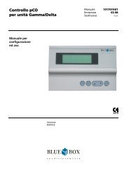
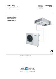
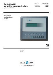
Unità ad espansione <strong>di</strong>retta con condesazione ad aria tipo O/UEDA - O/UEDA <strong>di</strong>rect expansion unit with <strong>air</strong> condensation<br />
Versione HH / HH Version<br />
1<br />
2<br />
3<br />
4<br />
Compressore tipo scroll<br />
Scroll compressor<br />
Batteria <strong>di</strong> raffreddamento<br />
Cool<strong>in</strong>g co<strong>il</strong><br />
Condensatore<br />
Condensers<br />
Post-riscaldamento elettrico<br />
Electrical post-heat<strong>in</strong>g<br />
5<br />
6<br />
7<br />
8<br />
Umi<strong>di</strong>ficatore ad elettro<strong>di</strong> immersi<br />
Electrode bo<strong>il</strong>er humi<strong>di</strong>fier<br />
Sezione motovent<strong>il</strong>ante<br />
Fan-motor section<br />
Controllo a microprocessore<br />
Microprocessor control<br />
Sezione f<strong>il</strong>trante<br />
F<strong>il</strong>ter section<br />
9<br />
Componenti circuiti frigo<br />
Refrigerant circuit components<br />
9a Ricevitore <strong>di</strong> liquido<br />
Liquid receiver<br />
9b Valvola termostatica<br />
Thermostatic valve<br />
9c Valvola solenoide<br />
Solenoid valve<br />
9d Spia liquido<br />
Liquid <strong>in</strong><strong>di</strong>cator<br />
9e F<strong>il</strong>tro freon<br />
Freon sta<strong>in</strong>er<br />
9f Pressostato <strong>di</strong> alta<br />
High pr. safety switch<br />
9g Pressostato <strong>di</strong> bassa<br />
Low pr. safety switch<br />
9h Rub<strong>in</strong>etti<br />
Cut-off valve<br />
T Sonda <strong>di</strong> temperatura<br />
Temperature probe<br />
U Sonda <strong>di</strong> umi<strong>di</strong>tà<br />
Humi<strong>di</strong>ty probe<br />
Environment protection<br />
All AIR BLUE products are produced<br />
accord<strong>in</strong>g to an environmentally friendly<br />
process. DAT’AIR <strong>air</strong> con<strong>di</strong>tioners have been<br />
designed to operate with ecologically friendly<br />
”halons free” refrigerants such as HFC<br />
R407C.
CRAX CRCF<br />
Batteria <strong>di</strong> raffreddamento 2 Cool<strong>in</strong>g co<strong>il</strong> 2<br />
Le batterie <strong>di</strong> raffreddamento sono del tipo The cool<strong>in</strong>g co<strong>il</strong> is made of copper tubes<br />
a pacco con tubi <strong>in</strong> rame ed alette <strong>in</strong><br />
and alum<strong>in</strong>ium f<strong>in</strong>s.<br />
allum<strong>in</strong>io. Alla base della batteria è <strong>in</strong>stallata At the foot of the co<strong>il</strong> a sta<strong>in</strong>less steel<br />
la bac<strong>in</strong>ella <strong>di</strong> raccolta dell’acqua <strong>di</strong><br />
condensate dra<strong>in</strong> pan complete with purge<br />
condensa, <strong>in</strong> acciaio <strong>in</strong>ossidab<strong>il</strong>e, completa<br />
<strong>di</strong> raccordo per lo scarico.<br />
is <strong>in</strong>stalled.<br />
3 3<br />
Condensatori<br />
Per le unità con condensazione ad aria sono<br />
previsti (forniti come accessorio) i<br />
condensatori remoti tipo CRAX (con<br />
vent<strong>il</strong>atori assiali) e/o CRCF (con vent<strong>il</strong>atori<br />
centrifughi).<br />
Per le unità con condensazione ad acqua,<br />
i condensatori sono del tipo a piastre<br />
saldobrasate <strong>in</strong> acciaio <strong>in</strong>ox AISI 316, montati<br />
<strong>di</strong> serie all’<strong>in</strong>terno dell’unità.<br />
Condensers<br />
For the <strong>air</strong>cooled units, a range (supplied as<br />
an accessory) of remote condensers<br />
designated “CRAX” (with axial fans)<br />
and “CRCF” (with centrifugal fans) have been<br />
designed.<br />
For the watercooled units, the condensers<br />
are sta<strong>in</strong>less steel AISI 316 brazed<br />
plate type and <strong>in</strong>stalled as standard.<br />
Post-riscaldamento elettrico 4 Electrical post-heat<strong>in</strong>g 4<br />
Le versioni CH e HH sono fornite <strong>di</strong> post- The CH and HH versions are equipped with<br />
riscaldamento elettrico costituito da batteria a re-heat<strong>in</strong>g function via an electric heat<strong>in</strong>g<br />
<strong>di</strong> resistenze elettriche con elementi riscaldanti element constructed from a non oxidable<br />
a bassa temperatura superficiale <strong>in</strong> materiale material.<br />
non ossidab<strong>il</strong>e.<br />
If overheat<strong>in</strong>g should occur, a safety<br />
In caso <strong>di</strong> surriscaldamento un termostato <strong>di</strong> thermostat cuts off the voltage supply to the<br />
sicurezza <strong>in</strong>terviene bloccando l'alimentazione<br />
elettrica alle resistenze e attivando un allarme.<br />
heaters and triggers an alarm.<br />
Sezione umi<strong>di</strong>ficazione 5<br />
Nella versione HH l'umi<strong>di</strong>ficazione è del tipo<br />
a elettro<strong>di</strong> immersi. Il controllo a microprocessore<br />
regola automaticamente la quantità <strong>di</strong> vapore, <strong>il</strong><br />
livello dell'acqua e la concentrazione sal<strong>in</strong>a nel<br />
bo<strong>il</strong>er; <strong>il</strong> funzionamento avviene con acqua <strong>di</strong><br />
alimentazione non trattata.<br />
Humi<strong>di</strong>fication section 5<br />
The humi<strong>di</strong>fication of the HH version is of the<br />
flooded electrodes type. The microprocessor<br />
automatically controls the steam quantity, the<br />
exact water level required and the sal<strong>in</strong>e<br />
concentration of water <strong>in</strong>to the bo<strong>il</strong>er.<br />
Operation is with non-treated feed<strong>in</strong>g water.<br />
Sezione motovent<strong>il</strong>ante 6 Fan-motor section 6<br />
M<strong>in</strong>idat 50÷80, Console 110÷170,<br />
M<strong>in</strong>idat 50÷80, Console 110÷170,<br />
Modular 100÷230, Bigdat 280÷460<br />
Modular 100÷230, Bigdat 280÷460<br />
Vent<strong>il</strong>atori centrifughi, a doppia aspirazione Double <strong>in</strong>let centrifugal fans conta<strong>in</strong><br />
con girante b<strong>il</strong>anciata staticamente e<br />
dynamically and statically balanced impellers,<br />
d<strong>in</strong>amicamente, accoppiata <strong>di</strong>rettamente al <strong>di</strong>rectly coupled with 6 pole electric motors<br />
motore elettrico a 6 poli.<br />
which reduce the wear of the belts.<br />
Il gruppo motovent<strong>il</strong>ante è montato su supporti The fan-motor group is <strong>in</strong>stalled on rubber<br />
antivibranti <strong>in</strong> gomma sulla bocca <strong>di</strong> mandata shock absorbers on the <strong>di</strong>scharge outlet and<br />
ed è completo <strong>di</strong> speciale prof<strong>il</strong>o elastico is complete with a special antivibration elastic<br />
antivibrante sul sistema <strong>di</strong> fissaggio al telaio. prof<strong>il</strong>e on the chassis fix<strong>in</strong>g system.<br />
AIR BLUE .9
10. AIR BLUE<br />
Modular 235÷520, Bigdat 600÷960,<br />
OFC-UFC 300÷1200<br />
Vent<strong>il</strong>atori centrifughi, a doppia aspirazione<br />
con girante b<strong>il</strong>anciata staticamente e<br />
d<strong>in</strong>amicamente. L’asse della girante ruota su<br />
cusc<strong>in</strong>etti a lubrificazione permanente.<br />
La girante a pale avanti e la coclea sono<br />
realizzate <strong>in</strong> acciaio galvanizzato.<br />
Nei modelli <strong>in</strong><strong>di</strong>cati la trasmissione avviene<br />
a mezzo <strong>di</strong> c<strong>in</strong>ghie e pulegge.<br />
Il motore elettrico, a 4 poli, è montato su un<br />
supporto regolab<strong>il</strong>e per ottenere una<br />
corretta tensione delle c<strong>in</strong>ghie <strong>di</strong><br />
trasmissione.<br />
Tutti i modelli possono essere forniti con<br />
vent<strong>il</strong>atori ad “alta prevalenza”.<br />
Allarme flusso aria<br />
Il flusso dell'aria <strong>in</strong> aspirazione del vent<strong>il</strong>atore<br />
è controllato costantemente da un<br />
pressostato <strong>di</strong>fferenziale ed attiva un allarme<br />
nella con<strong>di</strong>zione <strong>di</strong> mancanza flusso aria.<br />
Modular 235÷520, Bigdat 600÷960,<br />
OFC-UFC 300÷1200<br />
Double <strong>in</strong>let centrifugal fan with<br />
dynamically and statically balanced<br />
impeller.<br />
The impeller shaft is rotat<strong>in</strong>g on permanent<br />
lubricat<strong>in</strong>g bear<strong>in</strong>gs.<br />
The forward curved blade impeller and the<br />
volute are made of galvanized steel. In the<br />
above mentioned model the impeller is belt<br />
and pulley driven.<br />
The 4 pole electric motor, is <strong>in</strong>stalled on an<br />
adjustable support to tighten the belt<br />
correctly.<br />
All the models may be supplied on request<br />
with “high pressure” fans.<br />
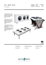
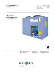
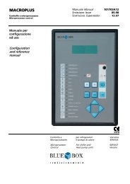
Unità ad espansione <strong>di</strong>retta con condensazione ad acqua tipo O/U ED W/R - O/U ED W/R <strong>di</strong>rect expansion unit with water condensation<br />
Versione HH / HH Version<br />
1<br />
2<br />
3<br />
4<br />
Compressore tipo scroll<br />
Scroll type compressor<br />
Batteria <strong>di</strong> raffreddamento<br />
Cool<strong>in</strong>g co<strong>il</strong><br />
Condensatore<br />
Condensers<br />
Post-riscaldamento elettrico<br />
Electrical post-heat<strong>in</strong>g<br />
5<br />
6<br />
7<br />
8<br />
Umi<strong>di</strong>ficatore ad elettro<strong>di</strong> immersi<br />
Electrode bo<strong>il</strong>er humi<strong>di</strong>fier<br />
Sezione motovent<strong>il</strong>ante<br />
Fan-motor section<br />
Controllo a microprocessore<br />
Microprocessor control<br />
Sezione f<strong>il</strong>trante<br />
F<strong>il</strong>ter section<br />
9<br />
Componenti circuiti frigo<br />
Refrigerant circuit components<br />
9a Ricevitore <strong>di</strong> liquido<br />
Liquid receiver<br />
9b Valvola termostatica<br />
Thermostatic valve<br />
9c Valvola solenoide<br />
Solenoid valve<br />
9d Spia liquido<br />
Liquid <strong>in</strong><strong>di</strong>cator<br />
9e F<strong>il</strong>tro freon<br />
Freon sta<strong>in</strong>er<br />
9f Pressostato <strong>di</strong> alta<br />
High pr. safety switch<br />
9g Pressostato <strong>di</strong> bassa<br />
Low pr. safety switch<br />
T Sonda <strong>di</strong> temperatura<br />
Temperature probe<br />
U Sonda <strong>di</strong> umi<strong>di</strong>tà<br />
Humi<strong>di</strong>ty probe<br />
Air flow alarm<br />
The fan suction <strong>air</strong> flow is permanently<br />
controlled by a <strong>di</strong>fferential pressure switch<br />
and triggers an alarm <strong>in</strong> case the <strong>air</strong> flow is<br />
lack<strong>in</strong>g.
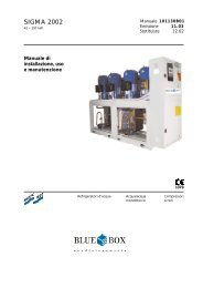
Unità ad acqua refrogerata tipo O/U FC - O/U FC ch<strong>il</strong>led water unit<br />
Versione HH / HH Version<br />
2<br />
4<br />
5<br />
6<br />
7<br />
8<br />
10<br />
Batteria <strong>di</strong> raffreddamento<br />
Cool<strong>in</strong>g co<strong>il</strong><br />
Post-riscaldamento elettrico<br />
Electrical post-heat<strong>in</strong>g<br />
Umi<strong>di</strong>ficatore ad elettro<strong>di</strong> immersi<br />
Electrode bo<strong>il</strong>er humi<strong>di</strong>fier<br />
Sezione motovent<strong>il</strong>ante<br />
Fan-motor section<br />
Controllo a microprocessore<br />
Microprocessor control<br />
Sezione f<strong>il</strong>trante<br />
F<strong>il</strong>ter section<br />
Valvola a 3 vie flottante<br />
Motorised 3 way valve<br />
T Sonda <strong>di</strong> temperatura<br />
Temperature probe<br />
U Sonda <strong>di</strong> umi<strong>di</strong>tà<br />
Humi<strong>di</strong>ty probe<br />
a. L’unità <strong>in</strong> stand-by entrerà<br />
<strong>in</strong> funzione con presenza<br />
<strong>di</strong> allarme critico per una delle<br />
unità <strong>in</strong> funzionamento.<br />
a. The unit on stand-by w<strong>il</strong>l come<br />
<strong>in</strong>to operation when there is<br />
a crucial alarm for one of the<br />
units <strong>in</strong> operation.<br />
Controllo a microprocessore<br />
La regolazione delle con<strong>di</strong>zioni ambientali e la<br />
gestione delle funzioni <strong>di</strong> monitoraggio dei<br />
con<strong>di</strong>zionatori <strong>Dat</strong>’Air avvengono attraverso<br />
un controllo a microprocessore. Con l’ut<strong>il</strong>izzo<br />
<strong>di</strong> microprocessori ad elevate prestazioni Air<br />
Blue è <strong>in</strong> <strong>grado</strong> <strong>di</strong> sod<strong>di</strong>sfare esigenze <strong>di</strong><br />
regolazione tra le più complesse.<br />
• Con <strong>il</strong> microprocessore “parametrico”<br />
MACROLOGIC Air Blue offre un controllo<br />
semplice, economico ed affidab<strong>il</strong>e <strong>in</strong> <strong>grado</strong> <strong>di</strong><br />
gestire le funzioni <strong>di</strong> raffreddamento,<br />
riscaldamento e deumi<strong>di</strong>fica (questo controllo<br />
viene <strong>in</strong>stallato <strong>di</strong> serie su tutte le unità <strong>in</strong><br />
versione CO e CH). Una serie <strong>di</strong> icone “user<br />
friendly” visualizzano gli stati <strong>di</strong><br />
funzionamento dell’unità e un segnale<br />
acustico avvisa l’utente <strong>in</strong> caso <strong>di</strong> allarme.<br />
• Con <strong>il</strong> microprocessore “programmab<strong>il</strong>e”<br />
DATALOGIC2 Microprocessor control<br />
Adjustment of ambient con<strong>di</strong>tions and<br />
management of monitor<strong>in</strong>g functions of <strong>Dat</strong>’<br />
Air <strong>air</strong> con<strong>di</strong>tioners are performed by means of<br />
a microprocessor controller. Thanks to the use<br />
of high performance microprocessors, Air Blue<br />
is capable of meet<strong>in</strong>g the most sophisticated<br />
requirements of end users.<br />
With the MACROLOGIC parametric<br />
microprocessor, Air Blue offers a simple,<br />
economic, and reliable method of controll<strong>in</strong>g<br />
cool<strong>in</strong>g, heat<strong>in</strong>g, humi<strong>di</strong>fication, and<br />
dehumi<strong>di</strong>fication functions (this type of<br />
controller is <strong>in</strong>stalled as standard on all units <strong>in</strong><br />
CO and CH versions). The operat<strong>in</strong>g states of<br />
the unit are shown by means of user-friendly<br />
icons, wh<strong>il</strong>e alarm warn<strong>in</strong>gs are provided by<br />
means of an au<strong>di</strong>ble signal.<br />
• With the DATALOGIC<br />
Air Blue offre <strong>in</strong>vece un<br />
controllo <strong>in</strong> <strong>grado</strong> <strong>di</strong> gestire algoritmi <strong>di</strong><br />
regolazione complessi e strategie <strong>di</strong> controllo<br />
particolari.<br />
2 7 7<br />
programmable<br />
microprocessor, Air Blue offers a control<br />
system capable of adm<strong>in</strong>ister<strong>in</strong>g complex<br />
control algorithms and highly specific control<br />
strategies.<br />
AIR BLUE .11
. La rotazione oraria permette<br />
<strong>di</strong> avere le stesse ore <strong>di</strong><br />
funzionamento tra le varie unità.<br />
b. The clockwise rotation makes<br />
it possible to have the same hours<br />
of operation for all the various<br />
units.<br />
12. AIR BLUE<br />
- In abb<strong>in</strong>amento ad un <strong>di</strong>splay LCD 4 righe per<br />
20 colonne vengono estese le potenzialità del<br />
controllo MACROLOGIC. Le unità dotate <strong>di</strong><br />
DATALOGIC 2 (<strong>in</strong>stallato <strong>di</strong> serie su tutte<br />
le unità <strong>in</strong> versione HH) possono essere<br />
connesse <strong>in</strong> rete locale, la LAN (Local Area<br />
Network) così costruita può avere f<strong>in</strong>o a 16<br />
unità <strong>Dat</strong>’Air collegate, <strong>di</strong> queste f<strong>in</strong>o a 3<br />
possono essere lasciate <strong>in</strong> stand-by. Queste<br />
ultime entrano <strong>in</strong> funzione <strong>in</strong> caso <strong>di</strong> allarme<br />
critico su una delle unità <strong>in</strong> runn<strong>in</strong>g oppure <strong>in</strong><br />
appoggio alle prime per sod<strong>di</strong>sfare con<strong>di</strong>zioni<br />
<strong>di</strong> carico particolarmente gravose. Il controllo<br />
permette <strong>di</strong> gestire la rotazione oraria per<br />
avere le stesse ore <strong>di</strong> funzionamento tra le<br />
unità. La LAN può essere costruita senza<br />
l’aus<strong>il</strong>io <strong>di</strong> hardware aggiuntivo <strong>in</strong> quanto un<br />
orologio e una scheda <strong>di</strong> <strong>in</strong><strong>di</strong>rizzamento sono<br />
già presenti <strong>di</strong> serie.<br />
La presenza <strong>di</strong> un orologio consente <strong>di</strong><br />
memorizzare la data e l’ora <strong>di</strong> 150 con<strong>di</strong>zioni <strong>di</strong><br />
allarme. Lo storico allarmi viene completato<br />
dalla memorizzazione del co<strong>di</strong>ce e dalla<br />
descrizione dell’allarme <strong>in</strong>tervenuto.<br />
Il controllo DATALOGIC 2 consente poi <strong>di</strong> gestire<br />
la logica delle unità con allestimento DUAL<br />
COOLING.<br />
- In abb<strong>in</strong>amento ad un term<strong>in</strong>ale grafico<br />
(fornito come accessorio) <strong>di</strong> 16 righe per 30<br />
colonne <strong>il</strong> controllo DATALOGIC 2 consente <strong>di</strong><br />
monitorare l’unità <strong>Dat</strong>’Air per avere un’idea del<br />
suo comportamento nel tempo. Tutti i valori <strong>di</strong><br />
temperatura ed umi<strong>di</strong>tà r<strong>il</strong>evati dai sensori<br />
<strong>in</strong>stallati possono essere visualizzati attraverso<br />
grafici con scala dei tempi oraria, giornaliera o<br />
settimanale. Attraverso delle icone d<strong>in</strong>amiche<br />
“user friendly” è possib<strong>il</strong>e visualizzare lo stato<br />
<strong>di</strong> funzionamento dell’unità.<br />
- Il controllo DATALOGIC 2 attraverso l’ut<strong>il</strong>izzo <strong>di</strong><br />
una scheda potenziata (fornita come<br />
accessorio), <strong>in</strong> abb<strong>in</strong>amento sia al term<strong>in</strong>ale<br />
LCD che grafico, consente <strong>il</strong> riporto a <strong>di</strong>stanza<br />
attraverso contatti puliti esterni <strong>di</strong> 5 allarmi e/o<br />
- In conjunction with a 4 l<strong>in</strong>e / 20 column<br />
LCD <strong>di</strong>splay, the capab<strong>il</strong>ities of the<br />
MACROLOGIC controller are extended<br />
significantly. Units equipped with<br />
DATALOGIC 2 (<strong>in</strong>stalled as standard on all HH<br />
version units) can be connected <strong>in</strong> a local<br />
area network to create a LAN with up to 16<br />
<strong>in</strong>terconnected <strong>Dat</strong>’Air units of which three<br />
can be on stand-by. The units on stand-by<br />
w<strong>il</strong>l come <strong>in</strong>to operation <strong>in</strong> the event of a<br />
critical alarm on one of the operat<strong>in</strong>g units or<br />
to support the other units to meet<br />
particularly severe heat<strong>in</strong>g/cool<strong>in</strong>g demands.<br />
The controller provides a rotation system that<br />
allows all the units <strong>in</strong> the LAN to accumulate<br />
the same number of duty hours. The LAN to<br />
can be created without the use of ad<strong>di</strong>tional<br />
hardware, as a clock and an address card<br />
<strong>in</strong>cluded as standard equipment.<br />
The presence of a clock makes it possible to<br />
store the date and time of some 150<br />
<strong>di</strong>fferent alarm con<strong>di</strong>tions. The alarms historic<br />
database is completed by sav<strong>in</strong>g the alarm<br />
code and a description of the type of alarm.<br />
The DATALOGIC 2 controller also makes it<br />
possible to control the operat<strong>in</strong>g logic of<br />
DUAL COOLING type units.<br />
- In conjunction with a 16 l<strong>in</strong>e / 30 column<br />
graphic term<strong>in</strong>al (supplied as an accessory),<br />
the DATALOGIC 2 controller makes it possible<br />
to monitor the <strong>Dat</strong>’Air unit and obta<strong>in</strong><br />
<strong>in</strong>formation regard<strong>in</strong>g its behaviour through<br />
the course of time. All temperature and<br />
humi<strong>di</strong>ty values read by the <strong>in</strong>stalled sensors<br />
can be viewed by means of graphics with<br />
time scales <strong>in</strong> hours, days, or weeks. The<br />
operat<strong>in</strong>g status of the unit is shown by a<br />
series of dynamic user-friendly icons.<br />
- By means of an enhanced function card<br />
(supplied as an accessory), <strong>in</strong> conjunction with<br />
the LCD term<strong>in</strong>al and graphic term<strong>in</strong>al, the<br />
DATALOGIC 2 controller provides the fac<strong>il</strong>ity for<br />
remote signall<strong>in</strong>g, on external voltage-free
stati <strong>di</strong> funzionamento dell’unità. Per sod<strong>di</strong>sfare<br />
le <strong>di</strong>verse esigenze del cliente queste 5<br />
segnalazioni possono essere impostate via<br />
software dall’utente stesso selezionandole da<br />
una lista predef<strong>in</strong>ita.<br />
Collegamento a sistemi <strong>di</strong><br />
supervisione, BMS<br />
Nell’ottica <strong>di</strong> una comunicazione globale tutti<br />
i microprocessori Air Blue possono essere<br />
connessi ad un network per potere,<br />
attraverso un sistema <strong>di</strong> supervisione,<br />
“parlare” tra <strong>di</strong> loro. Le possib<strong>il</strong>ità offerte<br />
sono tra le più svariate e vanno da un<br />
supervisore con protocollo <strong>di</strong> comunicazione<br />
“proprietario” denom<strong>in</strong>ato “DATA PLANT”<br />
alla possib<strong>il</strong>ità <strong>di</strong> <strong>in</strong>terfacciamento con i più<br />
<strong>di</strong>ffusi protocolli <strong>di</strong> comunicazione “non<br />
proprietari” quali ModBus, Echelon, BacNet,<br />
Metasys.<br />
La trasmissione dei dati avviene attraverso<br />
l<strong>in</strong>ea seriale RS485 e, nel caso <strong>di</strong> ut<strong>il</strong>izzo del<br />
controllo DATALOGIC 2 , molto spesso non<br />
sono necessari gateway esterni <strong>in</strong> quanto i<br />
protocolli vengono memorizzati nella<br />
memoria stessa del sistema (verificare con<br />
l’ufficio tecnico Air Blue i protocolli<br />
<strong>di</strong>sponib<strong>il</strong>i). Attraverso un <strong>di</strong>spositivo<br />
denom<strong>in</strong>ato DATA WATCH ed un modem<br />
GSM esterno è poi possib<strong>il</strong>e far comunicare i<br />
microprocessori Air Blue con le più comuni<br />
periferiche <strong>di</strong> trasmissione dati quali<br />
stampanti, fax e telefon<strong>in</strong>i cellulari. Un<br />
messaggio SMS <strong>di</strong> allarme può essere <strong>in</strong>viato<br />
ad uno o più centri <strong>di</strong> assistenza.<br />
Quadro elettrico<br />
Costruito secondo le norme VDE (Verband<br />
Deutscher Elektrotechniker) e IEC ragruppa tutti<br />
i componenti necessari per <strong>il</strong> funzionamento<br />
automatico dell'unità: <strong>il</strong> sezionatore generale,<br />
contattori, protezioni magnetotermiche, relè<br />
sequenza fase (solo su unità con alimentazione<br />
trifase) e tutti gli organi <strong>di</strong> sicurezza. I circuiti<br />
aus<strong>il</strong>iari sono a tensione 24V. Il quadro elettrico<br />
è alloggiato <strong>in</strong> un vano separato dal flusso<br />
dell'aria, fac<strong>il</strong>mente accessib<strong>il</strong>e dal fronte della<br />
macch<strong>in</strong>a, consentendo <strong>in</strong> tal modo, un rapido<br />
controllo generale.<br />
contacts, of five alarms and/or operat<strong>in</strong>g<br />
statuses. To meet the vary<strong>in</strong>g demands of endusers,<br />
these five <strong>in</strong><strong>di</strong>cations can be set via<br />
software by the user, who makes the required<br />
selections from a preset list.<br />
Connection to BMS supervision<br />
systems<br />
In the framework of global communications, all<br />
Air Blue microprocessors may be connected<br />
together <strong>in</strong> a network via a supervision system<br />
where they are able to exchange <strong>in</strong>formation<br />
and “speak” to each other. The fac<strong>il</strong>ities offered<br />
are extremely <strong>di</strong>verse, from a supervisor with a<br />
proprietary communication protocol,<br />
designated “DATA PLANT”, to the possib<strong>il</strong>ity of<br />
<strong>in</strong>terfac<strong>in</strong>g with the most widely used nonproprietary<br />
communication protocols, namely<br />
ModBus, Echelon, BacNet, and Metasys. <strong>Dat</strong>a<br />
transmission takes place on an RS485 serial<br />
l<strong>in</strong>e. When the DATALOGIC 2 is ut<strong>il</strong>ised, it is<br />
often not necessary to use external gateways<br />
as the protocols are saved <strong>di</strong>rectly on the<br />
system’s <strong>in</strong>ternal memory (it is necessary to<br />
verify with Air Blue which protocols are<br />
ava<strong>il</strong>able).<br />
By means of a device designated DATA WATCH<br />
and an external GSM modem, it is possible to<br />
place the Air Blue microprocessors <strong>in</strong><br />
communication with the most commonly<br />
used data transmission peripheral devices such<br />
as pr<strong>in</strong>ters, fax mach<strong>in</strong>es and mob<strong>il</strong>e phones.<br />
In ad<strong>di</strong>tion, SMS alarm messages can be<br />
transmitted to one or more service centres<br />
if so required.<br />
Electric switch board<br />
In accordance with VDE (Verband Deutscher<br />
Elektrotechniker) and IEC standards, all the<br />
components necessary for the automatic<br />
operation of the unit are <strong>in</strong>cluded: the ma<strong>in</strong><br />
switch, the contactors, the automatic circuit<br />
breakers, sequence phase relay (only <strong>in</strong><br />
three phase supply units) and all safety<br />
devices. Aux<strong>il</strong>iary circuits are 24 Volts. The<br />
electric switch board is housed <strong>in</strong> a vane<br />
which is separated from the <strong>air</strong> flow and is<br />
eas<strong>il</strong>y accessible from the front of the unit,<br />
allow<strong>in</strong>g a quick check whenever required.<br />
Sezione f<strong>il</strong>trante <strong>di</strong> elevata efficienza 8 High efficiency f<strong>il</strong>ter section 8<br />
I f<strong>il</strong>tri a secco <strong>in</strong> materiale s<strong>in</strong>tetico, con <strong>grado</strong> Wide <strong>air</strong> passage area dry synthetic<br />
<strong>di</strong> efficienza EU4, <strong>in</strong>seriti <strong>in</strong> un telaio <strong>di</strong> lamiera f<strong>il</strong>ters of EU4 grad<strong>in</strong>g, bu<strong>il</strong>t-<strong>in</strong> a galvanized<br />
z<strong>in</strong>cata con ampia superficie <strong>di</strong> passaggio aria, sheet iron (on request high efficiency<br />
(su richiesta sono previsti f<strong>il</strong>tri ad alta efficienza f<strong>il</strong>ters of EU 5 grad<strong>in</strong>g), are fitted.<br />
con <strong>grado</strong> <strong>di</strong> f<strong>il</strong>trazione EU5). La rimozione dei F<strong>il</strong>ters are removable from the front of the<br />
f<strong>il</strong>tri si effettua dal fronte dell'unità.<br />
unit.<br />
AIR BLUE .13
9a 9f<br />
9b 9g<br />
9c 9h<br />
9d 9i<br />
9e 9l<br />
14. AIR BLUE<br />
Componenti circuito frigorifero 9 Refrigerant circuit components 9<br />
(unità <strong>di</strong> tipo *ED*)<br />
(*ED* type unit)<br />
Ogni circuito frigorifero comprende:<br />
Each refrigerant circuit <strong>in</strong>cludes:<br />
-ricevitore <strong>di</strong> liquido (9a)<br />
- liquid receiver (9a)<br />
- valvola <strong>di</strong> espansione termostatica completa - thermostatic expansion valve complete<br />
<strong>di</strong> equalizzatore esterno e <strong>di</strong> vite<br />
with external equalizer and micromatic<br />
micrometrica <strong>di</strong> taratura (9b)<br />
adjust<strong>in</strong>g screw (9b)<br />
- valvola a solenoide per l'<strong>in</strong>tercettazione del - liquid l<strong>in</strong>e solenoid valve (only units<br />
liquido frigorigeno (solo modelli *EDA) (9c) *EDA) (9c)<br />
- <strong>in</strong><strong>di</strong>catore <strong>di</strong> passaggio del liquido<br />
- refrigerant liquid <strong>in</strong><strong>di</strong>cator (9d)<br />
frigorigeno (9d)<br />
- molecular mesh freon stra<strong>in</strong>er (9e)<br />
- f<strong>il</strong>tro freon a setacci molecolari (9e) - manual reset high pressure safety<br />
-pressostato <strong>di</strong> sicurezza <strong>di</strong> alta pressione switch (9f)<br />
a reset manuale (9f)<br />
- automatic reset low pressure safety<br />
-pressostato <strong>di</strong> sicurezza <strong>di</strong> bassa pressione switch (9g)<br />
a reset automatico (9g)<br />
- shut off valve for external connections (9h)<br />
-rub<strong>in</strong>etti <strong>di</strong> <strong>in</strong>tercettazione per connessioni - refrigerant copper tubes with <strong>in</strong>sulation<br />
esterne (9h)<br />
on the suction l<strong>in</strong>e to prevent condensate<br />
- tubazioni frigorifere <strong>in</strong> rame con isolamento formation (9i)<br />
anticondensa sulla l<strong>in</strong>ea <strong>di</strong> aspirazione (9i) - flexible hoses for pressure switch<br />
- tubazioni flessib<strong>il</strong>i per <strong>il</strong> raccordo dei<br />
pressostati (9l)<br />
connections (9l)<br />
Componenti circuito idraulico 10 Hydraulic circuit components 10<br />
(OFC-UFC)<br />
(OFC-UFC)<br />
Una valvola a 3 vie flottante, provvede a A float<strong>in</strong>g 3 way valve performs the control<br />
controllare le con<strong>di</strong>zioni ambientali dosando <strong>il</strong> of ambient con<strong>di</strong>tions measur<strong>in</strong>g the<br />
flusso dell'acqua che attraversa la batteria <strong>di</strong> water flow which is flow<strong>in</strong>g <strong>in</strong>to the heat<br />
scambio.<br />
exchange co<strong>il</strong>.
Allestimenti<br />
<strong>di</strong>sponib<strong>il</strong>i<br />
Configurations<br />
ava<strong>il</strong>able<br />
Unità SC<br />
Le unità con allestimento SC conservano<br />
tutte le caratteristiche delle unità con<br />
allestimento base. A <strong>di</strong>fferenza <strong>di</strong> queste,<br />
sono prive del compressore/i e dei relativi<br />
pressostati <strong>di</strong> sicurezza <strong>di</strong> alta e bassa<br />
pressione. A livello <strong>di</strong> quadro elettrico<br />
vengono tolte le protezioni relative al<br />
compressore e <strong>il</strong> relè sequenza fase (per i<br />
modelli trifase). Queste unità sono<br />
particolarmente <strong>in</strong><strong>di</strong>cate ad essere accoppiate<br />
con le motocondensanti Air Blue della serie<br />
ALFA LE.<br />
Unità DC<br />
Le unità con allestimento Dual Cool<strong>in</strong>g sono<br />
dotate <strong>di</strong> due batterie; una ad espansione<br />
<strong>di</strong>retta collegata ad un compressore <strong>in</strong>terno<br />
alla macch<strong>in</strong>a ed una ad acqua refrigerata, <strong>di</strong><br />
norma collegata ad un refrigeratore d’acqua<br />
esterno. La batteria ad acqua refrigerata è<br />
quella normalmente <strong>in</strong> funzione. Un<br />
flussostato e una sonda <strong>di</strong> temperatura posti<br />
<strong>in</strong> <strong>in</strong>gresso alla batteria stab<strong>il</strong>iscono quando <strong>il</strong><br />
funzionamento deve essere passato alla<br />
batteria ad espansione <strong>di</strong>retta.<br />
Le con<strong>di</strong>zioni che fanno attivare la batteria ad<br />
espansione <strong>di</strong>retta (e qu<strong>in</strong><strong>di</strong> <strong>il</strong> compressore)<br />
sono le seguenti:<br />
• mancanza <strong>di</strong> un flusso d’ acqua<br />
refrigerata;<br />
• temperatura dell’acqua refrigerata al <strong>di</strong><br />
sopra <strong>di</strong> un valore impostab<strong>il</strong>e;<br />
• carico termico ambiente non sod<strong>di</strong>sfatto<br />
dalla sola batteria ad acqua (la batteria ad<br />
espansione <strong>di</strong>retta agisce come grad<strong>in</strong>o <strong>di</strong><br />
freddo aggiuntivo, una sonda <strong>di</strong><br />
temperatura posta a valle delle due<br />
batterie impe<strong>di</strong>sce <strong>il</strong> funzionamento <strong>in</strong><br />
caso <strong>di</strong> temperatura dell’aria <strong>in</strong> uscita dalle<br />
batterie troppo fredda). Questa funzione<br />
può essere <strong>di</strong>sab<strong>il</strong>itata via software.<br />
Nel funzionamento dell’unità si possono<br />
<strong>in</strong><strong>di</strong>viduare i seguenti mo<strong>di</strong> <strong>di</strong> operare:<br />
1. Refrigeratore d’acqua attivo (ovvero<br />
presenza <strong>di</strong> acqua refrigerata con una<br />
temperatura <strong>in</strong>feriore ad un valore<br />
impostato) e set <strong>di</strong> temperatura non<br />
sod<strong>di</strong>sfatto.<br />
Il vent<strong>il</strong>atore dell’unità è attivo, <strong>il</strong><br />
compressore è spento, mentre la valvola a<br />
tre vie modula la portata <strong>di</strong> acqua<br />
refrigerata attraverso la batteria per<br />
v<strong>in</strong>cere <strong>il</strong> carico termico ambiente. Solo nel<br />
caso <strong>in</strong> cui la batteria ad acqua refrigerata<br />
non sia <strong>in</strong> <strong>grado</strong> <strong>di</strong> sod<strong>di</strong>sfare<br />
completamente <strong>il</strong> carico, <strong>il</strong> compressore<br />
viene attivato (se la funzione é ab<strong>il</strong>itata).<br />
SC Units<br />
Units with SC configurations have all the<br />
characteristics of units with the basic<br />
configuration. They <strong>di</strong>ffer from the basic<br />
units, however, because they are not<br />
equipped with the compressor/s and relative<br />
safety high and low pressure switches. In this<br />
case, the electrical panel does not have the<br />
electrical protection for the compressor and<br />
the phase sequence relay (for three phase<br />
models).These units are particularly suitable<br />
for use <strong>in</strong>comb<strong>in</strong>ation with Air Blue<br />
condens<strong>in</strong>g units from the ALFA LE series.<br />
DC Units<br />
The Dual Cool<strong>in</strong>g unit is fitted with two co<strong>il</strong>s;<br />
one <strong>di</strong>rect expansion co<strong>il</strong> connected to a<br />
compressor <strong>in</strong>side the unit and one ch<strong>il</strong>led<br />
water co<strong>il</strong> connected to an external water<br />
ch<strong>il</strong>ler; the latter is the one normally<br />
operat<strong>in</strong>g. The flowswitch and temperature<br />
probe at the co<strong>il</strong> <strong>in</strong>let determ<strong>in</strong>e when the<br />
operation should change to the <strong>di</strong>rect<br />
expansion co<strong>il</strong>.<br />
The <strong>di</strong>rect expansion co<strong>il</strong> (and the<br />
compressor) is activated <strong>in</strong> the event of the<br />
follow<strong>in</strong>g con<strong>di</strong>tions:<br />
• no ch<strong>il</strong>led water flow;<br />
• ch<strong>il</strong>led water temperature above set value;<br />
• ambient thermal load is not satisfied by<br />
the ch<strong>il</strong>led water co<strong>il</strong> operation only (the<br />
<strong>di</strong>rect expansion co<strong>il</strong> acts as an ad<strong>di</strong>tional<br />
cool<strong>in</strong>g step; a temperature probe at the<br />
co<strong>il</strong> delivery <strong>in</strong>hibits operation <strong>in</strong> the event<br />
that the <strong>air</strong> temperature at the co<strong>il</strong> outlet<br />
is too low). This function can be <strong>di</strong>sabled<br />
via the control software.<br />
The unit operates <strong>in</strong> the follow<strong>in</strong>g modes:<br />
1. Water ch<strong>il</strong>ler active (i.e. ch<strong>il</strong>led water<br />
present when temperature is lower than<br />
sett<strong>in</strong>g) and temperature sett<strong>in</strong>g not<br />
reached.<br />
In this mode, the unit fan is active, the<br />
compressor is off, wh<strong>il</strong>e the 3-way valve<br />
modulates ch<strong>il</strong>led water flow through the<br />
co<strong>il</strong> to meet the ambient thermal load.<br />
The compressor is activated only <strong>in</strong> the<br />
event that the ch<strong>il</strong>led water co<strong>il</strong> is unable<br />
to satisfy the load completely (if the<br />
function is not <strong>di</strong>sabled).<br />
AIR BLUE .15
16. AIR BLUE<br />
2. Refrigeratore d’acqua attivo (ovvero<br />
presenza <strong>di</strong> acqua refrigerata con una<br />
temperatura <strong>in</strong>feriore ad un certo valore<br />
impostato) e set <strong>di</strong> temperatura<br />
sod<strong>di</strong>sfatto<br />
Il vent<strong>il</strong>atore dell’unità è attivo <strong>il</strong><br />
compressore è spento e la valvola a tre vie<br />
impe<strong>di</strong>sce alla portata d’ acqua <strong>di</strong> passare<br />
attraverso la batteria.<br />
3. Refrigeratore d’acqua spento (ovvero non<br />
c’è presenza <strong>di</strong> acqua refrigerata o la<br />
temperatura dell’acqua è superiore ad un<br />
certo valore impostato) e set <strong>di</strong><br />
temperatura non sod<strong>di</strong>sfatto.<br />
2. Water ch<strong>il</strong>ler active (i.e. ch<strong>il</strong>led water<br />
present when temperature is lower than<br />
sett<strong>in</strong>g) and temperature sett<strong>in</strong>g reached.<br />
In this mode, the unit fan is active, the<br />
compressor is off, wh<strong>il</strong>e the 3-way valve<br />
<strong>in</strong>hibits ch<strong>il</strong>led water flow through the<br />
co<strong>il</strong>.<br />
3. Water ch<strong>il</strong>ler off (i.e. no ch<strong>il</strong>led water<br />
present or water temperature is higher<br />
than sett<strong>in</strong>g) and temperature sett<strong>in</strong>g not<br />
reached.<br />
Unità ad espansione <strong>di</strong>retta <strong>in</strong> allestimento Dual Cool<strong>in</strong>g tipo O/U EDA DC - O/U EDA DC <strong>di</strong>rect expansion unit Dual Cool<strong>in</strong>g<br />
Versione HH / HH Version<br />
1<br />
2<br />
4<br />
5<br />
6<br />
Compressore tipo scroll<br />
Scroll type compressor<br />
Batterie <strong>di</strong> raffreddamento<br />
Cool<strong>in</strong>g co<strong>il</strong>s<br />
Post-riscaldamento elettrico<br />
Electrical post-heat<strong>in</strong>g<br />
Umi<strong>di</strong>ficatore ad elettro<strong>di</strong> immersi<br />
Electrode bo<strong>il</strong>er humi<strong>di</strong>fier<br />
Sezione motovent<strong>il</strong>ante<br />
Fan-motor section<br />
7<br />
8<br />
9<br />
Controllo a microprocessore<br />
Microprocessor control<br />
Sezione f<strong>il</strong>trante<br />
F<strong>il</strong>ter section<br />
Componenti circuiti frigo<br />
Refrigerant circuit components<br />
9a Ricevitore <strong>di</strong> liquido<br />
Liquid receiver<br />
9b Valvola termostatica<br />
Thermostatic valve<br />
9c Valvola solenoide<br />
Solenoid valve<br />
9d Spia liquido<br />
Liquid <strong>in</strong><strong>di</strong>cator<br />
9e F<strong>il</strong>tro freon<br />
Freon sta<strong>in</strong>er<br />
9f Pressostato <strong>di</strong> alta<br />
High pr. safety switch<br />
9g Pressostato <strong>di</strong> bassa<br />
Low pr. safety switch<br />
9h Rub<strong>in</strong>etti<br />
Cut-off valve<br />
10<br />
11<br />
Valvola a 3 vie flottante<br />
Motorised 3 way valve<br />
Flussostato<br />
Flow switch<br />
T Sonda <strong>di</strong> temperatura - Temperature probe<br />
U Sonda <strong>di</strong> umi<strong>di</strong>tà - Humi<strong>di</strong>ty probe<br />
BTR Sonda temperatura Ripresa<br />
Return <strong>air</strong> temp. probe<br />
BTM Sonda temperatura Mandata<br />
Supply <strong>air</strong> temp. probe<br />
BTR Sonda temperatura Acqua<br />
Water temp. probe
Il vent<strong>il</strong>atore dell’unità è attivo, la valvola a<br />
tre vie si trova <strong>in</strong> posizione <strong>di</strong> chiusura<br />
mentre <strong>il</strong> compressore è attivo per v<strong>in</strong>cere<br />
<strong>il</strong> carico termico ambiente.<br />
4. Refrigeratore d’acqua spento (ovvero non<br />
c’è presenza <strong>di</strong> acqua refrigerata o la<br />
temperatura dell’acqua è superiore ad un<br />
certo valore impostato) e set <strong>di</strong> temperatura<br />
sod<strong>di</strong>sfatto. In questo caso entrambe le<br />
sorgenti <strong>di</strong> freddo sono <strong>di</strong>sattivate e solo i<br />
vent<strong>il</strong>atori risultano <strong>in</strong> funzione.<br />
Nel caso <strong>di</strong> unità HH, l’azione <strong>di</strong><br />
deumi<strong>di</strong>fica viene svolta solo dalla<br />
sorgente fredda attiva <strong>in</strong> quel momento.<br />
Rispetto all’unità tipo *ED* con allestimento<br />
base sono presenti i seguenti componenti<br />
aggiuntivi:<br />
• batteria ad acqua refrigerata<br />
• valvola a tre vie <strong>di</strong> tipo modulante tramite<br />
segnale elettrico 0 ÷ 10 Vdc<br />
• un flussostato a paletta ed una sonda <strong>di</strong><br />
temperatura tipo NTC<br />
In queste unità, per qualunque tipologia CO<br />
CH o HH, viene sempre <strong>in</strong>stallato <strong>il</strong> controllo<br />
a microprocessore DATALOGIC 2 .<br />
Unità RP<br />
Le unità con allestimento RP sono <strong>di</strong> tipo<br />
OVER (mandata verso l’alto) con ripresa<br />
posteriore anziché frontale. Sono<br />
particolarmente <strong>in</strong><strong>di</strong>cate per essere ut<strong>il</strong>izzate<br />
quando l’aria <strong>di</strong> ripresa proviene da canali.<br />
In this mode, the unit fan is active, the 3way<br />
valve <strong>in</strong>hibits ch<strong>il</strong>led water flow<br />
through the co<strong>il</strong> wh<strong>il</strong>e the compressor is<br />
activated to meet the ambient thermal load.<br />
4. water ch<strong>il</strong>ler off (i.e. no ch<strong>il</strong>led water<br />
present or water temperature is greater<br />
than sett<strong>in</strong>g) and temperature sett<strong>in</strong>g<br />
reached.<br />
In this mode, both cool<strong>in</strong>g sources are<br />
deactivated, fans only are operat<strong>in</strong>g.<br />
For “HH” version units, dehumi<strong>di</strong>fication is<br />
only carried out by the cool<strong>in</strong>g source<br />
activated at the time.<br />
With respect to *ED* type units <strong>in</strong> the basic<br />
configuration, the follow<strong>in</strong>g equipment is present:<br />
• ch<strong>il</strong>led water co<strong>il</strong><br />
• three-way valve modulated by an 0 - 10<br />
Vdc signal<br />
• vane flowswitch and NTC temperature<br />
probe<br />
In these units, irrespective of type (CO, CH<br />
or HH), the DATALOGIC 2 microprocessor<br />
controller is always <strong>in</strong>stalled.<br />
RP Units<br />
Units with RP configuration are of the OVER<br />
type (with upward <strong>air</strong> delivery) with rear <strong>air</strong><br />
<strong>in</strong>take rather than front <strong>air</strong> <strong>in</strong>take.<br />
These units are particularly suitable for use <strong>in</strong><br />
<strong>in</strong>stallations where the <strong>in</strong>take <strong>air</strong> is ducted.<br />
AIR BLUE .17
Accessori<br />
Accessories<br />
18. AIR BLUE<br />
Controllo velocità vent<strong>il</strong>atori<br />
dei condensatori assiali CRAX tramite<br />
regolatore elettronico che permette una<br />
corretta condensazione con temperature<br />
ambiente esterno f<strong>in</strong>o a -20°C.<br />
Low ambient kit<br />
con serrande per condensatori centrifughi<br />
CRCF.<br />
S<strong>il</strong>enziatore su mandata e<br />
aspirazione<br />
per condensatori centrifughi CRCF.<br />
F<strong>il</strong>tri ad alta efficienza<br />
con <strong>grado</strong> <strong>di</strong> f<strong>il</strong>trazione EU5.<br />
Post-riscaldamento ad acqua<br />
Costituito da batteria realizzata con tubi <strong>di</strong><br />
rame ed alette <strong>in</strong> allum<strong>in</strong>io dotata <strong>di</strong> valvola a<br />
3vie on/off preassemblata.<br />
Presa aria <strong>di</strong> r<strong>in</strong>novo<br />
corredata <strong>di</strong> f<strong>il</strong>tro e collare per collegamento<br />
a condotto flessib<strong>il</strong>e.<br />
Plenum <strong>di</strong> ripresa e mandata<br />
(non previsto su MINIDAT UNDER) - altezza da<br />
precisare.<br />
Plenum <strong>di</strong> mandata dell’aria dall’alto<br />
Di struttura metallica rivestita all’<strong>in</strong>terno<br />
con materiale fonoassorbente, completo<br />
<strong>di</strong> griglia frontale per la <strong>di</strong>stribuzione dell’aria<br />
<strong>in</strong> ambiente. Versione OVER.<br />
Valvola a 2 vie pressostatica<br />
per regolazione pressione <strong>di</strong> condensazione<br />
nelle unità con condensatore a piastre OEDW.<br />
Allarmi per presenza <strong>di</strong> fumo e/o fuoco<br />
Per la r<strong>il</strong>evazione <strong>di</strong> fumo e/o fuoco con<br />
sensori collocati sull’unità. Il sensore <strong>di</strong> FUMO<br />
è <strong>di</strong> tipo ottico ed è approvato a livello<br />
nazionale dal m<strong>in</strong>istero dell’<strong>in</strong>terno mentre a<br />
livello <strong>in</strong>ternazionale è stato omologato <strong>in</strong><br />
conformità alle normative europee<br />
armonizzate CEN EN 54 parte 7 e 8. E’ <strong>in</strong><br />
<strong>grado</strong> <strong>di</strong> proteggere un’area <strong>di</strong> 81 m 2 (9x9).<br />
Il sensore <strong>di</strong> FUOCO è <strong>di</strong> tipo<br />
termo<strong>di</strong>fferenziale ed è <strong>in</strong> <strong>grado</strong> <strong>di</strong> percepire<br />
la velocità con cui la temperatura aumenta <strong>in</strong><br />
modo da reagire rapidamente alle correnti <strong>di</strong><br />
aria calda <strong>di</strong> un <strong>in</strong>cen<strong>di</strong>o. E’ <strong>in</strong> <strong>grado</strong> <strong>di</strong><br />
proteggere un’area <strong>di</strong> 49 m 2 (7x7).<br />
Electronic fan speed controller<br />
for remote axial fan condensers “CRAX” to<br />
control the condens<strong>in</strong>g pressure <strong>in</strong><br />
outdoor temperatures down to -20°C.<br />
Low ambient kit<br />
with dampers for centrifugal condensers<br />
“CRCF”.<br />
Discharge and suction<br />
<strong>air</strong> s<strong>il</strong>encer<br />
for centrifugal condensers “CRCF”.<br />
High efficiency f<strong>il</strong>ters<br />
EU5 class.<br />
Hot water post-heat<strong>in</strong>g<br />
Hot water post-heat<strong>in</strong>g co<strong>il</strong> of the copper<br />
tubes and alum<strong>in</strong>ium f<strong>in</strong>s type, equipped<br />
with a preassembled on/off 3way valve.<br />
Fresh <strong>air</strong> <strong>in</strong>take<br />
equipped with f<strong>il</strong>ter and collar for<br />
connection to a flexible hose.<br />
Air <strong>in</strong>take and <strong>di</strong>scharge plenum<br />
(not for MINIDAT UNDER) - height on<br />
request.<br />
Front <strong>di</strong>scharge plenum<br />
For “OVER” version units. Metallic structure<br />
with the same f<strong>in</strong>ish as the the units, l<strong>in</strong>ed<br />
with sound absorb<strong>in</strong>g material and complete<br />
with flexible duct.<br />
2 way pressostatic valve<br />
to control condens<strong>in</strong>g pressure on the units<br />
with plate condensers OEDW.<br />
Alarms <strong>in</strong> the event of smoke and/or fire<br />
For the detection of smoke and/or fire with<br />
sensors <strong>in</strong>stalled on the unit. The SMOKE<br />
sensor is an optical <strong>in</strong>strument<br />
<strong>in</strong>ternationally approved <strong>in</strong> compliance with<br />
the European standard CEN EN 54 parts 7<br />
and 8.<br />
The sensor is designed to protect an area of<br />
81 m 2 (9 x 9 m).<br />
The FIRE sensor is a thermal <strong>di</strong>fferential type<br />
and is designed to detect the a rapid<br />
<strong>in</strong>crease of temperature associated with hot<br />
<strong>air</strong> currents of fire outbreaks. The fire sensor<br />
is designed to protect an area of 49 m 2<br />
(7 x 7 m).
Allarme per<strong>di</strong>te <strong>di</strong> acqua<br />
Per la r<strong>il</strong>evazione <strong>di</strong> per<strong>di</strong>te d’acqua,<br />
completo <strong>di</strong> sensore da collocare nella zona<br />
da controllare.<br />
Ulteriori sensori possono essere collegati a<br />
richiesta per permettere <strong>il</strong> controllo <strong>di</strong> più aree.<br />
Allarme f<strong>il</strong>tri sporchi<br />
Un pressostato <strong>di</strong>fferenziale a bassa pressione<br />
misura la per<strong>di</strong>ta <strong>di</strong> carico attraverso <strong>il</strong><br />
materass<strong>in</strong>o f<strong>il</strong>trante ed attiva un allarme<br />
nella con<strong>di</strong>zione f<strong>il</strong>tri <strong>in</strong>tasati.<br />
Controllo della capacità frigorifera<br />
Una valvola <strong>di</strong> by-pass gas caldo provvede a<br />
compensare l’eccesso <strong>di</strong> capacità del<br />
compressore e a mantenere la pressione <strong>di</strong><br />
evaporazione al <strong>di</strong> sopra dei valori critici. In<br />
tutte quelle situazioni <strong>in</strong> cui si prevede un<br />
eccessivo surriscaldamento del gas aspirato<br />
dal compressore può essere praticata anche<br />
una <strong>in</strong>iezione <strong>di</strong> liquido.<br />
Deumi<strong>di</strong>fica forzata<br />
Per accentuare la quantità <strong>di</strong> condensa<br />
sottratta all’aria ambiente è possib<strong>il</strong>e ridurre<br />
la portata d’aria <strong>in</strong> ambiente durante la fase<br />
<strong>di</strong> deumi<strong>di</strong>fica ut<strong>il</strong>izzando dei motori a<br />
doppia polarità.<br />
Telaio <strong>di</strong> supporto<br />
Per <strong>in</strong>stallazioni su pavimento modulare<br />
sopraelevato; costituito da tubolare <strong>in</strong> acciaio<br />
verniciato nero completo <strong>di</strong> pie<strong>di</strong> antivibranti.<br />
Regolab<strong>il</strong>e ± 25 mm a partire da 200 mm <strong>di</strong><br />
altezza.<br />
Scheda Seriale<br />
per la trasmissione dati ad un sistema <strong>di</strong><br />
supervisione .<br />
Water leakage alarm<br />
Water leakage detector placed on the area to<br />
be controlled.<br />
Further detectors may be connected to<br />
allow control of several areas.<br />
Clogged f<strong>il</strong>ter alarm<br />
A <strong>di</strong>fferential low pressure switch measures<br />
the pressure drop throughout the f<strong>il</strong>ter<strong>in</strong>g<br />
mat and triggers an alarm when the f<strong>il</strong>ters<br />
are clogged.<br />
Cool<strong>in</strong>g capacity control<br />
A hot gas by-pass valve serves to compensate<br />
excess compressor capacity and ma<strong>in</strong>ta<strong>in</strong><br />
evaporation pressure above critical values.<br />
In all situations subject to excess heat<strong>in</strong>g<br />
of gas at the compressor <strong>in</strong>take it is also<br />
possible to ut<strong>il</strong>ize liquid <strong>in</strong>jection.<br />
Forced dehumi<strong>di</strong>fication<br />
To <strong>in</strong>crease the quantity of condensation<br />
removed from room <strong>air</strong> it is possible to<br />
reduce the <strong>air</strong> delivery flow rate dur<strong>in</strong>g the<br />
dehumi<strong>di</strong>fication cycle by us<strong>in</strong>g two-speed<br />
motors.<br />
Floor stand<br />
Used for raised floor <strong>in</strong>stallations; It is formed<br />
by a black pa<strong>in</strong>ted steel tubular structure and<br />
complete with rubber isolator pads.<br />
The height is adjustable ± 25 mm.<br />
M<strong>in</strong>imum height 200 mm.<br />
Serial Board<br />
for connection to centralized supervis<strong>in</strong>g<br />
system.<br />
AIR BLUE .19
<strong>Dat</strong>i tecnici serie MINIDAT <strong>in</strong> allestimento BASE<br />
Technical data for MINIDAT series <strong>in</strong> BASIC configuration<br />
OEDA-OEDW-OEDR-OFC<br />
Mandata aria verso l'alto<br />
UEDA-UEDW-UEDR-UFC<br />
Mandata aria verso <strong>il</strong> basso<br />
Con<strong>di</strong>zionatori <strong>di</strong> piccola potenzialità per centri elaborazione<br />
dati, locali tecnologici ed applicazioni nel comfort.<br />
Sono <strong>di</strong>sponib<strong>il</strong>i ad espansione <strong>di</strong>retta con condensatore ad aria<br />
remoto (OEDA-UEDA), con condensatore ad acqua <strong>in</strong>corporato<br />
(OEDW, OEDR - UEDW, UEDR) o per alimentazione con acqua<br />
refrigerata (OFC-UFC).<br />
La sezione vent<strong>il</strong>ante è costituita da un vent<strong>il</strong>atore centrifugo a<br />
trasmissione <strong>di</strong>retta a tre velocità e le versioni ad espansione<br />
<strong>di</strong>retta adottano un compressore ermetico SCROLL.<br />
Sono dotati <strong>di</strong> controllo elettronico a microprocessore.<br />
Sono <strong>di</strong>sponib<strong>il</strong>i tre soluzioni:<br />
CO raffreddamento<br />
CH raffreddamento + riscaldamento<br />
HH raffreddamento + riscaldamento + umi<strong>di</strong>ficazione<br />
+ deumi<strong>di</strong>ficazione.<br />
20. AIR BLUE<br />
OEDA-OEDW-OEDR-OFC<br />
Air flow to the top<br />
UEDA-UEDW-UEDR-UFC<br />
Air flow to the bottom<br />
The smallest size <strong>air</strong> con<strong>di</strong>tion<strong>in</strong>g unit for computer rooms,<br />
high-tech fac<strong>il</strong>ities and comfort applications.<br />
The units are ava<strong>il</strong>able <strong>in</strong> <strong>di</strong>rect expansion versions with remote<br />
<strong>air</strong>cooled condensers (OEDA-UEDA), with water condenser<br />
<strong>in</strong>tegrated (OEDW, OEDR - UEDW, UEDR) or for ch<strong>il</strong>led water<br />
(OFC-UFC).<br />
The <strong>air</strong> handl<strong>in</strong>g section consists of one <strong>di</strong>rect-driven three<br />
speed fan-motor system. The <strong>di</strong>rect expansion units are<br />
equipped with a hermetic SCROLL compressor. The units are<br />
fitted with a microprocessor control.<br />
Three versions are ava<strong>il</strong>able:<br />
CO cool<strong>in</strong>g only<br />
CH cool<strong>in</strong>g + heat<strong>in</strong>g<br />
HH cool<strong>in</strong>g + heat<strong>in</strong>g + humi<strong>di</strong>fication + dehumi<strong>di</strong>fication.
<strong>Dat</strong>i tecnici serie MINIDAT <strong>in</strong> allestimento BASE<br />
Technical data for MINIDAT series <strong>in</strong> BASIC configuration<br />
6 ÷ 9 kW<br />
MODELLO MODEL OEDA OEDW OEDR OFC<br />
UEDA UEDW UEDR UFC<br />
50 80 50 80 50 80 50 80<br />
POTENZ. FRIG. (1) COOLING CAPACITY (1)<br />
Pot. frig. tot. R22 Cool<strong>in</strong>g capacity tot. R22 kW 6,0 8,7 6,3 9,2 6,1 8,8 - -<br />
Pot. frig. sens R22 Cool<strong>in</strong>g capacity sensible R22 kW 5,4 7,4 5,5 7,7 5,4 7,5 - -<br />
Pot. assorb. R22 Absorbed Power R22 kw 1,4 2,2 1,2 1,8 1,4 2,1 - -<br />
Pot. frig. tot. R407C Cool<strong>in</strong>g capacity tot. R407C kW 5,7 8,2 6,2 9,0 5,8 8,5 - -<br />
Pot. frig. sens R407C Cool<strong>in</strong>g capacity sensible R407C kW 5,3 7,1 5,5 7,6 5,3 7,3 - -<br />
Pot. assorb. R407C Pot. assorb R407C kw 1,5 2,3 1,3 2,9 1,4 2,2 - -<br />
Pot. frig. tot. acqua refriger. Pot. frig. tot. acqua refriger. kw - - - - - - 6,3 8,8<br />
Pot. frig. sens. acqua refriger. Pot. frig. sens. acqua refriger. kw - - - - - - 5,5 7,6<br />
VENTILATORI FANS<br />
Numero Number N° 1 1 1 1 1 1 1 1<br />
Portata aria Air flow m3 /s 0,444 0,556 0,444 0,556 0,444 0,556 0,444 0,556<br />
Pressione residua Ext. static pressure Pa 50 50 50 50 50 50 50 50<br />
Potenza impegnata Engaged power kW 0,25 0,25 0,25 0,25 0,25 0,25 0,25 0,25<br />
COMPRESSORI COMPRESSORS<br />
Numero Number N° 1 1 1 1 1 1 - -<br />
Potenza impegnata R22 Engaged power R22 - scroll - -<br />
enza impegnata R407C Engaged power 407C Hp 2,0 2,5 2,0 2,5 2,0 2,5 - -<br />
BATT. RAFFREDD. COOLING COILS<br />
Numero Number N° 1 1 1 1 1 1 1 1<br />
Ranghi Rows N° 3 4 3 4 3 4 3 4<br />
Superficie frontale Face area m2 0,26 0,26 0,26 0,26 0,26 0,26 0,26 0,26<br />
FILTRI ARIA AIR FILTERS<br />
Efficienza Efficiency EU4 EU4 EU4 EU4 EU4 EU4 EU4 EU4<br />
Numero Number N° 1 1 1 1 1 1 1 1<br />
RISC. ELETTRICO ELECTRIC HEATER<br />
Potenzialità Capacity kW 3 3 3 3 3 3 3 3<br />
Sta<strong>di</strong> <strong>di</strong> funzionamento Work<strong>in</strong>g stages N° 1 1 1 1 1 1 1 1<br />
UMIDIFICATORE HUMIDIFIER<br />
Produzione vapore Capacity kg/h 2 2 2 2 2 2 2 2<br />
Potenza impegnata Engaged power kW 1,5 1,5 1,5 1,5 1,5 1,5 1,5 1,5<br />
BATT. RIS. ACQ. (2) WATER HEATING COIL (2)<br />
Ranghi Rows N° 2 2 2 2 2 2 2 2<br />
Capacità <strong>di</strong> riscaldamento Heat<strong>in</strong>g capacity kW 14,0 16,0 14,0 16,0 14,0 16,0 14,0 16,0<br />
CONNESSIONI CONNECTIONS<br />
Mandata gas Gas <strong>di</strong>scharge N°xmm1x16 1x16 - - - - - -<br />
Ritorno liquido Liquid return N°xmm1x12 1x12 - - - - - -<br />
Ing./Uscita acqua Water <strong>in</strong>let/outlet ø BSP F- - 1” 1” 1” 1” 3/4” 3/4”<br />
DIMENSIONI DIMENSIONS<br />
Larghezza Length mm 600 600 600 600 600 600 600 600<br />
Profon<strong>di</strong>tà Depth mm 450 450 450 450 450 450 450 450<br />
Altezza Height mm 1750 1750 1750 1750 1750 1750 1750 1750<br />
Peso netto Net weight kg 150 155 165 170 168 173 110 115<br />
PRESS. SONORA (3) SOUND PRESSURE (3) Modello Model<br />
POTENZE FRIGORIFERE<br />
dB(A) 46 48 46 48 46 48 44 45<br />
(1) COOLING CAPACITY (1)<br />
Pot. frig. tot. R22 Cool<strong>in</strong>g capacity tot. R22<br />
Pot. frig. sens R22 Cool<strong>in</strong>g capacity sensible R22<br />
Pot. assorb. R22 Absorbed power R22<br />
Pot. frig. tot. R407C Cool<strong>in</strong>g capacity tot. R407C<br />
Pot. frig. sens R407C Cool<strong>in</strong>g capacity sensible R407C<br />
Pot. assorb. R407C Absorbed power R407C<br />
Pot. frig. tot. acqua refriger. Cool<strong>in</strong>g capacity tot.<br />
Pot. frig. sens. acqua refriger. Cool<strong>in</strong>g capacity sensible<br />
VENTILATORI FANS<br />
Numero Number<br />
Portata aria Air flow<br />
Pressione residua Ext. static pressure<br />
Potenza impegnata Engaged power<br />
COMPRESSORI COMPRESSORS<br />
Numero Number<br />
Tipo Type<br />
Potenza Power<br />
BATT. RAFFREDD. COOLING COILS<br />
Numero Number<br />
Ranghi Rows<br />
Superficie frontale Face area<br />
FILTRI ARIA AIR FILTERS<br />
Efficienza Efficiency<br />
Numero Number<br />
RISC. ELETTRICO ELECTRIC HEATER<br />
Potenzialità Capacity<br />
Sta<strong>di</strong> <strong>di</strong> funzionamento Work<strong>in</strong>g stages<br />
UMIDIFICATORE HUMIDIFIER<br />
Produzione vapore Capacity<br />
Potenza impegnata Engaged power<br />
BATT. RISCALD. ACQUA. (2) WATER HEATING COIL (2)<br />
Ranghi Rows<br />
Capacità <strong>di</strong> riscaldamento Heat<strong>in</strong>g Capacity<br />
CONNESSIONI CONNECTIONS<br />
Mandata gas Gas <strong>di</strong>scharge<br />
Ritorno liquido Liquid return<br />
Ing./Uscita acqua Water <strong>in</strong>let/outlet<br />
DIMENSIONI DIMENSIONS<br />
Larghezza Length<br />
Profon<strong>di</strong>tà Depth<br />
Altezza Height<br />
Peso netto Net weight<br />
PRESS. SONORA (3) SOUND PRESSURE (3)<br />
CONDENSATORI (4) CONDENSERS (4)<br />
CONDENSATORI (4) CONDENSERS (4)<br />
Numero Number Number<br />
N° 1 1 1 1 1 1 - -<br />
Serie/Modello Series/Model<br />
CRAX412 CRAX412 - - - - - -<br />
Portata acqua acqua Water Water flow flow<br />
l/s - - 0,102 0,185 0,345 0,510 - -<br />
Per<strong>di</strong>ta Carico <strong>di</strong> carico Pressure Pressure drop drop<br />
kPa - - 3,1 9,6 8,4 6,8 - -<br />
(1) Caratteristiche riferite ad aria entrante a 24°C con 50% UR. Modello OEDA- UEDA: aria al<br />
condensatore 32°C, modello OEDW - UEDW: <strong>in</strong>gresso acqua al condensatore: 15°C, modello<br />
OEDR- UEDR: acqua al condensatore 35/40°C, modello OFC - UFC acqua <strong>di</strong> alimentazione<br />
7/12°C.<br />
(2) Caratteristiche riferite ad aria entrante a 20°C ed acqua entrante a 80°C uscente a 70°C.<br />
(3) Pressione sonora a 1m <strong>di</strong> <strong>di</strong>stanza dal con<strong>di</strong>zionatore, <strong>in</strong> campo libero e mandata aria canalizzata<br />
(OVER), mandata aria sottopavimento (UNDER).<br />
(4) Con temperatura esterna 40°C.<br />
Le potenze frigorifere non tengono conto del calore prodotto dai motori dei vent<strong>il</strong>atori, che va<br />
aggiunto al carico termico dell’ambiente<br />
ALIMENTAZIONE ELETTRICA: 230-1-50.<br />
(1) Characteristics refer to enter<strong>in</strong>g <strong>air</strong> at 24°C, 50% RH. OEDA - UEDA model : <strong>air</strong> to condenser<br />
32°C, OEDW- UEDW model: condenser water <strong>in</strong>let:15°C, OEDR - UEDR model: condenser<br />
water 35/40°C, OFC - UFC model: ch<strong>il</strong>led water 7/12°C.<br />
(2) Characteristics refer to enter<strong>in</strong>g <strong>air</strong> at 20°C and <strong>in</strong>let/outlet water at 80/70°C.<br />
(3) Noise pressure level measured 1m far, <strong>in</strong> free field with ducted <strong>air</strong> <strong>di</strong>stribution (OVER), <strong>air</strong><br />
<strong>di</strong>stribution through raised floor (UNDER).<br />
(4) With ambient <strong>air</strong> 40°C.<br />
The cool<strong>in</strong>g capacity does not <strong>in</strong>clude the heat load generated by the fan motors. This load<br />
should be added to the load <strong>in</strong> the room<br />
SUPPLY VOLTAGE: 230-1-50.<br />
AIR BLUE .21
<strong>Dat</strong>i tecnici serie CONSOLE <strong>in</strong> allestimento BASE<br />
Technical data for CONSOLE series <strong>in</strong> BASIC configuration<br />
OEDA-OEDW-OEDR-OFC<br />
Mandata aria verso l'alto<br />
UEDA-UEDW-UEDR-UFC<br />
Mandata aria verso <strong>il</strong> basso<br />
Con<strong>di</strong>zionatori <strong>di</strong> piccola e me<strong>di</strong>a potenzialità a sv<strong>il</strong>uppo<br />
orizzontale per centri elaborazione dati, locali tecnologici ed<br />
applicazioni nel comfort.<br />
Sono <strong>di</strong>sponib<strong>il</strong>i ad espansione <strong>di</strong>retta con condensatore ad aria<br />
remoto (OEDA-UEDA), con condensatore ad acqua <strong>in</strong>corporato<br />
(OEDW, OEDR - UEDW, UEDR) o per alimentazione con acqua<br />
refrigerata (OFC-UFC).<br />
La sezione vent<strong>il</strong>ante è costituita da due o più vent<strong>il</strong>atori<br />
centrifughi a trasmissione <strong>di</strong>retta a tre velocità.<br />
Sono dotati <strong>di</strong> vano tecnico laterale per l'alloggiamento del<br />
compressore, (<strong>di</strong> tipo ermetico SCROLL nella versioni ad<br />
espansione <strong>di</strong>retta), degli organi <strong>di</strong> regolazione e del controllo<br />
elettronico a microprocessore.<br />
Sono <strong>di</strong>sponib<strong>il</strong>i tre soluzioni:<br />
CO raffreddamento<br />
CH raffreddamento + riscaldamento<br />
HH raffreddamento + riscaldamento + umi<strong>di</strong>ficazione<br />
+ deumi<strong>di</strong>ficazione.<br />
22. AIR BLUE<br />
OEDA-OEDW-OEDR-OFC<br />
Air flow to the top<br />
UEDA-UEDW-UEDR-UFC<br />
Air flow to the bottom<br />
Small and me<strong>di</strong>um sized <strong>air</strong> con<strong>di</strong>tion<strong>in</strong>g units for computer<br />
rooms, high-tech fac<strong>il</strong>ities and comfort applications.<br />
The units are ava<strong>il</strong>able <strong>in</strong> <strong>di</strong>rect expansion versions with remote<br />
<strong>air</strong>cooled condensers (OEDA-UEDA), with water condenser<br />
<strong>in</strong>tegrated (OEDW, OEDR - UEDW, UEDR) or for ch<strong>il</strong>led water<br />
(OFC-UFC).<br />
The <strong>air</strong> handl<strong>in</strong>g section consists of two or more <strong>in</strong>dependent<br />
<strong>di</strong>rect-drive three speed fan-motor system.<br />
The units are designed with a separate compartment for the<br />
compressor, (of the hermetic SCROLL type <strong>in</strong> the <strong>di</strong>rect<br />
expansion versions), control and regulation devices and are<br />
fitted with a microprocessor control.<br />
Three versions are ava<strong>il</strong>able:<br />
CO cool<strong>in</strong>g only<br />
CH cool<strong>in</strong>g + heat<strong>in</strong>g<br />
HH cool<strong>in</strong>g + heat<strong>in</strong>g + humi<strong>di</strong>fication + dehumi<strong>di</strong>fication.
<strong>Dat</strong>i tecnici serie CONSOLE <strong>in</strong> allestimento BASE<br />
Technical data for CONSOLE series <strong>in</strong> BASIC configuration<br />
11 ÷ 20 kW<br />
Modello Model OEDA OEDW OEDR OFC<br />
UEDA UEDW UEDR UFC<br />
110 150 170 110 150 170 110 150 170 110 170<br />
POTENZ. FRIG. (1) COOLING CAPACITY (1)<br />
Pot. frig. tot. R22 Cool<strong>in</strong>g capacity tot. R22 kW 10,9 14,3 16,8 11,5 15,2 17,8 11,0 14,6 17,1 - -<br />
Pot. frig. sens R22 Cool<strong>in</strong>g capacity sensible R22 kW 10,4 14,3 16,1 10,7 15,0 16,5 10,5 14,5 16,2 - -<br />
Pot. assorb. R22 Absoassorb R40 kw 2,5 3,1 3,9 2,1 2,8 3,4 2,4 3,0 3,8 - -<br />
Pot. frig. tot. R407C Cool<strong>in</strong>g capacity tot. R407C kW 10,4 13,8 16,5 11,3 15,0 178 10,7 14,1 16,9 - -<br />
Pot. frig. sens R407C Cool<strong>in</strong>g capacity sensible R407C kW 10,2 13,7 15,9 10,6 14,9 16,5 10,3 14,0 16,1 - -<br />
Pot. assorb. R407C Pot. assorb R407C kw 2,6 3,3 4,0 2,2 2,8 3,4 2,5 3,1 3,8 - -<br />
Pot. frig. tot. acqua refriger. Pot. frig. tot. acqua refriger. kw - - - - - - - - - 12,0 19,5<br />
Pot. frig. sens. acqua refriger. Pot. frig. sens. acqua refriger. kw - - - - - - - - - 10,8 17,5<br />
VENTILATORI FANS<br />
Numero Number N° 2 3 3 2 3 3 2 3 3 2 3<br />
Portata aria Air flow m3 /s 0,889 1,361 1,361 0,889 1,361 1,361 0,889 1,361 1,361 0,889 1,361<br />
Pressione residua Ext. static pressure Pa 50 50 50 50 50 50 50 50 50 50 50<br />
Potenza impegnata Engaged power kW 0,5 0,75 0,75 0,5 0,75 0,75 0,5 0,75 0,75 0,5 0,75<br />
COMPRESSORI COMPRESSORS<br />
Numero Number N° 1 1 1 1 1 1 1 1 1 - -<br />
Potenza impegnata R22 Engaged power R22 - scroll - -<br />
kW 0,5 Hp 3,2 4,0 5,0 3,2 4,0 5,0 3,2 4,0 5,0 - -<br />
BATT. RAFFREDD. COOLING COILS<br />
Numero Number N° 1 1 1 1 1 1 1 1 1 1 1<br />
Ranghi Rows N° 4 4 4 4 4 4 4 4 4 4 4<br />
Superficie frontale Face area m2 0,36 0,59 0,59 0,36 0,59 0,59 0,36 0,59 0,59 0,36 0,59<br />
FILTRI ARIA AIR FILTERS<br />
Efficienza Efficiency EU4 EU4 EU4 EU4 EU4 EU4 EU4 EU4 EU4 EU4 EU4<br />
Numero Number N° 1 1 1 1 1 1 1 1 1 1 1<br />
RISC. ELETTRICO ELECTRIC HEATER<br />
Potenzialità Capacity kW 5 5 5 5 5 5 5 5 5 5 5<br />
Sta<strong>di</strong> <strong>di</strong> funzionamento Work<strong>in</strong>g stages N° 1 1 1 1 1 1 1 1 1 1 1<br />
UMIDIFICATORE HUMIDIFIER<br />
Potenzialità Capacity kg/h 5 5 5 5 5 5 5 5 5 5 5<br />
Potenza impegnata Engaged power kw 3,6 3,6 3,6 3,6 3,6 3,6 3,6 3,6 3,6 3,6 3,6<br />
PRESA ARIA RIN. (2) FRESH AIR INTAKE (2)<br />
Portata aria Air flow m3 /s 0,033 0,033 0,033 0,033 0,033 0,033 0,033 0,033 0,033 0,033 0,033<br />
Diametro connessione Connection <strong>di</strong>ameter ø mm 100<br />
BATT. RIS. ACQ. (3) WATER HEATING COIL (3)<br />
Ranghi Rows N° 1 1 1 1 1 1 1 1 1 1 1<br />
Potenzialità Capacity kW 11,0 17,0 17,0 11,0 17,0 17,0 11,0 17,0 17,0 11,0 17,0<br />
CONNESSIONI CONNECTIONS<br />
Mandata gas Gas <strong>di</strong>scharge N°xmm 1x18 1x18 1x18 - - - - - - - -<br />
Ritorno liquido Liquid return N°xmm 1x12 1x12 1x12 - - - - - - - -<br />
Ing./Uscita acqua Water <strong>in</strong>let/outlet ø BSP F - - - 1” 1” 1” 1” 1” 1” 1” 1”<br />
DIMENSIONI DIMENSIONS<br />
Larghezza Length mm 1520 2020 2020 1520 2020 2020 1520 2020 2020 1520 2020<br />
Profon<strong>di</strong>tà Depth mm 490 490 490 490 490 490 490 490 490 490 490<br />
Altezza Height mm 1120 1120 1120 1120 1120 1120 1120 1120 1120 1120 1120<br />
Peso netto Net weight kg 250 310 315 260 320 325 263 323 328 215 265<br />
PRESS. SONORA (4) SOUND PRESSURE (4) Modello Model<br />
POTENZ. FRIG.<br />
dB(A) 56 59 61 56 59 61 56 59 61 54 59<br />
(1) COOLING CAPACITY (1)<br />
Pot. frig. tot. R22 Cool<strong>in</strong>g capacity tot. R22<br />
Pot. frig. sens R22 Cool<strong>in</strong>g capacity sensible R22<br />
Pot. assorb. R22 Absorbed power R22<br />
Pot. frig. tot. R407C Cool<strong>in</strong>g capacity tot. R407C<br />
Pot. frig. sens R407C Cool<strong>in</strong>g capacity sensible R407C<br />
Pot. assorb. R407C Absorbed power R407C<br />
Pot. frig. tot. acqua refriger. Cool<strong>in</strong>g capacity tot.<br />
Pot. frig. sens. acqua refriger. Cool<strong>in</strong>g capacity sensible<br />
VENTILATORI FANS<br />
Numero Number<br />
Portata aria Air flow<br />
Pressione residua Ext. static pressure<br />
Potenza impegnata Engaged power<br />
COMPRESSORI COMPRESSORS<br />
Numero Number<br />
Tipo Type<br />
Potenza Power<br />
BATT. RAFFREDD. COOLING COILS<br />
Numero Number<br />
Ranghi Rows<br />
Superficie frontale Face area<br />
FILTRI ARIA AIR FILTERS<br />
Efficienza Efficiency<br />
Numero Number<br />
RISC. ELETTRICO ELECTRIC HEATER<br />
Potenzialità Capacity<br />
Sta<strong>di</strong> <strong>di</strong> funzionamento Work<strong>in</strong>g stages<br />
UMIDIFICATORE HUMIDIFIER<br />
Potenzialità Capacity<br />
Potenza impegnata Engaged power<br />
PRESA ARIA RIN. (2) FRESH AIR INTAKE (2)<br />
Portata aria Air flow<br />
Diametro connessione Connection <strong>di</strong>ameter<br />
BATT. RIS. ACQ. (3) WATER HEATING COIL (3)<br />
Ranghi Rows<br />
Potenzialità Capacity<br />
CONNESSIONI CONNECTIONS<br />
Mandata gas Gas <strong>di</strong>scharge<br />
Ritorno liquido Liquid return<br />
Ing./Uscita acqua Water <strong>in</strong>let/outlet<br />
DIMENSIONI DIMENSIONS<br />
Larghezza Length<br />
Profon<strong>di</strong>tà Depth<br />
Altezza Height<br />
Peso netto Net weight<br />
PRESS. SONORA (4) SOUND PRESSURE (4)<br />
CONDENSATORI (5) CONDENSERS (5)<br />
CONDENSATORI (5) CONDENSERS (5)<br />
Numero Number Number<br />
N° 1 1 1 1 1 1 1 1 1 - -<br />
Portata acqua acqua Water Water flow flow<br />
l/s - - - 0,241 0,239 0,302 0,620 0,808 0,960 - -<br />
Per<strong>di</strong>ta <strong>di</strong> carico <strong>di</strong> carico Pressure Pressure drop drop<br />
kPa - - - 15,9 4,3 6,7 9,8 8,5 11,8 - -<br />
Serie/Modello Series/Model<br />
CRAX413 CRAX422 CRAX422 - - - - - - - -<br />
(1) Caratteristiche riferite ad aria entrante a 24°C con 50% UR. Modello OEDW- UEDW: <strong>in</strong>gresso<br />
acqua al condensatore a 15°C, modello OEDR - UEDR: acqua al condensatore a 35/40°C, modello<br />
OEDA - UEDA aria al condensatore a 32°C, modello OFC - UFC acqua <strong>di</strong> alimentazione 7/12°C.<br />
(2) Completa <strong>di</strong> f<strong>il</strong>tro aria.<br />
(3) Caratteristiche riferite ad aria entrante a 20°C ed acqua entrante a 80°C uscente a 70°C.<br />
(4) Pressione sonora a 1m <strong>di</strong> <strong>di</strong>stanza dal con<strong>di</strong>zionatore, <strong>in</strong> campo libero e mandata aria<br />
canalizzata (OVER), mandata aria sottopavimento (UNDER).<br />
(5) Con temperatura esterna 40°C.<br />
Le potenze frigorifere non tengono conto del calore prodotto dai motori dei vent<strong>il</strong>atori, che va<br />
aggiunto al carico termico dell’ambiente<br />
ALIMENTAZIONE ELETTRICA: 400-3+N-50 <strong>di</strong>sponib<strong>il</strong>e 230-3-50.<br />
(1) Characteristics refer to enter<strong>in</strong>g <strong>air</strong> at 24°C, 50% RH. OEDW- UEDW model: condenser<br />
water <strong>in</strong>let:15°C, OEDR - UEDR model: condenser water 35/40°C, OEDA - UEDA model: <strong>air</strong><br />
to condenser at 32°C, OFC - UFC model: ch<strong>il</strong>led water 7/12°C.<br />
(2) Complete with <strong>air</strong> f<strong>il</strong>ter.<br />
(3) Characteristics refer to enter<strong>in</strong>g <strong>air</strong> at 20°C and <strong>in</strong>let/outlet water at 80/70°C.<br />
(4) Noise pressure level measured 1m far, <strong>in</strong> free field with ducted <strong>air</strong> <strong>di</strong>stribution (OVER), <strong>air</strong><br />
<strong>di</strong>stribution through raised floor (UNDER).<br />
(5) With ambient <strong>air</strong> 40°C.<br />
The cool<strong>in</strong>g capacity does not <strong>in</strong>clude the heat load generated by the fan motors. This load<br />
should be added to the load <strong>in</strong> the room<br />
SUPPLY VOLTAGE: 400-3+N-50 ava<strong>il</strong>able 230-3-50.<br />
AIR BLUE .23
<strong>Dat</strong>i tecnici serie MODULAR-BIGDAT <strong>in</strong> allestimento BASE<br />
Technical data for MODULAR-BIGDAT series <strong>in</strong> BASIC configuration<br />
OEDA-OEDW-OEDR-OFC<br />
Mandata aria verso l'alto<br />
UEDA-UEDW-UEDR-UFC<br />
Mandata aria verso <strong>il</strong> basso<br />
Con<strong>di</strong>zionatori monocompressore (MODULAR) e bicompressore<br />
(BIGDAT) <strong>di</strong> me<strong>di</strong>a e grande potenzialità per centri elaborazione<br />
dati, locali tecnologici ed applicazioni nel comfort.<br />
Sono <strong>di</strong>sponib<strong>il</strong>i ad espansione <strong>di</strong>retta con condensatore ad aria<br />
remoto (OEDA-UEDA), con condensatore ad acqua <strong>in</strong>corporato<br />
(OEDW, OEDR - UEDW, UEDR) o per alimentazione con acqua<br />
refrigerata (OFC-UFC).<br />
La sezione vent<strong>il</strong>ante è costituita da uno o più vent<strong>il</strong>atori centrifughi.<br />
Adottano uno o due compressori ermetici SCROLL operanti<br />
ciascuno su un proprio circuito frigorifero <strong>in</strong><strong>di</strong>pendente.<br />
Sono dotati <strong>di</strong> controllo elettronico a microprocessore.<br />
Sono <strong>di</strong>sponib<strong>il</strong>i tre soluzioni:<br />
CO raffreddamento<br />
CH raffreddamento + riscaldamento<br />
HH raffreddamento + riscaldamento + umi<strong>di</strong>ficazione<br />
+ deumi<strong>di</strong>ficazione.<br />
24. AIR BLUE<br />
OEDA-OEDW-OEDR-OFC<br />
Air flow to the top<br />
UEDA-UEDW-UEDR-UFC<br />
Air flow to the bottom<br />
Me<strong>di</strong>um and large sized s<strong>in</strong>gle compressor (MODULAR) and<br />
tw<strong>in</strong> compressor (BIGDAT) <strong>air</strong> con<strong>di</strong>tion<strong>in</strong>g units for computer<br />
rooms, high-tech fac<strong>il</strong>ities.<br />
The units are ava<strong>il</strong>able <strong>di</strong>rect expansion with remote<br />
<strong>air</strong>cooled condenser (OEDA-UEDA), with water condenser<br />
<strong>in</strong>tegrated (OEDW, OEDR - UEDW, UEDR) or for ch<strong>il</strong>led water<br />
(OFC-UFC).<br />
The <strong>air</strong> handl<strong>in</strong>g section is consist<strong>in</strong>g of one or more fan motor systems.<br />
The units are fitted with SCROLL compressors, each work<strong>in</strong>g <strong>in</strong><br />
its own <strong>in</strong>dependent circuit.<br />
The units are fitted with a microprocessor control.<br />
Three versions are ava<strong>il</strong>able:<br />
CO cool<strong>in</strong>g only<br />
CH cool<strong>in</strong>g + heat<strong>in</strong>g<br />
HH cool<strong>in</strong>g + heat<strong>in</strong>g + humi<strong>di</strong>fication + dehumi<strong>di</strong>fication.
<strong>Dat</strong>i tecnici serie MODULAR <strong>in</strong> allestimento BASE<br />
Technical data for MODULAR series <strong>in</strong> BASIC configuration<br />
Unità ad espansione <strong>di</strong>retta ad aria (monocompressore) - Air cooled <strong>di</strong>rect expansion units (s<strong>in</strong>gle compressor)<br />
11 ÷ 52 kW<br />
MODELLO MODEL OEDA<br />
UEDA<br />
100 140 180 230 235 260 350 370 440 450 520 550<br />
POTENZ. FRIG. (1) COOLING CAPACITY (1)<br />
Pot. frig. tot. R22 Tot. cool. capac. R22 kW 10,5 13,1 16,3 19,1 21,7 25,6 32,8 35,5 42,1 44,0 48,8 51,8<br />
Pot. frig. sens. R22 Sens. cool. capac. R22 kW 10,2 12,8 15,5 17,4 21,1 24,6 30,5 34,6 38,2 43,2 42,6 51,3<br />
Pot. assorb. R22 Absor. power R22 kW 2,5 3,1 3,9 4,6 5,1 5,9 7,8 7,8 9,7 9,7 11,3 11,3<br />
Pot. frig. tot. R407C Tot. cool. capac. R407C kW 10,0 12,6 15,9 18,2 21,2 25,2 32,2 35,0 41,3 43,2 46,0 48,7<br />
Pot. frig. sens. R407C Sens. cool. capac. R407C kW 10,0 12,6 15,4 17,0 20,9 24,1 29,6 34,5 37,9 42,9 41,3 48,7<br />
Pot. assorb. R407C Absor. power R407C kW 2,6 3,3 4,0 4,6 5,3 6,1 8,3 8,3 10,4 10,5 12,4 12,4<br />
VENTILATORI FANS<br />
Numero Number N° 1 1 1 1 1 1 1 1 1 2 1 2<br />
Portata aria Air flow m 3 /s 1,111 1,250 1,389 1,389 1,811 2,083 2,500 3,<strong>05</strong>6 2,777 3,611 3,<strong>05</strong>5 4,444<br />
Pressione residua Ext. static pressure Pa 25 25 25 25 25 25 25 25 25 25 25 25<br />
Potenza impegnata Engaged power kW 1,1 1,1 1,1 1,1 1,1 1,1 1,5 3 2,2 1,1x2 3,0 2,2x2<br />
COMPRESSORI COMPRESSORS<br />
Numero Number N° 1 1 1 1 1 1 1 1 1 1 1 1<br />
Tipo Type - scroll<br />
Potenza Power Hp 3,2 4,0 5,0 6,0 6,5 8,0 10,0 10,0 13,0 13,0 19,0 19,0<br />
EVAPORATORI EVAPORATORS<br />
Numero Number N° 1 1 1 1 1 1 1 1 1 1 1 1<br />
Ranghi Rows N° 3 4 5 6 4 4 4 6 6 4 6 4<br />
Superficie frontale Face area m 2 0,45 0,45 0,45 0,45 0,746 1,28 1,28 1,28 1,28 2,35 1,28 2,35<br />
FILTRI ARIA AIR FILTERS<br />
Efficienza Efficiency EU4 EU4 EU4 EU4 EU4 EU4 EU4 EU4 EU4 EU4 EU4 EU4<br />
Numero Number N° 1 1 1 1 2 2 2 2 2 3 2 3<br />
RISC. ELETTRICO ELECTRIC HEATER<br />
Potenzialità Capacity kW 5 5 5 5 5 10 10 10 10 10 10 10<br />
Sta<strong>di</strong> <strong>di</strong> funzionamento Work<strong>in</strong>g stages N° 1 1 1 1 1 2 2 2 2 2 2 2<br />
UMIDIFICATORE HUMIDIFIER<br />
Potenzialità Capacity kg/h 5 5 5 5 5 5 5 5 5 5 5 5<br />
Potenza impegnata Engaged power kW 3,6 3,6 3,6 3,6 3,6 3,6 3,6 3,6 3,6 3,6 3,6 3,6<br />
PRESA ARIA RIN. (2) FRESH AIR INTAKE (2)<br />
Portata aria Air flow m 3 /s 0,042 0,042 0,042 0,042 0,042 0,042 0,042 0,042 0,042 0,042 0,042 0,042<br />
Diametro connessione Connection <strong>di</strong>ameter ø mm 100 100 100 100 100 100 100 100 100 100 100 100<br />
BATT. RIS. ACQ. (3) WATER HEATING COIL (3)<br />
Ranghi Rows N° 1 1 1 2 2 2 2 2 2 2 2 2<br />
Potenzialità Capacity kW 11,1 12,0 12,5 22,8 28,0 32,7 36,3 42,3 38,5 49,9 40,6 57,4<br />
CONNESSIONI CONDENSATORE CONDENSERS CONNECTIONS<br />
Mandata gas Gas <strong>di</strong>scharge N°xmm1x18 1x18 1x18 1x18 1x18 1x22 1x22 1x22 1x22 1x22 1x22 1x22<br />
Ritorno liquido Liquid return N°xmm1x12 1x12 1x12 1x12 1x12 1x16 1x16 1x16 1x16 1x16 1x16 1x16<br />
DIMENSIONI DIMENSIONS<br />
Larghezza Length mm 770 770 770 770 1150 1490 1490 1490 1490 2210 1490 2210<br />
Profon<strong>di</strong>tà Depth mm 620 620 620 620 770 770 770 770 770 770 770 770<br />
Altezza Height mm 1990 1990 1990 1990 1990 1990 1990 1990 1990 1990 1990 1990<br />
Peso netto Net weight kg 210 230 240 250 375 510 520 574 580 585 590 6<strong>05</strong><br />
PRESS. SONORA (4) SOUND PRESSURE (4) dB(A) 49 50 51 51 52 53 55 56 57 57 58 58<br />
CONDENSATORI (5) CONDENSERS (5)<br />
Numero Number N° 1 1 1 1 1 1 1 1 1 1 1 1<br />
Serie/Modello Series/Model CRAX413 CRAX422 CRAX422 CRAX423 CRAX423 CRAX433 CRAX433 CRAX433 CRAX524 CRAX524 CRAX533 CRAX533<br />
(1) Caratteristiche riferite ad aria entrante a 24°C con 50% UR ed aria al condensatore 32°C.<br />
(2) Completa <strong>di</strong> f<strong>il</strong>tro aria.<br />
(3) Caratteristiche riferite ad aria entrante a 20°C ed acqua entrante a 80°C uscente a 70°C.<br />
(4) Pressione sonora a 1m <strong>di</strong> <strong>di</strong>stanza dal con<strong>di</strong>zionatore, <strong>in</strong> campo libero e mandata aria<br />
canalizzata (OVER), mandata aria sottopavimento (UNDER).<br />
(5) Con temperatura esterna 40°C.<br />
Le potenze frigorifere non tengono conto del calore prodotto dai motori dei vent<strong>il</strong>atori, che va<br />
aggiunto al carico termico dell’ambiente<br />
ALIMENTAZIONE ELETTRICA: 400-3-50 <strong>di</strong>sponib<strong>il</strong>e 230-3-50.<br />
(1) Characteristics refer to enter<strong>in</strong>g <strong>air</strong> at 24°C, 50% RH and <strong>air</strong> to the condenser at 32°C.<br />
(2) Complete with <strong>air</strong> f<strong>il</strong>ter.<br />
(3) Characteristics refer to enter<strong>in</strong>g <strong>air</strong> at 20°C and <strong>in</strong>let/outlet water at 80/70°C.<br />
(4) Noise pressure level measured 1m far, <strong>in</strong> free field with ducted <strong>air</strong> <strong>di</strong>stribution (OVER), <strong>air</strong><br />
<strong>di</strong>stribution through raised floor (UNDER).<br />
(5) With ambient <strong>air</strong> 40°C.<br />
The cool<strong>in</strong>g capacity does not <strong>in</strong>clude the heat load generated by the fan motors. This load<br />
should be added to the load <strong>in</strong> the room<br />
SUPPLY VOLTAGE: 400-3-50 ava<strong>il</strong>able 230-3-50.<br />
AIR BLUE .25
<strong>Dat</strong>i tecnici serie MODULAR <strong>in</strong> allestimento BASE<br />
Technical data for MODULAR series <strong>in</strong> BASIC configuration<br />
Unità ad espansione <strong>di</strong>retta ad acqua (monocompressore) - Water cooled <strong>di</strong>rect expansion units (s<strong>in</strong>gle compressor)<br />
MODELLO MODEL OEDW<br />
UEDW<br />
100 140 180 230 235 260 350 370 440 450 520 550<br />
POTENZ. FRIG. (1) COOLING CAPACITY (1)<br />
Pot. frig. tot. R22 Tot. cool. capac. R22 kW 11,0 13,8 17,2 20,1 22,7 27,0 34,6 37,5 44,4 46,5 51,5 54,8<br />
Pot. frig. sens. R22 Sens. cool. capac. R22 kW 10,5 13,1 15,9 17,9 21,6 25,5 31,9 35,5 39,3 44,3 43,8 52,7<br />
Pot. assorb. R22 Absor. power R22 kW 2,1 2,7 3,4 4,0 4,4 5,1 6,8 6,8 8,5 8,5 9,8 9,8<br />
Pot. frig. tot. R407C Tot. cool. capac. R407C kW 10,8 13,6 17,2 19,6 22,9 27,0 34,9 37,8 44,5 46,7 49,7 52,9<br />
Pot. frig. sens. R407C Sens. cool. capac. R407C kW 10,4 13,0 15,9 17,7 21,7 25,2 31,6 35,7 39,4 44,5 43,0 52,0<br />
Pot. assorb. R407C Absor. power R407C kW 2,2 2,8 3,4 3,9 4,5 5,2 7,1 7,1 9,1 9,1 10,7 10,7<br />
VENTILATORI FANS<br />
Numero Number N° 1 1 1 1 1 1 1 1 1 2 1 2<br />
Portata aria Air flow m 3 /s 1,111 1,250 1,389 1,389 1,811 2,083 2,500 3,<strong>05</strong>6 2,777 3,611 3,<strong>05</strong>5 4,444<br />
Pressione residua Ext. static pressure Pa 25 25 25 25 25 25 25 25 25 25 25 25<br />
Potenza impegnata Engaged power kW 1,1 1,1 1,1 1,1 1,1 1,1 1,5 3 2,2 1,1x2 3,0 2,2x2<br />
COMPRESSORI COMPRESSORS<br />
Numero Number N° 1 1 1 1 1 1 1 1 1 1 1 1<br />
Tipo Type - scroll<br />
Potenza Power Hp 3,2 4,0 5,0 6,0 6,5 8,0 10,0 10,0 13,0 13,0 15,0 15,0<br />
EVAPORATORI EVAPORATORS<br />
Numero Number N° 1 1 1 1 1 1 1 1 1 1 1 1<br />
Ranghi Rows N° 3 4 5 6 4 4 4 6 6 4 6 4<br />
Superficie frontale Face area m 2 0,45 0,45 0,45 0,45 0,746 1,28 1,28 1,28 1,28 2,35 1,28 2,35<br />
FILTRI ARIA AIR FILTERS<br />
Efficienza Efficiency EU4 EU4 EU4 EU4 EU4 EU4 EU4 EU4 EU4 EU4 EU4 EU4<br />
Numero Number N° 1 1 1 1 2 2 2 2 2 3 2 3<br />
RISC. ELETTRICO ELECTRIC HEATER<br />
Potenzialità Capacity kW 5 5 5 5 5 10 10 10 10 10 10 10<br />
Sta<strong>di</strong> <strong>di</strong> funzionamento Work<strong>in</strong>g stages N° 1 1 1 1 1 2 2 2 2 2 2 2<br />
UMIDIFICATORE HUMIDIFIER<br />
Potenzialità Capacity kg/h 5 5 5 5 5 5 5 5 5 5 5 5<br />
Potenza impegnata Engaged power kW 3,6 3,6 3,6 3,6 3,6 3,6 3,6 3,6 3,6 3,6 3,6 3,6<br />
PRESA ARIA RIN. (2) FRESH AIR INTAKE (2)<br />
Portata aria Air flow m 3 /s 0,042 0,042 0,042 0,042 0,042 0,042 0,042 0,042 0,042 0,042 0,042 0,042<br />
Diametro connessione Connection <strong>di</strong>ameter ø mm 100 100 100 100 100 100 100 100 100 100 100 100<br />
BATT. RIS. ACQ. (3) WATER HEATING COIL (3)<br />
Ranghi Rows N° 1 1 1 2 2 2 2 2 2 2 2 2<br />
Potenzialità Capacity kW 11,1 12,0 12,5 22,8 28,0 32,7 36,3 42,3 38,5 49,9 40,6 57,4<br />
CONNESSIONI CONDENSATORE CONDENSERS CONNECTIONS<br />
Ing./Uscita acqua Water <strong>in</strong>let/outlet ø BSP F 1” 1” 1” 1” 1” 1” 1” 1” 1” 1” 1” 1”<br />
DIMENSIONI DIMENSIONS<br />
Larghezza Length mm 770 770 770 770 1150 1490 1490 1490 1490 2210 1490 2210<br />
Profon<strong>di</strong>tà Depth mm 620 620 620 620 770 770 770 770 770 770 770 770<br />
Altezza Height mm 1990 1990 1990 1990 1990 1990 1990 1990 1990 1990 1990 1990<br />
Peso netto Net weight kg 220 240 250 260 375 520 530 584 590 595 600 615<br />
PRESS. SONORA (4) SOUND PRESSURE (4) dB(A) 49 50 51 51 52 53 55 56 57 57 58 58<br />
CONDENSATORI CONDENSERS<br />
Numero Number N° 1 1 1 1 1 1 1 1 1 1 1 1<br />
Portata acqua Water flow l/s 0,231 0,211 0,293 0,369 0,333 0,325 0,450 0,53 0,588 0,65 0,801 0,78<br />
Per<strong>di</strong>ta <strong>di</strong> carico Pressure drop kPa 14,6 3,4 6,3 9,8 10,3 10,5 19,7 27 32,6 40 58,8 58<br />
(1) Caratteristiche riferite ad aria entrante a 24°C con 50% UR e <strong>in</strong>gresso acqua al condensatore 15°C.<br />
(2) Completa <strong>di</strong> f<strong>il</strong>tro aria.<br />
(3) Caratteristiche riferite ad aria entrante a 20°C ed acqua entrante a 80°C uscente a 70°C.<br />
(4) Pressione sonora a 1m <strong>di</strong> <strong>di</strong>stanza dal con<strong>di</strong>zionatore, <strong>in</strong> campo libero e mandata aria<br />
canalizzata (OVER), mandata aria sottopavimento (UNDER).<br />
Le potenze frigorifere non tengono conto del calore prodotto dai motori dei vent<strong>il</strong>atori, che va<br />
aggiunto al carico termico dell’ambiente<br />
ALIMENTAZIONE ELETTRICA: 400-3-50 <strong>di</strong>sponib<strong>il</strong>e 230-3-50.<br />
26. AIR BLUE<br />
11 ÷ 55 kW<br />
(1) Characteristics refer to enter<strong>in</strong>g <strong>air</strong> at 24°C, 50% RH and condenser water <strong>in</strong>let 15°C.<br />
(2) Complete with <strong>air</strong> f<strong>il</strong>ter.<br />
(3) Characteristics refer to enter<strong>in</strong>g <strong>air</strong> at 20°C and <strong>in</strong>let/outlet water at 80/70°C.<br />
(4) Noise pressure level measured 1m far, <strong>in</strong> free field with ducted <strong>air</strong> <strong>di</strong>stribution (OVER), <strong>air</strong><br />
<strong>di</strong>stribution through raised floor (UNDER).<br />
The cool<strong>in</strong>g capacity does not <strong>in</strong>clude the heat load generated by the fan motors. This load<br />
should be added to the load <strong>in</strong> the room<br />
SUPPLY VOLTAGE: 400-3-50 ava<strong>il</strong>able 230-3-50.
<strong>Dat</strong>i tecnici serie MODULAR <strong>in</strong> allestimento BASE<br />
11 ÷ 53 kW<br />
Technical data for MODULAR series <strong>in</strong> BASIC configuration<br />
Unità ad espansione <strong>di</strong>retta ad acqua <strong>in</strong> circuito chiuso (monocompressore) - Close <strong>in</strong> circuit water cooled <strong>di</strong>rect expansion units (s<strong>in</strong>gle compressor)<br />
MODELLO MODEL OEDR<br />
UEDR<br />
100 140 180 230 235 260 350 370 440 450 520 550<br />
POTENZ. FRIG. (1) COOLING CAPACITY (1)<br />
Pot. frig. tot. R22 Tot. cool. capac. R22 kW 10,6 13,3 16,5 19,4 22,0 26,0 33,5 36,1 42,8 44,8 49,6 52,7<br />
Pot. frig. sens. R22 Sens. cool. capac. R22 kW 10,3 12,9 15,6 17,5 21,2 24,8 31,1 34,9 38,6 43,5 42,9 51,8<br />
Pot. assorb. R22 Absor. power R22 kW 2,4 3,0 3,7 4,4 4,9 2,1 7,5 7,5 9,3 9,4 10,9 10,9<br />
Pot. frig. tot. R407C Tot. cool. capac. R407C kW 10,3 12,9 16,3 18,6 21,7 25,7 32,9 35,8 42,2 44,2 471 49,9<br />
Pot. frig. sens. R407C Sens. cool. capac. R407C kW 10,1 12,7 15,5 17,2 21,1 24,4 30,0 34,8 38,4 43,3 41,8 49,9<br />
Pot. assorb. R407C Absor. power R407C kW 2,5 3,1 3,8 4,4 5,0 5,8 7,9 7,9 10,0 10,0 14,9 14,9<br />
VENTILATORI FANS<br />
Numero Number N° 1 1 1 1 1 1 1 1 1 2 1 2<br />
Portata aria Air flow m 3 /s 1,111 1,250 1,389 1,389 1,811 2,083 2,500 3,<strong>05</strong>6 2,777 3,611 3,<strong>05</strong>5 4,444<br />
Pressione residua Ext. static pressure Pa 25 25 25 25 25 25 25 25 25 25 25 25<br />
Potenza impegnata Engaged power kW 1,1 1,1 1,1 1,1 1,1 1,1 1,5 3 2,2 1,1x2 3,0 2,2x2<br />
COMPRESSORI COMPRESSORS<br />
Numero Number N° 1 1 1 1 1 1 1 1 1 1 1 1<br />
Tipo Type - scroll<br />
Potenza Power Hp 3,2 4,0 5,0 6,0 6,5 8,0 10,0 10,0 13,0 13,0 15,0 15,0<br />
EVAPORATORI EVAPORATORS<br />
Numero Number N° 1 1 1 1 1 1 1 1 1 1 1 1<br />
Ranghi Rows N° 3 4 5 6 4 4 4 6 6 4 6 4<br />
Superficie frontale Face area m 2 0,45 0,45 0,45 0,45 0,746 1,28 1,28 1,28 1,28 2,35 1,28 2,35<br />
FILTRI ARIA AIR FILTERS<br />
Efficienza Efficiency EU4 EU4 EU4 EU4 EU4 EU4 EU4 EU4 EU4 EU4 EU4 EU4<br />
Numero Number N° 1 1 1 1 2 2 2 2 2 3 2 3<br />
RISC. ELETTRICO ELECTRIC HEATER<br />
Potenzialità Capacity kW 5 5 5 5 5 10 10 10 10 10 10 10<br />
Sta<strong>di</strong> <strong>di</strong> funzionamento Work<strong>in</strong>g stages N° 1 1 1 1 1 2 2 2 2 2 2 2<br />
UMIDIFICATORE HUMIDIFIER<br />
Potenzialità Capacity kg/h 5 5 5 5 5 5 5 5 5 5 5 5<br />
Potenza impegnata Engaged power kW 3,6 3,6 3,6 3,6 3,6 3,6 3,6 3,6 3,6 3,6 3,6 3,6<br />
PRESA ARIA RIN. (2) FRESH AIR INTAKE (2)<br />
Portata aria Air flow m 3 /s 0,042 0,042 0,042 0,042 0,042 0,042 0,042 0,042 0,042 0,042 0,042 0,042<br />
Diametro connessione Connection <strong>di</strong>ameter ø mm 100 100 100 100 100<br />
BATT. RIS. ACQ. (3) WATER HEATING COIL (3)<br />
Ranghi Rows N° 1 1 1 2 2 2 2 2 2 2 2 2<br />
Potenzialità Capacity kW 11,1 12,0 12,5 22,8 28,0 32,7 36,3 42,3 38,5 49,9 40,6 57,4<br />
CONNESSIONI CONDENSATORE CONDENSERS CONNECTIONS<br />
Ing./Uscita acqua Water <strong>in</strong>let/outlet ø BSP F 1” 1” 1” 1” 1” 1” 1” 1” 1” 1” 1” 1”<br />
DIMENSIONI DIMENSIONS<br />
Larghezza Length mm 770 770 770 770 1150 1490 1490 1490 1490 2210 1490 2210<br />
Profon<strong>di</strong>tà Depth mm 620 620 620 620 770 770 770 770 770 770 770 770<br />
Altezza Height mm 1990 1990 1990 1990 1990 1990 1990 1990 1990 1990 1990 1990<br />
Peso netto Net weight kg 225 245 255 265 375 525 535 589 595 600 6<strong>05</strong> 620<br />
PRESS. SONORA (4) SOUND PRESSURE (4) dB(A) 49 50 51 51 52 53 55 56 57 57 58 58<br />
CONDENSATORI CONDENSERS<br />
Numero Number N° 1 1 1 1 1 1 1 1 1 1 1 1<br />
Portata acqua Water flow l/s 0,597 0,758 0,937 1,102 1,306 1,408 1,861 2,10 2,325 2,65 2,861 3,14<br />
Per<strong>di</strong>ta <strong>di</strong> carico Pressure drop kPa 9,1 7,5 11,3 11,6 58,9 56,5 54,0 82 70,0 86 76,0 84<br />
(1) Caratteristiche riferite ad aria entrante a 24°C con 50% UR e <strong>in</strong>gresso acqua al condensatore 35/40°C.<br />
(2) Completa <strong>di</strong> f<strong>il</strong>tro aria.<br />
(3) Caratteristiche riferite ad aria entrante a 20°C ed acqua entrante a 80°C uscente a 70°C.<br />
(4) Pressione sonora a 1m <strong>di</strong> <strong>di</strong>stanza dal con<strong>di</strong>zionatore, <strong>in</strong> campo libero e mandata aria<br />
canalizzata (OVER), mandata aria sottopavimento (UNDER).<br />
Le potenze frigorifere non tengono conto del calore prodotto dai motori dei vent<strong>il</strong>atori, che va<br />
aggiunto al carico termico dell’ambiente<br />
ALIMENTAZIONE ELETTRICA: 400-3-50 <strong>di</strong>sponib<strong>il</strong>e 230-3-50.<br />
(1) Characteristics refer to enter<strong>in</strong>g <strong>air</strong> at 24°C, 50% RH and condenser water 35/40°C.<br />
(2) Complete with <strong>air</strong> f<strong>il</strong>ter.<br />
(3) Characteristics refer to enter<strong>in</strong>g <strong>air</strong> at 20°C and <strong>in</strong>let/outlet water at 80/70°C.<br />
(4) Noise pressure level measured 1m far, <strong>in</strong> free field with ducted <strong>air</strong> <strong>di</strong>stribution (OVER), <strong>air</strong><br />
<strong>di</strong>stribution through raised floor (UNDER).<br />
The cool<strong>in</strong>g capacity does not <strong>in</strong>clude the heat load generated by the fan motors. This load<br />
should be added to the load <strong>in</strong> the room<br />
SUPPLY VOLTAGE: 400-3-50 ava<strong>il</strong>able 230-3-50.<br />
AIR BLUE .27
<strong>Dat</strong>i tecnici serie MODULAR <strong>in</strong> allestimento BASE<br />
Technical data for MODULAR series <strong>in</strong> BASIC configuration<br />
Unità ad acqua refrigerata - Ch<strong>il</strong>led water units<br />
MODELLO MODEL OFC<br />
UFC<br />
100 140 200 300 360 500 750 1000 1200<br />
POTENZ. FRIG. (1) COOLING CAPACITY (1)<br />
Acqua 7/12°C Water 7/12°C<br />
Totale Total kW 11,6 17,2 20,7 29,8 38,1 52,6 82,7 101,4 118,2<br />
Sensib<strong>il</strong>e Sensible kW 10,9 15,7 18,1 25,0 32,6 45,4 71,7 83,6 98,2<br />
POTENZ. FRIG. (1) COOLING CAPACITY (1)<br />
Acqua 10/15°C Water 10/15°C<br />
Totale Total kW 7,2 10,9 13,2 20,4 25,1 34,4 56,9 65,4 77,3<br />
Sensib<strong>il</strong>e Sensible kW 7,2 10,9 13,2 20,4 25,1 34,4 56,9 65,4 77,,3<br />
VENTILATORI FANS<br />
Numero Number N° 1 1 1 1 1 1 2 2 2<br />
Portata aria Air flow m 3 /s 1,111 1,250 1,389 1,806 2,083 3,<strong>05</strong>6 5,000 5,556 6,667<br />
Pressione residua Ext. static pressure Pa 25 25 25 25 25 25 25 25 25<br />
Potenza impegnata Engaged power kW 1,1 1,1 1,1 1,1 1,1 2,2 3,0 4,4 8<br />
BATT. RAFFREDD. COOLING COILS<br />
Numero Number N° 1 1 1 1 1 1 1 1 1<br />
Ranghi Rows N° 3 5 6 4 5 6 4 6 6<br />
Superficie frontale Face area m 2 0,45 0,45 0,45 1,46 1,46 1,46 2,33 2,33 2,76<br />
FILTRI ARIA AIR FILTERS<br />
Efficienza Efficiency EU4 EU4 EU4 EU4 EU4 EU4 EU4 EU4 EU4<br />
Numero Number N° 1 1 1 1 2 2 3 3 4<br />
RISC. ELETTRICO ELECTRIC HEATER<br />
Potenzialità Capacity kW 5 5 5 10 10 10 15 15 15<br />
Sta<strong>di</strong> <strong>di</strong> funzionamento Work<strong>in</strong>g stages N° 1 1 1 2 2 2 2 2 2<br />
UMIDIFICATORE HUMIDIFIER<br />
Potenzialità Capacity kg/h 5 5 5 5 5 5 8 8 8<br />
Potenza impegnata Engaged power kw 3,6 3,6 3,6 3,6 3,6 3,6 5,8 5,8 5,8<br />
PRESA ARIA RIN. (2) FRESH AIR INTAKE (2)<br />
Portata aria Air flow m 3 /s 0,042 0,042 0,042 0,042 0,042 0,042 0,042 0,042 0,042<br />
Diametro connessione Connection <strong>di</strong>ameter ø mm 100 100 100 100 100 100 100 100 100<br />
BATT. RIS. ACQ. (3) WATER HEATING COIL (3)<br />
Ranghi Rows N° 1 1 2 2 2 2 2 2 2<br />
Potenzialità Capacity kW 11,1 12,0 22,8 28,0 30,3 37,8 60,3 64,0 76,8<br />
CONNESSIONI CONNECTIONS<br />
Ing./Uscita acqua Water <strong>in</strong>let/outlet ø BSP F 1” 1” 1” 1 1/4” 1 1/4” 1 1/4” 1 1/2” 2” 2”<br />
DIMENSIONI DIMENSIONS<br />
Larghezza Length mm 770 770 770 1490 1490 1490 2210 2210 2620<br />
Profon<strong>di</strong>tà Depth mm 620 620 620 770 770 770 770 770 770<br />
Altezza Height mm 1990 1990 1990 1990 1990 1990 1990 1990 1990<br />
Peso netto Net weight kg 160 165 170 310 330 350 490 510 610<br />
PRESS. SONORA (4) SOUND PRESSURE (4) dB(A) 48 49 50 51 52 56 57 59 62<br />
(1) Caratteristiche riferite ad aria entrante a 24°C con 50% UR.<br />
(2) Completa <strong>di</strong> f<strong>il</strong>tro aria.<br />
(3) Caratteristiche riferite ad aria entrante a 20°C ed acqua entrante a 80°C uscente a 70°C.<br />
(4) Pressione sonora a 1m <strong>di</strong> <strong>di</strong>stanza dal con<strong>di</strong>zionatore, <strong>in</strong> campo libero e mandata aria<br />
canalizzata (OFC), mandata aria sottopavimento (UFC).<br />
Le potenze frigorifere non tengono conto del calore prodotto dai motori dei vent<strong>il</strong>atori, che va<br />
aggiunto al carico termico dell’ambiente<br />
ALIMENTAZIONE ELETTRICA: 400-3-50 <strong>di</strong>sponib<strong>il</strong>e 230-3-50.<br />
28. AIR BLUE<br />
12 ÷ 118 kW<br />
(1) Characteristics refer to enter<strong>in</strong>g <strong>air</strong> at 24°C, 50% RH<br />
(2) Complete with <strong>air</strong> f<strong>il</strong>ter.<br />
(3) Characteristics refer to enter<strong>in</strong>g <strong>air</strong> at 20°C and <strong>in</strong>let/outlet water at 80/70°C.<br />
(4) Noise pressure level measured 1m far, <strong>in</strong> free field with ducted <strong>air</strong> <strong>di</strong>stribution (OFC), <strong>air</strong><br />
<strong>di</strong>stribution through raised floor (UFC).<br />
The cool<strong>in</strong>g capacity does not <strong>in</strong>clude the heat load generated by the fan motors. This load<br />
should be added to the load <strong>in</strong> the room<br />
SUPPLY VOLTAGE: 400-3-50 ava<strong>il</strong>able 230-3-50.
<strong>Dat</strong>i tecnici serie BIGDAT <strong>in</strong> allestimento BASE<br />
Technical data for BIGDAT series <strong>in</strong> BASIC configuration<br />
Unità ad espansione <strong>di</strong>retta ad acqua (bicompressore) - Water cooled <strong>di</strong>rect expansion units (tw<strong>in</strong> compressor)<br />
MODELLO MODEL OEDA<br />
UEDA<br />
280 360 460 470 535 600 760 860 960<br />
POTENZ. FRIG. (1) COOLING CAPACITY (1)<br />
Pot. frig. tot. R22 Tot. cool. capac. R22 kW 26,2 32,6 38,3 43,6 51,3 50,6 65,7 82,9 98,0<br />
Pot. frig. sens. R22 Sens. cool. capac. R22 kW 25,6 31,0 34,8 43,1 49,9 50,6 60,5 75,4 85,2<br />
Pot. assorb. R22 Absor. power R22 kW 6,3 7,8 9,2 10,2 11,7 11,7 15,6 19,4 22,7<br />
Pot. frig. tot. R407C Tot. cool. capac. R407C kW 25,2 32,0 36,7 42,8 50,4 49,5 64,8 81,4 92,6<br />
Pot. frig. sens. R407C Sens. cool. capac. R407C kW 24,9 30,5 33,7 42,5 49,1 49,5 59,8 74,4 82,0<br />
Pot. assorb. R407C Absor. power R407C kW 6,5 8,0 9,2 10,5 12,2 12,2 16,6 20,9 24,7<br />
VENTILATORI FANS<br />
Numero Number N° 2 2 2 2 2 2 2 2 2<br />
Portata aria Air flow m 3 /s 2,500 2,778 2,778 3,75 4,25 4,167 5,000 5,556 6,111<br />
Pressione residua Ext. static pressure Pa 25 25 25 25 25 25 25 25 25<br />
Potenza impegnata Engaged power kW 2 x 1,1 2 x 1,1 2 x 1,1 3 3 2 x 1,1 2 x 1,5 2 x 2,2 2 x 3,0<br />
COMPRESSORI COMPRESSORS<br />
Numero Number N° 2 2 2 2 2 2 2 2 2<br />
Tipo Type - scroll<br />
Potenza (CAD) Power (EACH) Hp 4,0 5,0 6,0 6,5 8,0 8,0 10,0 13,0 15,0<br />
EVAPORATORI EVAPORATORS<br />
Numero Number N° 2 2 2 2 2 2 2 2 2<br />
Ranghi Rows N° 4 5 6 4 4 4 4 6 6<br />
Superficie frontale Face area m 2 0,90 0,90 0,90 1,769 1,769 2,35 2,35 2,35 2,35<br />
FILTRI ARIA AIR FILTERS<br />
Efficienza Efficiency EU4 EU4 EU4 EU4 EU4 EU4 EU4 EU4 EU4<br />
Numero Number N° 2 2 2 2 2 3 3 3 3<br />
RISC. ELETTRICO ELECTRIC HEATER<br />
Potenzialità Capacity kW 10 10 10 15 15 15 15 15 15<br />
Sta<strong>di</strong> <strong>di</strong> funzionamento Work<strong>in</strong>g stages N° 2 2 2 2 2 2 2 2 2<br />
UMIDIFICATORE HUMIDIFIER<br />
Potenzialità Capacity kg/h 5 5 5 8 8 8 8 8 8<br />
Potenza impegnata Engaged power kW 3,6 3,6 3,6 5,8 5,8 5,8 5,8 5,8 5,8<br />
PRESA ARIA RIN. (2) FRESH AIR INTAKE (2)<br />
Portata aria Air flow m 3 /s 0,042 0,042 0,042 - - 0,042 0,042 0,042 0,042<br />
Diametro connessione Connection <strong>di</strong>ameter ø mm 100 100 100 - - 100 100 100 100<br />
BATT. RIS. ACQ. (3) WATER HEATING COIL (3)<br />
Ranghi Rows N° 2 2 2 - - 2 2 2 2<br />
Potenzialità riscaldamento Heat<strong>in</strong>g capacity kW 43,0 46,0 46,0 - - 54,5 60,3 64,0 67,5<br />
CONNESSIONI CONNECTIONS<br />
Mandata gas Gas <strong>di</strong>scharge N°xmm 2x18 2x18 2x18 2x22 2x22 2x22 2x22 2x22 2x22<br />
Ritorno liquido Liquid return N°xmm 2x12 2x12 2x12 2x16 2x16 2x16 2x16 2x16 2x16<br />
DIMENSIONI DIMENSIONS<br />
Larghezza Length mm 1490 1490 1490 1870 1870 2620 2620 2620 2620<br />
Profon<strong>di</strong>tà Depth mm 620 620 620 770 770 770 770 770 770<br />
Altezza Height mm 1990 1990 1990 1990 1990 1990 1990 1990 1990<br />
Peso netto Net weight kg 450 470 490 680 680 950 970 1100 1120<br />
PRESS. SONORA (4) SOUND PRESSURE (4) dB(A) 53 54 54 55 56 56 58 60 61<br />
CONDENSATORI (5) CONDENSERS (5)<br />
Numero Number N° 2 2 2 2 2 2 2 2 2<br />
Serie/Modello Series/Model CRAX422 CRAX422 CRAX423 CRAX433 CRAX433 CRAX433 CRAX433 CRAX524 CRAX533<br />
(1) Caratteristiche riferite ad aria entrante a 24°C con 50% UR ed aria al condensatore 32°C.<br />
(2) Completa <strong>di</strong> f<strong>il</strong>tro aria.<br />
(3) Caratteristiche riferite ad aria entrante a 20°C ed acqua entrante a 80°C uscente a 70°C.<br />
(4) Pressione sonora a 1m <strong>di</strong> <strong>di</strong>stanza dal con<strong>di</strong>zionatore, <strong>in</strong> campo libero e mandata aria<br />
canalizzata (OVER), mandata aria sottopavimento (UNDER).<br />
(5) Con temperatura esterna 40°C.<br />
Le potenze frigorifere non tengono conto del calore prodotto dai motori dei vent<strong>il</strong>atori, che va<br />
aggiunto al carico termico dell’ambiente<br />
ALIMENTAZIONE ELETTRICA: 400-3-50 <strong>di</strong>sponib<strong>il</strong>e 230-3-50.<br />
26 ÷ 98 kW<br />
(1) Characteristics refer to enter<strong>in</strong>g <strong>air</strong> at 24°C, 50% RH and <strong>air</strong> to the condenser at 32°C.<br />
(2) Complete with <strong>air</strong> f<strong>il</strong>ter.<br />
(3) Characteristics refer to enter<strong>in</strong>g <strong>air</strong> at 20°C and <strong>in</strong>let/outlet water at 80/70°C.<br />
(4) Noise pressure level measured 1m far, <strong>in</strong> free field with ducted <strong>air</strong> <strong>di</strong>stribution (OVER), <strong>air</strong><br />
<strong>di</strong>stribution through raised floor (UNDER).<br />
(5) With ambient <strong>air</strong> 40°C.<br />
The cool<strong>in</strong>g capacity does not <strong>in</strong>clude the heat load generated by the fan motors. This load<br />
should be added to the load <strong>in</strong> the room<br />
SUPPLY VOLTAGE: 400-3-50 ava<strong>il</strong>able 230-3-50.<br />
AIR BLUE .29
<strong>Dat</strong>i tecnici serie BIGDAT <strong>in</strong> allestimento BASE<br />
Technical data for BIGDAT series <strong>in</strong> BASIC configuration<br />
Unità ad espansione <strong>di</strong>retta ad aria (bicompressore) - Air cooled <strong>di</strong>rect expansion units ( tw<strong>in</strong> compressor)<br />
MODELLO MODEL OEDW<br />
UEDW<br />
280 360 460 470 535 600 760 860 960<br />
POTENZ. FRIG. (1) COOLING CAPACITY (1)<br />
Pot. frig. tot. R22 Tot.cool.capac. R22 kW 27,6 34,3 40,2 45,6 53,7 53,5 69,1 87,1 103,5<br />
Pot. frig. sens. R22 Sens.cool. capac. R22 kW 26,4 31,9 36,0 44,2 51,3 53,5 62,4 77,5 85,7<br />
Pot. assorb. R22 Absor. power R22 kW 5,5 6,7 8,0 8,8 10,3 10,3 13,5 17,0 19,6<br />
Pot. frig. tot. R407C Tot.cool.capac. R407C kW 27,2 34,3 39,3 46,0 53,9 53,3 69,4 87,4 99,9<br />
Pot. frig. sens. R407C Sens.cool. capac. R407C kW 26,0 31,8 35,1 44,2 51,1 53,3 62,2 77,5 85,7<br />
Pot. assorb. R407C Absor. power R407C kW 5,5 6,9 7,8 9,0 10,5 10,5 14,2 18,1 21,4<br />
VENTILATORI FANS<br />
Numero Number N° 2 2 2 2 2 2 2 2 2<br />
Portata aria Air flow m 3 /s 2,500 2,778 2,778 3,75 4,25 4,167 5,000 5,556 6,111<br />
Pressione residua Ext. static pressure Pa 25 25 25 25 25 25 25 25 25<br />
Potenza impegnata Engaged power kW 2 x 1,1 2 x 1,1 2 x 1,1 3 3 2 x 1,1 2 x 1,5 2 x 2,2 2 x 3,0<br />
COMPRESSORI COMPRESSORS<br />
Numero Number N° 2 2 2 2 2 2 2 2 2<br />
Tipo Type - scroll<br />
Potenza (CAD) Power (CAD) Hp 4,0 5,0 6,0 6,5 8,0 8,00 10,0 13,0 15,0<br />
EVAPORATORI EVAPORATORS<br />
Numero Number N° 2 2 2 2 2 2 2 2 2<br />
Ranghi Rows N° 4 5 6 4 4 4 4 6 6<br />
Superficie frontale Face area m 2 0,90 0,90 0,90 1,769 1,769 2,35 2,35 2,35 2,35<br />
FILTRI ARIA AIR FILTERS<br />
Efficienza Efficiency EU4 EU4 EU4 EU4 EU4 EU4 EU4 EU4 EU4<br />
Numero Number N° 2 2 2 2 2 3 3 3 3<br />
RISC. ELETTRICO ELECTRIC HEATER<br />
Potenzialità Capacity kW 10 10 10 15 15 15 15 15 15<br />
Sta<strong>di</strong> <strong>di</strong> funzionamento Work<strong>in</strong>g stages N° 2 2 2 2 2 2 2 2 2<br />
UMIDIFICATORE HUMIDIFIER<br />
Potenzialità Capacity kg/h 5 5 5 8 8 8 8 8 8<br />
Potenza impegnata Engaged power kW 3,6 3,6 3,6 5,8 5,8 5,8 5,8 5,8 5,8<br />
PRESA ARIA RIN. (2) FRESH AIR INTAKE (2)<br />
Portata aria Air flow m 3 /s 0,042 0,042 0,042 - - 0,042 0,042 0,042 0,042<br />
Diametro connessione Connection <strong>di</strong>ameter ø mm 100 100 100 100 100 100 100 100 100<br />
BATT. RIS. ACQ. (3) WATER HEATING COIL (3)<br />
Ranghi Rows N° 2 2 2 - - 2 2 2 2<br />
Potenzialità riscaldamento Heat<strong>in</strong>g capacity kW 43,0 46,0 46,0 - - 54,5 60,3 64,0 67,5<br />
CONNESSIONI CONNECTIONS<br />
Ing./Uscita acqua Water <strong>in</strong>let/outlet ø BSP F 1” 1” 1” 1” 1” 1” 1” 1” 1”<br />
DIMENSIONI DIMENSIONS<br />
Larghezza Length mm 1490 1490 1490 1870 1870 2620 2620 2620 2620<br />
Profon<strong>di</strong>tà Depth mm 620 620 620 770 770 770 770 770 770<br />
Altezza Height mm 1990 1990 1990 1990 1990 1990 1990 1990 1990<br />
Peso netto Net weight kg 480 500 520 680 680 980 1000 1130 1150<br />
PRESS. SONORA (4) SOUND PRESSURE (4) dB(A) 53 54 54 55 56 56 58 60 61<br />
CONDENSATORI CONDENSERS<br />
Numero Number N° 2 2 2 2 2 2 2 2 2<br />
Portata acqua Water flow l/s 0,422 0,586 0,738 0,67 0,787 0,650 0,900 1,176 1,602<br />
Per<strong>di</strong>ta <strong>di</strong> carico Pressure drop kPa 3,4 6,3 9,8 10 14 10,5 19,7 32,6 58,8<br />
(1) Caratteristiche riferite ad aria entrante a 24°C con 50% UR e <strong>in</strong>gresso acqua al condensatore 15°C.<br />
(2) Completa <strong>di</strong> f<strong>il</strong>tro aria.<br />
(3) Caratteristiche riferite ad aria entrante a 20°C ed acqua entrante a 80°C uscente a 70°C.<br />
(4) Pressione sonora a 1m <strong>di</strong> <strong>di</strong>stanza dal con<strong>di</strong>zionatore, <strong>in</strong> campo libero e mandata aria<br />
canalizzata (OVER), mandata aria sottopavimento (UNDER).<br />
Le potenze frigorifere non tengono conto del calore prodotto dai motori dei vent<strong>il</strong>atori, che va<br />
aggiunto al carico termico dell’ambiente<br />
ALIMENTAZIONE ELETTRICA: 400-3-50 <strong>di</strong>sponib<strong>il</strong>e 230-3-50.<br />
30. AIR BLUE<br />
28 ÷ 104 kW<br />
(1) Characteristics refer to enter<strong>in</strong>g <strong>air</strong> at 24°C, 50% RH and condenser water <strong>in</strong>let 15°C.<br />
(2) Complete with <strong>air</strong> f<strong>il</strong>ter.<br />
(3) Characteristics refer to enter<strong>in</strong>g <strong>air</strong> at 20°C and <strong>in</strong>let/outlet water at 80/70°C.<br />
(4) Noise pressure level measured 1m far, <strong>in</strong> free field with ducted <strong>air</strong> <strong>di</strong>stribution (OVER), <strong>air</strong><br />
<strong>di</strong>stribution through raised floor (UNDER).<br />
The cool<strong>in</strong>g capacity does not <strong>in</strong>clude the heat load generated by the fan motors. This load<br />
should be added to the load <strong>in</strong> the room<br />
SUPPLY VOLTAGE: 400-3-50 ava<strong>il</strong>able 230-3-50.
<strong>Dat</strong>i tecnici serie BIGDAT <strong>in</strong> allestimento BASE<br />
27 ÷ 100 kW<br />
Technical data for BIGDAT series <strong>in</strong> BASIC configuration<br />
Unità ad espansione <strong>di</strong>retta ad acqua <strong>in</strong> circuito chiuso (bicompressore) - Close circuit water cooled <strong>di</strong>rect expansion units ( tw<strong>in</strong> compressor)<br />
MODELLO MODEL OEDR<br />
UEDR<br />
280 360 460 470 535 600 760 860 960<br />
POTENZ. FRIG. (1) COOLING CAPACITY (1)<br />
Pot. frig. tot. R22 Tot.cool.capac. R22 kW 26,6 33,1 38,8 44,2 52,0 51,5 66,7 84,1 99,5<br />
Pot. frig. sens. R22 Sens.cool. capac. R22 kW 25,9 31,3 35,1 43,4 50,3 51,5 61,1 76,1 86,0<br />
Pot. assorb. R22 Absor. power R22 kW 6,0 7,4 8,9 9,8 11,3 11,3 15,0 18,7 21,8<br />
Pot. frig. tot. R407C Tot.cool.capac. R407C kW 25,8 32,7 37,4 43,8 51,5 50,5 66,2 83,1 94,7<br />
Pot. frig. sens. R407C Sens.cool. capac. R407C kW 25,2 30,9 34,1 43,0 49,7 50,5 60,5 75,3 83,1<br />
Pot. assorb. R407C Absor. power R407C kW 6,2 7,6 8,8 10,1 11,7 11,7 15,9 20,0 23,7<br />
VENTILATORI FANS<br />
Numero Number N° 2 2 2 2 2 2 2 2 2<br />
Portata aria Air flow m 3 /s 2,500 2,778 2,778 3,75 4,25 4,167 5,000 5,556 6,111<br />
Pressione residua Ext. static pressure Pa 25 25 25 25 25 25 25 25 25<br />
Potenza impegnata Engaged power kW 2 x 1,1 2 x 1,1 2 x 1,1 3 3 2 x 1,1 2 x 1,5 2 x 2,2 2 x 3,0<br />
COMPRESSORI COMPRESSORS<br />
Numero Number N° 2 2 2 2 2 2 2 2 2<br />
Tipo Type - scroll<br />
Potenza (CAD) Power (CAD) Hp 4,0 5,0 6,0 6,5 8,0 8,0 10,0 13,0 15,0<br />
EVAPORATORI EVAPORATORS<br />
Numero Number N° 2 2 2 2 2 2 2 2 2<br />
Ranghi Rows N° 4 5 6 4 4 4 4 6 6<br />
Superficie frontale Face area m 2 0,90 0,90 0,90 1,769 1,769 2,35 2,35 2,35 2,35<br />
FILTRI ARIA AIR FILTERS<br />
Efficienza Efficiency EU4 EU4 EU4 EU4 EU4 EU4 EU4 EU4 EU4<br />
Numero Number N° 2 2 2 2 2 3 3 3 3<br />
RISC. ELETTRICO ELECTRIC HEATER<br />
Potenzialità Capacity kW 10 10 10 15 15 15 15 15 15<br />
Sta<strong>di</strong> <strong>di</strong> funzionamento Work<strong>in</strong>g stages N° 2 2 2 2 2 2 2 2 2<br />
UMIDIFICATORE HUMIDIFIER<br />
Potenzialità Capacity kg/h 5 5 5 8 8 8 8 8 8<br />
Potenza impegnata Engaged power kW 3,6 3,6 3,6 5,8 5,8 5,8 5,8 5,8 5,8<br />
PRESA ARIA RIN. (2) FRESH AIR INTAKE (2)<br />
Portata aria Air flow m 3 /s 0,042 0,042 0,042 - - 0,042 0,042 0,042 0,042<br />
Diametro connessione Connection <strong>di</strong>ameter ø mm 100 100 100 100 100 100 100 100 100<br />
BATT. RIS. ACQ. (3) WATER HEATING COIL (3)<br />
Ranghi Rows N° 2 2 2 - - 2 2 2 2<br />
Potenzialità riscaldamento Heat<strong>in</strong>g capacity kW 43,0 46,0 46,0 - - 54,5 60,3 64,0 67,5<br />
CONNESSIONI CONNECTIONS<br />
Ing./Uscita acqua Water <strong>in</strong>let/outlet ø BSP F 1” 1” 1” 1” 1” 1” 1” 1” 1”<br />
DIMENSIONI DIMENSIONS<br />
Larghezza Length mm 1490 1490 1490 1870 1870 2620 2620 2620 2620<br />
Profon<strong>di</strong>tà Depth mm 620 620 620 770 770 770 770 770 770<br />
Altezza Height mm 1990 1990 1990 1990 1990 1990 1990 1990 1990<br />
Peso netto Net weight kg 490 510 530 680 680 990 1010 1140 1160<br />
PRESS. SONORA (4) SOUND PRESSURE (4) dB(A) 53 54 54 55 56 56 58 60 61<br />
CONDENSATORI CONDENSERS<br />
Numero Number N° 2 2 2 2 2 2 2 2 2<br />
Portata acqua Water flow l/s 1,516 1,874 2,204 2,632 3,084 2,816 3,722 4,650 5,722<br />
Per<strong>di</strong>ta <strong>di</strong> carico Pressure drop kPa 7,5 11,3 11,6 60 82 56,5 54,0 70,0 76,0<br />
(1) Caratteristiche riferite ad aria entrante a 24°C con 50% UR e acqua al condensatore 35/40°C.<br />
(2) Completa <strong>di</strong> f<strong>il</strong>tro aria.<br />
(3) Caratteristiche riferite ad aria entrante a 20°C ed acqua entrante a 80°C uscente a 70°C.<br />
(4) Pressione sonora a 1m <strong>di</strong> <strong>di</strong>stanza dal con<strong>di</strong>zionatore, <strong>in</strong> campo libero e mandata aria<br />
canalizzata (OVER), mandata aria sottopavimento (UNDER).<br />
Le potenze frigorifere non tengono conto del calore prodotto dai motori dei vent<strong>il</strong>atori, che va<br />
aggiunto al carico termico dell’ambiente<br />
ALIMENTAZIONE ELETTRICA: 400-3-50 <strong>di</strong>sponib<strong>il</strong>e 230-3-50.<br />
(1) Characteristics refer to enter<strong>in</strong>g <strong>air</strong> at 24°C, 50% RH and condenser water 35/40°C.<br />
(2) Complete with <strong>air</strong> f<strong>il</strong>ter.<br />
(3) Characteristics refer to enter<strong>in</strong>g <strong>air</strong> at 20°C and <strong>in</strong>let/outlet water at 80/70°C.<br />
(4) Noise pressure level measured 1m far, <strong>in</strong> free field with ducted <strong>air</strong> <strong>di</strong>stribution (OVER), <strong>air</strong><br />
<strong>di</strong>stribution through raised floor (UNDER).<br />
The cool<strong>in</strong>g capacity does not <strong>in</strong>clude the heat load generated by the fan motors. This load<br />
should be added to the load <strong>in</strong> the room<br />
SUPPLY VOLTAGE: 400-3-50 ava<strong>il</strong>able 230-3-50.<br />
AIR BLUE .31
<strong>Dat</strong>i tecnici serie MODULAR <strong>in</strong> allestimento DUAL COOLING<br />
Technical data for MODULAR series <strong>in</strong> DUAL COOLING configuration<br />
MODELLO MODEL 100 140 180 230 260 350 450 550<br />
RAFFREDDAMENTO MECCANICO (1) MECHANICAL COOLING (1)<br />
Pot. frig. tot. R22 Tot.cool.capac. R22 KW 10,4 12,9 16,1 19,5 25,6 32,8 44,0 51,8<br />
Pot. frig. sens. R22 Sens.cool. capac. R22 KW 10,2 12,0 15,3 17,9 24,6 30,5 43,1 51,3<br />
Pot. assorb. dal compr. R22 Absor. power cool. R22 KW 2,5 3,1 3,9 4,6 5,9 7,8 9,7 11,3<br />
Pot. frig. tot. R407c Tot.cool.capac. R407c KW 10,0 12,3 15,8 18,6 25,2 32,2 43,1 48,7<br />
Pot. frig. sens. R407c Sens.cool. capac. R407c KW 10,0 11,8 15,1 17,4 24,1 29,6 42,8 48,7<br />
Pot. assorb. dal compr. R407c Absor. power cool. R407c KW 2,6 3,3 4,0 4,6 6,1 8,3 10,5 12,4<br />
Aliment. elettr. unità Unit power supply V/ph/Hz 400/3/50 400/3/50 400/3/50 400/3/50 400/3/50 400/3/50 400/3/50 400/3/50<br />
ACQUA REFRIGERATA (2) CHILLER WATER (2)<br />
Pot. frig. tot. Tot.cool.capac. kW 11,8 15,1 18,3 21,9 33,0 37,5 58,8 67,9<br />
Pot. frig. sens. Sens.cool. capac. kW 11,0 13,2 16,4 18,6 27,9 31,9 48,9 57,0<br />
Portata acqua Water flow l/s 0,564 0,721 0,874 1,046 1,576 1,791 2,809 3,243<br />
Per<strong>di</strong>ta <strong>di</strong> carico batt. + valv. 3vie Pressure drop co<strong>il</strong> + 3 way valve kPa 51 47 40 28 36 46 41 53<br />
VENTILATORI FANS<br />
Portata aria Air flow m 3 /h 4000 4000 5000 5000 7500 9000 13000 16000<br />
Potenza impegnata Absorbed power n°x kW 1x1.1 1x1.1 1x1.1 1x1.1 1x1.1 1x2,2 2x1,1 2x1,5<br />
Corrente nom<strong>in</strong>ale assorbita Absorbed nom<strong>in</strong>al current A 1x3,3 1x3,3 1x3,3 1x3,3 1x3,3 1x4,8 2x3,3 2x3,8<br />
Pressione residua Ext. static pressure Pa 25 25 25 25 25 25 25 25<br />
COMPRESSORE COMPRESSOR<br />
Tipo Type scroll<br />
N.ro x HP N° x HP n°x l 1x3,3 1x4,0 1x5,0 1x6,0 1x8,0 1x10,0 1x13,0 1x15,0<br />
SCAMBIATORI UTENZA USER HEAT EXCHANGE<br />
Espansione <strong>di</strong>retta Direct expansion<br />
Tipo Type Batt. Alettata / f<strong>in</strong>ned co<strong>il</strong><br />
Numero batterie N° co<strong>il</strong>s n° 1 1 1 1 1 1 1 1<br />
Numero <strong>di</strong> ranghi N° rows n° 3 4 3 4 4 4 4 4<br />
Sup. frontale Frontal area m 2 0,458 0,458 0,915 0,915 1,281 1,281 2,34 2,34<br />
Acqua refrigerata Ch<strong>il</strong>led water<br />
Tipo Type Batt. Alettata / f<strong>in</strong>ned co<strong>il</strong><br />
Numero batterie N° co<strong>il</strong>s n° 1 1 1 1 1 1 1 1<br />
Numero <strong>di</strong> ranghi N° rows n° 3 4 3 4 4 4 4 4<br />
Sup. frontale tot. Tot. frontal area m 2 0,458 0,458 0,915 0,915 1,281 1,281 2,34 2,34<br />
Attacchi idraulici Hydraulic connections BSP F 1” 1” 1” 1” 1” 1/4 1” 1/4 1” 1/2 1” 1/2<br />
RISC. ELETTRICO (Versioni CH-HH) ELECTRIC HEATER (Version CH-HH)<br />
Potenzialità Capacity kW 5 5 5 5 10 10 10 10<br />
Sta<strong>di</strong> <strong>di</strong> funzionamento Work<strong>in</strong>g stages n° 1 1 1 1 2 2 2 2<br />
Corrente assorbita Absorbed heater current A 7,6 7,6 7,6 7,6 15,2 15,2 15,2 15,2<br />
UMIDIFICATORE (Versioni HH) HUMIDIFIER (Version HH)<br />
Potenzialità Capacity kg/h 5 5 5 5 5 5 5 5<br />
Potenza impegnata Engaged ower kW 3,6 3,6 3,6 3,6 3,6 3,6 3,6 3,6<br />
Corrente assorbita Absorbed heater current A 5,5 5,5 5,5 5,5 5,5 5,5 5,5 5,5<br />
DIMENSIONI DIMENSIONS<br />
Larghezza Length mm 770 770 1490 1490 1490 1490 2210 2210<br />
Profon<strong>di</strong>tà Depth mm 620 620 770 770 770 770 770 770<br />
Altezza Height mm 1990 1990 1990 1990 1990 1990 1990 1990<br />
(1) Raffreddamento meccanico: caratteristiche riferite ad aria entrante a 24°C con 50% U.R.;<br />
temperatura <strong>di</strong> condensazione 47°C<br />
(2) Acqua refrigerata: caratteristiche riferite ad aria entrante a 24°C con 50% U.R.;<br />
temperatura acqua refrigerata 7/12 °C<br />
Le potenze frigorifere non tengono conto del calore prodotto dai motori dei vent<strong>il</strong>atori, che va aggiunto<br />
al carico termico dell’ambiente<br />
ALIMENTAZIONE ELETTRICA: 400-3-50 <strong>di</strong>sponib<strong>il</strong>e 230-3-50.<br />
32. AIR BLUE<br />
(1) Mechanical cool<strong>in</strong>g: characteristics refer to enter<strong>in</strong>g <strong>air</strong> at 24°C, 50% RH;<br />
condens<strong>in</strong>g temperature 47°C<br />
(2) Ch<strong>il</strong>led water: characteristics refer to enter<strong>in</strong>g <strong>air</strong> at 24°C, 50% RH;<br />
water temperature 7/12 °C<br />
The cool<strong>in</strong>g capacity does not <strong>in</strong>clude the heat load generated by the fan motors. This load<br />
should be added to the load <strong>in</strong> the room<br />
SUPPLY VOLTAGE: 400-3-50 ava<strong>il</strong>able 230-3-50.
<strong>Dat</strong>i tecnici serie BIG DAT <strong>in</strong> allestimento DUAL COOLING<br />
Technical data for BIG DAT series <strong>in</strong> DUAL COOLING configuration<br />
MODELLO MODEL 280 360 460 600 760<br />
RAFFREDDAMENTO MECCANICO MECHANICAL COOLING<br />
Refrigerante R22 Refrigerant R22<br />
Pot. frig. tot. (1) Tot. cool. cap. (1) KW 26,1 31,3 37,7 50,6 65,7<br />
Pot. frig. sens. (1) Sens. cool. capac. (1) KW 26,0 30,1 34,3 50,6 60,5<br />
Pot. assorb. dal compr. (1) Absor. power cool<strong>in</strong>g (1) KW 6,3 7,7 9,2 11,7 15,6<br />
Refrigerante R407c Refrigerant R407c<br />
Pot. frig. tot. (1) Tot. cool. cap. (1) KW 25,1 30,6 36,2 49,5 64,8<br />
Pot. frig. sens. (1) Sens. cool. cap. (1) KW 25,1 29,6 33,2 49,5 59,7<br />
Pot. assorb. dal compr. (1) Absor. power cool<strong>in</strong>g (1) KW 6,5 8,0 9,2 12,2 16,6<br />
Alimentazione elettrica unità Unit power supply V/ph/Hz 400/3/50 400/3/50 400/3/50 400/3/50 400/3/50<br />
ACQUA REFRIGERATA (2) CHILLER WATER (2)<br />
Potenza frigorifera totale Total cool<strong>in</strong>g capacity kW 30,4 40,2 42,9 65,0 73,6<br />
Potenza frigorifera sensib<strong>il</strong>e Sensible cool<strong>in</strong>g capacity kW 26,2 34,4 36,8 54,4 62,1<br />
Portata acqua Water flow l/s 1,452 1,920 2,049 3,1<strong>05</strong> 3,516<br />
Per<strong>di</strong>ta <strong>di</strong> carico batt. + valv. 3vie Pressure drop co<strong>il</strong> + 3 way valve kPa 52 52 59 49 62<br />
VENTILATORI FANS<br />
Portata aria Air flow m 3 /h 8000 10000 11000 15000 18000<br />
Potenza impegnata Absorbed power n°x kW 2x1,1 2x1,1 2x1,5 2x1,5 2x2,2<br />
Corrente nom<strong>in</strong>ale assorbita Absorbed nom<strong>in</strong>al current A 2x3,3 2x3,3 2x3,8 2x3,8 2x4,8<br />
Pressione residua Ext. static pressure Pa 25 25 25 25 25<br />
COMPRESSORE COMPRESSOR<br />
Tipo Type scroll<br />
N.ro x carica olio N° x O<strong>il</strong> charge n°x l 2x4,0 2x5,0 2x6,0 2x8,0 2x10,0<br />
SCAMBIATORI UTENZA USER HEAT EXCHANGE<br />
Espansione <strong>di</strong>retta Direct expansion<br />
Tipo Type Batt. Alettata / f<strong>in</strong>ned co<strong>il</strong><br />
Numero batterie N° co<strong>il</strong>s n° 2 2 2 2 2<br />
Numero <strong>di</strong> ranghi N° rows n° 4 4 4 4 4<br />
Sup. frontale Frontal area m 2 0,458 0,641 0,641 1,17 1,17<br />
Acqua refrigerata Ch<strong>il</strong>led water<br />
Tipo Type Batt. Alettata / f<strong>in</strong>ned co<strong>il</strong><br />
Numero batterie N° co<strong>il</strong>s n° 1 1 1 1 1<br />
Numero <strong>di</strong> ranghi N° rows n° 4 4 4 4 4<br />
Sup. frontale tot. Tot. frontal area m 2 0,915 1,281 1,281 2,34 2,34<br />
Attacchi idraulici Hydraulic connections BSP F 1” 1” 1/4 1” 1/4 1” 1/2 1” 1/2<br />
RISC. ELETTRICO (Versioni CH-HH) ELECTRIC HEATER (Version CH-HH)<br />
Potenzialità Capacity kW 10 10 10 15 15<br />
Sta<strong>di</strong> <strong>di</strong> funzionamento Work<strong>in</strong>g stages n° 2 2 2 2 2<br />
Corrente assorbita Absorbed heater current A 15,2 15,2 15,2 21,2 21,2<br />
UMIDIFICATORE (Versioni HH) HUMIDIFIER (Version HH)<br />
Potenzialità Capacity kg/h 5 5 5 8 8<br />
Potenza impegnata Engaged ower kW 3,6 3,6 3,6 5,8 5,8<br />
Corrente assorbita Absorbed heater current A 5,5 5,5 5,5 8,8 8,8<br />
DIMENSIONI DIMENSIONS<br />
Larghezza Length mm 1490 1490 1490 2620 2620<br />
Profon<strong>di</strong>tà Depth mm 770 770 770 770 770<br />
Altezza Height mm 1990 1990 1990 1990 1990<br />
(1) Raffreddamento meccanico: caratteristiche riferite ad aria entrante a 24°C con 50% U.R.;<br />
temperatura <strong>di</strong> condensazione 47°C<br />
(2) Acqua refrigerata: caratteristiche riferite ad aria entrante a 24°C con 50% U.R.;<br />
temperatura acqua refrigerata 7/12 °C<br />
Le potenze frigorifere non tengono conto del calore prodotto dai motori dei vent<strong>il</strong>atori, che va aggiunto<br />
al carico termico dell’ambiente<br />
ALIMENTAZIONE ELETTRICA: 400-3-50 <strong>di</strong>sponib<strong>il</strong>e 230-3-50.<br />
(1) Mechanical cool<strong>in</strong>g: characteristics refer to enter<strong>in</strong>g <strong>air</strong> at 24°C, 50% RH;<br />
condens<strong>in</strong>g temperature 47°C<br />
(2) Ch<strong>il</strong>led water: characteristics refer to enter<strong>in</strong>g <strong>air</strong> at 24°C, 50% RH;<br />
water temperature 7/12 °C<br />
The cool<strong>in</strong>g capacity does not <strong>in</strong>clude the heat load generated by the fan motors. This load<br />
should be added to the load <strong>in</strong> the room<br />
SUPPLY VOLTAGE: 400-3-50 ava<strong>il</strong>able 230-3-50.<br />
AIR BLUE .33
CRAX - CRAX LN<br />
Condensatori ad aria remoti con vent<strong>il</strong>atori assiali (CRAX)<br />
Remote <strong>air</strong> cooled condensers with axial fan (CRAX)<br />
Condensatori ad aria remoti con vent<strong>il</strong>atori assiali - versione s<strong>il</strong>enziata (CRAX LN)<br />
Remote <strong>air</strong> cooled condensers with axial fan - s<strong>il</strong>ent version (CRAX LN)<br />
CARATTERISTICHE COSTRUTTIVE<br />
Ogni condensatore della serie CRAX è costituito da :<br />
- un <strong>in</strong>volucro realizzato <strong>in</strong> lamiera d'acciaio preverniciato<br />
- una batteria <strong>di</strong> scambio termico, realizzata <strong>in</strong> tubo <strong>di</strong> rame con<br />
alettatura <strong>in</strong> allum<strong>in</strong>io, del tipo a pacco<br />
- uno o più vent<strong>il</strong>atori assiali con girante b<strong>il</strong>anciata, accoppiata<br />
<strong>di</strong>rettamente al motore elettrico monofase con <strong>grado</strong> <strong>di</strong><br />
protezione IP 54 pre<strong>di</strong>sposto per la variazione cont<strong>in</strong>ua <strong>di</strong><br />
velocità <strong>in</strong> funzione della pressione <strong>di</strong> condensazione. Il<br />
vent<strong>il</strong>atore è completo <strong>di</strong> griglia <strong>di</strong> protezione ant<strong>in</strong>fortunistica<br />
<strong>in</strong> acciaio z<strong>in</strong>cato<br />
- pressostato on/off per <strong>il</strong> controllo della pressione <strong>di</strong><br />
condensazione<br />
- morsettiera per i collegamenti elettrici posta su cassetta stagna IP 55<br />
- sezionatore generale IP 65<br />
In alternativa al pressostato <strong>di</strong> controllo della pressione <strong>di</strong><br />
condensazione on/off è previsto come accessorio un regolatore<br />
pressostatico elettronico per la variazione cont<strong>in</strong>ua della velocità<br />
del vent<strong>il</strong>atore(i) <strong>in</strong> funzione della pressione <strong>di</strong> condensazione.<br />
34. AIR BLUE<br />
TECHNICAL FEATURES<br />
Each condenser of the CRAX series consists of:<br />
- unit cas<strong>in</strong>g of pre-pa<strong>in</strong>ted steel plate<br />
- heat exchange co<strong>il</strong> of copper tubes with alum<strong>in</strong>ium f<strong>in</strong>s,<br />
packaged type<br />
- one or more axial fans with balanced impeller, IP 54 s<strong>in</strong>gle<br />
phase electric motor <strong>di</strong>rect-driven, with automatic speed<br />
control accord<strong>in</strong>g to the condens<strong>in</strong>g pressure.<br />
The fan guards are of heavy gauge galvanized steel wire<br />
- on/off pressure switch to control condens<strong>in</strong>g pressure<br />
- waterproof electrical connection box IP 55<br />
- ma<strong>in</strong> switch IP 65<br />
As an alternative to the on/off condens<strong>in</strong>g control pressure<br />
switch, an electronic fan speed controller is ava<strong>il</strong>able as an<br />
option.
CRAX - CRAX LN<br />
DATI TECNICI GENERALI / TECHNICAL DATA<br />
CRAX 412 413 422 423 433 524 533 534<br />
Vent<strong>il</strong>atori / Fans<br />
Portata aria / Air flow rate m 3 /h 3215 2910 6431 5819 8732 8342 13434 12512<br />
m 3 /s 0,893 0,808 1,786 1,616 2,426 2,317 3,732 3,476<br />
Rumorosità / Sound pressure level (1) dB (A) 45 45 48 48 50 47 49 49<br />
<strong>Dat</strong>i elettrici / Electrical data<br />
Alimentazione / Supply voltage V/ph/H 230/1/50 230/1/50 230/1/50 230/1/50 230/1/50 230/1/50 230/1/50 230/1/50<br />
N.ro x potenza / Nr. x rated power n. x kW 1 x 0,18 1 x 0,18 2 x 0,18 2 x 0,18 3 x 0,18 2 x 0,29 3 x 0,29 3 x 0,29<br />
Velocità <strong>di</strong> rotazione / Rotation speed rpm 1430 1430 1430 1430 1430 877 877 877<br />
Corrente assorbita / Absorbed current A 0,73 0,73 1,46 1,46 2,19 2,82 4,23 4,23<br />
Dimensioni / Dimensions<br />
Lunghezza / Length mm 780 780 1380 1380 1980 2042 2942 2942<br />
Flusso aria orizzontale / Horizontal <strong>air</strong> flow<br />
Profon<strong>di</strong>tà / Width mm 362 362 362 362 362 529 529 529<br />
Altezza / Height mm 555 555 555 555 555 828 828 828<br />
Flusso aria verticale / Vertical <strong>air</strong> flow<br />
Profon<strong>di</strong>tà / Width mm 591 591 591 591 591 868 868 868<br />
Altezza / Height mm 712 712 712 712 712 948 948 948<br />
Peso / Weight kg 18 20 30 33 49 97 125 136<br />
DATI TECNICI GENERALI / TECHNICAL DATA<br />
CRAX LN 413 423 522 532 533 543<br />
Vent<strong>il</strong>atori / Fans<br />
Portata aria / Air flow rate m 3 /h 2002 4004 7012 1<strong>05</strong>18 9653 12871<br />
m 3 /s 0,556 1,112 1,948 2,922 2,681 3,575<br />
Rumorosità / Sound pressure level (1) dB (A) 35 38 37 39 39 40<br />
<strong>Dat</strong>i elettrici / Electrical data<br />
Alimentazione / Supply voltage V/ph/H 230/1/50 230/1/50 230/1/50 230/1/50 230/1/50 230/1/50<br />
N.ro x potenza / Nr. x rated power n. x kW 1 x 0,13 2 x 0,13 2 x 0,15 3 x 0,15 3 x 0,15 4 x 0,15<br />
Velocità <strong>di</strong> rotazione / Rotation speed rpm 940 940 632 632 632 632<br />
Corrente assorbita / Absorbed current A 0,55 1,1 1,4 2,1 2,1 2,8<br />
Dimensioni / Dimensions<br />
Lunghezza / Length mm 780 1380 2042 2942 2942 3842<br />
Flusso aria orizzontale / Horizontal <strong>air</strong> flow<br />
Profon<strong>di</strong>tà / Width mm 362 362 529 529 529 529<br />
Altezza / Height mm 555 555 828 828 828 828<br />
Flusso aria verticale / Vertical <strong>air</strong> flow<br />
Profon<strong>di</strong>tà / Width mm 591 591 868 868 868 868<br />
Altezza / Height mm 712 712 948 948 948 948<br />
Peso / Weight kg 20 33 81 108 125 182<br />
(1) Misura eseguita <strong>in</strong> campo libero alla <strong>di</strong>stanza <strong>di</strong> 10 metri.<br />
Measurements carried out <strong>in</strong> open field at a <strong>di</strong>stance of 10 metres.<br />
AIR BLUE .35
CRAX<br />
ACCOPPIAMENTO A CONDIZIONATORI SERIE DAT’AIR / MATCHING WITH DAT’AIR SERIES<br />
Temperatura esterna f<strong>in</strong>o a 40°C / Ambient <strong>air</strong> to 40°C<br />
Modello / Model 412 413 422 423 433 524 533 534 422 423 433 524 533<br />
Quantità / Quantity 1 1 1 1 1 1 1 1 2 2 2 2 2<br />
MINIDAT 50<br />
80<br />
CONSOLE 110<br />
150<br />
170<br />
MODULAR 100 140 230 260 440 520<br />
180 235 350 450 550<br />
370<br />
BIGDAT 280 460 600 860 960<br />
360 470 760<br />
ACCOPPIAMENTO A CONDIZIONATORI SERIE DAT’AIR / MATCHING WITH DAT’AIR SERIES<br />
Temperatura esterna f<strong>in</strong>o a 45°C / Ambient <strong>air</strong> to 45°C<br />
Modello / Model 412 413 422 423 433 524 533 534 422 423 433 524 533 534<br />
Quantità / Quantity 1 1 1 1 1 1 1 1 2 2 2 2 2 2<br />
MINIDAT 50 80<br />
CONSOLE 110 170<br />
150<br />
MODULAR 100 180 230 350 440 520<br />
140 235 370 450 550<br />
260<br />
BIGDAT 280 360 460 760 860 960<br />
470<br />
600<br />
36. AIR BLUE
CRAX LN<br />
ACCOPPIAMENTO A CONDIZIONATORI SERIE DAT’AIR / MATCHING WITH DAT’AIR SERIES<br />
Temperatura esterna f<strong>in</strong>o a 40°C / Ambient <strong>air</strong> to 40°C<br />
Modello / Model 413 423 522 532 533 543 423 522 532 533 543<br />
Quantità / Quantity 1 1 1 1 1 1 2 2 2 2 2<br />
MINIDAT 50<br />
80<br />
CONSOLE 110<br />
150<br />
170<br />
MODULAR 100 230 350 440 520<br />
140 235 370 450 550<br />
180 260<br />
BIGDAT 280 460 760 860 960<br />
360 470<br />
600<br />
ACCOPPIAMENTO A CONDIZIONATORI SERIE DAT’AIR / MATCHING WITH DAT’AIR SERIES<br />
Temperatura esterna f<strong>in</strong>o a 45°C / Ambient <strong>air</strong> to 45 °C<br />
Modello / Model 413 423 522 532 533 543 423 522 532 533 543<br />
Quantità / Quantity 1 1 1 1 1 1 2 2 2 2 2<br />
MINIDAT 50 80<br />
CONSOLE 110 170<br />
150<br />
MODULAR 100 180 260 350 440<br />
140 230 370 450<br />
235<br />
BIGDAT 280 360 600 760 860<br />
460<br />
470<br />
AIR BLUE .37
CRCF<br />
Condensatori ad aria remoti con vent<strong>il</strong>atori<br />
centrifughi<br />
CARATTERISTICHE COSTRUTTIVE<br />
Ogni condensatore della serie CRCF è costituito da:<br />
- un <strong>in</strong>volucro realizzato <strong>in</strong> lamiera d'acciaio con portelli laterali<br />
per l'ispezione al vent<strong>il</strong>atore posto <strong>in</strong>ternamente<br />
- una batteria <strong>di</strong> scambio termico, realizzata <strong>in</strong> tubo <strong>di</strong> rame con<br />
alettatura <strong>in</strong> allum<strong>in</strong>io, del tipo a pacco<br />
- un vent<strong>il</strong>atore centrifugo a doppia aspirazione con girante<br />
b<strong>il</strong>anciata staticamente e d<strong>in</strong>amicamente, accoppiato a motore<br />
elettrico<br />
- connessioni freon al con<strong>di</strong>zionatore<br />
- morsettiera per i collegamenti elettrici posta su cassetta stagna<br />
- sezionatore generale<br />
ACCESSORI<br />
Plenum afonizzante posto sulla aspirazione e mandata aria del<br />
vent<strong>il</strong>atore completo <strong>di</strong> setti fonoassorbenti opportunamente<br />
<strong>di</strong>mensionati.<br />
Controllo condensazione per funzionamento con aria f<strong>in</strong>o a -15 °C.<br />
38. AIR BLUE<br />
Centrifugal fan remote <strong>air</strong>cooled condensers<br />
TECHNICAL FEATURES<br />
Each condenser of the CRCF series consists of:<br />
- unit frame of steel plate with lateral door for fan <strong>in</strong>spection<br />
- heat exchange co<strong>il</strong> of copper tubes with alum<strong>in</strong>ium f<strong>in</strong>s,<br />
packaged type<br />
-a double <strong>in</strong>let centrifugal fan with statically and dynamically<br />
balanced impeller, connected to an electric motor<br />
-freon connections to the <strong>air</strong> con<strong>di</strong>tioner<br />
- waterproof term<strong>in</strong>al box<br />
- ma<strong>in</strong> switch<br />
OPTIONALS<br />
Sound reduction plenum <strong>in</strong>stalled at the fan <strong>air</strong> <strong>in</strong>let and outlet<br />
complete with specially sized sound absorb<strong>in</strong>g baffles.<br />
Low ambient kit operat<strong>in</strong>g with <strong>air</strong> to -15 °C.
DATI TECNICI /TECHNICAL DATA<br />
CRCF 10 15 25 40 45 50 55 60 65<br />
Potenza motore kW 0,52 1,10 1,10 1,10 1,10 2,20 2,20 2,2 2,2<br />
Eng<strong>in</strong>e power<br />
Portata aria m 3 /s 0,97 1,67 1,67 2,22 2,22 4,44 4,44 3,5 3,5<br />
Air flow (each)<br />
Prevalenza ut<strong>il</strong>e Pa 50 50 50 50 50 50 50 50 50<br />
Head pressure<br />
Rumorosità (1) dB(A) 41 42 42 44 44 47 47 51 51<br />
Noise Level (1)<br />
DIMENSIONI E PESI / DIMENSION AND WEIGHT<br />
CRCF 10 15 25 40 45 50 55 60 65<br />
Larghezza mm 1200 1200 1200 1500 1500 1700 1700 1700 1700<br />
Length<br />
Profon<strong>di</strong>tà mm 600 680 680 800 800 900 900 900 900<br />
Depth<br />
Altezza mm 700 950 950 1100 1100 1410 1410 1410 1410<br />
Height<br />
Peso kg 72 101 106 130 135 180 182 190 190<br />
Weight<br />
ACCOPPIAMENTO A CONDIZIONATORI SERIE DAT’AIR / MATCHING WITH DAT’AIR SERIES<br />
Temperatura esterna f<strong>in</strong>o a 40°C / Ambient <strong>air</strong> to 40°C<br />
Modello / Model 10 15 25 40 45 50 55 15 25 40 45 50 55<br />
Quantità / Quantity 1 1 1 1 1 1 1 2 2 2 2 2 2<br />
MINIDAT 50<br />
80<br />
CONSOLE 110 150<br />
170<br />
MODULAR 100 140 230 260 350 440 520<br />
180 240 370 450 550<br />
BIGDAT 280 460 600 760 860 960<br />
360<br />
ACCOPPIAMENTO A CONDIZIONATORI SERIE DAT’AIR / MATCHING WITH DAT’AIR SERIES<br />
Temperatura esterna f<strong>in</strong>o a 45°C / Ambient <strong>air</strong> to 45°C<br />
Modello / Model 10 15 25 40 45 50 55 60 65 40 45 50 55 60 65<br />
Quantità / Quantity 1 1 1 1 1 1 1 1 1 2 2 2 2 2 2<br />
MINIDAT 50 80<br />
CONSOLE 110 150<br />
170<br />
MODULAR 100 140 230 260 350<br />
180 240 370<br />
BIGDAT 440 520 280 460 600 760 860 960<br />
450 550 360<br />
(1) Misura eseguita <strong>in</strong> campo libero alla <strong>di</strong>stanza <strong>di</strong> 10 metri.<br />
ALIMENTAZIONE ELETTRICA:<br />
mod. CRCF 10: 230-1-50<br />
mod. CRCF 15÷65: 400-3+N-50, <strong>di</strong>sponib<strong>il</strong>e 230-3-50<br />
(1) Measurements carried out <strong>in</strong> open field at a <strong>di</strong>stance of 10 metres<br />
SUPPLY VOLTAGE:<br />
mod. CRCF 10: 230-1-50<br />
mod. CRCF 15÷65: 400-3+N-50, ava<strong>il</strong>able 230-3-50<br />
AIR BLUE .39
RAC<br />
Raffreddatori d’acqua remoto<br />
con vent<strong>il</strong>atori assiali<br />
CARATTERISTICHE COSTRUTTIVE<br />
Ogni ra<strong>di</strong>atore della serie RAC è costituito da :<br />
- un <strong>in</strong>volucro realizzato <strong>in</strong> lamiera d'acciaio preverniciato<br />
- una batteria <strong>di</strong> scambio termico, realizzata <strong>in</strong> tubo <strong>di</strong> rame con<br />
alettatura <strong>in</strong> allum<strong>in</strong>io, del tipo a pacco<br />
- uno o più vent<strong>il</strong>atori assiali con girante b<strong>il</strong>anciata, accoppiata<br />
<strong>di</strong>rettamente al motore elettrico trifase con <strong>grado</strong> <strong>di</strong><br />
protezione IP 54. Il vent<strong>il</strong>atore è completo <strong>di</strong> griglia <strong>di</strong><br />
protezione ant<strong>in</strong>fortunistica <strong>in</strong> acciaio z<strong>in</strong>cato<br />
- termostato per <strong>il</strong> controllo della temperatura dell’acqua<br />
- morsettiera per i collegamenti elettrici posta su cassetta stagna IP 55<br />
- sezionatore generale IP 65<br />
- teleruttore e fusib<strong>il</strong>i <strong>di</strong> protezione.<br />
40. AIR BLUE<br />
Axial fan remote radcooler<br />
TECHNICAL FEATURES<br />
Each radcooler of the RAC series consists of:<br />
- unit cas<strong>in</strong>g of pre-pa<strong>in</strong>ted steel plate<br />
- heat exchange co<strong>il</strong> of copper tubes with alum<strong>in</strong>ium f<strong>in</strong>s,<br />
packaged type<br />
- one or more axial fans with balanced impeller, IP 54 three<br />
phase electric motor <strong>di</strong>rect-driven.<br />
The fan guards are of heavy gauge galvanized steel wire<br />
- water temperature thermostatic control<br />
- waterproof electrical connection box IP 55<br />
- ma<strong>in</strong> switch IP 65<br />
- contactor and protection fuse.
DATI TECNICI /TECHNICAL DATA<br />
Rac 8 14 22 34 47 64 72 88 134<br />
Potenza <strong>di</strong>ssipata kW 7,23 12,00 18,60 27,90 40,50 52,70 60,80 72,30 111,00<br />
Dissipat<strong>in</strong>g capacity<br />
Portata liquido l/s 0,370 0,620 0,960 1,450 2,100 2,700 3,150 3,730 5,710<br />
Liquid flow<br />
Per<strong>di</strong>ta <strong>di</strong> carico kPa 25 26 20 19 21 12 21 17 25<br />
Pressure drop<br />
Elettrovent<strong>il</strong>atori N.x ømm 1x500 1x500 2x500 3x500 2x630 3x630 3x630 2x800 3x800<br />
Fans<br />
Potenza assorbita kW 0,240 0,240 0,480 0,720 0,520 0,780 0,780 1,440 2,160<br />
Absorbed power<br />
Numero <strong>di</strong> giri ‘/m<strong>in</strong> 860 860 860 860 640 640 640 680 680<br />
Nom<strong>in</strong>al rotation speed RPM<br />
Volume <strong>in</strong>terno l 3 8 8 13 36 40 49 49 70<br />
Internal volume<br />
Rumorosità (1) dB(A) 41 41 44 46 44 46 46 51 53<br />
Noise level (1)<br />
DIMENSIONI / DIMENSIONS<br />
Montaggio con flusso orizzontale / Horizontal <strong>di</strong>scharge version<br />
Rac 8 14 22 34 47 64 72 88 134<br />
Larghezza / Length mm 895 895 1595 2295 2498 3578 3578 2838 4037<br />
Profon<strong>di</strong>tà / Depth mm 370 370 370 370 520 520 520 670 670<br />
Altezza / Height mm 706 706 706 706 1092 1092 1092 1692 1692<br />
Peso / Weight kg 33 46 66 93 180 231 261 315 462<br />
Attacchi / Connections <strong>in</strong>ch 3/4” 1” 1 1/2” 1 1/2” 2 1/2” 2 1/2” 2 1/2” 2 1/2” 2 1/2”<br />
Montaggio con flusso verticale / Vertical <strong>di</strong>scharge version<br />
Rac 8 14 22 34 47 64 72 88 134<br />
Larghezza / Length mm 895 895 1595 2295 2498 3578 3578 2838 4037<br />
Profon<strong>di</strong>tà / Depth mm 786 786 786 786 1172 1172 1172 1772 1772<br />
Altezza / Height mm 610 610 610 610 10<strong>05</strong> 10<strong>05</strong> 10<strong>05</strong> 10<strong>05</strong> 10<strong>05</strong><br />
Peso / Weight kg 33 46 66 93 180 231 261 315 462<br />
Attacchi / Connections <strong>in</strong>ch 3/4” 1” 1 1/2” 1 1/2” 2 1/2” 2 1/2” 2 1/2” 2 1/2” 2 1/2”<br />
ACCOPPIAMENTO A CONDIZIONATORI SERIE DAT’AIR / MATCHING WITH DAT’AIR SERIES<br />
Modello / Model 8 14 22 34 47 64 72 88 134<br />
Quantità / Quantity 1 1 1 1 1 1 1 1 1<br />
MINIDAT<br />
*EDR 50 80<br />
CONSOLE 150<br />
*EDR 110 170<br />
MODULAR 140 230<br />
*EDR 100 180 260 350 440 520<br />
240 370 450 550<br />
BIGDAT 280 360 460 600 760 860<br />
*EDR 960<br />
Con<strong>di</strong>zioni <strong>di</strong> riferimento:<br />
-temperatura aria esterna 32°C<br />
-temperatura liquido <strong>in</strong>gresso/uscita 45/40°C<br />
-miscela acqua e glicole et<strong>il</strong>enico al 30% <strong>in</strong> peso<br />
(1) misura rumorosità eseguita <strong>in</strong> campo libero alla <strong>di</strong>stanza <strong>di</strong> 10 metri.<br />
ALIMENTAZIONE ELETTRICA: 400-3+N-50 <strong>di</strong>sponib<strong>il</strong>e 230-3-50.<br />
Design con<strong>di</strong>tions:<br />
-outdoor temperature 32°C<br />
-Inlet/outlet water temperature 45/40°C<br />
-with mixture of water and 30% glycol<br />
(1) Sound level pressure <strong>in</strong> free field at 10 meter from the unit.<br />
SUPPLY VOLTAGE: 400-3+N-50 ava<strong>il</strong>able 230-3-50.<br />
AIR BLUE .41
Prestazione vent<strong>il</strong>atori<br />
Fan performance data<br />
42. AIR BLUE<br />
MINIDAT 50<br />
O/U - ED - A/R/W<br />
Le unità <strong>Dat</strong>’Air sono progettate per fornire<br />
una pressione residua standard dei vent<strong>il</strong>atori<br />
che varia, <strong>in</strong> base ai modelli come specificato<br />
nelle tabelle dei dati tecnici, da 25 Pa a 50 Pa<br />
e su richiesta, possono essere fornite delle<br />
pressioni residue maggiorate f<strong>in</strong>o a 250Pa.<br />
Nei grafici che seguono, sono riportate le<br />
curve caratteristiche dei vent<strong>il</strong>atori per la<br />
pressione residua standard (curve a tratto<br />
lungo), per pressioni residue maggiorate f<strong>in</strong>o<br />
a 150Pa (curve a tratto cont<strong>in</strong>uo) e f<strong>in</strong>o a<br />
250Pa (curve a tratto breve).<br />
Le unità <strong>Dat</strong>’Air possono funzionare anche<br />
con valori <strong>di</strong> portata aria <strong>di</strong>versa da quella<br />
nom<strong>in</strong>ale; conseguentemente la pressione<br />
residua standard del vent<strong>il</strong>atore varierà<br />
secondo la curva riportata nei <strong>di</strong>agrammi.<br />
Grazie ai valori riportati nell’asse destro, è<br />
fac<strong>il</strong>mente ricavab<strong>il</strong>e la corrente assorbita dal<br />
vent<strong>il</strong>atore stesso nel punto specifico <strong>di</strong><br />
funzionamento.<br />
Per valori <strong>di</strong> pressione residua dei vent<strong>il</strong>atori<br />
superiori ai 250Pa, contattare l’ufficio tecnico<br />
Air Blue.<br />
Prestazioni vent<strong>il</strong>atori: rispetto al valore<br />
nom<strong>in</strong>ale <strong>di</strong> portata aria, le unità possono<br />
funzionare con uno scostamento <strong>di</strong> +/- 15%.<br />
Per valori <strong>di</strong>versi contattare l’ufficio commerciale.<br />
Prevalenza ut<strong>il</strong>e [Pa]<br />
ESP [Pa]<br />
<strong>Dat</strong>’Air unit fans are designed to supply a<br />
standard residual pressure that varies<br />
(accord<strong>in</strong>g to the model) between 25 Pa and<br />
50 Pa, as specified by the technical<br />
specifications table. On request, residual<br />
pressures of up to 250Pa are ava<strong>il</strong>able.<br />
The graphs below show the curves of<br />
standard residual pressure (long dash curves),<br />
<strong>in</strong>creased residual pressure of up to 150Pa<br />
(cont<strong>in</strong>uous curves) and 250Pa (short dash<br />
curves).<br />
The <strong>Dat</strong>’Air unit can also operate with<br />
capacity values other than the nom<strong>in</strong>al value;<br />
fan standard residual pressure w<strong>il</strong>l therefore<br />
vary as shown by the curve <strong>in</strong> the <strong>di</strong>agram.<br />
The current absorbed by the fan <strong>in</strong> a<br />
particular operat<strong>in</strong>g po<strong>in</strong>t is given by the<br />
values on the right axis.<br />
For fan residual pressure rat<strong>in</strong>gs greater than<br />
250Pa, contact the Air Blue eng<strong>in</strong>eer<strong>in</strong>g<br />
department.<br />
Fan performance: units can operate with a<br />
+/- 15% deviation from the rated <strong>air</strong> flow<br />
value. For other values, contact the sales<br />
department.<br />
Portata [m 3 /s]<br />
Airflow [m 3 /s]
Prestazione vent<strong>il</strong>atori<br />
Fan performance data<br />
MINIDAT 80<br />
O/U - ED A/R/W<br />
CONSOLE 110 - 170<br />
O/U - FC<br />
CONSOLE 110 - 150 - 170<br />
O/U - ED - A/R/W<br />
Prevalenza ut<strong>il</strong>e [Pa]<br />
ESP [Pa]<br />
Prevalenza ut<strong>il</strong>e [Pa]<br />
ESP [Pa]<br />
Prevalenza ut<strong>il</strong>e [Pa]<br />
ESP [Pa]<br />
Portata [m 3 /s]<br />
Airflow [m 3 /s]<br />
Portata [m 3 /s]<br />
Airflow [m 3 /s]<br />
Portata [m 3 /s]<br />
Airflow [m 3 /s]<br />
AIR BLUE .43
Prestazione vent<strong>il</strong>atori<br />
Fan performance data<br />
44. AIR BLUE<br />
MODULAR 100<br />
U/O - ED - A/R/W<br />
MODULAR 140<br />
U/O - ED - A/R/W<br />
MODULAR 180<br />
U/O - ED - A/R/W<br />
Prevalenza ut<strong>il</strong>e [Pa]<br />
ESP [Pa]<br />
Prevalenza ut<strong>il</strong>e [Pa]<br />
ESP [Pa]<br />
Prevalenza ut<strong>il</strong>e [Pa]<br />
ESP [Pa]<br />
Portata [m3 Portata [m /s] 3 /s]<br />
Airflow [m3 /s]<br />
Portata [m3 Portata [m /s] 3 /s]<br />
Airflow [m3 /s]<br />
Portata [m 3 /s]<br />
Airflow [m 3 /s]
Prestazione vent<strong>il</strong>atori<br />
Fan performance data<br />
MODULAR 230<br />
U/O - ED - A/R/W<br />
MODULAR 235<br />
U/O - ED - A/R/W<br />
MODULAR 260<br />
U/O - ED - A/R/W<br />
Prevalenza ut<strong>il</strong>e [Pa]<br />
ESP [Pa]<br />
Prevalenza ut<strong>il</strong>e [Pa]<br />
ESP [Pa]<br />
Prevalenza ut<strong>il</strong>e [Pa]<br />
ESP [Pa]<br />
Portata [m3 Portata [m /s] 3 /s]<br />
Airflow [m3 /s]<br />
Portata [m3 Portata [m /s] 3 /s]<br />
Airflow [m3 /s]<br />
Portata [m3 Portata [m /s] 3 /s]<br />
Airflow [m3 /s]<br />
AIR BLUE .45
Prestazione vent<strong>il</strong>atori<br />
Fan performance data<br />
46. AIR BLUE<br />
MODULAR 350<br />
U/O - ED - A/R/W<br />
MODULAR 370<br />
U/O - ED - A/R/W<br />
MODULAR 440<br />
U/O - ED - A/R/W<br />
Prevalenza ut<strong>il</strong>e [Pa]<br />
ESP [Pa]<br />
Prevalenza ut<strong>il</strong>e [Pa]<br />
ESP [Pa]<br />
Prevalenza ut<strong>il</strong>e [Pa]<br />
ESP [Pa]<br />
Portata [m 3 /s]<br />
Airflow [m 3 /s]<br />
Portata [m 3 /s]<br />
Airflow [m 3 /s]<br />
Portata [m 3 /s]<br />
Airflow [m 3 /s]
Prestazione vent<strong>il</strong>atori<br />
Fan performance data<br />
MODULAR 450<br />
U/O - ED - A/R/W<br />
MODULAR 520<br />
U/O - ED - A/R/W<br />
MODULAR 550<br />
U/O - ED - A/R/W<br />
Prevalenza ut<strong>il</strong>e [Pa]<br />
ESP [Pa]<br />
Prevalenza ut<strong>il</strong>e [Pa]<br />
ESP [Pa]<br />
Prevalenza ut<strong>il</strong>e [Pa]<br />
ESP [Pa]<br />
Portata [m 3 /s]<br />
Airflow [m 3 /s]<br />
Portata [m 3 /s]<br />
Airflow [m 3 /s]<br />
Portata [m 3 /s]<br />
Airflow [m 3 /s]<br />
AIR BLUE .47
Prestazione vent<strong>il</strong>atori<br />
Fan performance data<br />
48. AIR BLUE<br />
MODULAR 100<br />
U/O - FC<br />
MODULAR 140<br />
U/O - FC<br />
MODULAR 200<br />
U/O - FC<br />
Prevalenza ut<strong>il</strong>e [Pa]<br />
ESP [Pa]<br />
Prevalenza ut<strong>il</strong>e [Pa]<br />
ESP [Pa]<br />
Prevalenza ut<strong>il</strong>e [Pa]<br />
ESP [Pa]<br />
Portata [m 3 /s]<br />
Airflow [m 3 /s]<br />
Portata [m 3 /s]<br />
Airflow [m 3 /s]<br />
Portata [m 3 /s]<br />
Airflow [m 3 /s]
Prestazione vent<strong>il</strong>atori<br />
Fan performance data<br />
MODULAR 300<br />
U/O - FC<br />
MODULAR 360<br />
U/O - FC<br />
MODULAR 500<br />
U/O - FC<br />
Prevalenza ut<strong>il</strong>e [Pa]<br />
ESP [Pa]<br />
Prevalenza ut<strong>il</strong>e [Pa]<br />
ESP [Pa]<br />
Prevalenza ut<strong>il</strong>e [Pa]<br />
ESP [Pa]<br />
Portata [m 3 /s]<br />
Airflow [m 3 /s]<br />
Portata [m 3 /s]<br />
Airflow [m 3 /s]<br />
Portata [m 3 /s]<br />
Airflow [m 3 /s]<br />
AIR BLUE .49
Prestazione vent<strong>il</strong>atori<br />
Fan performance data<br />
50. AIR BLUE<br />
MODULAR 750<br />
U/O - FC<br />
MODULAR 1000<br />
U/O - FC<br />
MODULAR 1200<br />
U/O - FC<br />
Prevalenza ut<strong>il</strong>e [Pa]<br />
ESP [Pa]<br />
Prevalenza ut<strong>il</strong>e [Pa]<br />
ESP [Pa]<br />
Prevalenza ut<strong>il</strong>e [Pa]<br />
ESP [Pa]<br />
Portata [m 3 /s]<br />
Airflow [m 3 /s]<br />
Portata [m 3 /s]<br />
Airflow [m 3 /s]<br />
Portata [m 3 /s]<br />
Airflow [m 3 /s]
Prestazione vent<strong>il</strong>atori<br />
Fan performance data<br />
BIGDAT 280<br />
O/U - ED - A/R/W<br />
BIGDAT 360<br />
O/U - ED - A/R/W<br />
BIGDAT 460<br />
O/U - ED - A/R/W<br />
Prevalenza ut<strong>il</strong>e [Pa]<br />
ESP [Pa]<br />
Prevalenza ut<strong>il</strong>e [Pa]<br />
ESP [Pa]<br />
Prevalenza ut<strong>il</strong>e [Pa]<br />
ESP [Pa]<br />
Portata [m 3 /s]<br />
Airflow [m 3 /s]<br />
Portata [m 3 /s]<br />
Airflow [m 3 /s]<br />
Portata [m 3 /s]<br />
Airflow [m 3 /s]<br />
AIR BLUE .51
Prestazione vent<strong>il</strong>atori<br />
Fan performance data<br />
52. AIR BLUE<br />
BIGDAT 470<br />
O/U - ED - A/R/W<br />
BIGDAT 535<br />
O/U - ED - A/R/W<br />
BIGDAT 600<br />
O/U - ED - A/R/W<br />
Prevalenza ut<strong>il</strong>e [Pa]<br />
ESP [Pa]<br />
Prevalenza ut<strong>il</strong>e [Pa]<br />
ESP [Pa]<br />
Prevalenza ut<strong>il</strong>e [Pa]<br />
ESP [Pa]<br />
Portata [m 3 /s]<br />
Airflow [m 3 /s]<br />
Portata [m 3 /s]<br />
Airflow [m 3 /s]<br />
Portata [m 3 /s]<br />
Airflow [m 3 /s]
Prestazione vent<strong>il</strong>atori<br />
Fan performance data<br />
BIGDAT 760<br />
O/U - ED - A/R/W<br />
BIGDAT 860<br />
O/U - ED - A/R/W<br />
BIGDAT 960<br />
O/U - ED - A/R/W<br />
Prevalenza ut<strong>il</strong>e [Pa]<br />
ESP [Pa]<br />
Prevalenza ut<strong>il</strong>e [Pa]<br />
ESP [Pa]<br />
Prevalenza ut<strong>il</strong>e [Pa]<br />
ESP [Pa]<br />
Portata [m 3 /s]<br />
Airflow [m 3 /s]<br />
Portata [m 3 /s]<br />
Airflow [m 3 /s]<br />
Portata [m 3 /s]<br />
Airflow [m 3 /s]<br />
AIR BLUE .53
<strong>Dat</strong>i elettrici<br />
Electrical data<br />
MODELLO *FC - MODEL *FC<br />
Unità - Unit<br />
Alimentazione elettrica - Power supply V / ph / Hz<br />
Alimentazione aus<strong>il</strong>iari - Control power supply V / ph / Hz<br />
Vent<strong>il</strong>atore / i - Fan / s<br />
Prevalenza standard - Standard external static pressure<br />
Numero - Number<br />
Tipo - Type (1)<br />
Potenza nom<strong>in</strong>ale (per uno) - Nom<strong>in</strong>al Power (for each) kW<br />
Corrente nom<strong>in</strong>ale (per uno) - Nom<strong>in</strong>al current (for each) 380 V A<br />
400 V A<br />
415 V A<br />
Corrente <strong>in</strong> funzionamento / Corrente nom<strong>in</strong>ale - Operat<strong>in</strong>g Current / Nom<strong>in</strong>al Current /<br />
Corrente <strong>di</strong> spunto / Corrente nom<strong>in</strong>ale - Start<strong>in</strong>g current / Nom<strong>in</strong>al current /<br />
Prevalenza maggiorata 150 Pa - 150 Pa external static pressure<br />
Numero - Number<br />
Tipo - Type (1)<br />
Potenza nom<strong>in</strong>ale (per uno) - Nom<strong>in</strong>al Power (for each) kW<br />
Corrente nom<strong>in</strong>ale (per uno) - Nom<strong>in</strong>al current (for each) 380 V A<br />
400 V A<br />
415 V A<br />
Corrente <strong>in</strong> funzionamento / Corrente nom<strong>in</strong>ale - Operat<strong>in</strong>g Current / Nom<strong>in</strong>al Current /<br />
Corrente <strong>di</strong> spunto / Corrente nom<strong>in</strong>ale - Start<strong>in</strong>g current / Nom<strong>in</strong>al current /<br />
Prevalenza maggiorata 250 Pa - 250 Pa external static pressure<br />
Numero - Number<br />
Tipo - Type (1)<br />
Potenza nom<strong>in</strong>ale (per uno) - Nom<strong>in</strong>al Power (for each) kW<br />
Corrente nom<strong>in</strong>ale (per uno) - Nom<strong>in</strong>al current (for each) 380 V A<br />
400 V A<br />
415 V A<br />
Corrente <strong>in</strong> funzionamento / Corrente nom<strong>in</strong>ale - Operat<strong>in</strong>g Current / Nom<strong>in</strong>al Current /<br />
Corrente <strong>di</strong> spunto / Corrente nom<strong>in</strong>ale - Start<strong>in</strong>g current / Nom<strong>in</strong>al current /<br />
Resistenze - Heaters<br />
Potenza assorbita - Absorbed power kW<br />
Corrente assorbita - Absorbed current 380 V A<br />
400 V A<br />
415 V A<br />
Umi<strong>di</strong>ficatore - Humi<strong>di</strong>fier<br />
Produzione vapore nom<strong>in</strong>ale - Nom<strong>in</strong>al steam production kg/h<br />
Intervallo <strong>di</strong> funzionamento - Function range kg/h<br />
Potenza assorbita - Absorbed power kW<br />
Corrente assorbita - Absorbed current 380 V A<br />
400 V A<br />
415 V A<br />
Esempi - Example<br />
Esempio 1 - Versione CO - Vent<strong>il</strong>atore/i con prevalenza Standard - Alimentazione 400 V<br />
Example 1 - CO Version - Standard ESP - Power supply 400 V<br />
Massima potenza assorbita - Maximum <strong>in</strong>put power kW<br />
Massima corrente assorbita - Maximum <strong>in</strong>put current A<br />
Corrente massima allo spunto - Maximum start<strong>in</strong>g current A<br />
Esempio 2 - Versione HH - Vent<strong>il</strong>atore/i con prevalenza Maggiorata 150 Pa - Alimentazione 415 V<br />
Example 2 - HH Version - 150 Pa ESP - Power supply 415 V<br />
Funzionamento: RAFFREDDAMENTO - Cool<strong>in</strong>g mode<br />
Ve<strong>di</strong> esempio n.ro 1 - See example n. 1<br />
Funzionamento: DEUMIDIFICA - Deumi<strong>di</strong>fication mode<br />
Massima potenza assorbita - Maximum <strong>in</strong>put power kW<br />
Massima corrente assorbita - Maximum <strong>in</strong>put current A<br />
Corrente massima allo spunto - Maximum start<strong>in</strong>g current A<br />
(1) Tipo <strong>di</strong> trasmissione: D = <strong>di</strong>retta, T = a c<strong>in</strong>ghia - Transmission type: D = <strong>di</strong>rect, T = belt<br />
Nel valutare le caratteristiche elettriche <strong>di</strong> una unità DAT’AIR si può tenere presente la TABELLA<br />
DI CONTEMPORANEITÀ DEI CARICHI <strong>di</strong> pag 59 dalla quale si può vedere come non esiste una<br />
situazione <strong>in</strong> cui tutti i carichi sono contemporaneamente attivi. La situazione più gravosa dal<br />
punto <strong>di</strong> vista elettrico si ha quando l’unità viene a trovarsi <strong>in</strong> DEUMIDIFICA dove si ha la<br />
contemporanea attivazione dei vent<strong>il</strong>atori e delle resistenze elettriche <strong>di</strong> post-riscaldamento.<br />
54. AIR BLUE<br />
MINIDAT CONSOLE MODULAR<br />
50 80 110 170 100 140 200 300 360 500 750 1000 1200<br />
230/1/50 400/3N/50 400/3/50<br />
230-24/1/50 230-24/1/50 230-24/1/50<br />
1 1 2 3 1 1 1 1 1 1 2 2 2<br />
D D D D D D D T T T T T T<br />
0,25 0,25 0,25 0,25 1,1 1,1 1,1 1,1 1,1 2,2 1,5 2,2 4,0<br />
- - - - 4,3 4,3 4,3 3,2 3,2 4,9 4,0 4,9 8,7<br />
- - - - 4,1 4,1 4,1 3,0 3,0 4,8 3,8 4,8 8,4<br />
- - - - 4,0 4,0 4,0 3,0 3,0 4,8 3,7 4,8 8,4<br />
0,68 0,80 0,68 0,79 0,58 0,64 0,70 0,77 0,84 0,91 0,97 0,93 0,79<br />
1,4 1,4 1,4 1,4 1,7 1,7 1,7 5,0 5,0 5,5 5,5 5,5 7,0<br />
1 1 n.d. n.d. 1 1 1 1 1 1 2 2 2<br />
T T n.d. n.d. D D T T T T T T T<br />
0,37 0,37 n.d. n.d. 1,1 1,1 1,5 1,5 1,5 3,0 2,2 2,2 4<br />
- - n.d. n.d. 4,3 4,3 4,0 4,0 4,0 6,5 4,9 3,2 8,7<br />
- - n.d. n.d. 4,1 4,1 3,8 3,8 3,8 6,4 4,8 3,0 8,4<br />
- - n.d. n.d. 4,0 4,0 3,7 3,7 3,7 6,4 4,8 3,0 8,4<br />
0,80 0,83 n.d. n.d. 0,58 0,64 0,75 0,80 0,86 0,83 0,88 0,99 0,87<br />
1,7 1,7 n.d. n.d. 1,7 1,7 5,5 5,5 5,5 5,8 5,5 5,0 7,0<br />
1 1 n.d. n.d. 1 1 1 1 1 1 2 2 2<br />
T T n.d. n.d. T T T T T T T T T<br />
0,37 0,55 n.d. n.d. 1,5 1,5 1,5 1,5 1,5 4,0 2,2 3,0 5,5<br />
- - n.d. n.d. 4,0 4,0 4,0 4,0 4,0 8,7 4,9 6,5 11,5<br />
- - n.d. n.d. 3,8 3,8 3,8 3,8 3,8 8,4 4,8 6,4 11,0<br />
- - n.d. n.d. 3,7 3,7 3,7 3,7 3,7 8,4 4,8 6,4 11,0<br />
0,84 0,79 n.d. n.d. 0,77 0,81 0,87 0,87 0,96 0,78 0,99 0,97 0,76<br />
5,5 5,5 n.d. n.d. 5,5 5,5 5,5 5,5 5,5 7,0 5,5 5,8 7,5<br />
3,0 3,0 5,0 5,0 5,0 5,0 5,0 10,0 10,0 10,0 15,0 15,0 15,0<br />
- - 7,6 7,6 7,6 7,6 15,2 15,2 15,2 15,2 22,8 22,8 22,8<br />
- - 7,2 7,2 7,2 7,2 14,4 14,4 14,4 14,4 21,7 21,7 21,7<br />
- - 7,0 7,0 7,0 7,0 13,9 13,9 13,9 13,9 20,9 20,9 20,9<br />
2 2 5 5 5 5 5 5 5 5 8 8 8<br />
1 - 3 1 - 3 3 - 5 3 - 5 3 - 5 3 - 5 3 - 5 3 - 5 3 - 5 3 - 5 8 - 13 8 - 13 8 - 13<br />
1,5 1,5 3,6 3,6 3,6 3,6 3,6 3,6 3,6 3,6 5,8 5,8 5,8<br />
- - 5,5 5,5 5,5 5,5 5,5 5,5 5,5 5,5 8,8 8,8 8,8<br />
- - 5,2 5,2 5,2 5,2 5,2 5,2 5,2 5,2 8,4 8,4 8,4<br />
- - 5,0 5,0 5,0 5,0 5,0 5,0 5,0 5,0 8,0 8,0 8,0<br />
0,25 0,25 0,5 0,75 1,1 1,1 1,1 1,1 1,1 2,2 3,0 4,4 8,0<br />
2,5 2,5 5,0 7,5 4,1 4,1 4,1 3,0 3,0 4,8 7,6 9,6 16,8<br />
3,5 3,5 7,0 10,5 7,0 7,0 7,0 15,0 15,0 26,4 41,8 52,8 117,6<br />
5,4 5,4 - - 6,1 6,1 11,5 11,5 11,5 13,0 19,4 17,2 23,0<br />
8,1 8,1 - - 11,0 11,0 17,6 17,6 17,6 20,3 30,5 26,9 37,7<br />
6,1 8,8 - - 20,4 20,4 20,4 20,4 20,4 58,8 52,8 74,2 165,0<br />
(1) Transmission type: D = <strong>di</strong>rect, T = belt<br />
When assess<strong>in</strong>g the electrical specifications of DAT’AIR units, the SIMULTANEOUS LOADS TABLE<br />
on page 59 shows that there are no situations <strong>in</strong> which all loads are active at the same time. The<br />
situation with the greatest electrical requirements is created when the unit is <strong>in</strong><br />
DEHUMIDIFICATION mode and all compressor fans and post-heat<strong>in</strong>g electrical resistances are<br />
activated.
<strong>Dat</strong>i elettrici<br />
Electrical data<br />
Modello *EDA / *EDW / *EDR - Model *EDA / *EDW / *EDR<br />
Unità - Unit<br />
Alimentazione elettrica - Power supply V / ph / Hz<br />
Alimentazione aus<strong>il</strong>iari - Control power supply V / ph / Hz<br />
Compressore / i - Compressor / s<br />
Numero - Number /<br />
Massima Potenza Assorbita (per uno) (1) - Maximum Absorbed Power (for each) (1) kW<br />
Massima Corrente Assorbita (per uno) (2) - Maximum Cont<strong>in</strong>uous Current (for each) (2)A<br />
Massima Corrente Operativa (per uno) (3) - Maximum Operat<strong>in</strong>g Current (for each) (3) A<br />
Corrente <strong>di</strong> spunto (per uno) - Locked Rotor Amps A<br />
Vent<strong>il</strong>atore / i - Fan / s<br />
Prevalenza standard - Standard external static pressure<br />
Numero - Number<br />
Tipo - Type (4)<br />
Potenza nom<strong>in</strong>ale (per uno) - Nom<strong>in</strong>al Power (for each) kW<br />
Corrente nom<strong>in</strong>ale (per uno) - Nom<strong>in</strong>al current (for each) 220 V A<br />
230 V A<br />
240 V A<br />
Corrente <strong>in</strong> funzionamento / Corrente nom<strong>in</strong>ale - Operat<strong>in</strong>g Current / Nom<strong>in</strong>al Current /<br />
Corrente <strong>di</strong> spunto / Corrente nom<strong>in</strong>ale - Start<strong>in</strong>g current / Nom<strong>in</strong>al current /<br />
Prevalenza maggiorata 150 Pa - 150 Pa external static pressure<br />
Numero - Number<br />
Tipo - Type (4)<br />
Potenza nom<strong>in</strong>ale (per uno) - Nom<strong>in</strong>al Power (for each) kW<br />
Corrente nom<strong>in</strong>ale (per uno) - Nom<strong>in</strong>al current (for each) 220 V A<br />
230 V A<br />
240 V A<br />
Corrente <strong>in</strong> funzionamento / Corrente nom<strong>in</strong>ale - Operat<strong>in</strong>g Current / Nom<strong>in</strong>al Current /<br />
Corrente <strong>di</strong> spunto / Corrente nom<strong>in</strong>ale - Start<strong>in</strong>g current / Nom<strong>in</strong>al current /<br />
Prevalenza maggiorata 250 Pa - 250 Pa external static pressure<br />
Numero - Number<br />
Tipo - Type (4)<br />
Potenza nom<strong>in</strong>ale (per uno) - Nom<strong>in</strong>al Power (for each) kW<br />
Corrente nom<strong>in</strong>ale (per uno) - Nom<strong>in</strong>al current (for each) 220 V A<br />
230 V A<br />
240 V A<br />
Corrente <strong>in</strong> funzionamento / Corrente nom<strong>in</strong>ale - Operat<strong>in</strong>g Current / Nom<strong>in</strong>al Current /<br />
Corrente <strong>di</strong> spunto / Corrente nom<strong>in</strong>ale - Start<strong>in</strong>g current / Nom<strong>in</strong>al current /<br />
Resistenze - Heaters<br />
Potenza assorbita - Absorbed power kW<br />
Corrente assorbita - Absorbed current 220/380 V A<br />
230/400 V A<br />
240/415 V A<br />
Umi<strong>di</strong>ficatore - Humi<strong>di</strong>fier<br />
Produzione vapore nom<strong>in</strong>ale - Nom<strong>in</strong>al steam production kg/h<br />
Intervallo <strong>di</strong> funzionamento - Function range kg/h<br />
Potenza assorbita - Absorbed power kW<br />
Corrente assorbita - Absorbed current 220/380 V A<br />
230/400 V A<br />
240/415 V A<br />
Esempi - Example<br />
Esempio 1 - Versione CO - Vent<strong>il</strong>atore/i con prevalenza Standard - Alimentazione 400 V<br />
Example 1 - CO Version - Standard ESP - Power supply 400 V<br />
Massima potenza assorbita - Maximum <strong>in</strong>put power kW<br />
Massima corrente assorbita - Maximum <strong>in</strong>put current A<br />
Corrente massima allo spunto - Maximum start<strong>in</strong>g current A<br />
Esempio 2 - Versione HH - Vent<strong>il</strong>atore/i con prevalenza Maggiorata 150 Pa - Alimentazione 415 V<br />
Example 2 - HH Version - 150 Pa ESP - Power supply 415 V<br />
Funzionamento: RAFFREDDAMENTO - Cool<strong>in</strong>g mode<br />
Ve<strong>di</strong> esempio n.ro 1 - See example n. 1<br />
Funzionamento: DEUMIDIFICA - Deumi<strong>di</strong>fication mode<br />
Massima potenza assorbita - Maximum <strong>in</strong>put power kW<br />
Massima corrente assorbita - Maximum <strong>in</strong>put current A<br />
Corrente massima allo spunto - Maximum start<strong>in</strong>g current A<br />
(1) MASSIMA POTENZA ASSORB<strong>ITA</strong><br />
È la potenza assorbita dal compressore alle massime con<strong>di</strong>zioni ammesse.<br />
(2) MASSIMA CORRENTE ASSORB<strong>ITA</strong><br />
È la corrente assorbita dal compressore prima dell’<strong>in</strong>tervento delle protezioni <strong>in</strong>terne.<br />
NOTA: In alcuni paesi nel <strong>di</strong>mensionamento della l<strong>in</strong>ea elettrica e dei fusib<strong>il</strong>i <strong>di</strong> protezione si<br />
preferisce fare riferimento alla RLA (Rat<strong>in</strong>g Load Amps). Questo valore si ottiene <strong>di</strong>videndo la<br />
massima corrente assorbita (spesso <strong>in</strong><strong>di</strong>cata come MCC) per <strong>il</strong> fattore 1,33.<br />
(3) MASSIMA CORRENTE OPERATIVA<br />
È la corrente assorbiita dal compressore alle massime con<strong>di</strong>zioni ammesse.<br />
(4) Tipo <strong>di</strong> trasmissione: D = <strong>di</strong>retta, T = a c<strong>in</strong>ghia<br />
Nel valutare le caratteristiche elettriche <strong>di</strong> una unità DAT’AIR si può tenere presente la TABELLA DI<br />
CONTEMPORANEITÀ DEI CARICHI <strong>di</strong> pag 59 dalla quale si può vedere come non esiste una<br />
situazione <strong>in</strong> cui tutti i carichi sono contemporaneamente attivi. La situazione più gravosa dal punto<br />
<strong>di</strong> vista elettrico si ha quando l’unità viene a trovarsi <strong>in</strong> DEUMIDIFICA dove si ha la contemporanea<br />
attivazione dei vent<strong>il</strong>atori del compressore e delle resistenze elettriche <strong>di</strong> post-riscaldamento.<br />
MINIDAT CONSOLE<br />
50 80 110 150 170<br />
230/1/50 400/3N/50<br />
230-24/1/50 230-24/1/50<br />
1 1 1 1 1<br />
2,0 3,1 3,6 4,2 5,3<br />
13,5 19,0 9,0 11,0 12,4<br />
10,7 15,3 6,6 10,0 10,0<br />
45,0 73,0 43,5 47,0 62,0<br />
1 1 2 2 3<br />
D D D D D<br />
0,25 0,25 0,25 0,25 0,25<br />
2,6 2,6 2,6 2,6 2,6<br />
2,5 2,5 2,5 2,5 2,5<br />
2,4 2,4 2,4 2,4 2,4<br />
0,68 0,80 0,68 0,79 0,79<br />
1,4 1,4 1,4 1,4 1,4<br />
1 1 n.d. n.d. n.d.<br />
T T n.d. n.d. n.d.<br />
0,37 0,37 n.d. n.d. n.d.<br />
1,2 1,2 n.d. n.d. n.d.<br />
1,2 1,2 n.d. n.d. n.d.<br />
1,1 1,1 n.d. n.d. n.d.<br />
0,80 0,84 n.d. n.d. n.d.<br />
4 4 n.d. n.d. n.d.<br />
1 1 n.d. n.d. n.d.<br />
T T n.d. n.d. n.d.<br />
0,37 0,55 n.d. n.d. n.d.<br />
1,2 1,7 n.d. n.d. n.d.<br />
1,2 1,6 n.d. n.d. n.d.<br />
1,1 1,6 n.d. n.d. n.d.<br />
0,84 0,79 n.d. n.d. n.d.<br />
4,0 4,3 n.d. n.d. n.d.<br />
3,0 3,0 5,0 5,0 5,0<br />
13,7 13,7 7,6 7,6 7,6<br />
13,3 13,0 7,2 7,2 7,2<br />
12,5 12,5 7,0 7,0 7,0<br />
2 2 5 5 5<br />
1 - 3 1 - 3 3 - 5 3 - 5 3 - 5<br />
1,5 1,5 3,6 3,6 3,6<br />
6,6 6,6 5,5 5,5 5,5<br />
6,3 6,3 5,2 5,2 5,2<br />
6,0 6,0 5,0 5,0 5,0<br />
2,3 3,4 4,1 4,7 6,1<br />
16,0 21,5 14,0 16,0 19,9<br />
47,5 75,5 48,5 52 69,5<br />
5,4 5,4 - - -<br />
27,1 32,6 - - -<br />
59,19 87,19 - - -<br />
(1) MAXIMUM INPUT POWER<br />
Power absorbed by the compressor at maximum con<strong>di</strong>tions.<br />
(2) MAXIMUM INPUT CURRENT<br />
Current absorbsd by the compressor before cut-<strong>in</strong> of <strong>in</strong>ternal protection devices.<br />
NB: When siz<strong>in</strong>g electric l<strong>in</strong>es and protection fuses, some countries make reference to the RLA<br />
(Rat<strong>in</strong>g Load Amps). This value is obta<strong>in</strong>ed by <strong>di</strong>vid<strong>in</strong>g the maximum absorbed current by the<br />
factor 1,33.<br />
(3) MAXIMUM STARTING CURRENT<br />
Current absorbed by the compressor at maximum con<strong>di</strong>tions.<br />
(4) Transmission type: D = <strong>di</strong>rect, T = belt<br />
When assess<strong>in</strong>g the electrical specifications of DAT’AIR units, the SIMULTANEOUS LOADS TABLE<br />
on page 59 shows that there are no situations <strong>in</strong> which all loads are active at the same time. The<br />
situation with the greatest electrical requirements is created when the unit is <strong>in</strong><br />
DEHUMIDIFICATION mode and all compressor fans and post-heat<strong>in</strong>g electrical resistances are<br />
activated.<br />
AIR BLUE .55
<strong>Dat</strong>i elettrici<br />
Electrical data<br />
Modello *EDA / *EDW / EDR - Modello *EDA / *EDW / EDR<br />
Unità - Unit<br />
Alimentazione elettrica - Power supply V / ph / Hz<br />
Alimentazione aus<strong>il</strong>iari - Control power supply<br />
Compressore / i - Compressor / s<br />
V / ph / Hz<br />
Numero - Number /<br />
Massima Potenza Assorbita (per uno) (1) - Maximum Absorbed Power (for each) (1) kW<br />
Massima Corrente Assorbita (per uno) (2) - Maximum Cont<strong>in</strong>uos Current (for each) (2) A<br />
Massima Corrente Operativa (per uno) (3) - Maximum Operat<strong>in</strong>g Current (for each) (3) A<br />
Corrente <strong>di</strong> spunto (per uno) - Locked Rotor Amps<br />
Vent<strong>il</strong>atore / i - Fan / s<br />
Prevalenza standard - Standard external static pressure<br />
Numero - Number<br />
Tipo - Type (4)<br />
A<br />
Potenza nom<strong>in</strong>ale (per uno) - Nom<strong>in</strong>al Power (for each) kW<br />
Corrente nom<strong>in</strong>ale (per uno) - Nom<strong>in</strong>al current (for each) 380 V A<br />
400 V A<br />
415 V A<br />
Corrente <strong>in</strong> funzionamento / Corrente nom<strong>in</strong>ale - Operat<strong>in</strong>g Current / Nom<strong>in</strong>al Current /<br />
Corrente <strong>di</strong> spunto / Corrente nom<strong>in</strong>ale - Start<strong>in</strong>g current / Nom<strong>in</strong>al current<br />
Prevalenza maggiorata 150 Pa - 150 Pa external static pressure<br />
Numero - Number<br />
Tipo - Type (4)<br />
/<br />
Potenza nom<strong>in</strong>ale (per uno) - Nom<strong>in</strong>al Power (for each) kW<br />
Corrente nom<strong>in</strong>ale (per uno) - Nom<strong>in</strong>al current (for each) 380 V A<br />
400 V A<br />
415 V A<br />
Corrente <strong>in</strong> funzionamento / Corrente nom<strong>in</strong>ale - Operat<strong>in</strong>g Current / Nom<strong>in</strong>al Current /<br />
Corrente <strong>di</strong> spunto / Corrente nom<strong>in</strong>ale - Start<strong>in</strong>g current / Nom<strong>in</strong>al current<br />
Prevalenza maggiorata 250 Pa - 250 Pa external static pressure<br />
Numero - Number<br />
Tipo - Type (4)<br />
/<br />
Potenza nom<strong>in</strong>ale (per uno) - Nom<strong>in</strong>al Power (for each) kW<br />
Corrente nom<strong>in</strong>ale (per uno) - Nom<strong>in</strong>al current (for each) 380 V A<br />
400 V A<br />
415 V A<br />
Corrente <strong>in</strong> funzionamento / Corrente nom<strong>in</strong>ale - Operat<strong>in</strong>g Current / Nom<strong>in</strong>al Current /<br />
Corrente <strong>di</strong> spunto / Corrente nom<strong>in</strong>ale - Start<strong>in</strong>g current / Nom<strong>in</strong>al current<br />
Resistenze - Heaters<br />
/<br />
Potenza assorbita - Absorbed power kW<br />
Corrente assorbita - Absorbed current 380 V A<br />
400 V A<br />
Umi<strong>di</strong>ficatore - Humi<strong>di</strong>fier<br />
415 V A<br />
Produzione vapore nom<strong>in</strong>ale - Nom<strong>in</strong>al steam production kg/h<br />
Intervallo <strong>di</strong> funzionamento - Function range kg/h<br />
Potenza assorbita - Absorbed power kW<br />
Corrente assorbita - Absorbed current 380 V A<br />
400 V A<br />
Esempi - Example<br />
415 V A<br />
Esempio 1 - Versione CO - Vent<strong>il</strong>atore/i con prevalenza Standard - Alimentazione 400 V<br />
Example 1 - CO Version - Standard ESP - Power supply 400 V<br />
Massima potenza<br />
assorbita - Maximum <strong>in</strong>put power kW<br />
Massima corrente<br />
assorbita - Maximum <strong>in</strong>put current A<br />
Corrente massima<br />
allo spunto - Maximum start<strong>in</strong>g current A<br />
Esempio 2 - Versione HH - Vent<strong>il</strong>atore/i con prevalenza Maggiorata 150 Pa - Alimentazione 415 V<br />
Example 2 - HH Version - 150 Pa ESP - Power supply 415 V<br />
Funzionamento: RAFFREDDAMENTO - Cool<strong>in</strong>g mode<br />
Ve<strong>di</strong> esempio n.ro<br />
1 - See example n. 1<br />
Funzionamento: DEUMIDIFICA - Deumi<strong>di</strong>fication mode<br />
(1) MASSIMA POTENZA ASSORB<strong>ITA</strong><br />
Massima potenza<br />
assorbita È la potenza - Maximum assorbita <strong>in</strong>put dal compressore power alle massime con<strong>di</strong>zioni ammesse. kW<br />
(2) MASSIMA CORRENTE ASSORB<strong>ITA</strong><br />
È la corrente assorbita dal compressore prima dell’<strong>in</strong>tervento delle protezioni <strong>in</strong>terne.<br />
NOTA: In alcuni paesi nel <strong>di</strong>mensionamento della l<strong>in</strong>ea elettriva e dei fusib<strong>il</strong>i <strong>di</strong> protezione si<br />
preferisce fare riferimento alla RLA (Rat<strong>in</strong>g Load Amps). Questo valore si ottiene <strong>di</strong>videndo la<br />
massima corrente assorbita (spesso <strong>in</strong><strong>di</strong>cata come MCC) per <strong>il</strong> fattore 1,33.<br />
(3) MASSIMA CORRENTE OPERATIVA<br />
È la corrente assorbiita dal compressore alle massime con<strong>di</strong>zioni ammesse.<br />
(4) Tipo <strong>di</strong> trasmissione: D = <strong>di</strong>retta, T = a c<strong>in</strong>ghia<br />
Nel valutare le caratteristiche elettriche <strong>di</strong> una unità DAT’AIR si può tenere presente la TABELLA DI<br />
CONTEMPORANEITÀ DEI CARICHI <strong>di</strong> pag 59 dalla quale si può vedere come non esiste una<br />
situazione <strong>in</strong> cui tutti i carichi sono contemporaneamente attivi. La situazione più gravosa dal punto<br />
<strong>di</strong> vista elettrico si ha quando l’unità viene a trovarsi <strong>in</strong> DEUMIDIFICA dove si ha la contemporanea<br />
attivazione dei vent<strong>il</strong>atori del compressore e delle resistenze elettriche <strong>di</strong> post-riscaldamento.<br />
56. AIR BLUE<br />
MODULAR<br />
100 140 180 230 235 260 350 370 440 450 520 550<br />
400/3/50<br />
230-24/1/50<br />
1 1 1 1 1 1 1 1 1 1 1 1<br />
3,6 4,2 5,3 6,1 6,9 8,6 10,6 10,6 13,3 13,3 16,4 16,4<br />
9,0 11,0 12,4 14,0 17,0 23,0 25,7 25,7 34,0 34,0 37,0 37,0<br />
6,6 10 10 11,4 13,3 15,4 19,2 19,2 25,6 25,6 27,8 27,8<br />
43,5 47 62 70,5 95,8 90,5 127 127 159 159 189 18<br />
1 1 1 1 1 1 1 1 1 2 1 2<br />
D D D D T T T T T T T T<br />
1,1 1,1 1,1 1,1 1,1 1,1 1,5 3,0 2,2 1,1 3 2,2<br />
4,3 4,3 4,3 4,3 3,2 3,2 4,0 6,5 4,9 3,2 6,5 4,9<br />
4,1 4,1 4,1 4,1 3,0 3,0 3,8 6,4 4,8 3,0 6,4 4,8<br />
4,0 4,0 4,0 4,0 3,0 3,0 3,7 6,4 4,8 3,0 6,4 4,8<br />
0,58 0,64 0,69 0,69 0,89 0,83 0,88 0,82 0,82 0,84 0,80 0,69<br />
1,7 1,7 1,7 1,7 5,0 5,0 5,5 5,8 5,5 5,0 5,8 5,5<br />
1 1 1 1 1 1 1 1 1 2 1 2<br />
D D T T T T T T T T T T<br />
1,1 1,1 1,5 1,5 1,5 1,5 2,2 3 2,2 1,5 3 2,2<br />
4,3 4,3 4,0 4,0 4 4,0 4,9 6,5 4,9 4,0 6,5 4,9<br />
4,1 4,1 3,8 3,8 3,8 3,8 4,8 6,4 4,8 3,8 6,4 4,8<br />
4,0 4,0 3,7 3,7 3,7 3,7 4,8 6,4 4,8 3,7 6,4 4,8<br />
0,58 0,64 0,81 0,81 0,90 0,87 0,80 0,79 0,57 0,86 0,52 0,80<br />
1,7 1,7 5,5 5,5 5,5 5,5 5,5 5,8 5,5 5,5 5,8 5,5<br />
1 1 1 1 1 1 1 1 1 2 1 2<br />
T T T T T T T T T T T T<br />
1,5 1,5 1,5 1,5 2,2 1,5 2,2 4,0 3,0 2,2 4,0 3,0<br />
4,0 4,0 4,0 4,0 4,9 4,0 4,9 8,7 6,5 4,9 8,7 6,5<br />
3,8 3,8 3,8 3,8 4,8 3,8 4,8 8,4 6,4 4,8 8,4 6,4<br />
3,7 3,7 3,7 3,7 4,8 3,7 4,8 8,4 6,4 4,8 8,4 6,4<br />
0,80 0,80 0,83 0,83 0,78 0,95 0,92 0,85 0,87 0,75 0,84 0,74<br />
5,5 5,5 5,5 5,5 5,5 5,5 5,5 7,0 5,8 5,5 7,0 5,8<br />
5,0 5,0 5,0 5,0 5,0 10,0 10,0 10,0 10,0 10,0 10,0 10,0<br />
7,6 7,6 7,6 7,6 7,6 15,2 15,2 15,2 15,2 15,2 15,2 15,2<br />
7,2 7,2 7,2 7,2 7,2 14,4 14,4 14,4 14,4 14,4 14,4 14,4<br />
7,0 7,0 7,0 7,0 7,0 13,9 13,9 13,9 13,9 13,9 13,9 13,9<br />
5 5 5 5 5 5 5 5 5 5 5 5<br />
3 - 5 3 - 5 3 - 5 3 - 5 3 - 5 3 - 5 3 - 5 3 - 5 3 - 5 3 - 5 3 - 5 3 - 5<br />
3,6 3,6 3,6 3,6 3,6 3,6 3,6 3,6 3,6 3,6 3,6 3,6<br />
5,5 5,5 5,5 5,5 5,5 5,5 5,5 5,5 5,5 5,5 5,5 5,5<br />
5,2 5,2 5,2 5,2 5,2 5,2 5,2 5,2 5,2 5,2 5,2 5,2<br />
5,0 5,0 5,0 5,0 5,0 5,0 5,0 5,0 5,0 5,0 5,0 5,0<br />
4,7 5,3 6,4 7,2 8,0 9,7 12,1 13,6 15,5 15,5 19,4 20,8<br />
13,1 15,1 16,5 18,1 20,0 26,0 29,5 32,1 38,8 40,0 43,4 46,6<br />
47,6 51,1 66,1 74,6 98,8 93,5 130,8 133,4 163,8 165,0 195,4 198,6<br />
9,7 10,3 11,8 12,6 13,4 20,1 22,8 23,6 25,5 26,3 29,4 30,8<br />
20,0 22,0 23,1 24,7 27,7 40,6 44,4 46,0 52,7 55,3 57,3 60,5<br />
47,5 51,0 65,7 74,2 99,5 94,2 131,8 133,4 163,8 166,4 195,4 198,6<br />
(1) MAXIMUM INPUT POWER<br />
Power absorbed by the compressor at maximum con<strong>di</strong>tions.<br />
(2) MAXIMUM INPUT CURRENT<br />
Current absorbsd by the compressor before cut-<strong>in</strong> of <strong>in</strong>ternal protection devices.<br />
NB: When siz<strong>in</strong>g electric l<strong>in</strong>es and protection fuses, some countries make reference to the RLA<br />
(Rat<strong>in</strong>g Load Amps). This value is obta<strong>in</strong>ed by <strong>di</strong>vid<strong>in</strong>g the maximum absorbed current by the<br />
factor 1,33.<br />
(3) MAXIMUM STARTING CURRENT<br />
Current absorbed by the compressor at maximum con<strong>di</strong>tions.<br />
(4) Transmission type: D = <strong>di</strong>rect, T = belt<br />
When assess<strong>in</strong>g the electrical specifications of DAT’AIR units, the SIMULTANEOUS LOADS TABLE<br />
on page 59 shows that there are no situations <strong>in</strong> which all loads are active at the same time. The<br />
situation with the greatest electrical requirements is created when the unit is <strong>in</strong><br />
DEHUMIDIFICATION mode and all compressor fans and post-heat<strong>in</strong>g electrical resistances are<br />
activated.
<strong>Dat</strong>i elettrici<br />
Electrical data<br />
Modello *EDA / *EDW / EDR - Modello *EDA / *EDW / EDR<br />
Unità - Unit<br />
Alimentazione elettrica - Power supply V / ph / Hz<br />
Alimentazione aus<strong>il</strong>iari - Control power supply V / ph / Hz<br />
Compressore / i - Compressor / s<br />
Numero - Number /<br />
Massima Potenza Assorbita (per uno) (1) - Maximum Absorbed Power (for each) (1) kW<br />
Massima Corrente Assorbita (per uno) (2) - Maximum Cont<strong>in</strong>uos Current (for each) (2) A<br />
Massima Corrente Operativa (per uno) (3) - Maximum Operat<strong>in</strong>g Current (for each) (3) A<br />
Corrente <strong>di</strong> spunto (per uno) - Locked Rotor Amps A<br />
Vent<strong>il</strong>atore / i - Fan / s<br />
Prevalenza standard - Standard external static pressure<br />
Numero - Number<br />
Tipo - Type (4)<br />
Potenza nom<strong>in</strong>ale (per uno) - Nom<strong>in</strong>al Power (for each) kW<br />
Corrente nom<strong>in</strong>ale (per uno) - Nom<strong>in</strong>al current (for each) 380 V A<br />
400 V A<br />
415 V A<br />
Corrente <strong>in</strong> funzionamento / Corrente nom<strong>in</strong>ale - Operat<strong>in</strong>g Current / Nom<strong>in</strong>al Current /<br />
Corrente <strong>di</strong> spunto / Corrente nom<strong>in</strong>ale - Start<strong>in</strong>g current / Nom<strong>in</strong>al current /<br />
Prevalenza maggiorata 150 Pa - 150 Pa external static pressure<br />
Numero - Number<br />
Tipo - Type (4)<br />
Potenza nom<strong>in</strong>ale (per uno) - Nom<strong>in</strong>al Power (for each) kW<br />
Corrente nom<strong>in</strong>ale (per uno) - Nom<strong>in</strong>al current (for each) 380 V A<br />
400 V A<br />
415 V A<br />
Corrente <strong>in</strong> funzionamento / Corrente nom<strong>in</strong>ale - Operat<strong>in</strong>g Current / Nom<strong>in</strong>al Current /<br />
Corrente <strong>di</strong> spunto / Corrente nom<strong>in</strong>ale - Start<strong>in</strong>g current / Nom<strong>in</strong>al current /<br />
Prevalenza maggiorata 250 Pa - 250 Pa external static pressure<br />
Numero - Number<br />
Tipo - Type (4)<br />
Potenza nom<strong>in</strong>ale (per uno) - Nom<strong>in</strong>al Power (for each) kW<br />
Corrente nom<strong>in</strong>ale (per uno) - Nom<strong>in</strong>al current (for each) 380 V A<br />
400 V A<br />
415 V A<br />
Corrente <strong>in</strong> funzionamento / Corrente nom<strong>in</strong>ale - Operat<strong>in</strong>g Current / Nom<strong>in</strong>al Current /<br />
Corrente <strong>di</strong> spunto / Corrente nom<strong>in</strong>ale - Start<strong>in</strong>g current / Nom<strong>in</strong>al current /<br />
Resistenze - Heaters<br />
Potenza assorbita - Absorbed power kW<br />
Corrente assorbita - Absorbed current 380 V A<br />
400 V A<br />
415 V A<br />
Umi<strong>di</strong>ficatore - Humi<strong>di</strong>fier<br />
Produzione vapore nom<strong>in</strong>ale - Nom<strong>in</strong>al steam production kg/h<br />
Intervallo <strong>di</strong> funzionamento - Function range kg/h<br />
Potenza assorbita - Absorbed power kW<br />
Corrente assorbita - Absorbed current 380 V A<br />
400 V A<br />
415 V A<br />
Esempi - Example<br />
Esempio 1 - Versione CO - Vent<strong>il</strong>atore/i con prevalenza Standard - Alimentazione 400 V<br />
Example 1 - CO Version - Standard ESP - Power supply 400 V<br />
Massima potenza assorbita - Maximum <strong>in</strong>put power kW<br />
Massima corrente assorbita - Maximum <strong>in</strong>put current A<br />
Corrente massima allo spunto - Maximum start<strong>in</strong>g current A<br />
Esempio 2 - Versione HH - Vent<strong>il</strong>atore/i con prevalenza Maggiorata 150 Pa - Alimentazione 415 V<br />
Example 2 - HH Version - 150 Pa ESP - Power supply 415 V<br />
Funzionamento: RAFFREDDAMENTO - Cool<strong>in</strong>g mode<br />
Ve<strong>di</strong> esempio n.ro 1 - See example n. 1<br />
Funzionamento: DEUMIDIFICA - Deumi<strong>di</strong>fication mode<br />
Massima potenza assorbita - Maximum <strong>in</strong>put power kW<br />
Massima corrente assorbita - Maximum <strong>in</strong>put current A<br />
Corrente massima allo spunto - Maximum start<strong>in</strong>g current A<br />
(1) MASSIMA POTENZA ASSORB<strong>ITA</strong><br />
È la potenza assorbita dal compressore alle massime con<strong>di</strong>zioni ammesse.<br />
(2) MASSIMA CORRENTE ASSORB<strong>ITA</strong><br />
È la corrente assorbita dal compressore prima dell’<strong>in</strong>tervento delle protezioni <strong>in</strong>terne.<br />
NOTA: In alcuni paesi nel <strong>di</strong>mensionamento della l<strong>in</strong>ea elettriva e dei fusib<strong>il</strong>i <strong>di</strong> protezione si<br />
preferisce fare riferimento alla RLA (Rat<strong>in</strong>g Load Amps). Questo valore si ottiene <strong>di</strong>videndo la<br />
massima corrente assorbita (spesso <strong>in</strong><strong>di</strong>cata come MCC) per <strong>il</strong> fattore 1,33.<br />
(3) MASSIMA CORRENTE OPERATIVA<br />
È la corrente assorbiita dal compressore alle massime con<strong>di</strong>zioni ammesse.<br />
(4) Tipo <strong>di</strong> trasmissione: D = <strong>di</strong>retta, T = a c<strong>in</strong>ghia<br />
Nel valutare le caratteristiche elettriche <strong>di</strong> una unità DAT’AIR si può tenere presente la TABELLA DI<br />
CONTEMPORANEITÀ DEI CARICHI <strong>di</strong> pag 59 dalla quale si può vedere come non esiste una<br />
situazione <strong>in</strong> cui tutti i carichi sono contemporaneamente attivi. La situazione più gravosa dal punto<br />
<strong>di</strong> vista elettrico si ha quando l’unità viene a trovarsi <strong>in</strong> DEUMIDIFICA dove si ha la contemporanea<br />
attivazione dei vent<strong>il</strong>atori del compressore e delle resistenze elettriche <strong>di</strong> post-riscaldamento.<br />
BIGDAT<br />
280 360 460 470 535 600 760 860 960<br />
400/3/50<br />
230-24/1/50<br />
2 2 2 2 2 2 2 2 2<br />
4,2 5,3 6,1 6,9 8,6 8,6 10,6 13,3 16,4<br />
11,0 12,4 14,0 17,0 23,0 23,0 25,7 34,0 37,0<br />
10,0 10,0 11,4 13,3 15,4 15,4 19,2 25,6 27,8<br />
47,0 62,0 70,5 95,8 90,5 90,5 127,0 159,0 189,0<br />
2 2 2 2 2 2 2 2 2<br />
D D D T T T T T T<br />
1,1 1,1 1,1 1,5 1,5 1,1 1,5 2,2 3,0<br />
4,3 4,3 4,3 4,0 4,0 3,2 4,0 4,9 6,5<br />
4,1 4,1 4,1 3,8 3,8 3,0 3,8 4,8 6,4<br />
4,0 4,0 4,0 3,7 3,7 3,0 3,7 4,8 6,4<br />
0,6 0,7 0,7 0,9 0,9 0,5 0,9 0,8 0,8<br />
1,7 1,7 1,7 5,5 5,5 5,0 5,5 5,5 5,8<br />
2 2 2 2 2 2 2 2 2<br />
D T T T T T T T T<br />
1,1 1,5 1,5 2,2 3,0 1,5 2,2 2,2 3<br />
4,3 4,0 4,0 4,9 6,5 4,0 4,9 4,9 6,5<br />
4,1 3,8 3,8 4,8 6,4 3,8 4,8 4,8 6,4<br />
4,0 3,7 3,7 4,8 6,4 3,7 4,8 4,8 6,4<br />
0,64 0,83 0,84 0,75 0,72 0,84 0,78 0,97 0,88<br />
1,7 5,5 5,5 5,5 5,8 5,5 5,5 5,5 5,8<br />
2 2 2 2 2 2 2 2 2<br />
T T T T T T T T T<br />
1,5 1,5 1,5 2,2 3,0 1,5 2,2 3 4<br />
4,0 4,0 4,0 4,9 6,5 4,0 4,9 6,5 8,7<br />
3,8 3,8 3,8 4,8 6,4 3,8 4,8 6,4 8,4<br />
3,7 3,7 3,7 4,8 6,4 3,7 4,8 6,4 8,4<br />
0,84 0,88 0,89 0,85 0,80 0,93 0,90 0,85 0,81<br />
5,5 5,5 5,5 5,5 5,8 5,5 5,5 5,8 7,0<br />
10,0 10,0 10,0 15,0 15,0 15,0 15,0 15,0 15,0<br />
15,2 15,2 15,2 22,8 22,8 22,8 22,8 22,8 22,8<br />
14,4 14,4 14,4 21,7 21,7 21,7 21,7 21,7 21,7<br />
13,9 13,9 13,9 20,9 20,9 20,9 20,9 20,9 20,9<br />
5 5 5 8 8 8 8 8 8<br />
3 - 5 3 - 5 3 - 5 8 - 13 8 - 13 8 - 13 8 - 13 8 - 13 8 - 13<br />
3,6 3,6 3,6 5,8 5,8 5,8 5,8 5,8 5,8<br />
5,5 5,5 5,5 8,8 8,8 8,8 8,8 8,8 8,8<br />
5,2 5,2 5,2 8,4 8,4 8,4 8,4 8,4 8,4<br />
5,0 5,0 5,0 8,0 8,0 8,0 8,0 8,0 8,0<br />
10,6 12,8 14,4 16,8 20,2 19,4 24,2 31,0 38,8<br />
30,2 33,0 36,2 41,6 53,6 52,0 59,0 77,6 86,8<br />
66,2 82,6 92,7 120,4 121,1 119,5 160,3 202,6 238,8<br />
20,6 23,6 25,2 33,2 38,2 35,2 40,6 46 53,8<br />
43,9 46,1 49,3 64,5 79,7 74,3 81,9 98,5 107,7<br />
66,0 81,8 91,9 122,4 126,3 120,9 162,3 202,6 238,8<br />
1) MAXIMUM INPUT POWER<br />
Power absorbed by the compressor at maximum con<strong>di</strong>tions.<br />
(2) MAXIMUM INPUT CURRENT<br />
Current absorbsd by the compressor before cut-<strong>in</strong> of <strong>in</strong>ternal protection devices.<br />
NB: When siz<strong>in</strong>g electric l<strong>in</strong>es and protection fuses, some countries make reference to the RLA<br />
(Rat<strong>in</strong>g Load Amps). This value is obta<strong>in</strong>ed by <strong>di</strong>vid<strong>in</strong>g the maximum absorbed current by the<br />
factor 1.33.<br />
(3) MAXIMUM STARTING CURRENT<br />
Current absorbed by the compressor at maximum con<strong>di</strong>tions.<br />
(4) Transmission type: D = <strong>di</strong>rect, T = belt<br />
When assess<strong>in</strong>g the electrical specifications of DAT’AIR units, the SIMULTANEOUS LOADS TABLE<br />
on page 59 shows that there are no situations <strong>in</strong> which all loads are active at the same time. The<br />
situation with the greatest electrical requirements is created when the unit is <strong>in</strong><br />
DEHUMIDIFICATION mode and all compressor fans and post-heat<strong>in</strong>g electrical resistances are<br />
activated.<br />
AIR BLUE .57
Contemporaneità dei carichi<br />
Simultaneous loads<br />
58. AIR BLUE<br />
solo freddo<br />
cool<strong>in</strong>g only<br />
deumi<strong>di</strong>ficazione<br />
dehumi<strong>di</strong>fication<br />
freddo +<br />
umi<strong>di</strong>ficazione<br />
cool<strong>in</strong>g +<br />
humi<strong>di</strong>fication<br />
post-riscaldamento<br />
reheat<br />
post-riscaldamento<br />
+ umi<strong>di</strong>ficazione<br />
reheat +<br />
humi<strong>di</strong>fication<br />
Legenda<br />
Legend<br />
off on<br />
off on<br />
vent<strong>il</strong>atore fan<br />
compressore compressor<br />
resistenze heaters<br />
umi<strong>di</strong>ficatore Humi<strong>di</strong>fier
Caratteristiche<br />
imballo standard<br />
Standard pack<strong>in</strong>g<br />
features<br />
<strong>Dat</strong>i<br />
Modello<br />
Model<br />
DAT’AIR<br />
MINIDAT<br />
CONSOLE<br />
MODULAR<br />
BIGDAT<br />
<strong>Dat</strong>i<br />
Modello<br />
Model<br />
CRCF<br />
CRAX<br />
RAC<br />
i rata<br />
*FC<br />
50 - 80<br />
110<br />
170<br />
100 - 140 - 200<br />
- - -<br />
300- 360 - 500<br />
750 -1000<br />
- - -<br />
i rata<br />
i rata<br />
10<br />
15 -25<br />
40 - 45 - 50 - 55 - 60 - 65<br />
14 - 17<br />
30<br />
41 - 49<br />
61<br />
83 - 91<br />
8 - 14<br />
22<br />
34<br />
47<br />
64 - 72<br />
88<br />
134<br />
*EDA / *EDW / *EDR<br />
50 - 80<br />
i rata<br />
<strong>Dat</strong>i<br />
Dimensioni (mm)<br />
Size (mm)<br />
A B C<br />
640 480 1880<br />
110<br />
1580 550 1250<br />
150 - 170<br />
2080 550 1250<br />
100 - 140 - 180 - 230<br />
830 680 2120<br />
280 - 360 - 460<br />
1550 680 2120<br />
240 - 260 - 350 - 370 - 440 - 520 1550 830 2120<br />
450 - 550<br />
2270 830 2120<br />
600 - 760 - 860 - 960<br />
2680 830 2120<br />
<strong>Dat</strong>i<br />
Dimensioni (mm)<br />
Size (mm)<br />
A B C<br />
1290 7<strong>05</strong> 820<br />
1290 7<strong>05</strong> 1070<br />
1800 980 1580<br />
930 480 810<br />
1630 480 810<br />
2330 480 810<br />
2535 650 1215<br />
3615 650 1215<br />
930 480 810<br />
1630 480 810<br />
2330 480 810<br />
2535 650 1215<br />
3615 650 1215<br />
2875 810 1815<br />
4125 810 1815<br />
C<br />
C<br />
A<br />
A<br />
Cuffia <strong>in</strong> cartone / Hard carton<br />
Reggette plastiche / Plastic strips<br />
Pallet <strong>in</strong> legno/ Wooden pallet<br />
B<br />
Cuffia <strong>in</strong> cartone / Hard carton<br />
Reggette plastiche / Plastic strips<br />
Pallet <strong>in</strong> legno/ Wooden pallet<br />
B<br />
AIR BLUE .59
60. AIR BLUE
AIR BLUE .61
BLUE BOX Con<strong>di</strong>zionamento<br />
AIR BLUE Air Con<strong>di</strong>tion<strong>in</strong>g<br />
BLUE FROST Refrigeration<br />
sono marchi / are trademarks of the<br />
BLUE BOX GROUP<br />
BLUE BOX GROUP s.r.l.<br />
Via E. Mattei, 20<br />
35028 Piove <strong>di</strong> Sacco PD Italy<br />
Tel. +39.049.9716300<br />
Fax. +39.049.97041<strong>05</strong><br />
I dati possono essere mo<strong>di</strong>ficati senza preavviso - Technical data may change without notice<br />
Cod. 210370A12 - Emissione - Issue <strong>05</strong>.03 / Sostituisce - Supersedes 06.01/B