
You also want an ePaper? Increase the reach of your titles
YUMPU automatically turns print PDFs into web optimized ePapers that Google loves.
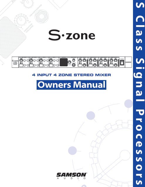
4 INPUT 4 ZONE STEREO MIXER<br />
S C l a s s S i g n a l P r o c e s s o r s
Safety Instructions/Consignes de sécurité/Sicherheitsvorkehrungen<br />
WARNING: To reduce the risk of fire or electric shock, do not expose this unit to rain or moisture. To reduce the hazard of electrical shock, do not remove cover or back. No<br />
user serviceable parts inside. Please refer all servicing to qualified personnel.The lightning flash with an arrowhead symbol within an equilateral triangle, is intended to alert<br />
the user to the presence of uninsulated "dangerous voltage" within the products enclosure that may be of sufficient magnitude to constitute a risk of electric shock to persons.<br />
The exclamation point within an equilateral triangle is intended to alert the user to the presence of important operating and maintenance (servicing) instructions in the<br />
literature accompanying the product.<br />
Important Safety Instructions<br />
1. Please read all instructions before operating the unit.<br />
2. Keep these instructions for future reference.<br />
3. Please heed all safety warnings.<br />
4. Follow manufacturers instructions.<br />
5. Do not use this unit near water or moisture.<br />
6. Clean only with a damp cloth.<br />
7. Do not block any of the ventilation openings. Install in accordance with the manufacturers instructions.<br />
8. Do not install near any heat sources such as radiators, heat registers, stoves, or other apparatus (including amplifiers) that produce heat.<br />
9. Do not defeat the safety purpose of the polarized or grounding-type plug. A polarized plug has two blades with one wider than the other. A grounding type plug has<br />
two blades and a third grounding prong. The wide blade or third prong is provided for your safety. When the provided plug does not fit your outlet, consult an electrician<br />
for replacement of the obsolete outlet.<br />
10. Protect the power cord from being walked on and pinched particularly at plugs, convenience receptacles and at the point at which they exit from the unit.<br />
11. Unplug this unit during lightning storms or when unused for long periods of time.<br />
12. Refer all servicing to qualified personnel. Servicing is required when the unit has been damaged in any way, such as power supply cord or plug damage, or if liquid has<br />
been spilled or objects have fallen into the unit, the unit has been exposed to rain or moisture, does not operate normally, or has been dropped.<br />
ATTENTION: Pour éviter tout risque d’électrocution ou d’incendie, ne pas exposer cet appareil à la pluie ou à l’humidité. Pour éviter tout risque d’électrocution, ne pas ôter le<br />
couvercle ou le dos du boîtier. Cet appareil ne contient aucune pièce remplaçable par l'utilisateur. Confiez toutes les réparations à un personnel qualifié. Le signe avec un éclair<br />
dans un triangle prévient l’utilisateur de la présence d’une tension dangereuse et non isolée dans l’appareil. Cette tension constitue un risque d’électrocution. Le signe avec<br />
un point d’exclamation dans un triangle prévient l’utilisateur d’instructions importantes relatives à l’utilisation et à la maintenance du produit.<br />
Consignes de sécurité importantes<br />
1. Veuillez lire toutes les instructions avant d’utiliser l’appareil.<br />
2. Conserver ces instructions pour toute lecture ultérieure.<br />
3. Lisez avec attention toutes les consignes de sécurité.<br />
4. Suivez les instructions du fabricant.<br />
5. Ne pas utiliser cet appareil près d’une source liquide ou dans un lieu humide.<br />
6. Nettoyez l’appareil uniquement avec un tissu humide.<br />
7. Veillez à ne pas obstruer les fentes prévues pour la ventilation de l’appareil. Installez l’appareil selon les instructions du fabricant.<br />
8. Ne pas installer près d’une source de chaleur (radiateurs, etc.) ou de tout équipement susceptible de générer de la chaleur (amplificateurs de puissance par exemple).<br />
9. Ne pas retirer la terre du cordon secteur ou de la prise murale. Les fiches canadiennes avec polarisation (avec une lame plus large) ne doivent pas être modifiées. Si votre<br />
prise murale ne correspond pas au modèle fourni, consultez votre électricien.<br />
10. Protégez le cordon secteur contre tous les dommages possibles (pincement, tension, torsion,, etc.). Veillez à ce que le cordon secteur soit libre, en particulier à sa sortie<br />
du boîtier.<br />
11. Déconnectez l’appareil du secteur en présence d’orage ou lors de périodes d’inutilisation prolongées.<br />
12. Consultez un service de réparation qualifié pour tout dysfonctionnement (dommage sur le cordon secteur, baisse de performances, exposition à la pluie, projection liquide<br />
dans l’appareil, introduction d’un objet dans le boîtier, etc.).<br />
ACHTUNG: Um die Gefahr eines Brandes oder Stromschlags zu verringern, sollten Sie dieses Gerät weder Regen noch Feuchtigkeit aussetzen.Um die Gefahr eines<br />
Stromschlags zu verringern, sollten Sie weder Deckel noch Rückwand des Geräts entfernen. Im Innern befinden sich keine Teile, die vom Anwender gewartet werden können.<br />
Überlassen Sie die Wartung qualifiziertem Fachpersonal.Der Blitz mit Pfeilspitze im gleichseitigen Dreieck soll den Anwender vor nichtisolierter “gefährlicher Spannung”<br />
im Geräteinnern warnen. Diese Spannung kann so hoch sein, dass die Gefahr eines Stromschlags besteht. Das Ausrufezeichen im gleichseitigen Dreieck soll den Anwender<br />
auf wichtige Bedienungs- und Wartungsanleitungen aufmerksam machen, die im mitgelieferten Informationsmaterial näher beschrieben werden.<br />
Wichtige Sicherheitsvorkehrungen<br />
1. Lesen Sie alle Anleitungen, bevor Sie das Gerät in Betrieb nehmen.<br />
2. Bewahren Sie diese Anleitungen für den späteren Gebrauch gut auf.<br />
3. Bitte treffen Sie alle beschriebenen Sicherheitsvorkehrungen.<br />
4. Befolgen Sie die Anleitungen des Herstellers.<br />
5. Benutzen Sie das Gerät nicht in der Nähe von Wasser oder Feuchtigkeit.<br />
6. Verwenden Sie zur Reinigung des Geräts nur ein feuchtes Tuch.<br />
7. Blockieren Sie keine Belüftungsöffnungen. Nehmen Sie den Einbau des Geräts nur entsprechend den Anweisungen des Herstellers vor.<br />
8. Bauen Sie das Gerät nicht in der Nähe von Wärmequellen wie Heizkörpern, Wärmeklappen, Öfen oder anderen Geräten (inklusive Verstärkern) ein, die Hitze erzeugen.<br />
9. Setzen Sie die Sicherheitsfunktion des polarisierten oder geerdeten Steckers nicht außer Kraft. Ein polarisierter Stecker hat zwei flache, unterschiedlich breite Pole. Ein<br />
geerdeter Stecker hat zwei flache Pole und einen dritten Erdungsstift. Der breitere Pol oder der dritte Stift dient Ihrer Sicherheit. Wenn der vorhandene Stecker nicht in<br />
Ihre Steckdose passt, lassen Sie die veraltete Steckdose von einem Elektriker ersetzen.<br />
10. Schützen Sie das Netzkabel dahingehend, dass niemand darüber laufen und es nicht geknickt werden kann. Achten Sie hierbei besonders auf Netzstecker,<br />
Mehrfachsteckdosen und den Kabelanschluss am Gerät.<br />
11. Ziehen Sie den Netzstecker des Geräts bei Gewittern oder längeren Betriebspausen aus der Steckdose.<br />
12. Überlassen Sie die Wartung qualifiziertem Fachpersonal. Eine Wartung ist notwendig, wenn das Gerät auf irgendeine Weise, beispielsweise am Kabel oder Netzstecker<br />
beschädigt wurde, oder wenn Flüssigkeiten oder Objekte in das Gerät gelangt sind, es Regen oder Feuchtigkeit ausgesetzt war, nicht mehr wie gewohnt betrieben<br />
werden kann oder fallen gelassen wurde.
Instrucciones de seguridad / Istruzioni di Sicurezza<br />
PRECAUCION: Para reducir el riesgo de incendios o descargas, no permita que este aparato quede expuesto a la lluvia o la humedad. Para reducir el riesgo de descarga<br />
eléctrica, nunca quite la tapa ni el chasis. Dentro del aparato no hay piezas susceptibles de ser reparadas por el usuario. Dirija cualquier reparación al servicio técnico oficial.<br />
El símbolo del relámpago dentro del triángulo equilátero pretende advertir al usuario de la presencia de “voltajes peligrosos” no aislados dentro de la carcasa del producto,<br />
que pueden ser de la magnitud suficiente como para constituir un riesgo de descarga eléctrica a las personas. El símbolo de exclamación dentro del triángulo equilátero<br />
quiere advertirle de la existencia de importantes instrucciones de manejo y mantenimiento (reparaciones) en los documentos que se adjuntan con este aparato.<br />
Instrucciones importantes de seguridad<br />
1. Lea todo este manual de instrucciones antes de comenzar a usar la unidad.<br />
2. Conserve estas instrucciones para cualquier consulta en el futuro.<br />
3. Cumpla con todo lo indicado en las precauciones de seguridad.<br />
4. Observe y siga todas las instrucciones del fabricante.<br />
5. Nunca utilice este aparato cerca del agua o en lugares húmedos.<br />
6. Limpie este aparato solo con un trapo suave y ligeramente humedecido.<br />
7. No bloquee ninguna de las aberturas de ventilación. Instale este aparato de acuerdo a las instrucciones del fabricante.<br />
8. No instale este aparato cerca de fuentes de calor como radiadores, calentadores, hornos u otros aparatos (incluyendo amplificadores) que produzcan calor.<br />
9. No anule el sistema de seguridad del enchufe de tipo polarizado o con toma de tierra. Un enchufe polarizado tiene dos bornes, uno más ancho que el otro. Uno con<br />
toma de tierra tiene dos bornes normales y un tercero para la conexión a tierra. El borne ancho o el tercero se incluyen como medida de seguridad. Cuando el enchufe<br />
no encaje en su salida de corriente, llame a un electricista para que le cambie su salida anticuada.<br />
10. Evite que el cable de corriente quede en una posición en la que pueda ser pisado o aplastado, especialmente en los enchufes, receptáculos y en el punto en el que<br />
salen de la unidad.<br />
11. Desconecte de la corriente este aparato durante las tormentas eléctricas o cuando no lo vaya a usar durante un periodo de tiempo largo.<br />
12. Dirija cualquier posible reparación solo al servicio técnico oficial. Deberá hacer que su aparato sea reparado cuando esté dañado de alguna forma, como si el cable de<br />
corriente o el enchufe están dañados, o si se han derramado líquidos o se ha introducido algún objeto dentro de la unidad, si esta ha quedado expuesta a la lluvia o la<br />
humedad, si no funciona normalmente o si ha caído al suelo.<br />
ATTENZIONE: per ridurre il rischio di incendio o di scariche elettriche, non esponete questo apparecchio a pioggia o umidità. Per ridurre il pericolo di scariche elettriche evitate<br />
di rimuoverne il coperchio o il pannello posteriore. Non esistono all'interno dell'apparecchio parti la cui regolazione è a cura dell'utente. Per eventuale assistenza, fate riferimento<br />
esclusivamente a personale qualificato. Il fulmine con la punta a freccia all'interno di un triangolo equilatero avvisa l'utente della presenza di "tensioni pericolose" non isolate<br />
all'interno dell'apparecchio, tali da costituire un possibile rischio di scariche elettriche dannose per le persone. Il punto esclamativo all'interno di un triangolo equilatero avvisa<br />
l'utente della presenza di importanti istruzioni di manutenzione (assistenza) nella documentazione che accompagna il prodotto.<br />
Importanti Istruzioni di Sicurezza<br />
1. Prima di usare l'apparecchio, vi preghiamo di leggerne per intero le istruzioni.<br />
2. Conservate tali istruzioni per una eventuale consultazione futura.<br />
3. Vi preghiamo di rispettare tutte le istruzioni di sicurezza.<br />
4. Seguite tutte le istruzioni del costruttore.<br />
5. Non usate questo apparecchio vicino ad acqua o umidità.<br />
6. Pulite l'apparecchio esclusivamente con un panno asciutto.<br />
7. Evitate di ostruire una qualsiasi delle aperture di ventilazione. Posizionatelo seguendo le istruzioni del costruttore.<br />
8. Non posizionatelo vicino a sorgenti di calore come radiatori, scambiatori di calore, forni o altri apparecchi (amplificatori compresi) in grado di generare calore.<br />
9. Non disattivate la protezione di sicurezza costituita dalla spina polarizzata o dotata di collegamento a terra. Una spina polarizzata è dotata di due spinotti, uno più<br />
piccolo ed uno più grande. Una spina dotata di collegamento a terra è dotata di due spinotti più un terzo spinotto di collegamento a terra. Questo terzo spinotto, eventualmente<br />
anche più grande, viene fornito per la vostra sicurezza. Se la spina fornita in dotazione non si adatta alla vostra presa, consultate un elettricista per la sostituzione<br />
della presa obsoleta.<br />
10. Proteggete il cavo di alimentazione in modo che non sia possibile camminarci sopra né piegarlo, con particolare attenzione alle prese, ai punti di collegamento e al punto<br />
in cui esce dall'apparecchio.<br />
11. Staccate l'apparecchio dalla alimentazione in caso di temporali o tempeste o se non lo usate per un lungo periodo.<br />
12. Per l'assistenza, fate riferimento esclusivamente a personale qualificato. È necessaria l'assistenza se l'apparecchio ha subito un qualsiasi tipo di danno, come danni al cavo<br />
o alla spina di alimentazione, nel caso in cui sia stato versato del liquido o siano caduti oggetti al suo interno, sia stato esposto a pioggia o umidità, non funzioni corret-<br />
tamente o sia stato fatto cadere.
Copyright 2004 - 2006, <strong>Samson</strong> Technologies Corp.<br />
Version 5.0 Printed October, 2006<br />
<strong>Samson</strong> Technologies Corp.<br />
45 Gilpin Avenue<br />
Hauppauge, New York 11788-8816<br />
Phone: 1-800-3-SAMSON (1-800-372-6766)<br />
Fax: 631-784-2201<br />
www.samsontech.com
ENGLISH<br />
Introduction .........................................................................................................................2<br />
S <strong>zone</strong> Features ...................................................................................................................3<br />
Controls and Functions ....................................................................................................4<br />
Front Panel Layout .............................................................................................................4<br />
Controls and Functions ....................................................................................................5<br />
Rear Panel Layout ...............................................................................................................5<br />
Designing an Installation Plan .......................................................................................6<br />
Setting up the S <strong>zone</strong> ........................................................................................................8<br />
Quick Start ............................................................................................................................8<br />
Connecting the S <strong>zone</strong> .....................................................................................................10<br />
Connecting the S <strong>zone</strong> Inputs .......................................................................................10<br />
Connecting the S <strong>zone</strong> Zone Outputs ........................................................................11<br />
Connecting the S Zone Outputs - continued. ..........................................................11<br />
Connecting a Remote Level Control on a Zone Output .....................................11<br />
Operating the S <strong>zone</strong> ........................................................................................................12<br />
Using the S <strong>zone</strong> Input Section .....................................................................................12<br />
Using the Monitor Section ..............................................................................................13<br />
Controlling the Zone Outputs .......................................................................................14<br />
Using a Remote Level Control on a Zone Output ..................................................14<br />
Using the Equalizer ............................................................................................................15<br />
Using the Ducker ................................................................................................................16<br />
S <strong>zone</strong> System Configurations .......................................................................................18<br />
Using the S <strong>zone</strong> with Active Speakers ......................................................................18<br />
Using the S <strong>zone</strong> with Passive Speakers .....................................................................18<br />
S <strong>zone</strong>’s Four Room Set-up ............................................................................................19<br />
S <strong>zone</strong> Wiring Guide ..........................................................................................................20<br />
S <strong>zone</strong> Specifications.........................................................................................................97<br />
S <strong>zone</strong> Block Diagram .......................................................................................................102<br />
FRANÇAIS<br />
Introduction .........................................................................................................................21<br />
S <strong>zone</strong> - Caractéristiques..................................................................................................22<br />
Commandes et fonctions ................................................................................................23<br />
Face avant .............................................................................................................................23<br />
Commandes et fonctions ................................................................................................24<br />
Face arrière ...........................................................................................................................24<br />
Élaboration d’un plan d’installation ............................................................................25<br />
Configuration du S <strong>zone</strong> ..................................................................................................27<br />
Prise en main ........................................................................................................................27<br />
Connexion du S <strong>zone</strong> ........................................................................................................29<br />
Connexion aux entrées du S <strong>zone</strong> ................................................................................29<br />
Connexion aux sorties Zone du S <strong>zone</strong> ......................................................................30<br />
Connexion aux sorties Zone du S <strong>zone</strong> - suite .........................................................30<br />
Connexion d’un réglage de volume à distance à une sortie Zone ...................30<br />
Utilisation du S <strong>zone</strong>..........................................................................................................31<br />
Utilisation de la section d’entrée du S <strong>zone</strong> ..............................................................31<br />
Utilisation de la section Monitor ...................................................................................32<br />
Utilisation des sorties Zone ............................................................................................33<br />
Connexion d’un réglage de volume à distance à une sortie Zone ...................33<br />
Utilisation de l’égaliseur ...................................................................................................34<br />
Atténuation automatique ...............................................................................................35<br />
Schémas d’installation ......................................................................................................37<br />
Utilisation du S <strong>zone</strong> avec des enceintes actives ....................................................37<br />
Utilisation du S <strong>zone</strong> avec des enceintes passives .................................................37<br />
Utilisation du S <strong>zone</strong> pour la diffusion dans quatre pièces .................................38<br />
Connexion des entrées du S <strong>zone</strong> ................................................................................39<br />
S <strong>zone</strong> - Caractéristiques techniques ..........................................................................98<br />
Synoptique ...........................................................................................................................102<br />
DEUTSCHE<br />
Einleitung ..............................................................................................................................40<br />
S <strong>zone</strong> Features ...................................................................................................................41<br />
Regler und Funktionen .....................................................................................................42<br />
Layout der Vorderseite .....................................................................................................42<br />
Regler und Funktionen .....................................................................................................43<br />
Layout der Rückseite .........................................................................................................43<br />
Installationsplan entwickeln ..........................................................................................44<br />
S <strong>zone</strong> einrichten ................................................................................................................46<br />
Schnellstart ...........................................................................................................................46<br />
S <strong>zone</strong> anschließen ............................................................................................................48<br />
S <strong>zone</strong>-Eingänge verbinden ...........................................................................................48<br />
S <strong>zone</strong> Zone-Ausgänge anschließen ...........................................................................49<br />
S Zone-Ausgänge anschließen - Fortsetzung. .........................................................49<br />
Pegel-Fernbedienung an Zone-Ausgang anschließen .........................................49<br />
S <strong>zone</strong> bedienen .................................................................................................................50<br />
S <strong>zone</strong> Eingangssektion einsetzen ...............................................................................50<br />
Monitor-Sektion verwenden ..........................................................................................51<br />
Zone-Ausgänge steuern ..................................................................................................52<br />
Pegel-Fernbedienung für Zone-Ausgang einsetzen .............................................52<br />
Equalizer verwenden ........................................................................................................53<br />
Ducker einsetzen ................................................................................................................54<br />
S <strong>zone</strong> Systemkonfigurationen .....................................................................................56<br />
S <strong>zone</strong> mit Aktivboxen betreiben .................................................................................56<br />
S <strong>zone</strong> mit Passivboxen betreiben ...............................................................................56<br />
4-Raum-Setup des S <strong>zone</strong> ..............................................................................................57<br />
S <strong>zone</strong> Verdrahtungsanleitung ......................................................................................58<br />
S <strong>zone</strong> Technische Daten .................................................................................................99<br />
Blockdiagramm ...................................................................................................................102<br />
ESPAÑOL<br />
Introducción .........................................................................................................................59<br />
Características del S <strong>zone</strong> ................................................................................................60<br />
Controles y funciones .......................................................................................................61<br />
Distribución del panel frontal ........................................................................................61<br />
Controles y funciones .......................................................................................................62<br />
Distribución del panel trasero .......................................................................................62<br />
Arranque rápido .................................................................................................................65<br />
Conexión de las entradas del S <strong>zone</strong> ...........................................................................67<br />
Conexión de las salidas del S Zone ..............................................................................68<br />
Conexión de las salidas del S Zone - continuación. ...............................................68<br />
Conexión de un control remoto de nivel en una salida de zona ......................68<br />
Uso de la sección de entrada del S <strong>zone</strong> ....................................................................69<br />
Uso de la sección Monitor ...............................................................................................70<br />
Control de las zonas de salida ........................................................................................71<br />
Uso de un control remoto de volumen en una zona de salida ..........................71<br />
Uso del ecualizador ...........................................................................................................72<br />
Uso del Ducker ....................................................................................................................73<br />
Uso del S <strong>zone</strong> con altavoces activos ..........................................................................75<br />
Uso del S <strong>zone</strong> con altavoces pasivos .........................................................................75<br />
Configuración de cuatro salas con el S <strong>zone</strong> ............................................................76<br />
Guía del cableado del S <strong>zone</strong> .........................................................................................77<br />
Especificaciones técnicas del S <strong>zone</strong> ...........................................................................100<br />
Diagrama de bloques........................................................................................................102<br />
ITALIANO<br />
Introduzione .........................................................................................................................78<br />
S <strong>zone</strong> - le Caratteristiche ................................................................................................79<br />
Controlli e Funzioni ............................................................................................................80<br />
Il Pannello Frontale ............................................................................................................80<br />
Controlli e Funzioni ............................................................................................................81<br />
Il Pannello Posteriore ........................................................................................................81<br />
La Progettazione del Piano di Installazione ..............................................................82<br />
La Progettazione del Piano di Installazione ..............................................................83<br />
La Messa in Opera dell'S <strong>zone</strong> ........................................................................................84<br />
Uso Immediato ....................................................................................................................84<br />
La Messa in Opera dell'S <strong>zone</strong> ........................................................................................85<br />
Il Collegamento dell'S <strong>zone</strong> ............................................................................................86<br />
Il Collegamento degli Ingressi dell'S <strong>zone</strong>.................................................................86<br />
Il Collegamento dell'S <strong>zone</strong> ............................................................................................87<br />
Il Collegamento delle Uscite di Zona dell'S Zone - ................................................87<br />
continua. ................................................................................................................................87<br />
Il Collegamento di un Controllo di Livello Remoto a una Uscita di Zona .....87<br />
L'Uso dell'S <strong>zone</strong> ..................................................................................................................88<br />
L'Uso della Sezione di Ingresso dell'S <strong>zone</strong> ...............................................................88<br />
L'Uso dell'S <strong>zone</strong> ..................................................................................................................89<br />
L'Uso della Sezione Monitor ...........................................................................................89<br />
L'Uso dell'S <strong>zone</strong> ..................................................................................................................90<br />
La Regolazione delle Uscite di Zona ............................................................................90<br />
L'Uso di un Controllo di Livello Remoto su di una Uscita di Zona .....................90<br />
L'Uso dell'S <strong>zone</strong> ..................................................................................................................91<br />
L'Uso dell'Equalizzatore ....................................................................................................91<br />
L'Uso dell'S <strong>zone</strong> ..................................................................................................................92<br />
L'Uso del Ducker (Attenuatore Automatico) .............................................................92<br />
L'Uso dell'S <strong>zone</strong> ..................................................................................................................93<br />
S <strong>zone</strong> - Configurazioni di Sistema ...............................................................................94<br />
L'Uso dell'S <strong>zone</strong> con Casse Acustiche Attive ...........................................................94<br />
L'Uso dell'S <strong>zone</strong> con Casse Acustiche Passive .........................................................94<br />
S <strong>zone</strong> - Configurazioni di Sistema ...............................................................................95<br />
Configurazione dell'S <strong>zone</strong> per la gestione di 4 ambienti ..................................95<br />
S <strong>zone</strong> - Guida al Cablaggio ............................................................................................96<br />
S <strong>zone</strong> - Specifiche .............................................................................................................101<br />
Diagramma a Blocchi .......................................................................................................102
ENGLISH<br />
Introduction<br />
Congratulations on purchasing the <strong>Samson</strong> S <strong>zone</strong>, four<br />
channel, stereo <strong>zone</strong> mixer! Although this product is<br />
designed for easy operation, we suggest you take some<br />
time out first to go through these pages so you can fully<br />
understand how we’ve implemented a number of unique<br />
features.<br />
The S <strong>zone</strong> is a professional quality 4-channel <strong>zone</strong> mixer<br />
that allows you to mix just about any audio signal including<br />
those from microphones, stereo CD and tape players,<br />
video players, and then lets you distribute an independent<br />
mix to any of the four stereo <strong>zone</strong>s. Each of the<br />
input channels is assignable to any or all of 4 stereo <strong>zone</strong>s<br />
outputs via easy to use LED backlit switches. The microphone<br />
inputs can be set to “duck” the <strong>zone</strong> inputs so that<br />
the background music automatically turns down when<br />
an announcement is made. On each the S <strong>zone</strong>’s outputs,<br />
you’ll find a convenient two-band equalizer allowing you<br />
to adjust the overall tonal response of each <strong>zone</strong>. A fivesegment<br />
LED bar VU meter is present on all outputs providing<br />
a visual display of the level of each <strong>zone</strong>. Perhaps<br />
the most unique feature of the S <strong>zone</strong> is it's front panel<br />
monitor section. The <strong>zone</strong> assignment switch, headphone<br />
jack, level control and internal super speaker allow you to<br />
monitor the signal that is playing in any <strong>zone</strong> directly on<br />
the S <strong>zone</strong>, without having to physically be in the room<br />
that signal is playing in. The handy scribe strip for both<br />
the inputs and outputs make it easy to label the connected<br />
gear and the rooms the S <strong>zone</strong> is feeding. For easy<br />
installation, all the S <strong>zone</strong> connections are made with<br />
standard Euroblock connection strips.<br />
In this manual, you’ll find a detailed description of the<br />
features of the S <strong>zone</strong>, as well as a guided tour through<br />
the front and rear panels, step-by-step instructions for<br />
using the unit, suggested applications and full specifications.<br />
You’ll also find a warranty card enclosed—please don’t<br />
forget to fill it out and mail it so that you can receive<br />
online technical support and so we can send you<br />
updated information about other <strong>Samson</strong> products in<br />
the future. Also, be sure to check out our website (www.<br />
samsontech.com) for complete information about our full<br />
product line.<br />
2<br />
With proper care and adequate air circulation, your S<br />
<strong>zone</strong> will operate trouble free for many years. We recommend<br />
you record your serial number in the space provided<br />
below for future reference.<br />
Serial number: _______________________________<br />
Date of purchase: _____________________________<br />
Should your unit ever require servicing, a Return<br />
Authorization number (RA) must be obtained before<br />
shipping your unit to <strong>Samson</strong>. Without this number, the<br />
unit will not be accepted. Please call <strong>Samson</strong> at 1-800-<br />
3SAMSON (1-800-372-6766) for a Return Authorization<br />
number prior to shipping your unit. Please retain the<br />
original packing materials and if possible, return the unit<br />
in the original carton and packing materials.
• The S <strong>zone</strong> has four stereo Input Channels with a<br />
Volume control, Stereo/Mono switch and our dedicated<br />
Zone assignment switches.<br />
• Channel 1 and Channel 2 inputs feature a high<br />
quality microphone pre-amp with phantom power<br />
allowing you to connect just about any dynamic or<br />
condenser microphone.<br />
• The S <strong>zone</strong> features four stereo Zone Outputs, each<br />
with a Stereo/Mono switch, Volume control, High<br />
and Low equalizers and a six-segment LED bar VU<br />
Meter monitoring the output level, enabling you to<br />
control the overall level and tone independently for<br />
four discreet coverage areas.<br />
• A remote Volume Control for each Zone Output, up<br />
to 3000 feet in distance is possible using standard<br />
50k –100k linear taper potentiometer and two-conductor<br />
shielded wire.<br />
• Microphone “Duck” switch on Channel 1 and<br />
Channel 2, which when turned on, allow any signal<br />
from the microphone inputs, like an announcement<br />
or page, to automatically lower the background<br />
music level.<br />
• The S <strong>zone</strong> features a unique front panel monitor<br />
section including a <strong>zone</strong> assignment switch, headphone<br />
jack, level control and internal super speaker<br />
allowing you to monitor the signal that is playing in<br />
any <strong>zone</strong> directly on the S <strong>zone</strong>, without having to<br />
physically be in the room that the signal is playing in.<br />
S <strong>zone</strong> Features<br />
The <strong>Samson</strong> S <strong>zone</strong> four-channel stereo <strong>zone</strong> mixer utilizes state-of-the-art, high quality audio circuit technology<br />
for precise tonal and level control. Here are some of the S <strong>zone</strong>’s main features:<br />
3<br />
• Ultra-low noise circuitry with high quality op-amps<br />
ensure superb audio fidelity.<br />
• Electronically balanced and unbalanced input<br />
and output connections are made via easy to use<br />
Euroblock connection strips.<br />
• Internal power supply ensures reliability and troublefree<br />
operation.<br />
• Standard 19" rack design (the S <strong>zone</strong> requires only a<br />
single rack space) for easy integration into any traveling<br />
or fixed installation audio system.<br />
• Optional security cover kit prevents S Zone settings<br />
from accidentally being altered.<br />
• All-steel chassis makes the S <strong>zone</strong> eminently roadworthy.<br />
• Three year extended warranty.<br />
ENGLISH
ENGLISH<br />
Controls and Functions<br />
Front Panel Layout<br />
<br />
<br />
INPUT SECTION<br />
1 VOLUME – Rotary control used to adjust the level of<br />
signal source connected to channel 1.<br />
2 ZONE 1 – When the LED Backlit switch is pressed<br />
in, the switch lights red and the input is assigned to<br />
ZONE 1.<br />
3 ZONE 2 – When the LED Backlit switch is pressed in,<br />
the switch lights green and the input is assigned to<br />
ZONE 2.<br />
4 STEREO/MONO switch - This switch is used to<br />
select either stereo or mono input.<br />
5 SCRIBE STRIP – Convenient area for marking the<br />
input source allowing you to label the channel with<br />
the device connected to the input.<br />
6 ZONE 3 – When the LED Backlit switch is pressed in,<br />
the switch lights amber and the input is assigned to<br />
ZONE 3.<br />
7 ZONE 4 – When the LED Backlit switch is pressed in,<br />
the switch lights orange and the input is assigned to<br />
ZONE 4.<br />
8 MIC/LINE 2 – Channel 2 input with the same knob<br />
and switch complement as Channel 1.<br />
9 LINE 3 – Channel 3 input with the same knob and<br />
switch complement as Channel 1.<br />
10 LINE 4 – Channel 4 input with the same knob and<br />
switch complement as Channel 1.<br />
MONITOR SECTION<br />
11 MONITOR SPEAKER – This built-in, miniature superspeaker<br />
allows you to listen to the signal that is present<br />
at any ZONE OUTPUT.<br />
12 MONITOR VOLUME - This rotary control is used<br />
to adjust the monitor level heard in the front panel<br />
Headphone jack or SUPER SPEAKER.<br />
<br />
4<br />
<br />
<br />
13 ZONE SELECT switch – This four-position switch is<br />
used to assign any of the four Zones to play in the<br />
MONITOR SPEAKER or HEADPHONE JACK.<br />
14 HEADPHONE JACK - Connect any standard stereo<br />
headphone using a standard 1/4-inch jack to monitor<br />
the ZONE OUTPUTS.<br />
ZONE OUTPUT SECTION<br />
15 VOLUME – This rotary control is used to control the<br />
overall level of OUTPUT ZONE 1.<br />
16 HIGH – High frequency equalizer rotary control<br />
with +/-12 dB of cut or boost at 10kHz.<br />
17 OUTPUT METER – Six-segment LED meter displaying<br />
the level of the ZONE 1 OUTPUT with -20 to +14<br />
dB indicators.<br />
18 STEREO/MONO switch - This switch is used to<br />
select either stereo or mono operation on the ZONE<br />
1 OUTPUT.<br />
19 SCRIBE STRIP – Convenient area for marking the<br />
ZONE OUTPUT allowing you to notate the room or<br />
area the <strong>zone</strong> is feeding.<br />
20 LOW– Low frequency equalizer rotary control with<br />
+/-12 dB of cut or boost at 100Hz.<br />
21 ZONE OUTPUT 2 – ZONE 2 OUTPUT with the same<br />
knob and switch complement as ZONE 1 OUTPUT.<br />
22 ZONE OUTPUT 3 – ZONE 3 OUTPUT with the same<br />
knob and switch complement as ZONE 1 OUTPUT.<br />
23 ZONE OUTPUT 4 – ZONE 4 OUTPUT with the same<br />
knob and switch complement as ZONE 1 OUTPUT.<br />
24 POWER switch – Use this switch to power the unit<br />
on and off.
Rear Panel Layout<br />
A AC INPUT FUSE HOLDER – Connect the supplied 3pin<br />
IEC power cable here.<br />
B ZONE 1 OUTPUT – This connector includes the Zone<br />
1 Left and Right balanced output connections, along<br />
with the connections for the REMOTE volume control.<br />
C ZONE 2 OUTPUT – This connector includes the Zone<br />
2 Left and Right balanced output connections, along<br />
with the connections for the REMOTE volume control.<br />
D ZONE 3 OUTPUT – This connector includes the Zone<br />
3 Left and Right balanced output connections, along<br />
with the connections for the REMOTE volume control.<br />
E ZONE 4 OUTPUT – This connector includes the Zone<br />
4 Left and Right balanced output connections, along<br />
with the connections for the REMOTE volume control.<br />
F LINE 3 AND 4 INPUT - This connector is used to<br />
hook up the LINE 3 and 4 Left and Right input connections.<br />
G DUCK TRIM – This rotary control is used to adjust<br />
how much signal level is dropped when the microphone<br />
activates the DUCK circuit.<br />
H MIC/LINE 2 – This connector includes the connection<br />
for a stereo line level and mono microphone<br />
input for channel 2.<br />
5<br />
Controls and Functions<br />
I MIC TRIM – The rotary control is used to adjust<br />
the input sensitivity of the microphone pre<br />
amplifier on channel 2.<br />
J MIC/LINE 1 – This connector includes the connection<br />
for a stereo line level and mono microphone<br />
input for channel 1.<br />
K MIC TRIM – The rotary control is used to adjust<br />
the input sensitivity of the microphone pre<br />
amplifier on channel 2.<br />
L CH 1 MASTER switch – This switch is used to<br />
enable the ducking function on channels 2, 3<br />
and 4.<br />
M DUCK ENABLE– Channel 2 will act as a ducking<br />
master when this switch is pressed in and the<br />
volume of channels 3 and 4 will automatically<br />
be lowered when the there is a microphone<br />
signal on Channel 2.<br />
N DUCK ENABLE – Channel 1 will act as a ducking<br />
master when this switch is pressed in and<br />
the volume of channels 3 and 4 will automatically<br />
be lowered when the there is a microphone<br />
signal on Channel 1.<br />
ENGLISH
ENGLISH<br />
Designing an Installation Plan<br />
Designing an Installation Plan<br />
If you are a professional installer, you’ll probably want to<br />
skip over this section, however if you are setting up your<br />
system for the first time this section can help make your<br />
installation a little bit easier.<br />
Before you start plugging, stripping and connecting wires,<br />
it a good idea to have a clear installation plan. To create<br />
your installation plan you need to consider several design<br />
parameters including what sound sources will be used, if<br />
announcement paging in necessary, which rooms need<br />
to have sound, is remote volume control required, which<br />
type of speakers will do the best job for the room they are<br />
covering, and your wire plan.<br />
Selecting the Sound Sources<br />
The S <strong>zone</strong> provides four input channels with the ability<br />
to connect up to six input sources. On input Channel’s 1<br />
and 2 there is an input for connecting microphones with<br />
phantom power to operate condenser type mics. You can<br />
connect line level signals on all four input channels, so signals<br />
from TAPE, CD, DVD or Karaoke players, Audio Video<br />
TV monitors, Radio Tuners, DJ mixers or any other line level<br />
device can be used as a sound source. You may also be<br />
able to connect the output from a Home Hi-fi receiver if it’s<br />
equipped with a line level output. For example, in a small<br />
to medium size restaurant you may want background<br />
music from a CD in a room, Disco Karaoke in another room<br />
and have the ability to have a hostess paging parties for<br />
their tables, and a cook paging a waitress to pick up an<br />
order. The S <strong>zone</strong> can accomplish all of this easily.<br />
Creating the Audio Zones<br />
You can create separate audio environments using the S<br />
<strong>zone</strong>’s four output channels. Obviously, (or not perhaps<br />
not so obviously,) we call an output a <strong>zone</strong> on the unit, but<br />
a <strong>zone</strong> is also the area where you want to have sound. So,<br />
think about where you want to distribute the sound. The<br />
S <strong>zone</strong> can accomplish all of this easily. In addition, the<br />
S <strong>zone</strong> let’s you easily connect a remote control level for<br />
each of the <strong>zone</strong>s, so you can control the volume in the<br />
room even if the audio equipment is located somewhere<br />
else.<br />
6<br />
Now, take some time to consider where you need to<br />
have sound in your particular installation. After you have<br />
decided where you need to create sound <strong>zone</strong>s, you can<br />
consider your speaker selection, but first decide where you<br />
are going to locate your equipment rack.<br />
Locating Your Equipment Rack<br />
Since the S <strong>zone</strong> is standard19-inch rack mount device,<br />
you should consider using an equipment rack, such as the<br />
<strong>Samson</strong> SRK8. To select a good location for your equipment<br />
rack you should consider several points including<br />
the proximity to each of the sound <strong>zone</strong>s, if the users<br />
need to access the gear like to change CD’s or to adjust a<br />
volume level and if you have a convenient location to the<br />
electrical service, to name a few. You will need to consider<br />
the length of wire runs and routing necessary to make the<br />
connections from the equipment rack to the various sound<br />
<strong>zone</strong>s. Depending on the speakers you choose, and the<br />
length of cable runs you need to make, you may choose<br />
to run speaker level or line level to the sound <strong>zone</strong>s. If you<br />
are using passive (non-powered) speakers you will need to<br />
connect the S <strong>zone</strong> to a power amp and run speaker wire,<br />
however you need to be careful to pay attention to the<br />
wire gauge and total length of the wire run. If you are using<br />
powered (active) speakers you can run long distances<br />
using the balanced outputs directly from the S <strong>zone</strong>.<br />
Another type of installation is one that uses speakers<br />
and amplifiers with 70-volt transformers. The benefit of<br />
these systems you can run long lengths of wire and have<br />
many speakers connected to a single amplifier. Since the<br />
equipment used in these types of installations are fairly<br />
specialized, you’ll probably need professional help. Only a<br />
licensed and insured professional sound contractor should<br />
perform installations of 70-volt systems.<br />
Selecting Speakers for Each Zone<br />
To select the speakers you need to consider a few important<br />
issues like where you are going to place your power<br />
amplifiers, using powered or un-powered speakers, or if<br />
you need to run a 70-volt distributed sound system. The<br />
following sections provide an overview on how to connect<br />
passive speaker or active speakers in a typical installation.
Using Passive Speakers<br />
If you are using passive (un-powered) speakers you need<br />
to first decide where you will place your power amplifier.<br />
If the speakers in a particular sound <strong>zone</strong> are less than 100<br />
feet away you can locate your power amplifier in the same<br />
rack as the S <strong>zone</strong> and wire the speaker wires from the<br />
amplifier to your sound <strong>zone</strong>.<br />
NOTE: This type of wiring is known as "home-run wiring" since<br />
you are making direct connection from the amplifiers in the<br />
equipment rack to the speakers loicated in the sound <strong>zone</strong><br />
room.<br />
In this case, you would connect the S <strong>zone</strong>’s Zone Output<br />
to the power amplifier input and the run the speaker wires<br />
to the passive speakers. If the speakers in a particular<br />
sound <strong>zone</strong> are further than 100 feet, you should consider<br />
placing the amplifier in the same room as the sound <strong>zone</strong>.<br />
In this case you will run balanced line level signal from the<br />
S <strong>zone</strong>’s Zone Output over the long wire run to the input of<br />
the power amplifier located in the sound <strong>zone</strong>.<br />
Using Active Speakers<br />
If you are going more than 100 feet you can also consider<br />
using active speakers (speakers with built in power). When<br />
using active speakers you can connect the S <strong>zone</strong>’s outputs<br />
using the balanced line level signals. In this case you will<br />
run line level signal from the S <strong>zone</strong>’s Zone Output over<br />
the long wire run to the input of the powered speaker<br />
located in the sound <strong>zone</strong>. For more information on wiring<br />
for balanced signals see the wire guide on page 20 of this<br />
manual.<br />
Designing an Installation Plan<br />
7<br />
ENGLISH
ENGLISH<br />
Setting up the S <strong>zone</strong><br />
Quick Start<br />
We recommend that you take the time to read through<br />
this manual, and then, use it as a reference guide. If you are<br />
installing your first system you should read through the<br />
section “Designing an Installation Plan” on page 6 before<br />
you start connecting your S <strong>zone</strong>. If you’re a professional<br />
installer you can skip over that section and if you want to<br />
get started running some signals through your inputs and<br />
outputs, you can follow the following quick start example.<br />
Setting up your S <strong>zone</strong> is a simple procedure, which takes<br />
only a few minutes. The following section describes the<br />
set-up and operation of a simple installation using the S<br />
<strong>zone</strong> with a CD player and paging microphone.<br />
In this set up example, a paging microphone connected to<br />
the S <strong>zone</strong>’s CHANNEL 1 input and a CD player connected to<br />
CHANNEL 3. The S <strong>zone</strong>’s ZONE OUTPUT 1 is connected to a<br />
pair of active (self powered) speakers. If you are using passive<br />
speakers, the S <strong>zone</strong>’s ZONE OUTPUT should be connected to<br />
the power amp input.<br />
• Remove all packing materials (save them in case of<br />
need for future service) and decide where the unit is<br />
to be physically placed—it can be used freestanding<br />
or mounted in a standard 19” rack (The S <strong>zone</strong> requires<br />
only a single rack space).<br />
• Make sure the power to all input sources (like CD, DVD,<br />
MP3 & TAPE players) and amplifiers in your audio system<br />
is off.<br />
• Turn the volume control of your active speakers all the<br />
way off. If you are using passive speakers with a separate<br />
power amplifier, be sure to turn the power amp<br />
volume controls all the way off.<br />
8<br />
• On the front panel of the S <strong>zone</strong>, set all the VOLUME<br />
control knobs to their bottom-most “OFF” setting.<br />
• Set all ZONE OUTPUT LOW and HIGH Equalizer control<br />
Knobs to their flat (“0”) center detented position.<br />
• Now, make the S <strong>zone</strong> input connections, using the<br />
Euroblock connectors on the rear panel.<br />
• Next, make the S <strong>zone</strong> output connections, using the<br />
Euroblock connectors on the rear panel.<br />
• Plug in the supplied AC connector and connect it to<br />
any standard AC socket.<br />
• Press the front panel Power switch in order to turn on<br />
the S <strong>zone</strong>.<br />
• Power on your CD player, then power your active<br />
speaker or power amp.<br />
• On the Line 3 input channel, press the Zone 1 Switch.<br />
• Apply an input signal from the CD player to the S <strong>zone</strong><br />
and slowly raise the front panel LINE 3 Volume control<br />
knob to the “0” point.<br />
• While the input signal is present, slowly raise the front<br />
panel ZONE OUTPUT 1 control knob to the “0” point (if<br />
sending signal from a CD Player, drive the mixer’s output<br />
meters at approximately 0 VU).
Quick Start - continued<br />
• Once you get a good level reading on the ZONE<br />
OUTPUT VU meter, you can begin to slowly raise the<br />
volume control on your active speakers or power amp.<br />
Now experiment with the level using both the Zone 1 Output<br />
and the power amp input level. On active speakers, there is<br />
usually a unity gain or 0 dB point on the volume control knob<br />
and you should set the control to that position to start. Then,<br />
you may need to lower the ZONE OUTPUT VOLUME control, or<br />
the speaker's volume control to set the proper level that you<br />
want in your particular room. If your are using a power amp,<br />
you may want to turn the power amp all the way up, and<br />
again, you may need to lower the ZONE OUTPUT VOLUME<br />
control to set the proper level. You may also need to lower the<br />
ZONE OUTPUT VOLUME control, or the power amp's volume<br />
control to set the proper level that you want in your particular<br />
room. This concept is known as "gain staging" and it is the<br />
most important part of getting a good sound. Ideally, you<br />
want the S <strong>zone</strong>s Output level meter to read about O dB. This<br />
will give you the best signal to noise performance and cleanest<br />
sound. So, try to adjust the Zone Output Volume controls<br />
so that the VU Meter reads about 0 dB. Then adjust the volume<br />
control on the amplifier or speaker to a the desired listening<br />
level.<br />
• Now that you have the basic system operation level<br />
set, you can get a level setting for your microphone<br />
connected to the S <strong>zone</strong>’s CHANNEL 1 input. While<br />
speaking into your microphone, slowly raise the<br />
VOLUME control knob on CHANNEL 1 to the 0 position.<br />
• At this point if the microphone is very low in volume,<br />
raise the level of the rear panel MIC TRIM control. If the<br />
microphone is very high in volume, lower the level of<br />
the rear panel MIC TRIM control. You want to set the<br />
MIC TRIM so that you have a good range of level control<br />
on the CHANNEL 1 VOLUME control without adding<br />
any distortion.<br />
9<br />
Setting up the S <strong>zone</strong><br />
Note: The MIC TRIM level control allows you to set the best signal<br />
to noise level. Very simply put, this means the hottest mic<br />
level with the least amount of distortion. If the MIC TRIM is too<br />
low, the mic level may not be loud enough. If the MIC TRIM is<br />
set too high, the channel will distort. Use your ears to set the<br />
MIC TRIM to the highest point before you hear any distortion.<br />
Mic Trim<br />
• Experiment by moving each of the CHANNEL VOLUME<br />
control knobs up and down, carefully listening to get<br />
the best balance between your microphone and music<br />
from your CD player.<br />
Now, read on and learn about more different wiring hookups<br />
and more on using some of the S <strong>zone</strong>s advance features.<br />
If you have followed all the steps above and are experiencing<br />
difficulties with any aspect of setting up or using your<br />
S <strong>zone</strong>, you can call <strong>Samson</strong> Technical Support (1-800-372-<br />
6766) between 9 AM and 5 PM EST, or contact your local<br />
distributor.<br />
ENGLISH
ENGLISH<br />
Connecting the S <strong>zone</strong><br />
Get Connected !<br />
The S <strong>zone</strong>’s rear panel is where you will find all (except the<br />
headphone jack) of the input and output connections. The<br />
S <strong>zone</strong> provides four input channels that can accept up<br />
to four line level sources and two microphones and four<br />
output channels to feed the sound <strong>zone</strong>s. The connections<br />
for these inputs and outputs are made via standard Euroblock<br />
connectors (the mating ends to connect to your wires<br />
have been included). The Euroblock connectors are easy<br />
to wire-up; just strip your wire, insert it into the Euroblock<br />
connector and tighten down the screws. The next section<br />
of this manual will detail the connections for the S <strong>zone</strong>’s<br />
inputs and outputs.<br />
Euroblock Connector<br />
Connecting the S <strong>zone</strong> Inputs<br />
After you have designed a plan for your installation you<br />
will need to connect your audio sources to the S <strong>zone</strong>’s<br />
inputs. You may want to connect several devices like<br />
microphones for paging, and other line level devices like<br />
CD, DVD, MP3, TAPE or Karaoke players or perhaps a radio<br />
tuner. Regardless of the sound source, it’s important to<br />
connect the inputs properly. Follow the section and wiring<br />
diagrams below to connect your input sources.<br />
The microphone inputs accept low impedance (100 to 600<br />
ohms) balanced or unbalanced microphones.<br />
Connect your microphones to inputs channel 1 and 2 using<br />
the following wiring guide.<br />
Note: The S <strong>zone</strong> always provides 15 volts of phantom<br />
power to the microphone inputs so you’ll have no problem<br />
using just about any condenser microphone. Dynamic<br />
microphones can be connected as well.<br />
Mic Input Wiring for Channel 1 and 2<br />
10<br />
Next connect your line inputs to channels 1 and 2 using<br />
the wiring guide below.<br />
These inputs are set to accept –10 dBV levels, which is the<br />
standard for devices like most CD and DVD players.<br />
Line Input Wiring for Channel 1 and 2<br />
Now connect your line inputs to channels 3 and 4 using<br />
the wiring guide below.<br />
Line Input Wiring for Channel 3 and 4<br />
These inputs are set to accept –10 dBV levels, which is the<br />
standard for devices like most CD and DVD players.
Connecting the S <strong>zone</strong> Zone Inputs - continued<br />
If you need to connect one or two microphones, along<br />
with more than two line level input sources, you can use<br />
the mic and line inputs for channel 1 and 2 at the same<br />
time. You should only do this if you need more than two<br />
line inputs. When you connect both the mic and line to the<br />
same input you will not be able to control the level of the<br />
two input sources individually. So, if possible in this situation,<br />
select a line level device that has its own output level<br />
control. You can use that level control to help you balance<br />
between the line level and the mic connected to the same<br />
input. To connect a mic and line input to Channel 1 and<br />
Channel 2 at the same time follow the wiring diagram<br />
below.<br />
Mic/Line Input Wiring for Channel 1 and 2<br />
Connecting the S <strong>zone</strong> Zone Outputs<br />
After you have designed a plan for your installation you<br />
will need to connect the S <strong>zone</strong>’s Zone Outputs to your<br />
power amplifiers or powered speakers. You can wire the<br />
S <strong>zone</strong>’s Outputs for balanced or unbalanced. It is highly<br />
recommended that you use balanced wiring when you<br />
are running long runs of cable, let's say over 20 feet. When<br />
you run a balanced wire you benefit from CMR (Common<br />
Mode Rejection), which reduces the possibility of noise<br />
and hum from other interfering electrical device. Regardless<br />
of the sound source, it’s important to connect the<br />
outputs properly.<br />
To connect the Zone Outputs to a balanced input using<br />
standard XLR connectors, follow the wiring diagram below.<br />
Zone Output Balance Line<br />
11<br />
Connecting the S <strong>zone</strong><br />
Connecting the S Zone Outputs - continued.<br />
To connect the S <strong>zone</strong>’s Zone Outputs to an unbalanced<br />
input using standard 1/4-inch connectors, follow the wiring<br />
diagram below.<br />
Zone Output Unbalance Line<br />
Connecting a Remote Level Control on a Zone Output<br />
Remote control of any or all of the S <strong>zone</strong>’s four Outputs is<br />
possible using standard potentiometers, or variable resistors,<br />
and common 3-conductor wire. You can run up to<br />
1000 feet of cable to remote locations in your installation<br />
to control the Zone Output levels thanks to the S <strong>zone</strong>’s<br />
internal VCA’s (voltage controlled amplifiers). This allows<br />
you to install a remote volume control, normally in a standard<br />
electrical box, in each of the four <strong>zone</strong>s. For more<br />
information see using the remote control on page 14 of<br />
this manual.<br />
Connect a standard 10K, linear potentiometer following<br />
the wiring diagram below.<br />
ENGLISH
ENGLISH<br />
Operating the S <strong>zone</strong><br />
Using the S <strong>zone</strong> Input Section<br />
The S <strong>zone</strong> provides four stereo inputs that can also be set<br />
to accept mono signals. The input channels are where you<br />
will connect your sound sources like CD, DVD player, AV<br />
monitor output, paging mics or just about any other audio<br />
signal. Channel 1 and 2 also feature a high quality microphone<br />
input offering 58 dB of gain and phantom power for<br />
using condenser microphones. In addition, Channel 1 and<br />
2 include a ducking feature, which will automatically lower<br />
the volume of the line inputs so that an announcement<br />
can be heard over the program music material.<br />
The S <strong>zone</strong>’s inputs are laid out in four separate input strips<br />
that include a volume control, a stereo/mono selection<br />
switch, four <strong>zone</strong> assignment switches and even a convenient<br />
scribe strip for labeling the input source.<br />
Set the Input for Stereo or Mono Operation<br />
The S <strong>zone</strong> is a stereo device and thanks to the STEREO/<br />
MONO switch you can set any of the input channels to<br />
accept either stereo or mono signals. If you are connecting<br />
a mono source like a microphone, you will want to set the<br />
Stereo/Mono switch to the MONO position. By selecting<br />
MONO, you do not have to worry about which speakers<br />
the mic will be routed to, regardless if you are using a<br />
mono or stereo sound <strong>zone</strong>. If you are connecting a device<br />
like a CD or DVD player and you want to run that signal in<br />
stereo, set the STEREO/ MONO switch to STEREO position.<br />
To learn more of output using stereo and mono outputs<br />
see the section “Setting the Outputs for Stereo or Mono”<br />
operation on page 14 of this manual.<br />
Channel Input Stereo / Mono switch<br />
12<br />
Using the Zone Assignment switches<br />
The S <strong>zone</strong> channel input strips each have assignment<br />
switches for the four output <strong>zone</strong>s, labeled ZONE 1, ZONE<br />
2, ZONE 3 and ZONE 4. These switches are used to select<br />
which of the sound sources will be heard in each of the<br />
<strong>zone</strong>s. The switches are backlit with red LED’s, which<br />
illuminate when the switch is pressed in, indicating the<br />
input channel is assigned to the Zone Output. Using these<br />
switches, it is possible to choose what you are hearing in<br />
each <strong>zone</strong>. For example you may want make an announcement<br />
in the room connected to Zone 1, but not in Zone 2.<br />
In this case press the Zone Assign switch 1 on channel one,<br />
but do not engage the Zone 2 Assign switch,<br />
Channel Input Zone Assignment Switches<br />
Using the VOLUME Control<br />
Each channel of the four S <strong>zone</strong>’s channels have an independent<br />
level control labeled VOLUME. It’s a good idea to<br />
start your set-up with all of these turned off (in the fully<br />
counterclockwise position). Once you have all the channels<br />
connected, and the ZONE assignment is set, you can<br />
use the VOLUME control to adjust the level of the channel<br />
input in any <strong>zone</strong>.<br />
Now that you have made the connections for your inputs,<br />
you can test the signals by using the S <strong>zone</strong>s MONITOR<br />
section.<br />
Channel Input Volume
Using the Monitor Section<br />
The S <strong>zone</strong> features a unique monitor section located in<br />
the center of the unit allowing the operator or installer to<br />
listen to each of the <strong>zone</strong>s in headphones or in the internal<br />
super speaker. The added convenience allows the installer<br />
or end user to monitor the program material that is playing<br />
in each <strong>zone</strong> from a single location in the building.<br />
S <strong>zone</strong> Monitor Section<br />
Selecting the Output<br />
The ZONE SELECT is a four-position switch used to assign<br />
any <strong>zone</strong> to the monitor section for listening in the headphone<br />
or internal super speaker.<br />
Monitor Section Zone Select Switch<br />
Using the Monitor VOLUME control<br />
When you are monitoring the signal from the selected<br />
sound <strong>zone</strong>, you can use the volume control to adjust the<br />
level in the internal Monitor super speaker or in the headphones.<br />
Monitor Section Output Volume Control Knob<br />
13<br />
Operating the S <strong>zone</strong><br />
Using the headphone<br />
Any standard headphone with an impedance of 8 – 200<br />
ohms can be plugged into the front panel PHONES 1/4inch<br />
jack. When a headphone is connected to the PHONES<br />
input, the internal super speaker will turn off allowing the<br />
user or installer to monitor any <strong>zone</strong> without disturbing<br />
the room ambiance.<br />
S <strong>zone</strong> Phones Jack<br />
Routing a signal to the Internal Monitor<br />
The following section explains a simple procedure to route<br />
signal from inputs to outputs, and then monitor the Zone<br />
output in the Zone Monitor.<br />
• Connect an input signal like a CD or DVD player to the<br />
one of the S <strong>zone</strong>'s line inputs.<br />
• Assign that input to the one or more <strong>zone</strong>s using the<br />
input channel ZONE assignment switches.<br />
• Now, adjust the assigned ZONE(s) OUTPUT VOLUME<br />
control(s) so that you see the input reading on the output<br />
meter(s).<br />
• Position the ZONE SELECT switch to the Zone that you<br />
want to hear in the monitor.<br />
• Now, use the Monitor VOLUME control to adjust the<br />
level in the speaker or headphone.<br />
Note: If you assigned two or more inputs to different Zone<br />
Outputs, you will hear the different signals in the Monitor<br />
speaker or headphones as you change the ZONE SELECT<br />
switch.<br />
ENGLISH
ENGLISH<br />
Operating the S <strong>zone</strong><br />
Controlling the Zone Outputs<br />
The S <strong>zone</strong> has four output <strong>zone</strong>s, which are controlled<br />
using the four ZONE output strips located on the right<br />
side of the front panel. Each Zone Output has its own level<br />
control, output meter and two-band equalizer. You can<br />
adjust the overall volume using the Level control and even<br />
apply some basic equalization to contour the frequency<br />
response of the speaker system when necessary. You can<br />
also add a label for the <strong>zone</strong> name using a grease pencil or<br />
removable label on the Zone Output Scribe Strip.<br />
Zone Output Section<br />
Setting the ZONE OUTPUT for Stereo or Mono<br />
Operation<br />
The S <strong>zone</strong> is a stereo device and thanks to the STEREO/<br />
MONO switch you can set any of the ZONE OUTPUT’s to<br />
send either stereo or mono signals. In many installations,<br />
it is desirable to run mono sound <strong>zone</strong>s since the sound<br />
is being distributed through several speakers and there is<br />
no one position. In other situations like around a cocktail<br />
lounge, perhaps a disco/karaoke dance floor in a restaurant<br />
or an outside patio in a home installation, you may<br />
want to run a stereo sound <strong>zone</strong>.<br />
Zone Output Stereo / Mono switch<br />
14<br />
Setting the Output level<br />
It’s always a good idea to start with all the Zone Volume<br />
controls turned all the way down (fully counter-clockwise).<br />
Then, follow these steps.<br />
• Once you have a signal playing in the input, assign the<br />
input to a <strong>zone</strong>.<br />
• Now, slowly raise the LEVEL control until you get to<br />
the desired level and look for the level display on the<br />
<strong>zone</strong> output meter (appoximately 0 VU on the output<br />
meter).<br />
Zone Output Volume<br />
Using a Remote Level Control on a Zone Output<br />
Remote control of any or all of the S <strong>zone</strong>’s four Outputs is<br />
possible using standard potentiometers, or variable resistors,<br />
and common 3-conductor wire. You can run up to<br />
1000 feet of cable to remote locations in your installation<br />
to control the Zone Output levels thanks to the S <strong>zone</strong>’s<br />
internal VCA’s (voltage controlled amplifiers). This allows<br />
you to install a remote volume control, normally in a standard<br />
electrical box, in each of the four <strong>zone</strong>s.<br />
It is still necessary to set the S <strong>zone</strong>’s front panel Zone<br />
Output Level controls. If you want the remote <strong>zone</strong> control<br />
to have the full range of level control turn the S <strong>zone</strong>’s<br />
front panel Zone Output Level to 10, or fully clockwise.<br />
Now, using the <strong>zone</strong> remote control will control the full<br />
level range when turned from all the way down to all the<br />
way up.<br />
You can also use the front panel Level control to limit the<br />
amount of level that can be set by the remote control in<br />
any <strong>zone</strong>. For example, if you want to limit the amount<br />
of volume that is available to the remote control in a<br />
particular <strong>zone</strong> to half the volume, set the S <strong>zone</strong>’s front<br />
panel Zone Output level control to five. Now, using the<br />
<strong>zone</strong> remote control will control half the level range when<br />
turned from all the way down to all the way up.
Using the Equalizer<br />
Each of the four Zone Outputs includes a two-band equalizer<br />
allowing individual equalization settings on each<br />
output channel. Located in the Zone Output section on<br />
the right side of the front panel, each output’s equalizer<br />
features LOW (BASS) and HIGH (TREBLE) controls. By using<br />
these controls to adjust the frequency response, you can<br />
to set an individual tonal contour curve for the speakers<br />
connected to each Zone Output. For example if you are<br />
using a <strong>zone</strong> for announcement paging only, you can cut a<br />
little of the bass and treble which will produce an equalization<br />
contour emphasizing the midrange. For music you<br />
can add bass and treble to produce a “Hi-fi” equalization<br />
contour.<br />
Zone Output Equalizer<br />
The LOW Frequency EQ control provides up to 12 dB of<br />
CUT or BOOST at 100 Hz. You’ll notice a single detent<br />
when the control knob is located in the center of its travel<br />
range indicating that there is no boost or cut and that<br />
the LOW frequency response of the channel is flat. The<br />
HIGH Frequency EQ control provides up to 12 dB of CUT<br />
or BOOST at 10kHz. You’ll notice a single detent when the<br />
control knob is located in the center of its travelindicating<br />
that there is no boost or cut and that the HIGH frequency<br />
response of the channel is flat..<br />
The next section explains how to apply some common<br />
equalization curves to for typical applications.<br />
15<br />
Operating the S <strong>zone</strong><br />
Setting the Zone Output EQ For Voice<br />
To set the Zone Output equalizer for vocal operation you<br />
want to emphasize the midrange response. To do this<br />
lower the LOW and HIGH frequency control knobs by<br />
about 3dB so set them to the 11:00 position as shown in<br />
the following diagram.<br />
Vocal EQ Contour<br />
Setting the Zone Output EQ For Music<br />
To set the Zone Output equalizer for music playback you<br />
want to emphasize the bass and a treble like most consumer<br />
hi-fi systems. To do this raise the LOW and HIGH<br />
frequency control knobs by about 3dB so set them to the<br />
2:00 position as shown in the following diagram.<br />
Music EQ Contour<br />
Note: It’s a good idea to test the sound <strong>zone</strong> with the type of<br />
program material (music or speech) that will ultimately be<br />
used in the working installation. Your speaker may sound<br />
great with little or no added equalization on the Zone Output.<br />
You can use an RTA (Real Time Analyzer) like the <strong>Samson</strong><br />
D1500 to measure the frequency response of the speaker<br />
system in any sound <strong>zone</strong>. If you do not have an analyzer, use<br />
your ears and adjust the equalization to a setting that sounds<br />
good to you.<br />
ENGLISH
ENGLISH<br />
Operating the S <strong>zone</strong><br />
Using the Ducker<br />
The S <strong>zone</strong> allows you to set up a sophisticated music and<br />
paging system where the background music will automatically<br />
lower when an announcement is made. This<br />
automatic level control is known as Ducking. The S <strong>zone</strong>’s<br />
ducker can operate with either one or two microphones allowing<br />
two <strong>zone</strong> paging. Plus, you can even use a line level<br />
source to duck another line level source (for example: applications<br />
like one CD player audio advert ducking another<br />
playing background music).<br />
Setting The DUCK ENABLE switches<br />
The S <strong>zone</strong> can use either Channel 1, 2 or even Channel 1<br />
and 2 to duck the line inputs connected to channel three<br />
and four. You can even set Channel 1 as a Master channel<br />
which will duck the line inputs connected to Channel 3<br />
and 4 and the mic and/or line connected to Channel 2.<br />
The next section details the operation of the DUCK EN-<br />
ABLE switches located on the right side of the S <strong>zone</strong>’s rear<br />
panel.<br />
Channel 1 DUCK ENABLE<br />
When the Channel 1 DUCK ENABLE switch is pressed in,<br />
when ever signal is present at the input of Channel 1 the<br />
level of the inputs connected to Channel 3 and 4 will<br />
automatically be lowered by the amount set by the DUCK<br />
TRIM control. Once there is no input present on Channel 1,<br />
the level of the inputs connected to Channel 3 and 4 will<br />
be returned to their normal level. Therefore, you can connect<br />
a microphone to Channel 1’s input and a CD player<br />
to Channel 3’s input, press the Channel 1 DUCK ENABLE,<br />
and whenever you speak into the microphone, the background<br />
music will be lowered. When you stop speaking,<br />
the background music will returned to the original level.<br />
You can set the DUCK ENABLE on Channel 1 individually or<br />
together with the Channel 2 DUCK ENABLE if you need to<br />
have two microphones ducking the background music.<br />
16<br />
Channel 2 DUCK ENABLE<br />
When the Channel 2 DUCK ENABLE switch is pressed in,<br />
when ever signal is present at the input of Channel 2 the<br />
level of the inputs connected to Channel 3 and 4 will<br />
automatically be lowered by the amount set by the DUCK<br />
TRIM control. Once there is no input present on Channel 2,<br />
the level of the inputs connected to Channel 3 and 4 will<br />
be returned to their normal level. Therefore, you can connect<br />
a microphone to Channel 2’s input and a CD player<br />
to Channel 3’s input, press the Channel 2 DUCK ENABLE,<br />
and whenever you speak into the microphone, the background<br />
music will be lowered. When you stop speaking<br />
the background music will returned to the original level.<br />
You can set the DUCK ENABLE on Channel 2 individually or<br />
together with the Channel 1 DUCK ENABLE if you need to<br />
have two microphones ducking the background music.<br />
CHANNEL 1 MASTER<br />
If you are using a microphone or line level signal to duck<br />
the level of the inputs connected to Channels 2, 3 and 4,<br />
you can use the CHANNEL 1 MASTER switch so that Channel<br />
1 will have priority over all the other inputs. With the<br />
CHANNEL 1 MASTER selected, when signal is present at<br />
the input connected to Channel 1, all other inputs will be<br />
lowered by 10dB.
Using the Ducker - continued<br />
You can set the S <strong>zone</strong>’s ducking matrix to seven settings.<br />
The diagram below shows the possible settings for using<br />
the DUCK ENABLE and MASTER switches.<br />
Follow the grid below and set the S <strong>zone</strong> Ducker switches<br />
to the positions that are best suited for your application.<br />
17<br />
Operating the S <strong>zone</strong><br />
ENGLISH
ENGLISH<br />
S <strong>zone</strong> System Configurations<br />
Using the S <strong>zone</strong> with Active Speakers<br />
Using the S <strong>zone</strong> with Passive Speakers<br />
®<br />
®<br />
®<br />
®<br />
18<br />
®<br />
®
S <strong>zone</strong>’s Four Room Set-up<br />
S <strong>zone</strong> System Configurations<br />
19<br />
The following example shows a typical installation in a small restaurant using the S <strong>zone</strong> to distribute audio for multimedia playback in the cocktail lounge, program music playback in<br />
the dining room and lobby and paging through the restaurant including the kitchen. For audio sources, a CD player is connected to the channel 4's line input and the audio from the LCD<br />
A/V monitor is connected to the line input on channel 3. The microphones connected to the S <strong>zone</strong> channel 1 and 2’s input are set to duck the music playing in each of the <strong>zone</strong>s.<br />
ENGLISH
ENGLISH<br />
S <strong>zone</strong> Wiring Guide<br />
S <strong>zone</strong> Wiring Guide<br />
There are several ways to interface the S <strong>zone</strong>, depending on your exact monitoring set-up. Follow the cable diagrams<br />
below for connecting your monitor system.<br />
Mic Input Wiring for Channel 1 and 2<br />
Line Input Wiring for Channel 1 and 2<br />
Line Input Wiring for Channel 3 and 4<br />
Zone Output<br />
20
Merci d’avoir choisi le mélangeur quatre voies/quatre<br />
<strong>zone</strong>s stéréo <strong>Samson</strong> S <strong>zone</strong> ! Bien que ce produit soit<br />
simple d’utilisation, nous vous conseillons de lire ce mode<br />
d’emploi afin que vous puissiez comprendre comment<br />
nous avons implanté certaines fonctions novatrices.<br />
Le S <strong>zone</strong> est un mélangeur quatre voies/quatre <strong>zone</strong>s<br />
stéréo de qualité professionnelle permettant de mixer les<br />
signaux audio de pratiquement n’importe quelles sources<br />
(micros, lecteurs de CD/cassette stéréo, magnétoscope,<br />
etc.) et d’acheminer un mixage indépendant à l’une des<br />
quatre <strong>zone</strong>s stéréo. Chacune des entrées peut être assignée<br />
à n’importe laquelle des quatre <strong>zone</strong>s stéréo à l’aide<br />
des touches rétroéclairées. Le signal des micros peut<br />
également atténuer automatiquement le niveau de la<br />
musique lorsque vous faites une annonce. Les sorties du<br />
S <strong>zone</strong> sont toutes équipées d’un égaliseur deux bandes<br />
permettant de régler la réponse en fréquence de chacune<br />
des <strong>zone</strong>s, et d'un VU-mètre à cinq segments servant<br />
à contrôler leur niveau. La caractéristique la plus ingénieuse<br />
du S <strong>zone</strong> est probablement la section d'écoute à<br />
l'avant. Le sélecteur de <strong>zone</strong>, l’embase casque, le réglage<br />
de niveau et le haut-parleur intégré permettent de contrôler<br />
le signal acheminé à n’importe quelle <strong>zone</strong> directement<br />
à partir du S <strong>zone</strong>. Les entrées et les sorties sont<br />
pourvues de champs servant à identifier les équipements<br />
connectés et les pièces auxquelles les signaux sont acheminés.<br />
Afin de faciliter l’installation, toutes les connexions<br />
au S <strong>zone</strong> s’effectuent à l’aide de borniers Eurobloc standards.<br />
Dans ces pages, vous trouverez une description détaillée<br />
de toutes les fonctions du S <strong>zone</strong>, une description des<br />
faces avant et arrière, les instructions d’utilisation, des<br />
suggestions d’applications et les caractéristiques techniques.<br />
Vous trouverez également une carte de garantie :<br />
n’oubliez pas de la compléter et de nous l’envoyer afin<br />
que vous puissiez bénéficier de l’assistance technique en<br />
ligne et recevoir les informations concernant les produits<br />
<strong>Samson</strong>. Pensez également à consulter notre site Internet<br />
(www.samsontech.com) pour une information complète<br />
sur toute notre gamme de produits.<br />
21<br />
Introduction<br />
Installez et utilisez votre S <strong>zone</strong> avec soin et veillez à assurer<br />
une ventilation suffisante. Nous vous conseillons de<br />
noter le numéro de série ci-dessous pour toute référence<br />
ultérieure :<br />
Numéro de série : _______________________________<br />
Date d’achat : _____________________________<br />
Si vous devez faire réparer votre appareil, vous devez tout<br />
d’abord obtenir un numéro de retour auprès de <strong>Samson</strong>.<br />
Sans ce numéro, l’appareil sera refusé. Contactez <strong>Samson</strong><br />
aux USA au : 1-800-3SAMSON (1-800-372-6766) ou contactez<br />
votre revendeur. Conservez l’emballage d’origine<br />
afin de l’utiliser en cas de retour.<br />
FRANÇAIS
FRANÇAIS<br />
S <strong>zone</strong> - Caractéristiques<br />
Le mélangeur quatre voies/quatre <strong>zone</strong>s stéréo <strong>Samson</strong> S <strong>zone</strong> est doté de circuits audio de haute qualité très<br />
perfectionnés permettant un réglage précis du son et du niveau. Voici quelques-unes de ses caractéristiques<br />
principales :<br />
• Les quatre entrées stéréo du S <strong>zone</strong> sont pourvues<br />
d’un réglage de volume, d’une touche Stereo/Mono<br />
et de touches d’assignation aux <strong>zone</strong>s.<br />
• Les entrées 1 et 2 sont équipées d’un préampli micro<br />
de haute-qualité avec alimentation fantôme, permettant<br />
la connexion de pratiquement n’importe<br />
quel micro dynamique ou à condensateur.<br />
• Les quatre sorties du S <strong>zone</strong> sont pourvues d’une<br />
touche Stereo/Mono, d’un réglage de volume, de<br />
réglages d’égalisation pour les graves et les aigus et<br />
d’un VU-mètre à Leds affichant le niveau de sortie,<br />
permettant ainsi de contrôler indépendamment le<br />
niveau général et la réponse des quatre <strong>zone</strong>s.<br />
• Chacune des sorties Zone peut être munie<br />
d’un réglage de volume à distance (jusqu’à 975<br />
mètres avec potentiomètre linéaire de 50 kOhms<br />
– 100 kOhms et câble blindé à deux conducteurs).<br />
• Les entrées 1 et 2 sont équipées d’une touche d’atténuation<br />
automatique permettant au signal du<br />
micro d'atténuer automatiquement le niveau de la<br />
musique de fond lorsque vous faites une annonce ou<br />
lorsque vous diffusez un message.<br />
• La face avant du S <strong>zone</strong> comporte une section<br />
d’écoute pourvue d'un sélecteur de <strong>zone</strong>, d’une<br />
embase casque, d’un réglage de niveau et d’un hautparleur<br />
intégré permettant de contrôler le signal<br />
acheminé à une <strong>zone</strong> directement à partir du S <strong>zone</strong>,<br />
sans que vous n'ayez à vous déplacer dans la pièce.<br />
22<br />
• Des circuits hyper-silencieux et des amplificateurs<br />
opérationnels de haute qualité assurant une qualité<br />
sonore incomparable.<br />
• Toutes les connexions symétriques ou asymétriques<br />
s’effectuent à l’aide des borniers Eurobloc pratiques.<br />
• L’alimentation interne assure fiabilité et fonctionnement<br />
exempt d’incidents.<br />
• Le boîtier de 483 mm (19 pouces), d’une unité de<br />
hauteur, facilite l’installation dans n’importe quel système<br />
de sonorisation fixe ou mobile.<br />
• Le couvercle de protection optionnel permet d’éviter<br />
que les réglages du S <strong>zone</strong> ne soient déplacés accidentellement.<br />
• La fabrication en acier assure la résistance de l’appareil<br />
en tournée.<br />
• Une garantie étendue de trois ans.
Face avant<br />
<br />
<br />
SECTION D’ENTRÉE<br />
1 VOLUME – Ce bouton sert à déterminer le niveau de<br />
la source du signal relié à l’entrée 1.<br />
2 ZONE 1 – Lorsque cette touche rétroéclairée est<br />
enfoncée, elle s’allume en rouge et l’entrée est assignée<br />
à la ZONE 1.<br />
3 ZONE 2 – Lorsque cette touche rétroéclairée est<br />
enfoncée, elle s’allume en vert et l’entrée est assignée<br />
à la ZONE 2.<br />
4 STEREO/MONO - Ce sélecteur permet de déterminer<br />
si l’entrée est mono ou stéréo.<br />
5 CHAMP D’IDENTIFICATION – Ce champ pratique<br />
permet d’identifier la source reliée à l’entrée.<br />
6 ZONE 3 – Lorsque cette touche rétroéclairée est<br />
enfoncée, elle s’allume en jaune et l’entrée est assignée<br />
à la ZONE 3.<br />
7 ZONE 4 – Lorsque cette touche rétroéclairée est<br />
enfoncée, elle s’allume en orange et l’entrée est assignée<br />
à la ZONE 4.<br />
8 MIC/LINE 2 – Le canal 2 comporte les mêmes réglages<br />
que le canal 1.<br />
9 LINE 3 – Le canal 3 comporte les mêmes réglages<br />
que le canal 1.<br />
10 LINE 4 – Le canal 4 comporte les mêmes réglages<br />
que le canal 1.<br />
SECTION D’ÉCOUTE<br />
11 HAUT-PARLEUR – Ce petit haut-parleur intégré permet<br />
d’écouter le signal acheminé à n’importe quelle<br />
<strong>zone</strong>.<br />
12 MONITOR VOLUME - Ce bouton sert à déterminer le<br />
niveau du haut-parleur et de l’embase casque de la<br />
section d’écoute.<br />
<br />
23<br />
Commandes et fonctions<br />
<br />
<br />
13 ZONE SELECT – Ce sélecteur à quatre positions<br />
permet d’assigner l’une des quatre <strong>zone</strong>s au hautparleur<br />
ou à l’embase casque de la section d’écoute.<br />
14 EMBASE CASQUE - Reliez un casque stéréo standard<br />
muni d’un Jack 6,35 mm à cette embase pour<br />
écouter le signal d’une <strong>zone</strong>.<br />
SECTION DE SORTIE<br />
15 VOLUME – Ce bouton sert à déterminer le niveau<br />
général de la sortie ZONE 1.<br />
16 HIGH – Ce réglage d’égalisation des hautes fréquences<br />
permet jusqu’à +/-12 dB d’accentuation/<br />
atténuation à 10 kHz.<br />
17 VU-MÈTRE – Ce VU-mètre à six segments<br />
(-20 à +14 dB) affiche le niveau de la sortie ZONE 1.<br />
18 STEREO/MONO - Ce sélecteur détermine le mode<br />
d’utilisation (stéréo ou mono) de la sortie ZONE 1.<br />
19 CHAMP D’IDENTIFICATION – Ce champ pratique<br />
permet d’identifier la pièce ou la <strong>zone</strong> correspondant<br />
à la sortie.<br />
20 LOW – Ce réglage d’égalisation des basses fréquences<br />
permet jusqu’à +/-12 dB d’accentuation/atténuation<br />
à 100 Hz.<br />
21 ZONE OUTPUT 2 – La sortie ZONE 2 comporte les<br />
mêmes réglages que la sortie ZONE 1.<br />
22 ZONE OUTPUT 3 – La sortie ZONE 3 comporte les<br />
mêmes réglages que la sortie ZONE 1.<br />
23 ZONE OUTPUT 4 – La sortie ZONE 4 comporte les<br />
mêmes réglages que la sortie ZONE 1.<br />
24 POWER – Cet interrupteur sert à mettre l’appareil<br />
sous/hors tension.<br />
FRANÇAIS
FRANÇAIS<br />
Commandes et fonctions<br />
Face arrière<br />
A EMBASE SECTEUR – Connectez le cordon secteur IEC<br />
à trois broches fourni à cette embase.<br />
B ZONE 1 – Ce connecteur comporte les sorties symétriques<br />
gauche et droite de la Zone 1, ainsi que les<br />
connecteurs REMOTE pour le réglage du niveau à<br />
distance.<br />
C ZONE 2 – Ce connecteur comporte les sorties symétriques<br />
gauche et droite de la Zone 2, ainsi que les<br />
connecteurs REMOTE pour le réglage du niveau à<br />
distance.<br />
D ZONE 3 – Ce connecteur comporte les sorties symétriques<br />
gauche et droite de la Zone 3, ainsi que les<br />
connecteurs REMOTE pour le réglage du niveau à<br />
distance.<br />
E ZONE 4 – Ce connecteur comporte les sorties symétriques<br />
gauche et droite de la Zone 4, ainsi que les<br />
connecteurs REMOTE pour le réglage du niveau à<br />
distance.<br />
F LINE 3 IN / LINE 4 IN - Ce connecteur permet d’effectuer<br />
les connexions aux entrées LINE 3 et 4 stéréo.<br />
G DUCK TRIM – Ce bouton sert à déterminer le niveau<br />
du circuit d’atténuation, activé par le signal du micro.<br />
H MIC/LINE 2 – Ce connecteur permet la connexion<br />
d’un signal à niveau ligne stéréo ou à niveau micro<br />
mono à l’entrée 2.<br />
24<br />
I MIC TRIM – Ce bouton sert à déterminer le<br />
niveau de sensibilité du préamplificateur micro<br />
de l’entrée 2.<br />
J MIC/LINE 1 – Ce connecteur permet la connexion<br />
d’un signal à niveau ligne stéréo ou à<br />
niveau micro mono à l’entrée 1.<br />
K MIC TRIM – Ce bouton sert à déterminer le<br />
niveau de sensibilité du préamplificateur micro<br />
de l’entrée .<br />
L CH 1 MASTER – Cette touche permet d’activer<br />
la fonction d’atténuation automatique des<br />
voies 2, 3 et 4.<br />
M DUCK ENABLE – Lorsque cette touche est<br />
enfoncée, le niveau des voies 3 et 4 est automatiquement<br />
atténué lorsqu’un micro, relié à la<br />
voie 2, est utilisé.<br />
N DUCK ENABLE – Lorsque cette touche est<br />
enfoncée, le niveau des voies 3 et 4 est automatiquement<br />
atténué lorsqu’un micro, relié à la<br />
voie 1, est utilisé.
Élaboration d’un plan d’installation<br />
S’il s’agit de la première fois que vous installez votre système,<br />
consultez cette section afin de faciliter l’installation.<br />
Si vous êtes expérimenté, vous pouvez passer aux autres<br />
sections.<br />
Il est préférable d’établir un plan d’installation précis avant<br />
d'effectuer les connexions. Le plan d’installation doit tenir<br />
compte de plusieurs facteurs : les sources sonores, la<br />
nécessité de diffuser des messages, les pièces qui doivent<br />
être alimentées, l’utilisation du réglage de volume à distance,<br />
le type d’enceinte en fonction de la pièce et le plan<br />
de câblage.<br />
Sélection des sources sonores<br />
Le S <strong>zone</strong> est équipé de quatre entrées permettant de<br />
connecter jusqu’à six sources. Les entrées 1 et 2 sont<br />
munies d’un connecteur pour micro et d’une alimentation<br />
fantôme pour les micros à condensateur. Vous pouvez connecter<br />
des signaux à niveau ligne aux quatre entrées, ce<br />
qui signifie que les signaux audio des lecteurs de cassette,<br />
CD ou DVD, des systèmes de karaoké, des téléviseurs, des<br />
Tuners, des consoles DJ ou de tout autre appareil à niveau<br />
ligne peuvent être utilisés. Vous pouvez également relier<br />
les amplificateurs hi-fi équipés d’une sortie à niveau ligne.<br />
Par exemple, dans un restaurant de petite ou moyenne<br />
taille, vous pouvez utiliser le signal d’un CD comme musique<br />
de fond dans une pièce et un karaoké dans une autre,<br />
et permettre aux serveuses de diffuser des annonces et de<br />
communiquer avec la cuisine. Le S <strong>zone</strong> peut accomplir<br />
toutes ces tâches avec facilité.<br />
Création des <strong>zone</strong>s audio<br />
Vous pouvez créer des <strong>zone</strong>s audio distinctes à l’aide des<br />
quatre sorties du S <strong>zone</strong>. Chacune des sorties de l’appareil<br />
correspond donc à une <strong>zone</strong>. Ainsi, prenez le temps de<br />
déterminer les endroits où vous souhaitez acheminer le<br />
signal. De plus, le S <strong>zone</strong> vous permet de connecter un<br />
réglage de volume à distance pour chacune des <strong>zone</strong>s, ce<br />
qui permet de contrôler leur niveau même si vos équipements<br />
ne s’y trouvent pas.<br />
Élaboration d’un plan d’installation<br />
25<br />
Prenez maintenant le temps de déterminer quelles sont les<br />
pièces où vous souhaitez que le signal soit diffusé. Une fois<br />
les <strong>zone</strong>s créées, vous pouvez sélectionner les enceintes,<br />
mais vous devez tout d’abord déterminer l’endroit où sera<br />
installé votre Rack d’équipement.<br />
Emplacement de l’équipement<br />
Comme le S <strong>zone</strong> peut être monté dans un Rack de<br />
483 mm (19 pouces) standard, nous vous conseillons d’utiliser<br />
un Rack comme le <strong>Samson</strong> SRK8. Afin de sélectionner<br />
un emplacement approprié pour vos équipements, vous<br />
devez tenir compte de la distance de chacune des <strong>zone</strong>s,<br />
de la nécessité d’accéder aux équipements pour changer<br />
de CD ou régler le volume, de la proximité des prises secteur,<br />
etc. Vous devez déterminer la longueur du parcours<br />
de câble permettant de relier vos équipements aux <strong>zone</strong>s.<br />
Tout dépendant du type de vos enceintes et de la longueur<br />
du parcours de câble, vous pouvez choisir d’acheminer<br />
des signaux à niveau haut-parleur ou ligne aux <strong>zone</strong>s.<br />
Si vous utilisez des enceintes passives (non amplifiées),<br />
vous devez connecter le S <strong>zone</strong> à un amplificateur de<br />
puissance auquel seront reliés les câbles de haut-parleur.<br />
Portez toutefois attention au diamètre et à la longueur des<br />
câbles. Si vos enceintes sont actives, vous pouvez utiliser<br />
de longs câbles en vous servant des sorties symétriques du<br />
S <strong>zone</strong>.<br />
L’autre type d’installation est celui utilisant des enceintes<br />
et des amplificateurs avec des transformateurs ligne de<br />
70 V. L’avantage de ces systèmes : vous pouvez vous servir<br />
de câbles longs et relier plusieurs enceintes à un même<br />
amplificateur. Comme les équipements utilisés dans ce<br />
type d’installations sont plus complexes, demandez l’aide<br />
d’un professionnel. L’installation de systèmes 70 V ne doit<br />
être effectuée que par des professionnels.<br />
Sélection des enceintes pour chacune des <strong>zone</strong>s<br />
Pour sélectionner les enceintes, vous devez tenir compte<br />
de quelques facteurs importants, comme l’emplacement<br />
des amplificateurs de puissance, le type d’enceintes (actives<br />
ou passives) et l’utilisation de transformateurs 70 V. Les<br />
sections suivantes expliquent comment relier des enceintes<br />
passives ou actives dans un système type.<br />
FRANÇAIS
FRANÇAIS<br />
Élaboration d’un plan d’installation<br />
Utilisation d’enceintes passives<br />
Avant d’utiliser des enceintes passives (non amplifiées),<br />
vous devez tout d’abord déterminer l'emplacement de<br />
l’amplificateur de puissance. Si les enceintes d’une <strong>zone</strong> se<br />
trouvent à environ 30 mètres, vous pouvez placer l’amplificateur<br />
de puissance dans le même Rack que le S <strong>zone</strong> et le<br />
relier aux enceintes.<br />
REMARQUE : Il s’agit d’un «câblage direct» puisque les amplificateurs<br />
sont reliés directement aux enceintes de la <strong>zone</strong>.<br />
Les sorties du S <strong>zone</strong> doivent donc être reliées aux entrées<br />
de l’amplificateur de puissance, dont les sorties sont<br />
reliées aux enceintes passives. Si les enceintes d’une <strong>zone</strong><br />
se trouvent à plus de 30 mètres (environ), il est préférable<br />
d’installer l’amplificateur dans la même pièce que les<br />
enceintes. La sortie symétrique du S <strong>zone</strong> est alors reliée à<br />
l’entrée de l’amplificateur de puissance, qui se trouve dans<br />
la <strong>zone</strong>.<br />
Utilisation d’enceintes actives<br />
Si la <strong>zone</strong> se trouve à plus de 30 mètres, vous pouvez<br />
envisager d’utiliser des enceintes actives (amplifiées). Les<br />
sorties du S <strong>zone</strong> peuvent alors délivrer un signal symétrique<br />
à niveau ligne aux enceintes actives. La sortie symétrique<br />
du S <strong>zone</strong> est donc reliée à l’entrée de l’enceinte active<br />
se trouvant dans la <strong>zone</strong>. Pour plus d’informations sur le<br />
câblage des signaux symétriques, consultez la section sur<br />
les connexions à la page 20.<br />
26
Prise en main<br />
Nous vous conseillons de prendre le temps de lire ce mode<br />
d’emploi, puis de l’utiliser par la suite comme guide de<br />
référence. Si vous installez un système pour la première<br />
fois, consultez la section “Élaboration d’un plan d’installation”<br />
à la page 6 avant d’effectuer les connexions au<br />
S <strong>zone</strong>. Si vous être déjà très familier avec les installations<br />
et que vous souhaitez utiliser votre appareil, suivez les instructions<br />
ci-dessous.<br />
La configuration du S <strong>zone</strong> est très simple et ne prend que<br />
quelques minutes. La section qui suit explique comment<br />
configurer et utiliser un système simple composé d’un<br />
S <strong>zone</strong>, d’un lecteur de CD et d’un micro d’appel.<br />
<br />
<br />
<br />
<br />
<br />
<br />
Dans cet exemple, le micro est relié à l’entrée CHANNEL 1<br />
du S <strong>zone</strong> et le lecteur de CD à l’entrée CHANNEL 3. La sortie<br />
ZONE OUTPUT 1 du S <strong>zone</strong> est reliée à une paire d’enceintes<br />
actives (amplifiées). Si vos enceintes sont passives, la sortie<br />
ZONE OUTPUT du S <strong>zone</strong> doit être reliée à l’entrée d'un amplificateur<br />
de puissance.<br />
• Sortez l’appareil de son emballage (conservez-le pour<br />
tout retour en atelier) et choisissez son emplacement.<br />
Il peut aussi être monté dans un Rack de 483 mm<br />
(19 pouces) standard (le S <strong>zone</strong> ne nécessite qu’une<br />
unité de hauteur).<br />
• Veillez à ce que toutes les sources (lecteurs de CD,<br />
DVD, MP3, cassette) et tous les amplificateurs de votre<br />
système soient hors tension.<br />
• Réduisez le niveau de vos enceintes actives au minimum.<br />
Si vous utilisez des enceintes passives et un<br />
amplificateur de puissance, réglez le niveau de ce dernier<br />
au minimum.<br />
27<br />
Configuration du S <strong>zone</strong><br />
• Tournez tous les boutons VOLUME, à l’avant du S <strong>zone</strong>,<br />
complètement à gauche, sur “OFF”.<br />
• Réglez tous les réglages d’égalisation LOW et HIGH des<br />
sorties ZONE OUTPUT sur leur position centrale (“0”).<br />
• Réalisez les connexions d’entrée, en utilisant les borniers<br />
Eurobloc à l’arrière du S <strong>zone</strong>.<br />
<br />
<br />
<br />
• Réalisez les connexions de sortie, en utilisant les borniers<br />
Eurobloc à l’arrière du S <strong>zone</strong>.<br />
<br />
<br />
<br />
<br />
<br />
<br />
<br />
<br />
<br />
<br />
<br />
<br />
<br />
<br />
<br />
<br />
<br />
<br />
<br />
• Utilisez le câble d’alimentation fourni pour relier le<br />
S <strong>zone</strong> au secteur.<br />
• Enfoncez l’interrupteur secteur à l’avant pour mettre le<br />
S <strong>zone</strong> sous tension.<br />
• Mettez le lecteur de CD sous tension, puis vos enceintes<br />
actives ou l’amplificateur de puissance.<br />
• Appuyez sur la touche Zone 1 de l’entrée ligne 3.<br />
<br />
<br />
<br />
<br />
<br />
<br />
<br />
<br />
<br />
<br />
<br />
• Activez le lecteur de CD afin d’envoyer un signal<br />
au S <strong>zone</strong>, puis tournez progressivement le bouton<br />
Volume de l’entrée LINE 3 pour qu’il soit sur la position<br />
“0”.<br />
• Pendant qu’il y a un signal d’entrée, tournez progressivement<br />
le bouton Volume de la sortie ZONE<br />
OUTPUT 1 pour qu’il soit sur la position “0” (si le signal<br />
provient d’un lecteur de CD, réglez le niveau du<br />
mélangeur pour que les afficheurs indiquent 0 VU).<br />
<br />
<br />
<br />
<br />
<br />
<br />
FRANÇAIS
FRANÇAIS<br />
Configuration du S <strong>zone</strong><br />
Prise en main - suite<br />
• Lorsque le VU-mètre de la sortie ZONE OUTPUT affiche<br />
un niveau convenable, augmentez progressivement le<br />
niveau de vos enceintes actives ou de votre amplificateur<br />
de puissance.<br />
Expérimentez avec les réglages de niveau de la sortie Zone 1<br />
et de l’amplificateur de puissance. Il y a habituellement un<br />
repère de gain unitaire (0 dB) sur le réglage de volume des<br />
enceintes actives. Réglez-le sur cette position pour commencer.<br />
Vous pouvez ensuite réduire le réglage de niveau de la<br />
sortie ZONE OUTPUT ou de l’enceinte afin d’obtenir le niveau<br />
souhaité pour la pièce. Si vous utilisez un amplificateur de<br />
puissance, vous pouvez réglez le niveau de ce dernier au<br />
maximum, mais vous devez encore une fois réduire le niveau<br />
de la sortie ZONE OUTPUT pour obtenir un niveau convenable.<br />
Vous pouvez ensuite réduire le réglage de niveau de la<br />
sortie ZONE OUTPUT ou de l’amplificateur de puissance afin<br />
d’obtenir le niveau souhaité dans la pièce. Cette procédure<br />
permet d’équilibrer le gain, ce qui est très important pour<br />
obtenir un son satisfaisant. Idéalement, l’afficheur de sortie<br />
des <strong>zone</strong>s doit indiquer 0 dB (environ), ce qui permet d'obtenir<br />
un rapport signal/bruit optimal et un son aussi clair que<br />
possible. Ainsi, réglez le bouton de volume de la sortie Zone<br />
Output pour que le VU-mètre affiche 0 dB. Réglez ensuite le<br />
niveau de l’amplificateur ou de l’enceinte au niveau d’écoute<br />
souhaité.<br />
• Maintenant que les réglages de base du système ont<br />
été effectués, vous pouvez régler le niveau du micro<br />
relié à l’entrée CHANNEL 1 du S <strong>zone</strong>. Tout en parlant<br />
dans le micro, tournez progressivement le bouton<br />
VOLUME du canal CHANNEL 1 pour qu’il soit sur la<br />
position 0.<br />
• Si le niveau du micro est alors très faible, augmentez le<br />
réglage MIC TRIM à l’arrière. Si le niveau du micro est<br />
alors très élevé, réduisez le réglage MIC TRIM à l’arrière.<br />
Le bouton MIC TRIM doit être réglé afin que le bouton<br />
VOLUME du canal CHANNEL 1 ait une plage de réglage<br />
convenable sans toutefois provoquer de distorsion.<br />
28<br />
REMARQUE : Le réglage MIC TRIM permet d’obtenir un rapport<br />
signal/bruit optimal. En d’autres mots : un niveau micro maximum<br />
avec un minimum de distorsion. Si le réglage MIC TRIM<br />
n’est pas assez monté, le niveau micro risque d’être trop faible.<br />
Si le réglage MIC TRIM est trop élevé, le signal risque d’être distordu.<br />
Réglez le bouton MIC TRIM au niveau maximum avant<br />
distorsion.<br />
Bouton Mic Trim<br />
• Réduisez/augmentez le réglage de volume de chacun<br />
des canaux afin de trouver le meilleur dosage entre le<br />
signal de votre micro et celui de votre lecteur de CD.<br />
Nous allons maintenant vous présenter divers plans de<br />
câblage et les fonctions avancées du S <strong>zone</strong>.<br />
Si après avoir suivi ces instructions vous avez toujours de<br />
la difficulté à configurer ou à utiliser votre S <strong>zone</strong>, vous<br />
pouvez appeler l’assistance technique de <strong>Samson</strong> (1-800-<br />
372-6766), de 9:00 à 17:00 heures, heure de la côte est, ou<br />
contacter votre distributeur.
Connexions du S <strong>zone</strong><br />
Tous les connecteurs d’entrée et de sortie (sauf l’embase<br />
casque) se trouvent à l’arrière du S <strong>zone</strong>. Le S <strong>zone</strong> est<br />
équipé de quatre entrées permettant la connexion de<br />
quatre sources à niveau ligne et de deux micros, et de<br />
quatre sorties servant à acheminer le signal aux <strong>zone</strong>s. Les<br />
connexions aux entrées et aux sorties s’effectuent à l’aide<br />
de borniers Eurobloc standard (les fiches pour vos câbles<br />
sont fournies). Les borniers Eurobloc facilitent le câblage :<br />
vous n’avez qu’à dénuder le câble, l’insérer dans le bornier<br />
Eurobloc et serrer les vis. Cette section explique comment<br />
réaliser les connexions aux entrées et sorties du S <strong>zone</strong>.<br />
Connexion aux entrées du S <strong>zone</strong><br />
Une fois votre plan d’installation élaboré, reliez les sources<br />
audio aux entrées du S <strong>zone</strong>. Vous pouvez relier plusieurs<br />
appareils, comme un micro d’annonce et des appareils<br />
à niveau ligne (lecteurs de CD, DVD, MP3 ou cassette,<br />
systèmes de karaoké, etc.). Peu importe la source, il est<br />
important qu'elle soit connectée correctement. Consultez<br />
les instructions et les schémas ci-dessous pour connecter<br />
les sources aux entrées.<br />
Les entrées micro acceptent les signaux symétriques ou<br />
asymétriques faible impédance (100 à 600 Ohms).<br />
Reliez vos micros aux entrées 1 et 2 en respectant le<br />
schéma de câblage ci-dessous.<br />
REMARQUE : Les entrées micro du S <strong>zone</strong> disposent d’une<br />
alimentation fantôme de 15 V permettant d’utiliser pratiquement<br />
n’importe quel micro à condensateur. Les micros<br />
dynamiques peuvent également être utilisés.<br />
<br />
<br />
Bornier Eurobloc<br />
<br />
<br />
<br />
<br />
Câblage de l’entrée micro des canaux 1 et 2<br />
<br />
<br />
<br />
<br />
29<br />
Connexion du S <strong>zone</strong><br />
Connectez ensuite les sources à niveau ligne à l’entrée 1 et<br />
2 en respectant le schéma de câblage plus bas.<br />
Cette entrée est conçue pour recevoir des niveaux de<br />
-10 dBV, ce qui est la norme pour les appareils comme les<br />
lecteurs de CD et de DVD.<br />
<br />
<br />
<br />
<br />
<br />
<br />
<br />
Câblage de l’entrée ligne des canaux 1 et 2<br />
<br />
<br />
<br />
<br />
Connectez ensuite les sources à niveau ligne aux entrées 3<br />
et 4 en respectant le schéma de câblage ci-dessous.<br />
<br />
<br />
<br />
<br />
<br />
<br />
<br />
<br />
<br />
<br />
<br />
<br />
<br />
<br />
Câblage de l’entrée ligne des canaux 3 et 4<br />
<br />
<br />
<br />
<br />
<br />
<br />
<br />
Ces entrées sont conçues pour recevoir des niveaux de<br />
-10 dBV, ce qui est la norme pour les appareils comme les<br />
lecteurs de CD et de DVD.<br />
FRANÇAIS
FRANÇAIS<br />
Connexion du S <strong>zone</strong><br />
Connexion aux entrées du S <strong>zone</strong> - suite<br />
Si vous devez connecter un ou deux micros et plus de<br />
deux sources à niveau ligne, vous pouvez utiliser les<br />
entrées micro et ligne des canaux 1 et 2 en même temps.<br />
Procédez ainsi uniquement lorsque vous devez utiliser<br />
plus de deux entrées ligne. Lorsque vous reliez un micro<br />
et une source à niveau ligne à la même entrée, vous ne<br />
pouvez pas régler le niveau des deux sources séparément.<br />
Ainsi, sélectionnez si possible un appareil à niveau<br />
ligne équipé d’un réglage de niveau de sortie. Utilisez ce<br />
réglage de niveau pour déterminer le dosage entre les<br />
signaux à niveau ligne et micro reliés à la même entrée.<br />
Pour utiliser les entrées micro et ligne des canaux 1 et 2<br />
simultanément, consultez le schéma ci-dessous.<br />
<br />
<br />
<br />
<br />
<br />
<br />
<br />
<br />
<br />
<br />
<br />
<br />
<br />
<br />
<br />
<br />
<br />
<br />
Câblage de l’entrée micro/ligne des canaux 1 et 2<br />
Connexion aux sorties Zone du S <strong>zone</strong><br />
Une fois votre plan d’installation élaboré, reliez les sorties<br />
Zone du S <strong>zone</strong> à vos amplificateurs de puissance ou vos<br />
enceintes actives. Vous pouvez utiliser une connexion<br />
symétrique ou asymétrique. Une connexion symétrique<br />
est fortement recommandée lorsque vous devez utiliser<br />
de longs câbles (plus de 6 mètres). Les câbles symétriques<br />
offrent une réjection de mode commun (CMR) très élevée,<br />
ce qui réduit les risques de bruits et de ronflements causés<br />
par les interférences. Il est important que la sortie soit<br />
connectée correctement, peu importe la source du signal.<br />
Pour relier une sortie Zone à une entrée symétrique en<br />
XLR, consultez le schéma ci-dessous :<br />
<br />
<br />
<br />
<br />
<br />
<br />
<br />
Sortie des <strong>zone</strong>s - Ligne symétrique<br />
<br />
<br />
<br />
<br />
<br />
<br />
<br />
<br />
<br />
<br />
<br />
<br />
<br />
<br />
30<br />
Connexion aux sorties Zone du S <strong>zone</strong> - suite<br />
Pour relier une sortie Zone du S <strong>zone</strong> à une entrée asymétrique<br />
en Jack 6,35 mm standard, consultez le schéma<br />
ci-dessous :<br />
<br />
<br />
<br />
<br />
Connexion d’un réglage de volume à distance à une<br />
sortie Zone<br />
Il est possible de régler le niveau des sorties du S <strong>zone</strong><br />
à distance en utilisant des potentiomètres standard, ou<br />
des résistances variables, et un câble à trois conducteurs<br />
standard. Les amplificateurs asservis par tension intégrés<br />
du S <strong>zone</strong> permettent une longueur de câble maximum<br />
d’environ 325 mètres. Vous pouvez ainsi installer<br />
un réglage de niveau à distance, habituellement dans<br />
une boîte électrique standard, pour chacune des quatre<br />
<strong>zone</strong>s. Pour plus d’informations, consultez la section sur le<br />
réglage à distance à la page 30.<br />
Connectez un potentiomètre linéaire standard de 10 kOhms<br />
en suivant le schéma de câblage ci-dessous :<br />
<br />
<br />
<br />
<br />
Sortie des <strong>zone</strong>s - Ligne asymétrique<br />
CÂBLE À TROIS CONDUCTEURS D’UNE<br />
LONGUEUR MAX. DE 610 M<br />
<br />
10 KA À 25 KA<br />
POTENTIOMÈTRE
Utilisation de la section d’entrée du S <strong>zone</strong><br />
Le S <strong>zone</strong> est équipé de quatre entrées stéréo pouvant<br />
également accepter des signaux mono. Connectez vos<br />
lecteurs de CD ou de DVD, vos micros d’annonces ou toute<br />
autre source sonore à ces entrées. Les canaux 1 et 2 sont<br />
équipés d’une entrée micro de haute qualité offrant 58 dB<br />
de gain et une alimentation fantôme pour l’utilisation de<br />
micros à condensateur. De plus, les canaux 1 et 2 sont munis<br />
d’une fonction d’atténuation automatique permettant<br />
de réduire automatiquement le volume des entrées ligne<br />
afin qu’une annonce puisse être diffusée sur la musique.<br />
Les entrées du S <strong>zone</strong> sont regroupées sur quatre sections<br />
séparées comprenant un réglage de volume, un sélecteur<br />
de mode stéréo/mono, quatre touches d’assignation aux<br />
<strong>zone</strong>s et une <strong>zone</strong> de marquage permettant d’y inscrire la<br />
source de l’entrée.<br />
Modes d’utilisation stéréo ou mono<br />
Le S <strong>zone</strong> est un appareil stéréo, mais le sélecteur<br />
STEREO/MONO permet de déterminer si l’entrée accepte<br />
des signaux stéréo ou mono. Lorsque vous connectez une<br />
source mono, comme un micro, placez le sélecteur Stereo/<br />
Mono sur la position MONO. En sélectionnant MONO, vous<br />
n’avez pas à déterminer à quelles enceintes le signal du<br />
micro est acheminé, peu importe que la <strong>zone</strong> soit mono<br />
ou stéréo. Si vous connectez un appareil comme un lecteur<br />
de CD ou de DVD et que vous souhaitez utiliser un signal<br />
stéréo, placez le sélecteur sur la position STEREO. Pour plus<br />
d’informations au sujet de l’utilisation des sorties stéréo et<br />
mono, consultez la section “Utilisation des sorties en modes<br />
stéréo ou mono” à la page 30.<br />
Sélecteur Stereo/Mono des canaux d’entrée<br />
31<br />
Utilisation du S <strong>zone</strong><br />
Utilisation des touches d’assignation aux <strong>zone</strong>s<br />
Chacune des entrées du S <strong>zone</strong> est équipée de touches<br />
permettant d’assigner le signal aux quatre <strong>zone</strong>s de sortie<br />
(ZONE 1, ZONE 2, ZONE 3 et ZONE 4). Ces touches servent à<br />
sélectionner les <strong>zone</strong>s auxquelles est acheminé le signal de<br />
la source. Ces touches rétroéclairées s’allument en rouge<br />
lorsqu’elles sont enfoncées afin d’indiquer que l’entrée est<br />
assignée à une sortie Zone. Elles permettent d'acheminer<br />
le signal à chacune des <strong>zone</strong>s. Par exemple, vous pouvez<br />
faire une annonce dans la pièce de la Zone 1, mais pas<br />
dans celle de la Zone 2.<br />
Appuyez alors sur la touche d’assignation 1 de la voie 1,<br />
mais pas sur la touche d’assignation 2.<br />
Touches d’assignation aux <strong>zone</strong>s des canaux d’entrée<br />
Utilisation du réglage VOLUME<br />
Chacun des quatre canaux d’entrée du S <strong>zone</strong> est muni<br />
d’un réglage de niveau indépendant (VOLUME). Nous vous<br />
conseillons de les réduire au maximum, en les tournant<br />
complètement à gauche, avant de commencer. Une fois<br />
que tous les canaux sont reliés et que les touches d’assignation<br />
aux <strong>zone</strong>s sont réglées, utilisez le bouton VOLUME<br />
pour déterminer le niveau du signal acheminé aux <strong>zone</strong>s.<br />
Maintenant que les sources sont connectées aux entrées<br />
du S <strong>zone</strong>, vous pouvez obtenir un aperçu de leur signal à<br />
l’aide de la section MONITOR.<br />
Réglage de volume des canaux d’entrée<br />
FRANÇAIS
FRANÇAIS<br />
Utilisation du S <strong>zone</strong><br />
Utilisation de la section Monitor<br />
Le S <strong>zone</strong> est doté d’une section d’écoute, au centre de<br />
l’appareil, permettant à l’utilisateur d’obtenir un aperçu<br />
du signal de chacune des <strong>zone</strong>s à l’aide d’un casque ou<br />
du haut-parleur intégré. Cette fonction permet donc à<br />
l’installateur ou à l’utilisateur de faire l’écoute des signaux<br />
acheminés à chacune des <strong>zone</strong>s à partir d’un seul emplacement.<br />
Section d’écoute du S <strong>zone</strong><br />
Sélection de la sortie<br />
Le sélecteur à quatre positions ZONE SELECT permet<br />
d’assigner n’importe quelle <strong>zone</strong> à l’embase casque ou au<br />
haut-parleur de la section d’écoute.<br />
Sélecteur de <strong>zone</strong> de la section d’écoute<br />
Utilisation du réglage Monitor VOLUME<br />
Lorsque vous écoutez le signal acheminé à la <strong>zone</strong> sélectionnée,<br />
vous pouvez utiliser ce réglage de volume pour<br />
déterminer le niveau du haut-parleur ou de l’embase<br />
casque de la section d’écoute.<br />
Réglage de volume de la section d’écoute<br />
32<br />
Utilisation de l’embase casque<br />
L’embase casque à l’avant permet la connexion d'un<br />
casque standard dont l’impédance est de 8 à 200 Ohms.<br />
Lorsqu’un casque est connecté à cette embase PHONES, le<br />
haut-parleur intégré est désactivé afin que l’écoute se fasse<br />
en silence.<br />
Embase casque de la section d’écoute du S <strong>zone</strong><br />
Routage d’un signal à la section d’écoute<br />
Cette section explique comment router un signal des<br />
entrées aux sorties, puis à la section d’écoute.<br />
• Reliez un lecteur de CD ou de DVD à l’une des entrées<br />
ligne du S <strong>zone</strong>.<br />
• Assignez cette sortie à une ou plusieurs <strong>zone</strong>s à l’aide<br />
des touches d’assignation aux <strong>zone</strong>s de l’entrée.<br />
• Réglez le volume de la/les sortie(s) Zone assignée(s)<br />
afin que leur afficheur indique le niveau du signal.<br />
• Sélectionnez la <strong>zone</strong> dont vous souhaitez écouter le<br />
signal à l’aide du sélecteur ZONE SELECT.<br />
• Utilisez ensuite le réglage Monitor VOLUME pour<br />
déterminer le niveau du haut-parleur ou de l’embase<br />
casque.<br />
REMARQUE : Si deux ou plusieurs entrées sont assignées à différentes<br />
sorties Zone, des signaux différents seront acheminés<br />
au haut-parleur et aux casques en fonction des positions du<br />
sélecteur ZONE SELECT.
Utilisation des sorties Zone<br />
Le S <strong>zone</strong> est équipé de quatre sorties, contrôlées à l’aide<br />
des quatre sections de sortie ZONE à la droite de la face<br />
avant. Chacune des sorties Zone est munie d’un réglage de<br />
niveau, d’un afficheur et d’un égaliseur deux bandes. Vous<br />
pouvez déterminer le volume général à l’aide du réglage<br />
de niveau et même apporter des corrections de base à la<br />
réponse en fréquence du système, si nécessaire. Le champ<br />
d’identification permet d’indiquer le nom de la <strong>zone</strong> sur<br />
une étiquette ou de l’inscrire à l’aide d’un crayon gras.<br />
Section de sortie Zone<br />
Modes d’utilisation stéréo et mono des sorties Zone<br />
Le S <strong>zone</strong> est un appareil stéréo, mais le sélecteur STEREO/<br />
MONO permet de déterminer si la sortie Zone délivre des<br />
signaux stéréo ou mono. Dans bien des installations, il est<br />
préférable d’utiliser un signal mono puisqu’il est acheminé<br />
à plusieurs enceintes plutôt qu’à une seule. Pour les autres<br />
applications (dans les bars-salons, terrasses, installations<br />
de karaoké dans les restaurants, etc.) vous pouvez utiliser<br />
un signal stéréo.<br />
Sélecteur Stereo/Mono de la section de sortie Zone<br />
33<br />
Utilisation du S <strong>zone</strong><br />
Réglage du niveau de sortie<br />
Il est préférable de réduire tous les réglages de niveau des<br />
<strong>zone</strong>s au maximum, en les tournant complètement à gauche,<br />
avant de commencer. Suivez ensuite ces instructions :<br />
• Dès qu’un signal est acheminé à l’entrée, assignez<br />
cette dernière à une <strong>zone</strong>.<br />
• Augmentez progressivement le réglage de niveau, en<br />
contrôlant l’afficheur de sortie de la <strong>zone</strong>, afin d’obtenir<br />
un niveau convenable (environ 0 VU sur l’afficheur).<br />
Volume de la section de sortie Zone<br />
Connexion d’un réglage de volume à distance à une<br />
sortie Zone<br />
Il est possible de régler le niveau de l’une ou de toutes les<br />
sorties du S <strong>zone</strong> à distance en utilisant des potentiomètres<br />
standard, ou des résistances variables, et un câble à<br />
trois conducteurs standard. Les amplificateurs asservis en<br />
tension intégrés du S <strong>zone</strong> permettent une longueur de<br />
câble maximum d’environ 325 mètres. Vous pouvez ainsi<br />
installer un réglage de niveau à distance, habituellement<br />
dans une boîte électrique standard, dans chacune des<br />
quatre <strong>zone</strong>s.<br />
Il est toujours nécessaire de régler les boutons de volume<br />
des sorties à l’avant du S <strong>zone</strong>. Pour que le réglage à distance<br />
couvre toute la plage du bouton de volume de la<br />
sortie Zone à l’avant, tournez ce dernier complètement à<br />
droite. Le réglage à distance couvre maintenant toute la<br />
plage de réglage du volume, de complètement atténué<br />
jusqu’au niveau maximum.<br />
Vous pouvez également utiliser le bouton de volume à<br />
l’avant pour limiter la plage de réglage. Par exemple, pour<br />
que le réglage à distance ne puisse contrôler que la moitié<br />
du niveau d’une <strong>zone</strong>, réglez le bouton de volume de la<br />
sortie Zone sur 5. Le réglage à distance couvre maintenant<br />
la moitié de la plage de réglage du volume.<br />
FRANÇAIS
FRANÇAIS<br />
Utilisation du S <strong>zone</strong><br />
Utilisation de l’égaliseur<br />
Les quatre sorties Zone sont équipées d’un égaliseur deux<br />
bandes permettant d’apporter des corrections à chacune<br />
d'entre elles, indépendamment. L’égaliseur se trouve dans<br />
la section de sortie, à la droite de la face avant, et comporte<br />
les réglages LOW (graves) et HIGH (aigus). En utilisant<br />
ces réglages pour déterminer la réponse en fréquence,<br />
vous pouvez obtenir une courbe de réponse différente<br />
pour les enceintes reliées à chacune des sorties Zone. Par<br />
exemple, si une <strong>zone</strong> ne sert que pour diffuser les annonces,<br />
vous pouvez atténuer légèrement les graves et les<br />
aigus, ce qui permet d’accentuer les médiums. Pour la diffusion<br />
de musique, vous pouvez accentuer les graves et les<br />
aigus afin d’obtenir une courbe de réponse plus plaisante.<br />
Égaliseur de la section de sortie Zone<br />
Le réglage d’égalisation LOW permet jusqu’à 12 dB d’accentuation<br />
ou d’atténuation à 100 Hz. Lorsque le bouton<br />
est réglé sur sa position de détente centrale, il n’y a pas<br />
d’atténuation ou d’accentuation et la réponse dans les basses<br />
fréquences ne subit aucune modification. Le réglage<br />
d’égalisation HIGH permet jusqu’à 12 dB d’accentuation ou<br />
d’atténuation à 10 kHz. Lorsque le bouton est réglé sur sa<br />
position de détente centrale, il n’y a pas d’atténuation ou<br />
d’accentuation et la réponse dans les hautes fréquences ne<br />
subit aucune modification.<br />
La section suivante explique comment régler la courbe<br />
d’égalisation pour certaines applications type.<br />
34<br />
Réglage de l’égalisation pour la voix<br />
Pour régler l’égaliseur d’une sortie Zone afin d’optimiser la<br />
voix, vous devez accentuer les fréquences médiums. Pour<br />
ce faire, réduisez les graves et les aigus d’environ 3 dB en<br />
plaçant les réglages LOW et HIGH sur la position 11:00, tel<br />
qu’illustré sur le schéma ci-dessous.<br />
Courbe d’égalisation pour la voix<br />
Réglage de l’égalisation pour la musique<br />
Pour optimiser la courbe d'égalisation d’une sortie Zone<br />
pour la diffusion de musique, vous devez accentuer les<br />
graves et les aigus, comme pour la plupart des systèmes<br />
hi-fi. Pour ce faire, accentuez les graves et les aigus<br />
d’environ 3 dB en plaçant les réglages LOW et HIGH sur la<br />
position 2:00, tel qu’illustré sur le schéma ci-dessous.<br />
Courbe d’égalisation pour la diffusion de musique<br />
REMARQUE : Il est conseillé de tester le type de signal (musique<br />
ou annonce) dans la <strong>zone</strong> de diffusion. Le son des enceintes<br />
peut convenir parfaitement sans correction importante<br />
dans la section de sortie. Vous pouvez utiliser un analyseur<br />
en temps réel comme le <strong>Samson</strong> D1500 pour déterminer la<br />
réponse en fréquence de l’enceinte dans n’importe quelle<br />
<strong>zone</strong>. Vous pouvez également apporter des modifications à<br />
l’égalisation selon vos goûts.
Atténuation automatique<br />
Le S <strong>zone</strong> est un système de diffusion de musique et<br />
d’annonces de pointe permettant d'atténuer automatiquement<br />
le niveau de la musique de fond lorsque vous<br />
faites une annonce. Le circuit d’atténuation du S <strong>zone</strong> peut<br />
fonctionner avec un ou deux micros, ce qui permet de diffuser<br />
des annonces vers deux <strong>zone</strong>s. Le circuit d’atténuation<br />
peut également être activé par une source à niveau<br />
ligne pour réduire le niveau d’une autre source à niveau<br />
ligne (par exemple : le signal d’un lecteur de CD atténue le<br />
signal d’un autre lecteur).<br />
Réglage des touches DUCK ENABLE<br />
Le S <strong>zone</strong> permet d’utiliser le canal 1 ou 2, ou même les<br />
deux, pour atténuer les signaux à niveau ligne reliés aux<br />
canaux 3 et 4. Vous pouvez même régler le canal 1 pour<br />
qu’il puisse atténuer les signaux à niveau ligne reliés aux<br />
canaux 3 et 4, et les signaux à niveau micro ou ligne reliés<br />
au canal 2. La section suivante explique le fonctionnement<br />
des touches DUCK ENABLE, situées à la droite de la face<br />
arrière du S <strong>zone</strong>.<br />
Touche DUCK ENABLE du canal 1<br />
Lorsque la touche DUCK ENABLE du canal 1 est enfoncée,<br />
la présence d’un signal à l’entrée du canal 1 atténue<br />
automatiquement les signaux reliés aux canaux 3 et 4. Le<br />
niveau de l’atténuation est déterminé par le réglage DUCK<br />
TRIM. Lorsque aucun signal n’est acheminé au canal 1, le<br />
niveau des signaux reliés aux canaux 3 et 4 est normal.<br />
Ainsi, si vous connectez un micro à l’entrée 1 et un lecteur<br />
de CD à l’entrée 3 et que vous appuyez sur la touche<br />
DUCK ENABLE du canal 1, le niveau de la musique de fond<br />
est atténué lorsque vous utilisez le micro. Dès que vous<br />
cessez de parler, le niveau de la musique revient au niveau<br />
normal. Vous pouvez enfoncer la touche DUCK ENABLE des<br />
canaux 1 et 2 pour utiliser deux micros dont les signaux<br />
atténuent le niveau de la musique.<br />
35<br />
Utilisation du S <strong>zone</strong><br />
Touche DUCK ENABLE du canal 2<br />
Lorsque la touche DUCK ENABLE du canal 2 est enfoncée,<br />
la présence d’un signal à l’entrée du canal 2 atténue<br />
automatiquement les signaux reliés aux canaux 3 et 4. Le<br />
niveau de l’atténuation est déterminé par le réglage DUCK<br />
TRIM. Lorsque aucun signal n’est acheminé au canal 2, le<br />
niveau des signaux reliés aux canaux 3 et 4 est normal.<br />
Ainsi, si vous connectez un micro à l’entrée 2 et un lecteur<br />
de CD à l’entrée 3 et que vous appuyez sur la touche<br />
DUCK ENABLE du canal 2, le niveau de la musique de fond<br />
est atténué lorsque vous utilisez le micro. Dès que vous<br />
cessez de parler, le niveau de la musique revient au niveau<br />
normal. Vous pouvez enfoncer la touche DUCK ENABLE des<br />
canaux 1 et 2 pour utiliser deux micros dont les signaux<br />
atténuent le niveau de la musique.<br />
Touche CHANNEL 1 MASTER<br />
Pour que le signal à niveau micro ou ligne du canal 1<br />
atténue automatiquement les signaux connectés aux<br />
entrées 2, 3 et 4, enfoncez la touche CHANNEL 1 MASTER.<br />
Lorsque cette touche est enfoncée, la présence d’un signal<br />
à l’entrée du canal 1 atténue les signaux des autres entrées<br />
de 10 dB.<br />
FRANÇAIS
FRANÇAIS<br />
Utilisation du S <strong>zone</strong><br />
Atténuation automatique - suite<br />
Le circuit d’atténuation automatique du S <strong>zone</strong> peut être<br />
réglé de sept façons. Le tableau ci-dessous présente toutes<br />
les possibilités de réglage avec les touches DUCK ENABLE<br />
et MASTER.<br />
Consultez ce tableau et réglez les touches du S <strong>zone</strong> en<br />
fonction de vos besoins.<br />
36
Utilisation du S <strong>zone</strong> avec des enceintes actives<br />
<br />
<br />
Utilisation du S <strong>zone</strong> avec des enceintes passives<br />
®<br />
®<br />
<br />
<br />
<br />
®<br />
<br />
®<br />
37<br />
Schémas d’installation<br />
<br />
<br />
®<br />
<br />
<br />
®<br />
FRANÇAIS
FRANÇAIS<br />
Schémas d’installation<br />
Utilisation du S <strong>zone</strong> pour la diffusion dans quatre pièces<br />
<br />
<br />
38<br />
<br />
Dans cet exemple, un S <strong>zone</strong> est utilisé dans un restaurant de petite taille pour acheminer un signal musical au bar, au restaurant et au lobby, et pour diffuser des annonces dans tout le<br />
restaurant et la cuisine. Comme sources audio, un lecteur de CD est relié à l’entrée ligne du canal 4 et la sortie audio du moniteur LCD est reliée à l’entrée ligne du canal 3. Les micros connectés<br />
aux entrées 1 et 2 du S <strong>zone</strong> sont réglés pour atténuer la musique de chacune des <strong>zone</strong>s.
Connexion des entrées du S <strong>zone</strong><br />
Plan de câblage du S <strong>zone</strong><br />
Il y a plusieurs façons d’utiliser le S <strong>zone</strong> selon votre configuration matérielle. Suivez les plans de câblage suivants pour<br />
réaliser les connexions de votre système.<br />
Câblage de l’entrée micro des canaux 1 et 2<br />
<br />
<br />
Câblage de l’entrée ligne des canaux 1 et 2<br />
<br />
Câblage de l’entrée ligne des canaux 3 et 4<br />
Zone Output<br />
<br />
<br />
<br />
<br />
<br />
<br />
<br />
<br />
<br />
<br />
<br />
<br />
<br />
<br />
<br />
<br />
<br />
<br />
<br />
<br />
<br />
<br />
<br />
<br />
<br />
<br />
<br />
<br />
<br />
<br />
<br />
<br />
<br />
<br />
<br />
<br />
<br />
<br />
39<br />
<br />
<br />
<br />
<br />
<br />
<br />
<br />
<br />
<br />
<br />
<br />
<br />
<br />
<br />
<br />
<br />
<br />
<br />
<br />
<br />
<br />
FRANÇAIS
DEUTSCHE<br />
Einleitung<br />
Herzlichen Glückwunsch zum Kauf des <strong>Samson</strong> S <strong>zone</strong>,<br />
einem 4-Kanal Stereo-Zonenmischer! Obwohl dieses Produkt<br />
einfach zu bedienen ist, sollten Sie zunächst diese<br />
Seiten lesen, um genau zu verstehen, wie wir eine ganze<br />
Reihe einzigartiger Funktionen implementiert haben.<br />
Der S <strong>zone</strong> ist ein professioneller, 4-kanaliger Zonenmischer,<br />
mit dem Sie praktisch jedes Audiosignal von<br />
Mikrofonen, Stereo CD-, Tape- und Video-Playern usw.<br />
mischen und anschließend unabhängige Mischungen<br />
auf jede der vier Stereo<strong>zone</strong>n verteilen können. Jeder<br />
Eingangkanal kann mittels einfach bedienbarer hintergrundbeleuchteter<br />
LED-Schalter einem oder allen vier<br />
Stereo-Zonenausgängen zugewiesen werden. Die Mikrofone<br />
verfügen über eine “Ducking”-Funktion für die<br />
Zonen-Eingänge, wodurch die Background-Musik bei<br />
einer Ansage automatisch bedämpft wird. Jeder Ausgang<br />
des S <strong>zone</strong> bietet einen praktischen 2-Band-EQ zum<br />
Einstellen des Gesamtklangs jeder Zone. Die pro Ausgang<br />
verfügbaren VU-Anzeigen in Form von 5-segmentigen<br />
LED-Balken geben die Pegel jeder Zone an. Aber die<br />
neuartigste Funktion des S <strong>zone</strong> ist seine vorderseitige<br />
Monitorsektion. Mit dem Zone Assignment-Schalter, der<br />
Headphone-Buchse, dem Level-Regler und dem internen<br />
Super-Lautsprecher können Sie das in einer Zone erklingende<br />
Signal direkt am S <strong>zone</strong> abhören, ohne physisch<br />
in dem von der Zone beschallten Raum anwesend sein<br />
zu müssen. Auf dem praktischen Notizstreifen für die Ein-<br />
und Ausgänge lassen sich die angeschlossenen Geräte<br />
und die vom S <strong>zone</strong> beschallten Räume notieren. Zur einfachen<br />
Installation werden alle Verbindungen mit dem S<br />
<strong>zone</strong> über standard Euroblock-Anschlüsse hergestellt.<br />
In diesem Handbuch finden Sie eine detaillierte Erläuterung<br />
der Funktionen des S <strong>zone</strong>, einen Überblick über<br />
die vorder- und rückseitigen Bedienfelder, schrittweise<br />
Anleitungen zum Einsatz des Geräts, Anwendungsvorschläge<br />
sowie vollständige Technische Daten.<br />
Sie werden auch eine Garantiekarte finden, die Sie ausfüllen<br />
und an uns schicken sollten, damit Sie online technischen<br />
Support erhalten und wir Ihnen in Zukunft aktuelle<br />
Informationen über andere <strong>Samson</strong>-Produkte schicken<br />
können. Besuchen Sie bitte auch unsere Webseite (www.<br />
samsontech.com), auf der Sie umfassende Informationen<br />
über unsere gesamte Produktlinie finden.<br />
40<br />
Bei sorgfältiger Pflege und ausreichender Luftzirkulation<br />
wird Ihr S <strong>zone</strong> über Jahre hinaus problemlos funktionieren.<br />
Die Seriennummer des Mischers sollten Sie für den<br />
zukünftigen Gebrauch in die folgende Zeile eintragen.<br />
Seriennummer: _______________________________<br />
Kaufdatum: __________________________________<br />
Wenn Ihr Gerät einmal gewartet werden muss, benötigen<br />
Sie vor der Rücksendung an <strong>Samson</strong> eine Return Authorization-Nummer<br />
(RA/Rücksende-Berechtigungsnummer).<br />
Ohne diese Nummer wird das Gerät nicht angenommen.<br />
Bitte rufen Sie <strong>Samson</strong> unter 1-800-3SAMSON (1-800-<br />
372-6766) an, um vor dem Verschicken des Mischers<br />
eine Return Authorization-Nummer zu erhalten. Heben<br />
Sie das Original-Verpackungsmaterial auf und schicken<br />
Sie das Gerät möglichst im originalen Karton mit<br />
Verpackungsmaterial zurück.
• Der S <strong>zone</strong> verfügt über vier Stereo-Eingangskanäle<br />
mit Volume-Regler, Stereo/Mono-Schalter und unseren<br />
speziellen Zone Assignment-Schaltern.<br />
• Die Channel 1- und Channel 2-Eingänge zeichnen<br />
sich durch hochwertige Mikrofon-Preamps<br />
mit Phantomspannung aus, an die sich praktisch<br />
alle dynamischen oder Kondensatormikrofone<br />
anschließen lassen.<br />
• Die vier Stereo-Zonenausgänge des S <strong>zone</strong> sind<br />
jeweils ausgestattet mit einem Stereo/Mono-<br />
Schalter, Volume-Regler, High und Low EQ sowie<br />
einer 6-segmentigen LED-Balken VU-Anzeige zur<br />
Überwachung des Ausgangspegels, wodurch sich<br />
der Gesamtpegel und -klang für vier seaparate<br />
Beschallungsbereiche unabhängig kontrollieren<br />
lässt.<br />
• Pro Zonenausgang ist eine Volume-Fernbedienung<br />
mit einem normalen, linear verlaufenden 50k –100k<br />
Potentiometer und einem 2-adrigen Kabel anschließbar,<br />
deren Reichweite bis zu 1000 m beträgt.<br />
• Bei aktiviertem “Duck”-Schalter von Channel 1 und<br />
Channel 2 lässt sich mit den Signalen der Mikrofoneingänge,<br />
z. B. Ansagen oder Durchsagen, automatisch<br />
der Pegel der Background-Musik absenken.<br />
• Der S <strong>zone</strong> verfügt über eine einzigartige vorderseitige<br />
Monitorsektion, bestehend aus Zone Assignment-Schalter,<br />
Headphone-Buchse, Level-Regler<br />
und internem Super-Lautsprecher, mit dem man das<br />
in einer Zone erklingende Signal direkt am S <strong>zone</strong><br />
abhören kann, ohne physisch in dem vom Signal<br />
beschallten Raum anwesend sein zu müssen.<br />
S <strong>zone</strong> Features<br />
Der 4-kanalige <strong>Samson</strong> S <strong>zone</strong> Stereo-Zonenmischer verwendet für seine präzise Klang- und Pegelsteuerung<br />
modernste, hochwertige Audio-Schaltungstechnologie. Die wichtigsten Funktionen des S <strong>zone</strong> sind:<br />
41<br />
• Extrem rauscharme Schaltung mit hochwertigen OP-<br />
Amps für eine überragende Klangtreue.<br />
• Elektronisch symmetrierte und asymmetrische<br />
Ein- und Ausgangsverbindungen in Form von bedienungsfreundlichen<br />
Euroblock-Anschlüssen.<br />
• Internes Netzteil garantiert Zuverlässigkeit und problemlosen<br />
Betrieb.<br />
• Standard 19" Rackformat (der S <strong>zone</strong> benötigt nur<br />
1 Höheneinheit) zur einfachen Integration in transportable<br />
oder fest installierte Audiosysteme.<br />
• Optionale Sicherheitsabdeckung verhindert ein<br />
versehentliches Ändern der S Zone-Einstellungen.<br />
• Vollstahl-Chassis macht den S <strong>zone</strong> absolut tourtauglich.<br />
• 3 Jahre erweiterte Garantie.<br />
DEUTSCHE
DEUTSCHE<br />
Regler und Funktionen<br />
Layout der Vorderseite<br />
<br />
<br />
INPUT-SEKTION<br />
1 VOLUME – Drehregler zum Einstellen des Pegels der<br />
an Kanal 1 angeschlossenen Signalquelle.<br />
2 ZONE 1 – Wenn Sie diesen Schalter drücken, leuchtet<br />
dessen integrierte LED rot und der Eingang ist<br />
ZONE 1 zugewiesen.<br />
3 ZONE 2 – Wenn Sie diesen Schalter drücken, leuchtet<br />
dessen integrierte LED grün und der Eingang ist<br />
ZONE 2 zugewiesen.<br />
4 STEREO/MONO-Schalter - Mit diesem Schalter wählen<br />
Sie ein Stereo- oder Mono-Eingangssignal.<br />
5 NOTIZSTREIFEN – Hier können Sie pro Kanal das<br />
Gerät notieren, das gerade an den Eingang angeschlossen<br />
ist.<br />
6 ZONE 3 – Wenn Sie diesen Schalter drücken, leuchtet<br />
dessen integrierte LED bernsteinfarben und der<br />
Eingang ist ZONE 3 zugewiesen.<br />
7 ZONE 4 – Wenn Sie diesen Schalter drücken, leuchtet<br />
dessen integrierte LED orange und der Eingang<br />
ist ZONE 4 zugewiesen.<br />
8 MIC/LINE 2 – Channel 2-Eingang mit der gleichen<br />
Regler- und Schalter-Kombination wie Channel 1.<br />
9 LINE 3 – Channel 3-Eingang mit der gleichen Regler-<br />
und Schalter-Kombination wie Channel 1.<br />
10 LINE 4 – Channel 4-Eingang mit der gleichen Regler-<br />
und Schalter-Kombination wie Channel 1.<br />
MONITOR-SEKTION<br />
11 MONITOR-LAUTSPRECHER – Über diesen Super-<br />
Lautsprecher im Miniaturformat können Sie das<br />
Signal abhören, das an jedem ZONE OUTPUT anliegt.<br />
12 MONITOR VOLUME - Mit diesem Drehregler stellen<br />
Sie den Pegel des Signals ein, das über die<br />
vorderseitige Headphone-Buchse oder den SUPER<br />
LAUTSPRECHER ausgegeben wird.<br />
<br />
42<br />
<br />
<br />
13 ZONE SELECT-Schalter – Mit diesem 4-Weg-Schalter<br />
wählen Sie eine der vier Zonen für die Ausgabe<br />
über den MONITOR SPEAKER oder die HEADPHONE-<br />
BUCHSE.<br />
14 HEADPHONE-BUCHSE - Schließen Sie hier einen<br />
standard Stereo-Kopfhörer mit einem standard 1/4"<br />
Stecker an, um die ZONE OUTPUTS abzuhören.<br />
ZONE OUTPUT-SEKTION<br />
15 VOLUME – Mit diesem Drehregler steuern Sie den<br />
Gesamtpegel von OUTPUT ZONE 1.<br />
16 HIGH – Höhen-EQ Drehregler mit +/-12 dB Bedämpfung<br />
oder Verstärkung bei 10 kHz.<br />
17 OUTPUT-ANZEIGE – Diese 6-segmentige LED-<br />
Anzeige gibt den Pegel des ZONE 1 OUTPUTs in<br />
Stufen von -20 bis +14 dB an.<br />
18 STEREO/MONO-Schalter - Mit diesem Schalter<br />
wählen Sie den Stereo- oder Mono-Betrieb für den<br />
ZONE 1 OUTPUT.<br />
19 NOTIZSTREIFEN – Hier können Sie den Raum oder<br />
Bereich notieren, in den das ZONE OUTPUT-Signal<br />
eingespeist wird.<br />
20 LOW – Bass-EQ Drehregler mit +/-12 dB Bedämpfung<br />
oder Verstärkung bei 100 Hz.<br />
21 ZONE OUTPUT 2 – ZONE 2 OUTPUT mit der gleichen<br />
Regler- und Schalterkombination wie ZONE 1<br />
OUTPUT.<br />
22 ZONE OUTPUT 3 – ZONE 3 OUTPUT mit der gleichen<br />
Regler- und Schalterkombination wie ZONE 1<br />
OUTPUT.<br />
23 ZONE OUTPUT 4 – ZONE 4 OUTPUT mit der gleichen<br />
Regler- und Schalterkombination wie ZONE 1<br />
OUTPUT.<br />
24 POWER-Schalter – Mit diesem Schalter wird das<br />
Gerät ein-/ausgeschaltet.
Layout der Rückseite<br />
A NETZEINGANG/SICHERUNGSHALTERUNG – Schließen<br />
Sie hier das mitgelieferte 3-polige IEC-Netzkabel<br />
an.<br />
B ZONE 1 OUTPUT – Dieser Anschluss umfasst die<br />
symmetrischen linken und rechten Ausgänge von<br />
Zone 1 sowie den Anschluss für die Pegel-Fernsteuerung<br />
(REMOTE).<br />
C ZONE 2 OUTPUT – Dieser Anschluss umfasst die<br />
symmetrischen linken und rechten Ausgänge von<br />
Zone 2 sowie den Anschluss für die Pegel-Fernsteuerung<br />
(REMOTE).<br />
D ZONE 3 OUTPUT – Dieser Anschluss umfasst die<br />
symmetrischen linken und rechten Ausgänge von<br />
Zone 3 sowie den Anschluss für die Pegel-Fernsteuerung<br />
(REMOTE).<br />
E ZONE 4 OUTPUT – Dieser Anschluss umfasst die<br />
symmetrischen linken und rechten Ausgänge von<br />
Zone 4 sowie den Anschluss für die Pegel-Fernsteuerung<br />
(REMOTE).<br />
F LINE 3 UND 4 INPUT - Hier schließen Sie die linken<br />
und rechten Eingangssignale für LINE 3 und 4 an.<br />
G DUCK TRIM – Mit diesem Drehregler bestimmen Sie,<br />
wie stark der Signalpegel bedämpft wird, wenn das<br />
Mikrofon die DUCK-Schaltung aktiviert.<br />
H MIC/LINE 2 – Hier können Sie ein Stereo-Eingangssignal<br />
mit Line-Pegel und ein Mono-Mikrofonsignal<br />
für Kanal 2 anschließen.<br />
43<br />
Regler und Funktionen<br />
I MIC TRIM – Mit diesem Drehregler stellen Sie<br />
die Eingangsempfindlichkeit des Mikrofon-Vorverstärkers<br />
von Kanal 2 ein.<br />
J MIC/LINE 1 – Hier können Sie ein Stereo-Eingangssignal<br />
mit Line-Pegel und ein Mono-<br />
Mikrofonsignal für Kanal 1 anschließen.<br />
K MIC TRIM – Mit diesem Drehregler stellen Sie<br />
die Eingangsempfindlichkeit des Mikrofon-Vorverstärkers<br />
von Kanal 1 ein.<br />
L CH 1 MASTER-Schalter – Mit diesem Schalter<br />
aktivieren Sie die Ducking-Funktion bei den<br />
Kanälen 2, 3 und 4.<br />
M DUCK ENABLE – Bei gedrücktem Schalter<br />
fungiert Kanal 2 als Ducking Master und der<br />
Pegel der Kanäle 3 und 4 wird automatisch<br />
abgesenkt, wenn ein Mikrofonsignal auf Kanal<br />
2 empfangen wird.<br />
N DUCK ENABLE – Bei gedrücktem Schalter<br />
fungiert Kanal 1 als Ducking Master und der<br />
Pegel der Kanäle 3 und 4 wird automatisch<br />
abgesenkt, wenn ein Mikrofonsignal auf Kanal<br />
1 empfangen wird.<br />
DEUTSCHE
DEUTSCHE<br />
Installationsplan entwickeln<br />
Installationsplan entwickeln<br />
Als Profi-Installateur können Sie diesen Abschnitt wahrscheinlich<br />
überspringen. Wenn Sie Ihr System allerdings<br />
zum ersten Mal einrichten, kann dieser Abschnitt das<br />
Installationsverfahren erleichtern.<br />
Bevor Sie Kabel einstecken, abisolieren oder verbinden,<br />
sollten Sie einen klaren Installationsplan entwickeln. Um<br />
einen Installationsplan zu erstellen, müssen Sie u. a. folgende<br />
Konstruktions-Parameter berücksichtigen: Welche<br />
Klangquellen werden verwendet? - Wird Paging für Ansagen<br />
benötigt? - Welche Räume müssen beschallt werden?<br />
- Ist die Fernsteuerung von Pegeln notwendig? - Welche<br />
Art von Box ist für den zu beschallenden Raum am besten<br />
geeignet? - Wie sieht die Verdrahtung aus?<br />
Klangquellen wählen<br />
Der S <strong>zone</strong> bietet vier Eingangskanäle, an die bis zu sechs<br />
Eingangsquellen angeschlossen werden können. Die<br />
Kanäle 1 und 2 verfügen über Eingänge mit Phantomspannung<br />
zum Anschließen von Kondensatormikrofonen. Sie<br />
können an alle vier Eingangskanäle Line-Pegel-Signale anschließen<br />
und somit TAPE-, CD-, DVD- oder Karaoke-Player,<br />
Audio/Video TV-Monitore, Radio-Tuner, DJ-Mischer oder<br />
jedes andere Line-Pegel-Gerät als Klangquelle verwenden.<br />
Sie können sogar den Ausgang eines Home Hi-Fi Receivers<br />
anschließen, falls dieser mit einem Line-Pegel-Ausgang<br />
ausgerüstet ist. Beispiel: In einem kleinen bis mittelgroßen<br />
Restaurant möchten Sie Background-Musik von einer CD<br />
in einen Raum und Disco-Karaoke in einen anderen Raum<br />
einspielen. Weiterhin möchten Sie, dass eine Hostess die<br />
Tische für die Partygäste zuweisen kann und der Koch die<br />
Bedienung auffordern kann, eine Bestellung abzuholen.<br />
Dies alles ist mit dem S <strong>zone</strong> problemlos möglich.<br />
Audio-Zonen erstellen<br />
Mit den vier Ausgangskanälen des S <strong>zone</strong> lassen sich separate<br />
Audio-Umgebungen erstellen. Beim S <strong>zone</strong> nennen<br />
wir einen Ausgang auch Zone, wobei eine Zone auch<br />
der Bereich ist, der beschallt werden soll. Überlegen Sie<br />
also, wohin Sie den Schall leiten möchten. Dem S <strong>zone</strong><br />
gelingt dies alles spielend. Zudem können Sie problemlos<br />
eine Pegel-Fernbedienung für jede Zone an den S <strong>zone</strong><br />
anschließen, damit Sie die Lautstärke im Raum auch<br />
dann steuern können, wenn die Audio-Anlage woanders<br />
aufgestellt ist.<br />
44<br />
Überlegen Sie jetzt genau, wo Sie bei Ihrer speziellen<br />
Installation Sound benötigen. Nachdem Sie entschieden<br />
haben, wo Sie die Beschallungs<strong>zone</strong>n einrichten möchten,<br />
können Sie Ihre Boxen-Wahl treffen. Entscheiden Sie aber<br />
zuerst, wo Sie das Rack mit der Anlage aufstellen möchten.<br />
Anlage-Rack aufstellen<br />
Da der S <strong>zone</strong> ein standard 19" Rack-Gerät ist, sollten Sie<br />
die ganze Anlage in ein Rack, z. B. <strong>Samson</strong> SRK8, einbauen.<br />
Um einen guten Aufstellungsort für Ihr Anlage-Rack zu finden,<br />
müssen Sie mehrere Punkte berücksichtigen, z. B. die<br />
Nähe zu jeder Beschallungs<strong>zone</strong>, den einfachen Zugang<br />
zur Anlage zum Wechseln von CDs oder Ändern der Lautstärke<br />
sowie einen günstigen Standort für die Wartung<br />
der Elektrik. Sie müssen auch die Länge der Kabelwege<br />
und Verzweigungen bedenken, die für die Verbindung des<br />
Anlage-Racks mit den verschiedenen Beschallungs<strong>zone</strong>n<br />
notwendig ist. Abhängig von den gewählten Boxen und<br />
der Länge der erforderlichen Kabelwege, können Sie die<br />
Beschallungs<strong>zone</strong>n mit Lautsprecher-Pegel oder Line-Pegel<br />
ansteuern. Bei passiven Boxen (ohne Amp) müssen Sie<br />
den S <strong>zone</strong> an eine Endstufe anschließen und Boxenkabel<br />
verlegen – und hierbei genau auf die Dicke der Adern und<br />
die Gesamtlänge des Kabelwegs achten. Bei Aktivboxen<br />
(mit Amp) können Sie lange Kabelwege verwenden und<br />
die Boxen direkt an die symmetrischen Ausgänge des<br />
S <strong>zone</strong> anschließen.<br />
Ein anderer Installationstyp verwendet Boxen und Verstärker<br />
mit 70-Volt Transformatoren. Der Vorteil dieser Systeme<br />
ist, dass man lange Kabelwege benutzen und viele Boxen<br />
an nur einen Verstärker anschließen kann. Da für diesen Installationstyp<br />
spezielle Geräte eingesetzt werden, benötigen<br />
Sie wahrscheinlich professionelle Hilfe. Die Installation<br />
von 70-Volt-Systemen sollte nur von lizensierten und<br />
versicherten, professionellen Beschallungsfirmen durchgeführt<br />
werden.<br />
Boxen für die Zonen wählen<br />
Bei der Wahl der Boxen müssen Sie u. a. folgende wichtige<br />
Punkte berücksichtigen: Wo werden die Endstufen<br />
aufgestellt? - Werden aktive oder passive Boxen verwendet?<br />
- Erfolgt die Verteilung über ein 70-Volt Beschallungssystem?<br />
In den folgenden Abschnitten erhalten Sie einen<br />
Überblick über das Anschlussverfahren von passiven oder<br />
aktiven Boxen bei einer typischen Installation.
Passive Boxen verwenden<br />
Beim Einsatz von Passivboxen (ohne Amp) müssen Sie zuerst<br />
entscheiden, wo Sie die Endstufe aufstellen. Wenn die<br />
Boxen einer bestimmten Beschallungs<strong>zone</strong> weniger als 35<br />
Meter entfernt sind, können Sie Ihre Endstufe im gleichen<br />
Rack wie den S <strong>zone</strong> unterbringen und die Boxenkabel von<br />
der Endstufe zur Beschallungs<strong>zone</strong> verlegen.<br />
HINWEIS: Diesen Verdrahtungs-Typ bezeichnet man als<br />
"Home Run-Verdrahtung", da man eine direkte Verbindung<br />
zwischen den Verstärkern im Geräte-Rack und den Boxen in<br />
der Beschallungs<strong>zone</strong> herstellt.<br />
In diesem Fall verbinden Sie den Zone-Ausgang des S <strong>zone</strong><br />
mit dem Endstufen-Eingang und verlegen die Boxenkabel<br />
zu den Passivboxen. Wenn die Boxen in einer bestimmten<br />
Beschallungs<strong>zone</strong> mehr als 35 Meter entfernt sind, sollten<br />
Sie den Verstärker im Raum der Beschallungs<strong>zone</strong> aufstellen.<br />
In diesem Fall verlegen Sie vom Zone-Ausgang des<br />
S <strong>zone</strong> symmetrische Kabel für Line-Pegel-Signale über die<br />
gesamte Länge zum Eingang der Endstufe, die sich in der<br />
Beschallungs<strong>zone</strong> befindet.<br />
Aktivboxen verwenden<br />
Bei Entfernungen von mehr als 35 Metern können Sie auch<br />
Aktivboxen (mit integriertem Amp) verwenden. Hierbei<br />
können Sie die Ausgänge des S <strong>zone</strong> über symmetrische<br />
Kabel für Line-Pegel-Signale mit den Boxen verbinden. In<br />
diesem Fall verlegen Sie vom Zone-Ausgang des S <strong>zone</strong><br />
Kabel für Line-Pegel-Signale über die gesamte Länge zum<br />
Eingang der Aktivboxen, die in der Beschallungs<strong>zone</strong><br />
aufgestellt sind. Weitere Infos über das Verdrahten von<br />
symmetrischen Kabeln finden Sie unter "Verdrahtungsanleitung"<br />
auf Seite 20.<br />
Installationsplan entwickeln<br />
45<br />
DEUTSCHE
DEUTSCHE<br />
S <strong>zone</strong> einrichten<br />
Schnellstart<br />
Wir empfehlen Ihnen, dieses Handbuch durchzulesen und<br />
es dann als Referenz zu verwenden. Wenn Sie zum ersten<br />
Mal ein System installieren, sollten Sie den Abschnitt<br />
“Installationsplan entwickeln” auf Seite 6 lesen, bevor Sie<br />
Ihren S <strong>zone</strong> verkabeln. Wenn Sie Profi-Installateur sind,<br />
können Sie diesen Abschnitt wahrscheinlich überspringen.<br />
Wenn Sie möglichst rasch Signale über die Ein- und<br />
Ausgänge schicken möchten, können Sie nach dem folgenden<br />
Schnellstart-Beispiel vorgehen.<br />
Der S <strong>zone</strong> lässt sich einfach und innerhalb weniger Minuten<br />
einrichten. Der folgende Abschnitt beschreibt die<br />
Einrichtung und den Betrieb einer einfachen Installation,<br />
bestehend aus S <strong>zone</strong>, einem CD-Player und einem<br />
Paging-Mikrofon.<br />
<br />
<br />
<br />
In diesem Setup-Beispiel ist ein Paging-Mikrofon an den<br />
CHANNEL 1-Eingang und ein CD-Player an den CHANNEL<br />
3-Eingang des S <strong>zone</strong> angeschlossen. ZONE OUTPUT 1 des<br />
S <strong>zone</strong> ist mit einem Paar Aktivboxen (mit eigenem Amp)<br />
verbunden. Bei der Verwendung von Passivboxen sollte der<br />
ZONE OUTPUT des S <strong>zone</strong> mit dem Eingang einer Endstufe<br />
verbunden werden.<br />
• Entfernen Sie das gesamte Verpackungsmaterial<br />
(heben Sie es für eine eventuelle spätere Wartung auf)<br />
und entscheiden Sie, wo das Gerät physisch aufgestellt<br />
werden soll — es kann freistehend betrieben oder in<br />
ein standard 19” Rack eingebaut werden (in dem es<br />
nur 1 HE belegt).<br />
• Alle Eingabegeräte (z. B. CD-, DVD-, MP3- & TAPE-<br />
Player) und Verstärker Ihres Audiosystems müssen ausgeschaltet<br />
sein.<br />
• Drehen Sie die Pegelregler Ihrer Aktivboxen ganz<br />
zurück. Bei der Verwendung von Passivboxen mit separater<br />
Endstufe müssen die Pegelregler der Endstufe<br />
ganz zurückgedreht sein.<br />
46<br />
• Drehen Sie auf der Vorderseite des S <strong>zone</strong> alle<br />
VOLUME-Drehregler auf “OFF” zurück.<br />
• Stellen Sie alle LOW und HIGH EQ-Drehregler des<br />
ZONE OUTPUTs auf die lineare (“0”), mittig einrastende<br />
Position ein.<br />
• Stellen Sie dann die S <strong>zone</strong> Eingangsverbindungen<br />
über die rückseitigen Euroblock-Anschlüsse her.<br />
<br />
<br />
<br />
<br />
<br />
<br />
<br />
<br />
<br />
• Stellen Sie dann die S <strong>zone</strong> Ausgangsverbindungen<br />
über die rückseitigen Euroblock-Anschlüsse her.<br />
<br />
<br />
<br />
<br />
<br />
<br />
<br />
<br />
<br />
<br />
<br />
<br />
<br />
<br />
<br />
<br />
• Verbinden Sie das mitgelieferte Netzkabel mit dem<br />
Netzanschluss des S <strong>zone</strong> und einer standard Netzsteckdose.<br />
• Drücken Sie den vorderseitigen Power-Schalter, um<br />
den S <strong>zone</strong> einzuschalten.<br />
• Schalten Sie zuerst Ihren CD-Player und dann Ihre<br />
Aktivboxen oder Endstufe ein.<br />
<br />
<br />
• Drücken Sie beim Line 3-Eingangskanal die Zone 1-<br />
Taste.<br />
<br />
<br />
<br />
<br />
• Speisen Sie ein Eingangssignal des CD-Players in den<br />
S <strong>zone</strong> ein und drehen Sie den vorderseitigen LINE 3<br />
Volume-Regler langsam auf “0” hoch.<br />
• Drehen Sie bei anliegendem Eingangssignal den<br />
vorderseitigen ZONE OUTPUT 1-Regler langsam auf<br />
“0”. (Wenn Sie Signale von einem CD-Player senden,<br />
fahren Sie die Ausgangsanzeigen des Mischers auf<br />
ungefähr 0 VU hoch).
Schnellstart - Fortsetzung<br />
• Sobald auf der ZONE OUTPUT VU-Anzeige ein guter<br />
Pegel angezeigt wird, können Sie die Pegelregler Ihrer<br />
Aktivboxen oder Endstufe langsam aufdrehen.<br />
Experimentieren Sie jetzt mit dem Pegel, indem Sie den Zone 1<br />
Output-Pegel und den Endstufen-Eingangspegel variieren. Bei<br />
Aktivboxen ist am Pegelregler normalerweise eine Unity Gain-<br />
oder 0 dB-Marke angegeben, auf die Sie den Regler zunächst<br />
einmal einstellen sollten. Anschließend müssen Sie vielleicht<br />
den ZONE OUTPUT VOLUME-Regler oder den Pegelregler der<br />
Boxen zurückdrehen, um den für den speziellen Raum gewünschten<br />
Pegel zu erzielen. Bei Verwendung einer Endstufe<br />
werden Sie diese vielleicht ganz aufdrehen wollen und<br />
gleichzeitig den ZONE OUTPUT VOLUME-Regler zurückdrehen<br />
müssen, um den korrekten Pegel einzustellen. Vielleicht<br />
werden Sie auch den ZONE OUTPUT VOLUME-Regler oder den<br />
Volume-Regler der Endstufe zurückdrehen müssen, um den<br />
in dem speziellen Raum gewünschten Pegel richtig einzustellen.<br />
Dieses Konzept bezeichnet man als "Gain-Abstufung"<br />
und es ist der wichtigste Abschnitt beim Kreieren eines guten<br />
Sounds. Idealerweise soll auf der Output-Pegelanzeige des<br />
S <strong>zone</strong> ungefähr 0 dB angezeigt werden. Dadurch erhalten Sie<br />
den besten Geräuschspannungsabstand und den saubersten<br />
Klang. Versuchen Sie also die Zone Output Volume-Regler so<br />
einzustellen, dass die VU-Anzeige etwa 0 dB angibt. Stellen Sie<br />
dann den Pegelregler des Amps oder der Box auf den gewünschten<br />
Hörpegel ein.<br />
• Nachdem Sie nun den grundlegenden System-<br />
Betriebspegel eingestellt haben, können Sie jetzt den<br />
Pegel des Mikrofons festlegen, das an den CHANNEL<br />
1-Eingang des S <strong>zone</strong> angeschlossen ist. Sprechen Sie<br />
ins Mikrofon und drehen Sie den VOLUME-Regler von<br />
CHANNEL 1 langsam auf 0 auf.<br />
• Wenn das Mikrofon in dieser Phase sehr leise ist, erhöhen<br />
Sie den Pegel mit dem rückseitigen MIC TRIM-<br />
Regler. Wenn das Mikrofon sehr laut ist, verringern Sie<br />
den Pegel mit dem rückseitigen MIC TRIM-Regler. Sie<br />
sollten MIC TRIM so einstellen, dass Sie den Pegel mit<br />
dem CHANNEL 1 VOLUME-Regler über einen breiten<br />
Bereich steuern können, ohne Verzerrungen zu erzeugen.<br />
47<br />
S <strong>zone</strong> einrichten<br />
Hinweis: Mit dem MIC TRIM-Pegelregler können Sie den optimalen<br />
Geräuschspannungsabstand einstellen. Einfach ausgedrückt:<br />
Den höchsten Mikrofon-Pegel mit den geringsten<br />
Verzerrungen. Ist MIC TRIM zu niedrig eingestellt, könnte der<br />
Mikrofon-Pegel nicht hoch genug sein. Ist MIC TRIM zu hoch<br />
eingestellt, könnte der Kanal verzerren. Stellen Sie MIC TRIM<br />
nach Gehör so hoch wie möglich ein, ohne Verzerrungen zu<br />
erzeugen.<br />
Mic Trim<br />
• Experimentieren Sie, indem Sie alle CHANNEL<br />
VOLUME-Regler auf- und zurückdrehen und genau<br />
darauf achten, wann die beste Balance zwischen Ihrem<br />
Mikrofon und der Musik des CD-Players erreicht ist.<br />
Im folgenden erfahren Sie weitere Einzelheiten über die<br />
verschiedenen Verkabelungen und die komplexeren Funktionen<br />
des S <strong>zone</strong>.<br />
Wenn Sie alle bisherigen Schritte befolgt haben und<br />
Schwierigkeiten mit einem Aspekt der Einrichtung oder<br />
Verwendung des S <strong>zone</strong> auftreten, können Sie <strong>Samson</strong><br />
Technical Support (1-800-372-6766) zwischen 9 und 17<br />
Uhr (EST) anrufen oder den lokalen Vertrieb kontaktieren.<br />
DEUTSCHE
DEUTSCHE<br />
S <strong>zone</strong> anschließen<br />
Verbindungen herstellen<br />
Auf der Rückseite des S <strong>zone</strong> finden Sie alle Ein- und Ausgänge<br />
(außer der Kopfhörer-Buchse). Der S <strong>zone</strong> verfügt<br />
über vier Eingangskanäle, die vier Line-Pegel-Quellen und<br />
zwei Mikrofone akzeptieren, und vier Ausgangskanäle zum<br />
Ansteuern der Beschallungs<strong>zone</strong>n. Die Verbindungen mit<br />
diesen Ein- und Ausgängen werden über standard Euroblock-Anschlüsse<br />
hergestellt (die Anschlussteile für Ihre<br />
Kabel liegen bei). Die Euroblock-Anschlüsse sind einfach<br />
zu verdrahten. Sie müssen nur das Kabel abisolieren, es in<br />
den Euroblock-Anschluss stecken und die Schraube festdrehen.<br />
Der nächste Abschnitt beschreibt detailliert die<br />
Anschlüsse für die Ein- und Ausgänge des S <strong>zone</strong>.<br />
S <strong>zone</strong>-Eingänge verbinden<br />
Nachdem Sie einen Plan für Ihre Installation entworfen<br />
haben, müssen Sie Ihre Audioquellen an die Eingänge des<br />
S <strong>zone</strong> anschließen. Wahrscheinlich werden Sie mehrere<br />
Geräte anschließen, z. B. Mikrofone für das Paging und<br />
andere Line-Pegel-Geräte, wie CD-, DVD-, MP3-, TAPE- oder<br />
Karaoke-Player oder auch einen Radio-Tuner. Ungeachtet<br />
der Klangquelle müssen die Eingänge korrekt angeschlossen<br />
werden. Gehen Sie wie im folgenden Abschnitt und in<br />
den Verdrahtungsdiagrammen beschrieben vor, um Ihre<br />
Eingangsquellen anzuschließen.<br />
Die Mikrofon-Eingänge akzeptieren niederohmige (100 bis<br />
600 Ohm) symmetrische oder asymmetrische Mikrofone.<br />
Gehen Sie nach der folgenden Verdrahtungsanleitung<br />
vor, um Ihre Mikrofone an die Eingangskanäle 1 und 2 anzuschließen.<br />
Hinweis: Der S <strong>zone</strong> versorgt die Mikrofoneingänge immer<br />
mit 15 Volt Phantomspannung, damit Sie praktisch alle<br />
Kondensatormikrofone anschließen können. Natürlich<br />
können Sie auch Dynamikmikrofone benutzen.<br />
<br />
<br />
Euroblock-Anschluss<br />
<br />
<br />
<br />
<br />
<br />
<br />
<br />
Mikrofoneingangs-Verdrahtung für die Kanäle 1 und 2<br />
48<br />
Schließen Sie dann Ihre Line-Eingänge entsprechend den<br />
folgenden Verdrahtungsanleitungen an Kanal 1 und 2 an.<br />
Diese Eingänge akzeptieren Pegel von –10 dBV, was bei<br />
den meisten Geräten, wie CD-/DVD-Playern, standard ist.<br />
<br />
<br />
<br />
<br />
<br />
<br />
<br />
Line-Eingangsverdrahtung für die Kanäle 1 und 2<br />
<br />
<br />
<br />
<br />
Schließen Sie dann Ihre Line-Eingänge entsprechend den<br />
folgenden Verdrahtungsanleitungen an die Kanäle 3 und<br />
4 an.<br />
<br />
<br />
<br />
<br />
<br />
<br />
<br />
<br />
<br />
<br />
<br />
<br />
<br />
<br />
<br />
<br />
<br />
<br />
<br />
<br />
<br />
Line-Eingangsverdrahtung für die Kanäle 3 und 4<br />
Diese Eingänge akzeptieren Pegel von –10 dBV, was bei<br />
den meisten Geräten, wie CD-/DVD-Playern, standard ist.
S <strong>zone</strong> Zone-Eingänge anschließen - Fortsetzung<br />
Wenn Sie ein oder zwei Mikrofone und mehr als zwei Eingangsquellen<br />
mit Line-Pegel anschließen müssen, können<br />
Sie die Mic- und Line-Eingänge für Kanal 1 und 2 gleichzeitig<br />
verwenden. Sie sollten diese Möglichkeit nur nutzen,<br />
wenn Sie mehr als zwei Line-Eingänge benötigen. Wenn<br />
Sie die Mikrofon- und Line-Quelle an den gleichen Eingang<br />
anschließen, können Sie den Pegel der beiden Eingangssignale<br />
nicht individuell steuern. In so einer Situation<br />
sollten Sie möglichst ein Line-Pegel-Gerät mit eigenem<br />
Ausgangspegelregler wählen. Mit diesem Regler können<br />
Sie dann die gewünschte Balance zwischen den Line- und<br />
Mikrofon-Signalen herstellen, die an den gleichen Eingang<br />
angeschlossen sind. Um gleichzeitig ein Mikrofon- und<br />
Line-Eingangssignal an die Kanäle 1 und 2 anzuschließen,<br />
gehen Sie nach dem Verdrahtungsdiagramm unten vor.<br />
<br />
<br />
<br />
<br />
<br />
<br />
<br />
<br />
<br />
<br />
<br />
<br />
<br />
<br />
<br />
<br />
<br />
<br />
<br />
S <strong>zone</strong> Zone-Ausgänge anschließen<br />
Nachdem Sie einen Installationsplan entworfen haben,<br />
müssen Sie die Zone-Ausgänge des S <strong>zone</strong> mit Ihren<br />
Endstufen oder Aktivboxen verbinden. Sie können die<br />
Ausgänge symmetrisch oder asymmetrisch verkabeln. Bei<br />
langen Kabelwegen von mehr als 7 Metern sollten Sie eine<br />
symmetrische Verkabelung verwenden. Bei symmetrischer<br />
Verkabelung profitieren Sie von der Gleichtaktunterdrückung<br />
(CMR/Common Mode Rejection), die die Gefahr von<br />
Rausch- und Brummeinstreuungen durch andere störende<br />
Elektrogeräte verringert. Ungeachtet der Klangquelle müssen<br />
die Ausgänge korrekt angeschlossen werden.<br />
Um die Zone-Ausgänge über standard XLR-Anschlüsse mit<br />
symmetrischen Eingängen zu verbinden, gehen Sie nach<br />
folgendem Verdrahtungsdiagramm vor.<br />
<br />
<br />
<br />
<br />
<br />
<br />
symmetrische Leitung am Zone-Ausgang<br />
<br />
<br />
<br />
<br />
<br />
<br />
Verdrahtung des Mic/Line-Eingangs für Kanal 1 und 2<br />
<br />
49<br />
S <strong>zone</strong> anschließen<br />
S Zone-Ausgänge anschließen - Fortsetzung.<br />
Um die Zone-Ausgänge des S <strong>zone</strong> über standard 1/4"<br />
Anschlüsse mit asymmetrischen Eingängen zu verbinden,<br />
gehen Sie nach folgendem Verdrahtungsdiagramm vor.<br />
<br />
<br />
<br />
<br />
<br />
<br />
<br />
<br />
<br />
Pegel-Fernbedienung an Zone-Ausgang anschließen<br />
Die Pegel-Fernsteuerung eines oder aller vier S <strong>zone</strong>-<br />
Ausgänge ist mit standard Potentiometern oder stufenlosen<br />
Widerständen und einem normalen 3-adrigen Kabel<br />
möglich. Dank der internen VCAs (Voltage Controlled<br />
Amplifier) des S <strong>zone</strong> können Sie in Ihrer Installation bis<br />
zu 330 Meter Kabel zu entfernten Orten verlegen, um<br />
die Zone-Ausgangspegel zu steuern. Dadurch können<br />
Sie eine Pegel-Fernbedienung – normalerweise in einer<br />
standard elektrischen Box – in jeder der vier Zonen installieren.<br />
Weitere Infos finden Sie auf Seite 52 unter "Pegel-<br />
Fernbedienung für einen Zone-Ausgang verwenden".<br />
Schließen Sie ein standard lineares 10K Potentiometer entsprechend<br />
dem folgenden Verdrahtungsdiagramm an.<br />
<br />
asymmetrische Leitung am Zone-Ausgang<br />
BIS ZU 650 METER 3-ADRIGEM KABEL<br />
10KA BIS 25KA<br />
POTENTIOMETER<br />
DEUTSCHE
DEUTSCHE<br />
S <strong>zone</strong> bedienen<br />
S <strong>zone</strong> Eingangssektion einsetzen<br />
Der S <strong>zone</strong> bietet vier Stereo-Eingänge, die auch auf<br />
Mono-Signale umschaltbar sind. An die Eingangskanäle<br />
schließen Sie Ihre Klangquellen an, z. B. CD-/DVD-Player,<br />
AV-Monitorausgänge, Paging-Mikrofone oder beliebige<br />
andere Audiosignale. Die Kanäle 1 und 2 verfügen auch<br />
über hochwertige Mikrofoneingänge mit 58 dB Gain und<br />
Phantomspannung für den Betrieb von Kondensatormikrofonen.<br />
Zudem sind die Kanäle 1 und 2 mit einer Ducking-<br />
Funktion ausgerüstet, die den Pegel der Line-Eingänge<br />
automatisch so weit verringert, dass Ansagen über dem<br />
Programmmusik-Material hörbar und verständlich sind.<br />
Die Eingänge des S <strong>zone</strong> sind in vier separaten Eingangssektionen<br />
ausgelegt, die einen Pegelregler, einen Stereo/<br />
Mono-Wahlschalter, vier Zonen-Zuordnungstasten und<br />
sogar einen praktischen Notizstreifen zum Benennen der<br />
Eingangsquelle umfassen.<br />
Eingang auf Stereo- oder Mono-Betrieb einstellen<br />
Obwohl der S <strong>zone</strong> ein Stereo-Gerät ist, können Sie<br />
jeden seiner Eingangskanäle mit einem STEREO/MONO-<br />
Schalter auch auf die Verarbeitung von Mono-Signalen<br />
einstellen. Wenn Sie eine Mono-Quelle, z. B. ein Mikrofon<br />
anschließen, werden Sie den Stereo/Mono-Schalter auf<br />
MONO einstellen. Nach der Wahl von MONO müssen<br />
Sie sich keine Gedanken machen, zu welchen Boxen das<br />
Mikrofon geleitet wird, gleichgültig ob Sie eine Mono-<br />
oder Stereo-Klangquelle verwenden. Wenn Sie einen<br />
CD-/DVD-Player oder ein ähnliches Gerät anschließen und<br />
das Signal in Stereo betreiben möchten, stellen Sie den<br />
STEREO/MONO-Schalter auf STEREO. Weitere Infos über<br />
das Betreiben der Ausgänge in Mono oder Stereo finden<br />
Sie im Abschnitt “Ausgänge auf den Stereo- oder Mono-Betrieb<br />
einstellen” auf Seite 52.<br />
Stereo/Mono-Schalter des Eingangskanals<br />
50<br />
Zone Assignment-Schalter verwenden<br />
Die Eingangskanalzüge des S <strong>zone</strong> verfügen über Zuordnungsschalter<br />
für die vier Ausgangs<strong>zone</strong>n, die mit ZONE<br />
1, ZONE 2, ZONE 3 und ZONE 4 bezeichnet sind. Diese<br />
Schalter bestimmen, welche Klangquelle in den einzelnen<br />
Zonen zu hören ist. Wenn Sie diese hintergrundbeleuchteten<br />
Tasten drücken, leuchten deren rote LEDs, um<br />
anzuzeigen, dass der Eingangskanal dem betreffenden<br />
Zone-Ausgang zugewiesen wurde. Mit diesen Tasten können<br />
Sie also wählen, welches Audio in jeder Zone erklingt.<br />
Beispiel: Sie möchten eine Ansage in dem mit Zone 1 verbundenen<br />
Raum machen, aber nicht in Zone 2. In diesem<br />
Fall drücken Sie die Zone Assign-Taste 1 von Kanal 1. Die<br />
Zone Assign 2-Taste lassen Sie deaktiviert.<br />
Zone Assignment-Schalter des Eingangskanals<br />
VOLUME-Regler verwenden<br />
Jeder der vier S <strong>zone</strong> Kanäle verfügt über einen unabhängigen<br />
VOLUME-Pegelregler. Drehen Sie beim Einrichten<br />
des Systems zunächst einmal alle Pegelregler ganz zurück<br />
(ganz nach links). Nachdem alle Kanäle angeschlossen sind<br />
und die ZONE-Zuordnung eingestellt ist, können Sie mit<br />
dem VOLUME-Regler den Pegel des in jede Zone eingespeisten<br />
Kanals einstellen.<br />
Nachdem Sie nun die Anschlüsse für Ihre Eingänge hergestellt<br />
haben, können Sie die Signale mit dem MONITOR-<br />
Wahlschalter des S <strong>zone</strong> testen.<br />
Volume-Regler des Eingangskanals
Monitor-Sektion verwenden<br />
Der S <strong>zone</strong> verfügt in der Mitte über eine neuartige Monitor-Sektion,<br />
mit der der Anwender oder Installateur jede<br />
Zone über Kopfhörer oder den internen Super-Lautsprecher<br />
abhören kann. Mit dieser komfortablen Funktion kann<br />
das in jeder Zone erklingende Programmmaterial von<br />
einer einzigen Stelle im Gebäude aus abgehört werden.<br />
S <strong>zone</strong> Monitor-Sektion<br />
Ausgang wählen<br />
ZONE SELECT ist ein 4-Weg-Schalter, mit dem der Monitor-Sektion<br />
eine Zone zum Abhören über Kopfhörer oder<br />
internen Super-Lautsprecher zugewiesen wird.<br />
Zone Select-Schalter der Monitor-Sektion<br />
Monitor VOLUME-Regler verwenden<br />
Wenn Sie das Signal der gewählten Beschallungs<strong>zone</strong><br />
abhören, können Sie mit dem Volume-Regler den Signalpegel<br />
im internen Super-Lautsprecher oder in den Kopfhörern<br />
einstellen.<br />
Ausgangspegelregler der Monitorsektion<br />
51<br />
S <strong>zone</strong> bedienen<br />
Kopfhörer verwenden<br />
Sie können jeden standard Kopfhörer mit einer Impedanz<br />
von 8 – 200 Ohm an die vorderseitige PHONES 1/4" Buchse<br />
anschließen. Wenn ein Kopfhörer an den PHONES-Eingang<br />
angeschlossen ist, wird der interne Super-Lautsprecher<br />
ausgeschaltet, damit der Anwender oder Installateur jede<br />
Zone abhören kann, ohne das im Raum erklingende Audio<br />
zu stören.<br />
S <strong>zone</strong> Kopfhörer-Buchse<br />
Signal zum internen Monitor leiten<br />
Der folgende Abschnitt beschreibt ein einfaches Verfahren,<br />
mit dem Signale von den Eingängen zu den Ausgängen<br />
geleitet werden und anschließend der Zone-Ausgang im<br />
Zone-Monitor abgehört wird.<br />
• Schließen Sie ein Eingangssignal, z. B. CD-/DVD-Player,<br />
an einen der Line-Eingänge des S <strong>zone</strong> an.<br />
• Weisen Sie diesen Eingang mit den ZONE Assignment-<br />
Tasten des Eingangskanals einer oder mehreren Zonen<br />
zu.<br />
• Stellen Sie dann die OUTPUT VOLUME-Regler der zugewiesenen<br />
ZONEN so ein, dass das Eingangssignal auf<br />
den Output-Anzeigen erscheint.<br />
• Stellen Sie den ZONE SELECT-Schalter auf die Zone ein,<br />
die Sie im Monitor hören möchten.<br />
• Stellen Sie dann mit dem Monitor VOLUME-Regler den<br />
Signalpegel im Lautsprecher oder in den Kopfhörern<br />
ein.<br />
Hinweis: Wenn Sie zwei oder mehr Eingänge verschiedenen<br />
Zone-Ausgängen zugewiesen haben, können Sie die verschiedenen<br />
Signale im Monitor-Lautsprecher oder den Kopfhörern<br />
hören, indem Sie den ZONE SELECT-Schalter drehen.<br />
DEUTSCHE
DEUTSCHE<br />
S <strong>zone</strong> bedienen<br />
Zone-Ausgänge steuern<br />
Die vier Ausgangs<strong>zone</strong>n des S <strong>zone</strong> werden mit den vier<br />
ZONE-Ausgangssektionen auf der rechten Seite des vorderen<br />
Bedienfelds gesteuert. Die einzelnen Zone Outputs<br />
verfügen über eigene Pegelregler, Ausgangsanzeigen und<br />
2-Band-EQs. Sie können den Gesamtpegel mit dem Level-<br />
Regler einstellen und sogar einen elementaren EQ anwenden,<br />
um den Frequenzgang des Boxensystems nötigenfalls<br />
anzupassen. Im Zone Output-Notizbereich können Sie die<br />
Zone mit einem Filzstift oder entfernbaren Etikett genauer<br />
bezeichnen.<br />
Zone Output-Sektion<br />
ZONE OUTPUT auf Stereo- oder Mono-Betrieb<br />
einstellen<br />
Der S <strong>zone</strong> ist grundsätzlich ein Stereo-Gerät. Mit dem<br />
STEREO/MONO-Schalter können Sie die einzelnen ZONE-<br />
AUSGÄNGE jedoch auf die Übertragung von Stereo- oder<br />
Mono-Signalen einstellen. Bei vielen Installationen ist der<br />
Betrieb von Mono-Beschallungs<strong>zone</strong>n wünschenswert, da<br />
der Klang über mehrere Boxen verteilt wird und es keine<br />
eindeutige Hörposition gibt. In anderen Situationen, z. B.<br />
einer Cocktail-Lounge, einer Disco/Karaoke-Tanzfläche in<br />
einem Restaurant oder einem Innenhof im eigenen Haus,<br />
möchte man die Beschallungs<strong>zone</strong> vielleicht lieber in<br />
Stereo betreiben.<br />
Zone Output Stereo / Mono-Schalter<br />
52<br />
Ausgangspegel einstellen<br />
Anfänglich sollten Sie alle Zone Volume-Regler ganz zurückdrehen<br />
(ganz nach links). Gehen Sie dann schrittweise<br />
wie folgt vor.<br />
• Sobald ein Signal am Eingang anliegt, ordnen Sie es<br />
einer Zone zu.<br />
• Drehen Sie dann den LEVEL-Regler langsam auf, bis<br />
Sie den gewünschten Pegel erhalten, und achten Sie<br />
auf den Pegelausschlag auf der Zone Output-Anzeige<br />
(etwa 0 VU auf der Output-Anzeige).<br />
Zone Output Volume-Regler<br />
Pegel-Fernbedienung für Zone-Ausgang einsetzen<br />
Die Pegel-Fernsteuerung eines oder aller vier S <strong>zone</strong>-<br />
Ausgänge ist mit standard Potentiometern oder stufenlosen<br />
Widerständen und einem normalen 3-adrigen Kabel<br />
möglich. Dank der internen VCAs (Voltage Controlled<br />
Amplifier) des S <strong>zone</strong> können Sie in Ihrer Installation bis<br />
zu 330 Meter Kabel zu entfernten Orten verlegen, um die<br />
Zone-Ausgangspegel zu steuern. Dadurch können Sie eine<br />
Pegel-Fernbedienung – normalerweise in einer standard<br />
elektrischen Box – in jeder der vier Zonen installieren.<br />
Sie müssen aber immer noch die vorderseitigen Zone<br />
Output Level-Regler des S <strong>zone</strong> einstellen. Wenn mit<br />
der Zonen-Fernbedienung eine Pegelsteuerung über<br />
den gesamten Bereich möglich sein soll, drehen Sie den<br />
vorderseitigen Zone Output Level-Regler des S <strong>zone</strong> auf<br />
10 bzw. ganz nach rechts. Sie können dann den gesamten<br />
Pegelbereich steuern, indem Sie den Regler der Zonen-<br />
Fernbedienungen ganz zurück- oder ganz aufdrehen oder<br />
eine Position dazwischen wählen.<br />
Sie können mit dem vorderseitigen Level-Regler auch<br />
den Pegelbereich, der mit der Fernbedienung einer<br />
Zone einstellbar ist, einschränken. Beispiel: Wenn Sie den<br />
Regelbereich für die Fernbedienung einer bestimmten<br />
Zone auf die halbe Lautstärke beschränken möchten,<br />
stellen Sie den vorderseitigen Zone Output-Pegelregler<br />
des S <strong>zone</strong> auf 5 ein. Wenn Sie jetzt den Regler der Zonen-<br />
Fernbedienung von Minimum auf Maximum drehen, wird<br />
nur der halbe Pegelbereich gesteuert.
Equalizer verwenden<br />
Jede der vier Zone Output-Sektionen auf der rechten<br />
Seite des vorderen Bedienfelds verfügt über einen 2-<br />
Band-EQ, mit dem Sie pro Ausgangskanal individuelle<br />
EQ-Einstellungen vornehmen können. Die Ausgangs-EQs<br />
bestehen aus LOW (BASS)- und HIGH (TREBLE)-Reglern.<br />
Mit diesen Reglern können Sie den Frequenzgang des<br />
Signals einstellen und somit ein individuelles Klangprofil<br />
für die an die einzelnen Zone-Ausgänge angeschlossenen<br />
Boxen kreieren. Beispiel: Wenn Sie eine Zone nur für das<br />
Paging von Ansagen verwenden, können Sie die Bässe<br />
und Höhen etwas bedämpfen, wodurch ein EQ-Verlauf mit<br />
Mittenbetonung entsteht. Bei Musik können Sie hingegen<br />
Bässe und Höhen hinzufügen, um einen “Hifi” EQ-Verlauf<br />
zu erzeugen.<br />
Zone Output Equalizer<br />
Der LOW EQ-Regler bietet bis zu 12 dB CUT oder BOOST<br />
bei 100 Hz. In der einrastenden Mitteposition des Regelbereichs<br />
werden die Bässe weder verstärkt noch bedämpft<br />
und der BASS-Frequenzgang des Kanals verläuft linear. Der<br />
HIGH EQ-Regler bietet bis zu 12 dB CUT oder BOOST bei 10<br />
kHz. In der einrastenden Mitteposition des Regelbereichs<br />
werden die Höhen weder verstärkt noch bedämpft und<br />
der HÖHEN-Frequenzgang des Kanals verläuft linear.<br />
Im nächsten Abschnitt erfahren Sie, wie man gebräuchliche<br />
EQ-Kurven für typische Anwendungen einsetzt.<br />
53<br />
S <strong>zone</strong> betreiben<br />
Zone Output EQ für Stimmen einstellen<br />
Um den Zone Output EQ für Stimmen einzustellen, müssen<br />
Sie die Mitten betonen. Drehen Sie hierzu die LOW-<br />
und HIGH-Regler um etwa 3 dB auf die 11:00 Position<br />
zurück – siehe Diagramm unten.<br />
EQ-Verlauf bei Stimmen<br />
Zone Output EQ für Musik einstellen<br />
Um den Zone Output EQ für die Musikwiedergabe einzustellen,<br />
müssen Sie wie bei den meisten Home Hifi-Systemen<br />
die Bässe und Höhen betonen. Drehen Sie hierzu die<br />
LOW- und HIGH-Regler um etwa 3 dB auf die 2:00 Position<br />
auf – siehe Abbildung unten.<br />
Hinweis: Testen Sie die Beschallungs<strong>zone</strong> mit der Art von<br />
EQ-Verlauf bei Musik<br />
Programmmaterial (Musik oder Sprache), das schließlich bei<br />
der laufenden Installation auch verwendet wird. Vielleicht<br />
klingen Ihre Boxen mit wenig oder keiner zusätzlichen EQ-<br />
Bearbeitung des Zone-Ausgangs bereits großartig. Mit einem<br />
RTA (Real Time Analyzer), z. B. <strong>Samson</strong> D1500, können Sie<br />
den Frequenzgang des Boxensystems jeder Beschallungs<strong>zone</strong><br />
messen. Wenn Sie keinen Analyzer besitzen, gehen Sie nach<br />
Gehör vor und stellen Sie den EQ so ein, dass Ihnen der Klang<br />
gefällt.<br />
DEUTSCHE
DEUTSCHE<br />
S <strong>zone</strong> betreiben<br />
Ducker einsetzen<br />
Mit dem S <strong>zone</strong> können Sie ein komplexes Musik- und<br />
Paging-System einrichten, bei dem die Background-Musik<br />
automatisch bedämpft wird, sobald Sie eine Durchsage<br />
machen. Diesen automatischen Pegelregler bezeichnet<br />
man als Ducking-Funktion. Der Ducker des S <strong>zone</strong> kann<br />
mit einem oder zwei Mikrofonen betrieben werden und<br />
ermöglicht so ein Paging über zwei Zonen. Sie können<br />
sogar eine Line-Pegel-Quelle zum "Ducken" einer anderen<br />
Line-Pegel-Quelle verwenden (Beispiel: Die Audio-Werbung<br />
für einen CD-Player bedämpft die Background-Musik<br />
mittels Ducking).<br />
DUCK ENABLE-Schalter einstellen<br />
Beim S <strong>zone</strong> können Sie mit Kanal 1 oder 2 bzw. mit<br />
Kanal 1 und 2 die an die Kanäle 3 und 4 angeschlossenen<br />
Line-Eingänge ducken. Sie können sogar Kanal 1<br />
als Master-Kanal bestimmen, der die an die Kanäle 3 und<br />
4 angeschlossenen Line-Eingänge sowie das an Kanal 2<br />
angeschlossene Mikrofon- und/oder Line-Signal mittels<br />
Ducking bedämpft. Der nächste Abschnitt beschreibt detailliert<br />
die Bedienung der DUCK ENABLE-Schalter auf der<br />
rechten Seite der S <strong>zone</strong> Rückseite.<br />
Channel 1 DUCK ENABLE<br />
Bei gedrückter Channel 1 DUCK ENABLE-Taste: Sobald ein<br />
Signal am Eingang von Kanal 1 anliegt, werden die Pegel<br />
der an die Kanäle 3 und 4 angeschlossenen Eingangssignale<br />
automatisch um den mit dem DUCK TRIM-Regler<br />
eingestellten Betrag bedämpft. Sobald kein Eingangssignal<br />
mehr an Kanal 1 anliegt, werden die Pegel der an die<br />
Kanäle 3 und 4 angeschlossenen Eingangssignale auf ihren<br />
normalen Wert zurückgesetzt. Sie können daher ein Mikrofon<br />
an den Eingang von Kanal 1 und einen CD-Player an<br />
den Eingang von Kanal 3 anschließen und die Channel 1<br />
DUCK ENABLE-Taste drücken, damit die Background-Musik<br />
bedämpft wird, sobald Sie ins Mikrofon sprechen. Sobald<br />
Sie aufzuhören zu sprechen, wird die Background-Musik<br />
auf den Originalpegel zurückgesetzt. Sie können DUCK<br />
ENABLE für Kanal 1 einzeln oder zusammen mit DUCK<br />
ENABLE für Kanal 2 aktivieren, wenn die Background-Musik<br />
von zwei Mikrofonen bedämpft werden soll.<br />
54<br />
Channel 2 DUCK ENABLE<br />
Bei gedrückter Channel 2 DUCK ENABLE-Taste: Sobald ein<br />
Signal am Eingang von Kanal 2 anliegt, werden die Pegel<br />
der an die Kanäle 3 und 4 angeschlossenen Eingangssignale<br />
automatisch um den mit dem DUCK TRIM-Regler<br />
eingestellten Betrag bedämpft. Sobald kein Eingangssignal<br />
mehr an Kanal 2 anliegt, werden die Pegel der an die<br />
Kanäle 3 und 4 angeschlossenen Eingangssignale auf ihren<br />
normalen Wert zurückgesetzt. Sie können daher ein Mikrofon<br />
an den Eingang von Kanal 2 und einen CD-Player an<br />
den Eingang von Kanal 3 anschließen und die Channel 2<br />
DUCK ENABLE-Taste drücken, damit die Background-Musik<br />
bedämpft wird, sobald Sie ins Mikrofon sprechen. Sobald<br />
Sie aufzuhören zu sprechen, wird die Background-Musik<br />
auf den Originalpegel zurückgesetzt. Sie können DUCK<br />
ENABLE für Kanal 2 einzeln oder zusammen mit DUCK<br />
ENABLE für Kanal 1 aktivieren, wenn die Background-Musik<br />
von zwei Mikrofonen bedämpft werden soll.<br />
CHANNEL 1 MASTER<br />
Wenn Sie mit einem Mikrofon oder Line Pegel-Signal die<br />
Pegel der an die Eingänge 2, 3 und 4 angeschlossenen<br />
Eingangssignale mittels Ducking bedämpfen möchten,<br />
drücken Sie die CHANNEL 1 MASTER-Taste, damit Kanal 1<br />
Priorität über alle anderen Eingänge erhält. Wenn bei aktivierter<br />
CHANNEL 1 MASTER-Taste ein Signal am Eingang<br />
von Kanal 1 anliegt, werden alle anderen Eingangssignale<br />
um 10 dB bedämpft.
Ducker verwenden - Fortsetzung<br />
Sie können die Ducking-Matrix des S <strong>zone</strong> auf sieben<br />
Einstellungen setzen. Das folgende Diagramm zeigt die<br />
möglichen Einstellungen bei der Verwendung der DUCK<br />
ENABLE- und MASTER-Schalter.<br />
Gehen Sie nach der Tabelle unten vor und stellen Sie die<br />
Ducker-Schalter des S <strong>zone</strong> auf die Positionen ein, die für<br />
Ihre Anwendung am besten geeignet sind.<br />
<br />
<br />
<br />
<br />
<br />
<br />
<br />
<br />
<br />
<br />
<br />
<br />
<br />
<br />
<br />
<br />
<br />
<br />
S <strong>zone</strong> bedienen<br />
<br />
<br />
<br />
<br />
<br />
55<br />
<br />
<br />
<br />
<br />
<br />
<br />
<br />
<br />
<br />
<br />
<br />
<br />
<br />
<br />
<br />
<br />
<br />
<br />
<br />
<br />
<br />
DEUTSCHE
DEUTSCHE<br />
S <strong>zone</strong> Systemkonfigurationen<br />
S <strong>zone</strong> mit Aktivboxen betreiben<br />
<br />
S <strong>zone</strong> mit Passivboxen betreiben<br />
<br />
<br />
<br />
<br />
<br />
<br />
<br />
<br />
<br />
56
4-Raum-Setup des S <strong>zone</strong><br />
<br />
<br />
S <strong>zone</strong> Systemkonfigurationen<br />
57<br />
<br />
<br />
Das folgende Beispiel zeigt eine typische Installation in einem kleinen Restaurant. Der S <strong>zone</strong> verteilt Audio für die Multimedia-Wiedergabe in der Cocktail-Lounge, spielt Programmmusik<br />
im Speisesaal und in der Empfangshalle ab und ermöglicht Paging im Restaurant inklusive Küche. Als Audioquellen sind ein CD-Player an den Line-Eingang von Kanal 4 sowie das<br />
Audio des LCD A/V-Monitors an den Line-Eingang von Kanal 3 angeschlossen. Die an die Eingänge 1 und 2 des S <strong>zone</strong> angeschlossenen Mikrofone sind so eingestellt, dass sie die Musik-<br />
Wiedergabe in den einzelnen Zonen "ducken".<br />
DEUTSCHE
DEUTSCHE<br />
S <strong>zone</strong> Verdrahtungsanleitung<br />
S <strong>zone</strong> Verdrahtungsanleitung<br />
Abhängig von Ihrem genauen Monitoring-Setup lässt sich der S <strong>zone</strong> auf verschiedene Weise in ein System integrieren.<br />
Gehen Sie nach den folgenden Kabeldiagrammen vor, um Ihr Monitorsystem anzuschließen.<br />
Verdrahtung des Mikrofon-Eingangs von Kanal 1 und 2<br />
Verdrahtung des Line-Eingangs von Kanal 1 und 2<br />
<br />
<br />
Verdrahtung des Line-Eingangs von Kanal 3 und 4<br />
Zone Output<br />
<br />
<br />
<br />
<br />
<br />
<br />
<br />
<br />
<br />
<br />
<br />
<br />
<br />
<br />
<br />
<br />
<br />
<br />
<br />
<br />
<br />
<br />
<br />
<br />
<br />
<br />
<br />
<br />
<br />
<br />
<br />
<br />
<br />
<br />
58
¡Felicidades y gracias por la compra de la mesa de<br />
mezclas zonal stereo de cuatro canales <strong>Samson</strong> S <strong>zone</strong>!<br />
Aunque hemos diseñado este producto para que resulte<br />
muy sencillo de manejar, le recomedamos que dedique<br />
unos minutos a leer este manual para que entienda todas<br />
las funciones que hemos incluido en ella.<br />
El S <strong>zone</strong> es una mesa de mezclas zonal de 4 canales con<br />
calidad profesional que le permite mezclar prácticamente<br />
cualquier señal audio incluyendo las de micros, CD stereo<br />
y otros reproductores, así como vídeos y que hace que<br />
pueda distribuir después una mezcla independiente a<br />
cualquiera de las cuatro zonas stereo. Cada uno de los<br />
canales de entrada es asignable a cualquiera de las cuatro<br />
salidas de zonas stereo a través de unos interruptores con<br />
LED muy sencillos de usar. Las entradas de micrófono<br />
pueden ser ajustadas para reducir o producir un efecto<br />
"duck" sobre las entradas de zona de forma que la música<br />
de fondo sea reducida automáticamente cuando se<br />
produzca una señal en el micro. En cada una de las salidas<br />
del S <strong>zone</strong> encontrará un EQ de dos bandas muy útil que<br />
le permitirá ajustar la respuesta tonal global de cada<br />
zona. Dispone de un medidor VU de cinco segmentos en<br />
todas las salidas que le ofrece una marcación visual del<br />
nivel de cada zona. Quizá la característica más exclusiva<br />
del S <strong>zone</strong> es la sección de monitorización del panel<br />
frontal. El interruptor de asignación de zona, conector<br />
de auriculares, control de nivel y el super altavoz interno<br />
le permiten monitorizar directamente en el S <strong>zone</strong> la<br />
señal que esté siendo reproducida en cualquier zona,<br />
sin tener que estar físicamente en la sala en la que esté<br />
siendo reproducida. La banda de comentarios disponible<br />
tanto en las entradas como en las salidas le permite<br />
etiquetar los aparatos conectados y las salas a las que<br />
esté dando señal el S <strong>zone</strong>. Para permitirle una instalación<br />
más sencilla, todas las conexiones del S <strong>zone</strong> vienen en<br />
euroconectores standard.<br />
En estas páginas encontrará una descripción detallada<br />
de todas las características del S <strong>zone</strong>, así como de su<br />
panel frontal y trasero, instrucciones paso a paso sobre su<br />
configuración y uso y una tabla con las especificaciones.<br />
También encontrará una tarjeta de garantía—no se<br />
olvide de rellenarla y enviárnosla por correo para que<br />
pueda recibir soporte técnico online y para que podamos<br />
enviarle información actualizada sobre este y otros<br />
productos <strong>Samson</strong> en el futuro. Asegúrese también de<br />
ir a nuestra página web (www.samsontech.com) para ver<br />
allí información completa acerca de toda nuestra grama<br />
de productos.<br />
59<br />
Introducción<br />
Con unos cuidados mínimos y una correcta circulación de<br />
aire, su S <strong>zone</strong> funcionará sin problemas durante muchos<br />
años. Le recomendamos que apunte aquí abajo el<br />
número de serie de este aparato para cualquier consulta<br />
en el futuro.<br />
Número de serie: _______________________________<br />
Fecha de compra: _____________________________<br />
En el improbable caso de que su unidad tenga que<br />
ser reparada en algún momento, necesitará conseguir<br />
un número de Autorización de devolución (RA) para<br />
poder enviar su unidad a <strong>Samson</strong>. Sin este número,<br />
ninguna unidad es aceptada en fábrica. Póngase en<br />
contacto con <strong>Samson</strong> en el teléfono 1-800-3SAMSON<br />
(1-800-372-6766) para que le facilitemos este número de<br />
autorización de devolución antes de enviarnos la unidad.<br />
Le recomendamos que guarde el embalaje original de<br />
este aparato y, si es posible, utilice este embalaje para<br />
devolvernos la unidad en caso de reparación.<br />
ESPAÑOL
ESPAÑOL<br />
Características del S <strong>zone</strong><br />
La mesa de mezclas zonal stereo de cuatro canales <strong>Samson</strong> S <strong>zone</strong> utiliza una tecnología vanguardista y de alta<br />
calidad para ofrecerle un previso control tonal y de nivel. Estas son algunas de sus características principales:<br />
• El S <strong>zone</strong> tiene cuatro canales de entrada stereo con<br />
un control de volumen, interruptor stereo/mono<br />
y nuestros exclusivos interruptores de asignación<br />
Zone.<br />
• Las entradas de canal 1 y 2 disponen de un previo<br />
de micro de alta calidad con alimentación fantasma<br />
que le permiten conectar prácticamente cualquier<br />
micrófono dinámico o condensador.<br />
• El S <strong>zone</strong> dispone de cuatro salidas stereo de zona,<br />
cada una con un interruptor Stereo/mono, control<br />
de volumen, ecualizadores de agudos y graves y un<br />
medidor VU de seis segmentos LED que monitoriza<br />
el nivel de salida, lo que le permite controlar el nivel<br />
y el tono global de forma independiente para cada<br />
una de sus áreas de cobertura.<br />
• Puede realizar un control de volumen remoto de<br />
cada salida de zona, con una separación de hasta<br />
1.000 metros por medios de potenciómetros lineares<br />
standard de 50k –100k linear y un cable blindado de<br />
doble conductor.<br />
• Interruptor “Duck” de micrófono en el canal 1 y 2,<br />
que cuando está activado permite que cualquier<br />
señal procedente de las entradas de micrófonos,<br />
como las de megafonía o anuncios, hagan que el<br />
nivel de la música de fondo disminuya de forma<br />
automática.<br />
• El S <strong>zone</strong> dispone de una exclusiva sección de<br />
monitorización en el panel frontal que incluye un<br />
interruptor de asignación de zona, conector de<br />
auriculares, control de nivel y un super altavoz<br />
interno que le permite monitorizar la señal que esté<br />
sonando en cualquiera de las zonas directamente en<br />
el S <strong>zone</strong>, sin la necesidad de estar físicamente en la<br />
sala que tenga asignada dicha señal.<br />
60<br />
• Circuitería con nivel de ruidos super bajos y<br />
amplificadores operativos de alta calidad que le<br />
asegurar una fidelidad audio máxima.<br />
• Conexiones de entrada y salida balanceadas<br />
y no balanceadas a través de unos sencillos<br />
euroconectores.<br />
• Una fuente de alimentación interna le asegura<br />
la máxima fiabilidad y un funcionamiento sin<br />
problemas.<br />
• Diseño standard de bastidor rack de 19" (el S <strong>zone</strong><br />
ocupa un úncio espacio rack) para una integración<br />
más fácil en cualquier sistema audio tanto fijo como<br />
móvil.<br />
• Tapa de seguridad opcional que evita que los ajustes<br />
que haya hecho en el S Zone sean modificados por<br />
accidente.<br />
• Chasis de acero que convierte al S <strong>zone</strong> en una<br />
unidad preparada para la carretera.<br />
• Tres años de garantía ampliada.
Distribución del panel frontal<br />
<br />
<br />
SECCION DE ENTRADA<br />
1 VOLUME – Control giratorio usado para ajustar el<br />
nivel de la fuente de señal conectada al canal 1.<br />
2 ZONE 1 – Cuando este botón retroiluminado esté<br />
pulsado, estará iluminado en rojo y la entrada estará<br />
asignada a la ZONA 1.<br />
3 ZONE 2 – Cuando este botón retroiluminado esté<br />
pulsado, estará iluminado en verde y la entrada<br />
estará asignada a la ZONA 2.<br />
4 Interruptor STEREO/MONO - Este interruptor se<br />
usa para elegir entre una entrada stereo o mono.<br />
5 BANDA DE TEXTO – Esta zona resulta muy útil para<br />
marcar la fuente de entrada y dar nombre al canal<br />
con la unidad que tenga conectada a la entrada.<br />
6 ZONE 3 – Cuando este botón retroiluminado esté<br />
pulsado, estará iluminado en ámbar y la entrada<br />
estará asignada a la ZONA 3.<br />
7 ZONE 4 – Cuando este botón retroiluminado esté<br />
pulsado, estará iluminado en naranja y la entrada<br />
estará asignada a la ZONA 4.<br />
8 MIC/LINE 2 – Entrada del canal 2 con los mismos<br />
mandos e interruptores que el canal 1.<br />
9 LINE 3 – Entrada del canal 3 con los mismos mandos<br />
e interruptores que el canal 1.<br />
10 LINE 4 – Entrada del canal 4 con los mismos mandos<br />
e interruptores que el canal 1.<br />
SECCION DE MONITORIZACION<br />
11 ALTAVOZ DE MONITORIZACION – Super altavoz<br />
interno en miniatura que le permite escucha la señal<br />
que esté presente en cualquier ZONA DE SALIDA.<br />
12 MONITOR VOLUME - Control giratorio que se usa<br />
para ajustar el nivel de monitorización emitido por la<br />
salida de auriculares o el SUPER ALTAVOZ.<br />
<br />
61<br />
Controles y funciones<br />
<br />
<br />
13 Interruptor ZONE SELECT – Interruptor de cuatro<br />
posiciones que sirve para que cualquiera de las<br />
cuatro zonas sea escuchada a través del ALTAVOZ<br />
DE MONITORIZACION o la salida de auriculares.<br />
14 CONECTOR HEADPHONE - Conecte aquí cualquier<br />
tipo de auriculars stereo standard que utilicen una<br />
clavija de 6,3 mm para poder monitorizar a través<br />
de ellos las ZONAS DE SALIDA.<br />
SECCION DE ZONA DE ZONA<br />
15 VOLUME – Mando giratorio que se usa para<br />
controlar el nivel global de la ZONA DE SALIDA 1.<br />
16 HIGH – Control giratorio del ecualizador de agudos<br />
con +/-12 dB de corte o realce a 10kHz.<br />
17 MEDIDOR OUTPUT – Medidor de seis segmentos<br />
LED que le muestra el nivel de la ZONA DE SALIDA 1<br />
con indicadores que van de -20 a +14 dB.<br />
18 Interruptor STEREO/MONO - Este interruptor se<br />
usa para elegir entre un funcionamiento stereo o<br />
mono para la ZONA DE SALIDA 1.<br />
19 BANDA DE TEXTO – Esta zona resulta muy útil para<br />
marcar la ZONA DE SALIDA con el nombre de la sala<br />
o zona a la que esté dando señal.<br />
20 LOW– Control giratorio del ecualizador de graves<br />
con +/-12 dB de corte o realce a 100Hz.<br />
21 ZONE OUTPUT 2 – ZONA DE SALIDA 2 con los<br />
mismos mandos e interruptores que la ZONA 1.<br />
22 ZONE OUTPUT 3 – ZONA DE SALIDA 3 con los<br />
mismos mandos e interruptores que la ZONA 1.<br />
23 ZONE OUTPUT 4 – ZONA DE SALIDA 4 con los<br />
mismos mandos e interruptores que la ZONA 1.<br />
24 Interruptor POWER – Use este interruptor para<br />
encender y apagar la unidad.<br />
ESPAÑOL
ESPAÑOL<br />
Controles y funciones<br />
Distribución del panel trasero<br />
A TOMA DE CORRIENTE CON FUSIBLE – Conecte aquí<br />
el cable IEC de 3 bornes incluido con la unidad.<br />
B SALIDA ZONE 1 – Conector que incluye las tomas de<br />
salida balanceada izquierda y derecha de la zona 1, y<br />
la conexión para el control de volumen REMOTO.<br />
C SALIDA ZONE 2 – Conector que incluye las tomas de<br />
salida balanceada izquierda y derecha de la zona 2, y<br />
la conexión para el control de volumen REMOTO.<br />
D SALIDA ZONE 3 – Conector que incluye las tomas de<br />
salida balanceada izquierda y derecha de la zona 3, y<br />
la conexión para el control de volumen REMOTO.<br />
E SALIDA ZONE 4 – Conector que incluye las tomas de<br />
salida balanceada izquierda y derecha de la zona 4, y<br />
la conexión para el control de volumen REMOTO.<br />
F ENTRADA LINE 3 Y 4 - Este conector se usa para la<br />
entrada de las señales izquierda y derecha LINE 3 y 4.<br />
G DUCK TRIM – Este control giratorio se usa para<br />
ajustar la cantidad en que es reducido el nivel e señal<br />
cuando el micrófono activa el circuito DUCK.<br />
H MIC/LINE 2 – Esta toma incluye la conexión para<br />
una una señal de nivel de línea stereo y un micrófono<br />
mono para el canal 2.<br />
62<br />
I MIC TRIM – Control giratorio que se usa para<br />
ajustar la sensibilidad de entrada del previo de<br />
micrófono del canal 1.<br />
J MIC/LINE 1 – Esta toma incluye la conexión<br />
para una una señal de nivel de línea stereo y<br />
un micrófono mono para el canal 1.<br />
K MIC TRIM – Control giratorio que se usa para<br />
ajustar la sensibilidad de entrada del previo de<br />
micrófono del canal 2.<br />
L Interruptor CH 1 MASTER – Este interruptor<br />
se usa para activar la función "ducking" o de<br />
reducción del nivel de la música de fondo en<br />
los canales 2, 3 y 4.<br />
M DUCK ENABLE – El canal 2 actuará como<br />
master para el efecto ducking cuando pulse<br />
este interruptor, lo que hará que el volumen<br />
de los canales 3 y 4 sea reducido de forma<br />
automática en cuanto exista una señal de<br />
micrófono en el canal 2.<br />
N DUCK ENABLE – El canal 1 actuará como<br />
master para el efecto ducking cuando pulse<br />
este interruptor, lo que hará que el volumen<br />
de los canales 3 y 4 sea reducido de forma<br />
automática en cuanto exista una señal de<br />
micrófono en el canal 1.
Panificación de una instalación<br />
Si trabaja como instalador profesinal probablemente<br />
querrá saltarse esta sección, pero si va a configurar su<br />
sistema por primera vez, esta sección le servirá para<br />
configurar su instalación más rápida y sencillamente.<br />
Antes de empezar a conectar cables, clavijas y anotar<br />
cosas, siempre resulta inteligente planificar la instalación.<br />
Para hacer esa planificación deberá considerar varios<br />
parámetros de diseño incluyendo las fuentes de sonido<br />
que va a usar, si será necesario o no un sistema de<br />
megafonía, a qué salas va a enviar el sonido, si es necesario<br />
un control remoto del volumen, qué tipo de altavoces<br />
serán mejores para cada sala y un diseño del cableado.<br />
Selección de las fuentes sonoras<br />
El S <strong>zone</strong> dispone de cuatro canales de entrada con la<br />
capacidad de que conecte hasta seis fuentes de entrada.<br />
En los canales de entrada 1 y 2 hay una entrada para la<br />
conexión de micrófonos con alimentación fantasma que<br />
le permiten usar micros condensadores. Puede conectar<br />
también señales de nivel de línea en los cuatro canales<br />
de entrada, por lo que puede usar como fuente de señal<br />
las señales de pletinas, reproductores de CD, DVD o<br />
Karaoke, TV, receptores de radio, mesas de mezclas de DJ<br />
o cualquier otra unidad de nivel de línea. Incluso puede<br />
conectar la salida de un equipo Hi-fi casero que esté<br />
equipado con una salida de nivel de línea. Por ejemplo, en<br />
un restaurante de tamaño medio, puede que quiera pasar<br />
una música de fondo desde un CD a una sala, la de un<br />
karaoke a otra y poder pasar avisos tanto a los comensales<br />
como a la cocina desde un micro. El S <strong>zone</strong> le permite<br />
conseguir todo eso con suma facilidad.<br />
Creación de zonas audio<br />
Puede crear entornos audio independientes por medio<br />
de los cuatro canales de salida del S <strong>zone</strong>. Obviamente, (o<br />
quizá no tan obvio después de todo), llamamos salida a<br />
una zona de la unidad, pero una zona también es el área<br />
física en la que quiere tener el sonido. Así pues, piense a<br />
qué zonas o salas quiere enviar el sonido. El S <strong>zone</strong> puede<br />
conseguir este objetivo fácilmente. Además, el S <strong>zone</strong> le<br />
permite conectar un control remoto del nivel en cada una<br />
de las zonas para que pueda controlar el volumen en cada<br />
sala incluso aunque la fuente de señal esté muy alejada de<br />
dicha sala.<br />
Planificación de una instalación<br />
63<br />
Ahora, pasemos a tomar en consideración en qué punto<br />
necesita tener sonido en su instalación concreta. Una vez<br />
que haya decidido donde tiene que crear zonas audio,<br />
plantéese la selección de los altavoces para cada una de<br />
ellas, pero primero vamos a decidir donde vamos a situar<br />
el rack con las unidades.<br />
Ubicación de su rack de equipos<br />
Dado que el S <strong>zone</strong> es una unidad que puede ser instalada<br />
en un rack standard de 19 pulgadas, considere el usar<br />
un bastidor rack de equipos, como el <strong>Samson</strong> SRK8.<br />
Para elegir la mejor posición para este rack debe tener<br />
en cuenta varios aspectos como la proximidad de las<br />
unidades a las zonas de sonido, si los usuarios han de<br />
tener acceso o no a los aparatos para poder cambiar por<br />
ejemplo los CD o ajustar el nivel de volumen y si es un<br />
lugar adecuado para realizar cualquier posible reparación<br />
o modificación, por citar solo algunos. Deberá tener<br />
en cuenta también la longitud de cable necesaria e ir<br />
colocando los que hagan falta desde ese rack de equipos<br />
hasta las distintas zonas. Dependiendo de los altavoces<br />
que elija y de la longitud de cable necesaria, puede que<br />
tenga que escoger entre nivel de altavoz o nivel de línea<br />
para cada zona. Si está usando altavoces pasivos (sin<br />
amplificación interna), deberá conectar el S <strong>zone</strong> a una<br />
etapa de potencia de la que salgan los cables de altavoz, y<br />
también deberá poner mucha atención en el calibre de los<br />
cables y su longitud total. Si está usando altavoces activos<br />
(autoamplificados) podrá usar largas tiradas de cables<br />
usando directamente las salidas balanceadas del S <strong>zone</strong>.<br />
Otra posible instalación es una en la que se usen altavoces<br />
y amplificadores con transformadores de 70 voltios. La<br />
ventaja de este tipo de sistemas es que puede hacer largas<br />
tiradas de cables y tener muchos altavoces conectados a<br />
un único amplificador. Dado que los dispositivos usados<br />
en este tipo de instalaciones son bastante especiales, lo<br />
más probable es que necesite ayuda de un profesional. La<br />
instalación de este tipo de sistemas de 70 voltios solo debe<br />
ser realizada por un profesional cualificado.<br />
Selección de altavoces para cada zona<br />
A la hora de elegir los altavoces deberá tener en cuenta<br />
una serie de puntos muy importantes como el lugar en<br />
el que va a colocar las etapas de potencias, si va a usar<br />
altavoces pasivos o activos o si necesita usar un sistema<br />
de distribución de sonido de 70 voltios. Las secciones<br />
siguientes le ofrecen un resumen de cómo conectar<br />
altavoces activos o pasivos en una instalación típica.<br />
ESPAÑOL
ESPAÑOL<br />
Planificación de una instalación<br />
Uso de altavoces pasivos<br />
Si utiliza altavoces pasivos (no amplificados), primero<br />
deberá decidir dónde va a colocar la etapa de potencia<br />
que les dé señal. Si los altavoces de una zona concreta<br />
están a menos de 30 metros de la etapa de potencia,<br />
puede colocar esta en el mismo rack que el S <strong>zone</strong> y<br />
colocar directamente los cables de altavoz desde el<br />
amplificador a su zona de sonido.<br />
NOTA: A este tipo de cableado se le conoce como "cableado<br />
casero" dado que realiza una conexión directa desde el rack<br />
donde está la etapa de potencia a los altavoces que están<br />
situados en la zona de sonido.<br />
En este caso debería conectar la salida de zona del S <strong>zone</strong><br />
a la entrada de la etapa de potencia y conectar los cabels<br />
de altavoz desde las salidas de altavoz de la etapa a los<br />
altavoces pasivos. Si los altavoces de una zona concreta<br />
están alejados más de 30 metros del rack, debería<br />
plantearse el colocar el amplificador en la misma sala que<br />
la zona de sonido (es decir, donde estén colocados los<br />
altavoces). En este caso, debería usar una señal de nivel de<br />
línea balanceada desde la salida de zona del S <strong>zone</strong> hasta<br />
la etapa de potencia de esa zona.<br />
Uso de altavoces activos<br />
Si alguna (o todas) zona va a estar a más de 30 metros<br />
de separación del equipo debería plantearse el uso de<br />
altavoces activos (altavoces autoamplificados). Con el<br />
uso de altavoces activos puede conectar las salidsa del<br />
S <strong>zone</strong> usando las señales balanceadas de nivel de línea.<br />
En este caso deberá conectar directamente una señal de<br />
nivel de línea desde la salida de zona del S <strong>zone</strong> hasta la<br />
entrada del altavoz activo que esté situado en la zona de<br />
sonido. Para una mayor información acerca del cableado<br />
de señales balanceadas vea la guía de cableado que<br />
encontrará en la página 20 de este manual.<br />
64
Arranque rápido<br />
Le recomendamos que dedique unos minutos a leer por<br />
completo este manual y que después lo use como guía<br />
de referencia. Si está instalando su sistema por primera<br />
vez, vaya a "Planificación de una instalación” en la página<br />
6 antes de conectar su S <strong>zone</strong>. Si usted es un profesional<br />
o si quiere empezar a conectar cables y a funcionar<br />
inmediatamente, puede saltarse esa sección y empezar<br />
directamente con este sencillo ejemplo.<br />
La configuración de su S <strong>zone</strong> es un proceso muy simple<br />
para el que solo tardará unos minutos. Esta sección le<br />
describe la configuración y puesta en marcha de una<br />
sencilla instalación con el S <strong>zone</strong>, un reproductor de CD y<br />
un sistema de megafonía con un micro.<br />
<br />
<br />
<br />
<br />
<br />
<br />
En este ejemplo de configuración tenemos un micrófono para<br />
anuncios y megafonía conectado a la entrada CHANNEL<br />
1 del S <strong>zone</strong> y un reproductor de CD conectado al canal 3.<br />
La SALIDA DE ZONA 1 del S <strong>zone</strong> está conectada a un par<br />
de altavoces activos (autoamplificados). Si está usando<br />
altavoces pasivos, deberá conectar la SALIDA DE ZONA del S<br />
<strong>zone</strong> a la entrada de la etapa de potencia.<br />
• Retire el embalaje (pero guárdelo por si lo vuelve<br />
a necesitar en el futuro) y decida el lugar en el que<br />
ubicar físicamente la unidad—puede colocarla de<br />
forma independiente o montada en un rack standard<br />
de 19” (El S <strong>zone</strong> ocupa un solo espacio rack).<br />
• Asegúrese de que todas las fuentes de señal de<br />
entrada (reproductores de CD, DVD, MP3 u otros)<br />
y amplificadores de su sistema de sonido estén<br />
apagados.<br />
• Baje el control de volumen de sus altavoces activos<br />
al mínimo. Si está usando unos altavoces pasivos con<br />
una etapa de potencia aparte, asegúrese de bajar los<br />
controles de volumen de esa etapa al mínimo.<br />
65<br />
Configuración del S <strong>zone</strong><br />
• En el panel frontal del S <strong>zone</strong>, ajuste todos los mandos<br />
VOLUME a su valor inferior “OFF”.<br />
• Ajuste todos los mandos de EQ ZONE OUTPUT LOW y<br />
HIGH a su muesca central o valor plano (“0”).<br />
• Haga ahora las conexiones de entrada en el S <strong>zone</strong><br />
usando los euroconectores del panel trasero.<br />
<br />
<br />
• Haga después las conexiones de salida en el S <strong>zone</strong><br />
usnado también los euroconectores del panel trasero.<br />
<br />
<br />
<br />
<br />
<br />
<br />
<br />
<br />
<br />
<br />
<br />
<br />
<br />
<br />
<br />
<br />
• Conecte el cable AC incluido a la unidad y a una salida<br />
de corriente alterna standard.<br />
• Pulse el interruptor Power del panel frontal para<br />
encender el S <strong>zone</strong>.<br />
• Encienda su reproductor de CD y después sus<br />
altavoces activos o la etapa de potencia.<br />
<br />
<br />
<br />
<br />
<br />
<br />
<br />
<br />
<br />
<br />
<br />
<br />
<br />
<br />
• En el canal de entrada Line 3, pulse el interruptor Zone 1.<br />
<br />
<br />
<br />
<br />
• Haga pasar una señal de entrada desde el reproductor<br />
de CD al S <strong>zone</strong> y vaya subiendo lentamente el mando<br />
de volumen LINE 3 del panel frontal hasta su punto “0”.<br />
• Con la señal de entrada activa, vaya subiendo<br />
lentamente el control ZONE OUTPUT 1 del panel frontal<br />
hasta su punto “0” (si está enviando señal desde un<br />
reproductor de CD, haga que los medidores de salida del<br />
mezclador lleguen aproximadamente a los 0 VU).<br />
<br />
<br />
<br />
<br />
ESPAÑOL
ESPAÑOL<br />
Configuración del S <strong>zone</strong><br />
Arranque rápido - continuación<br />
• Una vez que haya conseguido un buen nivel en el<br />
medidor ZONE OUTPUT VU, puede empezar a subir<br />
lentamente el control de volumen de sus altavoces<br />
activos o de la etapa de potencia.<br />
Haga pruebas ahora con el nivel usando el nivel de entrada<br />
de la etapa de potencia y el de salida Zone 1. En los altavoces<br />
activos suele haber un punto de ganancia unitaria o de 0<br />
dB en el control de volumen; si es así, empiece ajustando el<br />
control a esa posición para empezar. Después, puede que<br />
necesite disminuir el control ZONE OUTPUT VOLUME, o el<br />
control de volumen de los altavoces para ajustar el nivel<br />
adecuado que quiera conseguir en su sala concreta. Si está<br />
usando una etapa de potencia, puede que quiera subir el<br />
nivel de dicha etapa al máximo y, de nuevo, puede que tenga<br />
que disminuir el control ZONE OUTPUT VOLUME para ajustar<br />
el nivel adecuado. También puede que tenga que reducir<br />
el control ZONE OUTPUT VOLUME o el control de volumen<br />
de la etapa de potencia para ajustar el nivel adecuado que<br />
quiera conseguir en su sala concreta. A este concepto se le<br />
conoce como "ajuste de la fase de ganancia" y es la parte<br />
más importante a la hora de conseguir un buen sonido. En la<br />
condición ideal, querrá que el medidor de nivel de salida del<br />
S <strong>zone</strong>s muestre una lectura sobre los O dB. Esto le ofrecerá la<br />
mejor relación señal-ruido y el sonido más limpio. Pruebe a<br />
ajustar los controles de volumen de salida de zona de forma<br />
que el medidor VU le de una lectura de aproximadamente<br />
0 dB. Ajuste después el control de volumen en la etapa o los<br />
altavoces hasta conseguir el nivel de escucha que quiera.<br />
• Ahora que ya ha ajustado el nivel operativo básico<br />
para el sistema, podemos ajustar el nivel para el<br />
micrófono conectado a la entrada CHANNEL 1<br />
del S <strong>zone</strong>. Mientras habla o canta al micro, suba<br />
lentamente el mando VOLUME del CHANNEL 1 hasta<br />
su posición 0.<br />
• En este punto, si el volumen del micrófono es muy<br />
bajo, suba el nivel del control MIC TRIM del panel<br />
trasero. Si el volumen es demasiado alto, baje el nivel<br />
de ese control. El objetivo es conseguir ajustar este<br />
mando MIC TRIM de forma que consiga un buen rango<br />
del control de nivel CHANNEL 1 VOLUME sin que sea<br />
añadido nada de distorsión.<br />
66<br />
Nota: El control de nivel MIC TRIM le permite ajustar la<br />
mejor relación señal-ruido. En resumen, el máximo nivel<br />
de micro con la menor cantidad de distorsión. Si este MIC<br />
TRIM está demasiado bajo, el nivel de micro será muy bajo.<br />
Si, por el contrario, está ajustado demasiado alto, el canal<br />
distorsionará. Use su juicio y sus oídos para ajustar este<br />
control MIC TRIM al punto más alto posible antes de que<br />
aparezca cualquier distorsión.<br />
Mic Trim<br />
• Vaya haciendo pruebas moviendo los controles<br />
CHANNEL VOLUME arriba y abajo y escuchando con<br />
atención de cara a conseguir el mejor balance posible<br />
entre su señal de micro y la música procedente del<br />
reproductor de CD.<br />
Ahora vamos a enseñarle más cosas acerca de las distintas<br />
posibilidades de conexión y las características avanzadas<br />
del S <strong>zone</strong>s.<br />
Si, aun habiendo seguido todas las instrucciones<br />
anteriores, observa algún problema en alguno de los<br />
aspectos de este ajuste o al usar su S <strong>zone</strong>, póngase en<br />
contacto con el departamento de soporte técnico de<br />
<strong>Samson</strong> (1-800-372-6766) en horario de 9 AM a 5 PM EST, o<br />
contacte con su distribuidor local.
¡Vamos a conectarlo!<br />
El panel trasero del S <strong>zone</strong> es el lugar en el que encontrará<br />
todas las conexiones de entrada y salida (excepto la de<br />
auriculares). El S <strong>zone</strong> dispone de cuatro canales de entrada<br />
que pueden aceptar hasta cutro fuentes de nivel de línea<br />
y dos micros y cuatro canales de salida para dar señal a las<br />
zonas de sonido. La conexión de estas entradas y salidas se<br />
hace por medio de eurconectores (hemos incluido las clavijas<br />
que deberá conectar a sus cables). Los euroconectores son<br />
fáciles de cablear; simplemente pele el cable, introdúzcalo en<br />
el euroconector y apriete los tornillos. La sección siguiente<br />
de este manual le dará detalles acerca de las conexiones de<br />
entrada y salida del S <strong>zone</strong>.<br />
Conexión de las entradas del S <strong>zone</strong><br />
Una vez que haya planificado su instalación deberá<br />
conectar las fuentes audio a las entradas del S <strong>zone</strong>.<br />
Puede que quiera conectar varios micrófonos para<br />
megafonía y avisos, y otros dispositivos de nivel de<br />
línea como reproductores de CD, DVD, MP3, pletinas o<br />
Karaoke o un receptor de radio. Independientemente<br />
de la fuente de sonido, es importante que conecte las<br />
entradas correctamente. Siga las instrucciones y diagramas<br />
siguientes para conectar sus fuentes de entrada.<br />
Las entradas de micro aceptan micrófonos de baja<br />
impedancia (100 a 600 ohmios) tanto balanceados como<br />
no balanceados.<br />
Conecte sus micros a las entradas de los canales 1 y 2<br />
usando la siguiente guía de cableado.<br />
Nota: El S <strong>zone</strong> siempre pasa 15 voltios de alimentación<br />
fantasma a las entradas de micro por lo que no tendrá<br />
problemas con prácticamente ningún micrófono<br />
condensador. También podrá conectar sin miedo micros<br />
dinámicos.<br />
<br />
<br />
Euroconector<br />
<br />
<br />
<br />
<br />
<br />
<br />
Cableado de entrada de micro para Channel 1 y 2<br />
<br />
<br />
67<br />
Conexión del S <strong>zone</strong><br />
Conecte después sus entradas de línea a los canales 1 y 2<br />
usando la guía de cableado siguiente.<br />
Estas entradas están configuradas para aceptar niveles<br />
a –10 dBV, que es el standard para dispositivos como la<br />
mayoría de reproductores de CD y DVD.<br />
<br />
<br />
<br />
<br />
<br />
<br />
<br />
Cableado de entrada de línea para Channel 1 y 2<br />
Conecte después sus entradas de línea a los canales 3 y 4<br />
usando la guía de cableado de aquí abajo.<br />
<br />
<br />
<br />
<br />
<br />
<br />
<br />
<br />
<br />
<br />
<br />
<br />
<br />
Estas entradas están ajustadas también para aceptar<br />
niveles a –10 dBV, que es el standard para dispositivos<br />
como la mayoría de reproductores de CD y DVD.<br />
<br />
<br />
<br />
<br />
<br />
<br />
<br />
<br />
<br />
<br />
<br />
<br />
Cableado de entrada de línea para Channel 3 y 4<br />
ESPAÑOL
ESPAÑOL<br />
Conexión del S <strong>zone</strong><br />
Conexión de las entradas del S Zone - continuación<br />
Si necesita conectar uno o dos micros, junto con más de<br />
dos fuentes de nivel de línea, podrá usar las entradas de<br />
micro y línea de los canales 1 y 2 a la vez. Solo debería<br />
hacer esto si necesita tener más de dos entradas de nivel<br />
de línea. Cuando conecte tanto un micro como una línea<br />
a la misma entrada no podrá controlar el nivel de las dos<br />
fuentes de entrada de forma individual. Por tanto, si puede<br />
hacerlo en este caso, elija un dispositivo de nivel de línea<br />
que tenga su propio control de nivel de salida. Podrá usar<br />
este control de nivel para ajutar mejor el balance entre el<br />
nivel de línea y el micro conectado a la misma entrada.<br />
Para conectar un micro y una señal de línea a la vez a los<br />
canales 1 y 2 siga este diagrama de cableado.<br />
<br />
<br />
<br />
<br />
<br />
<br />
<br />
<br />
<br />
<br />
<br />
<br />
<br />
<br />
<br />
<br />
<br />
<br />
<br />
<br />
<br />
<br />
<br />
<br />
<br />
<br />
Salida de línea balanceada de zona<br />
<br />
<br />
<br />
<br />
<br />
<br />
<br />
<br />
Cableado de entrada Mic/Line para Channel 1 y 2<br />
<br />
<br />
Conexión de las salidas del S Zone<br />
Una vez que haya planificado su instalación deberá<br />
conectar las salidas de zona del S <strong>zone</strong> a sus etapas de<br />
potencia o altavoces activos. Puede usar en estas salidas<br />
tanto cables balanceados como no balanceados. Le<br />
recomendamos que use cables balanceados cuando<br />
tenga que hacer tiradas superiores a los 10 m. El uso de<br />
estos cables balanceados le permite beneficiarse del CMR<br />
(rechazo del modo común), que reduce la posibilidad de<br />
ruidos y zumbidos de otros dispositivos eléctricos que<br />
puedan generar interferencias. Independientemente de<br />
la fuente de sonido, es importante que conecte las salidas<br />
correctamente.<br />
Para conectar las salidas de zona a una entrada balanceada<br />
usando conectores XLR standard, siga este diagrama.<br />
<br />
<br />
<br />
<br />
68<br />
Conexión de las salidas del S Zone - continuación.<br />
Para conectar las salidas de zona del S <strong>zone</strong> a una entrada<br />
no balanceada usando conectores standard de 6,3 mm<br />
siga el diagrama de cableado siguiente.<br />
<br />
<br />
Conexión de un control remoto de nivel en una salida<br />
de zona<br />
Es posible el control remoto de cualquiera de las cuatro<br />
salidas del S <strong>zone</strong>, o de todas, por medios de potenciómetros<br />
standard, o resistencias variables y de un cable de<br />
3 filamentos típico. Puede colocar estos controles remotos<br />
con una separación de hasta a 300 metros para el control<br />
de los nivels de salida de zona gracias a los VCA (amplificadores<br />
controlados por voltaje) internos del S <strong>zone</strong>. Esto<br />
le permite instalar un control remoto de volumen, normalmente<br />
en una caja eléctrica standard, en cada una de las<br />
cuatro zonas. Para más información sobre esto vea cómo<br />
usar los controles remotos en la página 71 de este manual.<br />
Conecte un potenciómetro linea de 10K standard de acuerdo<br />
al diagrama de cableado siguiente.<br />
<br />
<br />
<br />
<br />
<br />
<br />
Salida de línea no balanceada de zona<br />
CABLE DE 3 CONDUCTORES<br />
DE HASTA 70 METROS<br />
<br />
<br />
<br />
10KA A 25KA<br />
POTENCIOMETRO
Uso de la sección de entrada del S <strong>zone</strong><br />
El S <strong>zone</strong> le ofrece cuatro entradas stereo que también<br />
pueden ser ajustadas para aceptar señales mono. Los<br />
canales de entrada es el punto en el que conectará sus<br />
fuentes de sonido como reproductores de CD, DVD, salida<br />
de monitor AV, micros de megafonía o cualquier otra<br />
señal audio. Los canales 1 y 2 disponen también de una<br />
entrada de micrófono de alta calidad que le ofrece 58 dB<br />
de ganancia y alimentación fantasma para el uso de micros<br />
condensadores. Además, estos canales también incluyen<br />
una función ducking que reducirá automáticamente el<br />
volumen de las entradas de línea para que pueda oir los<br />
anuncios que haga por el micro sobre la música.<br />
Las entradas del S <strong>zone</strong> están colocadas en cuatro bandas<br />
de entrada independientes que incluyen un control de<br />
volumen, selector stereo/mono, cuatro interruptores de<br />
asignación de zona e incluso una banda de texto que le<br />
resultará de gran utilidad para anotar información útil.<br />
Ajuste de la entrada para operación mono o stereo<br />
El S <strong>zone</strong> es una unidad stereo que gracias a su interruptor<br />
STEREO/MONO puede ser ajustado para que sus canales<br />
de entrada acepten señales tanto stereo como mono.<br />
Si conecta una fuente mono como un micro, coloque el<br />
interruptor Stereo/Mono a la posición MONO. Al elegir<br />
este MONO, ya no tendrá que preocuparse acerca de a qué<br />
altavoz será rutado el micro, tanto si está usando una zona<br />
de sonido stereo o mono. Si conecta un dispositivo de<br />
tipo reproductor de CD o DVD y quiere pasar esa señal en<br />
stereo, ajuste este interruptor STEREO/ MONO a la posición<br />
STEREO. Para aprender más acerca del uso de las salidas<br />
stereo y mono, vea la sección “Configuración de las salidas<br />
para funcionamiento stereo o mono” en la página 71 de este<br />
manual.<br />
Interruptor Mono / Stereo de canal de entrada<br />
69<br />
Uso del S <strong>zone</strong><br />
Uso de los interruptores de asignación de zona<br />
Las bandas de canal de entrada del S <strong>zone</strong> disponen de<br />
interruptores de asignación para las cuatro salidas de zona,<br />
marcados como ZONE 1-4. Estos interruptores se usan para<br />
elegir cual de las fuentes de sonido se escuchará en cada<br />
una de las zonas. Estos interruptores disponen de pilotos<br />
rojos que se iluminan cuando los pulse para indicarle que<br />
el canal de entrada está asignado a esa salida de zona. Con<br />
estos interruptores puede elegir qué va a escuchar en cada<br />
zona. Por ejemplo puede que quiera pasar un aviso en la sala<br />
conectada a la zona 1, pero no a la zona 2. En ese caso pulse<br />
el interruptor de asignación Zone 1 en el canal uno, pero no<br />
active el interruptor de asignación Zone 2.<br />
Interruptores de asignación de zona de canal de entrada<br />
Uso del control VOLUME<br />
Cada uno de los cuatro canales del S <strong>zone</strong> tiene un control<br />
de nivel independiente llamado VOLUME. Es una buena<br />
idea comenzar su configuración con todos estos mandos<br />
al mínimo (a la izquierda del todo). Una vez que tenga<br />
conectados todos los canales y que haya realizado las<br />
asignaciones de zona, puede usar estos controles VOLUME<br />
para ajustar el nivel del canal de entrada en cada zona.<br />
Ahora que ha realizado las conexiones de sus entradas,<br />
puede probar las señales usando la sección MONITOR del<br />
S <strong>zone</strong>.<br />
Volumen de canal de entrada<br />
ESPAÑOL
ESPAÑOL<br />
Uso del S <strong>zone</strong><br />
Uso de la sección Monitor<br />
El S <strong>zone</strong> dispone de una exclusiva sección de monitor en<br />
el centro de la unidad que permite al usuario o instalador<br />
escuchar cada una de las zonas a través de auriculares o<br />
con el super altavoz interno. Esta gran función permite al<br />
técnico o al usuario monitorizar el material de programa<br />
que esté siendo reproducido en cada zona desde una<br />
única posición de la sala o edificio.<br />
Sección Monitor del S <strong>zone</strong><br />
Selección de salida<br />
El ZONE SELECT es un interruptor de cuatro posiciones<br />
que se usa para asignar cualquier zona a la sección de<br />
monitorización para escucharla por los auriculares o a<br />
través del super altavoz interno.<br />
Interruptor selector de zona de la sección de monitor<br />
Uso del control VOLUME de monitor<br />
Cuando esté monitorizando la señal de la zona sonora<br />
elegida, puede usar este control de volumen para ajustar<br />
el nivel emitido por el super altavoz de monitorización<br />
interno o por los auriculares.<br />
Control de volumen de salida de la sección de monitor<br />
70<br />
Uso de los auriculares<br />
En la toma de 6,3 mm PHONES del panel frontal puede<br />
conectar cualquier par de auriculares standard con una<br />
impedancia de entre 8 – 200 ohmios. Cuando conecte<br />
unos auriculares en esta toma, el altavoz interno será<br />
desconectado para que el usuario o técnico puedan<br />
monitorizar cualquier zona sin molestar a su alrededor.<br />
Conector de auriculares del S <strong>zone</strong><br />
Ruteo de una señal al monitor interno<br />
La sección siguiente le detalla el sencillo proceso de<br />
rutar una señal de las entradas a las salidas y después<br />
monitorizar la salida del S <strong>zone</strong> en su monitor.<br />
• Conecte una señal de entrada como un reproductor<br />
de CD o DVD a una de las entradas de línea del S <strong>zone</strong>.<br />
• Asigne esa entrada a una o más de las zonas usando<br />
los interruptores de asignación ZONE de canal.<br />
• Ahora, ajuste los controles VOLUME de salida de la<br />
zona asignada de forma que haya una lectura de la<br />
señal de entrada en los medidores de salida.<br />
• Coloque el interruptor ZONE SELECT en la posición de<br />
la zona que quiera monitorizar.<br />
• Use ahora el control VOLUME de la sección de monitor<br />
para ajustar el nivel de los auriculares o del altavoz.<br />
Nota: Si ha asignado dos o más entradas a distintas salidas<br />
de zona, escuchará las distintas señales en el altavoz de<br />
monitorización o en los auriculares conforme cambie la<br />
posición del interruptor ZONE SELECT.
Control de las zonas de salida<br />
El S <strong>zone</strong> tiene cuatro zonas de salida, que son controladas<br />
por las cuatro bandas de salida ZONE de la parte derecha<br />
del panel frontal. Cada zona de salida tiene su propio<br />
control de nivel, medidor de salida y EQ de dos bandas.<br />
Puede ajustar el volumen global usando el control de<br />
nivel e incluso aplicar una mínima ecualización básica<br />
para modelar la respuesta de frecuencia del sistema<br />
de altavoces si es necesario. También puede incluir<br />
anotaciones con un rotulador en la banda de texto.<br />
Sección de zona de salida<br />
Ajuste de ZONE OUTPUT para su uso en Stereo o Mono<br />
El S <strong>zone</strong> es un dispositivo stereo, pero gracias al<br />
interruptor STEREO/MONO puede ajustar cualquiera de<br />
la SALIDA DE ZONA para que envíe señales tanto mono<br />
como stereo. En muchas instalaciones se necesita pasar<br />
señales en mono a las zonas al ser distribuido el sonido a<br />
través de varios altavoces y no haber más que una posición<br />
disponible. En otras ocasiones como puede ser en un salón<br />
de recepciones, pista de baile o sala de karaoke o similares<br />
en un restaurante o en el patio exterior de una instalación<br />
en una casa, puede que necesite una zona en stereo.<br />
Interruptor Stereo / Mono de zona de salida<br />
71<br />
Uso del S <strong>zone</strong><br />
Ajuste del nivel de salida<br />
Siempre es una buena idea empezar con todos los<br />
controles de volumen de zona al mínimo (en el tope<br />
izquierdo). Después, siga estos pasos.<br />
• Una vez que tenga una señal de reproducción en la<br />
entrada, asigne dicha entrada a una zona.<br />
• Después, suba lentamente el control LEVEL hasta<br />
que consiga el nivel que quiera pero controlando la<br />
indicación de nivel en el medidor de salida de la zona<br />
(aproximadamente 0 VU en ese medidor).<br />
Volumen de zona de salida<br />
Uso de un control remoto de volumen en una zona de<br />
salida<br />
Puede controlar de forma remota cualquiera (o todas)<br />
de las cuatro salidas del S <strong>zone</strong> usando potenciómetros<br />
standard, o resistencias variables y un cable típico de<br />
tres filamentos. Puede separar estos controles hasta<br />
300 metros con respecto a su instalación para controlar<br />
los niveles de las zonas de salida gracias a los VCA<br />
(amplificadores controlados por voltaje) internos del<br />
S <strong>zone</strong>. Esto le permite instalar un control remoto de<br />
volumen, normalmente en una caja eléctrica standard, en<br />
cada una de las cuatro zonas.<br />
Sigue siendo necesario ajustar los controles de nivel de<br />
zona de salida del panel frontal del S <strong>zone</strong>. Si quiere que<br />
el control remoto de nivel tenga el rango completo del<br />
control de nivel gire el mando de nivel de zona de salida<br />
del panel frontal del S <strong>zone</strong> hasta 10 (tope derecho).<br />
Después, al usar el control remoto de la zona tendrá el<br />
rango de nivel máximo cuando haga todo su recorrido.<br />
Puede usar también el control de nivel del panel frontal<br />
para limitar la cantidad de nivel que podrá ser ajustada<br />
con el control remoto en cualquier zona. Por ejemplo, si<br />
quiere limitar la cantidad de volumen disponible para el<br />
control remoto de una zona concreta a la mitad, ajuste el<br />
control de nivel de la zona de salida correspondiente en el<br />
panel frontal del S <strong>zone</strong> a cinco. A partir de ese momento,<br />
el recorrido completo del control remoto controlará solo la<br />
mitad del rango de nivel.<br />
ESPAÑOL
ESPAÑOL<br />
Uso del S <strong>zone</strong><br />
Uso del ecualizador<br />
Cada una de las cuatro zonas de salida incluye un EQ de<br />
dos bandas que le permite realizar ajustes de ecualización<br />
individuales sobre cada canal de salida. Ubicado en la<br />
sección de zona de salida en la parte derecha del panel<br />
frontal, cada EQ de salida dispone de controles LOW<br />
(GRAVES) y HIGH (AGUDOS). Estos controles le permiten<br />
ajustar la respuesta de frecuencia, con lo que podrá<br />
modelar la curva de contorno tonal para los altavoces<br />
conectados a cada zona de salida. Si, por ejemplo, está<br />
usando una zona solo para megafonía o avisos, puede<br />
cortar un poco los graves y agudos para que se produzca<br />
un contorno de ecualización que enfatice el rango medio.<br />
Para las zonas por la que pase la música puede añadir algo<br />
de graves y agudos para producir una EQ de tipo “Hi-fi”.<br />
Ecualizador de zona de salida<br />
El control de EQ LOW le ofrece hasta 12 dB de corte o<br />
realce a 100 Hz. Observará una muesca cuando el control<br />
pase por el punto central de su recorrido que indica el<br />
punto en el que no hay ni realce ni corte y que por tanto<br />
la respuesta de frecuencias graves del canal es plana. El<br />
control EQ HIGH le ofrece también 12 dB de corte y realce<br />
pero en este caso a10kHz y también tiene una muesca en<br />
la mitad de su recorrido para indicar el punto en el que la<br />
respuesta de frecuencias agudas del canal es plana.<br />
La siguiente sección le explica cómo aplicar algunas curvas<br />
de ecualización comunes para las aplicaciones más típicas.<br />
72<br />
Ajuste del EQ de zona de salida para voces<br />
Para ajustar el ecualizador de zona de salida para un uso<br />
vocal le interesará infatizar la respuesta del rango medio.<br />
Para conseguir esto, reduzca los controles LOW y HIGH en<br />
unos 3dB y colóquelos en una posición cercana a las 11:00<br />
tal como puede ver en el diagrama siguiente.<br />
Contorno de EQ vocal<br />
Ajuste del EQ de zona de salida para música<br />
Para ajustar el EQ de una zona para reproducción musical<br />
le interesará enfatizar los graves y los agudos al igual que<br />
haría en la mayoría de sistemas hi-fi. Para ello, aumente<br />
los mandos LOW y HIGH en unos 3 dB y colóquelos en una<br />
posición sobre las 2:00 tal como puede ver aquí abajo.<br />
Contorno de EQ para música<br />
Nota: Es una buena idea probar la zona de sonido con el<br />
tipo de material de programa (música o voz hablada) que<br />
fue usado allí la última. Sus altavoces pueden sonar geniales<br />
con una ecualización añadida mínima (o ninguna) en esa<br />
zona de salida. Puede usar un RTA (analizador en tiempo real)<br />
como el <strong>Samson</strong> D1500 para medir la respuesta de frecuencia<br />
del sistema de altavoces en cualquier zona de salida. Si no<br />
tiene un analizador, use su juicio y sus oídos para ajustar la<br />
ecualización a un valor que le resulte agradables a usted.
Uso del Ducker<br />
El S <strong>zone</strong> le permite configurar un sofisticado sistema de<br />
emisión de música y megafonía en el que el nivel de la<br />
música de fondo puede verse reducido automáticamente<br />
en cuanto sea emitido un aviso vocal. Este control de nivel<br />
automático es conocido como Ducking. El ducker del S<br />
<strong>zone</strong> puede activarse con cualquiera de los micros, lo que<br />
le permite dos zonas de avisos. Además, puede incluso<br />
usar una fuente de línea para producir este efecto sobre<br />
otra fuente de nivel de línea (por ejemplo, aplicaciones en<br />
el que la señal audio de un CD produzca un ducking sobre<br />
otra música de fondo).<br />
Ajuste de los interruptores DUCK ENABLE<br />
El S <strong>zone</strong> puede usar el canal 1 o el 2 o ambos para<br />
producir un duck sobre las entradas de línea conectadas<br />
a los canales tres y cuatro. Incluso puede ajustar el canal<br />
1 como el master que producirá el efecto duck sobre las<br />
entradas de línea conectadas a los canales 3 y 4 y el micro<br />
y/o línea conectados al canal 2. La sección siguiente le<br />
explica los detalles de estos interruptores DUCK ENABLE<br />
que están en el lado derecho del panel trasero del S <strong>zone</strong>.<br />
DUCK ENABLE del canal 1<br />
Cuando el interruptor DUCK ENABLE del canal 1 esté<br />
pulsado, en cuanto aparezca cualquier señal en la<br />
entrada del canal 1, el nivel de las entradas conectadas<br />
a los canales 3 y 4 será reducido automáticamente en la<br />
cantidad ajustada por el control DUCK TRIM. Cuando ya no<br />
aparezca la entrada en el canal 1, el nivel de las entradas<br />
conectadas a los canales 3 y 4 volverá a la normalidad.<br />
De esta forma, puede conectar un micrófono a la entrada<br />
del canal 1 y un reproductor de CD a la entrada del canal<br />
3, pulsar el interruptor DUCK ENABLE del canal 1 y cada<br />
vez que hable al micro, el nivel de la música de fondo<br />
será reducido. Cuando deje de hablar, la música de fondo<br />
volverá al nivel original. Puede ajustar este interruptor<br />
DUCK ENABLE del canal 1 de forma individual o junto con<br />
el interruptor DUCK ENABLE del canal 2 si es que necesita<br />
tener dos micrófonos que produzcan el efecto ducking<br />
sobre la música de fondo.<br />
73<br />
Uso del S <strong>zone</strong><br />
DUCK ENABLE del canal 2<br />
Cuando pulse el interruptor DUCK ENABLE del canal 2,<br />
el nivel de las entradas conectadas a los canales 3 y 4<br />
también será reducido en cuanto haya una señal presente<br />
en el canal 2, de acuerdo a la cantidad ajustada por el<br />
control DUCK TRIM. Cuando no haya ninguna entrada<br />
en el canal 2, el nivel de los canales 3 y 4 volverá a la<br />
normalidad. De esta forma, podrá conectar un micro a la<br />
entrada del canal 2 y un reproductor de CD en la entrada<br />
del canal 3, pulsar el interruptor DUCK ENABLE y hacer<br />
que el nivel de la música de fondo sea reducido en cuanto<br />
hable en el micro. Cuando deje de hablar, la música volverá<br />
a su nivel original. Puede ajustar este interruptor DUCK<br />
ENABLE del canal 2 de forma individual o junto con el<br />
interruptor DUCK ENABLE del canal 1 si es que necesita<br />
tener dos micrófonos que produzcan el efecto ducking<br />
sobre la música de fondo.<br />
CHANNEL 1 MASTER<br />
Si está usando un micrófono o una señal de nivel de línea<br />
para producir el efecto duck sobre el nivel de las entradas<br />
conectadas a los canales 2, 3 y 4, podrá usar el interruptor<br />
CHANNEL 1 MASTER para que el canal 1 tenga prioridad<br />
sobre el resto de las entradas. Con este CHANNEL 1<br />
MASTER elegido, en cuanto haya una señal presente en la<br />
entrada conectada al canal 1, el resto de entradas se verán<br />
reducidas en 10 dB.<br />
ESPAÑOL
ESPAÑOL<br />
Uso del S <strong>zone</strong><br />
Uso del Ducker - continuación<br />
Puede ajustar la matriz ducking del S <strong>zone</strong> a siete posibles<br />
configuraciones. El diagrama siguiente le muestra los<br />
ajustes posibles que puede conseguir con los interruptores<br />
DUCK ENABLE y MASTER.<br />
Siga lo indicado en la tabla de abajo y ajuste los<br />
interruptores del ducker del S <strong>zone</strong> a las posiciones que<br />
mejor se adapten a su aplicación concreta.<br />
74
Uso del S <strong>zone</strong> con altavoces activos<br />
<br />
<br />
Uso del S <strong>zone</strong> con altavoces pasivos<br />
<br />
<br />
<br />
<br />
<br />
Configuraciones del sistema S <strong>zone</strong><br />
<br />
<br />
<br />
75<br />
<br />
<br />
<br />
<br />
<br />
<br />
<br />
<br />
ESPAÑOL
ESPAÑOL<br />
Configuraciones del sistema S <strong>zone</strong><br />
Configuración de cuatro salas con el S <strong>zone</strong><br />
<br />
<br />
76<br />
<br />
<br />
El ejemplo siguiente ilustra una instalación típica de un pequeño restaurante en el que se usa un S <strong>zone</strong> para distribuir una señal audio de un sistema de reproducción multimedia en el<br />
bar o la barra, la reproducción de un programa musical suave en el comedor y la sala de espera y un sistema de avisos en todo el restaurante incluyendo la cocina. Para las fuentes audio,<br />
hay un reproductor de CD conectado a la entrada de línea del canal 4 y el audio de un monitor A/V LCD conectado a la entrada de línea del canal 3. Los micrófonos conectados a las<br />
entradas de los canales 1 y 2 del S <strong>zone</strong> han sido configurados para reducir el nivel de la música que esté sonando en cada una de las zonas en cuanto los active.
Guía del cableado del S <strong>zone</strong><br />
Guía de cableado del S <strong>zone</strong><br />
Existen varias formas de interconectar el S <strong>zone</strong>, dependiendo de su montaje de monitorización concreto. Siga los<br />
diagramas de cables que le mostramos aquí abajo para conectar su sistema de monitorización.<br />
Cableado de entrada de micro para canal 1 y 2<br />
<br />
<br />
Cableado de entrada de línea para canal 1 y 2<br />
<br />
Cableado de entrada de línea para canal 3 y 4<br />
Zone Output<br />
<br />
<br />
<br />
<br />
<br />
<br />
<br />
<br />
<br />
<br />
<br />
<br />
<br />
<br />
<br />
<br />
<br />
<br />
<br />
<br />
<br />
<br />
<br />
<br />
<br />
<br />
<br />
<br />
<br />
<br />
<br />
<br />
<br />
<br />
<br />
<br />
<br />
<br />
77<br />
<br />
<br />
<br />
<br />
<br />
<br />
<br />
<br />
<br />
<br />
<br />
<br />
<br />
<br />
<br />
<br />
<br />
<br />
<br />
<br />
<br />
ESPAÑOL
ITALIANO<br />
Introduzione<br />
Ci congratuliamo per l'acquisto del mixer di zona stereo<br />
a quattro canali S <strong>zone</strong> <strong>Samson</strong>! Anche se si tratta di un<br />
prodotto progettato per essere di uso immediato vi suggeriamo,<br />
prima di usarlo, di dedicare un po' di tempo alla<br />
lettura di queste pagine per poter comprendere appieno<br />
come abbiamo implementato un certo numero di funzioni<br />
del tutto uniche.<br />
L'S <strong>zone</strong> è un mixer di zona a quattro canali di qualità<br />
professionale che permette di miscelare praticamente<br />
qualsiasi segnale audio, compresi quelli da microfoni, lettori<br />
stereo a nastro, CD e video, per poi poter distribuire<br />
un mix indipendente ad ognuna tra quattro <strong>zone</strong> stereo.<br />
Ognuno dei canali in ingresso è assegnabile ad ognuna<br />
o a tutte le quattro <strong>zone</strong> stereo di uscita tramite interruttori<br />
retroilluminati a LED di uso immediato. È possibile<br />
regolare gli ingressi microfonici in modo da “attenuare” gli<br />
ingressi di zona, affinché la musica di sottofondo venga<br />
automaticamente abbassata ogni volta che viene fatto un<br />
annuncio. Su ognuna delle uscite dell'S <strong>zone</strong> è disponibile<br />
un comodo equalizzatore a due bande che permette<br />
di regolare la risposta timbrica globale di ogni zona. Su<br />
tutte le uscite è presente una barra di misura VU a sei<br />
segmenti LED che fornisce indicazioni visive sul livello di<br />
ognuna delle <strong>zone</strong>. Forse, la caratteristica più unica dell'S<br />
<strong>zone</strong> è la sezione di monitor del suo pannello frontale.<br />
L'interruttore di assegnazione di zona, la presa per la cuffia,<br />
il controllo di livello ed il “super speaker” interno permettono<br />
di monitorare il segnale in esecuzione in ognuna<br />
delle <strong>zone</strong> direttamente dall'S <strong>zone</strong>, senza dover essere<br />
fisicamente nell'ambiente in cui il segnale viene eseguito.<br />
Sia sugli ingressi che sulle uscite è presente una riga su<br />
cui è possibile scrivere, per permettere facilmente di etichettare<br />
gli apparecchi collegati e di indicare gli ambienti<br />
ai quali l'S <strong>zone</strong> destina il segnale. Per semplificare l'installazione,<br />
tutte le connessioni dell'S <strong>zone</strong> sono realizzate<br />
su di una striscia di collegamento Euroblock standard.<br />
In questo manuale troverete una descrizione dettagliata<br />
delle caratteristiche dell'S <strong>zone</strong>, la descrizione dei suoi<br />
pannelli frontale e posteriore, istruzioni passo a passo per<br />
le sue configurazioni di collegamento e d'uso e le specifiche<br />
complete.<br />
Troverete anche inclusa la garanzia che vi preghiamo di<br />
compilare e inviare per posta, per permettervi di ricevere<br />
supporto tecnico in linea e informazioni aggiornate<br />
su questo e su altri futuri prodotti <strong>Samson</strong>. Controllate<br />
anche il nostro sito web (www.samsontech.com) dove<br />
troverete informazioni complete sulla nostra intera linea<br />
di prodotti.<br />
78<br />
Se lo trattate con cura permettendo una corretta circolazione<br />
dell'aria, il vostro S <strong>zone</strong> sarà in grado di funzionare<br />
senza problemi per molti anni. Vi raccomandiamo di registrarne<br />
il numero di serie nell'apposito spazio che segue,<br />
a memoria futura.<br />
Numero di serie: _______________________<br />
Data d'acquisto: _______________________<br />
Dovesse mai accadere che il vostro apparecchio necessiti<br />
di un intervento in assistenza, contattate il distributore<br />
<strong>Samson</strong> Italiano m. casale bauer via mail all'indirizzo<br />
info@casalebauer.com oppure telefonicamente allo 051 -<br />
766.648. Vi preghiamo di conservare i materiali di imballo<br />
originali e di usarli in caso di spedizione.
• l'S <strong>zone</strong> dispone di quattro Canali di Ingresso con<br />
controllo di Volume, interruttore Stereo/Mono ed i<br />
nostri interruttori dedicati di assegnazione di Zona.<br />
• Gli ingressi dei Canali 1 e 2 dispongono di un preampli<br />
microfonico di alta qualità con alimentazione fantasma<br />
che permette il collegamento praticamente di<br />
qualsiasi microfono dinamico o a condensatore.<br />
• L'S <strong>zone</strong> dispone di quattro Zone di Uscita stereo,<br />
ognuna con interruttore Stereo/Mono, controllo di<br />
Volume, equalizzatori per gli Acuti ed i Bassi e barra<br />
di misura VU a sei segmenti LED per la monitorizzazione<br />
del livello in uscita, il tutto per permettere<br />
il controllo del timbro e del livello globale in modo<br />
indipendente per ognuna delle quattro aree separate<br />
di copertura.<br />
• È possibile il Controllo di Volume remoto per ognuna<br />
delle Zone di Uscita, fino ad oltre 900 metri di distanza,<br />
tramite potenziometro lineare a nastro da 50k<br />
- 100k e cavo schermato a due conduttori.<br />
• Sui Canali 1 e 2 sono presenti interruttori di “Attenuazione”<br />
(“Duck”) del microfono che, quando attivati,<br />
permettono a qualsiasi segnale dal microfono, per<br />
esempio un annuncio o una chiamata, di abbassare<br />
automaticamente il livello della musica di sottofondo.<br />
• Il pannello frontale dell'S <strong>zone</strong> dispone di una sezione<br />
monitor del tutto unica che comprende l'interruttore<br />
di assegnazione di zona, la presa per la cuffia, il<br />
controllo di livello ed il “super speaker” interno che<br />
permette di monitorare il segnale in esecuzione in<br />
una qualsiasi delle <strong>zone</strong> direttamente dall'S <strong>zone</strong>,<br />
senza dover fisicamente essere nell'ambiente nel<br />
quale il segnale viene eseguito.<br />
79<br />
S <strong>zone</strong> - le Caratteristiche<br />
Il mixer di zona stereo a quattro canali S <strong>zone</strong> <strong>Samson</strong> sfrutta una tecnologia di circuito audio di qualità elevata,<br />
allo “stato dell'arte” che gli permette un controllo di livello e di timbro di precisione. Ecco di seguito alcune<br />
delle sue caratteristiche principali.<br />
• La circuitazione a rumore estremamente contenuto<br />
con ampli operazionali di qualità elevata assicura<br />
una fedeltà audio del tutto superba.<br />
• Le connessioni elettronicamente bilanciate in ingresso<br />
e in uscita sono facilitate tramite l'uso di barre di<br />
collegamento Euroblock.<br />
• L'alimentatore interno garantisce il funzionamento in<br />
modo sicuro e affidabile.<br />
• Il design è a rack standard da 19” (l'S <strong>zone</strong> richiede un<br />
singolo spazio rack) per l'integrazione immediata in<br />
qualsiasi sistema audio sia da viaggio che per installazioni<br />
fisse.<br />
• Il kit di copertura di sicurezza opzionale permette di<br />
prevenire l'alterazione accidentale delle regolazioni<br />
dell'S <strong>zone</strong>.<br />
• Lo chassis interamente in acciaio rende l'S <strong>zone</strong> perfetto<br />
per l'uso “on the road”.<br />
• Garanzia estesa a tre anni (valida per il mercato statunitense).<br />
ITALIANO
ITALIANO<br />
Controlli e Funzioni<br />
Il Pannello Frontale<br />
<br />
<br />
SEZIONE INGRESSI<br />
1 VOLUME – controllo rotativo che permette di regolare<br />
il livello del segnale in sorgente collegato al<br />
canale 1.<br />
2 ZONA 1 – quando si preme questo interruttore LED,<br />
lo si illumina in rosso e l'ingresso viene assegnato<br />
alla ZONA 1.<br />
3 ZONA 2 – quando si preme questo interruttore LED,<br />
lo si illumina in verde e l'ingresso viene assegnato<br />
alla ZONA 2.<br />
4 Interruttore STEREO/MONO – con questo interruttore<br />
si sceglie se l'ingresso è stereo o mono.<br />
5 ETICHETTA – uno spazio comodo per etichettare la<br />
sorgente in ingresso, dove è possibile scrivere quale<br />
apparecchio è collegato all'ingresso del canale.<br />
6 ZONA 3 – quando si preme questo interruttore LED,<br />
lo si illumina in color ambra e l'ingresso viene assegnato<br />
alla ZONA 3.<br />
7 ZONA 4 – quando si preme questo interruttore LED,<br />
lo si illumina in arancio e l'ingresso viene assegnato<br />
alla ZONA 4.<br />
8 MIC/LINEA 2 – ingresso del Canale 2, dotato degli<br />
stessi controlli ed interruttori del Canale 1.<br />
9 LINEA 3 – ingresso del Canale 3, dotato degli stessi<br />
controlli ed interruttori del Canale 1.<br />
10 LINEA 4 – ingresso del Canale 4, dotato degli stessi<br />
controlli ed interruttori del Canale 1.<br />
SEZIONE MONITOR<br />
11 ALTOPARLANTE MONITOR – “super-speaker” interno<br />
in miniatura che permette l'ascolto del segnale<br />
presente su qualsiasi USCITA DI ZONA.<br />
12 VOLUME DEL MONITOR – controllo rotativo che<br />
permette di regolare il livello di monitor in ascolto<br />
dal “SUPER SPEAKER” o dalla presa per la cuffia del<br />
pannello frontale.<br />
<br />
80<br />
<br />
<br />
13 Interruttore di SELEZIONE DELLA ZONA – interruttore<br />
a quattro posizioni che permette di assegnare<br />
all'ALTOPARLANTE MONITOR o alla PRESA PER<br />
LA CUFFIA una qualsiasi delle quattro Zone.<br />
14 PRESA PER LA CUFFIA – presa da 1/4 di pollice per<br />
il collegamento di qualsiasi cuffia standard per la<br />
monitorizzazione delle USCITE DI ZONA.<br />
SEZIONE USCITE DI ZONA<br />
15 VOLUME – controllo rotativo che permette di regolare<br />
il volume globale dell'USCITA della ZONA 1.<br />
16 ACUTI – controllo rotativo di equalizzazione delle<br />
frequenze acute con +/-12 dB di esaltazione o attenuazione<br />
a 10kHz.<br />
17 MISURA IN USCITA – misura a sei segmenti LED<br />
che mostra il livello di USCITA della ZONA 1 con<br />
indicatori da -20 a +14 dB.<br />
18 Interruttore STEREO/MONO – questo interruttore<br />
permette di scegliere il funzionamento dell'USCITA<br />
della ZONA 1 tra mono o stereo.<br />
19 ETICHETTA – uno spazio comodo per etichettare<br />
l'USCITA DI ZONA, dove è possibile prendere nota<br />
dell'ambiente o dell'area che la ZONA alimenta.<br />
20 BASSI – controllo rotativo di equalizzazione delle<br />
frequenze basse con +/-12 dB di esaltazione o attenuazione<br />
a 100Hz.<br />
21 USCITA della ZONA 2 – USCITA della ZONA 2, dotata<br />
degli stessi controlli ed interruttori dell'USCITA<br />
della ZONA 1.<br />
22 USCITA della ZONA 3 – USCITA della ZONA 3, dotata<br />
degli stessi controlli ed interruttori dell'USCITA<br />
della ZONA 1.<br />
23 USCITA della ZONA 4 – USCITA della ZONA 4, dotata<br />
degli stessi controlli ed interruttori dell'USCITA<br />
della ZONA 1.<br />
24 Interruttore di ALIMENTAZIONE – usate questo<br />
interruttore per accendere e spegnere l'apparecchio.
Il Pannello Posteriore<br />
A PRESA IN CA CON FUSIBILE – è qui che va collegato<br />
il cavo di alimentazione a 3 pin IEC in dotazione.<br />
B USCITA DELLA ZONA 1 – è il connettore che<br />
comprende i collegamenti bilanciati di Sinistra e<br />
Destra in uscita dalla ZONA 1 ed i collegamenti<br />
per il controllo di volume REMOTO.<br />
C USCITA DELLA ZONA 2 – è il connettore che<br />
comprende i collegamenti bilanciati di Sinistra e<br />
Destra in uscita dalla ZONA 2 ed i collegamenti<br />
per il controllo di volume REMOTO.<br />
D USCITA DELLA ZONA 3 – è il connettore che<br />
comprende i collegamenti bilanciati di Sinistra e<br />
Destra in uscita dalla ZONA 3 ed i collegamenti<br />
per il controllo di volume REMOTO.<br />
E USCITA DELLA ZONA 4 – è il connettore che<br />
comprende i collegamenti bilanciati di Sinistra e<br />
Destra in uscita dalla ZONA 4 ed i collegamenti<br />
per il controllo di volume REMOTO.<br />
F INGRESSI DI LINEA 3 E 4 – è il connettore che si<br />
occupa dei collegamenti di Sinistra e Destra degli<br />
ingressi di LINEA 3 e 4.<br />
G TRIMMER DI “ATTENUAZIONE” (“DUCK”) – controllo<br />
rotativo che permette di regolare di quanto<br />
si abbassa il livello del segnale quando il microfono<br />
attiva il circuito di ATTENUAZIONE.<br />
H MIC/LINEA 2 – è il connettore che comprende i<br />
collegamenti, stereo a livello di linea e mono per il<br />
microfono, in ingresso al canale 2.<br />
81<br />
Controlli e Funzioni<br />
I TRIMMER DEL MIC – controllo rotativo che permette<br />
di regolare la sensibilità in ingresso del<br />
preamplificatore microfonico del canale 2.<br />
J MIC/LINEA 1 – è il connettore che comprende i<br />
collegamenti, stereo a livello di linea e mono per<br />
il microfono, in ingresso al canale 1.<br />
K TRIMMER DEL MIC – controllo rotativo che permette<br />
di regolare la sensibilità in ingresso del<br />
preamplificatore microfonico del canale 1.<br />
L Interruttore GENERALE CH 1 – è l'interruttore<br />
che permette di abilitare la funzione di “attenuazione”<br />
(“ducking”) sui canali 2, 3 e 4.<br />
M AT T I VA Z I O N E D E L L A “AT T E N UA Z I O N E ”<br />
(“DUCK”) – quando si preme questo interruttore,<br />
il Canale 2 diventa il canale che controlla la funzione<br />
di attenuazione e, quando è presente segnale<br />
al microfono collegato al Canale 2, i volumi dei<br />
canali 3 e 4 vengono automaticamente abbassati.<br />
N AT T I VA Z I O N E D E L L A “AT T E N UA Z I O N E ”<br />
(“DUCK”) – quando si preme questo interruttore,<br />
il Canale 1 diventa il canale che controlla la funzione<br />
di attenuazione e, quando è presente segnale<br />
al microfono collegato al Canale 1, i volumi dei<br />
canali 3 e 4 vengono automaticamente abbassati.<br />
ITALIANO
ITALIANO<br />
La Progettazione del Piano di Installazione<br />
La Progettazione del Piano di Installazione<br />
Se siete installatori professionisti, probabilmente salterete<br />
questi paragrafi. Se invece configurate il vostro sistema per<br />
la prima volta, questi paragrafi vi potranno aiutare rendendo<br />
un po' più facile la vostra installazione.<br />
Prima di cominciare a sbucciare i cavi ed effettuare i collegamenti,<br />
è buona idea disporre di un piano di installazione.<br />
Per crearlo, avete bisogno di tener conto di vari parametri di<br />
progettazione che comprendono quali saranno le sorgenti<br />
in uso, se sono necessari annunci al microfono, quali sono<br />
gli ambienti ai quali dare segnale sonoro, se è richiesto un<br />
controllo di volume remoto, quali saranno le casse acustiche<br />
più adatte per gli ambienti che sono destinate a coprire<br />
e la stesura dei cavi.<br />
La Scelta delle Sorgenti Sonore<br />
L'S <strong>zone</strong> dispone di quattro canali in ingresso ai quali è possibile<br />
collegare fino a sei sorgenti sonore. Nei Canali di ingresso<br />
1 e 2 sono presenti prese con alimentazione fantasma<br />
per il collegamento di microfoni di tipo a condensatore. È<br />
possibile il collegamento di segnali a livello di linea su tutti<br />
e quattro i canali di ingresso, per cui è possibile usare come<br />
sorgenti sonore segnali da lettori a NASTRO, CD, DVD o Karaoke,<br />
Monitor TV Audio Video, Sintonizzatori Radio, Mixer<br />
da DJ o di qualsiasi altro tipo a livello di linea. Potete anche<br />
collegare l'uscita di un ricevitore HI-Fi domestico, ammesso<br />
che sia dotato di uscita a livello di linea. Per esempio, in un<br />
ristorante di dimensioni da piccole a medie, potreste desiderare<br />
musica di sottofondo da CD in una stanza, musica da<br />
Discoteca da un letttore Karaoke in un'altra stanza e dare<br />
la possibilità ad una annunciatrice di chiamare gli ospiti ai<br />
rispettivi tavoli e alla cucina di avvisare i camerieri per prendere<br />
le comande. L'S <strong>zone</strong> è in grado di permettere tutto<br />
questo con facilità.<br />
La Creazione delle Zone Audio<br />
Tramite i quattro canali di uscita dell'S <strong>zone</strong> è possibile creare<br />
ambienti audio separati. Ovviamente, (oppure no, forse<br />
non è così ovvio), chiamiamo “zona” una delle uscite separate<br />
dell'apparecchio, ma “zona” è anche l'area nella quale<br />
volete avere segnale sonoro. Pensate a questo quando<br />
volete distribuire il segnale sonoro. L'S <strong>zone</strong> è in grado di<br />
realizzare tutto questo facilmente. Inoltre, l'S <strong>zone</strong> permette<br />
con altrettanta facilità di controllare il volume dei singoli<br />
ambienti di destinazione anche se gli apparecchi audio<br />
sono posizionati in un luogo del tutto diverso.<br />
82<br />
A questo punto, riflettete su dove, nella vostra particolare<br />
installazione, avete bisogno di segnale sonoro. Dopo aver<br />
deciso dove avete bisogno di creare <strong>zone</strong> sonore, riflettete<br />
sulla scelta delle casse acustiche, ma decidete prima dove<br />
metterete il rack con le apparecchiature.<br />
Il Posizionamento del Rack con le Apparecchiature<br />
Dato che l'S <strong>zone</strong> è un apparecchio standard installabile su<br />
rack da 19 pollici, prendete in considerazione l'uso di un<br />
rack per apparecchiature, tipo l'SRK8 <strong>Samson</strong>. Per scegliere<br />
una buona posizione per il rack delle apparecchiature tenete<br />
da conto varie considerazioni tra cui, solo per citarne<br />
alcune, la vicinanza ad ognuna delle <strong>zone</strong> sonore, se è necessario<br />
che gli utenti abbiano o meno accesso agli apparecchi,<br />
come per esempio per cambiare CD o per regolare il<br />
livello del volume, la presenza di una locazione comoda di<br />
alimentazione elettrica. Dovrete tenere in considerazione<br />
la lunghezza e la configurazione dei cavi necessari per effettuare<br />
i collegamenti dal rack delle apparecchiature alle<br />
varie <strong>zone</strong> sonore. A seconda delle casse acustiche scelte e<br />
della lunghezza dei percorsi da effettuare per i cavi, potete<br />
decidere di inviare alle <strong>zone</strong> sonore segnali a livello di cassa<br />
acustica o a livello di linea. Se usate casse acustiche passive<br />
(non amplificate), avrete bisogno di collegare l'S <strong>zone</strong> ad un<br />
finale di potenza e di stendere cavi da cassa acustica, ma in<br />
questo caso dovrete stare attenti al diametro dei cavi ed alla<br />
lunghezza totale del loro percorso. Se usate casse acustiche<br />
attive (amplificate), potrete muovervi su distanze ampie<br />
sfruttando le uscite bilanciate direttamente dall'S <strong>zone</strong>.<br />
Un altro tipo di installazione coinvolge l'uso di casse acustiche<br />
ed amplificatori con trasformatori da 70 volt. Il beneficio<br />
di questi sistemi consiste nel permettere lunghi percorsi<br />
di cavo con molte casse acustiche collegate ad un singolo<br />
amplificatore. Dato che gli apparecchi usati in questo tipo<br />
di installazioni sono piuttosto specializzati, avrete probabilmente<br />
bisogno di aiuto professionale. L'installazione di<br />
sistemi da 70 volt va infatti effettuata esclusivamente da<br />
installatori professionisti dotati di assicurazione e licenze<br />
apposite.<br />
La Scelta delle Casse Acustiche per Onguna delle Zone<br />
Per scegliere le casse acustiche avete bisogno di considerare<br />
alcuni punti importanti come il posizionamento dei<br />
finali di potenza, l'uso di casse acustiche amplificate o non<br />
amplificate, oppute se avete bisogno di pianificare l'uso di<br />
un sistema sonoro con distribuzione a 70 volt. I paragrafi<br />
che seguono forniscono una panoramica su come collegare<br />
casse acustiche passive o attive in situazioni tipiche di installazione.
La Progettazione del Piano di Installazione<br />
L'Uso di Casse Acustiche Passive<br />
Se usate casse acustiche passive (non amplificate), prima<br />
di tutto avete bisogno di decidere dove mettere il finale di<br />
potenza. Se le casse acustiche di una particolare zona di<br />
suono sono a meno di 30 metri, potete mettere il finale di<br />
potenza nello stesso rack dell'S <strong>zone</strong> e far correre cavi da<br />
cassa acustica dall'amplificatore alla zona sonora.<br />
NOTA: questo tipo di collegamento è di solito chiamato “casalingo”,<br />
dato che viene effettuato il collegamento diretto dall'amplificatore,<br />
che si trova nel rack delle apparecchiature, alle<br />
casse acustiche, che si trovano invece nell'ambiente della zona<br />
sonora.<br />
In questo caso, collegherete l'Uscita di Zona dell'S <strong>zone</strong> all'ingresso<br />
del finale di potenza e poi stenderete i cavi per<br />
il collegamento delle casse acstiche passive. Se le casse<br />
acustiche di una particolare zona sono a più di 30 metri,<br />
dovreste considerare l'idea di posizionare l'amplificatore<br />
nella stessa stanza della zona sonora. In questo caso, per il<br />
grosso del percorso, farete correre segnale a livello di linea<br />
su cavi bilanciati dall'Uscita di Zona dell'S <strong>zone</strong> all'ingresso<br />
del finale di potenza posizionato nella zona sonora.<br />
L'Uso di Casse Acustiche Attive<br />
Se dovete coprire una distanza superiore ai 30 metri potete<br />
anche prendere in considerazione l'uso di casse acustiche<br />
attive (casse acustiche dotate di finale di potenza interno).<br />
Se usate casse acustiche attive potete collegarle alle uscite<br />
dell'S <strong>zone</strong> sfruttando segnali bilanciati a livello di linea. In<br />
questo caso coprirete il grosso del percorso con segnale a<br />
livello di linea dall'Uscita di Zona dell'S <strong>zone</strong> all'ingresso delle<br />
casse acustiche attive che si trovano nella zona sonora.<br />
Per ulteriori informazioni sul cablaggio dei segnali bilanciati<br />
consultate la guida al cablaggio a pagina 20 di questo manuale.<br />
83<br />
ITALIANO
ITALIANO<br />
La Messa in Opera dell'S <strong>zone</strong><br />
Uso Immediato<br />
Vi raccomandiamo di dedicare del tempo alla lettura di<br />
questo manuale e, in seguito, di usarlo come guida di riferimento.<br />
Se installate un sistema per la prima volta, prima<br />
di cominciare a collegare il vostro S <strong>zone</strong> dovreste leggere<br />
i paragrafi su “La Progettazione del Piano di Installazione”, a<br />
partire da pagina 6. Se siete un installatore professionista<br />
potete tralasciare quei paragrafi e, se volete cominciare ad<br />
inviare segnali agli ingressi ed alle uscite, potete continuare<br />
con l'esempio di uso immediato qui di seguito.<br />
La configurazione dell'S <strong>zone</strong> è una procedura semplice<br />
che richiede solo pochi minuti. I paragrafi che seguono<br />
descrivono la messa a punto e l'utilizzo di una installazione<br />
semplice che usa l'S <strong>zone</strong> con un lettore CD e un microfono<br />
per gli annunci.<br />
MONITOR<br />
ATTIVI<br />
MICROFONO PER<br />
ANNUNCI<br />
LETTORE CD<br />
MONITOR<br />
ATTIVI<br />
In questa configurazione esempio, all'ingresso del CANALE<br />
1 dell'S <strong>zone</strong> è collegato un microfono per gli annunci ed<br />
all'ingresso del CANALE 3 è collegato un lettore CD. L'USCITA<br />
della ZONA 1 è collegata ad una coppia di casse attive (amplificate).<br />
Se usate casse passive, l'USCITA di ZONA dell'S <strong>zone</strong> va<br />
collegata all'ingresso del finale di potenza.<br />
• Togliete tutti i materiali di imballo (conservateli nel<br />
caso fossero utili in futuro per spedizioni in assistenza)<br />
e decidete dove posizionare fisicamente l'apparecchio.<br />
Potete tenerlo per conto suo oppure installarlo in un<br />
rack standard da 19” (l'S <strong>zone</strong> richiede solo un singolo<br />
spazio rack).<br />
• Accertatevi che tutte le sorgenti di ingresso (come<br />
lettori CD, DVD, MP3 e a nastro) e gli amplificatori del<br />
vostro sistema audio siano spenti.<br />
• Chiudete completamente il controllo di volume delle<br />
casse amplificate. Se usate casse passive con un finale<br />
di potenza separato, assicuratevi di averne chiuso<br />
completamente i controlli di volume.<br />
84<br />
• Chiudete completamente tutti i controlli di volume del<br />
pannello fontale dell'S <strong>zone</strong>.<br />
• Regolate tutti i controlli di Equalizzazione BASSI ed<br />
ACUTI delle USCITE di ZONA dell'S <strong>zone</strong> nella posizione<br />
dello scatto centrale (a “0”).<br />
• Effettuate ora i collegamenti in ingresso all'S <strong>zone</strong>, tramite<br />
i connettori Euroblock del pannello posteriore.<br />
Caldo<br />
Freddo<br />
Punta (segnale)<br />
Da Ingresso Mic Euroblock a XLR Femmina<br />
Comune<br />
Da Ingresso di Linea Stereo Euroblock a Due RCA<br />
Punta (segnale)<br />
Corpo (massa)<br />
Ingresso Destro di Linea<br />
Ingresso Sinistro di Linea<br />
Corpo (massa)<br />
Comune (1)<br />
Freddo (3)<br />
Caldo (2)<br />
Punti di<br />
Saldatura<br />
Vista di<br />
Fronte<br />
Punta (segnale)<br />
Corpo (massa)<br />
Punta (segnale)<br />
Corpo (massa)<br />
• Poi, sempre tramite i connettori Euroblock del pannello<br />
posteriore, effettuate i collegamenti in uscita dall'S<br />
<strong>zone</strong>.<br />
Caldo<br />
Caldo<br />
Uscita di Zona - da Linea Bilanciata Euroblock a XLR Maschio<br />
Freddo<br />
Freddo<br />
Comune Comune (1) Caldo (2)<br />
Comune<br />
Uscita Destra di Zona<br />
Uscita Sinistra di Zona<br />
Vista di<br />
Freddo (3)<br />
Fronte<br />
Comune (1) Caldo (2)<br />
Freddo (3)<br />
Vista di<br />
Fronte<br />
Punti di<br />
Saldatura<br />
Punti di<br />
Saldatura<br />
• Inserite il cavo di alimentazione in CA in dotazione e<br />
collegatelo ad una normale presa di corrente.<br />
• Premete l'interruttore di Accensione sul pannello frontale<br />
dell'S <strong>zone</strong> per accenderlo.<br />
• Accendete prima il lettore CD, poi le casse amplificate<br />
o il finale di potenza.<br />
• Sul canale di ingresso di Linea 3, premete l'interruttore<br />
di Zona 1.<br />
• Mandate in ingresso all'S <strong>zone</strong> un segnale dal lettore<br />
CD ed alzate lentamente il controllo di volume di<br />
LINEA 3 del pannello frontale fino al punto di “0”.<br />
• Dando segnale in ingresso, alzate lentamente il controllo<br />
di USCITA della ZONA 1 del pannello frontale<br />
fino al punto di “0” (se il segnale proviene da un lettore<br />
CD, portate le misure di uscita del mixer approssimativamente<br />
fino allo 0 VU).
Uso Immediato - continua<br />
• Raggiunta una lettura di buon livello sulla misura VU<br />
di USCITA della ZONA, potete iniziare ad alzare lentamente<br />
il controllo di volume sulle casse attive o sul<br />
finale di potenza.<br />
A questo punto fate un po' di esperimenti usando sia il Livello<br />
di Uscita della Zona 1 che il Livello di Ingresso del finale di<br />
potenza. Sulle casse attive di solito è presente un punto di 0,<br />
ovvero di guadagno unitario, ed è a questo punto che dovreste<br />
inizialmente regolare il controllo di livello. Poi, per ottenere<br />
la regolazione di livello corretta per lo specifico ambiente,<br />
può darsi dobbiate abbassare il controllo di VOLUME<br />
di USCITA della ZONA o il controllo di volume delle casse<br />
acustiche. Se usate un finale di potenza, può darsi lo vogliate<br />
regolare completamente al massimo e, anche in questo caso,<br />
potreste dover abbassare il controllo di VOLUME di USCITA<br />
di ZONA per ottenere il livello corretto. Può darsi anche che<br />
dobbiate abbassare il controllo di VOLUME di USCITA di ZONA<br />
o il controllo di volume del finale di potenza per ottenere che<br />
il livello che desiderate sia corretto per il particolare ambiente<br />
di utilizzo. Il concetto dietro questo tipo di regolazioni è<br />
conosciuto come “struttura di guadagno” ed è la parte più<br />
importante delle regolazioni necessarie per ottenere un buon<br />
suono. In condizioni ideali, la lettura della misura di livello in<br />
uscita dell'S <strong>zone</strong> dovrebbe essere intorno allo 0 dB. In questo<br />
modo si ottengono le massime prestazioni di rapporto tra<br />
segnale e rumore ed il suono più pulito. Cercate perciò di<br />
regolare il controllo di Volume in Uscita di Zona in modo che<br />
la lettura della Misura VU sia intorno allo 0 dB. Poi regolate il<br />
controllo di volume dell'amplificatore o delle casse attive al<br />
livello di ascolto desiderato.<br />
• Una volta che avete regolato il livello del funzionamento<br />
di base del sistema, potete effettuare la regolazione<br />
di livello del microfono collegato all'ingresso del<br />
CANALE 1 dell'S <strong>zone</strong>. Parlando nel microfono, alzate<br />
lentamente il controllo di VOLUME del CANALE 1 alla<br />
posizione dello 0.<br />
• A questo punto, se il livello del microfono è molto<br />
basso, alzate il livello del controllo di TRIM del MICRO-<br />
FONO nel pannello posteriore. Se invece il volume del<br />
microfono è davvero elevato, abbassatelo. La regolazione<br />
migliore per il MIC TRIM è tale che dia un buon<br />
intervallo di regolazione del livello per il controllo di<br />
VOLUME del CANALE 1 senza aggiungere nessuna<br />
distorsione.<br />
La Messa in Opera dell'S <strong>zone</strong><br />
85<br />
Nota: il controllo di livello MIC TRIM permette di ottenere il<br />
miglior rapporto segnale - rumore. Per dirla nel modo più<br />
semplice, questo significa il livello più elevato dal microfono<br />
con la quantità più bassa di distorsione. Se la regolazione<br />
del MIC TRIM è troppo bassa, il livello del microfono potrebbe<br />
non essere alto abbastanza. Se è invece la regolazione è troppo<br />
elevata, il canale andrà in distorsione. Usate le orecchie<br />
e regolate il TRIMMER del MICROFONO al punto più elevato<br />
prima di sentire una qualsiasi ditorsione.<br />
Mic Trim<br />
• Fate un po' di esperimenti muovendo ognuno dei controlli<br />
di VOLUME dei CANALI su e giù e ascoltando con<br />
attenzione, fino ad ottenere il miglior bilanciamento<br />
tra il segnale dal microfono e la musica dal lettore CD.<br />
Da qui in poi, continuate a leggere per saperne di pù su<br />
molte altre configurazioni di collegamento e altre informazioni<br />
sull'uso di alcune delle funzioni avanzate dell'S <strong>zone</strong>.<br />
Se avete seguito tutte le istruzioni date fin qui e sperimentate<br />
problemi con uno qualsiasi degli aspetti delle regolazioni<br />
o dell'uso dell'S <strong>zone</strong>, chiamate il supporto tecnico<br />
della M. Casale Bauer in orario d'ufficio.<br />
ITALIANO
ITALIANO<br />
Il Collegamento dell'S <strong>zone</strong><br />
I Collegamenti<br />
Il pannello posteriore dell'S <strong>zone</strong> è dove si trovano tutte le<br />
connessioni di ingresso e di uscita (esclusa la presa per la<br />
cuffia). L'S <strong>zone</strong> gode di quattro canali in ingresso, in grado<br />
di accettare fino a quattro sorgenti a livello di linea e due microfoni,<br />
e di quattro canali in uscita per alimentare le <strong>zone</strong><br />
sonore. Le connessioni a questi ingressi ed uscite sono effettuate<br />
tramite connettori Euroblock standard (i terminali<br />
di accoppiamento per il collegamento dei cavi sono in dotazione).<br />
Il collegamento ai connettori Euroblock è facile:<br />
basta spellare il cavo, inserirlo nel connettore Euroblock e<br />
stringere la vite. I paragrafi che seguono spiegano in dettaglio<br />
i collegamenti agli ingressi ed alle uscite dell'S <strong>zone</strong>.<br />
Il Collegamento degli Ingressi dell'S <strong>zone</strong><br />
Dopo aver progettato il piano di installazione, dovete effettuare<br />
il collegamento delle sorgenti audio agli ingressi dell'S<br />
<strong>zone</strong>. Gli apparecchi da collegare probabilmente saranno<br />
diversi e tra questi microfoni per gli annunci e apparecchi<br />
a livello di linea come lettori CD, DVD, MP3, a Nastro o Karaoke<br />
e forse un sintonizzatore radio. Indipendentemente<br />
dalle sorgenti sonore, è importante che le connessioni agli<br />
ingressi siano effettuate correttamente. Trovate di seguito<br />
le istruzioni ed i diagrammi di cablaggio per il collegamento<br />
delle sorgenti sonore in ingresso.<br />
L'ingresso microfonico è predisposto per microfoni a bassa<br />
impedenza (da 100 a 600 ohm) sia bilanciati che sbilanciati.<br />
Effettuate il collegamento dei microfoni ai canali di ingresso<br />
1 e 2 rispettando il diagramma di cablaggio qui di seguito.<br />
Caldo<br />
Freddo<br />
Il Connettore Euroblock<br />
Ingresso Mic - da Euroblock a XLR Femmina<br />
Comune<br />
Comune (1)<br />
Freddo (3)<br />
Caldo (2)<br />
Punti di<br />
Saldatura<br />
Vista di<br />
Fronte<br />
Il Cablaggio dell'Ingresso Mic dei Canali 1 e 2<br />
Nota: l'S <strong>zone</strong> fornisce costantemente agli ingressi microfonici<br />
15 volt di alimentazione fantasma, per cui non ci sono<br />
problemi nell'uso di quasi tutti i microfoni a condensatore.<br />
Potete anche collegare microfoni dinamici.<br />
86<br />
Poi, collegate i segnali di linea agli ingressi dei canali 1 e 2<br />
rispettando il diagramma di cablaggio qui di seguito.<br />
Punta (segnale)<br />
Da Ingresso di Linea Stereo Euroblock a due RCA<br />
Punta (segnale)<br />
Ingresso Destro di Linea<br />
Corpo (massa)<br />
Corpo (massa)<br />
Ingresso Sinistro di Linea<br />
Il Cablaggio dell'Ingresso di Linea dei Canali 1 e 2<br />
Punta (segnale)<br />
Corpo (massa)<br />
Punta (segnale)<br />
Corpo (massa)<br />
Si tratta di ingressi predisposti per accettare segnali a livello<br />
di -10 dBV, lo standard per apparecchi come la maggior parte<br />
dei lettori CD e DVD.<br />
Collegate poi i segnali di linea agli ingressi 3 e 4 rispettando<br />
il diagramma di cablaggio qui di seguito.<br />
Punta (segnale)<br />
Punta (segnale)<br />
Ingressi di Linea Stereo 3 e 4 - da Euroblock a due RCA<br />
Punta (segnale)<br />
Punta (segnale)<br />
Ingresso Destro di Linea del Canale 3<br />
Corpo (massa)<br />
Ingresso Sinistro di Linea del Canale 3<br />
Corpo (massa)<br />
Ingresso Destro di Linea del Canale 4<br />
Corpo (massa)<br />
Corpo (massa)<br />
Ingresso Sinistro di Linea del Canale 4<br />
Il Cablaggio dell'Ingresso di Linea dei Canali 3 e 4<br />
Punta (segnale)<br />
Corpo (massa)<br />
Punta (segnale)<br />
Corpo (massa)<br />
Punta (segnale)<br />
Corpo (massa)<br />
Punta (segnale)<br />
Corpo (massa)<br />
Si tratta di ingressi predisposti per accettare segnali a livello<br />
di -10 dBV, lo standard per apparecchi come la maggior parte<br />
dei lettori CD e DVD.
Il Collegamento degli Ingressi di Zona dell'S <strong>zone</strong><br />
Se avete bisogno di collegare uno o due microfoni insieme<br />
a più di due sorgenti a livello di linea, potete usare<br />
contemporaneamente gli ingressi mic e di linea dei canali<br />
1 e 2. Dovreste ricorrere a questa soluzione solo nel caso<br />
vi servano più di due ingressi di linea. Quando collegate<br />
allo stesso ingresso sia segnale di linea che microfono, non<br />
avete più la possibilità di controllare individualmente il<br />
livello delle due sorgenti in ingresso per cui, in una simile<br />
situazione, se possibile scegliete un apparecchio a livello<br />
di linea che disponga di un proprio controllo di livello in<br />
uscita. Potrete allora usare questo controllo di livello per<br />
bilanciare il segnale tra la sorgente a livello di linea ed il<br />
microfono collegato al medesimo ingresso. Per collegare<br />
contemporaneamente un microfono ed un ingresso di<br />
linea agli ingressi dei Canali 1 e 2, rispettate le istruzioni<br />
del diagramma qui di seguito.<br />
Caldo<br />
Caldo<br />
Caldo<br />
Freddo<br />
Punta (segnale)<br />
Da Ingresso Mic Euroblock a XLR Femmina<br />
Uscita di Zona - da Linea Bilanciata Euroblock a XLR Maschio<br />
Freddo<br />
Freddo<br />
Comune<br />
Da Ingresso di Linea Stereo Euroblock a Due RCA<br />
Punta (segnale)<br />
Comune Comune (1) Caldo (2)<br />
Comune<br />
Corpo (massa)<br />
Ingresso Destro di Linea<br />
Ingresso Sinistro di Linea<br />
Corpo (massa)<br />
Uscita Destra di Zona<br />
Uscita Sinistra di Zona<br />
Comune (1)<br />
Comune (1)<br />
Uscita di Linea Bilanciata di Zona<br />
Freddo (3)<br />
Freddo (3)<br />
Freddo (3)<br />
Caldo (2)<br />
Caldo (2)<br />
Punti di<br />
Saldatura<br />
Il Collegamento delle Uscite di Zona dell'S <strong>zone</strong><br />
Una volta progettato il piano dell'installazione, avrete bisogno<br />
di collegare le Uscite di Zona dell'S <strong>zone</strong> ai finali di<br />
potenza o alle casse amplificate e lo potete fare sia tramite<br />
connessioni bilanciate che sbilanciate. I collegamenti bilanciati<br />
sono altamente raccomandabili nel caso dobbiate percorrere<br />
lunghe distanze, diciamo oltre i 6 metri. Con i collegamenti<br />
bilanciati avrete il beneficio della CMR (Common<br />
Mode Rejection - Reiezione del Modo Comune) che riduce<br />
la possibilità di ronzìo e rumori dalle interferenze con altri<br />
apparecchi elettrici. Indipendentemente dalla sorgente sonora,<br />
è importante effettuare correttamente i collegamenti<br />
in uscita. Per collegare le Uscite di Zona ad un ingresso bilanciato<br />
tramite connettori XLR standard, rispettate il diagramma<br />
di cablaggio qui di seguito.<br />
Vista di<br />
Fronte<br />
Vista di<br />
Fronte<br />
Vista di<br />
Fronte<br />
Punta (segnale)<br />
Corpo (massa)<br />
Punta (segnale)<br />
Corpo (massa)<br />
Il Cablaggio dell'Ingresso Mic/Linea dei Canali 1 e 2<br />
Punti di<br />
Saldatura<br />
Punti di<br />
Saldatura<br />
87<br />
Il Collegamento dell'S <strong>zone</strong><br />
Il Collegamento delle Uscite di Zona dell'S Zone -<br />
continua.<br />
Per collegare le Uscite di Zona dell'S <strong>zone</strong> ad un ingresso<br />
sbilanciato tramite un connettore jack standard da 1/4”, rispettate<br />
il diagramma di cablaggio qui di seguito.<br />
Uscita di Zona - da Linea Sbilanciata Euroblock a Jack Phono da 1/4”<br />
Il Collegamento di un Controllo di Livello Remoto a una<br />
Uscita di Zona<br />
È possibile controllare a distanza una o tutte e quattro<br />
le Uscite dell'S <strong>zone</strong> tramite potenziometri standard,<br />
ovvero resistenze variabili, e comuni cavi a 3 conduttori.<br />
All'interno dell'installazione potete usare fino a 300 metri<br />
di cavo verso le locazioni remote per il controllo dei livelli<br />
delle uscite di Zona, grazie ai VCA (voltage controlled<br />
amplifier - amplificatore controllato in tensione) interni<br />
dell'S <strong>zone</strong>. Questo vi permette di installare un controllo<br />
di volume remoto, normalmente in una scatolina standard<br />
per materiale elettrico, in ognuna delle quattro <strong>zone</strong>. Per<br />
ulteriori informazioni sull'uso dei controlli remoti, fate<br />
riferimento alle informazioni a pagina 90.<br />
Collegate un potenziometro lineare standard da 10K rispettando<br />
il diagramma di cablaggio qui di seguito.<br />
Massa<br />
Massa<br />
Massa<br />
Massa<br />
Uscita di Linea Sbilanciata di Zona<br />
FINO A 700 METRI DI CAVO<br />
A 3 CONDUTTORI<br />
Segnale Punta (segnale)<br />
Corpo (massa)<br />
Segnale Punta (segnale)<br />
Corpo (massa)<br />
10KA TO 25KA<br />
POTIENOHMETER<br />
ITALIANO
ITALIANO<br />
L'Uso dell'S <strong>zone</strong><br />
L'Uso della Sezione di Ingresso dell'S <strong>zone</strong><br />
L'S <strong>zone</strong> dispone di quattro ingressi stereo che possono anche<br />
essere regolati in modo da accettare segnali mono. È ai<br />
canali di ingresso che vanno collegate sorgenti sonore come<br />
lettori CD, DVD, le uscite di monitor AV, microfoni per gli annunci<br />
o praticamente qualsiasi segnale audio. I Canali 1 e 2<br />
dispongono anche di ingressi microfonici di qualità elevata<br />
che dispongono di 58 dB di guadagno e di alimentazione<br />
fantasma per l'uso di microfoni a condensatore. Inoltre, i<br />
Canali 1 e 2 dispongono di una funzione di attenuazione<br />
automatica (ducking) che, in presenza di segnale ai microfoni,<br />
permette di abbassare automaticamente il volume<br />
degli ingressi di linea per permettere l'ascolto di eventuali<br />
annunci sul materiale di programma musicale.<br />
Gli ingressi dell'S <strong>zone</strong> sono configurati su quattro sezioni<br />
di ingresso separate che comprendono un controllo di<br />
volume, un interruttore di selezione stereo/mono, quattro<br />
interruttori di assegnazione alle <strong>zone</strong> e perfino una comoda<br />
etichetta dove è possibile scrivere informazioni sulla sorgente<br />
in ingresso.<br />
Come Regolare l'Ingresso per il Funzionamento in<br />
Stereo o in Mono<br />
L'S <strong>zone</strong> è un apparecchio stereo e grazie ai suoi interruttori<br />
STEREO/MONO potete regolarne gli ingressi in modo<br />
da accettare sia segnali stereo che mono. Se collegate una<br />
sorgente mono come un microfono, vi converrà regolare<br />
l'interruttore Stereo/Mono del canale corrispondente nella<br />
posizione MONO. Scegliendo MONO, non dovrete preoccuparvi<br />
di quale sarà la cassa acustica alla quale verrà destinato<br />
il segnale dal microfono, indipendentemente dal fatto<br />
che la zona sonora sia configurata in mono o in stereo. Se<br />
invece avete collegato un lettore CD o DVD e volete che il<br />
segnale venga trattato in stereo, mettete l'interruttore STE-<br />
REO/ MONO in posizione STEREO. Per saperne di più sull'uso<br />
delle uscite in stereo o in mono consultate il paragrafo<br />
su “La Regolazione delle Uscite per l'Uso in Stereo o in Mono”<br />
a pagina 90.<br />
Interruttore Stereo / Mono dell'Ingresso di Canale<br />
88<br />
L'Uso degli Interruttori di Assegnazione di Zona<br />
Ognuna delle sezioni degli ingressi di canale dell'S <strong>zone</strong> dispone<br />
di interruttori di assegnazione verso le quattro <strong>zone</strong><br />
di uscita, etichettate come ZONE (ZONA) 1, ZONE 2, ZONE<br />
3 e ZONE 4. Sono questi interruttori che permettono di<br />
scegliere quali tra le sorgenti sonore si potranno ascoltare<br />
in ognuna delle <strong>zone</strong>. Sono interruttori retroilluminati<br />
con LED rossi che si accendono quando l'interruttore viene<br />
premuto, ad indicare che il canale in ingresso viene assegnato<br />
all'uscita di Zona. tramite l'uso di questi interruttori è<br />
possibile scegliere cosa si ascolta in ognuna delle <strong>zone</strong>. Per<br />
esempio, volete fare un annuncio nella stanza collegata alla<br />
Zona 1, ma non in Zona 2. In questo caso sul canale uno<br />
premete l'interruttore di Assegnazione alla Zona 1, ma evitate<br />
di attivare l'interruttore di Assegnazione alla Zona 2.<br />
Interruttori di Assegnazione di Zona degli Ingressi di Canale<br />
L'Uso del Controllo di VOLUME<br />
Ognuno dei quattro canali dell'S <strong>zone</strong> dispone di un controllo<br />
di VOLUME indipendente. È buona norma cominciare<br />
le regolazioni con tutti questi controlli spenti (nella posizione<br />
completamente in senso antiorario). Una volta collegati<br />
tutti i canali ed effettuate le assegnazioni di ZONA, potete<br />
usare questi controlli di VOLUME per regolare il livello dell'ingresso<br />
di canale di ognuna delle <strong>zone</strong>. Ora che avete<br />
finito con i collegamenti degli ingressi, potete testare i segnali<br />
usando la sezione MONITOR dell'S <strong>zone</strong>.<br />
Volume dell'Ingresso di Canale
L'Uso della Sezione Monitor<br />
L'S <strong>zone</strong> dispone di una sezione monitor del tutto unica, posizionata<br />
al centro dell'apparecchio, che permette a chi lo<br />
installa e a chi lo usa di ascoltare ognuna delle <strong>zone</strong> in cuffia<br />
o col “super speaker” interno. In questo modo l'installatore<br />
o l'utente hanno la convenienza di poter ascoltare il materiale<br />
di programma in esecuzione in ognuna delle <strong>zone</strong> da<br />
un'unica locazione all'interno dell'edificio.<br />
La Sezione Monitor dell'S <strong>zone</strong><br />
La Scelta dell'Uscita<br />
Il SELETTORE DI ZONA (ZONE SELECT) è un interruttore a<br />
quattro posizioni che permette di assegnare una qualsiasi<br />
zona alla sezione monitor per l'ascolto in cuffia o col “super<br />
speaker” interno.<br />
L'Interruttore di Selezione di Zona della Sezione Monitor<br />
L'Uso del Controllo di VOLUME del Monitor<br />
Quando si monitorizza il segnale dalla zona sonora selezionata,<br />
è possibile usare il controllo di volume per regolare<br />
il livello della monitorizzazione in cuffia o tramite il “super<br />
speaker” interno.<br />
Il Controllo di Volume in Uscita della Sezione Monitor<br />
89<br />
L'Uso dell'S <strong>zone</strong><br />
L'Uso della Cuffia<br />
All'ingresso PHONES (CUFFIA) da 1/4” del pannello frontale<br />
può essere collegata qualsiasi cuffia standard con<br />
impedenza da 8 a 200 ohm. Quando all'ingresso PHONES<br />
viene collegata una cuffia, il “super speaker” interno viene<br />
disabilitato, per permettere all'installatore o all'utente di<br />
monitorare una qualsiasi zona senza disturbare l'ambiente<br />
circostante.<br />
La Presa per Cuffia dell'S <strong>zone</strong><br />
Come Assegnare un Segnale al Monitor Interno<br />
Le istruzioni qui di seguito spiegano in dettaglio la semplice<br />
procedura che permette di destinare i segnali dagli<br />
ingressi alle uscite e di monitorare l'uscita di Zona tramite<br />
il Monitor di Zona.<br />
• Collegate un segnale in ingresso come un lettore CD o<br />
DVD ad uno degli ingressi di linea dell'S <strong>zone</strong>.<br />
• Assegnate l'ingresso che avete appena collegato ad<br />
una o più <strong>zone</strong> usando gli interruttori di Assegnazione<br />
di ZONA dei canali in ingresso.<br />
• A questo punto, regolate il VOLUME DI USCITA della<br />
ZONA (o delle ZONE) in modo da vedere la lettura in<br />
ingresso nella misura (o nelle misure) di uscita.<br />
• Posizionate l'interruttore di SELEZIONE DI ZONA sulla<br />
Zona che volete sentire nel monitor.<br />
• Usate poi il controllo di VOLUME del Monitor per regolare<br />
il livello di ascolto nell'altoparlante o in cuffia.<br />
Nota: se assegnate due o più ingressi a differenti Uscite di<br />
Zona, via via che cambierete la regolazione dell'interruttore<br />
di SELEZIONE DI ZONA, potrete sentire i diversi segnali nell'altoparlante<br />
di Monitor o in cuffia.<br />
ITALIANO
ITALIANO<br />
L'Uso dell'S <strong>zone</strong><br />
La Regolazione delle Uscite di Zona<br />
L'S <strong>zone</strong> dispone di quattro <strong>zone</strong> di uscita che si controllano<br />
tramite le quattro sezioni di ZONA in uscita poste alla<br />
destra del pannello frontale. Ognuna delle Zone in Uscita<br />
dispone di controllo di livello, misura in uscita ed equalizzatore<br />
a due bande. Se necessario, siete in grado di regolare il<br />
volume generale, tramite il controllo di Livello, e perfino di<br />
applicare una certa equalizzazione di base per sgrezzare la<br />
risposta in frequenza del sistema di casse acustiche. Potete<br />
inoltre aggiungere una indicazione del nome della zona o<br />
scrivendola, con un pennarello grasso, nell'apposito riquadro<br />
per la notazione, oppure applicandovi una etichetta<br />
adesiva removibile.<br />
La Sezione dell'Uscita di Zona<br />
La Regolazione dell'USCITA DI ZONA per l'Uso in Stereo<br />
o in Mono<br />
L'S <strong>zone</strong> è un apparecchio stereo che, grazie agli interruttori<br />
STEREO/MONO, permette di regolare ognuna delle<br />
USCITE DI ZONA in modo che inviino segnali stereo o<br />
mono. In molte installazioni può essere preferibile l'uso<br />
in mono delle <strong>zone</strong> sonore, nel caso un cui il suono viene<br />
distribuito su diversi altoparlanti e non c'è un posizionamento<br />
unico. In altre situazioni, come per esempio in un<br />
cocktail bar, o magari in una pista da discoteca/karaoke in<br />
un ristorante o nel patio esterno di un'installazione domestica,<br />
è invece preferibile che la zona sonora sia configurata<br />
in stereo.<br />
L'Interruttore Stereo/Mono dell'Uscita di Zona<br />
La Regolazione del Livello in Uscita<br />
È sempre una buona idea iniziare con i controlli di Volume<br />
di tutte le Zone del tutto chiusi (completamente in senso<br />
antiorario). Ecco poi le istruzioni da seguire.<br />
• Quando avete un segnale in esecuzione ad uno degli<br />
ingressi, assegnatelo ad una delle <strong>zone</strong> in uscita.<br />
• Alzate poi lentamente il controllo di LIVELLO fino ad<br />
ottenere il volume voluto e controllate il livello riportato<br />
nella misura in uscita della zona (con la lettura della<br />
misura di uscita approssimativamente allo 0 VU).<br />
Il Volume dell'Uscita di Zona<br />
L'Uso di un Controllo di Livello Remoto su di una Uscita<br />
di Zona<br />
È possibile controllare a distanza una o tutte le quattro<br />
Zone di Uscita dell'S <strong>zone</strong> usando potenziometri standard,<br />
ovvero resistenze variabili, e comuni cavi a 3 conduttori.<br />
Per il controllo a distanza dei livelli delle Uscite di Zona,<br />
grazie ai VCA (voltage controlled amplifier - amplificatore<br />
controllato in tensione) interni dell'S <strong>zone</strong>, potete stendere<br />
fino a 300 metri di cavo in locazioni remote all'interno<br />
dell'installazione. Potete installare un controllo di volume<br />
remoto (normalmente lo si fa tramite scatole standard per<br />
materiale elettrico) in ognuna delle quattro <strong>zone</strong>.<br />
È comunque necessaria la regolazione dei controlli di<br />
Livello di Uscita di Zona del pannello frontale. Se volete<br />
che il controllo di zona a distanza lavori sull'intero intervallo<br />
di controllo di livello, regolate il Livello di Uscita di Zona<br />
del pannello frontale dell'S <strong>zone</strong> a “10”, completamente<br />
aperto in senso orario. In questo modo, tramite il controllo<br />
remoto di zona, potrete controllare l'intero intervallo di<br />
livello, da completamente chiuso a completamente aperto.<br />
Potete anche usare il controllo di livello del pannello frontale<br />
per limitare la quantità di livello che può essere decisa,<br />
in una qualsiasi delle <strong>zone</strong>, dal controllo remoto. Per<br />
esempio, se volete limitare a metà la quantità di volume<br />
disponibile per il controllo remoto in una particolare zona,<br />
regolate a “cinque” il livello in Uscita di Zona del pannello<br />
frontale dell'S <strong>zone</strong>. A questo punto, il controllo remoto di<br />
zona, nella sua intera escursione da completamente chiuso<br />
a completamente aperto, sarà in grado di occuparsi della<br />
metà dell'intervallo di livello.<br />
90
L'Uso dell'Equalizzatore<br />
Ognuna delle quattro Zone di Uscita dispone di un equalizzatore<br />
a due bande che permette regolazioni di equalizzazione<br />
individuali su ognuno dei canali in uscita. Ognuno<br />
degli equalizzatori delle uscite dispone dei controlli LOW<br />
(BASSI) ed HIGH (ACUTI) e li trovate nella sezione delle Uscite<br />
di Zona, sulla destra del pannello frontale. Usando questi<br />
controlli per la regolazione della risposta in frequenza, potete<br />
scegliere la specifica curva di risposta timbrica per le<br />
casse acustiche collegate ad ognuna delle Uscite di Zona.<br />
Per esempio, se usate una zona esclusivamente per annunci<br />
al microfono, potete eliminare un po' di bassi e di acuti ed<br />
otterrete una curva che enfatizza l'intervallo delle frequenze<br />
medie. Per la musica, potete aggiungere bassi ed acuti<br />
per ottenere una curva di equalizzazione tipo “Hi-fi” .<br />
L'Equalizzatore dell'Uscita di Zona<br />
Il controllo di EQ delle BASSE frequenze permette fino a 12<br />
dB di ATTENUAZIONE o di ESALTAZIONE a 100 Hz. Noterete<br />
la presenza di un singolo scatto nella posizione centrale del<br />
percorso del controllo, ad indicare che in quella posizione<br />
non viene applicata alla risposta alle basse frequenze nessuna<br />
esaltazione o attenuazione e la risposta del canale è<br />
neutra. Il controllo di EQ delle frequenze ACUTE permette<br />
fino a 12 dB di ATTENUAZIONE o di ESALTAZIONE a 10 kHz.<br />
Noterete la presenza di un singolo scatto nella posizione<br />
centrale del percorso del controllo, ad indicare che in quella<br />
posizione non viene applicata alla risposta alle frequenze<br />
acute nessuna esaltazione o attenuazione e la risposta del<br />
canale è neutra.<br />
I paragrafi che seguono spiegano come applicare alcune<br />
curve di equalizzazione comuni per applicazioni tipiche.<br />
91<br />
L'Uso dell'S <strong>zone</strong><br />
La Regolazione dell'EQ dell'Uscita di Zona per la Voce<br />
Per regolare l'equalizzatore dell'Uscita di Zona per l'uso<br />
con la voce, probabilmente vorrete enfatizzare la risposta<br />
alle frequenze medie. Per ottenere questo risultato<br />
abbassate di circa 3 dB i controlli delle frequenze BASSE ed<br />
ACUTE e regolateli in posizione a “ore 11”, come mostrato<br />
nel diagramma che segue.<br />
Curva di EQ per la Voce<br />
La Regolazione dell'EQ dell'Uscita di Zona per la Musica<br />
Per regolare l'equalizzatore dell'Uscita di Zona per riproduzioni<br />
musicali, probabilmente vorrete enfatizzare la<br />
risposta alle frequenze basse ed acute, come nella maggior<br />
parte dei sistemi hi-fi di largo consumo. Per ottenere questo<br />
risultato alzate di circa 3 dB i controlli delle frequenze<br />
BASSE ed ACUTE e regolateli in posizione a “ore 2”, come<br />
mostrato nel diagramma che segue.<br />
Curva di EQ per la Riproduzione Musicale<br />
Nota: è buona norma testare la zona sonora con il tipo di materiale<br />
di programma (musica o parlato) che alla fine verrà<br />
usata nella configurazione di lavoro. Le vostre casse acustiche<br />
potrebbero suonare alla grande nella rispettiva Uscita di<br />
Zona anche con pochissima o magari nessuna equalizzazione.<br />
Potete usare un RTA (Real Time Analyzer - Analizzatore di<br />
Spettro in tempo Reale) come il D1500 <strong>Samson</strong> per misurare la<br />
risposta in frequenza del sistema di casse acustiche di ognuna<br />
delle <strong>zone</strong> sonore. Se non disponete di un analizzatore, usate<br />
le vostre orecchie e regolate l'equalizzazione in modo che il risultato<br />
sia di vostro gradimento.<br />
ITALIANO
ITALIANO<br />
L'Uso dell'S <strong>zone</strong><br />
L'Uso del Ducker (Attenuatore Automatico)<br />
L'S <strong>zone</strong> vi permette di organizzare un sofisticato sistema<br />
per la musica e gli annunci dove la musica di sottofondo<br />
si abbassa automaticamente quando viene effettuato un<br />
annuncio. Questo tipo di controllo automatico del livello è<br />
conosciuto col nome di “Ducking”. Il Ducker dell'S <strong>zone</strong> può<br />
lavorare sia con uno che con due microfoni, permettendo<br />
due <strong>zone</strong> di annunci. In più è perfino possibile usare una<br />
sorgente a livello di linea per attenuarne un'altra (per esempio,<br />
nelle applicazioni in cui è necessario che una pubblicità<br />
audio da un lettore CD attenui dell'altra musica eseguita in<br />
sottofondo).<br />
La Regolazione degli Interruttori “DUCK ENABLE”<br />
L'S <strong>zone</strong> può usare sia il Canale 1 che il Canale 2, o addirittura<br />
il Canale 1 e il 2 per attenuare gli ingressi di linea collegati<br />
ai Canali 3 e 4. Potete perfino regolare il Canale 1 come<br />
canale Principale (Master) per attenuare gli ingressi di linea<br />
collegati ai Canali 3 e 4 e il microfono e/o il segnale di linea<br />
collegato al Canale 2. I paragrafi che seguono spiegano in<br />
dettaglio il funzionamento degli interruttori DUCK ENABLE<br />
(di ABILITAZIONE ALL'ATTENUAZIONE) che si trovano sulla<br />
destra del pannello posteriore dell'S <strong>zone</strong>.<br />
DUCK ENABLE (ATTIVAZIONE ALL'ATTENUAZIONE) del<br />
Canale 1<br />
Quando si preme l'interruttore DUCK ENABLE del Canale 1,<br />
ogni volta che è presente del segnale all'ingresso del Canale<br />
1 i livelli degli ingressi collegati ai Canali 3 e 4 vengono<br />
automaticamente abbassati della quantità stabilita dal<br />
controllo DUCK TRIM (di REGOLAZIONE DELL'ATTENUAZIO-<br />
NE). Quando non c'è più segnale all'ingresso del Canale 1,<br />
i livelli degli ingressi collegati ai Canali 3 e 4 vengono riportati<br />
alle regolazioni normali. Perciò, potete collegare un<br />
microfono all'ingresso del Canale 1 ed un lettore CD all'ingresso<br />
del Canale 3, premere il “DUCK ENABLE” del Canale<br />
1, e ogni volta che parlerete nel microfono la musica di<br />
sottofondo verrà abbassata. Quando smetterete di parlare,<br />
92<br />
la musica in sottofondo verrà riportata al livello originale.<br />
Potete attivare l'interruttore DUCK ENABLE del Canale 1<br />
singolarmente o insieme all'interruttore DUCK ENABLE del<br />
Canale 2, nel caso in cui vi servano due microfoni in grado<br />
di abbassare automaticamente la musica di sottofondo.<br />
DUCK ENABLE (ATTIVAZIONE ALL'ATTENUAZIONE) del<br />
Canale 2<br />
Quando si preme l'interruttore DUCK ENABLE del Canale 2,<br />
ogni volta che è presente del segnale all'ingresso del Canale<br />
2 i livelli degli ingressi collegati ai Canali 3 e 4 vengono<br />
automaticamente abbassati della quantità stabilita dal<br />
controllo DUCK TRIM (di REGOLAZIONE DELL'ATTENUAZIO-<br />
NE). Quando non c'è più segnale all'ingresso del Canale 2,<br />
i livelli degli ingressi collegati ai Canali 3 e 4 vengono riportati<br />
alle regolazioni normali. Perciò, potete collegare un<br />
microfono all'ingresso del Canale 2 ed un lettore CD all'ingresso<br />
del Canale 3, premere il “DUCK ENABLE” del Canale<br />
2, e ogni volta che parlerete nel microfono la musica di<br />
sottofondo verrà abbassata. Quando smetterete di parlare,<br />
la musica in sottofondo verrà riportata al livello originale.<br />
Potete attivare l'interruttore DUCK ENABLE del Canale 2<br />
singolarmente o insieme all'interruttore DUCK ENABLE del<br />
Canale 1, nel caso in cui vi servano due microfoni in grado<br />
di abbassare automaticamente la musica di sottofondo.<br />
L'Interruttore CHANNEL 1 MASTER<br />
Se usate un microfono o un segnale a livello di linea per attenuare<br />
il livello degli ingressi collegati ai Canali 2, 3 e 4,<br />
potete usare l'interruttore “CHANNEL 1 MASTER”. Questo<br />
interruttore fa in modo che il CANALE 1 diventi il “MASTER”,<br />
ovvero il Canale di Controllo PRINCIPALE ed abbia la priorità<br />
su tutti gli altri ingressi. Se il CHANNEL 1 MASTER è attivato,<br />
quando è presente segnale all'ingresso collegato al Canale<br />
1, tutti gli altri ingressi vengono abbassati di 10dB.
L'Uso dell'Attenuatore (Ducker) - contina<br />
Avete a disposizione sette diverse regolazioni per la matrice di attenuazione (ducking)<br />
dell'S <strong>zone</strong>. Il diagramma sotto mostra le regolazioni possibili per l'uso degli interruttori<br />
DUCK ENABLE (ATTIVAZIONE DELL'ATTENUAZIONE) e MASTER (CONTROLLO PRINCIPALE).<br />
Fate riferimento alla tabella qui di seguito per regolare gli interruttori di Attenuazione<br />
dell'S <strong>zone</strong> nelle posizioni che meglio si adattano alla vostra applicazione.<br />
CANALE 1<br />
ATTIVAZIONE ALLA<br />
ATTENUAZIONE DEI<br />
CANALI 3 E 4<br />
CANALE 2<br />
ATTIVAZIONE ALLA<br />
ATTENUAZIONE DEI<br />
CANALI 3 E 4<br />
CANALE 1<br />
MASTER<br />
L'Uso dell'S <strong>zone</strong><br />
CANALE 1 CANALE 2 CANALE 3 CANALE 4<br />
CONTROLLO<br />
MIC / LINEA<br />
CONTROLLO<br />
MIC / LINEA<br />
CONTROLLO<br />
MIC / LINEA<br />
CONTROLLO<br />
MIC / LINEA<br />
93<br />
CONTROLLO<br />
MIC / LINEA<br />
CONTROLLO<br />
MIC / LINEA<br />
L’1 ATTENUA<br />
IL 2<br />
L’1 ATTENUA<br />
IL 2<br />
NESSUNA<br />
ATTENUAZIONE<br />
NESSUNA<br />
ATTENUAZIONE<br />
L’1 ATTENUA<br />
IL 3<br />
IL 2 ATTENUA<br />
IL 3<br />
L’1 O IL 2<br />
ATTENUANO IL 3<br />
L’1 ATTENUA<br />
IL 3<br />
L’1 ATTENUA<br />
IL 3<br />
NESSUNA<br />
ATTENUAZIONE<br />
NESSUNA<br />
ATTENUAZIONE<br />
L’1 ATTENUA<br />
IL 4<br />
IL 2 ATTENUA<br />
IL 4<br />
L’1 O IL 2<br />
ATTENUANO IL 4<br />
L’1 ATTENUA<br />
IL 4<br />
L’1 ATTENUA<br />
IL 4<br />
NESSUNA<br />
ATTENUAZIONE<br />
NESSUNA<br />
ATTENUAZIONE<br />
ITALIANO
ITALIANO<br />
S <strong>zone</strong> - Configurazioni di Sistema<br />
L'Uso dell'S <strong>zone</strong> con Casse Acustiche Attive<br />
CUCINA<br />
BAR - SALA D’ATTESA<br />
L'Uso dell'S <strong>zone</strong> con Casse Acustiche Passive<br />
®<br />
Amplificatore<br />
®<br />
CUCINA<br />
Amplificatore<br />
BAR - SALA D’ATTESA<br />
®<br />
®<br />
94<br />
RICEZIONE<br />
Amplificatore<br />
®<br />
RISTORANTE<br />
RICEZIONE<br />
Amplificatore<br />
RISTORANTE<br />
®
Configurazione dell'S <strong>zone</strong> per la gestione di 4 ambienti<br />
CUCINA<br />
RISTORANTE<br />
S <strong>zone</strong> - Configurazioni di Sistema<br />
95<br />
RICEZIONE<br />
BAR - SALA D’ATTESA<br />
Questo esempio mostra una installazione tipica in un piccolo ristorante dove l'S <strong>zone</strong> viene usato per distribuire una riproduzione audio da un apparecchio multimediale nel bar - sala<br />
d'attesa, un programma musicale di sottofondo nella ricezione e nella sala ristorante ed annunci in tutto l'intero ristorante, compresa la cucina. Per quanto riguarda le sorgenti audio,<br />
all'ingresso di linea del Canale 4 è collegato un lettore CD ed all'ingresso di linea del Canale 3 è collegata l'uscita audio da un monitor LCD A/V. I microfoni collegati agli ingressi dei Canali<br />
1 e 2 dell'S <strong>zone</strong> sono regolati in modo da attenuare, in caso di annunci, la musica in riproduzione in ognuna delle <strong>zone</strong>.<br />
ITALIANO
ITALIANO<br />
S <strong>zone</strong> - Guida al Cablaggio<br />
Guida al Cablaggio dell'S <strong>zone</strong><br />
È possibile interfacciare l'S <strong>zone</strong> in molti modi diversi, a seconda dell'esatta configurazione di monitorizzazione in uso.<br />
Ecco di seguito i diagrammi di cablaggio per il collegamento del vostro sistema di monitor.<br />
Cablaggio dell'Ingresso Microfonico dei Canali 1 e 2<br />
Caldo<br />
Freddo<br />
Cablaggio dell'Ingresso di Linea dei Canali 1 e 2<br />
Punta (segnale)<br />
Cablaggio dell'Ingresso di Linea dei Canali 3 e 4<br />
Cablaggio delle Uscite di Zona<br />
Caldo<br />
Caldo<br />
Punta (segnale)<br />
Ingresso Mic - da Euroblock a XLR Femmina<br />
Comune<br />
Punta (segnale)<br />
Corpo (massa)<br />
Corpo (massa)<br />
Comune (1)<br />
Da Ingresso di Linea Stereo Euroblock a due RCA<br />
Punta (segnale)<br />
Ingresso Destro di Linea<br />
Ingresso Sinistro di Linea<br />
Freddo (3)<br />
Ingressi di Linea Stereo 3 e 4 - da Euroblock a due RCA<br />
Punta (segnale)<br />
Punta (segnale)<br />
Ingresso Destro di Linea del Canale 3<br />
Corpo (massa)<br />
Ingresso Sinistro di Linea del Canale 3<br />
Corpo (massa)<br />
Ingresso Destro di Linea del Canale 4<br />
Corpo (massa)<br />
Corpo (massa)<br />
Ingresso Sinistro di Linea del Canale 4<br />
Uscita di Zona - da Linea Bilanciata Euroblock a XLR Maschio<br />
Freddo<br />
Freddo<br />
Uscita Sinistra di Zona<br />
Caldo (2)<br />
Punti di<br />
Saldatura<br />
Punta (segnale)<br />
Corpo (massa)<br />
Punta (segnale)<br />
Corpo (massa)<br />
Punta (segnale)<br />
Corpo (massa)<br />
Punta (segnale)<br />
Corpo (massa)<br />
Punta (segnale)<br />
Corpo (massa)<br />
Punta (segnale)<br />
Corpo (massa)<br />
Comune Comune (1) Caldo (2)<br />
Comune<br />
96<br />
Uscita Destra di Zona<br />
Comune (1)<br />
Freddo (3)<br />
Freddo (3)<br />
Caldo (2)<br />
Vista di<br />
Fronte<br />
Vista di<br />
Fronte<br />
Vista di<br />
Fronte<br />
Punti di<br />
Saldatura<br />
Punti di<br />
Saldatura
S <strong>zone</strong> Specifications<br />
Input Impedance:<br />
Mic 600Ω XLR balanced<br />
Line 22K Ω<br />
Max Input Level<br />
Mic -14 dBV balanced<br />
Line +24 dBV<br />
Maximum Gain<br />
Mic 60 dB<br />
Line 26 dB<br />
Output Level +17 dBV max.<br />
Output Impedance<br />
Balanced 200 Ohms<br />
Unbalanced 100 Ohms<br />
Max. S/N ratio 96 dB<br />
THD 52 dB (Mic)<br />
Phantom power +15 VDC<br />
Tone Controls<br />
LOW +/- 15 dB at 100 Hz<br />
HIGH +/- 15 dB at 10 kHz<br />
Connectors<br />
Inputs 6 PIN Euroblock<br />
Outputs 9 PIN Euroblock<br />
97<br />
S <strong>zone</strong> Specifications<br />
Power Supply<br />
Mains Voltages/selectable USA/Canada ~120 V AC, 60 Hz<br />
U.K./Australia ~240 V AC, 50 Hz<br />
Europe ~230 V AC, 50 Hz<br />
Fuse 100-120 V AC; 250 mA (slow-blow)<br />
200-240 V AC: 125 mA (slow-blow)<br />
Power Consumption 5 Watts<br />
Power inlet Standard IEC receptacle with fuse<br />
Dimensions 19 in. (w) x 7.5 (d) x 1.75 (h)<br />
482 mm (w) x 190 (d) x 44 (h)<br />
Weight 5.1 lb. (2.31 kg)<br />
Specifications are subject to change without notice.
S <strong>zone</strong> - Caractéristiques techniques<br />
S <strong>zone</strong> - Caractéristiques techniques<br />
Impédance d’entrée<br />
Micro 600 Ω, XLR symétrique<br />
Ligne 22 kΩ<br />
Niveau d’entrée max.<br />
Micro -14 dBV symétrique<br />
Ligne +24 dBV<br />
Gain maximum<br />
Micro 60 dB<br />
Ligne 26 dB<br />
Niveau de sortie +17 dBV max.<br />
Impédance de sortie<br />
Symétrique 200 Ohms<br />
Asymétrique 100 Ohms<br />
Rapport signal/bruit max. 96 dB<br />
DHT < 0,02 %<br />
Taux de réjection de mode commun >52 dB (Micro)<br />
Alimentation fantôme +15 Vcc<br />
Réglages d’égalisation<br />
LOW +/- 15 dB à 100 Hz<br />
HIGH +/- 15 dB à 10 kHz<br />
Connecteurs<br />
Entrées Eurobloc 6 broches<br />
Sorties Eurobloc 9 broches<br />
Alimentation<br />
Tension secteur (sélectionnable) USA/Canada ~120 Vca, 60 Hz<br />
Royaume-Uni/Australie ~240 Vca, 50 Hz<br />
Europe ~230 Vca, 50 Hz<br />
Fusible 100-120 Vca : 250 mA (fusion lente)<br />
200-240 Vca : 125 mA (fusion lente)<br />
Consommation 5 Watts<br />
Embase secteur Connecteur IEC standard avec fusible<br />
Dimensions 482 mm (l) x 190 mm (p) x 44 mm (h)<br />
Poids 2,31 kg<br />
Les caractéristiques peuvent être modifiées à tout moment sans préavis.<br />
98
99<br />
S <strong>zone</strong> Technische Daten<br />
S <strong>zone</strong> Technische Daten<br />
Eingangsimpedanz:<br />
Mic 600Ω XLR symmetrisch<br />
Line 22K Ω<br />
Max. Eigangspegel<br />
Mic -14 dBV symmetrisch<br />
Line +24 dBV<br />
Max. Gain<br />
Mic 60 dB<br />
Line 26 dB<br />
Ausgangspegel +17 dBV max.<br />
Ausgangsimpedanz<br />
symmetrisch 200 Ohm<br />
asymmetrisch 100 Ohm<br />
Max. Geräuschspannungsabstand 96 dB<br />
Klirrfaktor < 0.02 %<br />
Gleichtaktunterdrückung: >52 dB (Mic)<br />
Phantomspannung +15 VDC<br />
Klangregler<br />
LOW +/- 15 dB bei 100 Hz<br />
HIGH +/- 15 dB bei 10 kHz<br />
Anschlüsse<br />
Eingänge 6-polig Euroblock<br />
Ausgänge 9-polig Euroblock<br />
Stromversorgung<br />
Netzspannungen/wählbar USA/Kanada ~120 V AC, 60 Hz<br />
GB/Australien ~240 V AC, 50 Hz<br />
Europa ~230 V AC, 50 Hz<br />
Sicherung 100-120 V AC; 250 mA (träg)<br />
200-240 V AC: 125 mA (träg)<br />
Leistungsaufnahme 5 Watt<br />
Netzeingang standard IEC-Netzanschluss mit Sicherung<br />
Abmessungen 482 (B) x 190 (T) x 44 (H) mm<br />
19 (B) x 7.5 (T) x 1.75 (H)"<br />
Gewicht 2.31 kg (5.1 lbs.)<br />
Technische Daten können unangekündigt geändert werden.
Especificaciones técnicas del S <strong>zone</strong><br />
Especificaciones del S <strong>zone</strong><br />
Impedancia de entrada:<br />
Micro 600 Ω XLR balanceado<br />
Línea 22 KΩ<br />
Nivel de entrada máximo<br />
Micro -14 dBV balanceado<br />
Línea +24 dBV<br />
Ganancia máxima<br />
Micro 60 dB<br />
Línea 26 dB<br />
Nivel de salida +17 dBV máximo<br />
Impedancia de salida<br />
Balanceado 200 Ohmios<br />
No balanceado 100 Ohmios<br />
Relación señal/ruido máxima 96 dB<br />
THD 52 dB (Mic)<br />
Alimentación fantasma +15 VDC<br />
Controles de tono<br />
LOW +/- 15 dB a 100 Hz<br />
HIGH +/- 15 dB a 10 kHz<br />
Conectores<br />
Entrada Euroconector 6 PUNTAS<br />
Salida Euroconector 9 PUNTAS<br />
Fuente de alimentación<br />
Voltaje de entrada/seleccionable EE.UU./Canadá ~120 V AC, 60 Hz<br />
U.K./Australia ~240 V AC, 50 Hz<br />
Europa ~230 V AC, 50 Hz<br />
Fusible 100-120 V AC; 250 mA (slow-blow)<br />
200-240 V AC: 125 mA (slow-blow)<br />
Consumo 5 watios<br />
Enchufe de entrada de corriente Receptáculo IEC standard con fusible<br />
Dimensiones 19 (l) x 7.5 (p) x 1.75 (a) pulgadas<br />
482 (l) x 190 (p) x 44 (a) mm<br />
Peso 5.1 libras (2.31 kg)<br />
Estas especificaciones están sujetas a cambios sin previo aviso.<br />
100
Le Specifiche dell'S <strong>zone</strong><br />
Impedenza in Ingresso:<br />
Mic 600Ω XLR Bilanciato<br />
Linea 22K Ω<br />
Massimo Livello in Ingresso<br />
Mic -14 dBV Bilanciato<br />
Linea +24 dBV<br />
Guadagno Massimo<br />
Mic 60 dB<br />
Linea 26 dB<br />
Livello di Uscita +17 dBV max.<br />
Impedenza in Uscita<br />
Bilanciata 200 Ohm<br />
Sbilanciata 100 Ohm<br />
Max. Rapp. Segnale/Rumore 96 dB<br />
THD 52 dB (Mic)<br />
Alimentazione Fantasma +15 VDC<br />
Controlli di Tono<br />
LOW (BASSI) +/- 15 dB a 100 Hz<br />
HIGH (ACUTI) +/- 15 dB at 10 kHz<br />
Connettori<br />
Ingressi Euroblock a 6 PIN<br />
Uscite Euroblock a 9 PIN<br />
101<br />
S <strong>zone</strong> - Specifiche<br />
Alimentazione<br />
Tensione Principale/selezionabile USA/Canada ~120 V CA, 60 Hz<br />
U.K./Australia ~240 V CA, 50 Hz<br />
Europa ~230 V CA, 50 Hz<br />
Fusibile da 100 a 120 V CA; 250 mA (tipo "slow-blow")<br />
da 200 a 240 V CA: 125 mA (tipo "slow-blow")<br />
Consumo di Potenza 5 Watt<br />
Presa per l'Alimentazione Ricettacolo ICE Standard dotato di fusibile<br />
Dimensioni 482 (l) x 190 (p) x 44 (a) mm<br />
19 (l) x 7.5 (p) x 1,75 (a) pollici<br />
Peso 2,31 kg (5,1 lb.)<br />
Specifiche soggette a variazioni senza preavviso.
S <strong>zone</strong> Block Diagram<br />
102
<strong>Samson</strong> Technologies Corp.<br />
575 Underhill Blvd.<br />
P.O. Box 9031<br />
Syosset, NY 11791-9031<br />
Phone: 1-800-3-SAMSON (1-800-372-6766)<br />
Fax: 516-364-3888<br />
www.samsontech.com