filtri a maniche autopulenti con getto aria compressa in contro ...
filtri a maniche autopulenti con getto aria compressa in contro ...
filtri a maniche autopulenti con getto aria compressa in contro ...

Create successful ePaper yourself
Turn your PDF publications into a flip-book with our unique Google optimized e-Paper software.
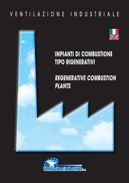
V E N T I L A Z I O N E I N D U S T R I A L E<br />
FILTRI A MANICHE AUTOPULENTI<br />
CON GETTO ARIA COMPRESSA<br />
IN CONTRO-CORRENTE<br />
SELF-CLEANING REVERSE JET<br />
BAG FILTERS
FILTRO A MANICHE AUTOPULENTI CON<br />
GETTO DI ARIA COMPRESSA IN CONTRO-<br />
CORRENTE<br />
1. TIPO DI TECNOLOGIA<br />
Filtrazione a secco.<br />
2. INQUINANTI ABBATTIBILI<br />
Tutti i tipi di polvere.<br />
3. LIMITI DI EMISSIONE RAGGIUNGIBILI<br />
Il campo di impiego è decisamente ampio, da polveri<br />
grossolane f<strong>in</strong>o a polveri submicromiche<br />
(0,20–0,25 micron)<strong>con</strong> rese di abbattimento che,<br />
<strong>con</strong> superfici filtranti adeguate superano il 97%.<br />
4. DESCRIZIONE DELLE APPARECCHIATURE<br />
E/O DEL PROCESSO<br />
È un depolveratore automatico, a tessuto, adatto<br />
per funzionamento <strong>con</strong>t<strong>in</strong>uo (24 ore su 24), <strong>con</strong><br />
pulizia del tessuto filtrante <strong>in</strong> <strong>con</strong>trocorrente.<br />
Può trattare <strong>aria</strong> <strong>con</strong>tenente polveri molto f<strong>in</strong>i, <strong>con</strong>servando<br />
un rendimento di captazione assai elevato,<br />
anche per particelle aventi dimensioni <strong>in</strong>feriori<br />
a l micron.<br />
Con l’impiego di particolari tessuti, può essere<br />
impiegato per temperature massime di esercizio<br />
superiori anche a 200°C. (fibre di vetro).<br />
La costruzione prevede <strong>in</strong>fatti pannelli componibili.<br />
Questo facilita il trasporto e il montaggio, e rende<br />
possibile e semplice l’eventuale ampliamento<br />
del depolveratore anche dopo l’<strong>in</strong>stallazione.<br />
Il depolveratore è dotato di ampi portelli di ispezione,<br />
aperti sul cielo del depolveratore stesso o sulla<br />
tramoggia sottostante alle celle, che <strong>con</strong>sentono di<br />
eseguire <strong>con</strong> estrema facilità le operazioni di manutenzione<br />
o, comunque, il <strong>con</strong>trollo delle parti <strong>in</strong>terne.<br />
Elementi filtranti sono costituiti da cestelli opportunamente<br />
dimensionati e da una manica costituita<br />
da un particolare tessuto filtrante le cui caratteristiche<br />
vengono determ<strong>in</strong>ate <strong>in</strong> funzione di ogni specifica<br />
applicazione. L’aggancio dell’elemento filtrante<br />
ai «Venturi», solidali <strong>con</strong> il diaframma superiore,<br />
è pratico e di facile e veloce esecuzione: particolare<br />
questo che <strong>con</strong>sente di <strong>con</strong>tenere notevolmente<br />
i costi di manutenzione.<br />
Il ciclo di lavaggio è v<strong>aria</strong>bile <strong>in</strong> funzione delle reali<br />
necessità dell’impianto al quale il depolveratore è<br />
collegato. Il dispositivo di <strong>con</strong>trollo è <strong>con</strong>cepito <strong>in</strong><br />
modo da poter ottenere sia la v<strong>aria</strong>zione del tempo<br />
di lavaggio sia la v<strong>aria</strong>zione della frequenza dell’<strong>aria</strong>.<br />
Questa elasticità di funzionamento facilita i fenomeni<br />
fisici se<strong>con</strong>dari derivanti dal lavaggio <strong>in</strong> <strong>con</strong>trocorrente<br />
che provocano il distacco dello strato<br />
di polvere depositato sul tessuto, <strong>in</strong> modo da pulire<br />
lo stesso <strong>in</strong> profondità, restituendo al tessuto filtrante<br />
il massimo grado di permeabilità.<br />
2<br />
SELF-CLEANING, REVERSE -JET<br />
BAG FILTER<br />
1. TYPE OF TECHNOLOGY<br />
Dry collections.<br />
2. CONTAMINANTS WHICH CAN BE REMOVED<br />
All types of dust.<br />
3. EMISSION LIMITS POSSIBLE<br />
The range of application is decidedly wide, from<br />
coarse dusts to submicronic dusts (0.20–0.25<br />
micron) with collection efficiencies which, with<br />
adequate filter surfaces, can exceed 97%.<br />
4. DESCRIPTION OF THE EQUIPMENT<br />
AND/OR PROCESS<br />
This is an automatic fabric dust collector,<br />
designed for <strong>con</strong>t<strong>in</strong>uous duty (24 hours a day),<br />
with reverse flow clean<strong>in</strong>g of the filter fabric.<br />
It can handles air <strong>con</strong>ta<strong>in</strong><strong>in</strong>g very f<strong>in</strong>e dusts<br />
ma<strong>in</strong>ta<strong>in</strong><strong>in</strong>g a fairly high capture efficiency, even<br />
<strong>in</strong> the case of particles with diameter less than l<br />
micron.<br />
When special fabrics are adopted, the dust collector<br />
can be used for maximum operat<strong>in</strong>g temperatures<br />
also up to 200°C. (glass fibres).<br />
The <strong>con</strong>struction is based on modular panels. This<br />
makes for easier transport and assembly while the<br />
dust collector can easily be extended also after<br />
<strong>in</strong>stallation.<br />
The dust collector is provided with ample <strong>in</strong>spection<br />
doors, open<strong>in</strong>g at the top of the dust collector<br />
or on the hopper under the cells. Thus ma<strong>in</strong>tenance<br />
is greatly simplified or at least it is easy to<br />
<strong>in</strong>spect the <strong>in</strong>ternal parts.<br />
The filter elements <strong>con</strong>sist of suitably sized wire<br />
cages and a bag of special filter fabric whose characteristics<br />
are determ<strong>in</strong>ed <strong>in</strong> accordance with<br />
each specific application. Connection of the filter<br />
elements to the «Venturis», <strong>in</strong>tegral with the top<br />
tube sheet is quick, easy and practical; such factor<br />
allows cutt<strong>in</strong>g down on ma<strong>in</strong>tenance costs.<br />
The clean<strong>in</strong>g cycle is v<strong>aria</strong>ble depend<strong>in</strong>g on the<br />
actual needs of the plant to which the dust collector<br />
is <strong>con</strong>nected. The <strong>con</strong>trol device is designed so<br />
as to allow v<strong>aria</strong>tion of both clean<strong>in</strong>g time and<br />
frequency of the air jet.<br />
This flexibility <strong>in</strong> operation facilitates the se<strong>con</strong>dary<br />
physical phenomena deriv<strong>in</strong>g from reverse<br />
flow clean<strong>in</strong>g which causes the dislodgement of<br />
the layer of dust built up on the fabric so that the<br />
latter is thoroughly cleaned thus restor<strong>in</strong>g the<br />
maximum degree of permeability to the filter fabric.<br />
In other words, it is possible to «calibrate» each fil-
In altre parole, è possibile «tarare» ogni filtro per le<br />
specifiche necessità e particolarità di ogni <strong>in</strong>stallazione,<br />
utilizzando <strong>in</strong> pieno le caratteristiche della<br />
macch<strong>in</strong>a e ottenendo qu<strong>in</strong>di, <strong>in</strong> ciascun particolare<br />
caso, il rendimento migliore.<br />
È <strong>in</strong>f<strong>in</strong>e possibile effettuare la pulizia dei tessuti filtranti<br />
a temperature diverse da quella ambiente, a<br />
se<strong>con</strong>da delle necessità dell’impianto, <strong>in</strong> relazione<br />
ai fenomeni di <strong>con</strong>densazione che vi si possono<br />
verificare.<br />
I nostri <strong>filtri</strong> vengono collegati <strong>in</strong> genere <strong>con</strong> <strong>in</strong>stallazione<br />
fissa o mobile ad una o più fonti di polveri<br />
all’orig<strong>in</strong>e, prima che esse si diffond<strong>in</strong>o nell’ambiente<br />
ed <strong>in</strong>qu<strong>in</strong><strong>in</strong>o il luogo di lavoro.<br />
4.1 Funzionamento<br />
L’<strong>aria</strong> polverosa entra nella camera filtrante e passa<br />
attraverso le <strong>maniche</strong> filtranti dall’esterno verso<br />
l’<strong>in</strong>terno.<br />
La pulizia avviene facendo fluire il <strong>getto</strong> di <strong>aria</strong><br />
<strong>compressa</strong> 6-7 atm. attraverso delle elettrovalvole<br />
dall’<strong>in</strong>terno verso l’esterno delle <strong>maniche</strong>.<br />
Ogni elettrovalvola è comandata <strong>con</strong> <strong>in</strong>tervalli<br />
sequenziali da 10-50 sec. da un pannello elettronico.<br />
Le perdite di carico delle <strong>maniche</strong> generalmente<br />
non superano i 120 mm. c.a.; il <strong>con</strong>sumo di <strong>aria</strong><br />
<strong>compressa</strong> è di circa 0,15 m 3 /ora per mq. di tessuto<br />
(2,5 lt/m<strong>in</strong>).<br />
5. APPLICAZIONI INDUSTRIALI TIPICHE<br />
Tutti i processi <strong>in</strong>dustriali ove sia presente polvere,<br />
aziende nei settori:<br />
- Ceramiche<br />
- Alimentari<br />
- Colorifici<br />
- Fonderie<br />
- Chimiche<br />
- Gomma<br />
- Saccarifere<br />
- Estrazione<br />
- Cementifici<br />
6. VANTAGGI E SVANTAGGI<br />
Vantaggi: costi di acquisto ed esercizio ridotti, semplicità<br />
d’uso, bassa necessità di manutenzione.<br />
Svantaggi: alti <strong>in</strong>gombri.<br />
ter for the specific needs and characteristics of<br />
each <strong>in</strong>stallation, thus mak<strong>in</strong>g full use of the<br />
mach<strong>in</strong>e’s characteristics and obta<strong>in</strong><strong>in</strong>g the best<br />
possible efficiency <strong>in</strong> each particular case.<br />
Lastly it is possible to clean the filter fabrics at temperatures<br />
other than ambient temperature accord<strong>in</strong>g<br />
to plant requirements, <strong>in</strong> relation to potential<br />
<strong>con</strong>densation phenomena.<br />
Our bag filters are normally <strong>con</strong>nected via a fixed<br />
or mobile <strong>in</strong>stallation to one or more sources generat<strong>in</strong>g<br />
the dust before the latter can be diffused <strong>in</strong><br />
the environment and pollute the workplace.<br />
Collection efficiencies achieved almost always<br />
exceed 99% and the dust collectors f<strong>in</strong>d optimum<br />
application <strong>in</strong> the follow<strong>in</strong>g <strong>in</strong>dustries:<br />
4.1 Operation<br />
The dust-laden air enters the filter chamber and<br />
flows through the filter bags from the outside<br />
towards the <strong>in</strong>side.<br />
Clean<strong>in</strong>g is performed by caus<strong>in</strong>g a jet of compressed<br />
air 6-7 atm. to flow, via solenoid valves,<br />
from the <strong>in</strong>side towards the outside of the filter<br />
bags.<br />
Each solenoid valve is commanded with sequential<br />
<strong>in</strong>tervals from 10-50 sec. via an electronic<br />
<strong>con</strong>trol panel.<br />
The pressure drops across the filter bags do not<br />
normally exceed 120 mm. water gauge; compressed<br />
air <strong>con</strong>sumption is approx. 0.15 m 3 /hour<br />
per sq.m. of fabric (2.5 lt/m<strong>in</strong>).<br />
5. TYPICAL INDUSTRIAL APPLICATIONS<br />
All <strong>in</strong>dustrial processes where dust is present, companies<br />
<strong>in</strong> the follow<strong>in</strong>g sectors:<br />
- Ceramics<br />
- Foodstuffs<br />
- Pa<strong>in</strong>ts<br />
- Foundries<br />
- Chemical process<strong>in</strong>g<br />
- Rubber<br />
- Sugar ref<strong>in</strong>eries<br />
- M<strong>in</strong><strong>in</strong>g<br />
6. ADVANTAGES AND DISADVANTAGES<br />
Advantages: lower purchas<strong>in</strong>g and runn<strong>in</strong>g costs,<br />
user-friendly, low ma<strong>in</strong>tenance requirements.<br />
Disadvantages: large overall size.<br />
3
7. CALCOLI E TABELLE<br />
Esempio di calcolo di un impianto di aspirazione<br />
(<strong>con</strong> filtro a <strong>maniche</strong>)<br />
7.1.1 Simboli<br />
HT = Resistenza totale del circuito o dell’impianto<br />
<strong>in</strong> mm. di H2O<br />
HD = Pressione/Resistenza d<strong>in</strong>amica dell’impianto<br />
HS = Pressione/Resistenza statica dell’impianto<br />
HT = HD + HS + resistenza dovuta a <strong>filtri</strong>, silenziatori<br />
etc.<br />
V 2<br />
HD = Yx –––<br />
2xg<br />
dove: V = Velocità di <strong>in</strong>gresso dell’<strong>aria</strong> o velocità<br />
massima dell’<strong>aria</strong> nell’impianto.<br />
Y = Peso specifico dell’ <strong>aria</strong> alla temperatura<br />
di 0°C (273 ° K) (~ 1,22 kg/m 3 ).<br />
g = Accelerazione di gravità 9,81 m/sec 2 .<br />
Resistenze statiche dei <strong>filtri</strong> di nostra produzione<br />
TIPO DI FILTRO PERDITA DI CARICO mm H2O<br />
CICLONI 50-70<br />
MUL TICICLONI 70-80<br />
SEPARATORI DI GOCCE 40<br />
BATTERIE RADIANTI 10-20<br />
SILENZIATORI 30<br />
FILTRI A SETTO METALLICO 5-10<br />
FILTRI STATICI 100-150<br />
SCRUBBER A PIATTI O CORPI 150-200<br />
SCRUBBER VENTURI 300-350<br />
FILTRI A TASCHE 40-50<br />
FILTRI ELETTROSTATICI 20<br />
FILTRI A CARBONE ATTIVO 100-250<br />
FILTRI A CARTUCCE 100-150<br />
FILTRI A MANICHE 100-150<br />
HS = Resistenza lungo la l<strong>in</strong>ea dell’impianto più<br />
sfavorita. In base ai diametri di tale l<strong>in</strong>ea e<br />
alle velocità dell’<strong>aria</strong> relative a questi diametri<br />
si ricava la perdita di carico <strong>in</strong> mm. H2O,<br />
per ogni metro di tubazione di quel diametro.<br />
Moltiplicando tale valore per la lunghezza<br />
<strong>in</strong> metri di tubo di quel diametro si<br />
ottiene la resistenza che l’<strong>aria</strong> <strong>in</strong><strong>con</strong>tra nell’<br />
attraversare quel pezzo di l<strong>in</strong>ea. Tenere <strong>con</strong>to<br />
che:<br />
- le curve a 90° offrono una resistenza al passaggio<br />
dell’<strong>aria</strong> pari alla resistenza offerta da<br />
un tubo rettil<strong>in</strong>eo dello stesso diametro ma<br />
<strong>con</strong> una lunghezza pari a 12 volte il diametro<br />
stesso;<br />
- i tubi flessibili <strong>in</strong> genere offrono una resistenza<br />
al passaggio dell’ <strong>aria</strong> pari alla resistenza<br />
offerta da un tubo rettil<strong>in</strong>eo dello stesso<br />
diametro ma <strong>con</strong> lunghezza pari a due<br />
volte la lunghezza del tubo flessibile.<br />
4<br />
7. CALCULATIONS AND TABLES<br />
Example of calculation of an exhaust plant<br />
(with bag filter)<br />
7.1.1 Symbols<br />
HT = Total resistance of the circuit or plant <strong>in</strong> mm.<br />
of H 2 O<br />
HD = Pressure/Dynamic resistance of the plant<br />
HS = Pressure/Static resistance of the plant<br />
HT = HD + HS + resistance due to filters, silencers,<br />
etc.<br />
V 2<br />
HD = Yx –––<br />
2xg<br />
where: V = Air <strong>in</strong>let velocity or max. velocity of<br />
the air <strong>in</strong> the plant.<br />
Y = Specific gravity of air at the temperature<br />
of 0°C (273 °K) (~ 1.22 kg/m 3 ).<br />
g = Acceleration of gravity 9.81 m/sec 2 .<br />
Static resistance of filters manufactured by us<br />
FILTER TYPE PRESSURE DROP mm H2O<br />
CYCLONES 50-70<br />
MULTICYCLONES 70-80<br />
MIST ELIMINATORS 40<br />
RADIANT COIL TYPE 10-20<br />
SILENCERS 30<br />
FILTERS W. METAL MESH 5-10<br />
STATIC FILTERS 100-150<br />
PACKED/ IMPINGEMENT<br />
PLATE SCRUBBERS 150-200<br />
VENTURI SCRUBBERS 300-350<br />
ENVELOPE FILTERS 40-50<br />
ELECTROSTATIC PRECIPITATORS 20<br />
ACTIVATED CARBON FILTERS 100-250<br />
CARTRIDGE FILTERS 100-150<br />
BAG FILTERS 100-150<br />
HS = Resistance along the most unfavourable l<strong>in</strong>e<br />
of the plant. Depend<strong>in</strong>g on the diameters of<br />
such l<strong>in</strong>e and relative air velocities the pressure<br />
drop <strong>in</strong> mm. H2O is determ<strong>in</strong>ed for each<br />
metre of duct of that particular diameter.<br />
Multiply<strong>in</strong>g such value by the length <strong>in</strong><br />
metres of duct of that diameter, gives the resistance<br />
encountered by the air when follow<strong>in</strong>g<br />
through that part of the l<strong>in</strong>e. Bear <strong>in</strong> m<strong>in</strong>d:<br />
- 90° elbows offer resistance to the air flow<br />
equal to the resistance offered by a straight<br />
duct of the same diameter but with a length<br />
equal to 12 times the actual diameter;<br />
- flexible hoses or duct normally offer a resistance<br />
to air flow equal to the resistance offered<br />
by a straight duct of the same diameter<br />
but with length equal to twice the length of<br />
the flexible hose of duct.
7.1.2 Esempio di calcolo<br />
Dovendo calcolare un impianto di aspirazione e<br />
abbattimento si dovranno <strong>con</strong>oscere i seguenti dati:<br />
- tipo di polvere<br />
- posizioni delle fonti delle polveri<br />
- granulometria della polvere<br />
- posizione dell’abbattitore<br />
- temperatura dell’<strong>aria</strong> polverosa<br />
- altitud<strong>in</strong>e dell’impianto<br />
Abbiamo stabilito:<br />
Posizione 1: tavolo di lavoro<br />
Posizione 2: levigatrice a colonna<br />
Polveri da aspirare<br />
ed abbattere: polveri di ferro<br />
Granulometria: sopra i 10 micron<br />
Temperatura: ambiente<br />
7.1.3 Determ<strong>in</strong>iamo la portata dell’impianto<br />
A) Per il tavolo di lavoro n. 4 fessure <strong>con</strong> le<br />
seguenti dimensioni:<br />
50 mm. per 2000 mm. di lunghezza, (superficie<br />
di 0,4 m 2 ).<br />
Velocità alla fessura: 2 mt/sec. equivalente ad<br />
una portata di: 0,8 m 3 /sec.<br />
B) Per la levigatrice a colonna avente 2 cappe di<br />
captazione <strong>con</strong> sezione di m 2 . 0,05 cadauna<br />
avremo:<br />
Velocità alla fessura: 4 mt/sec. equivalente a<br />
una portata di: 0,2 m 2 /sec.<br />
Si moltiplica per 2. Portata totale: 0,4 m 3 /sec.<br />
per i due dischi della levigatrice.<br />
C) Avremo una portata totale dell’impianto:<br />
A + B (0,8 + 0,4): 1,2 m 3 /sec. che, moltiplicando<br />
per 3.600, dà una portata di 4.320 che si<br />
arrotonda a 4.400 m 3 /h.<br />
7.1.4 Determ<strong>in</strong>iamo i diametri dell’impianto<br />
A) Per il tavolo abbiamo una portata di 0,8<br />
m 3 /sec. Stabiliamo una velocità di 25 mt/sec.<br />
Dividendo la portata per la velocità (0,8÷25)<br />
abbiamo una sezione pari a 0,032 m 2 - equivalente<br />
ad un diametro di mt 0,2 che portiamo<br />
per comodità a mm. 200.<br />
B) Per la levigatrice abbiamo una portata di 0,4<br />
m 3 /sec. Stabiliamo una velocità di 25 mt/sec.<br />
Dividendo la portata per la velocità (0,4÷25)<br />
abbiamo una sezione pari a 0,016 m 2 - equivalente<br />
ad un diametro di mt. 0,14 che portiamo<br />
per comodità a mm. 140.<br />
C) Dalla somma dei diametri delle due macch<strong>in</strong>e,<br />
cioé Ø 200 mm. e levigatrice Ø 140 mm., avremo<br />
se<strong>con</strong>do tabella a pag. 31 per il primo il<br />
modulo 8, per il se<strong>con</strong>do il modulo 4.<br />
Sommiamo i due moduli e ne otterremo uno di<br />
12, pari a un diametro di 245 mm. che si arrotonda<br />
a 250 mm.<br />
7.1.2 Example of calculation<br />
The follow<strong>in</strong>g data should be known for calculat<strong>in</strong>g<br />
an exhaust and dust collect<strong>in</strong>g plant:<br />
- type of dust<br />
- positions of the dust sources<br />
- particle size of the dust<br />
- dust collector position<br />
- temperature of the dust-laden air<br />
- altitude of the plant<br />
We have established:<br />
Position 1: work table<br />
Position 2: floor disc sander<br />
Dusts to exhaust<br />
and remove: iron dusts<br />
Particle size: above 10 micron<br />
Temperature: ambient<br />
7.1.3 Determ<strong>in</strong>e the plant flow capacity<br />
A) For the work table with 4 slots of the follow<strong>in</strong>g<br />
size:<br />
50 mm. for 2000 mm. of length, (surface of 0.4<br />
m 2 ).<br />
Velocity at the slot: 2 m/sec. equivalent to a flow<br />
rate of: 0.8 m 3 /sec.<br />
B) For the floor disc sander hav<strong>in</strong>g 2 captur<strong>in</strong>g<br />
hoods, each with section of 0.05 m 2 we have:<br />
Velocity at the slot: 4 m/sec. equivalent to a flow<br />
rate of: 0.2 m 2 /sec.<br />
Multiply by 2. Total flow: 0.4 m 3 /sec. for the two<br />
sand<strong>in</strong>g discs.<br />
C) We have a total flow for the plant as follows:<br />
A + B (0.8 + 0.4): 1.2 m 3 /sec. which, when multiplied<br />
by 3600, gives a flow of 4320 rounded<br />
up to 4400 m 3 /h.<br />
7.1.4 Determ<strong>in</strong>e the diameters of the plant<br />
A) For the work table we have a flow of 0.8 m 3 /sec.<br />
Consider a velocity of 25 m/sec. Then divid<strong>in</strong>g<br />
the flow by the velocity (0.8 to 25) we obta<strong>in</strong> a<br />
section equal to 0.032 m 2 – equivalent to a<br />
diameter of 0.2 m which, for <strong>con</strong>venience, we<br />
shall <strong>con</strong>vert to 200 mm.<br />
B) For the sander we have a flow 0.4 m 3 /sec.<br />
Consider a velocity of 25 m/sec. Then divid<strong>in</strong>g<br />
the flow by the velocity (0.4 to 25) we obta<strong>in</strong> a<br />
section equal to 0.016 m 2 - equivalent to a<br />
diameter of. 0.14 m which, for <strong>con</strong>venience, we<br />
shall <strong>con</strong>vert to 140 mm.<br />
C) From the sum of the diameters of the two<br />
mach<strong>in</strong>es, i.e. dia. 200 mm. and dia. 140 mm.<br />
(sand<strong>in</strong>g mach<strong>in</strong>e), we shall have, accord<strong>in</strong>g to<br />
the table on page 31, a module of 8 for the first<br />
and a module of 4 for the se<strong>con</strong>d. On summ<strong>in</strong>g<br />
the two modules we obta<strong>in</strong> one of 12, equal to a<br />
diameter of 245 mm. which is rounded up to<br />
250 mm.<br />
5
D) Stabiliamo l’<strong>in</strong>gresso al filtro che deve avere<br />
una velocità non superiore a 10 mt/sec., avremo<br />
dalla divisione della portata di 1,2 m 3 /sec.<br />
e dalla velocità di 10 mt/sec. una sezione di<br />
0,12 m 2 pari ad un rettangolo di 600 mm x 200<br />
mm. di altezza.<br />
E) Stabiliamo <strong>in</strong>f<strong>in</strong>e il diametro della tubazione di<br />
collegamento filtro/ventilatore e cam<strong>in</strong>o di<br />
espulsione <strong>aria</strong> <strong>in</strong> atmosfera. Per non creare<br />
fonti di rumore la velocità al cam<strong>in</strong>o dev’essere<br />
<strong>in</strong>feriore a 13 mt/sec. Dalla divisione della<br />
portata di 1,2 m 3 /sec. e la velocità di 13<br />
mt/sec., avremo un diametro di 0,345 mt che<br />
arrotondiamo a 350 mm.<br />
7.1.5 Calcoliamo le perdite di carico di tutto il<br />
circuito<br />
Avremo delle tubazioni di vari diametri, diritte, curve,<br />
diramazioni, cappe e <strong>in</strong> questo caso un filtro<br />
del tipo autopulente a <strong>maniche</strong>. A questo punto<br />
sistemiamo una dist<strong>in</strong>ta <strong>con</strong>siderando il tratto più<br />
lungo ed accidentale del percorso.<br />
Tubo Ø 200 mm. mt 2+3 = 5<br />
(V =25) x 4,5 mm H2O Tubo Ø 250 mm. mt 3+2,5 = 5,5<br />
22,5<br />
(V =25) x 3 mm H2O Tubo Ø 350 mm. mt 5+2+8 = 15<br />
16,5<br />
(V =13) x 0,5 mm H2O Curve n. 5 x 0,5 x HD<br />
7,5<br />
97,5<br />
Diramazioni n.1 x 0,7 x D<br />
1,22x25<br />
27,5<br />
2<br />
HD D<strong>in</strong>amica –––––––––– = 38,9<br />
19,62<br />
che arrotondiamo a 39<br />
Imbocco alla presa = 1/2 HD 19,25<br />
Filtro autopulente (max perdite) 120<br />
––––<br />
Totale 350 mm H 2 O<br />
Per quanto riguarda le perdite di carico delle tubazioni<br />
diritte si veda la tabella a pag<strong>in</strong>a 32 e dall’<strong>in</strong>crocio<br />
del diametro delle tubazioni e dalla velocità,<br />
si otterrà sulla discesa le perdite di carico per<br />
ogni metro di tubo. Per le perdite delle curve e delle<br />
diramazioni si veda la tabella a pag<strong>in</strong>a 30.<br />
Dalle tabelle e curve di prestazioni stabiliamo la<br />
potenza di un ventilatore attraversato da <strong>aria</strong> pulita<br />
<strong>con</strong> un rendimento sull’80% <strong>con</strong> la formula:<br />
Q x HT 1,2 x 350 420<br />
CV ASS = ––––––– = ––––––––– = ––––– = 7<br />
75 x n 75 x 0,80 60<br />
6<br />
D) Suppose we establish that the filter <strong>in</strong>let must not<br />
have a velocity exceed<strong>in</strong>g 10 m/sec., then from<br />
the division of the flow of 1.2 m 3 /sec. and of the<br />
velocity of 10 m/sec. we obta<strong>in</strong> a section of 0.12<br />
m 2 equal to a rectangle of 600 mm x 200 mm.<br />
<strong>in</strong> height.<br />
E) Lastly we fix the diameter of the duct <strong>con</strong>nect<strong>in</strong>g<br />
filter/fan to the stack discharg<strong>in</strong>g the air <strong>in</strong><br />
the atmosphere. In order not to create noise<br />
sources, the velocity <strong>in</strong> the stack should be less<br />
than 13 m/sec. By the division of the flow of 1.2<br />
m 3 /sec. and velocity of 13 m/sec., we obta<strong>in</strong> a<br />
diameter of 0.345 m rounded up to 350 mm.<br />
7.1.5 Calculate the pressure drops across the<br />
entire circuit<br />
We have ducts of various diameters, straight sections,<br />
elbows, branches, hoods and <strong>in</strong> this case a<br />
self-clean<strong>in</strong>g bag filter. We now make up a list <strong>con</strong>sider<strong>in</strong>g<br />
the longest and most uneven section of the<br />
path.<br />
Duct dia. Ø 200 mm. mt 2+3 = 5<br />
(V =25) x 4,5 mm H2O Duct dia. Ø 250 mm. mt 3+2,5 = 5,5<br />
22,5<br />
(V =25) x 3 mm H2O Duct dia. Ø 350 mm. mt 5+2+8 = 15<br />
16,5<br />
(V =13) x 0,5 mm H2O 5 elbows 0.5 x HDD<br />
7,5<br />
97,5<br />
1 branch x 0.7 x D<br />
1,22x25<br />
27,5<br />
2<br />
Dynamic HD –––––––––– = 38,9<br />
19,62<br />
rounded up to 39<br />
Air <strong>in</strong>take <strong>in</strong>let = 1/2 HD 19,25<br />
Self-clean<strong>in</strong>g filter<br />
(max pressure drops) 120<br />
––––<br />
Total 350 mm H 2 O<br />
As regards the pressure drops for the straight duct,<br />
see table on page 32. By the <strong>in</strong>tersection of the duct<br />
diameter and the velocity, we obta<strong>in</strong> the pressure<br />
drops on the down part for each metre of ducts. For<br />
pressure drops across the elbows and branches, see<br />
table on page 30.<br />
From the tables and performance curves, we can<br />
determ<strong>in</strong>e the power rat<strong>in</strong>g of a fan through which<br />
clean air flows, with an efficiency of 80% through<br />
the follow<strong>in</strong>g formula:<br />
Q x HT 1,2 x 350 420<br />
CV ASS = ––––––– = ––––––––– = ––––– = 7<br />
75 x n 75 x 0,80 60
Dove:<br />
CV ASS =Potenza assorbita <strong>in</strong> CV (a regime)<br />
Q =Portata <strong>in</strong> m 3 /sec.<br />
HT =Prevalenza totale<br />
n =Rendimento (vedi curve ventilatore<br />
oppure pag. 104)<br />
CV ASS = 7 CV + 20% per trasmissione; avremo 8,4<br />
CV qu<strong>in</strong>di <strong>in</strong>stalleremo 10 CV equivalenti a 7,5 KW.<br />
Inf<strong>in</strong>e stabiliamo il filtro.<br />
Dalla tabella a pag. 44 avremo una velocità di filtrazione<br />
di 0,03 mt/sec.<br />
Dalla divisione della portata 1,2 m 3 /sec. e della<br />
velocità di filtrazione avremo m 2 40 di tessuto filtrante<br />
del tipo e spessori da stabilire di volta <strong>in</strong> volta.<br />
Considerando <strong>maniche</strong> <strong>con</strong> Ø 123 alte 2500, equivalenti<br />
a circa 1 m 2 cadauna, avremo n. 40 <strong>maniche</strong><br />
totali.<br />
Calcolo della perdita di carico<br />
per s<strong>in</strong>gola manica (se<strong>con</strong>do Rietsche)<br />
Portata d’<strong>aria</strong> (m 3 )<br />
H = K x ––––––––––––––––<br />
Superficie (m 2 )<br />
dove K = coefficiente v<strong>aria</strong>bile da 0,015<br />
(maglia larga) a 0,03 (maglia stretta)<br />
8. INFORMAZIONI SUI COSTI<br />
Il costo specifico di acquisto per applicazioni che<br />
non richiedono accorgimenti costuttivi particolari è<br />
compreso tra 160 e 200 €/m2 di superficie filtrante.<br />
Il costo di esercizio del filtro a <strong>maniche</strong>, escludendo<br />
i costi di captazione gas derivanti dal ventilatore,<br />
è limitato al <strong>con</strong>sumo dell’<strong>aria</strong> <strong>compressa</strong><br />
utilizzata per la pulizia delle <strong>maniche</strong>.<br />
Where:<br />
HP <strong>con</strong>s. =Power <strong>con</strong>sumption <strong>in</strong> HP (<strong>in</strong> normal<br />
operation)<br />
Q =Flow rate <strong>in</strong> m 3 /sec.<br />
HT =Total head<br />
n =Efficiency (see fan curves or else page<br />
104)<br />
HP <strong>con</strong>s. = 7 HP + 20% by transmission; we shall<br />
have 8.4 HP therefore 10 HP will be <strong>in</strong>stalled equivalent<br />
to 7.5 KW.<br />
Lastly we shall decide the filter size:<br />
From the table on page 44 we have a filtration<br />
velocity of 0.03 m/sec.<br />
Based on the division of the flow rate 1.2 m 3 /sec.<br />
and filtration velocity, we shall have 40 m 2 of filter<br />
fabric of type and thickness to be determ<strong>in</strong>ed <strong>in</strong><br />
each <strong>in</strong>dividual case.<br />
Assum<strong>in</strong>g the filter bags to be with dia. 123 and<br />
height 2500 mm high, each equivalent to approx. 1<br />
m 2 , there will be a total of 40 filter bags.<br />
Calculation of the pressure drop<br />
for <strong>in</strong>dividual filter bag (accord<strong>in</strong>g to Rietsche)<br />
Air flow (m 3 )<br />
H = K x ––––––––––––––––<br />
Surface (m 2 )<br />
where K = coefficient v<strong>aria</strong>ble from 0.015<br />
(coarse mesh) to 0.03 (f<strong>in</strong>e mesh)<br />
8. INFORMATION REGARDING COST<br />
The specific purchas<strong>in</strong>g cost for applications not<br />
requir<strong>in</strong>g special design arrangements lies between<br />
160 and 200 €/m2 of the filter surface. Runn<strong>in</strong>g<br />
costs for bag filters, exclud<strong>in</strong>g costs for captur<strong>in</strong>g<br />
gases com<strong>in</strong>g from the fan, are limited to compressed<br />
air <strong>con</strong>sumption for bag clean<strong>in</strong>g.<br />
7
Filtro a <strong>maniche</strong> autopulente per la filtrazione di polveri di<br />
res<strong>in</strong>a poliestere. Portata d’<strong>aria</strong> 15.000 Nm 3 /h<br />
8<br />
Self-clean<strong>in</strong>g bag filter for filtration of polyester res<strong>in</strong> dusts.<br />
Air flow rate 15,000 Nm 3 /h
FILTRI A MANICHE<br />
AUTOPULENTI<br />
TABELLA COMPARATIVA / COMPARATIVE TABLE<br />
Filtri a <strong>maniche</strong> di dimensioni maggiori possono essere progettati<br />
e realizzati su richiesta<br />
DIMENSIONI / DIMENSIONS<br />
SELF CLEANING<br />
BAG FILTERS<br />
Filtro tipo Superficie mq. N. <strong>maniche</strong> Lunghezza <strong>maniche</strong> A B C Scarico tipo<br />
Filter type Surface sq.m N. bags Bag length A B C Type of unload<strong>in</strong>g<br />
30/5 30 30 2500 1050 900 4700 1 secchiello / 1 b<strong>in</strong><br />
30/5/R 24 30 2000 1050 900 4200 1 secchiello / 1 b<strong>in</strong><br />
42/6 42 42 2500 1200 1050 4700 1 secchiello / 1 b<strong>in</strong><br />
42/6/R 33 42 2000 1200 1050 4200 1 secchiello / 1 b<strong>in</strong><br />
48/6 48 48 2500 1400 1050 4700 1 secchiello / 1 b<strong>in</strong><br />
48/6/R 38 48 2000 1400 1050 4200 1 secchiello / 1 b<strong>in</strong><br />
60/6 60 60 2500 1050 1700 5700 1 secchiello / 1 b<strong>in</strong><br />
60/6/R 48 60 2000 1050 1700 5200 1 secchiello / 1 b<strong>in</strong><br />
70/7 70 70 2500 1250 1700 5700 1 secchiello / 1 b<strong>in</strong><br />
70/7/R 55 70 2000 1250 1700 5200 1 secchiello / 1 b<strong>in</strong><br />
80/8 80 80 2500 1400 1700 5700 1 secchiello / 1 b<strong>in</strong><br />
80/8/R 64 80 2000 1400 1700 5200 1 secchiello / 1 b<strong>in</strong><br />
90/9 90 90 2500 1550 1700 5700 1 secchiello / 1 b<strong>in</strong><br />
90/9/R 71 90 2000 1550 1700 5200 1 secchiello / 1 b<strong>in</strong><br />
100/10 100 100 2500 1700 1700 5700 1 secchiello / 1 b<strong>in</strong><br />
100/10/R 80 100 2000 1700 1700 5200 1 secchiello / 1 b<strong>in</strong><br />
120/12 120 120 2500 2000 1700 5700 2 secchielli / 2 b<strong>in</strong>s<br />
120/12/R 96 120 2000 2000 1700 5200 2 secchielli / 2 b<strong>in</strong>s<br />
140/14 140 140 2500 2350 1700 5700 2 secchielli / 2 b<strong>in</strong>s<br />
140/14/R 110 140 2000 2350 1700 5200 2 secchielli / 2 b<strong>in</strong>s<br />
160/16 160 160 2500 2650 1700 5700 coclea /screw <strong>con</strong>veyor<br />
160/61/R 128 160 2000 2650 1700 5200 coclea /screw <strong>con</strong>veyor<br />
180/18 180 180 2500 3000 1700 5700 coclea /screw <strong>con</strong>veyor<br />
180/18/R 142 180 2000 3000 1700 5200 coclea /screw <strong>con</strong>veyor<br />
200/20 200 200 2500 3300 1700 5700 coclea /screw <strong>con</strong>veyor<br />
200/20/R 158 200 2000 3300 1700 5200 coclea /screw <strong>con</strong>veyor<br />
250/25 250 250 2500 4100 1700 5700 coclea /screw <strong>con</strong>veyor<br />
250/25/R 191 250 2000 4100 1700 5200 coclea /screw <strong>con</strong>veyor<br />
300/30 300 300 2500 4900 1700 5700 coclea /screw <strong>con</strong>veyor<br />
300/30/R 236 300 2000 4900 1700 5200 coclea /screw <strong>con</strong>veyor<br />
350/35 350 350 2500 5700 1700 5700 coclea /screw <strong>con</strong>veyor<br />
350/35/R 275 350 2000 5700 1700 5200 coclea /screw <strong>con</strong>veyor<br />
400/40 400 400 2500 6500 1700 5700 coclea /screw <strong>con</strong>veyor<br />
400/40/R 314 400 2000 6500 1700 5200 coclea /screw <strong>con</strong>veyor<br />
Larger bag filters can be designed and built on request.<br />
N.B. Bear <strong>in</strong> m<strong>in</strong>d that when read<strong>in</strong>g the tables, the values are given with the European decimal notation; for English readers the comma should be taken as the decimal po<strong>in</strong>t.<br />
9
10<br />
LEGENDA<br />
1. ELETTROVALVOLE<br />
2. TUBO POLMONE<br />
3. GRUPPO FILTRANTE<br />
4. ARRIVO ARIA COMPRESSA<br />
5. TUBO VENTURI<br />
6. CORPO FILTRO<br />
7. MANICA<br />
8. QUADRO COMANDO ELETTROVALVOLE<br />
9. MANOMETRO DIFFERENZIALE<br />
10. SCARICO POLVERI<br />
LEGEND<br />
1. SOLENOID VALVE<br />
2. AIR MANIFOLD<br />
3. SET OF FILTER BAGS<br />
4. COMPRESSED AIR INLET<br />
5. VENTURI NOZZLE<br />
6. FILTER HOUSING<br />
7. FILTER BAG<br />
8. SOLENOID VALVE CONTROL PANEL<br />
9. DIFFERENTIAL PRESSURE GAUGE<br />
10. DUST UNLOADING
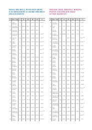
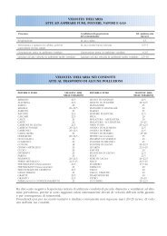
TIPI DI TESSUTO PER MANICHE<br />
E VELOCITA' MEDIE DI FILTRAZIONE PER POLVERI E FUMI<br />
INQUINANTE TIPO DI FELTRO VELOCITA' DI FILTRAZ.<br />
(mt/sec) m<strong>in</strong>./max.<br />
OSSIDO DI ALLUMINIO feltro poliestere 0,019 - 0,026<br />
BAUXITE feltro poliestere 0,019 - 0,026<br />
CARBONE CALCINATO feltro poliestere antistatico 0,019 - 0,026<br />
CARBONE feltro poliestere 0,019 - 0,026<br />
CEMENTO CRUDO feltro poliestere 0,019 - 0,026<br />
CEMENTO FINITO feltro poliestere 0,019 - 0,026<br />
CEMENTO MACINATO feltro poliestere 0,019 - 0,026<br />
FRANTUMAZIONE FERRO CROMO feltro poliestere 0,023 - 0,030<br />
ARGILLA VERDE feltro poliestere 0,023 - 0,030<br />
ARGILLA SILICEA VETRIFICATA feltro poliestere 0,030 - 0,038<br />
PORCELLANA feltro poliestere 0,023 - 0,030<br />
FARINA feltro poliestere o lana 0,030 - 0,038<br />
GRANAGLIE CEREALI feltro poliestere o lana 0,038 - 0,045<br />
GRAFITE feltro poliestere 0,011 - 0,019<br />
GESSO IDRATO feltro poliestere 0,023 - 0,030<br />
FUMI DI OSSIDO DI PIOMBO feltro poliestere nomex 0,015 - 0,023<br />
CALCE feltro poliestere 0,023 - 0,030<br />
MACINAZIONE CALCARE feltro poliestere 0,030 - 0,030<br />
FUMI METALLURGICI feltro poliestere dralon o nomex 0,015 - 0,023<br />
MICA<br />
PIGMENTI PER VERNICI<br />
feltro poliestere 0,030 - 0,034<br />
POLVERI FENOLICHE PER STAMPAGGIO feltro poliestere 0,011 - 0,019<br />
MATERIE PLASTICHE ANIME IN SABBIA feltro poliestere antistatico 0,023 - 0,030<br />
POLIVINILCLORURO (PVC) feltro poliestere, lana 0,023 - 0,026<br />
MACINAZIONE REFRATTARI feltro poliestere 0,023 - 0,030<br />
SABBIA feltro poliestere 0,023 - 0,030<br />
CARBURO DI SILICIO feltro <strong>in</strong> lana 0,023 - 0,030<br />
POLVERI DI DETERSIVI E SAPONI feltro poliestere, polipropilene 0,023 - 0,026<br />
SOIA feltro poliestere, lana 0,023 - 0,030<br />
AMIDO feltro polipropilene 0,023 - 0,030<br />
ZUCCHERO tessuto poliestere, feltro polipropilene 0,023 - 0,030<br />
TALCO feltro poliestere 0,023 - 0,030<br />
POLVERI DI TANTANIO feltro poliestere 0,015 - 0,023<br />
TABACCO feltro poliestere antistatico 0,023 - 0,030<br />
FARINA DI LEGNO feltro poliestere antistatico 0,023 - 0,030<br />
SEGATURA DI LEGNO feltro poliestere, cotone 0,023 - 0,030<br />
ZINCO METALLICO feltro poliestere, nomex 0,023 - 0,030<br />
OSSIDO DI ZINCO feltro poliestere 0,015 - 0,023<br />
OSSIDO DI TITANIO feltro poliestere 0,011 - 0,015<br />
POLVERE DI MARMO feltro agugliato <strong>in</strong> poliestere 0,011 - 0,015<br />
11
12<br />
TYPES OF FABRIC FOR FILTER BAGS AND AVERAGE FILTRATION<br />
VELOCITIES FOR DUST AND FUMES<br />
CONTAMINANT TYPE OF FELT FILTRAT. VELOCITY<br />
(mt/sec) m<strong>in</strong>./max.<br />
ALUMINIUM OXIDE polyester felt 0,019 - 0,026<br />
BAUXITE polyester felt 0,019 - 0,026<br />
CALCINATED COAL antistatic polyester felt 0,019 - 0,026<br />
COAL polyester felt 0,019 - 0,026<br />
RAW CEMENT polyester felt 0,019 - 0,026<br />
FINISHED CEMENT polyester felt 0,019 - 0,026<br />
GROUND CEMENT polyester felt 0,019 - 0,026<br />
IRON - CHROMIUM CHRUSHING polyester felt 0,023 - 0,030<br />
GREEN CLAY polyester felt 0,023 - 0,030<br />
VITRIFIED SILCA CLAY polyester felt 0,030 - 0,038<br />
PORCELAIN polyester felt 0,023 - 0,030<br />
FLOUR polyester felt or wool 0,030 - 0,038<br />
GRAIN CEREALS polyester felt or wool 0,038 - 0,045<br />
GRAPHITE polyester felt 0,011 - 0,019<br />
HYDRATED GYPSUM polyester felt 0,023 - 0,030<br />
LEAD OXIDE FUMES polyester felt, nomex 0,015 - 0,023<br />
LIME polyester felt 0,023 - 0,030<br />
LIMESTONE GRINDING polyester felt 0,030 - 0,030<br />
METALLURGICAL FUMES polyester felt, dralon or nomex 0,015 - 0,023<br />
MICA<br />
PAINT PIGMENTS<br />
polyester felt 0,030 - 0,034<br />
PHENOLIC POWDERS FOR MOULDING polyester felt 0,011 - 0,019<br />
PLASTICS SAND CORES antistatic polyester felt 0,023 - 0,030<br />
POLYVINYL CHLORIDE(PVC) polyester felt, wool 0,023 - 0,026<br />
REFRACTORY MATERIAL GRINDING polyester felt 0,023 - 0,030<br />
SAND polyester felt 0,023 - 0,030<br />
SILICON CARBIDE wool felt 0,023 - 0,030<br />
DETERGENT POWDERS AND SOAPS polyester, polypropylene felt 0,023 - 0,026<br />
SOYA polyester felt, wool 0,023 - 0,030<br />
STARCH polypropylene felt 0,023 - 0,030<br />
SUGAR polyester fabric, polypropylene 0,023 - 0,030<br />
TALC polyester felt 0,023 - 0,030<br />
TANTANIUM DUSTS polyester felt 0,015 - 0,023<br />
TOBACCO antistatic polyester felt 0,023 - 0,030<br />
WOOD FLOUR antistatic polyester felt 0,023 - 0,030<br />
SAWDUST polyester felt, cotton 0,023 - 0,030<br />
ZINC METAL polyester felt, nomex 0,023 - 0,030<br />
ZINC OXIDE polyester felt 0,015 - 0,023<br />
TITANIUM OXIDE polyester felt 0,011 - 0,015<br />
MARBLE DUST polyester needlefelt 0,011 - 0,015<br />
N.B. Bear <strong>in</strong> m<strong>in</strong>d that when read<strong>in</strong>g the tables, the values are given with the European decimal notation; for English readers the comma should be taken as the decimal po<strong>in</strong>t.
20035 Lissone - Via Adamello, 9 - Tel. 039 483498 - 2456105 - Fax 039 461286<br />
International: 0039-039-483498 - 2456105 - Fax 0039-039-461286<br />
e-mail: <strong>in</strong>fo@ventilazione<strong>in</strong>dustriale.it - www.ventilazione<strong>in</strong>dustriale.it