Multistage high pressure pumps
Multistage high pressure pumps
Multistage high pressure pumps

Create successful ePaper yourself
Turn your PDF publications into a flip-book with our unique Google optimized e-Paper software.
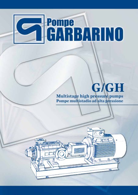
G/GH<br />
<strong>Multistage</strong> <strong>high</strong> <strong>pressure</strong> <strong>pumps</strong><br />
Pompe multistadio ad alta pressione
MULTISTAGE CENTRIFUGAL PUMPS<br />
POMPE CENTRIFUGHE MULTISTADIO<br />
APPLICATIONS<br />
G series multistage centrifugal <strong>pumps</strong> are designed for trouble-free<br />
pumping of clean or slightly dirty liquids without solids<br />
in suspension and used in:<br />
• Steel industry<br />
• Waterworks and water supply plants<br />
• Pressure raising systems<br />
• Water supply system<br />
• Fire fighting system<br />
• Boiler feedwater systems<br />
• High <strong>pressure</strong> washing<br />
• Reverse osmosis<br />
IMPIEGHI<br />
Le pompe centrifughe multistadio della serie G sono idonee al convogliamento<br />
di liquidi puri o leggermente torbidi, senza solidi in sospensione.<br />
Trovano particolare impiego nei seguenti campi:<br />
• impianti siderurgici,<br />
• acquedotti e impianti di approvvigionamento idrico,<br />
• impianti di pressurizzazione,<br />
• impianti antincendio,<br />
• impianti di lavaggio a pressione,<br />
• osmosi inversa,<br />
• alimento caldaia<br />
CONSTRUCTION<br />
The <strong>pumps</strong> are multistage centrifugal with radial split casings.<br />
In all versions the supporting feet on <strong>pressure</strong> side are placed<br />
under the discharge body. For sizes up to 65 the base feet, on<br />
suction side, are placed under the first stage casing, to allow<br />
the rotation of the suction casing in any direction. For bigger<br />
sizes the base feet are placed under the suction body, the rotation<br />
of which is possible only upon request. The impellers<br />
are provided with balancing holes to reduce the axial thrust.<br />
The shaft is supported by grease or oil lubricated bearings.<br />
COSTRUZIONE<br />
Le pompe sono del tipo centrifugo multistadio orizzontale o verticale<br />
con corpi divisi radialmente. In tutte le macchine i piedi di appoggio,<br />
lato premente, sono posti sotto il corpo di mandata. Per le grandezze<br />
sino alla 65, i piedi di appoggio lato aspirazione sono posti sotto il primo<br />
elemento al fine di permettere qualsiasi orientamento della bocca<br />
aspirante. Per le grandezze superiori, i piedi sono invece posti sotto il<br />
corpo aspirante per cui la rotazione del corpo è possibile solo su richiesta.<br />
Le giranti dispongono di fori di bilanciamento della spinta assiale. L’asse<br />
è supportato da cuscinetti a rotolamento lubrificati a grasso o ad olio.<br />
2<br />
G<br />
MAXIMUM OPERATING TEMPERATURE<br />
Up to 180 °C with special arrangements.<br />
TEMPERATURA MASSIMA<br />
DI ESERCIZIO<br />
Fino a 180 °C con esenzioni speciali.<br />
MAXIMUM OPERATING PRESSURE<br />
On suction side: up to 25 bar<br />
On discharge side: up to 64 bar<br />
PRESSIONE MASSIMA DI ESERCIZIO<br />
In aspirazione: fino a 25 bar<br />
In mandata: fino a 64 bar<br />
TECHNICAL FEATURES<br />
Capacity up to 600 m 3 /h<br />
Total head up to 400 m<br />
Speed up to 3500 RPM<br />
Discharge <strong>pressure</strong> up to 64 bar<br />
Flanges: suction side PN 16-25<br />
delivery side PN 40-64<br />
DATI TECNICI<br />
Portata max 600 m 3 /h<br />
Prevalenza max 400 m<br />
Velocità max 3500 rpm<br />
Pressione mandata max 64 bar<br />
Flange: lato aspirazione PN 16-25, lato mandata PN 40-64<br />
VERTICAL MULTISTAGE CENTRIFUGAL PUMPS<br />
“GV” SERIES<br />
Vertical multistage centrifugal <strong>pumps</strong> “GV” series, standard<br />
configuration, with upper ball bearings support and lower<br />
bushing support. Besides the usual applications where <strong>high</strong><br />
<strong>pressure</strong> is required, the vertical configuration is employed in<br />
the shipbuilding industry typically.<br />
VERSIONE VERTICALE (GV)<br />
Versione standard con supportazione tramite cuscinetto a sfere nella<br />
parte superiore e bronzina nella parte inferiore. Oltre all ‘impiego dove<br />
sono richieste alte pressioni, le pompe in esecuzione verticale sono particolarmente<br />
usate in campo navale. Per grandezze non indicate in tabella<br />
consultare l’ Ufficio Tecnico.
MATERIALS<br />
MATERIALI<br />
CaST IRON<br />
GhIsa<br />
STaINleSS STeel, BRONze, SPeCIal allOy<br />
aCCIaIO INOx, brONzO, LeGhe sPeCIaLI<br />
oil lubricated version (125 G)<br />
versione con lubrificazione ad olio (125 G)<br />
bare shaft version (G)<br />
versione ad asse nudo (G)<br />
MAX. wORkING PRESSURE<br />
PRESSIONE MAx. ESERCIzIO<br />
40 bar<br />
64 bar<br />
NOTE: SPECIAL ExECUTIONS ExCEEDING THE AbOVE LIMITS AVAILAbLE ON REqUEST<br />
NOTa: eseCUzIONI sPeCIaLI aL dI FUOrI deI LImITI sOPraesPOsTI reaLIzzaTe sU rIChIesTa<br />
bare shaft version (G)<br />
versione ad asse nudo (G)<br />
vertical version (GV)<br />
versione verticale (GV)<br />
3<br />
OPTION<br />
OIl lUBRICaTION<br />
SPeCIal MeCHaNICal SealS<br />
aTeX CONSTRUCTION<br />
MeCHaNICal Seal WaTeR COOleR<br />
BeaRING VIBRaTION SeNSORS
MULTISTAGE HIGH PRESSURE<br />
CENTRIFUGAL PUMPS<br />
POMPE CENTRIFUGHE MULTISTADIO<br />
AD ALTA PRESSIONE<br />
<strong>Multistage</strong> pump family has been widely tested over the years<br />
in applications with head up to 40 bar. Now, with the<br />
newly developed GH <strong>pumps</strong>, we can achieve head up to 85<br />
bar and capacities up to 500 m3/h.<br />
dopo anni di collaudate applicazioni delle pompe multistadio della<br />
famiglia G su servizi con prevalenze fino a 40 bar, è stato deciso di<br />
aumentare le prestazioni fino ad arrivare a prevalenze di 85 bar con<br />
portate massime di 500 m 3 /h.<br />
APPLICATIONS<br />
These <strong>pumps</strong> are mainly suitable for power generation and<br />
seawater desalination plants, for boiler feed water and reverse<br />
osmosis systems. Their usage can be extended to other<br />
fields such as snowmaking equipment, shipbuilding and offshore<br />
applications, pumping stations, pipeline test work.<br />
IMPIEGHI<br />
Le applicazioni a cui sono destinate queste pompe sono principalmente<br />
il settore power e desalination, rispettivamente per servizi di alimentazione<br />
caldaia ed osmosi inversa. Possono inoltre essere impiegate in<br />
altri settori interessanti quali gli impianti di innevamento artificiale, il<br />
settore navale e offshore per impianti antincendio water mist ed altri.<br />
CONSTRUCTION<br />
The GH design is our latest innovation in multistage technology<br />
on the market, both the hydraulics and the mechanics have<br />
been developed to meet the increasing demand for <strong>high</strong> <strong>pressure</strong><br />
<strong>pumps</strong>.<br />
The GH family consists of 4 sizes (50-65-100-150) and 8 different<br />
hydraulics to grant a solution tailored to customers specifications.<br />
44<br />
GH<br />
The <strong>pumps</strong> are horizontal multistage, radially split; the impellers<br />
are arranged between external bearings.<br />
The main features are:<br />
• Feet cast with suction and delivery casings to grant<br />
stiffness and sturdiness<br />
• UNI– DIN- aNSI -JIS- ISO standard flanges<br />
• The suction flange can be set in three positions<br />
• High efficiency close type impellers; low NPSHr suction<br />
impeller<br />
• Only one wear ring for each impeller, of the replaceable<br />
type<br />
• Oil-sealed external bearings with constant level oiler<br />
• Drum-type device for axial thrust balancing<br />
• Oversized shaft to minimize deflections.<br />
COSTRUZIONE<br />
Le pompe Gh nascono quindi su un progetto completamente nuovo sia<br />
nella parte idraulica sia meccanica, specificatamente sviluppato per le<br />
alte pressioni in gioco e per i servizi previsti.<br />
La gamma delle pompe Gh è costituita da 4 grandezze (50-65-100-<br />
150) con 8 idrauliche diverse per poter garantire una selezione accurata<br />
per ogni richiesta del cliente. Le pompe sono orizzontali del tipo<br />
a stadi con divisione radiale con giranti montate tra cuscinetti esterni.<br />
Le principali caratteristiche costruttive sono le seguenti:<br />
• piedi di fusione con il corpo di aspirazione e mandata per una<br />
maggiore rigidezza e robustezza<br />
• connessioni flangiate secondo standard UNI-dIN-aNsI-JIs-IsO<br />
• flangia di aspirazione ruotabile in tre posizioni<br />
• giranti di tipo chiuso ad alta efficienza con girante di aspirazione a<br />
basso NPsh<br />
• un solo anello di usura per girante, di tipo sostituibile<br />
• cuscinetti esterni a bagno d’olio con oliatore a livello costante<br />
• dispositivo di bilanciamento della spinta assiale a tamburo<br />
• albero sovradimensionato per deflessioni minime.<br />
TECHNICAL FEATURES<br />
Maximum capacity 500 m 3 /h<br />
Maximum head 850 m
Maximum speed 3600 rpm, first critical speed above 5000 rpm<br />
Single balanced mechanical seal<br />
Thrust bearing air or water cooling (option)<br />
GH <strong>pumps</strong> can be supplied in a wide range of materials of<br />
construction. From the basic version which casing is made of<br />
nodular cast iron (GS 500 grade) and impellers in cast iron (G<br />
25 grade) moving to special alloyed steels such as aisi 316<br />
l, Duplex, Superduplex , Hastelloy B and C, Monel, alloy 20.<br />
Fully bronze constructed <strong>pumps</strong> are also available.<br />
DATI TECNICI<br />
Portata max 500 m 3 /h<br />
Prevalenza max 850 m<br />
Velocità massime di 3600 rpm con prima velocità critica sopra i 5000 rpm<br />
Tenuta meccanica semplice o doppia<br />
Possibilità di raffredamento della tenuta e dei cuscinetti<br />
di sicuro interesse è anche la possibilità di fornire le pompe Gh in diverse<br />
metallurgie per ogni specifico problema di compatibilità con il<br />
liquido pompato. La versione base viene prodotta con corpo in ghisa<br />
sferoidale Gs600 e giranti in ghisa G25, ma è possibile avere pompe<br />
in acciai inossidabili speciali quali l’aIsI 316, duplex, superduplex,<br />
hastelloy b e C, monel, alloy 20 ed altro.<br />
kEY FACTORS<br />
• Special design of first stage impeller in order to reduce<br />
bare shaft version (GH)<br />
versione ad asse nudo<br />
5<br />
NPSH required<br />
• No balancing holes on the impellers -> therefore no recirculation<br />
between <strong>high</strong>/low <strong>pressure</strong> chambers -> reduced<br />
losses -> <strong>high</strong> efficiency<br />
• One wear ring for each stage ONly, instead of 2 as per std.<br />
multistage (G <strong>pumps</strong>) -> therefore reduced possibilities of<br />
seizure<br />
• Patented balancing device in order to reduce the recirculation<br />
flow from balancing drum to suction<br />
• Use of special anti-galling material for wear rings<br />
• Special hardening treatment for some rotating parts<br />
• High flexibility due to the possibility to rotate the suction<br />
flange as desired<br />
FATTORI CHIAVE<br />
• Girante del primo stadio progettata in modo da ridurre l’NPsh<br />
• Nessun foro di bilanciamento sulle giranti quindi nessun ricircolo tra<br />
le camere di alta e bassa pressione, perdite ridotte, alta efficienza<br />
• Un solo anello di usura per ogni stadio invece dei due utilizzati per le<br />
pompe multistadio (pompe del tipo G), per ridurre possibili grippaggi<br />
• sistema di bilanciamento brevettato per ridurre il fluido di ricircolo<br />
dal tamburo di bilanciamento all’aspirazione<br />
• Utilizzo di materiali speciali per ridurre il consumo degli anelli di usura<br />
• speciale trattamento superficiale per alcune parti rotanti<br />
• elevata versatilità grazie alla possibilità di rotare la flangia di aspirazione<br />
a richiesta
LONGITUDINAL SECTION (G) - GREASE LUbRICATION VERSION<br />
sezIONe LONGITUdINaLe - VersIONe LUbrIFICaTa a GrassO<br />
LONGITUDINAL SECTION (GH)<br />
sezIONe LONGITUdINaLe<br />
6
Pos Description Descrizione<br />
1130 Suction casing Corpo aspirante<br />
1140 Discharge casing Corpo premente<br />
1150 Stage casing Corpo a mantello<br />
1410 Diffuser diffusore palettato<br />
1413 Diffuser,last stage diffusore ultimo stadio<br />
1510 Casing wear ring anello di usura<br />
1521 Wear ring anello di usura<br />
1660 Delivery casing bush boccola premente<br />
2110 Pump shaft albero della pompa<br />
2200 Impeller Girante<br />
2210 Impeller suction stage Girante di aspirazione<br />
2410 Interstage sleeve bussola interstadi<br />
2450.1 Shaft sleeve Camicia d’albero<br />
2450.2 Shaft sleeve Camicia d’albero<br />
2450.3 Shaft sleeve Camicia d’albero<br />
2460.1 Spacer sleeve bussola distanziatrice<br />
2460.2 Spacer sleeve bussola distanziatrice<br />
2491 locating bearing collar bussola<br />
2510 Spacer ring anello distanziatore<br />
2531 Retaining ring anello d’arresto<br />
3012 Roller bearing Cuscinetto a rulli<br />
3016 Ball bearing Cuscinetto a sfere<br />
VERTICAL VERSION (GV)<br />
VersIONe VerTICaLe<br />
7<br />
Pos Description Descrizione<br />
3160 Motor stool Lanterna motore<br />
3170 Pump stool basamento<br />
3200 Bearing housing supporto<br />
3261 Bearing cover Coperchio supporto<br />
3263 Bearing cover Coperchio supporto<br />
3266 Bearing end cover Coperchio supporto<br />
3270 Oil lubrication cover Coperchio lubrifcazione<br />
3311 Bearing bush boccola<br />
3851 Greaser Ingrassatore<br />
3854 Oil filler plug Tappo per l’olio<br />
3855 Constant level oiler Oliatore livello costante<br />
3856 Spia dell’olio Oil level<br />
4200 Mechanical seal Tenuta meccanica<br />
4210 Seal housing scatola tenuta<br />
4213 Mechanical seal cover Coperchio della tenuta<br />
4260 Molla spring<br />
4300.1 Radial shaft seal anello di tenuta<br />
4300.2 Radial shaft seal anello di tenuta<br />
4610.1 O-ring O-ring<br />
4610.2 O-ring O-ring<br />
4610.3 O-ring O-ring<br />
4610.4 O-ring O-ring<br />
4610.5 O-ring O-ring<br />
4610.6 O-ring O-ring<br />
4610.7 O-ring O-ring<br />
4610.8 O-ring O-ring<br />
4610.9 O-ring O-ring<br />
4610.10 O-ring O-ring<br />
6210 Balance drum Tamburo di equilibrio<br />
6220 anello statico static ring<br />
6230 anello rotante rotating ring<br />
6262 Balance piping Condotto di scarico<br />
6474._ Cylindrical setting pin spina cilindrica<br />
6510.1 Screw plug Tappo filettato<br />
6510.2 Screw plug Tappo filettato<br />
6510.3 Screw plug Tappo filettato<br />
6510.4 Screw plug Tappo filettato<br />
6542.1 lockwasher rosetta per ghiera<br />
6542.2 lockwasher rosetta per ghiera<br />
6571 Housing tie bolt Tirante del corpo<br />
6576._ Screw Vite<br />
6577._ Screw Vite<br />
6579._ Screw Vite<br />
6580 Nut dado<br />
6586.1 locknut Ghiera a tacche<br />
6586.2 locknut Ghiera a tacche<br />
6594 Set screw Grano<br />
6700._ Key Chiavetta<br />
6855 Plain washer rosetta piana
USGPM<br />
HEAD PREVALENZA<br />
HEAD PREVALENZA<br />
400<br />
300<br />
200<br />
100<br />
H mt<br />
50<br />
40<br />
30<br />
20<br />
10<br />
8<br />
7<br />
6<br />
5<br />
USGPM<br />
400<br />
300<br />
200<br />
150<br />
100<br />
H mt<br />
50<br />
40<br />
30<br />
14<br />
12<br />
11<br />
9<br />
8<br />
7<br />
6<br />
5<br />
4<br />
3<br />
2<br />
10<br />
13<br />
25G<br />
14<br />
12<br />
10<br />
9<br />
8<br />
7<br />
6<br />
5<br />
4<br />
3<br />
2<br />
13<br />
11<br />
13<br />
PERFORMANCES (G) PRESTAZIONI<br />
12<br />
11<br />
10<br />
9<br />
8<br />
7<br />
6<br />
5<br />
4<br />
3<br />
2<br />
32G 40G<br />
11<br />
10<br />
8<br />
7<br />
6<br />
5<br />
4<br />
3<br />
2<br />
9<br />
9<br />
8<br />
7<br />
CAPACITY PORTATA Q m 3 /h<br />
10<br />
6<br />
5<br />
4<br />
3<br />
2<br />
50G 65G<br />
9<br />
8<br />
7<br />
6<br />
5<br />
4<br />
3<br />
2<br />
80G<br />
8<br />
7<br />
6<br />
5<br />
4<br />
3<br />
2<br />
100G<br />
8<br />
7<br />
6<br />
5<br />
4<br />
3<br />
2<br />
125Gr<br />
8<br />
7<br />
6<br />
5<br />
4<br />
3<br />
2<br />
125Gn<br />
7<br />
6<br />
5<br />
4<br />
3<br />
2<br />
150G<br />
6<br />
5<br />
4<br />
3<br />
2<br />
200Gr<br />
1450 RPM<br />
10 20 30 40 50 100 200 300 400 500 1000 2000 3000<br />
2 3 4 5 10 20 30 40 50 100 200 300 700<br />
PERFORMANCES (G) PRESTAZIONI<br />
CAPACITY PORTATA Q m3 20<br />
4 5 10 20 30 40 50<br />
/h<br />
6<br />
5<br />
4<br />
3<br />
2<br />
200Gn<br />
20 30 40 50 100 200 300 400 500 1000<br />
14<br />
13<br />
12<br />
11<br />
10<br />
9<br />
8<br />
7<br />
6<br />
5<br />
4<br />
3<br />
2<br />
25G<br />
32G 40G 50G<br />
Operating diagrams at 60 Hz for G <strong>pumps</strong> also available. Contact our main office.<br />
I campi di lavoro delle pompe G sono disponibili anche a 60 hz. Contattare il nostro ufficio.<br />
12<br />
11<br />
10<br />
9<br />
8<br />
7<br />
6<br />
5<br />
4<br />
3<br />
2<br />
10<br />
9<br />
8<br />
7<br />
6<br />
5<br />
4<br />
3<br />
2<br />
8<br />
9<br />
8<br />
7<br />
6<br />
5<br />
4<br />
3<br />
2<br />
65G<br />
7<br />
6<br />
5<br />
4<br />
3<br />
2<br />
6<br />
5<br />
4<br />
3<br />
2<br />
80G<br />
100 200<br />
4<br />
3<br />
2<br />
2900 RPM<br />
100G<br />
1000<br />
500<br />
400<br />
300<br />
200<br />
H feet<br />
100<br />
50<br />
40<br />
30<br />
20<br />
1000<br />
500<br />
400<br />
300<br />
H feet<br />
200<br />
100<br />
90<br />
80<br />
70
HEAD PREVALENZA<br />
HEAD PREVALENZA<br />
USGPM<br />
1000<br />
800<br />
600<br />
500<br />
400<br />
300<br />
200<br />
100<br />
80<br />
60<br />
50<br />
40<br />
30<br />
1400<br />
1000<br />
900<br />
800<br />
700<br />
600<br />
500<br />
400<br />
350<br />
300<br />
250<br />
250<br />
150<br />
100<br />
50<br />
PERFORMANCES (GH) PRESTAZIONI<br />
6 8 10 20 30 40 50 60 80 100 200 300 400 500 600<br />
CAPACITY PORTATA Q m3 /h<br />
PERFORMANCES (GH) PRESTAZIONI<br />
50A<br />
50B<br />
CAPACITY PORTATA<br />
9<br />
65B<br />
65A<br />
Q m 3 /h<br />
100B<br />
100A<br />
150A<br />
150B<br />
2900 RPM<br />
3000<br />
2500<br />
2000<br />
1500<br />
1000<br />
900<br />
800<br />
700<br />
600<br />
500<br />
400<br />
300<br />
H feet<br />
200<br />
150<br />
100<br />
50<br />
3500 RPM
'<br />
b'<br />
D2<br />
D2<br />
g2<br />
PM2<br />
g2<br />
PM2<br />
m3<br />
m3<br />
PUMP DIMENSIONS<br />
DIMENSIONI POMPA<br />
b<br />
m2<br />
m1<br />
v D2<br />
m2<br />
v<br />
m1<br />
pump type 25 G ÷ 65 G<br />
pompa tipo 25 G ÷ 65 G<br />
Key aCCORDING TO UNI 6604<br />
ChIaVeTTa seCONdO UNI 6604<br />
f<br />
f<br />
a g1 h1 h2 g2 b c m3 n1 n2 s v d1 l t u<br />
g1<br />
PM1<br />
g1<br />
PM1<br />
b<br />
D2<br />
l<br />
l<br />
d1<br />
d1<br />
PUMP SHAFT SECTION<br />
SEZ. ALBERO POMPA<br />
PUMP u SHAFT SECTION<br />
SEZ. ALBERO POMPA<br />
u<br />
d1<br />
d1<br />
t<br />
t<br />
b'<br />
D2<br />
g2<br />
PM2<br />
g2<br />
b'<br />
D2<br />
PM2<br />
m3<br />
m3<br />
wEIght (kg)<br />
PESO (kG)<br />
2 stages pump +1 stage<br />
Pompa a 2 stadi +1 stadio<br />
D2<br />
m2 v<br />
PUMP<br />
tyPE<br />
POMPA<br />
TIPO<br />
SUctION flaNgE<br />
bOCCA ASPIR.<br />
DNs<br />
PN16<br />
DElIvEry flaNgE<br />
bOCCA MAND.<br />
DNd<br />
PN40<br />
flaNgES DIMENSIONS<br />
DIMENSIONI FLANGE<br />
UNI 2223 - 2229 - PN 16-40<br />
D D’ b b’ K K1 g g’<br />
b<br />
D1<br />
Øs<br />
n2<br />
b<br />
D1<br />
n1 Øs<br />
n2<br />
non drive n1 end view<br />
vista lato opposto comando<br />
DISCHARGE FLANGE<br />
FL.MANDATA<br />
bEarINg brackEt DraIN<br />
DRENAGGIO SUPPORTO<br />
caSINg PUMP DraIN<br />
DRENAGGIO CORPO POMPA<br />
vacUUM gaUgE<br />
MANOVUOTOMETRO<br />
PrESSUrE gaUgE<br />
MANOMETRO<br />
n° holes<br />
n° fori D2 D1 PM1 PM2<br />
DNs DNd<br />
160 274 132 160 208 45 14 55 250 215 15 320 28 60 30,9 8 70 12 25 G 40 32 150 140 16 18 110 100 18 18 4 4 3/8’’G 1/4’’G 1/4’’G 1/4’’G<br />
180 268 160 180 206 45 14 55 280 245 15 325 28 60 30,9 8 85 16 32 G 50 32 165 140 18 18 125 100 18 18 4 4 3/8’’G 1/4’’G 1/4’’G 1/4’’G<br />
180 291 160 180 213 45 14 55 280 245 15 361 32 80 35,3 10 100 18 40 G 65 40 185 150 18 18 145 110 18 18 4 4 3/8’’G 1/4’’G 1/4’’G 1/4’’G<br />
200 297 160 200 219 45 14 55 280 245 15 378 32 80 35,3 10 125 22 50 G 80 50 200 165 20 20 160 125 18 18 8 4 3/8’’G 1/4’’G 1/4’’G 1/4’’G<br />
240 310 180 240 226 60 16 65 320 280 15 380 32 80 35,3 10 155 29 65 G 100 65 220 185 22 24 180 145 18 18 8 8 3/8’’G 1/4’’G 1/4’’G 1/4’’G<br />
240 310 180 240 226 60 16 65 320 280 15 270 32 80 35,3 10 130 30 80 G 100 80 220 200 22 26 180 160 18 18 8 8 3/8’’G 1/4’’G 1/4’’G 1/4’’G<br />
305 361 215 305 253 80 22 80 425 350 22 311 40 110 43,3 12 200 45 100 G 125 100 250 235 24 26 210 190 18 22 8 8 3/8’’G 3/8’’G 3/8’’G 3/8’’G<br />
400 420 315 400 324 120 25 125 560 455 25 345 45 110 48,8 14 515 105 125 G 150 125 285 270 30 26 240 220 22 25 8 8 3/8’’G 1/2’’G 1/2’’G 1/2’’G<br />
450 490 375 450 387 140 30 150 700 560 33 395 50 110 54,3 16 800 155 150 G 200 150 340 300 30 34 295 250 22 25 12 8 3/8’’G 3/8’’G 3/8’’G 3/8’’G<br />
500 580 415 500 434 150 35 165 750 620 39 480 60 140 64,4 18 1000 200 200 G 250 200 405 375 34 38 355 320 25 30 12 12 3/8’’G 3/8’’G 3/8’’G 3/8’’G<br />
f<br />
f<br />
d1<br />
c<br />
SUCTION FLANGE<br />
g FL.ASPIRAZIONE<br />
g'<br />
DNs<br />
g1<br />
D2<br />
m1<br />
m2 v<br />
K<br />
l<br />
D<br />
d1<br />
PM1<br />
c<br />
g g'<br />
DNs<br />
g1<br />
pump type m1 80 G ÷ 200 G<br />
pompa tipo 80 G ÷ 200 G<br />
SUCTION FLANGE<br />
FL.ASPIRAZIONE<br />
K<br />
l<br />
D<br />
PM1<br />
a<br />
a<br />
DNd<br />
K'<br />
D'<br />
h1 h1 h2 h2<br />
DISCHARGE FLANGE<br />
FL.MANDATA<br />
NUMbEr Of StagES 25 G 32 G 40 G 50 G<br />
PUMP tyPE<br />
POMPA TIPO<br />
65 G 80 G 100 G 125 G 150 G 200 G<br />
NUMERO DI STADI f m1 m2 f m1 m2 f m1 m2 f m1 m2 f m1 m2 f m1 m2 f m1 m2 f m1 m2 f m1 m2 f m1 m2<br />
2 111 142 98 122 142 98 138 145 101 157 153 109 172 191 141 172 302 252 221 381 321 273 523 423 330 630 520 420 750 620<br />
3 168 199 155 179 199 155 200 207 163 222 218 174 252 271 221 252 382 332 316 476 416 401 651 551 470 770 660 590 920 790<br />
4 225 256 212 236 256 212 262 269 225 287 283 239 332 351 301 332 462 412 411 571 511 529 779 679 610 910 800 760 1090 930<br />
5 282 313 269 293 313 269 324 331 287 352 348 304 412 431 381 412 542 492 506 666 606 657 907 807 750 1050 940 930 1260 1130<br />
6 339 370 326 350 370 326 386 393 349 417 413 369 492 511 461 492 622 572 601 781 721 785 1035 935 890 1190 1080 1100 1430 1300<br />
7 396 427 383 407 427 383 448 455 411 482 478 434 572 591 541 572 702 652 696 856 796 913 1163 1063 1030 1330 1220<br />
8 453 484 440 464 484 440 510 517 473 547 543 499 652 671 621 652 782 732 791 951 891 1041 1291 1191<br />
9 510 541 497 521 541 497 572 579 535 612 608 564 732 751 701 732 862 812<br />
10 567 598 554 578 598 554 634 641 597 677 673 629 812 831 781<br />
11 624 655 611 635 655 611 696 703 659 742 738 694<br />
12 681 712 668 692 712 668 758 765 721<br />
13 738 769 725 749 769 725 820 827 783<br />
14 795 826 782 806 826 782<br />
SUCTION FlaNGe POSITION<br />
POsIzIONe deLLa FLaNGIa<br />
dI asPIrazIONe<br />
DRIVe eND VIeW<br />
VIsTa LaTO COmaNdO<br />
STaNDaRD<br />
sTaNdard<br />
OVERALL DIMENSIONS (G)<br />
dImeNsIONI dI INGOmbrO (G)<br />
10<br />
ON ReqUeST<br />
sU rIChIesTa<br />
DNd<br />
K'<br />
D'
v<br />
g1<br />
PM1<br />
b<br />
D2<br />
p f<br />
g3<br />
l<br />
d1<br />
h1<br />
PUMP SHAFT SECTION<br />
SEZ. ALBERO POMPA<br />
u<br />
d1<br />
PUMP TYPE<br />
POMPA TIPO<br />
t<br />
e<br />
r<br />
b'<br />
D2<br />
g2<br />
PM2<br />
h2<br />
m3<br />
q<br />
n. iøt<br />
SUCTION FlaNGe PN16<br />
FLaNGIa asPIrazIONe<br />
UNI PN16 (OPTION UNI PN 25 -aNSI 150)<br />
DISCHaRGe FlaNGe PN64 - PN100<br />
FLaNGIa maNdaTa<br />
UNI PN 100 (OPTION UNI PN 64 - aNSI 600)<br />
f<br />
b<br />
D1<br />
OVERALL DIMENSIONS (GH) Øs<br />
m2 v<br />
n2<br />
dImeNsIONI dI INGOmbrO (Gh)<br />
m1<br />
n1<br />
SUCTION FLANGE<br />
FL.ASPIRAZIONE<br />
d1<br />
c<br />
g g'<br />
DNs<br />
g1<br />
OVERALL DIMENSIONS (GV)<br />
dImeNsIONI dI INGOmbrO (GV)<br />
D2<br />
K<br />
l<br />
D<br />
STANDARD<br />
STANDARD<br />
PUMP tyPE<br />
POMPA TIPO<br />
PUMP DIMENSIONS<br />
DIMENSIONI POMPA<br />
g3 p r e i t q<br />
25 GV 270 166 350 300 4 18 24<br />
32 GV 268 160 350 300 4 18 24<br />
40 GV 295 173 400 350 4 18 24<br />
a<br />
50 GV 301 179 400 350 4 18 24<br />
65 GVPM1 308 192 500 430 4 18 24<br />
80 GV 308 192 400 350 4 18 24<br />
100 GV 365 210 500 430 8 18 30<br />
125 GV 439 240 550x550 450x450 4 18 85<br />
200 GV 590 320 700x700 600X600 4 22 80+10<br />
DNs - suction<br />
ON REQUEST<br />
SU RICHIESTA<br />
DISCHARGE FLANGE<br />
FL.MANDATA<br />
N° STAGES<br />
DNs DNd N° STADI a e f h1 h2 m1 m2 n n1 n2 s d l t u<br />
5 310<br />
65 100 65<br />
10<br />
11<br />
12<br />
2<br />
3<br />
4<br />
5<br />
100 150 100 6 387 455<br />
789<br />
2<br />
3<br />
150 200 150 4<br />
440 529<br />
5 950<br />
6 1060<br />
9876<br />
17<br />
4<br />
355<br />
400<br />
349 405 180 250 32.5 280 220 65 M20 42 110 45 12<br />
445<br />
490<br />
535<br />
580<br />
625<br />
340<br />
405<br />
470<br />
535<br />
225 300<br />
45 330 260 75 M20 48 110 51.5 14<br />
600<br />
665<br />
730<br />
795<br />
620<br />
730<br />
270 380 60 410 330 85 M24 60 140 64 18<br />
840<br />
32<br />
2 150<br />
130<br />
3 215<br />
155<br />
4 280<br />
180<br />
5 345<br />
205<br />
6 410<br />
230<br />
7 475<br />
255<br />
8 540<br />
280<br />
9 605<br />
305<br />
10 670<br />
330<br />
50 80 50 11 735 330 376 160 215 55 27.5 240 190 55 M16 38 80 41 10 1/2" 3/8" 3/8" 355<br />
12 800<br />
380<br />
13 865<br />
405<br />
14 930<br />
430<br />
15 995<br />
455<br />
16 1060<br />
480<br />
1125<br />
505<br />
180<br />
175<br />
255<br />
220<br />
330<br />
265<br />
405<br />
480<br />
555<br />
630<br />
65<br />
1/2" 3/8" 3/8"<br />
705<br />
780<br />
855<br />
930<br />
232<br />
324<br />
416<br />
508<br />
600<br />
90<br />
3/4" 1/2" 1/2"<br />
692<br />
784<br />
876<br />
305<br />
420<br />
535<br />
120<br />
3/4" 1/2" 1/2"<br />
650<br />
765<br />
DNd<br />
K'<br />
D'<br />
h1 h2<br />
Position of suction and delivery flanges<br />
Orientamento bocche aspirazione e mandata<br />
STANDARD<br />
STANDARD<br />
DNd - discharge<br />
ON REQUEST<br />
SU RICHIESTA<br />
DRIVE END VIEW DRIVE END VIEW<br />
11<br />
D1 PM1 PM2<br />
WEIGHT (KG)<br />
PESO (KG)
POMPE GARBARINO S.p.A.<br />
www.pompegarbarino.com<br />
ATEX on request<br />
Headquarters:<br />
Via Marenco, 44 - 15011 Acqui Terme (AL) - Italy - Tel. +39 0144.388671 - Fax +39 0144.55260<br />
E-mail: info@pompegarbarino.it<br />
Milan Branch:<br />
Viale Andrea Doria, 31 - 20124 Milano - Italy - Tel. +39 02.67070037 - Fax +39 02.67070097<br />
E-mail: info.filiale@pompegarbarino.it<br />
G/GH 02 - 11/2011 www.lizea.com