Condizioni di Fornitura - spinelli srl
Condizioni di Fornitura - spinelli srl
Condizioni di Fornitura - spinelli srl

Create successful ePaper yourself
Turn your PDF publications into a flip-book with our unique Google optimized e-Paper software.
lamiere grecate<br />
• produzione lamiere grecate<br />
• pannelli metallici coibentati<br />
• profilati a freddo<br />
• policarbonato<br />
• ferramenta<br />
Spinelli
<strong>Con<strong>di</strong>zioni</strong> <strong>di</strong><br />
<strong>Fornitura</strong><br />
Materiale<br />
• Acciaio zincato con proce<strong>di</strong>mento “sendzimir“ UNI 5753/75<br />
• Acciaio zincato per formatura a freddo: UNI en 10142<br />
• Acciaio zincato strutturale: UNI en 10326<br />
• Acciaio preverniciato sistema base: rivestimento poliestere<br />
sistema super: rivestimento poliestere siliconato<br />
sistema PVDF: rivestimento PVDF Fluoruro <strong>di</strong> Polivinile<br />
• Alluminio naturale e preverniciato UNI 9003/3<br />
• Rame UNI 5649/1<br />
• Acciaio inox<br />
Tolleranze: sullo spessore (secondo norme UNI)<br />
sulla lunghezza ±± 2<br />
Lunghezza massima mt.14<br />
aisi 304-aisi 316 L<br />
Minima mt. 05<br />
Centinatura: possibilità <strong>di</strong> fornitura <strong>di</strong> elementi curvi con raggio a richiesta<br />
Accessori<br />
• gruppi <strong>di</strong> fissaggio completi<br />
• Colmi fustellati e cernierati<br />
• Guarnizioni fustellate ‘in sagoma<br />
• Traslucido grecato in vetroresina<br />
• Policarbonato grecato compatto e alveolare<br />
• Lattoneria a <strong>di</strong>segno<br />
Avvertenze<br />
Le lamiere devono essere immagazzinate in luogo coperto ed asciutto<br />
0 In caso <strong>di</strong> assoluta impossibilità, protette con teloni od altra copertura<br />
adeguata che tuttavia deve essere rimossa nelle ore soleggiate<br />
Per favorire la ventilazione ed evitare la condensa.<br />
Le lamiere zincate temono particolarmente l’umi<strong>di</strong>tà’, pertanto<br />
Sopportano un brevissimo stoccaggio,in cantiere; quin<strong>di</strong> si consiglia<br />
l’impiego imme<strong>di</strong>ato.<br />
Feltro Anticondensa<br />
Sul lato inferiore della lamiera SG 40/1000,e’ possibile applicare durante<br />
la profilatura, un feltro che elimina il fenomeno della condensa,~ grazie<br />
alle proprieta’ fisiche,attenua i rumori causati dagli agenti atmosferici;<br />
Inoltre evita l’aggressione della ruggine a soffitti e strutture metalliche
SG 38/732<br />
-915<br />
Acciaio<br />
Spessore<br />
Peso Kg/m2 Peso Kg/m 1000<br />
1250<br />
J cm4 /m<br />
W cm3 {<br />
/m<br />
Spessore <br />
mm. <br />
0,6<br />
0,7<br />
<br />
0,8 <br />
1,0<br />
Freccia<br />
cm<br />
<br />
<br />
Spessore <br />
mm.<br />
CARATTERISTICHE STATICHE<br />
Distanza tra gli appoggi in metri<br />
Per trasformare i Kg/m 2 in da N/m 2 <strong>di</strong>videre per 1,02.<br />
I valori delle portate in grassetto<br />
prevedono una freccia ≤≤ 1/200 l<br />
Quando non specificato ,<br />
la preverniciatura é sulla faccia A<br />
Carico max uniformemente <strong>di</strong>stribuito<br />
in Kg/m 2 per resistenza<br />
σ = 1450 Kg/cm 2<br />
I carichi più elevati non prevedono<br />
limitazioni <strong>di</strong> freccia.<br />
1,00 1,25 1,50 1,75 2,00 2,25 2,50 2,75 3,00 3,25 3,50 3,75 4,00<br />
566 364 253 186 142 112 92 75 62 54 46 40 36<br />
142 100 73 55 42 33 - - -<br />
664 425 296 216 166 131 106 88 74 63 54 47 41<br />
166 116 85 64 49 39 - - -<br />
762 487 336 248 190 150 122 101 85 72 62 54 48<br />
189 133 96 73 56 46 36 - -<br />
952 610 424 311 238 188 153 126 106 90 78 68 60<br />
236 166 121 91 72 56 44 36 -<br />
0,25 0,39 0,56 0,77 1,00 1,13 1,25 1,38 1,50 1,63 1,75 1,88 2,00<br />
Distanza tra gli appoggi in metri<br />
0,6 0,7 0,8 1,0<br />
6,42 7,49 8,57 10,72<br />
4,71 5,49 6,28 7,85<br />
5,88 6,89 7,85 9,81<br />
14,1 16,42 18,76 23,38<br />
4,9 5,72 6,56 8,82<br />
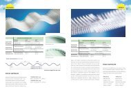
Lamiere grecate<br />
per coperture e pareti<br />
1,00 1,25 1,50 1,75 2,00 2,25 2,50 2,75 3,00 3,25 3,50 3,75 4,00<br />
0,6<br />
712 455 316 232 178 140 114 94<br />
92<br />
79<br />
70<br />
67<br />
55<br />
58<br />
44<br />
51<br />
36<br />
44<br />
-<br />
0,7<br />
829 531 369 273 207 164 132 110<br />
106<br />
92<br />
82<br />
79<br />
64<br />
68<br />
51<br />
59<br />
42<br />
53<br />
34<br />
0,8<br />
952 609 422 312 238 188 152 126<br />
122<br />
106<br />
93<br />
90<br />
73<br />
78<br />
59<br />
68<br />
48<br />
59<br />
39<br />
1,0 1192 763 530 389 298 235 192 158<br />
151<br />
132<br />
116<br />
112<br />
92<br />
97<br />
73<br />
85<br />
60<br />
74<br />
49<br />
Freccia<br />
cm 0,19 0,29 0,42 0,58 0,75 0,95 1,17 1,38 1,50 1,63 1,75 1,88 2,00<br />
A<br />
B<br />
A<br />
B<br />
Lamiere grecate<br />
per coperture e pareti<br />
I valori delle portate in grassetto<br />
prevedono una freccia ≤≤ 1/200 l<br />
Quando non specificato ,<br />
la preverniciatura é sulla faccia A<br />
Carico max uniformemente <strong>di</strong>stribuito<br />
in Kg/m 2 per resistenza<br />
σ = 1450 Kg/cm 2<br />
Spessore <br />
mm. <br />
0,6<br />
0,7<br />
<br />
0,8 <br />
1,0<br />
Freccia<br />
cm<br />
<br />
<br />
Spessore <br />
mm.<br />
I carichi più elevati non prevedono<br />
limitazioni <strong>di</strong> freccia.<br />
Distanza tra gli appoggi in metri<br />
1,00 1,25 1,50 1,75 2,00 2,25 2,50 2,75 3,00 3,25 3,50 3,75 4,00<br />
480 307 213 157 120 95 77 64 53 45 39 34 -<br />
141 94 66 48 36 - - - - -<br />
573 367 255 187 143 113 92 76 64 54 47 41 36<br />
170 114 80 58 44 34 - - - -<br />
668 428 297 218 167 132 107 88 74 63 55 48 42<br />
205 137 97 70 53 41 32 - - -<br />
860 550 382 281 215 170 138 114 96 81 70 61 54<br />
274 183 129 94 71 54 43 34 - -<br />
0,31 0,49 0,71 0,88 1,00 1,13 1,25 1,38 1,50 1,63 1,75 1,88 2,00<br />
Distanza tra gli appoggi in metri<br />
Spessore<br />
Peso Kg/m2 Peso Kg/m 1000<br />
1250<br />
J cm4 /m<br />
W cm3 {<br />
/m<br />
SG 38/732<br />
-915<br />
Acciaio<br />
1,00 1,25 1,50 1,75 2,00 2,25 2,50 2,75 3,00 3,25 3,50 3,75 4,00<br />
0,6<br />
600 384 267 196 150 119<br />
111<br />
96<br />
81<br />
79<br />
61<br />
67<br />
47<br />
57<br />
37<br />
49<br />
-<br />
43<br />
-<br />
38<br />
-<br />
0,7<br />
716 458 318 234 179 141<br />
133<br />
115<br />
97<br />
95<br />
73<br />
80<br />
56<br />
68<br />
44<br />
58<br />
35<br />
51<br />
-<br />
45<br />
-<br />
0,8<br />
835 535 371 273 209 165<br />
161<br />
134<br />
117<br />
110<br />
88<br />
93<br />
68<br />
79<br />
53<br />
68<br />
43<br />
59<br />
35<br />
52<br />
-<br />
1,0 1074 688 478 351 269 212 172<br />
157<br />
142<br />
118<br />
119<br />
91<br />
102<br />
71<br />
88<br />
57<br />
76<br />
46<br />
67<br />
38<br />
Freccia<br />
cm 0,24 0,37 0,53 0,72 0,94 1,13 1,25 1,38 1,50 1,63 1,75 1,88 2,00<br />
B<br />
A<br />
CARATTERISTICHE STATICHE<br />
0,6 0,7 0,8 1,0<br />
6,42 7,49 8,57 10,72<br />
4,71 5,49 6,28 7,85<br />
5,88 6,89 7,85 9,81<br />
9,37 11,3 13,64 18,2<br />
4,14 4,94 5,76 7,41<br />
Per trasformare i Kg/m 2 in da N/m 2 <strong>di</strong>videre per 1,02.<br />
B<br />
A
SG 40/1000<br />
Acciaio<br />
Spessore<br />
Peso Kg/m 2<br />
J cm 4 /m<br />
W cm 3 /m<br />
Spessore <br />
mm. <br />
0,6<br />
0,7<br />
0,8<br />
1,0<br />
<br />
<br />
Freccia<br />
cm<br />
<br />
<br />
Spessore <br />
mm.<br />
A<br />
CARATTERISTICHE STATICHE<br />
Distanza tra gli appoggi in metri<br />
B<br />
0.6 0.7 0.8 1.0<br />
5.89 6.87 7.85 9.81<br />
15.40 17.96 20.53 25.66<br />
5.06 5.90 6.74 8.43<br />
Carico massimo uniformemetne <strong>di</strong>stribuito in kg/mq<br />
I valori delle portate in grassetto<br />
prevedono una freccia ≤≤ 1/200 l<br />
Quando non specificato ,<br />
la preverniciatura é sulla faccia A<br />
Carico max uniformemente <strong>di</strong>stribuito<br />
in Kg/m 2 per resistenza<br />
σ = 1450 Kg/cm 2<br />
I carichi più elevati non prevedono<br />
limitazioni <strong>di</strong> freccia.<br />
1,00 1,25 1,50 1,75 2,00 2,25 2,50 2,75 3,00 3,25 3,50 3,75 4,00<br />
585 376 260 190 146 115 92 77 66 55<br />
110 80 60 46 36<br />
682 437 302 223 172 134 100 89 75 64 55<br />
128 93 69 54 42 33<br />
782 500 347 256 196 154 125 103 87 73 64 56<br />
147 107 80 62 48 39 31<br />
976 626 432 318 244 192 155 129 108 93 79 68 61<br />
186 133 100 76 61 48 39 32<br />
0.23 0.36 0.52 0.71 0.94 1.12 1.25 1,37 1.50 1.62 1.75 1.87 2.00<br />
1,00 1,25 1,50 1,75 2,00 2,25 2,50 2,75 3,00 3,25 3,50 3,75 4,00<br />
0,6<br />
0,7<br />
0,8<br />
1,0<br />
Freccia<br />
cm<br />
Carico massimo uniformemetne <strong>di</strong>stribuito in kg/mq<br />
Distanza tra gli appoggi in metri<br />
Lamiere grecate<br />
per coperture e pareti<br />
732 468 325 240 183 145 117 96 81 68 59<br />
78 61 48<br />
855 548 380 279 214 168 136 113 94 80 72 60<br />
91 71 55 46<br />
978 625 434 319 242 192 156 129 108 93 79 69 61<br />
103 81 65 52 43<br />
1222 782 542 398 305 242 195 162 135 115 99 87 76<br />
129 102 82 66 54<br />
0.17 0.27 0.39 0.53 0.70 0.88 1.09 1.31 1 .50 1.62 1.75 1.87 2.00<br />
lamiere grecate<br />
per coperture e pareti<br />
I valori delle portate in grassetto<br />
prevedono una freccia ≤≤ 1/200 l<br />
Quando non specificato ,<br />
la preverniciatura é sulla faccia A<br />
Spessore <br />
mm. <br />
<br />
<br />
Freccia<br />
cm<br />
<br />
<br />
Per trasformare i Kg/m 2 in da N/m 2 <strong>di</strong>videre per 1,02. Per trasformare i Kg/m 2 in da N/m 2 <strong>di</strong>videre per 1,02.<br />
0,6<br />
0,7<br />
0,8<br />
1,0<br />
Spessore <br />
mm.<br />
Distanza tra gli appoggi in metri<br />
Spessore<br />
Peso Kg/m 2<br />
J cm 4 /m<br />
W cm 3 /m<br />
CARATTERISTICHE STATICHE<br />
0,6 0,7 0,8 1,0<br />
5.89 6.87 7.85 9.81<br />
9.05 11.16 13.37 17,07<br />
4.15 4,79 5.77 7.43<br />
1,00 1,25 1,50 1,75 2,00 2,25 2,50 2,75 3,00 3,25 3,50 3,75 4,00<br />
482 307 213 156 120 96 76 63<br />
138 92 66 46 35<br />
576 368 256 187 143 113 91 76 63<br />
170 113 80 53 44 33<br />
668 428 296 218 167 131 107 87 74 62 53<br />
204 136 95 69 52 40 31 25<br />
862 552 382 282 214 170 137 112 95 81 69 61 53<br />
276 186 130 96 70 56 43 34 27 22<br />
0.32 0.50 0.72 0.87 1.00 1.12 1.25 1.37 1.50 1.62 1.75 1.87 2.00<br />
1,00 1,25 1,50 1,75 2,00 2,25 2,50 2,75 3,00 3,25 3,50 3,75 4,00<br />
0,6<br />
0,7<br />
0,8<br />
1,0<br />
Freccia<br />
cm<br />
B<br />
A<br />
Carico max uniformemente <strong>di</strong>stribuito<br />
in Kg/m 2 per resistenza<br />
σ = 1450 Kg/cm 2<br />
I carichi più elevati non prevedono<br />
limitazioni <strong>di</strong> freccia.<br />
Distanza tra gli appoggi in metri<br />
602 384 268 195 152 118 95 79 67<br />
108 78 58 45<br />
719 460 319 234 179 141 114 94 79 67 58<br />
133 97 72 56 42 35<br />
838 535 372 272 208 165 133 110 92 79 67 59<br />
160 118 88 67 52 42 34<br />
1077 688 478 352 268 212 172 142 119 102 87 76 66<br />
158 118 90 71 57 46 38<br />
0.24 0.38 0.54 0.74 0.97 1.12 1.25 1.37 1.50 1.62 1.75 1.87 2.00<br />
SG 40/1000<br />
Acciaio
SG 40/1000<br />
Alluminio<br />
I valori delle portate in grassetto<br />
prevedono una freccia ≤≤ 1/200 l<br />
Quando non specificato ,<br />
la preverniciatura é sulla faccia A<br />
I carichi più elevati non prevedono<br />
limitazioni <strong>di</strong> freccia.<br />
A<br />
B<br />
<br />
<br />
<br />
<br />
<br />
<br />
<br />
<br />
Spessore<br />
mm.<br />
Per trasformare i Kg/m 2 in da N/m 2 <strong>di</strong>videre per 1,02.<br />
0,6<br />
0,7<br />
0,8<br />
1,0<br />
Freccia<br />
cm<br />
Spessore<br />
mm.<br />
0,6<br />
0,7<br />
0,8<br />
1,0<br />
Freccia<br />
cm<br />
Spessore<br />
Peso Kg/m2 J cm4 /m<br />
W cm3 /m<br />
Carico massimo uniformemetne <strong>di</strong>stribuito in kg/mq<br />
Distanza tra gli appoggi in<br />
CARATTERISTICHE STATICHE<br />
1,00 1,25 1,50 1,75 2,00 2,25 2,50<br />
283 181 128 92 70 56 45<br />
122 78 52 36 26<br />
332 212 148 108 83 65 52<br />
142 90 60 42 30<br />
378 241 168 123 92 74 60<br />
162 102 68 48 35<br />
472 302 210 152 118 93 75<br />
202 128 88 60 44<br />
0.34 0.54 0.75 0.88 1.00 1.12 1.25<br />
Carico massimo uniformemetne <strong>di</strong>stribuito in kg/mq<br />
Distanza tra gli appoggi in metri<br />
1,00 1,25 1,50 1,75 2,00 2,25 2,50<br />
354 228 158 115 88 68 58<br />
85 60 44<br />
412 262 193 132 102 81 65<br />
100 70 51<br />
472 302 212 154 118 92 75<br />
114 80 58<br />
592 378 262 192 148 116 94<br />
143 100 72<br />
0.26 0.40 0.58 0.79 1.00 1.13 1.25<br />
Lamiere grecate<br />
per coperture e pareti<br />
0.6 0.7 0.8 1.0<br />
2.02 2.36 2.7 3.37<br />
15.40 17.96 20.53 25.66<br />
5.06 5.90 6.74 8.43<br />
Spessore<br />
Peso Kg/m 2<br />
Peso Kg/m 1000<br />
J cm 4 /m<br />
W cm 3 /m<br />
spessore<br />
mm<br />
0,6<br />
0,7<br />
0,8<br />
1,0<br />
1,2<br />
1,5<br />
Spessore<br />
<br />
mm. <br />
0,6<br />
0,7<br />
0,8<br />
1,0<br />
<br />
<br />
1,2<br />
<br />
1,5<br />
Freccia<br />
cm<br />
{<br />
1250<br />
CARATTERISTICHE STATICHE<br />
0,6 0,7 0,8 1,0 1,2 1,5<br />
7,85 9,16 10,47 13,08 15,7 19,62<br />
4,71 5,49 6,28 7,85 9,42 11,77<br />
5,88 6,86 7,85 9,81 11,77 14,71<br />
42,19 51,28 60,67 79,92 98,39 122,4<br />
12,2 15,15 18,28 25,01 32,19 42,67<br />
Distanza tra gli appoggi in metri<br />
1,00 1,25 1,50 1,75 2,00 2,25 2,50 2,75 3,00 3,25 3,50 3,75 4,00 4,25 4,50 4,75 5,00<br />
1413 906 629 461 354 280 226 187 157 134 116 101 88 78 72 62 57<br />
218 164 126 99 79 65 53 44 37 32 -<br />
1757 1124 781 574 439 347 281 232 195 166 142 125 110 97 87 78 70<br />
265 198 153 120 96 78 65 54 45 39 33<br />
2120 1357 942 692 531 419 339 280 236 202 173 151 133 117 105 94 85<br />
313 235 181 143 114 93 76 64 54 46 39<br />
2901 1857 1289 947 725 573 464 384 322 275 237 206 181 161 143 129 116<br />
566 412 310 239 188 150 122 101 84 71 60 52<br />
3733 2390 1660 1218 934 738 597 494 415 354 305 266 233 207 184 165 149<br />
698 508 382 294 232 185 152 124 103 87 72 63<br />
4950 3168 2200 1616 1237 978 792 655 550 469 402 352 309 274 244 219 198<br />
868 632 475 368 288 230 187 154 129 107 91 79<br />
0,22 0,33 0,49 0,66 0,86 1,13 1,25 1,38 1,50 1,63 1,75 1,88 2,00 2,13 2,25 2,38 2,50<br />
Distanza tra gli appoggi in metri<br />
B<br />
A<br />
I valori delle portate in grassetto<br />
prevedono una freccia ≤≤ 1/200 l<br />
Quando non specificato ,<br />
la preverniciatura é sulla faccia A<br />
Carico max uniformemente <strong>di</strong>stribuito<br />
in Kg/m 2 per resistenza<br />
σ = 1450 Kg/cm 2<br />
C a l C o l o s e C o n d o C n R 1 0 0 2 2 C a R a t t e R i s t i C h e s t a t i C h e<br />
SG 55/600<br />
Liscia<br />
Lamiere grecate<br />
per solai<br />
I carichi più elevati non prevedono<br />
limitazioni <strong>di</strong> freccia.<br />
LEMBO SUP. COMPRESSO LEMBO INF. COMPRESSO<br />
y j We Wi J FR y J Wi We<br />
4 3 3 4 4 3 3<br />
cm cm/m cm/m cm/m cm/m cm cm/m cm/m cm/m<br />
compresso teso compresso teso<br />
3,10 37,22 12,00 15,51 39,08 3,13 37,66 12,03 15,89<br />
3,045 45,33 14.88 18,47 47,66 3,075 45,85 14,91 18,91<br />
2,994 53,76 17,95 21,45 56,53 3,025 54,36 17,97 21,96<br />
2,905 71,37 24,57 27,51 74,93 2,938 72,12 24,55 28,15<br />
2,832 89,73 31,68 33,63 93,84 2,867 90,58 31,60 34,40<br />
2,748 118,02 42,95 42,88 119,57 2,786 118,94 42,69 43,83<br />
Spessore <br />
mm. 1,00 1,25 1,50 1,75 2,00 2,25 2,50 2,75 3,00 3,25 3,50 3,75 4,00 4,25 4,50 4,75 5,00<br />
0,6<br />
1768 1132 788 578 442 349 283 235 197 167<br />
162<br />
143<br />
132<br />
126<br />
108<br />
111<br />
89<br />
98<br />
73<br />
87<br />
63<br />
78<br />
52<br />
72<br />
45<br />
0,7<br />
2197 1406 976 717 549 435 351 290 244 208<br />
201<br />
179<br />
161<br />
156<br />
133<br />
137<br />
108<br />
122<br />
90<br />
108<br />
76<br />
97<br />
64<br />
88<br />
55<br />
0,8<br />
2651 1696 1178 868 663 524 424 350 295 251<br />
238<br />
216<br />
190<br />
188<br />
155<br />
166<br />
127<br />
147<br />
106<br />
131<br />
89<br />
117<br />
76<br />
106<br />
65<br />
1,0<br />
3628 2321 1612 1184 905 716 580 480 402<br />
398<br />
343<br />
312<br />
296<br />
251<br />
258<br />
204<br />
227<br />
168<br />
201<br />
140<br />
179<br />
118<br />
161<br />
100<br />
144<br />
86<br />
1,2<br />
4668 2987 2075 1525 1167 922 745 617 519<br />
490<br />
442<br />
385<br />
383<br />
308<br />
332<br />
253<br />
292<br />
207<br />
258<br />
172<br />
230<br />
145<br />
207<br />
123<br />
186<br />
106<br />
1,5<br />
6188 3960 2750 2020 1545 1222 990 818<br />
791<br />
687<br />
612<br />
586<br />
479<br />
505<br />
383<br />
440<br />
313<br />
387<br />
257<br />
343<br />
214<br />
306<br />
181<br />
275<br />
154<br />
247<br />
132<br />
Freccia<br />
cm<br />
0,16 0,25 0,36 0,49 0,64 0,81 1,00 1,21 1,50 1,63 1,75 1,88 2,00 2,13 2,25 2,38 2,50<br />
Tutti i dati riportati in questa scheda sono stati eseguiti teoricamente ad uso esclusivo<br />
del progettista al quale l’acquirente deve sottoporli per l’approvazione.<br />
Per trasformare i Kg/m 2 in da N/m 2 <strong>di</strong>videre per 1,02.
SG 55/600<br />
Lamiere grecate<br />
con soletta collaborante<br />
10 11<br />
Collaborante<br />
LUCE MASSIMA IN METRI PER SOLAI<br />
H soletta spessore sovraccarico <strong>di</strong> esercizio utile uniformemente <strong>di</strong>stribuito k/mq<br />
cm mm 150 200 250 300 350 400 450 500 550 600 700 800 1000 1200 1500 2000<br />
9<br />
peso<br />
165<br />
kg/mq<br />
0,7<br />
0,8<br />
1.0<br />
1,2<br />
1,5<br />
3,21<br />
3,70<br />
3,45<br />
3,95<br />
3,84<br />
4,41<br />
4,23<br />
4,81<br />
4,68<br />
5,35<br />
3,08<br />
3,49<br />
3,29<br />
3,72<br />
3,68<br />
4,14<br />
4,02<br />
4,53<br />
4,48<br />
5,03<br />
2,96<br />
3,31<br />
3,16<br />
3,52<br />
3,52<br />
3,94<br />
3,85<br />
4,28<br />
4,28<br />
4,78<br />
2,85<br />
3,16<br />
3,02<br />
3,36<br />
3,39<br />
3,75<br />
3,69<br />
4,08<br />
4,11<br />
4,53<br />
2,75<br />
3,01<br />
2,92<br />
3,22<br />
3,27<br />
3,58<br />
3,56<br />
3,90<br />
3,98<br />
4,33<br />
2,66<br />
2,91<br />
2,82<br />
3,09<br />
3,14<br />
3,44<br />
3,43<br />
3,74<br />
3,82<br />
4,15<br />
2,58<br />
2,80<br />
2,75<br />
2,98<br />
3,06<br />
3,31<br />
3,33<br />
3,60<br />
3,70<br />
3,99<br />
2,51<br />
2,71<br />
2,67<br />
2,88<br />
2,97<br />
3,20<br />
3,23<br />
3,48<br />
3,58<br />
3,85<br />
2,44<br />
2,62<br />
2,59<br />
2,79<br />
2,89<br />
3,10<br />
3,13<br />
3,37<br />
3,48<br />
3,73<br />
2,37<br />
2,54<br />
2,52<br />
2,70<br />
2,81<br />
3,00<br />
3,06<br />
3,26<br />
3,38<br />
3,43<br />
2,26<br />
2,41<br />
2,42<br />
2,56<br />
2,67<br />
2,84<br />
2,91<br />
2,93<br />
2,94<br />
2,94<br />
2,16<br />
2,29<br />
2,30<br />
2,43<br />
2,54<br />
2,58<br />
2,58<br />
2,58<br />
2,58<br />
2,58<br />
2,01<br />
2,06<br />
2,06<br />
2,06<br />
2,06<br />
2,06<br />
2,06<br />
2,06<br />
2,06<br />
2,08<br />
1,72<br />
1,72<br />
1,72<br />
1,72<br />
1,72<br />
1,72<br />
1,73<br />
1,72<br />
1,72<br />
1,72<br />
1,37<br />
1,37<br />
1,37<br />
1,37<br />
1,37<br />
1,37<br />
1,37<br />
1,37<br />
1,37<br />
1,37<br />
1,03<br />
1,03<br />
1,03<br />
1,03<br />
1,03<br />
1,03<br />
1,03<br />
1,03<br />
1,03<br />
1,03<br />
10<br />
peso<br />
190<br />
kg/mq<br />
0,7<br />
0,8<br />
1,0<br />
1,2<br />
1,5<br />
3,12<br />
3,63<br />
3,35<br />
3,88<br />
3,74<br />
4,33<br />
4,12<br />
4,76<br />
4,56<br />
5,27<br />
3,01<br />
3,45<br />
3,22<br />
3,69<br />
3,60<br />
4,12<br />
3,95<br />
4,52<br />
4,39<br />
5,02<br />
2,91<br />
3,31<br />
3,11<br />
3,55<br />
3,48<br />
3,94<br />
3,82<br />
4,33<br />
4,22<br />
4,78<br />
2,82<br />
3,18<br />
3,02<br />
3,39<br />
3,39<br />
3,78<br />
3,70<br />
4,15<br />
4,09<br />
4,58<br />
2,75<br />
3,06<br />
2,95<br />
3,27<br />
3,26<br />
3,64<br />
3,59<br />
4,00<br />
3,96<br />
4,40<br />
2,66<br />
2,96<br />
2,84<br />
3,15<br />
3,17<br />
3,51<br />
3,48<br />
3,86<br />
3,84<br />
4,22<br />
2,59<br />
2,86<br />
2,77<br />
3,05<br />
3,09<br />
3,39<br />
3,39<br />
3,73<br />
3,74<br />
4,10<br />
2,55<br />
2,78<br />
2,70<br />
2,96<br />
3,01<br />
3,29<br />
3,32<br />
3,62<br />
3,62<br />
3,97<br />
2,47<br />
2,70<br />
2,63<br />
2,87<br />
2,93<br />
3,19<br />
3,22<br />
3,52<br />
3,55<br />
3,85<br />
2,41<br />
2,62<br />
2,55<br />
2,80<br />
2,87<br />
3,11<br />
3,15<br />
3,42<br />
3,42<br />
3,72<br />
2,31<br />
2,50<br />
2,47<br />
2,66<br />
2,74<br />
2,95<br />
3,01<br />
3,22<br />
3,23<br />
3,23<br />
2,22<br />
2,38<br />
2,37<br />
2,54<br />
2,63<br />
2,82<br />
2,83<br />
2,83<br />
2,83<br />
2,82<br />
2,05<br />
2,20<br />
2,21<br />
2,25<br />
2,26<br />
2,26<br />
2,26<br />
2,26<br />
2,26<br />
2,26<br />
1,88<br />
1,88<br />
1,88<br />
1,88<br />
1,88<br />
1,88<br />
1,88<br />
1,88<br />
1,88<br />
1,88<br />
1,51<br />
1,51<br />
1,51<br />
1,51<br />
1,51<br />
1,51<br />
1,51<br />
1,51<br />
1,51<br />
1,51<br />
1,13<br />
1,13<br />
1,13<br />
1,13<br />
1,13<br />
1,13<br />
1,13<br />
1,13<br />
1,13<br />
1,13<br />
11<br />
peso<br />
215<br />
kg/mq<br />
0,7<br />
0,8<br />
1.0<br />
1,2<br />
3,02<br />
3,52<br />
3,23<br />
3,78<br />
3,62<br />
4,23<br />
3,95<br />
4,63<br />
2,93<br />
3,40<br />
3,14<br />
3,64<br />
3,51<br />
4,05<br />
3,84<br />
4,45<br />
2,85<br />
3,28<br />
3,05<br />
3,50<br />
3,41<br />
3,91<br />
3,75<br />
4,27<br />
2,78<br />
3,17<br />
2,98<br />
3,38<br />
3,32<br />
3,75<br />
3,65<br />
4,12<br />
2,72<br />
3,07<br />
2,90<br />
3,28<br />
3,23<br />
3,65<br />
3,53<br />
3,98<br />
2,62<br />
2,98<br />
2,83<br />
3,18<br />
3,15<br />
3,55<br />
3,45<br />
3,86<br />
2,59<br />
2,89<br />
2,78<br />
3,09<br />
3,08<br />
3,45<br />
3,35<br />
3,75<br />
2,52<br />
2,82<br />
2,70<br />
3,00<br />
3,01<br />
3,35<br />
3,29<br />
3,65<br />
2,48<br />
2,72<br />
2,65<br />
2,93<br />
2,95<br />
3,26<br />
3,22<br />
3,55<br />
2,42<br />
2,68<br />
2,59<br />
2,88<br />
2,89<br />
3,18<br />
3,15<br />
3,46<br />
2,32<br />
2,56<br />
2,50<br />
2,73<br />
2,78<br />
3,03<br />
3,03<br />
3,30<br />
2,26<br />
2,46<br />
2,41<br />
2,62<br />
2,68<br />
2,91<br />
2,92<br />
3,15<br />
2,12<br />
2,28<br />
2,28<br />
2,43<br />
2,50<br />
2,50<br />
2,50<br />
2,50<br />
2,01<br />
2,08<br />
2,08<br />
2,08<br />
2,08<br />
2,08<br />
2,08<br />
2,08<br />
1,67<br />
1,67<br />
1,67<br />
1,67<br />
1,67<br />
1,67<br />
1,67<br />
1,67<br />
1,25<br />
1,25<br />
1,25<br />
1,25<br />
1,25<br />
1,25<br />
1,25<br />
1,25<br />
1,5<br />
4,42 4,28 4,15 4,04 3,93 3,83 3,76 3,66 3,56 3,50 3,36 3,13 2,50 2,06 1,67 1,25<br />
5,15 4,95 4,76 4,56 4,43 4,29 4,16 4,04 3,93 3,84 3,56 3,13 2,50 2,08 1,67 1,25<br />
0,7<br />
2,91 2,86 2,76 2,72 2,66 2,61 2,56 2,51 2,47 2,43 2,36 2,26 2,15 2,05 1,81 1,36<br />
12<br />
3,44 3,33 3,23 3,14 3,06 2,97 2,90 2,83 2,76 2,71 2,60 2,50 2,34 2,21 1,81 1,35<br />
0,8 3,12 3,05 2,98 2,91 2,85 2,79 2,74 2,67 2,64 2,57 2,51 2,43 2,30 2,18 1,81 1,36<br />
peso<br />
3,68 3,58 3,45 3,37 3,27 3,17 3,10 3,02 2,95 2,89 2,77 2,67 2,47 2,27 1,81 1,37<br />
1.0 3,52 3,42 3,33 3,26 3,19 3,12 3,06 3,02 2,95 2,89 2,82 2,71 2,56 2,27 1,81 1,36<br />
240<br />
4,12 3,99 3,86 3,72 3,64 3,52 3,45 3,37 3,29 3,22 3,09 2,97 2,72 2,27 1,81 1,36<br />
1,2 3,82 3,73 3,62 3,56 3,48 3,42 3,42 3,27 3,22 3,16 3,05 2,95 2,72 2,27 1,81 1,36<br />
kg/mq 4,52 4,36 4,22 4,09 3,97 3,87 3,77 3,67 3,59 3,52 3,36 3,24 2,72 2,27 1,81 1,36<br />
1,5 4,28 4,17 4,06 3,97 3,88 3,82 3,72 3,62 3,57 3,51 3,39 3,28 2,72 2,27 1,81 1,36<br />
5,02 4,86 4,72 4,55 4,42 4,31 4,19 4,08 3,98 3,89 3,73 3,40 2,72 2,27 1,81 1,36<br />
con<strong>di</strong>zioni<br />
<strong>di</strong> appoggio<br />
Tutti i dati riportati in questa scheda sono stati eseguiti<br />
teoricamente ad uso esclusivo del progettista al quale<br />
l’acquirente deve sottoporli per l’approvazione.<br />
Per trasformare i Kg/m 2 in da N/m 2 <strong>di</strong>videre per 1,02.<br />
Lamiere grecate<br />
per solai<br />
spessore<br />
mm<br />
0,7<br />
0,8<br />
1<br />
1,2<br />
1,5<br />
peso<br />
N O R M A T I V A D I R I F E R I M E N T O C N R 1 0 0 2 2 A C C I A I O S 2 8 0 G D U N I E N 1 0 3 2 6<br />
A<br />
B<br />
SG 75/800<br />
Liscia<br />
kg/mq 4 3 3 4 4 3 3<br />
mm cm/ml cm/ml cm/ml cm/ml cm cm/ml cm/ml cm/ml<br />
8,58<br />
9,81<br />
12,26<br />
14,71<br />
18,39<br />
LEMBO SUP. COMPRESSO LEMBO INF. COMPRESSO<br />
C n R 1 0 0 2 2<br />
y J We Wi J FR y J We Wi<br />
36,53 72,57 19,86 18,87 91,07 51,41 82,62 35,03 16,07<br />
36,62 83,00 22,68 21,64 107,58 50,82 98,44 40,71 19,37<br />
41,35 90,55 21,9 26,91 113,57 49,79 131,71 52,24 26,45<br />
39,74 121,36 30,54 34,42 149,83 48,76 175,38 66,82 35,97<br />
38,30 154,29 40,29 42,04 188,02 47,98 220,15 81,46 45,89<br />
Per trasformare i Kg/m 2 in da N/m 2 <strong>di</strong>videre per 1,02.
<strong>di</strong>s.<br />
SG 75/800<br />
12 13<br />
Liscia<br />
Tabelle <strong>di</strong> portata ( da N/mq ≅ kg/mq )<br />
Profilo SG 75/800 Irrigi<strong>di</strong>menti superiori<br />
Acciaio S 280 GD UNI EN 10326<br />
Normativa <strong>di</strong> riferimento CNR. 10022<br />
Spessore<br />
mm.<br />
0,7<br />
0,8<br />
1,0*<br />
1,25*<br />
1,5*<br />
Una campata Portata utile daN/mq<br />
Due campate Portata utile da kg/mq<br />
Acciaio S 280 GD UNI EN 10326<br />
Normativa <strong>di</strong> riferimento CNR. 10022<br />
LUCE ( m )<br />
LUCE ( m )<br />
Il calcolo della freccia è stato condotto considerando un carico <strong>di</strong> neve ridotto al 70% come da D.M. gennaio 1996<br />
Distanza tra gli appoggi in metri<br />
Spessore<br />
mm. 1,0 1,2 1,4 1,6 1,8 2,0 2,2 2,4 2,6 2,8 3,0 3,20 3,40 3,60 3,8 4,0 4,2 4,4 4,6 4,8 5,0<br />
0,7<br />
2709 1897 1378 1053 830 672 553 462 394 338 293 257 227 201 180 162 142<br />
(145)<br />
122<br />
(131)<br />
108 95<br />
(120) (110)<br />
84<br />
(100)<br />
0,8 3107 2155 1580 1208 952 770 634 532 452 388 337 295 260 232 206 185 167 145<br />
(151)<br />
127 112<br />
(138) (126)<br />
99<br />
(115)<br />
1,0* 3141 2178 1597 1220 962 776 640 536 455 390 338 296 265 231 206 184 167 151 134 118<br />
(137) (125)<br />
105<br />
(114)<br />
1,25* 4383 3039 2229 1703 1342 1084 894 748 636 546 473 413 365 323 290 260 232<br />
(234)<br />
203<br />
(211)<br />
177 156<br />
(199) (196)<br />
138<br />
(161)<br />
1,5* 5784 4011 2942 2248 1772 1432 1182 989 840 722 627 548 484 430 384 338 292<br />
(345) (312)<br />
252<br />
(282)<br />
223 196<br />
(256) (234)<br />
172<br />
(214)<br />
I valori tra () non rispettano il limite <strong>di</strong> freccia L/200<br />
Il calcolo della freccia è stato condotto considerando un carico <strong>di</strong> neve ridotto al 70% come da D.M. gennaio 1996<br />
* Per questo spessore gli irrigi<strong>di</strong>menti risultano non efficaci<br />
Acciaio S 280 GD UNI EN 10326<br />
Normativa <strong>di</strong> riferimento CNR. 10022<br />
Spessore<br />
mm.<br />
0,7<br />
0,8<br />
1,0*<br />
1,25*<br />
1,5*<br />
Tre campate Portata utile da N/mq<br />
LUCE ( m )<br />
Il calcolo della freccia è stato condotto considerando un carico <strong>di</strong> neve ridotto al 70% come da D.M. gennaio 1996<br />
Elementi grecati<br />
per solai<br />
Distanza tra gli appoggi in metri<br />
1,0 1,2 1,4 1,6 1,8 2,0 2,2 2,4 2,6 2,8 3,0 3,20 3,40 3,60 3,8 4,0 4,2 4,4 4,6 4,8 5,0<br />
2306 1599 1172 896 704 570 470 393 335 287 249 218 192 172 152 135 123 112 101 92 84<br />
2780 1928 1414 1080 851 688 565 475 403 344 302 262 232 205 185 165 149 135 122 112 102<br />
3797 2633 1932 1476 1164 940 774 649 554 474 411 362 318 282 252 224 204 185 167 153 140<br />
5165 3582 2628 2008 1584 1280 1055 884 751 646 562 491 432 385 342 309 279 253 232 210 192<br />
6590 4571 3353 2563 2021 1635 1347 1129 959 825 716 627 554 492 440 395 357 323 294 269 247<br />
Distanza tra gli appoggi in metri<br />
1,0 1,2 1,4 1,6 1,8 2,0 2,2 2,4 2,6 2,8 3,0 3,20 3,40 3,60 3,8 4,0 4,2 4,4 4,6 4,8 5,0<br />
2884 2000 1468 1122 886 716 589 495 420 361 313 274 242 216 192 173 156 141 128 117 107<br />
3477 2412 1769 1352 1067 862 711 595 505 435 378 331 292 260 232 208 188 171 156 142 130<br />
3930 2725 1999 1528 1206 973 802 672 571 491 425 373 329 292 261 236 212 192 174 158 146<br />
5482 3802 2790 2132 1682 1359 1121 939 798 685 596 522 461 409 366 329 297 268 245 224 205<br />
7234 5018 3682 2815 2220 1796 1480 1241 1056 907 788 690 609 541 486 435 393 357 325 297 272<br />
Lamiere grecate<br />
per solai<br />
spessore<br />
mm<br />
0,7<br />
0,8<br />
1<br />
1,2<br />
1,5<br />
peso<br />
A<br />
B<br />
SG 75/800<br />
Collaborante<br />
kg/mq 4 3 3 4 4 3 3<br />
mm cm/ml cm/ml cm/ml cm/ml cm cm/ml cm/ml cm/ml<br />
8,58<br />
9,81<br />
12,26<br />
14,71<br />
18,39<br />
LEMBO SUP. COMPRESSO LEMBO INF. COMPRESSO<br />
y J We Wi J FR y J We Wi<br />
36,53 72,57 19,86 18,87 91,07 51,41 82,62 35,03 16,07<br />
36,62 83,00 22,68 21,64 107,58 50,82 98,44 40,71 19,37<br />
41,35 90,55 21,9 26,91 113,57 49,79 131,71 52,24 26,45<br />
39,74 121,36 30,54 34,42 149,83 48,76 175,38 66,82 35,97<br />
38,30 154,29 40,29 42,04 188,02 47,98 220,15 81,46 45,89<br />
Per trasformare i Kg/m 2 in da N/m 2 <strong>di</strong>videre per 1,02.<br />
N O R M A T I V A D I R I F E R I M E N T O C N R 1 0 0 2 2 A C C I A I O S 2 8 0 G D U N I E N 1 0 3 2 6<br />
C n R 1 0 0 2 2
1<br />
Tali Istruzioni sono completamente <strong>di</strong>verse dalla precedente C N R 10016 - 1972<br />
seguono l’impostazione deli’ E C 4, <strong>di</strong> cui peraltro accolgono solo il metodo<br />
della parziale interazione e non il metodo m-k; il calcolo ora viene condotto in<br />
base alla teoria degli stati limite (stati limite ultimi e stati limite <strong>di</strong> servizio),<br />
abbandonando il metodo delle tensioni ammissibili.<br />
La capacità del solaio composto <strong>di</strong> agire realmente come tale deve essere controllata<br />
da apposite prove sperimentali condotte secondo quanto prescritto<br />
dalle citate Istruzioni presso un laboratorio ufficiale, che ne rilascia la certificazione.<br />
(Politecnico <strong>di</strong> Milano)<br />
Dopo aver ottenuto i risultati delle prove viene eseguito il calcolo per determinare<br />
la portanza del solaio, cioè il sovraccarico che il solaio può sopportare<br />
su varie luci, con <strong>di</strong>versi spessori della lamiera e della soletta <strong>di</strong> calcestruzzo<br />
sovrastante la lamiera stessa<br />
Normalmente il solaio composto viene gettato in opera: avremo quin<strong>di</strong> due<br />
<strong>di</strong>verse fasi, sia per il comportamento del solaio che per il calcolo, ciascuna con<br />
caratteristiche particolari:<br />
Fase 1) in cui la lamiera grecata è il solo elemento resistente fintanto che il getto<br />
<strong>di</strong> conglomerato cementizio non ha terminato la maturazione. La lamiera da<br />
sola è chiamata a sostenere, oltre il peso proprio, il peso del getto, quello delle<br />
maestranze e <strong>di</strong> eventuali mezzi d’opera. Le sollecitazioni indotte nelle lamiera<br />
dal suo peso e da quello del getto <strong>di</strong> calcestruzzo sono da considerarsi permanenti,<br />
mentre le altre hanno un carattere transitorio. La lamiera deve essere in<br />
grado <strong>di</strong> resistere a tutte le azioni, sia per quanto attiene alla freccia elastica,<br />
limitata a determinati valori per motivi estetici ovvero per evitare un accumulo<br />
<strong>di</strong> calcestruzzo fresco, sia per quanto riguarda le sollecitazioni della lamiera<br />
stessa I limiti della freccia sono: f ≤≤ L/180 e comunque f ≤ 2 cm. Le verifiche<br />
devono essere condotte con riferimento alla sezione resistente del profilo in lamiera<br />
grecata che è usualmente sensibile ai fenomeni <strong>di</strong> instabilità locale. Dato<br />
infatti l’elevato valore del rapporto larghezza/spessore delle parti compresse<br />
che compongono la sezione trasversale è necessario utilizzare nel calcolo le caratteristiche<br />
efficaci della lamiera in acciaio, valutate in accordo con le normative<br />
dei profili in parete sottile. A questo proposito è da sottolineare il fatto che<br />
la ”vecchia” normativa C N R 10022-1985 prevedeva solo il calcolo alle tensioni<br />
ammissibili, pertanto non in armonia col metodo agli stati limite previsto per<br />
la seconda fase. Viene quin<strong>di</strong> adottato, per determinare la caratteristiche della<br />
lamiera, l’E C 3 - parte 1-3, che riporta il calcolo agli stati limite.<br />
Fase 2) in cui essendo ormai maturo il conglomerato, l’elemento resistente è<br />
costituito dal solaio composto, interessato da tutti i carichi utili previsti nella<br />
vita della costruzione : il peso del pavimento e del relativo sottofondo, tramezzi,<br />
impianti e carichi variabili associati alla destinazione d’uso. L’azione<br />
composta si esercita soltanto in fase 2. E’ trascurata un’ulteriore fase, con le<br />
associate verifiche, interme<strong>di</strong>a tra le due citate, che è quella del <strong>di</strong>sarmo dei<br />
puntelli provvisori <strong>di</strong> sostegno della lamiera durante la fase <strong>di</strong> getto del conglomerato,<br />
in quanto il puntellamento risulta una procedura ormai raramente<br />
applicata.<br />
In particolare si deve procedere ad effettuare le seguenti verifiche per il solaio<br />
composto: - Verifica a momento positivo (sez. I in fig. 1) - Verifica a momento<br />
negativo (sez. II in fig. I), solo nel caso si abbia continuità sugli appoggi interme<strong>di</strong><br />
e si desideri tenere in conto l’effetto <strong>di</strong>tale continuità: la Normativa<br />
altrimenti consente <strong>di</strong> considerare il solaio composto come costituito da una<br />
serie <strong>di</strong> campate semplicemente appoggiate ; necessaria però una armatura a<br />
momento negativo per evitare fessurazioni.<br />
Verifica a taglio verticale e punzonamento (sez. III e IV in fig. 1) Verifica a taglio<br />
longitu<strong>di</strong>nale (sez. V in fig. 1)<br />
Solai Composti Acciaio Calcestruzzo<br />
Normativa <strong>di</strong>riferimento : Istruzioni CNR 10016-2000<br />
Politecnico <strong>di</strong> Milano<br />
E’ appunto questa ultima verifica che non può essere condotta se non vi sono<br />
i risultati delle prove sperimentali Vale la pena <strong>di</strong> considerare più in dettaglio<br />
questo aspetto. La Normativa prevede per ogni tipo <strong>di</strong> lamiera non meno <strong>di</strong> 6<br />
prototipi, <strong>di</strong>fferenti tra loro per la luce (<strong>di</strong>stanza tra gli appoggi) o per spessore<br />
della soletta. Lo schema <strong>di</strong> carico è riportato in fig. 2. La prova è articolata<br />
in 2 fasi: la fase iniziale o ciclica, in cui sono previsti 5000 cicli in un periodo <strong>di</strong><br />
tempo <strong>di</strong> almeno 3 ore, con un carico variabile tra la metà del carico <strong>di</strong> servizio<br />
(F) ed 1.5 F. Il carico<strong>di</strong> servizio F viene stimato in base al risultato <strong>di</strong> una prova<br />
preliminare condotto a rottura. L’applicazione <strong>di</strong> un carico ciclico ha lo scopo<br />
<strong>di</strong> eliminare la aderenza “chimica” tra il calcestruzzo e la lamiera <strong>di</strong> acciaio, in<br />
tal modo nella successiva fase <strong>di</strong> prova il prototipo può contare solo sull’ingranamento<br />
<strong>di</strong> tipo meccanico, fornito nel nostro caso dalle impronte esistenti<br />
sulle anime della lamiera grecata.<br />
La fase finale o monotona si realizza incrementando progressivamente il carico<br />
fino alla rottura del prototipo, impiegando per questa fase non meno <strong>di</strong><br />
un’ora. In funzione del momento ultimo raggiunto da ogni singolo prototipo si<br />
ricava il grado <strong>di</strong> connessione η e da questo la resistenza a taglio longitu<strong>di</strong>nale<br />
<strong>di</strong> prova τ υ.<br />
Il minore tra tutti i valori <strong>di</strong> τ υ fornito dalle prove viene utilizzato per stabilire<br />
quale sia la resistenza <strong>di</strong> progetto a taglio longitu<strong>di</strong>nale<br />
(min τ υ) x 0,9<br />
τ υ, R d = ---------------<br />
1,25<br />
III I IV II<br />
V V<br />
Figura 1: sezioni critiche<br />
Cerniera Pacchetto <strong>di</strong> neoprene Rullo<br />
L =1/4 L L =1/4 L<br />
L<br />
Cerniera<br />
Piano <strong>di</strong> appoggio<br />
Figura 2: sezioni <strong>di</strong> carico e <strong>di</strong> vincolo del prototipo<br />
É evidente la <strong>di</strong>fferenza rispetto a quanto avveniva in passato, quando la soletta<br />
era sottoposta a carichi crescenti fino al collasso e quin<strong>di</strong> con opportuni<br />
coefficienti <strong>di</strong> sicurezza (assunti in genere almeno a 2 o 3 rispetto al carico <strong>di</strong><br />
rottura) si ricavava la capacità portante cioè il carico ammissibile per il solaio.<br />
Una” novità” nel calcolo dei solai collaboranti è prevista nel DM14 settembre<br />
2005 “Norme tecniche per le costruzioni” per il quale nel caso dei solai non interessa<br />
la freccia elastica , bensì la frequenza minima del solaio stesso, per evitare<br />
fasti<strong>di</strong>osi fenomeni <strong>di</strong> risonanza Per e<strong>di</strong>fici civili tale frequenza non deve<br />
essere inferiore a 3 H z. Il calcolo elaborato per il solaio SG 75/800 +5,5cm <strong>di</strong><br />
•<br />
•<br />
•<br />
•<br />
•<br />
•<br />
•<br />
•<br />
Solai Composti Acciaio Calcestruzzo<br />
Normativa <strong>di</strong>riferimento : Istruzioni CNR 10016-2000<br />
Politecnico <strong>di</strong> Milano<br />
calcestruzzo con spessore lamiera <strong>di</strong> 0,8 mm <strong>di</strong>mostra che la frequenza minima<br />
è <strong>di</strong> 7,87 Hz, ben maggiore dei 3 Hz richiesti dalla Normativa citata ed anche<br />
dei 4 H z consigliati da alcuni Autori. Lamiere con spessori maggiori hanno una<br />
frequenza minima maggiore, Per solai con lamiere <strong>di</strong> 1,5 mm e 5,5 cm <strong>di</strong> calcestruzzo<br />
si ha una frequenza minima <strong>di</strong> 8,92 Hz.<br />
Avvertenze<br />
Le tabelle <strong>di</strong> portata in<strong>di</strong>cano il carico utile, uniformemente <strong>di</strong>stribuito, che il<br />
solaio composto può sopportare. La Normativa nazionale per quanto riguarda<br />
i carichi prevede anche un carico <strong>di</strong> 100 Kg concentrato su una superficie <strong>di</strong> 5 x<br />
5 cm. (ved. D M 25 settembre 2005 ), <strong>di</strong>sposto nel punto più sfavorevole. Sarà<br />
cura del. Produttore effettuare delle prove per garantire che il solaio composto<br />
possa sopportare tale carico senza danni e/o inconvenienti. Peraltro anche la<br />
Normativa sulle lamiere (ved. ad esempio C N R 10022 ) prevede un analogo<br />
controllo ai carichi concentrati per garantire la pedonabilltà della sola lamiera<br />
nel caso dei solai ciò riguarda la prima fase. E’ utile ricordare che la stessa CNR<br />
10022 prescrive per le lamiere dei solai composti uno spessore non minore <strong>di</strong><br />
0,7 mm.<br />
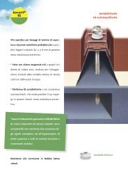
Fissaggi<br />
Si dovrà evitare, per prima cosa, che le lamiere appena posate possano cadere<br />
o ribaltarsi massima attenzione alle lamiere a sbalzo I Le lamiere, man mano<br />
che vengono posate vanno efficacemente fissate alla sottostante struttura <strong>di</strong><br />
sostegno.<br />
1 sistemi <strong>di</strong> fissaggio sono <strong>di</strong>versi potranno essere impiegati: viti autofilettanti<br />
e automaschianti, chio<strong>di</strong> sparati, bottoni <strong>di</strong> saldatura, od anche pioli, usati in<br />
genere nel caso il solaio collaborante debba costituire con la sottostante struttura<br />
una trave composta.<br />
Il progettista dovrà stabilire il tipo ed il numero <strong>di</strong> fissaggi da applicare su<br />
ogni tegolo <strong>di</strong> lamiera, numero che in ogni caso non potrà essere inferiore a tre<br />
fissaggi per tegola su ogni appoggio. La qualità del materiale che costituisce<br />
il fissaggio deve essere certificata. Si dovrà inoltre effettuare una verifica al<br />
rifollamento per la lamiera.<br />
Non è corretto applicare i fissaggi in corrispondenza dell’ala superiore della<br />
lamiera grecata. Se una tale procedura dovesse essere obbligatoriamente adottata<br />
il progettista avrà la responsabilità <strong>di</strong> stu<strong>di</strong>are un idoneo collegamento<br />
rigido.<br />
Non è prevista la sovrapposizione longitu<strong>di</strong>nale <strong>di</strong> due lamiere nel senso della<br />
loro lunghezza il giunto testa a testa sarà posizionato solo in corrispondenza <strong>di</strong><br />
un appoggio ed entrambe le lamiere saranno efficacemente fissate alla struttura.<br />
Può essere utile l’applicazione <strong>di</strong> un nastro adesivo sulle due lamiere per<br />
evitare colature <strong>di</strong> cemento.<br />
Il giunto laterale tra due lamiere contigue si realizza per sovrapposizione ed i<br />
due tegoli <strong>di</strong> lamiera saranno resi solidali applicando rivetti, o viti autofilettanti,<br />
con passo non superiore a 70 cm. in modo da evitare che una lamiera,<br />
caricata più dell’altra (come può avvenire ad esempio in fase <strong>di</strong> getto) abbassandosi<br />
lasci flioruscire il cemento<br />
Deve essere prevista la posa <strong>di</strong> un armatura parallela alle nervature (pari allo<br />
0,2% dell’area <strong>di</strong> cls al <strong>di</strong> sopra dell’estradosso della lamiera) in corrispondenza<br />
degli appoggi con lo scopo <strong>di</strong> verificare momenti negativi <strong>di</strong> continuità. Con<br />
spessore solaio cls <strong>di</strong> 55 mm l’armatura prevista è <strong>di</strong> 1,10 cm 2 /ml.<br />
Per ovviare a problemi <strong>di</strong> ferssurazione e per una ripartizione dei carichi concentrati<br />
risulta necessaria una rete elettrosaldata (posizionata a 20mm dall’estradosso<br />
del cls): con questa rete si può non considerare l’armatura <strong>di</strong> continuità<br />
sugli appoggi, avendo l’avvertenza che la rete elettrosaldata abbia una<br />
sezione <strong>di</strong> almeno 1,10 cm 2 /ml, atta a coprire in corrispondenza degli appoggi<br />
tutta la zona interessata dal momento negativo <strong>di</strong> continuità.<br />
L’altezza complessiva del solaio composto non deve essere minore <strong>di</strong> 80mm; lo<br />
spessore del cls (hc) al <strong>di</strong> sopra dell’estradosso della nervatura della lamiera<br />
non deve essere minore <strong>di</strong> 40 mm, ma se la soletta realizza con la trave portante<br />
una membratura composta, oppure utilizzata come <strong>di</strong>aframma, l’altezza<br />
complessiva non deve essere minore <strong>di</strong> 90 mm con un valore <strong>di</strong> “hc” minimo<br />
<strong>di</strong> 50 mm.<br />
Impiego dei solai collaboranti<br />
Norme <strong>di</strong> riferimento<br />
D M 9 gennaio 1996 “Norme tecniche per il calcolo , l’esecuzione ed il collaudo<br />
delle strutture in cemento armato, normale e precompresso e per le strutture<br />
metalliche” e successivi aggiornamenti e/o mo<strong>di</strong>fiche. CNR 10016- 2000 “Strutture<br />
composte <strong>di</strong> acciaio e calcestruzzo Istruzioni per l’impiego nelle costruzioni”<br />
UNI ENV 1993 - 1 - 3 (Euroco<strong>di</strong>ce 3, parte 1 -3 ) “Regole generali - regole supplementari<br />
per l’impiego dei profili e delle lamiere sottili piegati a freddo”<br />
Materiali<br />
Lamiera S 320 4D per spessore 7/10 S 280 GD UNI EN 10326 (UNI EN 10147 è superata)<br />
Tolleranza negativa della lamiera è = 0.<br />
Calcestruzzo classe 25/30 N / mmq, verificata rispettivamente su provini cilindrici<br />
/cubici.<br />
Armatura in acciaio Fe B 38 K ad aderenza migliorata, controllato in stabilimento.<br />
Posa in opera<br />
SG 75/800<br />
Collaborante<br />
La lamiera grecata in prime fase ( cioè fino a quando il sovrastante getto <strong>di</strong><br />
calcestruzzo non sia maturato ) è l’unico sostegno, non solo per il peso del<br />
calcestruzzo, ma anche per le maestranze e mezzi d’opera, valutati in 100<br />
da N/mq uniformamente <strong>di</strong>stribuiti.<br />
La lamiera verrà <strong>di</strong>sposta sulla sottostante struttura <strong>di</strong> appoggio su una o più<br />
campate, con i conseguenti limiti <strong>di</strong> impiego per quanto riguarda la luce, limiti<br />
che possono essere dovuti o al superamento della freccia elastica (L/180 o in<br />
ogni caso non maggiore <strong>di</strong> 2,0 cm) o al superamento della sollecitazione per<br />
la lamiera nella sua sezione più critica in mezzeria od in corrispondenza <strong>di</strong> un<br />
appoggio interme<strong>di</strong>o.<br />
Nelle tabelle <strong>di</strong> portata non si è presa in considerazione l’ipotesi <strong>di</strong> lamiera<br />
puntellata in fase <strong>di</strong> getto, tale accorgimento potrebbe consentire il superamento<br />
dei limiti precedentemente in<strong>di</strong>cati e riportati nelle tabelle.<br />
Va però effettuato un calcolo apposito perché se in prima fase il puntello si<br />
comporta come un normale appoggio al momento del <strong>di</strong>sarmo, che avverrà<br />
solo dopo la maturazione del getto (mai prima <strong>di</strong> 28 giorni in con<strong>di</strong>zioni normali),<br />
il solaio composto dovrà assorbire un carico concentrato agente dall’alto<br />
verso il basso, pari alla reazione del puntello stesso. Il solaio non potrà essere<br />
assoggettato a carichi <strong>di</strong>versi da quelli in<strong>di</strong>cati in precedenza, sia come entità<br />
che come tipologia, fino alla completa maturazione del calcestruzzo, tenendo<br />
inoltre presente i limiti dovuti alla prima fase.<br />
Si dovrà avere cura pertanto che all’atto del getto il calcestruzzo non<br />
formi dei cumuli la posa del calcestruzzo andrà fatta partendo dagli<br />
appoggi verso la mezzeria delle campate, in modo il più possibile simmetrico.<br />
All’atto del getto le lamiere dovranno essere libere da ogni corpo estraneo,<br />
pulite, prive <strong>di</strong> qualsiasi traccia <strong>di</strong> olio o fango o ghiaccio da qualunque elemento<br />
che possa <strong>di</strong>minuire l’aderenza tra il calcestruzzo e la lamiera grecata.<br />
1
1<br />
Le lamiere danneggiate devono essere scartate.<br />
Dovranno inoltre essere rispettate le normali regole per la composizione,<br />
il getto e la maturazione del calcestruzzo.<br />
Per quanto riguarda il <strong>di</strong>ametro massimo degli inerti la C N R 10016 -2000, punto<br />
7.7.2, prescrive quanto segue: “La <strong>di</strong>mensione nominale dell’inerte <strong>di</strong>pende<br />
dalla più piccola <strong>di</strong>mensione dell’elemento strutturale nel quale il calcestruzzo<br />
bO<br />
Le solette composte sostenute da elementi <strong>di</strong> acciaio o calcestruzzo avranno<br />
una larghezza <strong>di</strong> appoggio minimo <strong>di</strong> 75 mm , con una <strong>di</strong>mensione <strong>di</strong> appoggio<br />
del bordo della lamiera grecata <strong>di</strong> almeno 50 mm [( figure (a) e (c)]. Nel<br />
caso in cui le solette composte siano sostenute da elementi in materiale <strong>di</strong>verso<br />
i valori precedentemente in<strong>di</strong>cati <strong>di</strong>vengono, rispettivamente, pari almeno a<br />
bO<br />
bb<br />
Solai Composti Acciaio Calcestruzzo<br />
Normativa <strong>di</strong>riferimento : Istruzioni CNR 10016-2000<br />
Appoggi (ved. Fig. 4) Fig. 3 Dimensioni <strong>di</strong> lamiera e soletta<br />
Fig. 4<br />
(a) (c) (e)<br />
a) appoggi su acciaio e calcestruzzo<br />
(b) (d) (f)<br />
b) appoggi su altri materiali come muratura o blocchi<br />
è gettato, e non deve superare il più piccolo dei seguenti valori (Fig. 3):<br />
• 0,40 h c<br />
• bo/3 , dove bo è la larghezza me<strong>di</strong>a delle nervature<br />
(minima larghezza nel caso <strong>di</strong> forme con profili rientranti);<br />
• 31,5 mm (staccio C31.5): per lamiera SP75/800 massima <strong>di</strong>mensione: 2 cm.<br />
hc<br />
hp<br />
h<br />
100 e 70 mm [figure (b) e (d)]. Per lamiere continue che poggiano su elementi<br />
<strong>di</strong> acciaio o calcestruzzo l’appoggio minimo sarà <strong>di</strong> 75 mm e se l’appoggio è<br />
costituito da elementi <strong>di</strong> altro materiale la sua <strong>di</strong>mensione minima sarà <strong>di</strong> 100<br />
mm. [fig. (e) ed (f)]<br />
bO<br />
bb<br />
hc<br />
hp<br />
h<br />
Istruzioni base per posa delle lamiere<br />
vedere a completamento le note generali <strong>di</strong> montaggio<br />
1) Pulire la lamiera da olio, fango etc...<br />
2) Posare lamiera con seguenti modalità:<br />
a) Appoggi <strong>di</strong> non continuità (dett.1)<br />
le lamiere devono essere accostate testa a testa (mai sovrapposte)<br />
con appoggio minimo <strong>di</strong> 50 mm. per ogni lamiera<br />
(appoggio struttura acciaio e muro cls)<br />
b) Appoggio <strong>di</strong> continuità (dett.2)<br />
La lamiera dovrà avre un appoggio minimo <strong>di</strong> 75 mm.<br />
su struttura acciaio e muri cls.<br />
c) Appoggio laterale<br />
parallelo alle nervature del pannello <strong>di</strong> lamiera (dett.3)<br />
I pannelli <strong>di</strong> lamiera perimetrali dovranno avere l’appoggio<br />
longitu<strong>di</strong>nale continuo <strong>di</strong> almeno tutta la nervatura esterna.<br />
2) Posa <strong>di</strong> lamiera perimetrale <strong>di</strong> getto.<br />
4) Fissaggi: con viti autofilettanti/automaschianti ø 6,3<br />
come in<strong>di</strong>cato note generali<br />
a) Appoggi <strong>di</strong> non continuità<br />
Un fissaggio ogni greca per tutte e due le lamiere<br />
b) Appoggio <strong>di</strong> continuità<br />
Un fissaggio ogni greca<br />
c) Appoggio laterale<br />
Un fissaggio ogni 25 cm. (dett.3)<br />
d) Giunzione tra due pannelli continui (dett.4)<br />
La giunzione longitu<strong>di</strong>nale tra due pannelli <strong>di</strong> lamiera contigui viene<br />
realizzata per sovrapposizione delle due nervature terminali fissate<br />
tra loro con rivetto o viti autofilettanti ogni 70 cm.<br />
5) Posa <strong>di</strong> eventuale nastro adesivo (dett. 1)<br />
6) Posa <strong>di</strong> rete elettrosaldata<br />
posizionata con opportuni <strong>di</strong>stanziatori a 20 mm. dall’estradosso della<br />
soletta <strong>di</strong> calcestruzzo con l’avvertenza <strong>di</strong> non interruzioni della rete in<br />
corrispondenza degli appoggi: la rete dovrà coprire ai due lati <strong>di</strong> un<br />
appoggio almeno lo 0,30÷ ÷ 0,30 della luce delle due campate contigue.<br />
Per altezza solaio H=12 cm. la rete dovrà avere una maglia minima con<br />
0,9 cm 2 /ml - ø 5 maglia 20x20<br />
Per altezza solaio H=13 cm. la rete dovrà avere una maglia minima con<br />
1,1 cm 2/ml - ø 6 maglia 20x20<br />
7) Getto calcestruzzo<br />
con caratteristiche in<strong>di</strong>cate sulle note generali e con l’accortezza <strong>di</strong> evitare<br />
cumuli <strong>di</strong> calcestruzzo in campata.
SG 75/800<br />
1 1<br />
Collaborante<br />
Spessore<br />
mm.<br />
0,7<br />
0,8<br />
1,0*<br />
1,25*<br />
1,5*<br />
Una campata Portata utile daN/mq<br />
LUCE ( m )<br />
I valori tra () non rispettano il limite <strong>di</strong> freccia L/200<br />
Il calcolo della freccia è stato condotto considerando un carico <strong>di</strong> neve ridotto al 70% come da D.M. gennaio 1996<br />
* Per questo spessore gli irrigi<strong>di</strong>menti risultano non efficaci<br />
Spessore<br />
mm.<br />
0,7<br />
0,8<br />
1,0*<br />
1,25*<br />
1,5*<br />
1 1,5 2 2,2 2,4 2,6 2,8 3,0 3,2 3,4 3,6 3,8 4,0 4,20 4,40<br />
1616 1078 809 644 518 421 343<br />
1918 1280 960 768 622 508 418 345 285<br />
2503 1669 1252 1009 824 679 565 472 397 334<br />
3225 2150 1613 1307 1073 892 747 631 536 457 390 334<br />
3938 2625 1969 1600 1319 1101 927 787 673 578 498 430 373 323<br />
Due campate Portata utile daN/mq<br />
LUCE ( m )<br />
1 1,5 2 2,2 2,4 2,6 2,8 3,0 3,2 3,4 3,6 3,8 4,0 4,20 4,40<br />
1616 1078 809<br />
1918 1280 960 768 622 508 418 345 285<br />
2503 1669 1252 1009 824 679 565 472 397<br />
3225 2150 1613 1307 1073 892 747 631 536 457 390 334 286 245<br />
pp Kg/mq<br />
165,9 8,58<br />
167,1 9,81<br />
169,6 12,26<br />
172,6 15,33<br />
3938 2625 1969 1600 1319 1101 927 787 673 578 498 430 373 323 280 175,7 18,39<br />
pp Kg/mq<br />
165,9 8,58<br />
167,1 9,81<br />
169,6 12,26<br />
172,6 15,33<br />
3938 2625 1969 1600 1319 1101 927 787 673 578 498 430 373 323 280 175,7 18,39<br />
Solai Composti Acciaio Calcestruzzo<br />
Normativa <strong>di</strong>riferimento : Istruzioni CNR 10016-2000<br />
Il calcolo della freccia è stato condotto considerando un carico <strong>di</strong> neve ridotto al 70% come da D.M. gennaio 1996<br />
Spessore<br />
mm.<br />
0,7<br />
0,8<br />
1,0*<br />
1,25*<br />
1,5*<br />
Tre campate Portata utile daN/mq<br />
LUCE ( m )<br />
1 1,5 2 2,2 2,4 2,6 2,8 3,0 3,2 3,4 3,6 3,8 4,0 4,20 4,40<br />
1616 1078 809 644<br />
1918 1280 960 768 622 508 418 345 285 236 194<br />
2503 1669 1252 1009 824 679 565 472 397 334 281<br />
H Solaio = 12 cm.<br />
3225 2150 1613 1307 1073 892 747 631 536 457 390 334 286 245<br />
pp Kg/mq<br />
165,9 8,58<br />
167,1 9,81<br />
169,6 12,26<br />
172,6 15,33<br />
175,7 18,39<br />
Il calcolo della freccia è stato condotto considerando un carico <strong>di</strong> neve ridotto al 70% come da D.M. gennaio 1996<br />
Tabelle <strong>di</strong> portata<br />
( da N/mq ≅ kg/mq )<br />
Profilo SG 75/800 Irrigi<strong>di</strong>menti<br />
superiori<br />
Acciaio S 280 GD UNI EN 10326<br />
Normativa <strong>di</strong> riferimento<br />
CNR. 10022<br />
Distanza tra gli appoggi in metri<br />
Tabelle <strong>di</strong> portata<br />
( da N/mq ≅ kg/mq )<br />
Profilo SG 75/800 Irrigi<strong>di</strong>menti<br />
superiori<br />
Acciaio S 280 GD UNI EN 10326<br />
Normativa <strong>di</strong> riferimento<br />
CNR. 10022<br />
Distanza tra gli appoggi in metri<br />
Tabelle <strong>di</strong> portata<br />
( da N/mq ≅ kg/mq )<br />
Profilo SG 75/800 Irrigi<strong>di</strong>menti<br />
superiori<br />
Acciaio S 280 GD UNI EN 10326<br />
Normativa <strong>di</strong> riferimento<br />
CNR. 10022<br />
Distanza tra gli appoggi in metri<br />
Solai Composti Acciaio Calcestruzzo<br />
Normativa <strong>di</strong>riferimento : Istruzioni CNR 10016-2000<br />
Spessore<br />
mm.<br />
0,7<br />
0,8<br />
1,0*<br />
1,25*<br />
1,5*<br />
Una campata Portata utile daN/mq<br />
LUCE ( m )<br />
I valori tra () non rispettano il limite <strong>di</strong> freccia L/200<br />
Il calcolo della freccia è stato condotto considerando un carico <strong>di</strong> neve ridotto al 70% come da D.M. gennaio 1996<br />
* Per questo spessore gli irrigi<strong>di</strong>menti risultano non efficaci<br />
Spessore<br />
mm.<br />
0,7<br />
0,8<br />
1,0*<br />
1,25*<br />
1,5*<br />
Due campate Portata utile daN/mq<br />
LUCE ( m )<br />
1 1,5 2 2,2 2,4 2,6 2,8 3,0 3,2 3,4 3,6 3,8 4,0 4,20 4,40<br />
1613 1076 807<br />
1911 1274 956 762 615<br />
2498 1666 1250 1004 818 672 556 463<br />
3215 2146 1610 1301 1066 883 738 621 525 445 378 321 273<br />
3930 2622 1927 1696 1313 1093 919 778 662 566 486 418 360 310 266<br />
pp Kg/mq<br />
190,9 8,58<br />
192,1 9,81<br />
194,6 12,26<br />
197,6 15,33<br />
200,7 18,39<br />
Il calcolo della freccia è stato condotto considerando un carico <strong>di</strong> neve ridotto al 70% come da D.M. gennaio 1996<br />
Spessore<br />
mm.<br />
0,7<br />
0,8<br />
1,0*<br />
1,25*<br />
1,5*<br />
Tre campate Portata utile daN/mq<br />
LUCE ( m )<br />
1 1,5 2 2,2 2,4 2,6 2,8 3,0 3,2 3,4 3,6 3,8 4,0 4,20 4,40<br />
1613 1076 807 640<br />
1911 1274 956 762 615 500<br />
2498 1666 1250 1004 818 672 556 463 386 323<br />
H Solaio = 13 cm.<br />
1 1,5 2 2,2 2,4 2,6 2,8 3,0 3,2 3,4 3,6 3,8 4,0 4,20 4,40<br />
1613 1076 807 640 513 413 334<br />
1911 1274 956 762 615 500 409 335<br />
2498 1666 1250 1004 818 672 556 463 386<br />
3215 2146 1610 1301 1066 883 738 621 525 445 378<br />
3930 2622 1927 1596 1313 1093 919 778 662 566 486 418 360<br />
3215 2146 1610 1301 1066 883 738 621 525 445 378 321 273<br />
3930 2622 1927 1696 1313 1093 919 778 662 566 486 418 360 310 266<br />
pp Kg/mq<br />
190,9 8,58<br />
192,1 9,81<br />
194,6 12,26<br />
197,6 15,33<br />
200,7 18,39<br />
pp Kg/mq<br />
190,9 8,58<br />
192,1 9,81<br />
194,6 12,26<br />
197,6 15,33<br />
200,7 18,39<br />
Il calcolo della freccia è stato condotto considerando un carico <strong>di</strong> neve ridotto al 70% come da D.M. gennaio 1996<br />
<strong>di</strong>s.<br />
SG 75/800<br />
Collaborante<br />
Tabelle <strong>di</strong> portata<br />
( da N/mq ≅ kg/mq )<br />
Profilo SG 75/800 Irrigi<strong>di</strong>menti<br />
superiori<br />
Acciaio S 280 GD UNI EN 10326<br />
Normativa <strong>di</strong> riferimento<br />
CNR. 10022<br />
Distanza tra gli appoggi in metri<br />
Tabelle <strong>di</strong> portata<br />
( da N/mq ≅ kg/mq )<br />
Profilo SG 75/800 Irrigi<strong>di</strong>menti<br />
superiori<br />
Acciaio S 280 GD UNI EN 10326<br />
Normativa <strong>di</strong> riferimento<br />
CNR. 10022<br />
Distanza tra gli appoggi in metri<br />
Tabelle <strong>di</strong> portata<br />
( da N/mq ≅ kg/mq )<br />
Profilo SG 75/800 Irrigi<strong>di</strong>menti<br />
superiori<br />
Acciaio S 280 GD UNI EN 10326<br />
Normativa <strong>di</strong> riferimento<br />
CNR. 10022<br />
Distanza tra gli appoggi in metri
Prototipo Spinelli 3800 durante la prova.<br />
Dettaglio del prototipo Spinelli 3800 durante la prova.<br />
Politecnico <strong>di</strong> Milano<br />
Dipartimento <strong>di</strong> ingegneria strutturale<br />
Laboratorio prove materiali<br />
Documentazione Fotografica<br />
Politecnico <strong>di</strong> Milano<br />
Dipartimento <strong>di</strong> ingegneria strutturale<br />
Laboratorio prove materiali<br />
Documentazione Fotografica<br />
Prototipo Spinelli 3800 durante la prova.<br />
Dettaglio del prototipo Spinelli 3800 durante la prova.
Prototipo Spinelli 1600 durante la prova.<br />
Dettaglio del prototipo Spinelli 1600 durante la prova.<br />
Politecnico <strong>di</strong> Milano<br />
Dipartimento <strong>di</strong> ingegneria strutturale<br />
Laboratorio prove materiali<br />
Documentazione Fotografica<br />
Tabella Colori<br />
Bianco<br />
RAL 9010<br />
Rosso Siena<br />
simile<br />
RAL 3009<br />
Testa <strong>di</strong> Moro<br />
simile<br />
RAL 8017<br />
I colori sopraelencati sono normalmente <strong>di</strong>sponibili a magazzino, per <strong>di</strong>sponibilità spessore e formato consultare i nostri commerciali.<br />
Caratteristiche tecniche del “sistema base” <strong>di</strong> preverniciatura<br />
Spessore<br />
Il sistema <strong>di</strong> protezione è costituito da un film secco<br />
<strong>di</strong> 25±3 microns.<br />
Cottura<br />
Il film cotto, secondo le norme AICC n. 23, dovrà<br />
resistere ad almeno 50 “Strusciate” effettuate con<br />
cotone idrofilo imbevuto <strong>di</strong> metil - etil - chetone.<br />
Durezza<br />
Il film sottopposto alla prova <strong>di</strong> durezza, secondo<br />
le norme AICC n˚ 11, dovrà resitere alle scalfitture<br />
eseguite con mina <strong>di</strong> matita F della scala Koh-i-<br />
Noor.<br />
Brillantezza<br />
Misurato con glossmetro GARDNER con angolazione<br />
<strong>di</strong> 60˚ (norme ASTM D523 - AICC n˚ 07) il gloss<br />
speculare dovrà essere compreso fra 25 e 45.<br />
T a b e l l a C o l o r i<br />
Blu Pastello<br />
RAL 5024<br />
Verde<br />
muschio<br />
RAL 6005<br />
Silver<br />
RAL 9006<br />
Resistenza alla piegatura<br />
Applicando un nastro adesivo TESA 104 ad un provino<br />
piegato intorno ad un mandrino <strong>di</strong> <strong>di</strong>ametro<br />
pari a 3 volte lo spessore del provino stesso (3T)<br />
non si dovrà verificare <strong>di</strong>stacco <strong>di</strong> vernice.<br />
Resistenza in nebbia salina<br />
Effettuando la prova secondo il proce<strong>di</strong>mento descritto<br />
dalle norme AICC n˚ 22 si dovranno avere i<br />
seguenti risultati.<br />
• assenza <strong>di</strong> sbollature o penetrazioni lungo<br />
le incisioni dopo 250 ore;<br />
• applicando un nstro adesivo TESA 600, almeno<br />
24 ore dopo l’estrazione della camera <strong>di</strong> prova,<br />
non si dovrà verificare <strong>di</strong>stacco alcuno.<br />
Resistenza in Umidometro<br />
La prova <strong>di</strong> resistenza all’umi<strong>di</strong>tà dovrà essere seguita secondo<br />
quanto previsto dalle Norme AICC n˚ 21. Dopo 1000<br />
ore si potrà avere un leggero ammorbimento e solo qualcheisolatasbollaturanonsuperiorealn˚8ASTMD714.<br />
Bianco Grigio<br />
simile<br />
RAL 9002<br />
Blu Genziana<br />
simile<br />
RAL 5010<br />
Verde Reseda<br />
simile<br />
RAL 6011<br />
Resistenza all’invecchiamento artificiale<br />
La prova <strong>di</strong> resistenza all’invecchiamento artificiale<br />
dovrà essere eseguita secondo quanto previsto<br />
dalle Norme AICC n˚ 20. Dopo 500 ore non si dovrà<br />
rilevare presenza <strong>di</strong> pelature e screpolature.<br />
Applicazione<br />
Sistema Base: preverniciatura per esterni consigliato<br />
in ambienti normali poco inquinati.<br />
Sistema Super: preverniciatura per esterni particolarmente<br />
resistente allo scolorimento allo sfarinamento.<br />
Sistema PVDF: preverniciatura per esterni particolarmente<br />
resistente ai raggi UV ed agli agenti chimici,<br />
consigliato in ambienti aggressivi.<br />
Sistema Plastisol: preverniciatura per esterni/interni<br />
ad elevato potere protettivo consigliato in<br />
presenza <strong>di</strong> aggressivi chimici.<br />
A richiesta potranno essere utilizzati laminati preverniciati con caratteristiche <strong>di</strong> spessore, <strong>di</strong> durabilità e <strong>di</strong> resistenza rispondenti alle con<strong>di</strong>zioni ambientali<br />
più <strong>di</strong>sparate. il ns. Servizio Assistenza Clienti è a Vs. <strong>di</strong>sposizione per consigliarVi il sistema <strong>di</strong> verniciatura più idoneo alle effettive esigenze <strong>di</strong> impiego.<br />
23
Spinelli S.r.l.<br />
Via Laveni, 45 / 47<br />
25030 Adro (Bs)<br />
tel: 030 7450488<br />
fax: 030 7357292<br />
www.<strong>spinelli</strong><strong>srl</strong>.eu<br />
info@<strong>spinelli</strong><strong>srl</strong>.eu<br />
lamiere grecate