F.LLI POGLIANO blindo sbarra - elesud.it
F.LLI POGLIANO blindo sbarra - elesud.it
F.LLI POGLIANO blindo sbarra - elesud.it

Create successful ePaper yourself
Turn your PDF publications into a flip-book with our unique Google optimized e-Paper software.
BLINDOSBARRA ® <strong>POGLIANO</strong>BUSBAR<br />
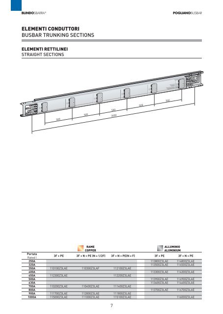
ELEMENTI CONDUTTORI<br />
BUSBAR TRUNKING SECTIONS<br />
ELEMENTI RETTILINEI<br />
STRAIGHT SECTIONS<br />
500 500 500<br />
RAME ALLUMINIO<br />
COPPER ALUMINIUM<br />
Portata<br />
Rated I<br />
3F + PE 3F + N + PE (N = 1/2F) 3F + N + PE(N = F) 3F + PE 3F + N + PE<br />
250A 113800Z3LAE 114800Z3LAE<br />
320A 113500Z3LAE 114500Z3LAE<br />
350A 110100Z3LAE 110300Z3LAF 112100Z3LAE<br />
400A 113300Z3LAE 114300Z3LAE<br />
450A 112300Z3LAE 112200Z3LAE<br />
500A 113900Z3LAE 114900Z3LAE<br />
630A 113400Z3LAE 114400Z3LAE<br />
700A 110200Z3LAE 110400Z3LAE 111400Z3LAE<br />
800A 113700Z3LAE 114700Z3LAE<br />
900A 111700Z3LAE 112800Z3LAE 111800Z3LAE<br />
1000A 115000Z3LAE 111000Z3LAE 115100Z3LAE 116000Z3LAE<br />
3000<br />
7<br />
500<br />
500
BLINDOSBARRA ® <strong>POGLIANO</strong>BUSBAR<br />
ELEMENTI CONDUTTORI<br />
BUSBAR TRUNKING SECTIONS<br />
ELEMENTO RETTILINEO CON GIUNTO DI ESPANSIONE<br />
STRAIGHT SECTION WITH EXPANSION JOINT<br />
Si consiglia l’inserimento dell’elemento<br />
con giunto di<br />
espansione in prossim<strong>it</strong>à dei<br />
giunti di dilatazione del fabbricato<br />
allo scopo di assecondare<br />
gli assestamenti dello<br />
stesso.<br />
!<br />
Elemento da 2975 ÷ 3025<br />
con 50 mm di regolazione<br />
telescopica.<br />
Sections w<strong>it</strong>h expansion<br />
joint must be installed in<br />
proxim<strong>it</strong>y of the building’s<br />
expansion joint.<br />
!<br />
2975 to 3025 (50 mm of<br />
telescopic adjustment)<br />
RAME ALLUMINIO<br />
COPPER ALUMINIUM<br />
Portata<br />
Rated I<br />
3F + PE 3F + N + PE 3F + PE 3F + N + PE<br />
250A 113808Z3LAE 114808Z3LAE<br />
320A 113508Z3LAE 114508Z3LAE<br />
350A 110108Z3LAE 110308Z3LAF<br />
400A 113308Z3LAE 114308Z3LAE<br />
450A 112308Z3LAE 112208Z3LAE<br />
500A 113908Z3LAE 114908Z3LAE<br />
630A 113408Z3LAE 114408Z3LAE<br />
700A 110208Z3LAE 110408Z3LAF<br />
800A 113708Z3LAE 114708Z3LAE<br />
900A 111708Z3LAE 112808Z3LAE<br />
1000A 115008Z3LAE 115108Z3LAE 116008Z3LAE<br />
8
BLINDOSBARRA ® <strong>POGLIANO</strong>BUSBAR<br />
ELEMENTI CONDUTTORI<br />
BUSBAR TRUNKING SECTIONS<br />
COLONNE MONTANTI<br />
RISING MAINS<br />
In caso di installazione in colonna<br />
montante il verso corretto<br />
di montaggio è con la<br />
successione delle fasi 1-N-2-<br />
3 da sinistra a destra guardando<br />
il Blindo<strong>sbarra</strong>. In<br />
questo modo gli sportelli<br />
delle spine si apriranno verso<br />
il basso.<br />
BARRIERA TAGLIAFUOCO<br />
FIREBARRIERS<br />
Gli elementi con barriera tagliafuoco,<br />
realizzata secondo<br />
norma DIN 4102-9 consentono<br />
di compartimentare i<br />
due ambienti attraversati<br />
dalla linea.<br />
La barriera tagliafuoco deve<br />
essere posizionata in corrispondenza<br />
del muro o della<br />
soletta. La lunghezza standard<br />
della barriera tagliafuoco è di<br />
180 mm o di 320 mm.<br />
Per ulteriori informazioni<br />
contattare servizio commerciale<br />
In case of vertical installation<br />
(rising mains) the correct<br />
phase sequence is<br />
1-N-2-3 from left to right<br />
when looking at the busbar<br />
trunking. In this way the<br />
covers of the tap-off outlets<br />
will open downwards.<br />
RAME ALLUMINIO<br />
COPPER ALUMINIUM<br />
Portata<br />
Rated I<br />
3F + PE 3F + N + PE 3F + PE 3F + N + PE<br />
250A 113805Z3LAE 114805Z3LAE<br />
320A 113505Z3LAE 114505Z3LAE<br />
350A 110105Z3LAE 110305Z3LAF<br />
400A 113305Z3LAE 114305Z3LAE<br />
450A 112305Z3LAE 112205Z3LAE<br />
500A 113905Z3LAE 114905Z3LAE<br />
630A 113405Z3LAE 114405Z3LAE<br />
700A 110205Z3LAE 110405Z3LAF<br />
800A 114705Z3LAE<br />
900A 111705Z3LAE 112805Z3LAE<br />
1000A 115105Z3LAE 116005Z3LAE<br />
The sections w<strong>it</strong>h firebarrier<br />
(engineered in compliance<br />
w<strong>it</strong>h DIN Standard 4102-9)<br />
are designed w<strong>it</strong>h the purpose<br />
of segregating the two<br />
sides of a section that goes<br />
through a wall or floor slab.<br />
The firebarrier must be pos<strong>it</strong>ioned<br />
at the wall or slab<br />
crossing. Firebarriers can be<br />
180 mm or 320 mm thick.<br />
For further information call<br />
our sales department.<br />
9<br />
Barriera tagliafuoco<br />
Firebarrier<br />
soff<strong>it</strong>to/pavimento<br />
ceiling / floor<br />
Muro<br />
Wall<br />
Barriera tagliafuoco<br />
Firebarrier
BLINDOSBARRA ® <strong>POGLIANO</strong>BUSBAR<br />
ELEMENTI CONDUTTORI<br />
BUSBAR TRUNKING SECTIONS<br />
ANGOLI DIEDRI<br />
EDGEWISE ELBOWS<br />
Le due estrem<strong>it</strong>à di un elemento<br />
Blindo<strong>sbarra</strong> non<br />
sono ugua li ma complementari.<br />
Percorrendo una linea<br />
posta co me in figura (estrem<strong>it</strong>à<br />
con boccole neutro in<br />
alto) l’angolo di alternativa 1<br />
piega la linea verso sinistra,<br />
quello di al ter nativa 2 piega<br />
la linea verso destra.<br />
!<br />
Sugli angoli e sui T non è<br />
possibile inserire un<strong>it</strong>à di<br />
derivazione<br />
The two ends of a Blindo<strong>sbarra</strong><br />
section are not identical<br />
but complementary. If<br />
you follow the path of an<br />
edgewise elbow pos<strong>it</strong>ioned<br />
like in these two drawings<br />
(eyed neutral up), an alternative<br />
1 elbow bends to the<br />
left, while the alternative 2<br />
elbow bends to the right.<br />
!<br />
On elbows and T’s <strong>it</strong> is not<br />
possible to insert any tap-off<br />
plugs.<br />
Alternativa 1<br />
Alternative 1<br />
Boccole<br />
Bolts<br />
500<br />
10<br />
500<br />
Asole<br />
Eyes<br />
Alternativa 2<br />
Alternative 2<br />
RAME ALLUMINIO<br />
COPPER ALUMINIUM<br />
Portata<br />
Rated I<br />
3F + PE 3F + N + PE 3F + PE 3F + N + PE<br />
250A 113801Z1LAE 114801Z1LAE<br />
320A 113501Z1LAE 114501Z1LAE<br />
350A 110101Z1LAE 110301Z1LAF<br />
400A 113301Z1LAE 114301Z1LAE<br />
450A 112301Z1LAE 112201Z1LAE<br />
500A 113901Z1LAE 114901Z1LAE<br />
630A 113401Z1LAE 114401Z1LAE<br />
700A 110201Z1LAE 110401Z1LAE<br />
800A 113701Z1LAE 114701Z1LAE<br />
900A 111701Z1LAE 112801Z1LAE<br />
1000A 115001Z1LAE 115101Z1LAE 116001Z1LAE<br />
500
BLINDOSBARRA ® <strong>POGLIANO</strong>BUSBAR<br />
ELEMENTI CONDUTTORI<br />
BUSBAR TRUNKING SECTIONS<br />
ANGOLI PIANI<br />
FLATWISE ELBOWS<br />
L’altra tipologia di angolo in<br />
produzione è quella che si<br />
sviluppa sul piano orizzontale;<br />
anche in questi casi si richiede<br />
di specificare l’alternativa.<br />
!<br />
Le alternative degli angoli<br />
indicate in queste pagine si<br />
basano sul montaggio con<br />
neutro in alto.<br />
Same logic on alternatives<br />
as for edgewise elbows<br />
!<br />
The alternatives of the elbows<br />
shown in these pages<br />
are based on assembly w<strong>it</strong>h<br />
neutral up.<br />
11<br />
Boccole<br />
Bolts<br />
Asole<br />
Eyes<br />
Alternativa 2<br />
Alternative 2<br />
600<br />
Alternativa 1<br />
Alternative 1<br />
RAME ALLUMINIO<br />
COPPER ALUMINIUM<br />
Portata<br />
Rated I<br />
3F + PE 3F + N + PE 3F + PE 3F + N + PE<br />
250A 113802Z1LAE 114802Z1LAE<br />
320A 113502Z1LAE 114502Z1LAE<br />
350A 110102Z1LAE 110302Z1LAF<br />
400A 113302Z1LAE 114302Z1LAE<br />
450A 112302Z1LAE 112202Z1LAE<br />
500A 113902Z1LAE 114902Z1LAE<br />
630A 113402Z1LAE 114402Z1LAE<br />
700A 110202Z1LAE 110402Z1LAF<br />
800A 113702Z1LAE 114702Z1LAE<br />
900A 111702Z1LAE 112802Z1LAE<br />
1000A 115002Z1LAE 115102Z1LAE 116002Z1LAE<br />
600 600
BLINDOSBARRA ® <strong>POGLIANO</strong>BUSBAR<br />
ELEMENTI A T<br />
T SECTIONS<br />
Da utilizzare nel caso di esigenze<br />
particolari, per esempio<br />
collegamenti speciali o<br />
derivazioni dalla linea principale.<br />
Dimensioni Standard:<br />
1140+1000+1140 per il piano<br />
ed il diedro.<br />
Come per gli angoli esistono<br />
più alternative<br />
To be utilized in special<br />
connections or for branching<br />
off the main line.<br />
Standard measurements:<br />
1140+1000+1140 (same for<br />
edgewise and flatwise T).<br />
As for normal elbows, there<br />
are two alternatives.<br />
!<br />
Sugli angoli e sui T non è<br />
possibile inserire un<strong>it</strong>à di<br />
derivazione.<br />
On elbows and T’s <strong>it</strong> is not<br />
possible to insert any tapoff<br />
plugs.<br />
T DIEDRO<br />
EDGEWISE T<br />
RAME ALLUMINIO<br />
COPPER ALUMINIUM<br />
Portata<br />
Rated I<br />
3F + PE 3F + N + PE 3F + PE 3F + N + PE<br />
250A 113807Z4LAE 114807Z4LAE<br />
320A 113507Z4LAE 114507Z4LAE<br />
350A 110107Z4LAE 110307Z4LAF<br />
400A 113307Z4LAE 114307Z4LAE<br />
450A 112307Z4LAE 112207Z4LAE<br />
500A 113907Z4LAE 114907Z4LAE<br />
630A 113407Z4LAE 114407Z4LAE<br />
700A<br />
800A<br />
110207Z4LAE 110407Z4LAE<br />
900A 111707Z4LAE 112807Z4LAE<br />
1000A 116007Z4LAE<br />
T PIANO<br />
FLATWISE T<br />
1140<br />
1140 1140<br />
RAME ALLUMINIO<br />
COPPER ALUMINIUM<br />
Portata<br />
Rated I<br />
3F + PE 3F + N + PE 3F + PE 3F + N + PE<br />
250A 113806Z4LAE 114806Z4LAE<br />
320A 113506Z4LAE 114506Z4LAE<br />
350A 110106Z4LAE 110306Z4LAF<br />
400A 113306Z4LAE 114306Z4LAE<br />
450A 112306Z4LAE 112206Z4LAE<br />
500A 113906Z4LAE 114906Z4LAE<br />
630A 113406Z4LAE 114406Z4LAE<br />
700A<br />
800A<br />
110206Z4LAE 110406Z4LAE<br />
900A 111706Z4LAE 112806Z4LAE<br />
1000A 116006Z4LAE<br />
12<br />
1140<br />
1000<br />
1000
BLINDOSBARRA ® <strong>POGLIANO</strong>BUSBAR<br />
ELEMENTI CONDUTTORI<br />
BUSBAR TRUNKING SECTIONS<br />
ELEMENTO TERMINALE (TESTA TRONCA)<br />
TERMINAL ELEMENT<br />
Elemento nel quale le barre<br />
sporgono dall’involucro di<br />
200 mm. e si presentano<br />
con la conformazione illustrata<br />
qui di segu<strong>it</strong>o.<br />
Gli elementi terminali vengono<br />
in genere utilizzati per il<br />
collegamento al quadro di<br />
bassa tensione.<br />
La lunghezza minima è di 500<br />
mm + 200 mm (da inizio tegolo<br />
a fine barre).<br />
Generally for connection to<br />
sw<strong>it</strong>chboard or transformer.<br />
Terminal elements<br />
are preferably straight but<br />
they can be placed on elbows<br />
if necessary. The<br />
bars protrude by 200 mm<br />
from the end of the housing<br />
as shown in the drawing.<br />
Minimum length: 500 mm +<br />
200 mm<br />
9<br />
Al 250A<br />
Cu 350A<br />
26<br />
40<br />
20<br />
9<br />
Al 320A<br />
Cu 450A<br />
34<br />
40<br />
20<br />
Alternativa 1<br />
Alternative 1<br />
Al 400A - 500A<br />
Cu 700A<br />
14<br />
50<br />
40<br />
20<br />
500<br />
200<br />
14<br />
Alternativa 2<br />
Alternative 2<br />
Al 630A<br />
Cu 900A<br />
40<br />
75<br />
13<br />
40<br />
20<br />
14<br />
200<br />
Esecuzione standard<br />
Standard execution<br />
RAME ALLUMINIO<br />
COPPER ALUMINIUM<br />
Portata<br />
Rated I<br />
3F + PE 3F + N + PE 3F + PE 3F + N + PE<br />
250A 113803Z1LAE 114803Z1LAE<br />
320A 113503Z1LAE 114503Z1LAE<br />
350A 110103Z1LAE 110303Z1LAF<br />
400A 113303Z1LAE 114303Z1LAE<br />
450A 112303Z1LAE 112203Z1LAE<br />
500A 113903Z1LAE 114903Z1LAE<br />
630A 113403Z1LAE 114403Z1LAE<br />
700A 110203Z1LAE 110403Z1LAE<br />
800A 113703Z1LAE 114703Z1LAE<br />
900A 111703Z1LAE 111803Z1LAE<br />
1000A 115003Z1LAE 115103Z1LAE 116017Z0000<br />
67,5 7,5<br />
125<br />
Al 800A<br />
Cu 1000A<br />
50<br />
100<br />
16 44 44 53 37 16<br />
67,5<br />
40<br />
212<br />
43,5 43,5<br />
70 70 70<br />
20<br />
14<br />
210<br />
Al 1000A<br />
60<br />
130<br />
31,5<br />
125<br />
40<br />
20
BLINDOSBARRA ® <strong>POGLIANO</strong>BUSBAR<br />
ALIMENTAZIONI<br />
FEED-IN BOX<br />
ALIMENTAZIONE DI TESTATA IP55<br />
END FEED-IN BOX IP55<br />
Si impiega all’estrem<strong>it</strong>à della<br />
linea per alimentare la stessa.<br />
Viene forn<strong>it</strong>a solo in esecuzione<br />
3F + N + PE.<br />
Viene forn<strong>it</strong>a con le boccole<br />
sulle estrem<strong>it</strong>à delle barre<br />
per collegarsi alle asole delle<br />
barre del primo elemento.<br />
NB.<br />
vedi istruzioni di montaggio<br />
forn<strong>it</strong>e con alimentazione<br />
Portata taglia sez. cavi RAME ALLUMINIO A B<br />
Rated I size sec. cable COPPER ALUMINIUM (mm) (mm)<br />
250A 1 2 x 120 114551Z0LAD 500 225<br />
320A 1 2 x 120 114551Z0LAD 500 225<br />
350A 1 2 x 120 112251Z0LAD 500 225<br />
400A 2 2 x 240 114651Z0LAD 500 225<br />
450A 1 2 x 120 112251Z0LAD 500 225<br />
500A 2 2 x 240 114651Z0LAD 500 225<br />
630A 3 3 X 300 114451Z0LAD 500 225<br />
700A 2 2 X 240 110451Z0LAD 500 225<br />
800A 4 4 x 240 114751Z0LAD 500 250<br />
900A 3 3 x 300 111851Z0LAD 500 225<br />
1000A 4 4 x 300 115151Z0LAD 500 260<br />
1000A 5 4 x 300 116051Z0LAD 500 300<br />
ALIMENTAZIONE DI TESTATA IP 55 CON SEZIONATORE/FUSIBILI<br />
END FEED-IN BOX IP55 WITH ISOLATOR/FUSES<br />
Permette la protezione ed il<br />
sezionamento della linea.<br />
Viene forn<strong>it</strong>a solo in esecuzione<br />
3F + N + PE.<br />
696500 586<br />
It’s used to feed a line at one end.<br />
It’s only available in the<br />
3P+N+PE execution.<br />
Supplied w<strong>it</strong>h busbars set for<br />
connection to the eyed end of<br />
a Blindo<strong>sbarra</strong> section.<br />
14<br />
B<br />
Standard Toroide Amperometrico [TA]<br />
It allows for the protection<br />
and isolation of the line.<br />
It’s only available in the<br />
3P+N+PE execution.<br />
D<br />
287<br />
A<br />
466 (D)<br />
521 (T)<br />
380 (D)<br />
435 (T)<br />
RAME ALLUMINIO A B<br />
COPPER ALUMINIUM (mm) (mm)<br />
114551Z0LAT 500 225<br />
114551Z0LAT 500 225<br />
112251Z0LAT 500 225<br />
114651Z0LAT 650 225<br />
112251Z0LAT 500 225<br />
114651Z0LAT 650 225<br />
114451Z0LAT 650 225<br />
110451Z0LAT 650 225<br />
114751Z0LAT 650 250<br />
111851Z0LAT 650 240<br />
115151Z0LAT 650 256<br />
116051Z0LAT 650 300<br />
Portata RAME ALLUMINIO taglia sezione cavi A B C D<br />
Rated I COPPER ALUMINIUM size cable cross section (mm) (mm) (mm) (mm)<br />
250A 114563Z0LAD 1 2 x 120 696 500 586 332<br />
320A 114563Z0LAD 1 2 x 120 696 500 586 332<br />
350A 112263Z0LAD 1 2 x 120 696 500 586 332<br />
400A 114663Z0LAD 2 2 x 120 696 500 586 332<br />
450A 112263Z0LAD 1 2 x 240 696 500 586 332<br />
500A 114663Z0LAD 2 2 x 120 696 500 586 332<br />
630A 114463Z0LAD 3 2 x 240 696 500 586 332<br />
700A 110463Z0LAD 2 3 x 300 696 500 510 332<br />
800A 4 4 x 240 896 500 586 350<br />
900A 111863Z0LAC 3 3 x 300 896 500 510 350<br />
1000A 4-5 3 x 300<br />
A<br />
B<br />
C
BLINDOSBARRA ® <strong>POGLIANO</strong>BUSBAR<br />
ALIMENTAZIONI<br />
FEED-IN BOX<br />
ALIMENTAZIONE INTERMEDIA IP55<br />
INTERMEDIATE FEED-IN BOX IP55<br />
Utilizzabile per ridurre i fenomeni<br />
di caduta di tensione<br />
nelle linee molto lunghe.<br />
Non è possibile realizzare due<br />
alimentazioni indipendenti<br />
per i due tratti.<br />
Viene forn<strong>it</strong>a solo in esecuzione<br />
3F + N + PE.<br />
Lo sviluppo lineare è di 1 metro.<br />
!<br />
ATTENZIONE<br />
la corrente totale derivata<br />
dai due rami della linea NON<br />
potrà essere superiore alla<br />
In della alimentazione.<br />
CAUTION:<br />
the total current branched off<br />
the two sides of the run<br />
MUST NOT BE in excess of<br />
the rated current of the box<br />
C<br />
Portata RAME ALLUMINIO taglia sezione cavi A B C<br />
Rated I COPPER ALUMINIUM size cable cross section (mm) (mm) (mm)<br />
250A 114553Z0LAC 1 2 x 120 350 436 274,5<br />
320A 114553Z0LAC 1 2 x 120 350 436 274,5<br />
350A 112253Z0LAC 1 2 x 120 350 436 274,5<br />
400A 114653Z0LAC 2 2 x 240 450 536 419,5<br />
450A 112253Z0LAC 1 2 x 120 350 436 274,5<br />
500A 114653Z0LAC 2 2 x 240 450 536 419,5<br />
630A 114453Z0LAC 3 3 x 300 450 536 419,5<br />
700A 110453Z0LAC 2 2 x 240 450 536 419,5<br />
800A 4 2 x 240 450 536 419,5<br />
900A 111853Z0LAC 3 3 x 300 450 536 419,5<br />
1000A 4-5 3 x 300 450 536 419,5<br />
SCATOLA DI GIUNZIONE IP55 CON SEZIONATORE/FUSIBILI PER RIDUZIONE DI PORTATA<br />
COUPLING UNIT WITH ISOLATOR/FUSES - IP55 REDUCER RATING<br />
Permette la connessione tra<br />
due linee di differente portata<br />
senza l’impiego di cavi.<br />
Il sezionatore sotto carico (interruttore<br />
di manovra) permette<br />
di mettere fuori tensione<br />
il condotto di portata inferiore.<br />
I fusibili, di tipo NH, garantiscono<br />
la protezione del condotto<br />
di portata inferiore.<br />
Viene forn<strong>it</strong>a solo in esecuzione<br />
3F + N + PE.<br />
!<br />
Per la visione delle taglie<br />
dei conduttori, rimandiamo<br />
a pagina 6.<br />
In sede d’ordine è necessario<br />
specificare le portate dei due<br />
condotti tra cui<br />
si interpone la scatola di<br />
giunzione ed il tipo di testate<br />
(asole/boccole)<br />
Used to reduce voltage drop<br />
in particularly long runs.<br />
It’s not possible to use these<br />
feed-in boxes to feed two<br />
independent runs.<br />
This box is only available in<br />
the 3P+N+PE execution.<br />
It takes up the same space as<br />
a standard 1 meter<br />
section (see drawing).<br />
It provides for the connection<br />
between two different runs of<br />
different rated current w<strong>it</strong>hout<br />
using cables.<br />
By means of the isolator<br />
(sw<strong>it</strong>ch) the run w<strong>it</strong>h the lower<br />
current can be sw<strong>it</strong>ched off.<br />
NH fuses assure<br />
the protection of the<br />
run w<strong>it</strong>h the lower rated<br />
current. It is only<br />
available in the 3P+N+PE<br />
execution.<br />
332<br />
!<br />
For the sizes of the busbar<br />
sections go to page 6.<br />
When you place the order you<br />
must specify the rated current<br />
of the two runs between<br />
which the box is to be placed.<br />
Also specify the type of ends<br />
(eyed or bolted).<br />
15<br />
287<br />
696<br />
696<br />
1000<br />
1000<br />
Codice Tipo di connessione con<br />
Code Connection type for<br />
115460Z0LAD n.2 BS Taglia/size 1<br />
115461Z0LAD BS Taglia/size 1 e 2<br />
115462Z0LAD n.2 BS Taglia/size 2<br />
115463Z0LAD BS Taglia/size 3 e 1<br />
115464Z0LAD BS Taglia/size 3 e 2<br />
115465Z0LAD n.2 BS Taglia/size 3<br />
110065Z0LAA BS Taglia/size 1 e BS 110000/114000<br />
110066Z0LAA BS Taglia/size 2 e BS 110000/114000<br />
110067Z0LAA BS Taglia/size 3 e BS 110000/114000<br />
A<br />
500<br />
B<br />
586
BLINDOSBARRA ® <strong>POGLIANO</strong>BUSBAR<br />
UNITÀ DI DERIVAZIONE<br />
TAP-OFF UNITS<br />
DERIVAZIONE SEMPLICE CON PORTAFUSIBILI<br />
STANDARD TAP-OFF UNIT WITH FUSEHOLDER<br />
GRADO DI PROTEZIONE IP55<br />
La spina tripolare è identificata<br />
con il rosso della targhetta<br />
sullo sportello.<br />
La spina tripolare più neutro<br />
è identificata con il colore blu.<br />
IP55 PROTECTION DEGREE<br />
The 3P tap-off box is identified<br />
by a red plate on the<br />
cover.<br />
The 3P+N box is identified by<br />
a blue plate.<br />
B<br />
16<br />
A<br />
C<br />
Altezza maniglia = 40 mm<br />
Handle height: 40 mm<br />
Spine per fusibili CH fusibili Dimensioni MAX di ingombro Sez. MAX cavi<br />
Tap-off plugs for CH fuses fuses Maximum sizes Max cable cross sec.<br />
Portata 3F + PE 3F + N + PE 3F + N + PE Tipo A B C D Fase Neutro<br />
Rated I N DIRETTO N SEZIONATO Type Phase Neutral<br />
DIRECT NEUTRAL BROKEN NEUTRAL (mm) (mm) (mm) (mm) (mm2 ) (mm2 )<br />
32A 111340Z0LAB 10,3/38 205 80 185 386 25 25<br />
40A 110540Z0LAC 111840Z0LAE 110640Z0LAC 14/51 330 140 190 386 25 25<br />
80A 110541Z0LAC 111841Z0LAE 110641Z0LAC 22/58 330 140 190 386 25 25<br />
100A 111142Z0LAA 111342Z0LAA 22/58 330 140 190 386 50 50<br />
Spine per fusibili VDE fusibili Dimensioni MAX di ingombro Sez. MAX cavi<br />
Tap-off plugs for VDE fuses fuses Maximum sizes Max cable cross sec.<br />
Portata 3F + PE 3F + N + PE 3F + N + PE DIAZED A B C D Fase Neutro<br />
Rated I N DIRETTO N SEZIONATO DIAZED Phase Neutral<br />
DIRECT NEUTRAL BROKEN NEUTRAL (mm) (mm) (mm) (mm) (mm2 ) (mm2 )<br />
25A 110740Z0LAA 110940Z0LAA 110840Z0LAC E 27 330 140 190 386 10 50<br />
63A 110741Z0LAA 110941Z0LAA 110841Z0LAC E 33 330 140 190 386 25 50<br />
Spine per fusibili NEMA fusibili Dimensioni MAX di ingombro Sez. MAX cavi<br />
Tap-off plugs for NEMA fuses fuses Maximum sizes Max cable cross sec.<br />
Portata 3F + PE 3F + N + PE 3F + N + PE Tipo A B C D Fase Neutro<br />
Rated I N DIRETTO N SEZIONATO Type Phase Neutral<br />
DIRECT NEUTRAL BROKEN NEUTRAL (mm) (mm) (mm) (mm) (mm2 ) (mm2 )<br />
30A 110140Z0LAC 111940Z0LAB 110340Z0LAC 30 330 140 190 386 25 25<br />
60A 110141Z0LAC 111941Z0LAB 110341Z0LAC 60 330 140 190 386 25 25<br />
100A 110142Z0LAB - 110342Z0LAC 100 410 140 190 470 50 50<br />
Spine per fusibili NH fusibili Dimensioni MAX di ingombro Sez. MAX cavi<br />
Tap-off plugs for NH fuses fuses Maximum sizes Max cable cross sec.<br />
Portata 3F + PE 3F + N + PE 3F + N + PE Tipo A B C D Fase Neutro<br />
Rated I N DIRETTO N SEZIONATO Type Phase Neutral<br />
DIRECT NEUTRAL BROKEN NEUTRAL (mm) (mm) (mm) (mm) (mm2 ) (mm2 )<br />
125A 110542Z0LAB 110842Z0LAA 110642Z0LAB 0 410 140 190 470 50 50<br />
200A 110143Z0LAC 110643Z0LAC 110343Z0LAC 1 466 190 260 580 150 70<br />
250A 110144Z0LAC 110644Z0LAA 110344Z0LAC 1 671 180 260 785 150 70<br />
Spina di derivazione base vuota fusibili Dimensioni MAX di ingombro Sez. MAX cavi<br />
Tap-off plugs empty base fuses Maximum sizes Max cable cross sec.<br />
Portata 3F + PE 3F + N + PE 3F + N + PE Tipo A B C D Fase Neutro<br />
Rated I N DIRETTO N SEZIONATO Type Phase Neutral<br />
DIRECT NEUTRAL BROKEN NEUTRAL (mm) (mm) (mm) (mm) (mm2 ) (mm2 )<br />
250A - - 110344Z0LAE - 671 180 260 785 150 70<br />
D
BLINDOSBARRA ® <strong>POGLIANO</strong>BUSBAR<br />
UNITÀ DI DERIVAZIONE<br />
TAP-OFF UNITS<br />
DERIVAZIONE CON SEZIONATORE/PORTAFUSIBILI<br />
TAP-OFF PLUG WITH ISOLATOR/FUSEHOLDER<br />
GRADO DI PROTEZIONE IP55<br />
La spina tripolare è identificata<br />
con il rosso della targhetta<br />
sullo sportello.<br />
La spina tripolare più neutro<br />
è identificata con il colore blu.<br />
IP55<br />
IP31<br />
FUSIBILI<br />
FUSES<br />
IP55 PROTECTION DEGREE<br />
The 3P tap-off box is identified<br />
by a red plate on the<br />
cover.<br />
The 3P+N box is identified<br />
by a blue plate.<br />
17<br />
C<br />
Dimensioni MAX di ingombro<br />
maximum clearing size<br />
Portata CODICE versioni A B C D E F Sezione cavi<br />
Rated I Code executions (mm) (mm) (mm) (mm) (mm) (mm) cable cross sec.<br />
125A 114370Z0LAB 3P+PE 450 - 193 36 276 258 1 x 75 mm 2<br />
125A 114470Z0LAB 3P+Nsez+PE 450 - 193 36 276 258 1 x 75 mm 2<br />
125A 114570Z0LAB 3P+Ndir+PE 450 - 193 36 276 258 1 x 75 mm 2<br />
200A 114371Z0LAB 3P+Pe 660 744 250 132 382 356 1 x 150 mm 2<br />
200A 114471Z0LAB 3P+Nsez+PE 660 744 250 132 382 356 1 x 150 mm 2<br />
200A 114571Z0LAB 3P+Ndir+PE 660 744 250 132 382 356 1 x 150 mm 2<br />
315A 114372Z0LAA 3P+PE 650 736 322 132 505 494 2 x 180 mm 2<br />
315A 114472Z0LAA 3P+Nsez+PE 650 736 322 132 505 494 2 x 180 mm 2<br />
315A 114572Z0LAA 3P+Ndir+PE 650 736 322 132 505 494 2 x 180 mm 2<br />
400A 114374Z0LAA 3P+PE 650 736 322 45 418 494 2 x 180 mm 2<br />
400A 114474Z0LAA 3P+Nsez+PE 650 736 322 45 418 494 2 x 180 mm 2<br />
400A 114574Z0LAA 3P+Ndir+PE 650 736 322 45 418 494 2 x 180 mm 2<br />
600A 114375Z0FAA 3P+PE 650 736 322 45 418 494 3 x 240 mm 2<br />
600A 114475Z0FAA 3P+Nsez+PE 650 736 322 45 418 494 3 x 240 mm 2<br />
600A 114575Z0FAA 3P+Ndir+PE 650 736 322 45 418 494 3 x 240 mm 2<br />
Tipo A B C D E<br />
Type (mm) (mm) (mm) (mm) (mm)<br />
30 127 21<br />
60 139 27<br />
100 200 34 3 19 25<br />
B<br />
Tipo 30 e 60<br />
Type 30 e 60<br />
Tipo 100<br />
Type 100<br />
A<br />
A<br />
A B<br />
E<br />
D<br />
F<br />
B<br />
D<br />
C<br />
E
BLINDOSBARRA ® <strong>POGLIANO</strong>BUSBAR<br />
UNITÀ DI DERIVAZIONE<br />
TAP-OFF UNITS<br />
DERIVAZIONE CON INTERRUTTORI AUTOMATICI<br />
TAP-OFF PLUGS WITH MCCB’S<br />
GRADO DI PROTEZIONE IP55 IP55 PROTECTION DEGREE<br />
!<br />
Spine equipaggiate con interruttore<br />
automatico dotato<br />
di sganciatori a microprocessore<br />
che assicurano la<br />
protezione contro sovraccarico<br />
e cortocircu<strong>it</strong>o istantaneo<br />
(funzioni L e I).<br />
Potere di interruzione alla<br />
tensione di 380/415 V<br />
Icu = 35 kA<br />
DERIVAZIONE QUADRO<br />
“SWITCHBOARD” TAP-OFF<br />
!<br />
Tap-off plugs equipped w<strong>it</strong>h<br />
MCCB w<strong>it</strong>h microsw<strong>it</strong>ches<br />
that assure protection from<br />
overload and short-circu<strong>it</strong><br />
(functions L and I):<br />
Breaking capac<strong>it</strong>y at<br />
380/415 V: Icu= 35kA<br />
B<br />
Dimensioni MAX di ingombro<br />
Maximum sizes<br />
Portata 3F + PE 3F + N + PE 3F + N + PE A B C D E F sezione cavi<br />
Rated I N DIRETTO N SEZIONATO (mm) (mm) (mm) (mm) (mm) (mm) cable cross section<br />
DIRECT NEUTRAL BROKEN NEUTRAL (mm2 )<br />
250A 110663Z0LAG 110683Z0LAG 110673Z0LAG 665 250 356 915 740 50 1 x 120<br />
400A 110664Z0LAH 110684Z0LAH 110674Z0LAH 650 330 488 980 736 50 2 x 95<br />
630A 111776Z0LAA 111876Z0LAA 111877Z0LAA 650 330 488 980 736 63 3 x 240<br />
GRADO DI PROTEZIONE IP55<br />
Equipaggiabile secondo necess<strong>it</strong>à<br />
con apparecchiature<br />
modulari.<br />
Predisposte per accettare fino<br />
a 12 moduli DIN.<br />
Guida DIN di fissaggio integrata.<br />
!<br />
Attenzione apparecchiatura<br />
sotto tensione a coperchio<br />
aperto.<br />
Per ulteriori informazioni<br />
consultare il servizio vend<strong>it</strong>e.<br />
IP55 PROTECTION DEGREE<br />
It can be equipped w<strong>it</strong>h<br />
MCB’s<br />
It f<strong>it</strong>s up to 12 DIN modules<br />
DIN rail incorporated<br />
!<br />
CAUTION: equipment live<br />
when the cover is open.<br />
For further information consult<br />
our sales department.<br />
110<br />
18<br />
F<br />
E<br />
A<br />
25<br />
C<br />
370<br />
Portata Codice Poli IP Moduli DIN<br />
Rated I Code Phase IP DIN modules<br />
63A 112252Z0LAA 4P 55 12<br />
100A 112352Z0LAA 4P 55 12<br />
125A 112452Z0LAA 4P 55 12<br />
D<br />
265
BLINDOSBARRA ® <strong>POGLIANO</strong>BUSBAR<br />
COMPLEMENTI ALLA LINEA<br />
ACCESSORIES<br />
COPERTURA DI ESTREMITÀ - IP55<br />
END COVER - IP55<br />
118<br />
118<br />
13<br />
217<br />
STAFFE DI SOSPENSIONE<br />
HALF HANGER<br />
Per la sospensione di costa<br />
utilizzare una staffa ogni 3<br />
metri.<br />
Per la sospensione di piatto<br />
utilizzare una staffa ogni 2<br />
metri.<br />
144<br />
280<br />
304,3<br />
Asola/eye 12,5 x 8,5 mm<br />
32<br />
172 197 222 252<br />
21 28 53 78 108<br />
14<br />
TAGLIA 1 TAGLIA 2 TAGLIA 3 TAGLIA 4 TAGLIA 5<br />
STAFFA RIDOTTA DI SOSTEGNO<br />
HALF HANGER<br />
Per tutti i BLINDOSBARRA di<br />
portata inferiore a 630 A.<br />
Codice 110121Z0AAB<br />
For edgewise installation use<br />
a hanger every 3 meters.<br />
For flatwise installation use<br />
a hanger every 2 meters.<br />
Usable w<strong>it</strong>h all types of Blindo<strong>sbarra</strong><br />
except 630 A on up.<br />
Code 110121Z0AAB<br />
19<br />
Portata RAME ALLUMINIO<br />
Rated I COPPER ALUMINIUM<br />
250A 110110Z0LAF<br />
320A 110110Z0LAF<br />
350A 110110Z0LAF<br />
400A 110110Z0LAF 110210Z0LAF<br />
450A 110110Z0LAF<br />
500A 110210Z0LAF<br />
630A 113410Z0LAF<br />
700A 110210Z0LAF<br />
800A 113710Z0LAF<br />
900A 113410Z0LAF<br />
1000A 113710Z0LAF 116010Z0LAF<br />
Portata RAME ALLUMINIO<br />
Rated I COPPER ALUMINIUM<br />
250A 110120Z0AAB<br />
320A 110120Z0AAB<br />
350A 110120Z0AAB<br />
400A 110120Z0AAB 110220Z0AAB<br />
450A 110120Z0AAB<br />
500A 110220Z0AAB<br />
630A 113420Z0AAB<br />
700A 110220Z0AAB<br />
800A 113720Z0AAB<br />
900A 113420Z0AAB<br />
1000A 113720Z0AAB 116020Z0AAB<br />
13<br />
14<br />
21<br />
118<br />
118<br />
280
BLINDOSBARRA ® <strong>POGLIANO</strong>BUSBAR<br />
ELEMENTI DI FISSAGGIO<br />
BRACKETS<br />
A seconda delle esigenze particolari che si possono venire a creare<br />
nell’installazione degli elementi vengono realizzati direttamente<br />
dalla Pogliano alcuni tipi di supporti particolari per le staffe standard<br />
del BLINDOSBARRA.<br />
PORTASTAFFA A PARETE<br />
WALL BRACKET<br />
codice<br />
code<br />
L = 550 mm 901001Z0AAA<br />
L = 750 mm 901002Z0AAA<br />
PORTASTAFFA A PUTRELLA 500 mm<br />
TRUSS-BEAM BRACKET 500 mm<br />
codice<br />
code<br />
L = 500 mm 901008Z0AAA<br />
COPPIA ROSTRI PER STAFFA A PUTRELLA<br />
PAIR OF TRUSS-BEAM SUPPORTS<br />
codice<br />
code<br />
coppia/couple 901012Z0AAA<br />
MENSOLA FAST 500 mm<br />
Fast bracket 500 mm<br />
codice<br />
code<br />
L = 500 mm 901013Z0AAA<br />
20<br />
For special needs Pogliano can supply special brackets designed<br />
to f<strong>it</strong> the standard hangers of Blindo<strong>sbarra</strong>.<br />
50<br />
30<br />
L<br />
500<br />
500<br />
50<br />
40<br />
150<br />
195
BLINDOSBARRA ® <strong>POGLIANO</strong>BUSBAR<br />
ELEMENTI DI FISSAGGIO<br />
BRACKETS<br />
PROFILATO VERTICALE CON ANCORE DI AGGANCIO<br />
VERTICAL PROFILE 500 MM HOOKS<br />
codice<br />
code<br />
L = 500 mm 901003Z0AAA<br />
FLANGE PORTASTAFFA A SOFFITTO<br />
CEILING FLANGE<br />
codice<br />
code<br />
901004Z0AAA<br />
PROFILATO A U<br />
U PROFILE<br />
Profilato abbinabile con le<br />
flange a soff<strong>it</strong>to<br />
PIASTRA UNIVERSALE<br />
UNIVERSAL PLATE<br />
codice<br />
code<br />
901010Z0AAA<br />
130<br />
codice<br />
code<br />
L = 500 mm 901005Z0AAA<br />
L = 1000 mm 901006Z0AAA<br />
L = 2000 mm 901007Z0AAA<br />
80<br />
145<br />
Profile for ceiling flange<br />
FLANGE PORTASTAFFA A SOFFITTO RINFORZATA<br />
HEAVY DUTY FLANGE<br />
codice<br />
code<br />
901009Z0AAA<br />
21<br />
30<br />
200<br />
130<br />
21<br />
50<br />
41<br />
500<br />
200<br />
L
BLINDOSBARRA ® <strong>POGLIANO</strong>BUSBAR<br />
DATI TECNICI - RAME<br />
TECHNICAL DATA – COPPER<br />
Grado di protezione IP<br />
Protection Degree IP<br />
Intens<strong>it</strong>à nominale I n (A)<br />
Rated Current<br />
Sezione conduttori di fase S F (mmq)<br />
Phase cross section<br />
Sezione conduttori di neutro S N (mmq)<br />
Neutral cross section<br />
Sezione conduttore di protezione (mmq Fe) S PE<br />
Protective conductor cross section<br />
Sezione conduttore di protezione (mmq Cu) S PE<br />
Protective conductor cross section<br />
Tensione nominale di isolamento U i (V)<br />
Insulation rated voltage<br />
Tensione di prova dielettrica in c.a. V eff (V)<br />
Dielectric test voltage<br />
Corrente nominale ammissibile di breve durata trifase I CW 1s (KA)*<br />
Short-circu<strong>it</strong> rated current (short-time) 3P<br />
Corrente nominale ammissibile di breve durata fase-N I CW 1s (KA)*<br />
Short-circu<strong>it</strong> rated current (short-time) P-N<br />
Corrente nominale ammissibile di breve durata fase-PE I CW 1s (KA)*<br />
Short-circu<strong>it</strong> rated current (short-time) P-PE<br />
Corrente nominale di picco ammissibile trifase I pk (KA)**<br />
Short-circu<strong>it</strong> rated current (peak) 3P<br />
Corrente nominale di picco ammissibile fase-N I pk (KA)**<br />
Short-circu<strong>it</strong> rated current (peak) P-N<br />
Corrente nominale di picco ammissibile fase-PE I pk (KA)**<br />
Short-circu<strong>it</strong> rated current (peak) P-PE<br />
Energia specifica passante amm. di breve durata trifase (1s) (A 2 s)* 10 6<br />
Specific energy (short-time) 3P (1s)<br />
Energia specifica passante amm. di breve durata - N(1s) (A 2 s)* 10 6<br />
Specific energy (short-time) P-N (1s)<br />
Energia specifica passante amm. di breve durata - PE (1s) (A 2 s)* 10 6<br />
Specific energy (short-time) P-PE (1s)<br />
Resistenza di fase (mΩ/100m) (1) r F<br />
Phase resistance<br />
Resistenza di fase (mΩ/100m) (2) r F<br />
Phase resistance<br />
Reattanza di fase (mΩ/100m) x F<br />
Phase reactance<br />
Impedenza di fase (mΩ/100m) z F<br />
Phase impedance<br />
Resistenza spira di guasto fase-N (mΩ/100m)<br />
Fault loop resistance<br />
Reattanza spira di guasto fase-N (mΩ/100m)<br />
Fault loop reactance<br />
Impedenza spira di guasto fase-N (mΩ/100m)<br />
Fault loop impedance<br />
Resistenza spira di guasto (mΩ/100m)*** r sp<br />
Fault loop resistance P-N<br />
Reattanza spira di guasto (mΩ/100m)*** x sp<br />
Fault loop reactance P-N<br />
Impedenza spira di guasto (mΩ/100m)*** z sp<br />
Fault loop impedance P-N<br />
Massa (Kg/m) 3F + PE<br />
Mass<br />
Massa (Kg/m) 3F + N + PE<br />
Mass<br />
* Valore efficace della componente simmetrica<br />
** Valore di picco del primo semiperiodo<br />
*** Indicano i valori di resistenza, reattanza ed impedenza di spira di<br />
guasto fase-PE di una linea Blindo<strong>sbarra</strong> di lunghezza = 100 m (spira<br />
di guasto di lunghezza = 200 m).<br />
(1) Valore misurato in corrente continua a regime termico raggiunto con la<br />
corrente nominale<br />
(2) Valore misurato a 50 Hz a regime termico raggiunto con la corrente<br />
nominale<br />
22<br />
55<br />
350<br />
156<br />
156<br />
500<br />
52<br />
1000<br />
3500<br />
25<br />
15<br />
15<br />
51<br />
31<br />
31<br />
625<br />
375<br />
375<br />
11,9<br />
15,4<br />
17,4<br />
23,5<br />
40,2<br />
20,9<br />
45,3<br />
46<br />
67<br />
BLINDOSBARRA ® <strong>POGLIANO</strong>BUSBAR<br />
DATI TECNICI - ALLUMINIO<br />
TECHNICAL DATA – ALUMINIUM<br />
Grado di protezione IP<br />
Protection Degree IP<br />
Intens<strong>it</strong>à nominale I n (A)<br />
Rated Current<br />
Sezione conduttori di fase S F (mmq)<br />
Phase cross section<br />
Sezione conduttori di neutro S N (mmq)<br />
Neutral cross section<br />
Sezione conduttore di protezione (mmq Fe) S PE<br />
Protective conductor cross section<br />
Sezione conduttore di protezione (mmq Cu) S PE<br />
Protective conductor cross section<br />
Tensione nominale di isolamento U i (V)<br />
Insulation rated voltage<br />
Tensione di prova dielettrica in c.a. V eff (V)<br />
Dielectric test voltage<br />
Corrente nominale ammissibile di breve durata trifase I CW 1s (KA)*<br />
Short-circu<strong>it</strong> rated current (short-time) 3P<br />
Corrente nominale ammissibile di breve durata fase-N I CW 1s (KA)*<br />
Short-circu<strong>it</strong> rated current (short-time) P-N<br />
Corrente nominale ammissibile di breve durata fase-PE I CW 1s (KA)*<br />
Short-circu<strong>it</strong> rated current (short-time) P-PE<br />
Corrente nominale di picco ammissibile trifase I pk (KA)**<br />
Short-circu<strong>it</strong> rated current (peak) 3P<br />
Corrente nominale di picco ammissibile fase-N I pk (KA)**<br />
Short-circu<strong>it</strong> rated current (peak) P-N<br />
Corrente nominale di picco ammissibile fase-PE I pk (KA)**<br />
Short-circu<strong>it</strong> rated current (peak) P-PE<br />
Energia specifica passante amm. di breve durata trifase (1s) (A 2 s)* 10 6<br />
Specific energy (short-time) 3P (1s)<br />
Energia specifica passante amm. di breve durata - N(1s) (A 2 s)* 10 6<br />
Specific energy (short-time) P-N (1s)<br />
Energia specifica passante amm. di breve durata - PE (1s) (A 2 s)* 10 6<br />
Specific energy (short-time) P-PE (1s)<br />
Resistenza di fase (mΩ/100m) (1) r F<br />
Phase resistance<br />
Resistenza di fase (mΩ/100m) (2) r F<br />
Phase resistance<br />
Reattanza di fase (mΩ/100m) x F<br />
Phase reactance<br />
Impedenza di fase (mΩ/100m) z F<br />
Phase impedance<br />
Resistenza spira di guasto fase-N (mΩ/100m)<br />
Fault loop resistance<br />
Reattanza spira di guasto fase-N (mΩ/100m)<br />
Fault loop reactance<br />
Impedenza spira di guasto fase-N (mΩ/100m)<br />
Fault loop impedance<br />
Resistenza spira di guasto (mΩ/100m)*** r sp<br />
Fault loop resistance P-N<br />
Reattanza spira di guasto (mΩ/100m)*** x sp<br />
Fault loop reactance P-N<br />
Impedenza spira di guasto (mΩ/100m)*** z sp<br />
Fault loop impedance P-N<br />
Massa (Kg/m) 3F + PE<br />
Mass<br />
Massa (Kg/m) 3F + N + PE<br />
Mass<br />
* Valore efficace della componente simmetrica<br />
** Valore di picco del primo semiperiodo<br />
*** Indicano i valori di resistenza, reattanza ed impedenza di spira di<br />
guasto fase-PE di una linea Blindo<strong>sbarra</strong> di lunghezza = 100 m (spira<br />
di guasto di lunghezza = 200 m).<br />
(1) Valore misurato in corrente continua a regime termico raggiunto con la<br />
corrente nominale<br />
(2) Valore misurato a 50 Hz a regime termico raggiunto con la corrente<br />
nominale<br />
23<br />
55<br />
250<br />
156<br />
156<br />
500<br />
52<br />
1000<br />
3500<br />
25<br />
15<br />
15<br />
51<br />
31<br />
31<br />
625<br />
375<br />
375<br />
20,6<br />
27,0<br />
17,4<br />
32,3<br />
54,0<br />
20,9<br />
57,9<br />
54<br />
76<br />
BLINDOSBARRA ® <strong>POGLIANO</strong>BUSBAR<br />
BS - SERIE 31<br />
BS - 31 VERSION<br />
BS - SERIE 31 - Con Neutro laterale e protezione IP55 - IP20 con sportello aperto<br />
31 version – W<strong>it</strong>h side neutral and IP55 protection – IP20 when tap-off outlet is open<br />
Si tratta di elementi che conservano le caratteristiche<br />
costruttive di elevata qual<strong>it</strong>à che contraddistinguono tutta<br />
la produzione Pogliano BusBar;<br />
• La barra di neutro è installata in posizione esterna<br />
rispetto a quella delle altre fasi<br />
(la sequenza delle fasi sarà quindi N123);<br />
• Il grado di protezione dell’involucro è IP 55;<br />
• È inoltre garant<strong>it</strong>a una protezione IP 2XB a<br />
sportello aperto;<br />
• 2 derivazioni al metro nell’ esecuzione standard<br />
(come esecuzione speciale può essere ordinato con 4<br />
derivazioni/metro);<br />
ATTENZIONE: Le spine ed i vari complementi<br />
della linea non sono intercambiabili con quelli del<br />
BLINDOSBARRA standard.<br />
• I parafiamma inser<strong>it</strong>i come dotazione standard nel<br />
BLINDOSBARRA serie 31 sono realizzati in una<br />
particolare resina poliestere autoestinguente che<br />
garantisce l’indeformabil<strong>it</strong>à del parafiamma stesso<br />
fino ad una temperatura di esercizio pari a<br />
120° centigradi;<br />
• Compatibil<strong>it</strong>à con i sistemi di staffaggio del<br />
BLINDOSBARRA standard.<br />
ATTENZIONE: per informazioni sui numeri di codice e<br />
dettagli tecnici, contattare il servizio commerciale.<br />
BLINDOSBARRA<br />
SERIE 31<br />
Neutro laterale<br />
Side neutral<br />
BLINDOSBARRA<br />
a cinque conduttori<br />
five conductors<br />
N<br />
24<br />
This version has all the qual<strong>it</strong>y design features<br />
Pogliano for which Pogliano is known.<br />
• The neutral bar is pos<strong>it</strong>ioned to the side.<br />
The phase sequence is therefore N123;<br />
• The housing’s protection degree is IP55;<br />
• When the tap-off outlet is open a protection degree<br />
of IP2XB is assured<br />
• Standard version has two tap-off outlets per meter.<br />
On request they can be increased to four<br />
NOTE: tap-off plugs and accessories of this version<br />
are not compatible w<strong>it</strong>h the standard version of Blindo<strong>sbarra</strong>.<br />
• The shutters of the 31 Blindo<strong>sbarra</strong> version are<br />
made of a special polyester resin that assures they<br />
cannot be deformed even at an operating<br />
temperature of 120 degrees Celsius.<br />
• The hangers are compatible w<strong>it</strong>h the standard<br />
version of Blindo<strong>sbarra</strong>.<br />
NOTE: for information on reference numbers and technical<br />
details contact our sales department.<br />
130 105 80<br />
N<br />
Vista in sezione del parafiamma capace<br />
di garantire un grado di protezione IP2XB<br />
Side view of IP2XB shutter<br />
N