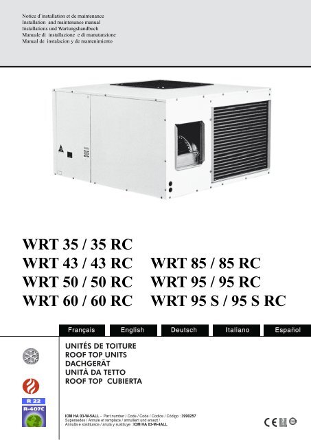
WRT 35 / 35 RC WRT 43 / 43 RC WRT 50 / 50 RC WRT ... - WESPER
WRT 35 / 35 RC WRT 43 / 43 RC WRT 50 / 50 RC WRT ... - WESPER
WRT 35 / 35 RC WRT 43 / 43 RC WRT 50 / 50 RC WRT ... - WESPER

You also want an ePaper? Increase the reach of your titles
YUMPU automatically turns print PDFs into web optimized ePapers that Google loves.
Notice d’installation et de maintenance<br />
Installation and maintenance manual<br />
Installations und Wartungshandbuch<br />
Manuale di installazione e di manutanzione<br />
Manual de instalacion y de mantenimiento<br />
<strong>WRT</strong> <strong>35</strong> / <strong>35</strong> <strong>RC</strong><br />
<strong>WRT</strong> <strong>43</strong> / <strong>43</strong> <strong>RC</strong><br />
<strong>WRT</strong> <strong>50</strong> / <strong>50</strong> <strong>RC</strong><br />
<strong>WRT</strong> 60 / 60 <strong>RC</strong><br />
Unités de toitUre<br />
roof top Units<br />
dachgerät<br />
Unità da tetto<br />
roof top cUbierta<br />
IOM HA 03-W-5ALL - Part number / Code / Code / Codice / Código : 3990257<br />
Supersedes / Annule et remplace / annulliert und ersezt /<br />
Annulla e sostituisce / anula y sustituye : IOM HA 03-W-4ALL<br />
<strong>WRT</strong> 85 / 85 <strong>RC</strong><br />
<strong>WRT</strong> 95 / 95 <strong>RC</strong><br />
<strong>WRT</strong> 95 S / 95 S <strong>RC</strong>
NOTICE D’INSTALLATION<br />
INSTALLATION INSTRUCTION<br />
INSTALLATIONSHANDBUCH<br />
ISTRUZIONI INSTALLAZIONE<br />
INSTRUCCIONES DE INSTALACIÓN
unités de Toiture<br />
<strong>WRT</strong> <strong>35</strong> / <strong>43</strong> / <strong>50</strong> / 60 / 85 / 95 / 95 S<br />
Roof Top units<br />
<strong>WRT</strong> <strong>35</strong> / <strong>43</strong> / <strong>50</strong> / 60 / 85 / 95 / 95 S<br />
2<br />
Dachgerät<br />
<strong>WRT</strong> <strong>35</strong> / <strong>43</strong> / <strong>50</strong> / 60 / 85 / 95 / 95 S
unités de Toiture<br />
<strong>WRT</strong> <strong>35</strong> / <strong>43</strong> / <strong>50</strong> / 60 / 85 / 95 / 95 S<br />
MISE HORS TENSION<br />
OBLIGATOIRE AVANT<br />
TOUTES INTERVENTIONS<br />
DANS LES BOITIERS<br />
ELECTRIQUES<br />
RECOMMANDATIONS<br />
GENERALES<br />
- Avant tout, merci d'avoir porté votre choix<br />
sur un matériel Wesper.<br />
CONSEILS DE SECURITE<br />
- Lorsque vous intervenez sur votre matériel<br />
: suivez les règles de sécurité en vigueur.<br />
- L’installation et l’entretien du matériel devront<br />
être effectués exclusivement par du<br />
personnel qualifié selon les règles de l'art,<br />
les normes et instructions en vigueur.<br />
- Assurez-vous que l'alimentation électrique<br />
disponible et la fréquence du réseau sont<br />
adaptées au courant de fonctionnement<br />
nécessaire compte tenu des conditions<br />
spécifiques de l’emplacement, et du courant<br />
nécessaire à tout autre appareil branché sur<br />
le même circuit.<br />
AVERTISSEMENT<br />
- Couper l'alimentation électrique générale<br />
avant toute intervention ou opération d’entretien.<br />
- Le fabricant décline toute responsabilité et la<br />
garantie ne sera plus valable si ces instructions<br />
d’installation ne sont pas respectées.<br />
- Si vous avez des difficultés, faites appel au<br />
Service Technique de votre zone.<br />
- Avant la mise en place, procédez si possible<br />
au montage des accessoires obligatoires ou<br />
non. (Voir notice livrée avec chaque accessoire)<br />
.- Pour une meilleure connaissance du<br />
produit, nous vous conseillons de consulter<br />
également notre notice technique .<br />
- Les informations contenues dans cette notice sont<br />
sujettes à modifications sans préavis.<br />
Roof Top units<br />
<strong>WRT</strong> <strong>35</strong> / <strong>43</strong> / <strong>50</strong> / 60 / 85 / 95 / 95 S<br />
IT IS MANDATYORY TO<br />
CUTOFF POWER SUPPLY<br />
BEFORE STARTING TO<br />
WORK IN THE ELECTRIC<br />
CASING BOXES.<br />
GENERAL<br />
RECOMMENDATIONS<br />
- Congratulations for having selected an<br />
Wesper air conditioner.<br />
SAFETY DIRECTIONS<br />
- Follow the safety rules in force when you are<br />
working on your appliance.<br />
- Installation and maintenance of the equipment<br />
must only be performed by qualified<br />
specialists in accordance with the rules of<br />
good workmanship and prevailing standards<br />
and instructions.<br />
- Make sure that the power supply and its<br />
frequency are adapted to the required electric<br />
current of operation, taking into account<br />
specific conditions of the location and the<br />
current required for any other appliance<br />
connected with the same circuit.<br />
WARNING<br />
- Cutoff power supply before starting to work<br />
on the appliance.<br />
- The manufacturer declines any responsibility<br />
and the warranty becomes void if these<br />
instructions are not respected.<br />
- If you meet a problem, please call the Technical<br />
Department of your area.<br />
- If possible, assemble the mandatory or optional<br />
accessories before placing the appliance<br />
on its final location.(see instructions provided<br />
with each accessory)<br />
- In order to become fully familiar with the<br />
appliance, we suggest to read also our<br />
Technical Instructions .<br />
- The information contained in these Instructions are<br />
subject to modification without advance notice.<br />
3<br />
Dachgerät<br />
<strong>WRT</strong> <strong>35</strong> / <strong>43</strong> / <strong>50</strong> / 60 / 85 / 95 / 95 S<br />
VOR JEDEM EINGRIFF IN<br />
DEN SCHALTSCHRÄNKEN<br />
UNBEDINGT NETZSTEC-<br />
KER ZIEHEN<br />
ALLGEMEINE<br />
EMPFEHLUNGEN<br />
- Zunächst danken wir Ihnen, daß Sie sich<br />
für ein Wesper Klimagerät entschieden<br />
haben.<br />
SICHERHEITSANWEISUNGEN<br />
- Bei Eingriffen an Ihrem Gerät sind die geltenden<br />
Sicherheitsvorschriften zu befolgen.<br />
- Installation und Wartung der Ausrüstung<br />
dürfen nur von qualifiziertem Personal fachgemäß<br />
und entsprechend den geltenden<br />
Normen und Vorschriften vorgenommen<br />
werden.<br />
- Vergewissern Sie sich, daß Stromversorgung<br />
und Netzfrequenz dem erforderlichen<br />
Betriebsstrom entsprechen, wobei die spezifischen<br />
Bedingungen des Aufstellungsorts<br />
und der erforderliche Strom für die anderen,<br />
an den gleichen Stromkreis angeschlossenen<br />
Geräte zu berücksichtigen sind.<br />
WARNUNG<br />
- Vor jedem Eingriff oder vor Wartungsarbeiten<br />
an dem Gerät muß der Strom abgeschaltet<br />
werden. Bei Nichtbefolgen dieser Anweisungen<br />
lehnt der Hersteller jede Verantwortung<br />
ab, und die Garantie wird ungültig. Bei<br />
Schwierigkeiten wenden Sie sich bitte an<br />
den für Ihren Bezirk zuständigen Technischen<br />
Kundendienst.<br />
- Vor dem Aufstellen falls möglich die vorgeschriebenen<br />
oder wahlfreien Zubehörteile<br />
montieren. (Siehe die mit den jeweiligen<br />
Zubehörteilen gelieferte Anleitung).<br />
- Um mit dem Gerät besser vertraut zu werden,<br />
empfehlen wir, auch unsere Technische<br />
Beschreibung durchzulesen.<br />
- Die in der vorliegenden Beschreibung enthaltenen<br />
Informationen können ohne vorherige Mitteilung<br />
geändert werden.
unités de Toiture<br />
<strong>WRT</strong> <strong>35</strong> / <strong>43</strong> / <strong>50</strong> / 60 / 85 / 95 / 95 S<br />
ATTeNTION R407C<br />
- Votre appareil est chargé en fluide réfrigérant<br />
R407C.<br />
Caractéristiques du fluide réfrigérant R407C<br />
Le R407C est un mélange zéotrope de 3<br />
fluides<br />
• R 32 (CH 2 F 2 ) : 23% en masse<br />
• R 125 (CF 3 CHF 2 ): 25% en masse<br />
• R 134a (CF 3 CH 2 F): 52% en masse<br />
- Les procèdures d'intervention sur le<br />
circuit frigorifique et les caractéristiques<br />
sont différentes du R22. Consulter les<br />
notices correspondantes et respecter<br />
les recommandations lors des interventions.<br />
SOMMAIRe<br />
DeSCRIPTION<br />
Caractéristiques générales .......................5-7<br />
Dimensions .............................................8-10<br />
INSTALLATION<br />
Emplacement de l’unité .............................11<br />
Connexions électriques .............................12<br />
Shémas électriques ..............................13-17<br />
N709 .....................................................18-20<br />
MAINTeNANCe ........................................21<br />
Roof Top units<br />
<strong>WRT</strong> <strong>35</strong> / <strong>43</strong> / <strong>50</strong> / 60 / 85 / 95 / 95 S<br />
SUMMARY<br />
DESCRIPTION<br />
General Specifications ..............................5-7<br />
Dimensions ............................................8-10<br />
INSTALLATION<br />
CAUTION R407C<br />
- Your unit is charged with R407C coolant.<br />
Specifications of R407C coolant<br />
R407C coolant is a zeotropic mixture of three<br />
fluids<br />
• R 32 (CH 2 F 2 ) : 23 % by weight<br />
• R 125 (CF 3 CHF 2 ) : 25 % by weight<br />
• R 134a (CF 3 CH 2 F) : 52 % by weight<br />
- Procedures for working on the cooling<br />
circuit, and the technical characteristics,<br />
are different from the R22. Consult the<br />
corresponding instructions and follow<br />
the recommendations when carrying out<br />
any work.<br />
Location of the Unit ....................................11<br />
Electrical Connections ...............................12<br />
Wirng Diagram ......................................13-17<br />
N709 .....................................................18-20<br />
MAINTENANCE ........................................21<br />
4<br />
Dachgerät<br />
<strong>WRT</strong> <strong>35</strong> / <strong>43</strong> / <strong>50</strong> / 60 / 85 / 95 / 95 S<br />
INHALT<br />
BeSCHReIBuNG<br />
Technische Daten .....................................5-7<br />
Abmessungen .........................................8-10<br />
INSTALLATION<br />
ACHTuNG R407C<br />
- Ihr Gerät ist mit Kältemittel R407C gefüllt.<br />
Eigenschaften des Kältemittels R407C<br />
R407C ist ein zeotropes Gemisch aus 3<br />
Medien<br />
• R 32 (CH 2 F 2 ) : 23% Massenanteil<br />
• R 125 (CF 3 CHF 2 ) : 25% Massenanteil<br />
• R 134a (CF 3 CH 2 F) :52% Massenanteil<br />
- Die eingriffsmethoden für den Kältekreislauf<br />
und die technischen Daten<br />
sind anders als bei dem R22. Bitte einsicht<br />
in die entsprechenden technischen<br />
Beschreibungen nehmen und bei den<br />
eingriffen die empfehlungen beachten.<br />
Aufstellungsort Außenteil ...........................11<br />
Stromanschlüsse .......................................12<br />
Elektrische Anschlusse.........................13-17<br />
N709 .....................................................18-20<br />
WARTuNG ................................................21
unités de Toiture<br />
<strong>WRT</strong> <strong>35</strong> / <strong>43</strong> / <strong>50</strong> / 60 / 85 / 95 / 95 S<br />
COMPOSITION Du COLIS<br />
1 Centrale <strong>WRT</strong><br />
1 Sachet documentation<br />
1 Interrupteur de proximité<br />
SPéCIfICATIONS fRIGORIfIqueS<br />
- Ces unités monoblocs chargées en usine ,<br />
ne neccessitent aucun complément en fluide<br />
frigorigène lors de l'installation.<br />
r 22<br />
r-407c<br />
Roof Top units<br />
<strong>WRT</strong> <strong>35</strong> / <strong>43</strong> / <strong>50</strong> / 60 / 85 / 95 / 95 S<br />
CONTENTS Of PA<strong>RC</strong>EL<br />
1 <strong>WRT</strong> package units<br />
1 bag with reference material<br />
1 Local switch<br />
COOLINg SPECIfICATIONS<br />
- These package units are precharged in the<br />
factory and do not require any additional<br />
refrigerant charge during installation.<br />
5<br />
Dachgerät<br />
<strong>WRT</strong> <strong>35</strong> / <strong>43</strong> / <strong>50</strong> / 60 / 85 / 95 / 95 S<br />
LIefeRuMfANG<br />
1 Zentrale <strong>WRT</strong><br />
1 Beutel mit technischen Unterlagen<br />
1 Näherungsschalter<br />
KäLTeTeCHNISCHe DATeN<br />
- Diese im Werk gefüllten Monobloc-Klimageräte<br />
erfordern bei der Installation kein<br />
Nachfüllen von Kältemittel.<br />
Modèle - Model - Modell <strong>WRT</strong> <strong>35</strong> <strong>WRT</strong> <strong>43</strong> <strong>WRT</strong> <strong>50</strong> <strong>WRT</strong> 60 <strong>WRT</strong> 85 <strong>WRT</strong> 95<br />
PAR CICUIT<br />
2896g 3400g 3400g 3720g 5730g 3400g PER CI<strong>RC</strong>UIT<br />
JE LEITUNG<br />
Modèle - Model - Modell <strong>WRT</strong> <strong>35</strong> <strong>WRT</strong> <strong>43</strong> <strong>WRT</strong> <strong>50</strong> <strong>WRT</strong> 60 <strong>WRT</strong> 85 <strong>WRT</strong> 95S<br />
2510g 3455g <strong>35</strong>40g <strong>35</strong>00g 5<strong>50</strong>0g 6<strong>50</strong>0g 7<strong>50</strong>0g
unités de Toiture<br />
<strong>WRT</strong> <strong>35</strong> / <strong>43</strong> / <strong>50</strong> / 60 / 85 / 95 / 95 S<br />
Roof Top units<br />
<strong>WRT</strong> <strong>35</strong> / <strong>43</strong> / <strong>50</strong> / 60 / 85 / 95 / 95 S<br />
Type d’appareil <strong>WRT</strong> <strong>35</strong> Type of appliance Modell<br />
Alimentation Power supply Betriebsspannung<br />
3N ~ 400V - <strong>50</strong>Hz 3N ~ 400V - <strong>50</strong>Hz 3N ~ 400V - <strong>50</strong>Hz<br />
Froid + Ventil (ou chauffage<br />
Cooling + fan (or heat- Kühlung + Lüftung (oder<br />
thermodynamique)<br />
pump heating) thermodynamische Heizung)<br />
Intensité maximale A 16 Maximum current Max. Strom<br />
Calibre fusible aM A 20 Fuse rating aM Sicherung (träge)<br />
Calibre fusible ASE/VDE** A 20 Fuse rating ASE/VDE** Sicherung SEV/VDE**<br />
Intensité totale démarrage A 58 Total starting current Gesamtanlaufstrom<br />
Section de câble* mm² 5 G 2.5 Cable section* Kabelquerschnitt*<br />
Type d’appareil <strong>WRT</strong> 85 <strong>WRT</strong> 95 Type of appliance Modell<br />
6<br />
Dachgerät<br />
<strong>WRT</strong> <strong>35</strong> / <strong>43</strong> / <strong>50</strong> / 60 / 85 / 95 / 95 S<br />
SPéCIfICATIONS éLeCTRIqueS<br />
r 22<br />
ELECTRIC SPECIfICATIONS eLeKTRISCHe SPezIfKATIONeN<br />
r 22<br />
Type d’appareil <strong>WRT</strong> <strong>43</strong> <strong>WRT</strong> <strong>50</strong> <strong>WRT</strong> 60 Type of appliance Modell<br />
Alimentation Power supply Betriebsspannung<br />
3N ~ 400V - <strong>50</strong>Hz 3N ~ 400V - <strong>50</strong>Hz 3N ~ 400V - <strong>50</strong>Hz<br />
Froid + Ventil (ou chauffage<br />
Cooling + fan (or Kühlung + Lüftung (oder<br />
thermodynamique)<br />
heatpump heating) thermodynamische Heizung)<br />
Intensité maximale A 18.4 15 17 Maximum current Max. Strom<br />
Calibre fusible aM A 25 20 25 Fuse rating aM Sicherung (träge)<br />
Calibre fusible ASE/VDE** A 25 20 25 Fuse rating ASE/VDE** Sicherung SEV/VDE**<br />
Intensité totale démarrage A 60 68 75 Total starting current Gesamtanlaufstrom<br />
Section de câble* mm² 5 G 2.5 5 G 2.5 5 G 2.5 Cable section* Kabelquerschnitt*<br />
r 22<br />
Alimentation Power supply Betriebsspannung<br />
3N ~ 400V - <strong>50</strong>Hz 3N ~ 400V - <strong>50</strong>Hz 3N ~ 400V - <strong>50</strong>Hz<br />
Froid + Ventil (ou chauffage<br />
Cooling + fan (or Kühlung + Lüftung (oder<br />
thermodynamique)<br />
heatpump heating) thermodynamische Heizung)<br />
Intensité maximale A 20 27 Maximum current Max. Strom<br />
Calibre fusible aM A 25 32 Fuse rating aM Sicherung (träge)<br />
Calibre fusible ASE/VDE** A 25 <strong>35</strong> Fuse rating ASE/VDE** Sicherung SEV/VDE**<br />
Intensité totale démarrage A 84 85 Total starting current Gesamtanlaufstrom<br />
Section de câble* mm² 5 G 4 5 G 6 Cable section* Kabelquerschnitt*<br />
IMPORTANT<br />
* Ces valeurs sont données à titre indicatif,<br />
elles doivent être vérifiées et ajustées<br />
en fonction des normes en vigueur: elles<br />
dépendent de l'installation et du choix des<br />
conducteurs.<br />
** Protection par fusible en amont de l'installation<br />
obligatoire:<br />
Fusibles non fournis<br />
Câbles non fournis<br />
IMPORTANT<br />
* These values are given for guidance. They<br />
must be checked and adjusted according to<br />
prevailing standards. They depend on the<br />
system installed and the cables used.<br />
** Afuse must mandatorily be provided on the<br />
system input.<br />
Fuses not supplied<br />
Cables not supplied<br />
WICHTIG<br />
* Diese Werte dienen als Hinweis; sie müssen<br />
in Übereinstimmung mit den geltenden<br />
Normen überprüft und angepaßt werden: sie<br />
hängen jeweils von der Anlage und der Wahl<br />
der Drahtarten ab.<br />
** Vor der Anlage ist ein Schutz durch Sicherung<br />
unbedingt erforderlich:<br />
Sicherungen nicht mitgeliefert<br />
Kabel nicht geliefert
unités de Toiture<br />
<strong>WRT</strong> <strong>35</strong> / <strong>43</strong> / <strong>50</strong> / 60 / 85 / 95 / 95 S<br />
Roof Top units<br />
<strong>WRT</strong> <strong>35</strong> / <strong>43</strong> / <strong>50</strong> / 60 / 85 / 95 / 95 S<br />
7<br />
Dachgerät<br />
<strong>WRT</strong> <strong>35</strong> / <strong>43</strong> / <strong>50</strong> / 60 / 85 / 95 / 95 S<br />
SPéCIfICATIONS éLeCTRIqueS ELECTRIC SPECIfICATIONS eLeKTRISCHe SPezIfKATIONeN<br />
r-407c<br />
Type d’appareil <strong>WRT</strong> <strong>35</strong> Type of appliance Modell<br />
r-407c<br />
r-407c<br />
Alimentation Power supply Betriebsspannung<br />
3N ~ 400V - <strong>50</strong>Hz 3N ~ 400V - <strong>50</strong>Hz 3N ~ 400V - <strong>50</strong>Hz<br />
Froid + Ventil (ou chauffage<br />
Cooling + fan (or heat- Kühlung + Lüftung (oder<br />
thermodynamique)<br />
pump heating) thermodynamische Heizung)<br />
Intensité maximale A 16 Maximum current Max. Strom<br />
Calibre fusible aM A 20 Fuse rating aM Sicherung (träge)<br />
Calibre fusible ASE/VDE** A 20 Fuse rating ASE/VDE** Sicherung SEV/VDE**<br />
Intensité totale démarrage A 58 Total starting current Gesamtanlaufstrom<br />
Section de câble* mm² 5 G 2.5 Cable section* Kabelquerschnitt*<br />
Type d’appareil <strong>WRT</strong> <strong>43</strong> <strong>WRT</strong> <strong>50</strong> <strong>WRT</strong> 60 Type of appliance Modell<br />
Alimentation Power supply Betriebsspannung<br />
3N ~ 400V - <strong>50</strong>Hz 3N ~ 400V - <strong>50</strong>Hz 3N ~ 400V - <strong>50</strong>Hz<br />
Froid + Ventil (ou chauffage<br />
Cooling + fan (or Kühlung + Lüftung (oder<br />
thermodynamique)<br />
heatpump heating) thermodynamische Heizung)<br />
Intensité maximale A 18.4 15 17 Maximum current Max. Strom<br />
Calibre fusible aM A 25 20 25 Fuse rating aM Sicherung (träge)<br />
Calibre fusible ASE/VDE** A 25 20 25 Fuse rating ASE/VDE** Sicherung SEV/VDE**<br />
Intensité totale démarrage A 60 68 75 Total starting current Gesamtanlaufstrom<br />
Section de câble* mm² 5 G 2.5 5 G 2.5 5 G 2.5 Cable section* Kabelquerschnitt*<br />
Type d’appareil <strong>WRT</strong> 85 <strong>WRT</strong> 95 S Type of appliance Modell<br />
Alimentation Power supply Betriebsspannung<br />
3N ~ 400V - <strong>50</strong>Hz 3N ~ 400V - <strong>50</strong>Hz 3N ~ 400V - <strong>50</strong>Hz<br />
Froid + Ventil (ou chauffage<br />
Cooling + fan (or Kühlung + Lüftung (oder<br />
thermodynamique)<br />
heatpump heating) thermodynamische Heizung)<br />
Intensité maximale A 20 25 Maximum current Max. Strom<br />
Calibre fusible aM A 25 32 Fuse rating aM Sicherung (träge)<br />
Calibre fusible ASE/VDE** A 25 <strong>35</strong> Fuse rating ASE/VDE** Sicherung SEV/VDE**<br />
Intensité totale démarrage A 84 112 Total starting current Gesamtanlaufstrom<br />
Section de câble* mm² 5 G 4 5 G 6 Cable section* Kabelquerschnitt*<br />
IMPORTANT<br />
* Ces valeurs sont données à titre indicatif,<br />
elles doivent être vérifiées et ajustées<br />
en fonction des normes en vigueur: elles<br />
dépendent de l'installation et du choix des<br />
conducteurs.<br />
** Protection par fusible en amont de l'installation<br />
obligatoire:<br />
Fusibles non fournis<br />
Câbles non fournis<br />
IMPORTANT<br />
* These values are given for guidance. They<br />
must be checked and adjusted according to<br />
prevailing standards. They depend on the<br />
system installed and the cables used.<br />
** Afuse must mandatorily be provided on the<br />
system input.<br />
Fuses not supplied<br />
Cables not supplied<br />
WICHTIG<br />
* Diese Werte dienen als Hinweis; sie müssen<br />
in Übereinstimmung mit den geltenden<br />
Normen überprüft und angepaßt werden: sie<br />
hängen jeweils von der Anlage und der Wahl<br />
der Drahtarten ab.<br />
** Vor der Anlage ist ein Schutz durch Sicherung<br />
unbedingt erforderlich:<br />
Sicherungen nicht mitgeliefert<br />
Kabel nicht geliefert
unités de Toiture<br />
<strong>WRT</strong> <strong>35</strong> / <strong>43</strong> / <strong>50</strong> / 60 / 85 / 95 / 95 S<br />
MODe De MANuTeNTION<br />
POIDS NeT<br />
INSTALLATION De L'uNITé<br />
- Dégagement minimum à prévoir pour accès<br />
à la maintenance.<br />
- DANS Le CAS D'uNe INSTALLATION Au<br />
PLAfOND, ce dernier doit supporter <strong>35</strong>0Kg<br />
minimum.<br />
- Diamètre des tiges filletées pour fixation au<br />
plafond : Ø10 MINI / Ø18 MAxI.<br />
Roof Top units<br />
<strong>WRT</strong> <strong>35</strong> / <strong>43</strong> / <strong>50</strong> / 60 / 85 / 95 / 95 S<br />
8<br />
Dachgerät<br />
<strong>WRT</strong> <strong>35</strong> / <strong>43</strong> / <strong>50</strong> / 60 / 85 / 95 / 95 S<br />
hANDLINg HANDHABuNG DeS GeRâTS<br />
NET WEIghT<br />
- Sens des fourches pour chariot élévateur<br />
Fork direction on fork lift truck<br />
Richtung der Gabeln bei Gabelstapler<br />
INSTALLATION Of ThE UNIT<br />
- Minimum clearance to be provided for maintenance<br />
access<br />
- fOR CEILINg INSTALLATION, the ceiling<br />
must be capable of withstanding a minimum<br />
load of <strong>35</strong>0kg<br />
- Diameter of threaded rods for ceiling installation:<br />
MIN. 10 MM, MAx. 18 MM.<br />
NeTTOGeWICHT<br />
Modèle - Model - Modell <strong>WRT</strong> <strong>35</strong> <strong>WRT</strong> <strong>43</strong> <strong>WRT</strong> <strong>50</strong> <strong>WRT</strong> 60 <strong>WRT</strong> 85<br />
<strong>WRT</strong> 95 <strong>WRT</strong><br />
95 S<br />
Froid seul -Cooling only -Nur Kühlung 137 Kg 197 Kg 207 Kg 213 Kg 262 Kg 307 Kg<br />
Réversible - Heatpump - Wärmepumpe 140 Kg 200 Kg 210 Kg 216 Kg 265 Kg 310 Kg<br />
Aire de service minimale (mm) -Minimum clearance (mm) -min. Wartungsfreiraum (mm)<br />
INSTALLATION DeS INNeNTeILS<br />
- Mindestfreiraum zum Zugang zwecks Wartungsarbeiten<br />
vorsehen.<br />
a b c d e<br />
600 800 600 400 3000<br />
- IM fALLe eINeR DeCKeNMONTAGe muß<br />
die Tragfähigkeit der Decke mindestens<br />
<strong>35</strong>0kg betragen.<br />
- Durchmesser der Schraubenspindeln zur<br />
Befestigung an der Decke : Ø MIN. 10,<br />
ØMAx. 18.
unités de Toiture<br />
<strong>WRT</strong> <strong>35</strong> / <strong>43</strong> / <strong>50</strong> / 60 / 85 / 95 / 95 S<br />
Roof Top units<br />
<strong>WRT</strong> <strong>35</strong> / <strong>43</strong> / <strong>50</strong> / 60 / 85 / 95 / 95 S<br />
9<br />
Dachgerät<br />
<strong>WRT</strong> <strong>35</strong> / <strong>43</strong> / <strong>50</strong> / 60 / 85 / 95 / 95 S<br />
DIMeNSIONS <strong>WRT</strong> <strong>35</strong> DIMENSIONS <strong>WRT</strong> <strong>35</strong> ABMeSSuNGeN <strong>WRT</strong> <strong>35</strong><br />
1148<br />
683<br />
25.4<br />
1090<br />
83<br />
145<br />
1200 mounting centres<br />
25<br />
155 390 390 155<br />
234 292<br />
156 272<br />
5<strong>35</strong><br />
144<br />
DIMeNSIONS <strong>WRT</strong> <strong>43</strong> - <strong>50</strong> - 60 DIMENSIONS <strong>WRT</strong> <strong>43</strong> - <strong>50</strong> - 60 ABMeSSuNGeN <strong>WRT</strong> <strong>43</strong> - <strong>50</strong> - 60<br />
1320<br />
782<br />
25.4<br />
1320<br />
85<br />
155<br />
25<br />
154 470 556 140<br />
1388<br />
47<br />
B<br />
A<br />
1120<br />
C D<br />
E<br />
99 561<br />
47<br />
87<br />
A B C D E<br />
<strong>43</strong> 233 292 141 272 108<br />
<strong>50</strong><br />
60<br />
264 345 98 316 107<br />
1408<br />
761<br />
47<br />
100 579<br />
90
unités de Toiture<br />
<strong>WRT</strong> <strong>35</strong> / <strong>43</strong> / <strong>50</strong> / 60 / 85 / 95 / 95 S<br />
1184<br />
1320<br />
137 <strong>50</strong>8 538<br />
85<br />
1320<br />
Roof Top units<br />
<strong>WRT</strong> <strong>35</strong> / <strong>43</strong> / <strong>50</strong> / 60 / 85 / 95 / 95 S<br />
157<br />
1378 mounting centres<br />
25 duct flanges<br />
Ø 25,40<br />
1029<br />
10<br />
81 402<br />
56 740<br />
Dachgerät<br />
<strong>WRT</strong> <strong>35</strong> / <strong>43</strong> / <strong>50</strong> / 60 / 85 / 95 / 95 S<br />
DIMeNSIONS <strong>WRT</strong> 85 DIMENSIONS <strong>WRT</strong> 85 ABMeSSuNGeN <strong>WRT</strong> 85<br />
978<br />
25.4<br />
1320<br />
85<br />
155<br />
25<br />
154 470 556 140<br />
1320<br />
1388<br />
DIMeNSIONS <strong>WRT</strong> 95 / 95 S DIMENSIONS <strong>WRT</strong> 95 / 95 S ABMeSSuNGeN <strong>WRT</strong> 95 / 95 S<br />
264 344<br />
90<br />
264 345<br />
98<br />
316<br />
1408<br />
130<br />
1408<br />
739<br />
47<br />
90<br />
37<br />
806<br />
99<br />
99<br />
47<br />
1032<br />
90
unités de Toiture<br />
<strong>WRT</strong> <strong>35</strong> / <strong>43</strong> / <strong>50</strong> / 60 / 85 / 95 / 95 S<br />
RACCORDeMeNT HyDRAuLIque<br />
DeS CONDeNSATS<br />
- Surélever l'appareil pour la réalisation<br />
du syphon sur le tuyau d'évacuation des<br />
condensats.<br />
- Orifice d'évacuation : Ø 1"<br />
- ATTeNTION : Ne jamais braser le tuyau<br />
d'évacuation des condensats sur les<br />
raccords sortant de l'appareil.<br />
ATTeNTION<br />
- Pour les modèles Réversibles, dans le cas où<br />
la température extérieure peut être inférieure<br />
à 1°C, prévoir un système prévenant des<br />
risques de prise en glace des condensats<br />
(cordon chauffant par exemple).<br />
Roof Top units<br />
<strong>WRT</strong> <strong>35</strong> / <strong>43</strong> / <strong>50</strong> / 60 / 85 / 95 / 95 S<br />
CONDENSATE DRAIN LINE<br />
- Raise the appliance to provide traps on the<br />
condensate drain lines<br />
- Drain port: dia. 1"<br />
- CAUTION: Never braze the condensate<br />
drain pipe to the appliance outlet fittings.<br />
CAUTION<br />
- For Heatpump models, if the outdoor temperature<br />
is likely to fall below +1°C, provide<br />
a system to prevent the condensates from<br />
freezing (e.g. heating cord).<br />
11<br />
Dachgerät<br />
<strong>WRT</strong> <strong>35</strong> / <strong>43</strong> / <strong>50</strong> / 60 / 85 / 95 / 95 S<br />
HyDRAuLIKANSCHLuSS fÜR<br />
KONDeNSWASSeR<br />
- Das Gerät muß erhöht aufgestellt werden, um<br />
den Siphon des Kondenswasserabflußrohrs<br />
herstellen zu können.<br />
- Abflußöffnung : Ø 1"<br />
- ACHTuNG :<br />
Das Kondenswasserabflußrohr niemals<br />
an die austretenden Anschlußstutzen des<br />
Gerätes löten.<br />
75mm mini<br />
ACHTuNG<br />
~ 1<strong>50</strong>mm<br />
10mm/m mini<br />
- Bei Ausführungen mit Wärmepumpe muß,<br />
falls die Außentemperatur niedriger als 1°C<br />
sein kann, ein System vorgesehen werden,<br />
um ein Gefrieren des Kondenswassers zu<br />
vermeiden (beispielsweise eine Heizschnur).
unités de Toiture<br />
<strong>WRT</strong> <strong>35</strong> / <strong>43</strong> / <strong>50</strong> / 60 / 85 / 95 / 95 S<br />
RACCORDeMeNTS éLeCTRIqueS<br />
- Ces machines monoblocs sont équipées de<br />
base d'un interrupteur de proximité, faisant<br />
office de bornier d'alimentation générale.<br />
- Possibilité de cadenasser l'interrupteur<br />
- un disjoncteur ou un porte fusible (non<br />
fourni) doit être installé en amont de<br />
l'unité, conformément au schéma électrique;<br />
pour les calibres, se reporter aux<br />
spécifications électriques.<br />
Pour raccorder, utiliser un tournevis POZI-<br />
DRIV M3,5 Form Z.<br />
Roof Top units<br />
<strong>WRT</strong> <strong>35</strong> / <strong>43</strong> / <strong>50</strong> / 60 / 85 / 95 / 95 S<br />
ELECTRICAL CONNECTIONS<br />
- These package units are equipped with a local<br />
switch used as general terminal board.<br />
- The switch can be padlocked.<br />
- A circuit breaker or fuse holder (not<br />
supplied) must be installed upstream of<br />
the unit in accordance with the circuit<br />
diagram. for the ratings, refer to the<br />
electrical specifications.<br />
Use a Pozidrive M3.5 screwdriver, Form Z,<br />
to make the connections.<br />
12<br />
Dachgerät<br />
<strong>WRT</strong> <strong>35</strong> / <strong>43</strong> / <strong>50</strong> / 60 / 85 / 95 / 95 S<br />
eLeKTRISCHe ANSCHLÜSSe<br />
- Diese Monobloc-Geräte sind in ihrer Grundausführung<br />
mit einem Näherungsschalter<br />
ausgerüstet, der als Anschlußklemmenleiste<br />
dient.<br />
- Der Schalter kann mit einem Vorhängeschloß<br />
verriegelt werden.<br />
- Vor dem Gerät muß ein Sicherungsautomat<br />
oder ein Sicherungshalter (nicht<br />
mitgeliefert) angebracht werden, entsprechend<br />
dem Stromlaufplan ; die Größen<br />
sind den elektrischen Spezifikationen zu<br />
entnehmen.<br />
- Appuyer pour le déclipsage et la désolidarisation<br />
du bloc "interruoteur de proximité"<br />
sur le panneau électrique..<br />
- Press to unclip and withdraw the "local<br />
switch" unit on the terminal board.<br />
- Drücken, um den Näherungsschalterblock<br />
zu lösen und von der Schalttafel zu trennen.<br />
Couple de serrage maxi : 2.1 Nm<br />
Max.tightening torque : 2.1 Nm<br />
Max.Anziehmoment : 2.1 Nm<br />
3N~400V-<strong>50</strong>Hz<br />
Für den Anschluß einen Schraubendreher<br />
POZIDRIV M3,5 Form Z, benutzen.
unités de Toiture<br />
<strong>WRT</strong> <strong>35</strong> / <strong>43</strong> / <strong>50</strong> / 60 / 85 / 95 / 95 S<br />
SCHéMA éLeCTRIque :<br />
SE : 3038 <strong>WRT</strong> <strong>35</strong> C/<strong>RC</strong><br />
3-Phases 400/230 V+/-10% <strong>50</strong>Hz<br />
ATTeNTION<br />
Ce schéma est correct au moment de la<br />
publication.<br />
Les variantes en fabrication peuvent<br />
entraîner des modifications. Reportezvous<br />
toujours au schéma livré avec le<br />
produit.<br />
T1SEC<br />
T1PRI<br />
Roof Top units<br />
<strong>WRT</strong> <strong>35</strong> / <strong>43</strong> / <strong>50</strong> / 60 / 85 / 95 / 95 S<br />
WIRINg DIAgRAM :<br />
SE : 3038 <strong>WRT</strong> <strong>35</strong> C/<strong>RC</strong><br />
3-Phase 400/230 V+/-10% <strong>50</strong>Hz<br />
TAKE CARE!<br />
This wiring diagram is correct at the time<br />
of publication. Manufacturing changes<br />
can lead to modifications. Always refer to<br />
the diagram supplied with the product.<br />
13<br />
Dachgerät<br />
<strong>WRT</strong> <strong>35</strong> / <strong>43</strong> / <strong>50</strong> / 60 / 85 / 95 / 95 S<br />
SCHALTPLäNe :<br />
SE : 3038 <strong>WRT</strong> <strong>35</strong> C/<strong>RC</strong><br />
3~ 400/230 V+/-10% <strong>50</strong>Hz<br />
ACHTuNG!<br />
Dieser Stromlaufplan ist zum zeitpunkt<br />
der Veröffentlichung gültig. In Herstellung<br />
befindliche Varianten können änderungen<br />
mit sich bringen. In jedem fall den mit<br />
dem Produkt gelieferten Stromlaufplan<br />
hinzuziehen.<br />
R1
unités de Toiture<br />
<strong>WRT</strong> <strong>35</strong> / <strong>43</strong> / <strong>50</strong> / 60 / 85 / 95 / 95 S<br />
SCHéMA éLeCTRIque :<br />
SE : 3024 <strong>WRT</strong> <strong>43</strong> C/<strong>RC</strong><br />
3-Phases 400/230 V+/-10% <strong>50</strong>Hz<br />
ATTeNTION<br />
Ce schéma est correct au moment de la<br />
publication.<br />
Les variantes en fabrication peuvent<br />
entraîner des modifications. Reportezvous<br />
toujours au schéma livré avec le<br />
produit.<br />
T1SEC<br />
T1PRI<br />
Roof Top units<br />
<strong>WRT</strong> <strong>35</strong> / <strong>43</strong> / <strong>50</strong> / 60 / 85 / 95 / 95 S<br />
WIRINg DIAgRAM :<br />
SE : 3024 <strong>WRT</strong> <strong>43</strong> C/<strong>RC</strong><br />
3-Phase 400/230 V+/-10% <strong>50</strong>Hz<br />
TAKE CARE!<br />
This wiring diagram is correct at the time<br />
of publication. Manufacturing changes<br />
can lead to modifications. Always refer to<br />
the diagram supplied with the product.<br />
14<br />
R1<br />
Dachgerät<br />
<strong>WRT</strong> <strong>35</strong> / <strong>43</strong> / <strong>50</strong> / 60 / 85 / 95 / 95 S<br />
SCHALTPLäNe :<br />
SE : 3024 <strong>WRT</strong> <strong>43</strong> C/<strong>RC</strong><br />
3~ 400/230 V+/-10% <strong>50</strong>Hz<br />
ACHTuNG!<br />
Dieser Stromlaufplan ist zum zeitpunkt<br />
der Veröffentlichung gültig. In Herstellung<br />
befindliche Varianten können änderungen<br />
mit sich bringen. In jedem fall den mit<br />
dem Produkt gelieferten Stromlaufplan<br />
hinzuziehen.
unités de Toiture<br />
<strong>WRT</strong> <strong>35</strong> / <strong>43</strong> / <strong>50</strong> / 60 / 85 / 95 / 95 S<br />
SCHéMA éLeCTRIque :<br />
SE : 3039 <strong>WRT</strong> <strong>50</strong>-60-85-95S C/<strong>RC</strong> 3 -<br />
Phases 400/230 V+/-10% <strong>50</strong>Hz<br />
ATTeNTION<br />
Ce schéma est correct au moment de la<br />
publication.<br />
Les variantes en fabrication peuvent<br />
entraîner des modifications. Reportezvous<br />
toujours au schéma livré avec le<br />
produit.<br />
<br />
<br />
<br />
<br />
Roof Top units<br />
<strong>WRT</strong> <strong>35</strong> / <strong>43</strong> / <strong>50</strong> / 60 / 85 / 95 / 95 S<br />
WIRINg DIAgRAM :<br />
SE : 3039 <strong>WRT</strong> <strong>50</strong>-60-85-95S C/<strong>RC</strong><br />
3-Phase 400/230 V+/-10% <strong>50</strong>Hz<br />
TAKE CARE!<br />
This wiring diagram is correct at the time<br />
of publication. Manufacturing changes<br />
can lead to modifications. Always refer to<br />
the diagram supplied with the product.<br />
<br />
15<br />
<br />
<br />
Dachgerät<br />
<strong>WRT</strong> <strong>35</strong> / <strong>43</strong> / <strong>50</strong> / 60 / 85 / 95 / 95 S<br />
SCHALTPLäNe :<br />
SE : 3039 <strong>WRT</strong> <strong>50</strong>-60-85-95S C/<strong>RC</strong><br />
3~ 400/230 V+/-10% <strong>50</strong>Hz<br />
ACHTuNG!<br />
Dieser Stromlaufplan ist zum zeitpunkt<br />
der Veröffentlichung gültig. In Herstellung<br />
befindliche Varianten können änderungen<br />
mit sich bringen. In jedem fall den mit<br />
dem Produkt gelieferten Stromlaufplan<br />
hinzuziehen.
unités de Toiture<br />
<strong>WRT</strong> <strong>35</strong> / <strong>43</strong> / <strong>50</strong> / 60 / 85 / 95 / 95 S<br />
SCHéMA éLeCTRIque :<br />
SE : 3041 <strong>WRT</strong> 95 C/<strong>RC</strong> POWER<br />
3-Phases 400/230 V+/-10% <strong>50</strong>Hz<br />
ATTeNTION<br />
Ce schéma est correct au moment de la<br />
publication.<br />
Les variantes en fabrication peuvent<br />
entraîner des modifications. Reportezvous<br />
toujours au schéma livré avec le<br />
produit.<br />
Roof Top units<br />
<strong>WRT</strong> <strong>35</strong> / <strong>43</strong> / <strong>50</strong> / 60 / 85 / 95 / 95 S<br />
WIRINg DIAgRAM :<br />
SE : 3041 <strong>WRT</strong> 95 C/<strong>RC</strong> POWER<br />
3-Phase 400/230 V+/-10% <strong>50</strong>Hz<br />
TAKE CARE!<br />
This wiring diagram is correct at the time<br />
of publication. Manufacturing changes<br />
can lead to modifications. Always refer to<br />
the diagram supplied with the product.<br />
16<br />
Dachgerät<br />
<strong>WRT</strong> <strong>35</strong> / <strong>43</strong> / <strong>50</strong> / 60 / 85 / 95 / 95 S<br />
SCHALTPLäNe :<br />
SE : 3041 <strong>WRT</strong> 95 C/<strong>RC</strong> POWER<br />
3~ 400/230 V+/-10% <strong>50</strong>Hz<br />
ACHTuNG!<br />
Dieser Stromlaufplan ist zum zeitpunkt<br />
der Veröffentlichung gültig. In Herstellung<br />
befindliche Varianten können änderungen<br />
mit sich bringen. In jedem fall den mit<br />
dem Produkt gelieferten Stromlaufplan<br />
hinzuziehen.
unités de Toiture<br />
<strong>WRT</strong> <strong>35</strong> / <strong>43</strong> / <strong>50</strong> / 60 / 85 / 95 / 95 S<br />
SCHéMA éLeCTRIque :<br />
SE : 3040 <strong>WRT</strong> 95 C/<strong>RC</strong> CONTROL<br />
1-Phase 230 V+/-10% <strong>50</strong>Hz<br />
ATTeNTION<br />
Ce schéma est correct au moment de la<br />
publication.<br />
Les variantes en fabrication peuvent<br />
entraîner des modifications. Reportezvous<br />
toujours au schéma livré avec le<br />
produit.<br />
T1SEC<br />
T1PRI<br />
Roof Top units<br />
<strong>WRT</strong> <strong>35</strong> / <strong>43</strong> / <strong>50</strong> / 60 / 85 / 95 / 95 S<br />
WIRINg DIAgRAM :<br />
SE : 3040 <strong>WRT</strong> 95 C/<strong>RC</strong> CONTROL<br />
1-Phase 230 V+/-10% <strong>50</strong>Hz<br />
TAKE CARE!<br />
This wiring diagram is correct at the time<br />
of publication. Manufacturing changes<br />
can lead to modifications. Always refer to<br />
the diagram supplied with the product.<br />
17<br />
Dachgerät<br />
<strong>WRT</strong> <strong>35</strong> / <strong>43</strong> / <strong>50</strong> / 60 / 85 / 95 / 95 S<br />
SCHALTPLäNe :<br />
SE : 3040 <strong>WRT</strong> 95 C/<strong>RC</strong> CONTROL<br />
1~ 230 V+/-10% <strong>50</strong>Hz<br />
ACHTuNG!<br />
Dieser Stromlaufplan ist zum zeitpunkt<br />
der Veröffentlichung gültig. In Herstellung<br />
befindliche Varianten können änderungen<br />
mit sich bringen. In jedem fall den mit<br />
dem Produkt gelieferten Stromlaufplan<br />
hinzuziehen.
unités de Toiture<br />
<strong>WRT</strong> <strong>35</strong> / <strong>43</strong> / <strong>50</strong> / 60 / 85 / 95 / 95 S<br />
LeGeNDe Du SCHeMA eLeCTRIque :<br />
Se:3038 – <strong>WRT</strong> <strong>35</strong> C / <strong>RC</strong><br />
400/230 V triphasé +/-10% <strong>50</strong> Hz<br />
Se:3024 – <strong>WRT</strong> <strong>43</strong> C / <strong>RC</strong><br />
400/230 V triphasé +/-10% <strong>50</strong> Hz<br />
Se:3039 – <strong>WRT</strong> <strong>50</strong> - 60 - 85 - 95S C / <strong>RC</strong><br />
400/230 V triphasé +/-10% <strong>50</strong> Hz<br />
Se:3041 – <strong>WRT</strong> 95 C / <strong>RC</strong> POWER<br />
400/230 V triphasé +/-10% <strong>50</strong> Hz<br />
Se:3040 – <strong>WRT</strong> 95 C / <strong>RC</strong> CONTROL<br />
230 V monophasé +/-10% <strong>50</strong> Hz<br />
1 – CI<strong>RC</strong>uIT D’ALIMeNTATION<br />
- Tension : 400 V + neutre + terre<br />
- Terre - N - L1 - L2 - L3 : bornier interrupteur<br />
Q1 de l’unité extérieure. Cette alimentation<br />
provient d’un tableau de distribution principal<br />
conforme au Tableau 1. FFG fourni par<br />
l’installateur.<br />
- L’installation électrique et le raccordement<br />
de cet appareil doivent être conformes au<br />
code électrique local.<br />
TABLeAu 1 – uNITeS STANDARD<br />
Modèle<br />
Model<br />
Modell<br />
Roof Top units<br />
<strong>WRT</strong> <strong>35</strong> / <strong>43</strong> / <strong>50</strong> / 60 / 85 / 95 / 95 S<br />
N 709<br />
WIRINg DIAgRAM LEgEND:<br />
SE: 3038 - <strong>WRT</strong> <strong>35</strong> C / <strong>RC</strong><br />
3-Phase 400/230 V +/- 10% 5OHz<br />
SE: 3024 - <strong>WRT</strong> <strong>43</strong> C / <strong>RC</strong><br />
3-Phase 400/230 V +/- 10% 5OHz<br />
SE: 3039 - <strong>WRT</strong> <strong>50</strong> - 60 - 85 - 95S C / <strong>RC</strong><br />
3-Phase 400/230 V +/- 10% 5OHz<br />
SE: 3041 - HA95 C / <strong>RC</strong> POWER<br />
3-Phase 400/230 V +/- 10% 5OHz<br />
SE: 3040 - HA95 C / <strong>RC</strong> CONTROL<br />
1 -Phase 230 V +/-10% <strong>50</strong>Hz<br />
1 - POWER CI<strong>RC</strong>UIT<br />
- Voltage : 400 V- + Neutral + Earth<br />
- On Earth - N - Ll - L2 - L3 : Isolator terminal<br />
Q1 of outdoor unit. This power supply comes<br />
from a main switchboard in accordance with<br />
Table 1. FFG supplied by installer.<br />
- The Electrical Installation and Wiring of this<br />
unit must be in accordance with Local Vviring<br />
Regulations.<br />
TABLE 1: STANDARD UNITS<br />
Ampérage fusible / disjoncteur FFG<br />
FFG Fuse / Circuit breaker size<br />
Amperezahl Sicherung/ Überlastschalter FFG<br />
2 – DeSIGNATION DeS RePeReS<br />
DeS SCHeMAS eLeCTRIqueS<br />
2.1 CI<strong>RC</strong>uIT De SeCuRITe DeS COMPReS-<br />
SeuRS<br />
K1 : Contacteur d’alimentation du compresseur<br />
M1<br />
K2 : Contacteur d’alimentation du compresseur<br />
M2<br />
LP1 : Pressostat basse pression (COMMANDE<br />
A REARMEMENT AUTO)<br />
LP2 : Pressostat basse pression (1)<br />
(COMMANDE A REARMEMENT AUTO)<br />
HP1 : Pressostat haute pression (COMMANDE<br />
A REARMEMENT AUTO)<br />
HP2 : Pressostat haute pression (1)<br />
(COMMANDE A REARMEMENT AUTO)<br />
R1 : Réchauffeur de carter<br />
R2 : Réchauffeur de carter (1)<br />
M1 : Compresseur de fluide frigorigène triphasé<br />
M2 : Compresseur de fluide frigorigène triphasé<br />
(1)<br />
RV1* : vanne d'inversion (1)<br />
RV2* : vanne d'inversion (1)<br />
RT : Sonde d'ambiance<br />
OCT : Sonde – température échangeur extérieure<br />
OCT2 : Sonde – température échangeur extérieure<br />
(1)<br />
SM1 : Interrupteur marche arrêt a distance (non<br />
fournie) (sur la carte électronique: décâbler<br />
le shunt SHM)<br />
* MODeLe ReVeRSIBLe uNIqueMeNT<br />
Note (1) : Seulement modèles 2 compresseurs.<br />
2 - DESIgNATION Of POINTS Of<br />
REfERENCE Of ELECTRICAL<br />
DIAgRAMS<br />
2.1 COMPRESSOR SAfETY CI<strong>RC</strong>UIT<br />
K1 : power contactor of compressor M1<br />
K2 : power contactor of compressor M2 (1)<br />
LP1 : low pressure switch (AUTO-RESET<br />
CONTROL)<br />
LP2 : low pressure switch (1) (AUTO-RESET<br />
CONTROL)<br />
hP1 : high pressure switch (AUTO-RESET<br />
CONTROL)<br />
hP2 : high pressure switch (1) (AUTO-RESET<br />
CONTROL)<br />
R1 : crankcase heater<br />
R2 : crankcase heater (1)<br />
M1 : 3-phase refrigerant compressor<br />
M2 : 3-phase refrigerant compressor (1)<br />
RV1* : reversing valve solenoid (1)<br />
RV2* : reversing valve solenoid (1)<br />
RT : room temperature sensor<br />
OCT : outdoor coil temperature sensor<br />
OCT2 : outdoor coil temperature sensor(1)<br />
SM1 : On / Off remote switch (not supplied) (on<br />
PCB, disconnect shunt SHM)<br />
* ONLY hEATPUMP MODEL<br />
Note (1) : for 2 circuits models.<br />
18<br />
Intensité à pleine charge<br />
Full Load Current<br />
Stromstärke bei voller Auslastung<br />
Dachgerät<br />
<strong>WRT</strong> <strong>35</strong> / <strong>43</strong> / <strong>50</strong> / 60 / 85 / 95 / 95 S<br />
eRLäuTeRuNG DeS STROMLAufPLANS:<br />
Se:3038 – <strong>WRT</strong> <strong>35</strong> C / <strong>RC</strong><br />
400/230 V Drehstrom +/-10% <strong>50</strong> Hz<br />
Se:3024 – <strong>WRT</strong> <strong>43</strong> C / <strong>RC</strong><br />
400/230 V Drehstrom +/-10% <strong>50</strong> Hz<br />
Se:3039 – <strong>WRT</strong> <strong>50</strong> - 60 - 85 - 95S C / <strong>RC</strong><br />
400/230 V Drehstrom +/-10% <strong>50</strong> Hz<br />
Se:3041 – <strong>WRT</strong> 95 C / <strong>RC</strong> POWER<br />
400/230 V Drehstrom +/-10% <strong>50</strong> Hz<br />
Se:3040 – <strong>WRT</strong> 95 C / <strong>RC</strong> CONTROL<br />
230 V Wechselstrom +/-10% <strong>50</strong> Hz<br />
1 - STROMKReIS<br />
- Spannung: 400 V + Nulleiter + Erde<br />
- Erde - N - L1 - L2 - L3: Schalter Q1 des externen<br />
Geräts. Die Stromversorgung kommt von einer<br />
Hauptverteilertafel, die der Tabelle 1 entspricht.<br />
FFG wird vom Installateur geliefert.<br />
- Die elektrische Anlage und der Anschluß dieses<br />
Geräts müssen den lokalen Bestimmungen für<br />
elektrische Anlagen entsprechen.<br />
TABeLLe 1 STANDARDGeRäTe<br />
Intensité au démarrage<br />
Starting Current<br />
Anlaufstrom<br />
<strong>35</strong> 20 a 16 a 58 a<br />
<strong>43</strong> 25 a 18.4 a 60 a<br />
<strong>50</strong> 20 a 15 a 68 a<br />
60 25 a 17 a 75 a<br />
85 25 a 20 a 84 a<br />
95 32 a 27 a 85 a<br />
95s (r407) 32 a 25 a 112 a<br />
2 - BezeICHNuNG DeR<br />
B e z u G S P u N K T e D e R<br />
S T R O M P L äNe<br />
2.1 - SICHeRHeITSSTROMKReIS DeR<br />
KOMPReSSOReN<br />
K1 : Stromversorgungsschaltschütz des<br />
Kompressors M1<br />
K2 : Stromversorgungsschaltschütz des<br />
Kompressors M2 (1)<br />
LP1 : Niederdruckregler (AUTOMATISCHES<br />
WIEDEREINSCHALTEN)<br />
LP2 : Niederdruckregler (1) (AUTOMATISCHES<br />
WIEDEREINSCHALTEN)<br />
HP1 : Hochdruckregler (AUTOMATISCHES<br />
WIEDEREINSCHALTEN)<br />
HP2 : Hochdruckregler (1) (AUTOMATISCHES<br />
WIEDEREINSCHALTEN)<br />
R1 : Gehäuseerhitzer<br />
R2 : Gehäuseerhitzer (1)<br />
M1 : Kühlmittelkompressor Drehstom<br />
M2 : Kühlmittelkompressor Drehstom (1)<br />
RV1* : Umkehr-Magnetventil (1)<br />
RV2* : Umkehr-Magnetventil (1)<br />
RT : Messfühlertemperatur<br />
OCT : Messfühler - Austrittstemperatur<br />
OCT2 : Messfühler - Austrittstemperatur (1)<br />
SM1 : Schalter geht, Halt(Urteil) hat Distanz (nicht<br />
geliefert) (auf der elektronischen Karte: der<br />
shunt SHM zu Abschalten)<br />
* NuR WäRMePuMPe MODeLL<br />
Hinweis (1) : Nur 2 kompressor modell
unités de Toiture<br />
<strong>WRT</strong> <strong>35</strong> / <strong>43</strong> / <strong>50</strong> / 60 / 85 / 95 / 95 S<br />
2.2 – MOTeuRS De VeNTILATeuR eT equI-<br />
PeMeNT ANNexe<br />
MO1 : Moteur du ventilateur de l’unité extérieure<br />
(voir tableau 4)<br />
CO1 : Condensateur du moteur MO1<br />
(voir tableau 4)<br />
ff7 : Disjoncteur protégeant la commande et les<br />
moteurs de ventilateur (10A)<br />
fO1 : sécurité du moteur MO1<br />
(réarmement automatique)<br />
K3 : Contacteur du moteur du ventilateur de<br />
l’unité intérieure (un relais sur l’unité<br />
<strong>WRT</strong> <strong>43</strong>)<br />
MI 3 : Moteur du ventilateur de l’unité intérieure<br />
(voir tableau 5 pour l’unité <strong>WRT</strong> <strong>35</strong>)<br />
fT3 : Sécurité interne du moteur MI 3 ou con-<br />
tacts de relais thermique du moteur MI 3<br />
C3 : Condensateur du moteur MI 3<br />
TABLeAu 4<br />
TABLeAu 5<br />
câblage d’usine<br />
- Ce moteur est équipé d’une protection thermique<br />
interne à réarmement automatique<br />
Roof Top units<br />
<strong>WRT</strong> <strong>35</strong> / <strong>43</strong> / <strong>50</strong> / 60 / 85 / 95 / 95 S<br />
2.2 - fAN MOTORS & RELATED EQUIPE-<br />
MENT<br />
MO1 : fan motor of outdoor unit<br />
(see table 4)<br />
CO1 : capacitor of motor MO1<br />
(see table 4)<br />
ff7 : circuit breaker to protect control and<br />
fan motors (10 A)<br />
fO1 : motor MO1 thermal cut-off (auto reset<br />
overload protection)<br />
K3 : contactor of indoor unit fan motor<br />
(for <strong>WRT</strong> <strong>43</strong>, this is a relay)<br />
MI 3 : indoor unit fan motor (see table 5 for<br />
<strong>WRT</strong> <strong>35</strong>)<br />
fT3 : internal safety of motor MI 3 or<br />
thermal relay contacts of motor MI 3<br />
C3 : capacitor of motor MI 3<br />
TABLE 4<br />
TABLE 5<br />
factory wiring<br />
- This motor is fitted with an internal auto-reset<br />
overload protection<br />
19<br />
Dachgerät<br />
<strong>WRT</strong> <strong>35</strong> / <strong>43</strong> / <strong>50</strong> / 60 / 85 / 95 / 95 S<br />
2.2 - VeNTILATORMOTOReN uND zuSATzAuSRÜSTuNG<br />
MO1 : Motor des Ventilators des externen Geräts<br />
(siehe Tabelle 4)<br />
CO1 : Kondensator des Motors MO1<br />
(siehe Tabelle 4)<br />
ff7 : Überlastschalter für die Steuerung und die<br />
Ventilatormotoren (10A)<br />
fO1 : Wicklungsschutz Motor MO1<br />
(selbsttätige Wiedereinschaltung)<br />
K3 : Schaltschütz des Ventilatormotors des<br />
internen Geräts (ein Relais am Gerät<br />
<strong>WRT</strong> <strong>43</strong>)<br />
MI 3 : Ventilatormotor des internen Geräts (siehe<br />
Tabelle 5 für das Gerät <strong>WRT</strong> <strong>35</strong>)<br />
fT3 : Interne Sicherheit des Motors MI 3 oder<br />
Kontakte des Thermorelais des Motors<br />
MI 3<br />
C3 : Kondensator des Motors MI 3<br />
TABeLLe 4<br />
PETITE VITESSE VENTIL. VALEUR DU CONDENSATEUR<br />
LOW FAN SPEED CAPACITOR VALUE<br />
Geringe Geschwindigkeit Ventilator Wert des Kondensators<br />
Modèle / Moteur unité ext.<br />
Model / Outdoor motor<br />
Modell / Motor externes Gerät<br />
Wrt <strong>35</strong>/<strong>43</strong>/<strong>50</strong>/60/85 fil rouge / red wire / roter Leiter 15 μf<br />
Wrt 95 Wrt 95s fil blanc / White wire / weißer Leiter 15 μf<br />
Modèle / Moteur intérieur.<br />
Model / Indoor motor<br />
Modell / Ventilatormotor Gerät<br />
Wrt <strong>35</strong><br />
Wrt <strong>43</strong><br />
raccordé à<br />
connect to<br />
angeschlossen an<br />
Moyenne Vitesse (MV)<br />
fan Medium (fM)<br />
Mittlere drehzahl (Md)<br />
grande Vitesse (gV)<br />
fan high (fh)<br />
große drehzahl (gd)<br />
Moyenne Vitesse (MV)<br />
fan Medium (fM)<br />
Mittlere drehzahl (Md)<br />
TABeLLe 5<br />
Fabrikverdrahtung<br />
couleur fil moteur<br />
Motor color wire<br />
farbe des Motorleiters<br />
orange / orange / orange<br />
Marron / broWn / braUn<br />
orange / orange / orange<br />
- Dieser Motor ist mit einem internen Überlastschalter<br />
mit automatischer Wiedereinschaltung<br />
ausgestattet.
unités de Toiture<br />
<strong>WRT</strong> <strong>35</strong> / <strong>43</strong> / <strong>50</strong> / 60 / 85 / 95 / 95 S<br />
3 – PLAGe eT ReGLAGe DeS ReLAIS<br />
THeRMIqueS De VeNTILATeuR<br />
D’uNITe INTeRIeuRe, CALIBRe<br />
DeS CONTACTeuRS De L’uNITe<br />
(CLASSe AC3)<br />
4 – ReGLAGe DeS PReSSOSTATS<br />
(COMMANDeS A ReARMeMeNT<br />
AuTOMATIque)<br />
LP1 : Pressostat basse pression à réglage<br />
fixe, 140 kPa/1,4 bar (20,3 psi)<br />
LP2 : Pressostat basse pression à réglage<br />
fixe, 140 kPa/1,4 bar (20,3 psi)<br />
HP1 : Pressostat haute pression à réglage<br />
fixe, 2 920 kPa/29,2 bars (423,7 psi)<br />
HP2 : Pressostat haute pression à réglage<br />
fixe, 2 920 kPa /29,2 bars (423,7 psi)<br />
5 – CODe De COuLeuRS<br />
BK Noir WH Blanc<br />
OG Orange RD Rouge<br />
BN Marron Gy Gris<br />
Bu Bleu VT Violet<br />
GNye Jaune-vert<br />
Roof Top units<br />
<strong>WRT</strong> <strong>35</strong> / <strong>43</strong> / <strong>50</strong> / 60 / 85 / 95 / 95 S<br />
3 - RANgE AND SETTINg Of<br />
INDOOR fAN ThERMAL RELAYS,<br />
CURRENT RATINg Of UNIT<br />
CONTACTORS (CLASS AC3)<br />
4 - ADJUSTMENT Of PRESSURE<br />
S W I T C h S ( A U T O - R E S E T<br />
CONTROLS)<br />
LP1 : fixed adjustment low pressure 140<br />
kPa 1,4 bar (20,3 PSI)<br />
LP2 : fixed adjustment low pressure 140<br />
kPa 1,4 bar (20,3 PSI)<br />
hP1 : fixed adjustment high pressure 2920<br />
kPa 29,2 bar (423,7 PSI)<br />
hP2 : fixed adjustment high pressure 2920<br />
kPa 29,2 bar (423,7 PSI)<br />
5 - CODE Of COLOUR<br />
BK black Wh white<br />
Og orange RD red<br />
BN brown gY grey<br />
BU blue VT purple<br />
gNYE green/yellow<br />
20<br />
Dachgerät<br />
<strong>WRT</strong> <strong>35</strong> / <strong>43</strong> / <strong>50</strong> / 60 / 85 / 95 / 95 S<br />
3 - BeTRIeBSBeReICH uND<br />
e I N S T e L L u N G D e R<br />
T H e R M O R e L A I S D e S<br />
VeNTILATORS DeS INTeRNeN<br />
GeRäTS, AMPeRezAHL DeR<br />
SCHALTSCHÜTze DeS GeRäTS<br />
(KLASSe AC3)<br />
Modèle / Model /<br />
Modell<br />
réglage des relais thermiques<br />
<strong>35</strong> <strong>43</strong> <strong>50</strong> 60 85 95 95S<br />
FT3 Plage - - 1.2 - 1.8 A 1.8 - 2.6 A 2.6 - 3.7 A 2.6 - 3.7 A 2.6 - 3.7 A<br />
contacteur ac3<br />
Réglage - - 1.5 A 1.9 A 2.6 A 3.5 A 3.5 A<br />
K1 9 A 9 A 12 A 18 A 25 A 9 A 25 A<br />
K2 - - - - - 9 A -<br />
K3 - - 9 A 9 A 9 A 9 A 9A<br />
adjustment of thermic relays<br />
FT3 Range - - 1.2 - 1.8 A 1.8 - 2.6 A 2.6 - 3.7 A 2.6 - 3.7 A 2.6 - 3.7 A<br />
contactor ac3<br />
Adjustment - - 1.5 A 1.9 A 2.6 A 3.5 A 3.5 A<br />
K1 9 A 9 A 12 A 18 A 25 A 9 A 25 A<br />
K2 - - - - - 9 A -<br />
K3 - - 9 A 9 A 9 A 9 A 9A<br />
einstellung der thermorelais<br />
FT3 Betriebsbereich - - 1.2 - 1.8 A 1.8 - 2.6 A 2.6 - 3.7 A 2.6 - 3.7 A 2.6 - 3.7 A<br />
schaltschütz ac3<br />
Einstellung - - 1.5 A 1.9 A 2.6 A 3.5 A 3.5 A<br />
K1 9 A 9 A 12 A 18 A 25 A 9 A 25 A<br />
K2 - - - - - 9 A -<br />
K3 - - 9 A 9 A 9 A 9 A 9A<br />
4 - e I N S T e L L u N G D e R<br />
DRuCKReGLeR (STeueRuNG<br />
M I T A u T O M A T I S C H e M<br />
WIeDeReINSCHALTeN)<br />
LP1 : Niederdruckregler mit fester<br />
Einstellung, 140 kPa/1,4 bar<br />
(20,3 psi)<br />
LP2 : Niederdruckregler mit fester<br />
Einstellung, 140 kPa/1,4 bar<br />
(20,3 psi)<br />
HP1 : Hochdruckregler mit fester<br />
Einstellung, 2920 kPa/29,2 bar<br />
(423,7 psi)<br />
HP2 : Hochdruckregler mit fester<br />
Einstellung, 2920 kPa/29,2 bar<br />
(423,7 psi)<br />
5 - fARBCODeS<br />
BK Schwarz WH Weiß<br />
OG Orange RD Rot<br />
BN Braun Gy Grau<br />
Bu Blau VT Violett<br />
GNye Gelbgrün
unités de Toiture<br />
<strong>WRT</strong> <strong>35</strong> / <strong>43</strong> / <strong>50</strong> / 60 / 85 / 95 / 95 S<br />
MAINTeNANCe<br />
Installation générale<br />
- Effectuer une inspection visuelle de l’ensemble<br />
de l’installation en service.<br />
- Vérifier la propreté de l’installation en général<br />
et vérifier que l'évacuation des condensats<br />
n'est pas obstruée, particulièrement celle de<br />
la batterie d'évaporation.<br />
- Vérifier l'état du bac.<br />
- Vérifier l'état et la tension de la courroie.<br />
Circuit frigorifique<br />
- Nettoyer l’échangeur à air en utilisant un<br />
produit spécial pour les batteries aluminium-cuivre<br />
et rincer à l’eau. Ne pas utiliser<br />
d’eau chaude ni de vapeur, car cela pourrait<br />
entraîner une augmentation de la pression<br />
du réfrigérant.<br />
- Vérifier que la surface des ailettes en<br />
aluminium de l’échangeur n’ont pas été<br />
détériorées par des coups ou érafflures, et si<br />
nécessaire les peigner avec l’outil adéquat.<br />
Partie électrique<br />
- Vérifier que le câble d’alimentation générale<br />
ne présente pas d’altérations pouvant nuire<br />
à l’isolation.<br />
- Resserrage des connexions vissées *.<br />
- Vérifier le raccordement à la terre.<br />
- Pour un fonctionnement correct de l’installation,<br />
il est indispensable de nettoyer<br />
régulièrement le filtre à air situé au niveau<br />
de l’aspiration de la batterie air traité.<br />
La fréquence du nettoyage varie sensiblement<br />
selon le degré d’impuretés de l’air à<br />
climatiser. Il est conseillé de remplacer le<br />
filtre régulièrement.<br />
- Un filtre sale provoque une diminution de<br />
débit de l’air à travers l'échangeur thermique,<br />
ce qui diminue le rendement de l’installation<br />
et entrave le refroidissement du moteur de<br />
ventilation.<br />
- Vérifier l'état de propreté de la batterie intérieure.<br />
- Cette liste n'est pas exhaustive, d'autres<br />
contrôles peuvent-être effectués en fonction<br />
de l'environnement et des conditions de<br />
fonctionnement de l'appareil.<br />
ATTeNTION<br />
AVANT De PROCeDeR A uNe<br />
queLCONque MANIPuLATION Du<br />
MATeRIeL, IL CONVIeNT De S’ASSuReR<br />
que L’ALIMeNTATION eLeCTRIque eST<br />
COuPee eT qu’IL N’exISTe AuCuNe<br />
POSSIBILITe De MISe eN MA<strong>RC</strong>He<br />
INOPINee.<br />
Le NON ReSPeCT De CeTTe MeSuRe<br />
PeuT PROVOqueR DeS BLeSSuReS Ou<br />
LA MORT PAR eLeCTROCuTION.<br />
IL eST CONSeILLé De CADeNASSeR<br />
L'INTeRRuPTeuR De PROxIMITé<br />
* Rappel<br />
en alternatif, toute connexion vissée est<br />
soumise à des forces électrodynamiques.<br />
des reserrages sont donc à planifier.<br />
Roof Top units<br />
<strong>WRT</strong> <strong>35</strong> / <strong>43</strong> / <strong>50</strong> / 60 / 85 / 95 / 95 S<br />
MAINTENANCE<br />
general installation<br />
- Carry out a visual inspection of the complete<br />
installation in service.<br />
- Check the general cleanness of the installation<br />
and check that the condensate evacuation<br />
orifices are not blocked, particularly that<br />
of the evaporation battery.<br />
- Check the condition of the condensate tray.<br />
- Check the condition and tension of the<br />
belt.<br />
Cooling system<br />
- Clean the air heat exchanger using a special<br />
product for aluminium-copper batteries, and<br />
rinse with water. Do not use hot water or<br />
steam, as this could cause an increase in<br />
the pressure of the coolant.<br />
- Check that the surfaces of the aluminium fins<br />
of the heat exchanger have not been damaged<br />
by impacts or scratches, and straighten<br />
fins with an appropriate tool if necessary.<br />
Electrical part<br />
- Check that the general power supply cable<br />
is not altered or damaged in such a way as<br />
to affect the insulation.<br />
- Tighten as necessary.<br />
- Check for proper earthing.<br />
- For correct operation of the installation, it<br />
is essential to regularly clean the air filter<br />
located at the intake of the air treatment<br />
battery.<br />
The cleaning frequency varies noticeably<br />
according to the quantity of impurities in<br />
the air to be conditioned. It is advisable to<br />
replace the filter on a regular basis.<br />
- A dirty filter causes a decrease in the air flow<br />
through the heat exchanger, which reduces<br />
the efficiency of the installation and hinders<br />
the cooling of the fan motor.<br />
- Check the cleanness of the indoor battery.<br />
- This list is not exhaustive. Other checks may<br />
be necessary depending on the operating<br />
environment and conditions of the unit.<br />
WARNINg<br />
BEfORE CARRYINg OUT ANY WORK ON<br />
ThE EQUIPMENT, MAKE SURE ThAT<br />
ThE ELECTRICAL POWER SUPPLY IS<br />
DISCONNECTED AND ThAT ThERE IS<br />
NO POSSIBILITY Of ThE UNIT BEINg<br />
STARTED INADVERTENTLY.<br />
NON-COMPLIANCE WITh ThE ABOVE<br />
INSTRUCTIONS CAN LEAD TO INJURY<br />
OR DEATh BY ELECTROCUTION.<br />
IT IS ADVISABLE TO PADLOCK ThE<br />
PROxIMITY SWITCh.<br />
* Reminder<br />
With alternating current, any screwed<br />
connection is subject to electrodynamic<br />
forces. These must therefore be tightened<br />
up regularly.<br />
21<br />
Dachgerät<br />
<strong>WRT</strong> <strong>35</strong> / <strong>43</strong> / <strong>50</strong> / 60 / 85 / 95 / 95 S<br />
WARTuNG<br />
Allgemeine Installation<br />
- Eine Sichtkontrolle der gesamten Installation<br />
in Betrieb vornehmen.<br />
- Die allgemeine Sauberkeit der Anlage<br />
überprüfen und sich vergewissern, daß die<br />
Kondenswasserablässe nicht verstopft sind,<br />
insbesondere die der Verdampfungsbatterie.<br />
- Den Zustand des Kastens überprüfen.<br />
- Den Zustand und die Spannung des Riemens<br />
überprüfen.<br />
Kühlkreis<br />
- Frischluftzufuhr mit einem Spezialprodukt für<br />
Aluminium-Kupfer-Batterien reinigen und mit<br />
Wasser abspülen. Kein warmes Wasser und<br />
keinen Dampf verwenden, da sonst der Druck<br />
des Kühlmittels ansteigen kann.<br />
- Überprüfen, ob die Aluminiumflügel der<br />
Frischluftzufuhr nicht durch Schlageinwirkungen<br />
oder Kratzer beschädigt wurden<br />
und ggf. mit dem entsprechenden Werkzeug<br />
kämmen.<br />
elektrischer Teil<br />
- Überprüfen, ob das Hauptstromkabel keine<br />
Beeinträchtigungen aufweist, die die Isolierung<br />
beschädigen könnten.<br />
- Falls erforderlich die Klemmen nachziehen.<br />
- Den Anschluß der Erdung überprüfen.<br />
- Damit die Installation einwandfrei funktioniert,<br />
muß der Luftfilter an der Ansaugung<br />
der Luftaufbereitungsbatterie regelmäßig<br />
gereinigt werden.<br />
Die Häufigkeit der Reinigung hängt weitgehend<br />
vom Verschmutzungsgrad der mit der<br />
Klimaanlage zu behandelnden Luft ab. Es<br />
wird empfohlen, den Filter regelmäßig zu<br />
ersetzen.<br />
- Bei einem verschmutzten Filter strömt weniger<br />
Luft durch den Wärmetauscher, wodurch<br />
die Leistungsfähigkeit der Anlage und die<br />
Kühlung des Lüftungsmotors beeinträchtigt<br />
werden.<br />
- Überprüfen, ob die Innenbatterie sauber<br />
ist.<br />
- Diese Liste erhebt keinen Anspruch auf<br />
Vollständigkeit. Je nach Umgebung und<br />
Betriebsbedingungen können weitere Kontrollen<br />
erforderlich sein.<br />
ACHTuNG<br />
VOR eINGRIffeN ALLeR ART AN DeN<br />
GeRäTeN MuSS SICHeRGeSTeLLT WeR-<br />
DeN, DASS DIe STROMVeRSORGuNG<br />
uNTeRBROCHeN IST uND DASS eINe<br />
MÖGLICHe uNGeWOLLTe INBeTRIeB-<br />
SeTzuNG AuSGeSCHLOSSeN IST.<br />
DIe NICHTeINHALTuNG DIeSeR MAS-<br />
SNAHMe KANN VeLeTzuNGeN ODeR<br />
TOD Du<strong>RC</strong>H STROMSCHLAG zuR fOLGe<br />
HABeN.<br />
eS WIRD eMPfOHLeN, DeN NäHe-<br />
RuNGSSCHALTeR MIT eINeM VORHäN-<br />
GeSCHLOSS zu VeRSeHeN.<br />
* Hinweis<br />
B e i W e c h s e l s t r o m w e r d e n a l l e<br />
Schraubverbindungen elektrodynamischen<br />
Kräften ausgesetzt. folglich müssen die<br />
Verbindungen nachgezogen werden.
unités de Toiture<br />
<strong>WRT</strong> <strong>35</strong> / <strong>43</strong> / <strong>50</strong> / 60 / 85 / 95 / 95 S<br />
Roof Top units<br />
<strong>WRT</strong> <strong>35</strong> / <strong>43</strong> / <strong>50</strong> / 60 / 85 / 95 / 95 S<br />
22<br />
Dachgerät<br />
<strong>WRT</strong> <strong>35</strong> / <strong>43</strong> / <strong>50</strong> / 60 / 85 / 95 / 95 S
NOTICE D’INSTALLATION<br />
INSTALLATION INSTRUCTION<br />
INSTALLATIONSHANDBUCH<br />
ISTRUZIONI INSTALLAZIONE<br />
INSTRUCCIONES DE INSTALACIÓN
unità da tetto<br />
<strong>WRT</strong> <strong>35</strong> / <strong>43</strong> / <strong>50</strong> / 60 / 85 / 95 / 95S<br />
2<br />
Roof Top Cubierta<br />
<strong>WRT</strong> <strong>35</strong> / <strong>43</strong> / <strong>50</strong> / 60 / 85 / 95 / 95S
unità da tetto<br />
<strong>WRT</strong> <strong>35</strong> / <strong>43</strong> / <strong>50</strong> / 60 / 85 / 95 / 95S<br />
MESSA FUORI TENSIONE<br />
OBBLIGATORIA PRIMA DI<br />
OGNI INTERVENTO SULLE<br />
SCATOLE ELETTRICHE<br />
RACCOMANDAzIONI<br />
GeNeRALI<br />
- Prima di tutto, grazie di avere scelto un apparecchio<br />
Wesper .<br />
CONSIGLI DI SICuRezzA<br />
- Quando intervenite sul vostro apparecchio,<br />
seguite le regole di sicurezza in vigore.<br />
- L’installazione e la manutenzione dell’apparecchio<br />
dovranno essere eseguite esclusivamente<br />
da personale qualificato.<br />
- Assicuratevi che l’alimentazione elettrica e la<br />
sua frequenza siano adeguate alla tensione<br />
di funzionamento necessaria tenuto conto<br />
delle condizioni specifiche dell’ubicazione<br />
e della corrente necessaria a qualsiasi altro<br />
apparecchio collegato allo stesso circuito.<br />
AVVeRTeNzA<br />
- Togliere la corrente prima di qualsiasi intervento<br />
o operazione di manutenzione.<br />
- Il fabbricante declina ogni responsabilità e la<br />
garanzia non sarà più valida se le presenti<br />
istruzioni di installazione non venissero rispettate.<br />
- Se riscontrate difficoltà nell’installazione<br />
dell’apparecchio contattate il Servizio Tecnico<br />
della vostra zona.<br />
- Prima dell’installazione procedete, se possibile<br />
al montaggio degli accessori obbligatori<br />
o meno (vedi manuale fornito con ogni accessorio).<br />
- Per una migliore conoscenza del prodotto<br />
vi consigliamo di consultare anche il nostro<br />
manuale tecnico.<br />
- Le informazioni contenute nelle presenti<br />
istruzioni per l’uso sono soggette a modifiche<br />
senza preavviso.<br />
3<br />
Roof Top Cubierta<br />
<strong>WRT</strong> <strong>35</strong> / <strong>43</strong> / <strong>50</strong> / 60 / 85 / 95 / 95S<br />
ANTES DE CUALQUIER IN-<br />
TERVENCIÓN EN LAS CAJAS<br />
ELÉCTRICAS, ES OBLIGA-<br />
TORIO PONER EL EQUIPO<br />
FUERA DE TENSIÓN<br />
ReCOMeNDACIONeS<br />
GeNeRALeS<br />
- Ante todo, deseamos darle las gracias por<br />
haber elegido un equipo Wesper.<br />
CONSeJOS De SeGuRIDAD<br />
- Cuando intervenga en su equipo: siga las<br />
reglas de seguridad en vigor.<br />
- La instalación y el mantenimiento del equipo<br />
deberán ser efectuados exclusivamente por<br />
personal cualificado, según las normas de<br />
buena ejecución y las reglas e instrucciones<br />
en vigor.<br />
- Compruebe que la alimentación eléctrica y<br />
su frecuencia están adaptadas a la corriente<br />
de funcionamiento necesaria, teniendo<br />
en cuenta las condiciones específicas del<br />
emplazamiento y la corriente requerida<br />
para cualquier otro aparato conectado en<br />
el mismo circuito.<br />
ADVeRTeNCIA<br />
- Cortar la corriente antes de efectuar cualquier<br />
intervención u operación de mantenimiento.<br />
- El fabricante no se responsabiliza y la garantía<br />
dejará de ser válida si no se respetan<br />
estas instrucciones de instalación.<br />
- Si tiene dificultades, recurra al Servicio<br />
Técnico de su zona.<br />
- Si fuera posible, monte los accesorios, obligatorios<br />
o no, antes de la instalación (véanse<br />
las instrucciones entregadas con cada uno<br />
de ellos).<br />
- Para conocer mejor el producto, le recomendamos<br />
que consulte también nuestras<br />
instrucciones técnicas.<br />
- Las informaciones contenidas en estas<br />
instrucciones pueden ser modificadas sin<br />
previo aviso.
unità da tetto<br />
<strong>WRT</strong> <strong>35</strong> / <strong>43</strong> / <strong>50</strong> / 60 / 85 / 95 / 95S<br />
ATTeNzIONe<br />
- Il vostro apparecchio viene caricato con<br />
un fluido refrigerante R407C.<br />
CARATTeRISTICHe DeL fLuIDO<br />
RefRIGeRANTe R407C.<br />
L’R407C è una miscela zeotropa di 3 fluidi.<br />
· R 32 (CH2F2) : 23% massa<br />
· R 125 (CF3CHF2): 25% massa<br />
· R 134a (CF3CH2F): 52% massa<br />
SOMMARIO<br />
DeSCRIzIONe<br />
Caratteristiche generali .............................5-7<br />
Dimensioni ..............................................8-10<br />
INSTALLAzIONe<br />
Ubicazione dell’unità ..................................11<br />
Collegamenti elettrici .................................12<br />
schemi elettrici ......................................13-17<br />
N709 .....................................................18-20<br />
MANuTeNzIONe .......................21<br />
R 407 C<br />
4<br />
Roof Top Cubierta<br />
<strong>WRT</strong> <strong>35</strong> / <strong>43</strong> / <strong>50</strong> / 60 / 85 / 95 / 95S<br />
ATeNCIÓN:<br />
- Su aparato está cargado con fluido refrigerante<br />
R407C.<br />
CARACTeRíSTICAS DeL fLuIDO<br />
RefRIGeRANTe R407C.<br />
El R407C es una mezcla zeótropa de 3 fluidos:<br />
· R 32 (CH2F2) : 23% en masa<br />
· R 125 (CF3CHF2) : 25% en masa<br />
· R 134a (CF3CH2F): 52% en masa<br />
SuMARIO<br />
DeSCRIPCIÓN<br />
Características generales ....................... 5-7<br />
Dimensiones ......................................... 8-10<br />
INSTALACIÓN<br />
Emplazamiento de la unidad ....................11<br />
Conexiones eléctricas ..............................12<br />
esquemas electricos .............................13-17<br />
N709 ................................................... 18-20<br />
MANTeNIMIeNTO .....................21
unità da tetto<br />
<strong>WRT</strong> <strong>35</strong> / <strong>43</strong> / <strong>50</strong> / 60 / 85 / 95 / 95S<br />
COMPOSIzIONe DeL COLLO<br />
1 Centrale <strong>WRT</strong><br />
1 Sacchetto documentazione<br />
1 Interruttore di prossimità<br />
SPeCIfICHe fRIGORIfeRe<br />
- Queste unità monoblocco caricate in fabbrica<br />
non richiedono alcun complemento in fluido<br />
frigorifero durante l’installazione.<br />
r 22<br />
r-407c<br />
5<br />
Roof Top Cubierta<br />
<strong>WRT</strong> <strong>35</strong> / <strong>43</strong> / <strong>50</strong> / 60 / 85 / 95 / 95S<br />
COMPOSICIÓN DeL PAqueTe<br />
1 Central <strong>WRT</strong><br />
1 Bolsa de documentación<br />
1 Interruptor de proximidad<br />
eSPeCIfICACIONeS<br />
fRIGORífICAS<br />
- Estas unidades compactos, cargadas en fábrica<br />
, no requieren ningún complemento de<br />
fluido refrigerante durante la instalación.<br />
Modello - Modelo <strong>WRT</strong> <strong>35</strong> <strong>WRT</strong> <strong>43</strong> <strong>WRT</strong> <strong>50</strong> <strong>WRT</strong> 60 <strong>WRT</strong> 85 <strong>WRT</strong> 95<br />
PAR CICUITO<br />
2896g 3400g 3400g 3720g 5730g 3400g POR CI<strong>RC</strong>UITO<br />
Modello - Modelo <strong>WRT</strong> <strong>35</strong> <strong>WRT</strong> <strong>43</strong> <strong>WRT</strong> <strong>50</strong> <strong>WRT</strong> 60 <strong>WRT</strong> 85 <strong>WRT</strong> 95S<br />
2510g 3455g <strong>35</strong>40g <strong>35</strong>00g 5<strong>50</strong>0g 6<strong>50</strong>0g 7<strong>50</strong>0g
unità da tetto<br />
<strong>WRT</strong> <strong>35</strong> / <strong>43</strong> / <strong>50</strong> / 60 / 85 / 95 / 95S<br />
SPeCIfICHe eLeTTRICHe<br />
r 22<br />
Tipo di apparecchio <strong>WRT</strong> <strong>35</strong> Tipo de aparato<br />
Alimentazione Alimentación<br />
3N ~ 400V - <strong>50</strong>Hz 3N ~ 400V - <strong>50</strong>Hz<br />
Freddo+ Ventilazione (o<br />
riscaldamento termodinamico)<br />
IMPORTANTe:<br />
* Questi valori vengono dati a titolo indicativo,<br />
essi devono essere verificati ed aggiustati in<br />
funzione delle norme in vigore: essi dipendono<br />
dal modo di posa e dalla scelta dei<br />
conduttori.<br />
** Protezione mediante fusibile a monte<br />
dell’installazione obbligatoria:<br />
Fusibili non forniti<br />
Cavi non forniti<br />
Frío + Ventil. (o calefacción<br />
termodinámica)<br />
Intensità max. A 16 Intensidad máxima<br />
Calibro fusibile aM A 20 Calibre fusible aM<br />
Calibro fusibile ASE/VDE* A 20 Calibre fusible ASE/VDE*<br />
Intensità totale avviamento A 58 Intensidad total arranque<br />
Sezione di cavo* mm² 5 G 2.5 Sección de cable*<br />
r 22<br />
Tipo di apparecchio <strong>WRT</strong> 85 <strong>WRT</strong> 95 Tipo de aparato<br />
Alimentazione Alimentación<br />
3N ~ 400V - <strong>50</strong>Hz 3N ~ 400V - <strong>50</strong>Hz<br />
Freddo+ Ventilazione (o<br />
riscaldamento termodinamico)<br />
6<br />
Roof Top Cubierta<br />
<strong>WRT</strong> <strong>35</strong> / <strong>43</strong> / <strong>50</strong> / 60 / 85 / 95 / 95S<br />
e S P e C I f I C A C I O N e S<br />
eLéCTRICAS<br />
Tipo di apparecchio <strong>WRT</strong> <strong>43</strong> <strong>WRT</strong> <strong>50</strong> <strong>WRT</strong> 60 Tipo de aparato<br />
Alimentazione Alimentación<br />
3N ~ 400V - <strong>50</strong>Hz 3N ~ 400V - <strong>50</strong>Hz<br />
Freddo+ Ventilazione<br />
(o riscaldamento termodinamico)<br />
Frío + Ventil. (o calefacción<br />
termodinámica)<br />
Intensità max. A 18.4 15 17 Intensidad máxima<br />
Calibro fusibile aM A 25 20 25 Calibre fusible aM<br />
Calibro fusibile ASE/VDE* A 25 20 25 Calibre fusible ASE/VDE*<br />
Intensità totale avviamento A 60 68 75 Intensidad total arranque<br />
Sezione di cavo* mm² 5 G 2.5 5 G 2.5 5 G 2.5 Sección de cable*<br />
r 22<br />
Frío + Ventil. (o calefacción<br />
termodinámica)<br />
Intensità max. A 20 27 Intensidad máxima<br />
Calibro fusibile aM A 25 32 Calibre fusible aM<br />
Calibro fusibile ASE/VDE* A 25 <strong>35</strong> Calibre fusible ASE/VDE*<br />
Intensità totale avviamento A 84 85 Intensidad total arranque<br />
Sezione di cavo* mm² 5 G 4 5 G 6 Sección de cable*<br />
IMPORTANTe<br />
* Estos valores, que se proporcionan a título<br />
indicativo, deben ser verificados y ajustados<br />
en función de las normas en vigor. Dependen<br />
del modo de instalación y del tipo de<br />
conductores seleccionado.<br />
** Protección por fusible obligatoria a la entrada<br />
de la instalación:<br />
Fusibles no incluidos<br />
Cables no incluidos
unità da tetto<br />
<strong>WRT</strong> <strong>35</strong> / <strong>43</strong> / <strong>50</strong> / 60 / 85 / 95 / 95S<br />
SPeCIfICHe eLeTTRICHe<br />
r-407c<br />
Tipo di apparecchio <strong>WRT</strong> <strong>35</strong> Tipo de aparato<br />
Alimentazione Alimentación<br />
3N ~ 400V - <strong>50</strong>Hz 3N ~ 400V - <strong>50</strong>Hz<br />
Freddo+ Ventilazione (o<br />
riscaldamento termodinamico)<br />
r-407c<br />
r-407c<br />
IMPORTANTe:<br />
* Questi valori vengono dati a titolo indicativo,<br />
essi devono essere verificati ed aggiustati in<br />
funzione delle norme in vigore: essi dipendono<br />
dal modo di posa e dalla scelta dei<br />
conduttori.<br />
** Protezione mediante fusibile a monte<br />
dell’installazione obbligatoria:<br />
Fusibili non forniti<br />
Cavi non forniti<br />
Frío + Ventil. (o calefacción<br />
termodinámica)<br />
Intensità max. A 16 Intensidad máxima<br />
Calibro fusibile aM A 20 Calibre fusible aM<br />
Calibro fusibile ASE/VDE* A 20 Calibre fusible ASE/VDE*<br />
Intensità totale avviamento A 58 Intensidad total arranque<br />
Sezione di cavo* mm² 5 G 2.5 Sección de cable*<br />
Tipo di apparecchio <strong>WRT</strong> 85 <strong>WRT</strong> 95 S Tipo de aparato<br />
Alimentazione Alimentación<br />
3N ~ 400V - <strong>50</strong>Hz 3N ~ 400V - <strong>50</strong>Hz<br />
Freddo+ Ventilazione (o<br />
riscaldamento termodinamico)<br />
7<br />
Roof Top Cubierta<br />
<strong>WRT</strong> <strong>35</strong> / <strong>43</strong> / <strong>50</strong> / 60 / 85 / 95 / 95S<br />
e S P e C I f I C A C I O N e S<br />
eLéCTRICAS<br />
Tipo di apparecchio <strong>WRT</strong> <strong>43</strong> <strong>WRT</strong> <strong>50</strong> <strong>WRT</strong> 60 Tipo de aparato<br />
Alimentazione Alimentación<br />
3N ~ 400V - <strong>50</strong>Hz 3N ~ 400V - <strong>50</strong>Hz<br />
Freddo+ Ventilazione (o<br />
riscaldamento termodinamico)<br />
Frío + Ventil. (o calefacción<br />
termodinámica)<br />
Intensità max. A 20 25 Intensidad máxima<br />
Calibro fusibile aM A 25 32 Calibre fusible aM<br />
Calibro fusibile ASE/VDE* A 25 <strong>35</strong> Calibre fusible ASE/VDE*<br />
Intensità totale avviamento A 84 112 Intensidad total arranque<br />
Sezione di cavo* mm² 5 G 4 5 G 6 Sección de cable*<br />
Frío + Ventil. (o calefacción<br />
termodinámica)<br />
Intensità max. A 18.4 15 17 Intensidad máxima<br />
Calibro fusibile aM A 25 20 25 Calibre fusible aM<br />
Calibro fusibile ASE/VDE* A 25 20 25 Calibre fusible ASE/VDE*<br />
Intensità totale avviamento A 60 68 75 Intensidad total arranque<br />
Sezione di cavo* mm² 5 G 2.5 5 G 2.5 5 G 2.5 Sección de cable*<br />
IMPORTANTe<br />
* Estos valores, que se proporcionan a título<br />
indicativo, deben ser verificados y ajustados<br />
en función de las normas en vigor. Dependen<br />
del modo de instalación y del tipo de<br />
conductores seleccionado.<br />
** Protección por fusible obligatoria a la entrada<br />
de la instalación:<br />
Fusibles no incluidos<br />
Cables no incluidos
unità da tetto<br />
<strong>WRT</strong> <strong>35</strong> / <strong>43</strong> / <strong>50</strong> / 60 / 85 / 95 / 95S<br />
MODO DI MANuTeNzIONe<br />
PeSO NeTTO<br />
INSTALLAzIONe DeLL’uNITÀ<br />
- Spazio libero minimo da prevedere per<br />
accesso alla manutenzione.<br />
- Senso delle forche del carrello elevatore<br />
- Sentido de las horquillas para carretilla elevadora<br />
8<br />
Roof Top Cubierta<br />
<strong>WRT</strong> <strong>35</strong> / <strong>43</strong> / <strong>50</strong> / 60 / 85 / 95 / 95S<br />
MODO De MANIPuLACIÓN<br />
PeSO NeTO<br />
Modelle - Modelo <strong>WRT</strong> <strong>35</strong> <strong>WRT</strong> <strong>43</strong> <strong>WRT</strong> <strong>50</strong> <strong>WRT</strong> 60 <strong>WRT</strong> 85<br />
<strong>WRT</strong> 95 <strong>WRT</strong><br />
95 S<br />
137 Kg 197 Kg 207 Kg 213 Kg 262 Kg 307 Kg<br />
140 Kg 200 Kg 210 Kg 216 Kg 265 Kg 310 Kg<br />
Zona di servizio minima (mm)- Espacio de servicio mínimo (mm)<br />
INSTALACIÓN De LA uNIDAD<br />
a b c d e<br />
- Espacio mínimo que hay que prever para<br />
acceder al mantenimiento.<br />
600 800 600 400 3000
unità da tetto<br />
<strong>WRT</strong> <strong>35</strong> / <strong>43</strong> / <strong>50</strong> / 60 / 85 / 95 / 95S<br />
DIMeNSIONI <strong>WRT</strong> <strong>35</strong><br />
DIMeNSIONI <strong>WRT</strong> <strong>43</strong> - <strong>50</strong> - 60<br />
1320<br />
1148<br />
683<br />
782<br />
25.4<br />
1090<br />
145<br />
155 390 390 155<br />
25.4<br />
83<br />
1320<br />
85<br />
1200 mounting centres<br />
25<br />
155<br />
25<br />
154 470 556 140<br />
234 292<br />
1388<br />
9<br />
156 272<br />
47<br />
B<br />
A<br />
1120<br />
C D<br />
E<br />
Roof Top Cubierta<br />
<strong>WRT</strong> <strong>35</strong> / <strong>43</strong> / <strong>50</strong> / 60 / 85 / 95 / 95S<br />
DIMeNSIONeS <strong>WRT</strong> <strong>35</strong><br />
5<strong>35</strong><br />
144<br />
99 561<br />
47<br />
87<br />
DIMeNSIONeS <strong>WRT</strong> <strong>43</strong> - <strong>50</strong> - 60<br />
A B C D E<br />
<strong>43</strong> 233 292 141 272 108<br />
<strong>50</strong><br />
60<br />
264 345 98 316 107<br />
1408<br />
761<br />
47<br />
100 579<br />
90
unità da tetto<br />
<strong>WRT</strong> <strong>35</strong> / <strong>43</strong> / <strong>50</strong> / 60 / 85 / 95 / 95S<br />
DIMeNSIONI <strong>WRT</strong> 85<br />
DIMeNSIONI <strong>WRT</strong> 95 / 95 S<br />
1184<br />
1320<br />
978<br />
25.4<br />
137 <strong>50</strong>8 538<br />
85<br />
1320<br />
1320<br />
85<br />
157<br />
1378 mounting centres<br />
25 duct flanges<br />
Ø 25,40<br />
155<br />
25<br />
154 470 556 140<br />
1029<br />
1320<br />
1388<br />
264 344<br />
90<br />
10<br />
264 345<br />
98<br />
81 402<br />
316<br />
56 740<br />
1408<br />
130<br />
Roof Top Cubierta<br />
<strong>WRT</strong> <strong>35</strong> / <strong>43</strong> / <strong>50</strong> / 60 / 85 / 95 / 95S<br />
DIMeNSIONeS <strong>WRT</strong> 85<br />
1408<br />
739<br />
DIMeNSIONeS <strong>WRT</strong> 95 / 95 S<br />
47<br />
90<br />
37<br />
806<br />
99<br />
99<br />
47<br />
1032<br />
90
unità da tetto<br />
<strong>WRT</strong> <strong>35</strong> / <strong>43</strong> / <strong>50</strong> / 60 / 85 / 95 / 95S<br />
COLLeGAMeNTO IDRAuLICO<br />
DeLLe CONDeNSe<br />
- Sopraelevare l’apparecchio per la realizzazione<br />
del sifone sul tubo di scarico delle<br />
condense.<br />
- Orifizio di scarico: Ø 1"<br />
- ATTeNzIONe: Non brasare il tubo di scarico<br />
delle condense sui raccordi in uscita<br />
dall’apparecchio.<br />
ATTeNzIONe<br />
- Per i modelli reversibili, qualora la temperatura<br />
esterna fosse inferiore a 1°C, prevedere<br />
un sistema contro i rischi di congelamento<br />
delle condense (cordone riscaldante per<br />
esempio).<br />
11<br />
Roof Top Cubierta<br />
<strong>WRT</strong> <strong>35</strong> / <strong>43</strong> / <strong>50</strong> / 60 / 85 / 95 / 95S<br />
CONexIÓN HIDRÁuLICA De LOS<br />
CONDeNSADOS<br />
- Sobreelevar el aparato para realizar el sifón<br />
en el tubo de evacuación de condensados.<br />
- Orificio de evacuación: Ø 1”.<br />
- ATeNCIÓN: No soldar nunca el tubo de<br />
evacuación de condensados en los racores<br />
que salen del aparato.<br />
75mm mini<br />
ATeNCIÓN:<br />
~ 1<strong>50</strong>mm<br />
10mm/m mini<br />
- En los modelos bomba de calor, en caso<br />
de que la temperatura exterior pueda ser<br />
inferior a 1ºC, prever un sistema que evite los<br />
riesgos de congelación de los condensados<br />
(cordón térmico, por ejemplo).
unità da tetto<br />
<strong>WRT</strong> <strong>35</strong> / <strong>43</strong> / <strong>50</strong> / 60 / 85 / 95 / 95S<br />
COLLeGAMeNTI eLeTTRICI<br />
- Queste macchine monoblocco sono dotate<br />
di serie di un interruttore di prossimità che<br />
funge da morsettiera di alimentazione generale.<br />
- Possibilità di chiudere l’interruttore.<br />
- un interruttore o un portafusibile (non<br />
fornito) deve essere installato a monte<br />
dell’unità conformemente allo schema<br />
elettrico per i calibri fare riferimento alle<br />
specifiche elettriche.<br />
Per il collegamento, utilizzare un cacciavite<br />
POZIDRIV M3,5 Form Z.<br />
- Permere sul pannello elettrico per rimuovere e desolidarizzare<br />
il blocco "interruttore di prossimità".<br />
- Presionar para desacoplar y separa el bloque "interruptor<br />
de proximidad" del panel eléctrico.<br />
3N~400V-<strong>50</strong>Hz<br />
12<br />
Roof Top Cubierta<br />
<strong>WRT</strong> <strong>35</strong> / <strong>43</strong> / <strong>50</strong> / 60 / 85 / 95 / 95S<br />
CONexIONeS eLéCTRICAS<br />
- Estas máquinas compactos están equipadas<br />
de base de un interruptor de proximidad,<br />
que hace las veces de placa de bornes de<br />
alimentación general.<br />
- Es posible bloquear el interruptor.<br />
- Se deberá instalar un disyuntor o un portafusibles<br />
(no incluido) en la entrada de la<br />
unidad, de conformidad con el esquema<br />
eléctrico. Para los calibres, remitirse a las<br />
especificaciones eléctricas.<br />
Coppia di serraggio max. : 2.1 Nm<br />
Par de apriete máximo: 2.1 Nm<br />
Para conectar, utilizar un destornillador<br />
POZIDRIV M3,5 Form Z.
unità da tetto<br />
<strong>WRT</strong> <strong>35</strong> / <strong>43</strong> / <strong>50</strong> / 60 / 85 / 95 / 95S<br />
SCHeMI eLeTTRICI :<br />
SE : 3038 <strong>WRT</strong> <strong>35</strong> C/<strong>RC</strong><br />
3-fases 400/230 V+/-10% <strong>50</strong>Hz<br />
ATTeNzIONe !<br />
questo schema è corretto al momento<br />
della pubblicazione. Le varianti apportate<br />
nel corso della fabbricazione possono<br />
comportare modifiche. far sempre<br />
riferimento allo schema fornito con il<br />
prodotto.<br />
T1SEC<br />
T1PRI<br />
13<br />
Roof Top Cubierta<br />
<strong>WRT</strong> <strong>35</strong> / <strong>43</strong> / <strong>50</strong> / 60 / 85 / 95 / 95S<br />
eSqueMAS eLeCTRICOS :<br />
SE : 3038 <strong>WRT</strong> <strong>35</strong> C/<strong>RC</strong><br />
3-fases 400/230 V+/-10% <strong>50</strong>Hz<br />
ATeNCIÓN !<br />
este esquema es correcto en el momento<br />
de la publicación. Pero las variantes<br />
en la fabricación pueden ser motivo de<br />
modificaciones. Remítase siempre al<br />
esquema entregado con el producto.<br />
R1
unità da tetto<br />
<strong>WRT</strong> <strong>35</strong> / <strong>43</strong> / <strong>50</strong> / 60 / 85 / 95 / 95S<br />
SCHeMI eLeTTRICI :<br />
SE : 3024 <strong>WRT</strong> <strong>43</strong> C/<strong>RC</strong><br />
3-fases 400/230 V+/-10% <strong>50</strong>Hz<br />
ATTeNzIONe !<br />
questo schema è corretto al momento<br />
della pubblicazione. Le varianti apportate<br />
nel corso della fabbricazione possono<br />
comportare modifiche. far sempre<br />
riferimento allo schema fornito con il<br />
prodotto.<br />
T1SEC<br />
T1PRI<br />
14<br />
Roof Top Cubierta<br />
<strong>WRT</strong> <strong>35</strong> / <strong>43</strong> / <strong>50</strong> / 60 / 85 / 95 / 95S<br />
eSqueMAS eLeCTRICOS :<br />
SE : 3024 <strong>WRT</strong> <strong>43</strong> C/<strong>RC</strong><br />
3-fase 400/230 V+/-10% <strong>50</strong>Hz<br />
ATeNCIÓN !<br />
este esquema es correcto en el momento<br />
de la publicación. Pero las variantes<br />
en la fabricación pueden ser motivo de<br />
modificaciones. Remítase siempre al<br />
esquema entregado con el producto.<br />
R1
unità da tetto<br />
<strong>WRT</strong> <strong>35</strong> / <strong>43</strong> / <strong>50</strong> / 60 / 85 / 95 / 95S<br />
SCHeMI eLeTTRICI :<br />
SE : 3039 <strong>WRT</strong> <strong>50</strong>-60-85-95S C/<strong>RC</strong><br />
3-fases 400/230 V+/-10% <strong>50</strong>Hz<br />
ATTeNzIONe !<br />
questo schema è corretto al momento<br />
della pubblicazione. Le varianti apportate<br />
nel corso della fabbricazione possono<br />
comportare modifiche. far sempre<br />
riferimento allo schema fornito con il<br />
prodotto.<br />
<br />
<br />
<br />
<br />
<br />
15<br />
<br />
<br />
Roof Top Cubierta<br />
<strong>WRT</strong> <strong>35</strong> / <strong>43</strong> / <strong>50</strong> / 60 / 85 / 95 / 95S<br />
eSqueMAS eLeCTRICOS :<br />
SE : 3039 <strong>WRT</strong> <strong>50</strong>-60-85-95S C/<strong>RC</strong><br />
3-fase 400/230 V+/-10% <strong>50</strong>Hz<br />
ATeNCIÓN !<br />
este esquema es correcto en el momento<br />
de la publicación. Pero las variantes<br />
en la fabricación pueden ser motivo de<br />
modificaciones. Remítase siempre al<br />
esquema entregado con el producto.
unità da tetto<br />
<strong>WRT</strong> <strong>35</strong> / <strong>43</strong> / <strong>50</strong> / 60 / 85 / 95 / 95S<br />
SCHeMI eLeTTRICI :<br />
SE : 3041 <strong>WRT</strong> 95 C/<strong>RC</strong> POWER<br />
3-fases 400/230 V+/-10% <strong>50</strong>Hz<br />
ATTeNzIONe !<br />
questo schema è corretto al momento<br />
della pubblicazione. Le varianti apportate<br />
nel corso della fabbricazione possono<br />
comportare modifiche. far sempre<br />
riferimento allo schema fornito con il<br />
prodotto.<br />
16<br />
Roof Top Cubierta<br />
<strong>WRT</strong> <strong>35</strong> / <strong>43</strong> / <strong>50</strong> / 60 / 85 / 95 / 95S<br />
eSqueMAS eLeCTRICOS :<br />
SE : 3041 <strong>WRT</strong> 95 C/<strong>RC</strong> POWER<br />
3-fase 400/230 V+/-10% <strong>50</strong>Hz<br />
ATeNCIÓN !<br />
este esquema es correcto en el momento<br />
de la publicación. Pero las variantes<br />
en la fabricación pueden ser motivo de<br />
modificaciones. Remítase siempre al<br />
esquema entregado con el producto.
unità da tetto<br />
<strong>WRT</strong> <strong>35</strong> / <strong>43</strong> / <strong>50</strong> / 60 / 85 / 95 / 95S<br />
SCHeMI eLeTTRICI :<br />
SE : 3040 <strong>WRT</strong> 95 C/<strong>RC</strong> CONTROL<br />
1-fase 230 V+/-10% <strong>50</strong>Hz<br />
ATTeNzIONe !<br />
questo schema è corretto al momento<br />
della pubblicazione. Le varianti apportate<br />
nel corso della fabbricazione possono<br />
comportare modifiche. far sempre<br />
riferimento allo schema fornito con il<br />
prodotto.<br />
T1SEC<br />
T1PRI<br />
17<br />
Roof Top Cubierta<br />
<strong>WRT</strong> <strong>35</strong> / <strong>43</strong> / <strong>50</strong> / 60 / 85 / 95 / 95S<br />
eSqueMAS eLeCTRICOS :<br />
SE : 3040 <strong>WRT</strong> 95 C/<strong>RC</strong> CONTROL<br />
1-fase 230 V+/-10% <strong>50</strong>Hz<br />
ATeNCIÓN !<br />
este esquema es correcto en el momento<br />
de la publicación. Pero las variantes<br />
en la fabricación pueden ser motivo de<br />
modificaciones. Remítase siempre al<br />
esquema entregado con el producto.
unità da tetto<br />
<strong>WRT</strong> <strong>35</strong> / <strong>43</strong> / <strong>50</strong> / 60 / 85 / 95 / 95S<br />
DIDASCALIA DeLLO SCHeMA DI CABLAGGIO:<br />
Se:3038 - <strong>WRT</strong> <strong>35</strong> C / <strong>RC</strong><br />
400/230 V Trifase +/- 10% - <strong>50</strong> Hz<br />
Se:3024 - <strong>WRT</strong> <strong>43</strong> C / <strong>RC</strong><br />
400/230 V Trifase +/- 10% - <strong>50</strong> Hz<br />
Se:3039 - <strong>WRT</strong> <strong>50</strong> - 60 - 85 - 95S C / <strong>RC</strong><br />
400/230 V Trifase +/- 10% <strong>50</strong> Hz<br />
Se:3041 - <strong>WRT</strong> 95 C / <strong>RC</strong> POWER<br />
400/230 V trifase +/- 10% <strong>50</strong> Hz<br />
Se:3040 - <strong>WRT</strong> 95 C / <strong>RC</strong> CONTROL<br />
230 V Monofase +/- 10% <strong>50</strong> Hz<br />
1 - CI<strong>RC</strong>uITO D’ALIMeNTAzIONe<br />
- Tensione: 400 V + neutro + terra<br />
- Terra - N - L1 - L2 - L3: morsettiera isolante<br />
Q1 dell’unità esterna. Questa alimentazione<br />
proviene da un quadro di distribuzione principale<br />
conforme alla tabella 1. FFG fornito<br />
dall’installatore.<br />
- L’impianto elettrico ed il collegamento di<br />
questo apparecchio devono essere conformi<br />
al codice elettrico locale.<br />
TABeLLA 1 - uNITÀ STANDARD<br />
Modello<br />
Modelo<br />
2 - DeSIGNAzIONe DeI PuNTI DI<br />
RIfeRIMeNTO DeGLI SCHeMI<br />
eLeTTRICI<br />
2.1 - CI<strong>RC</strong>uITO DI SICuRezzA DeI COM-<br />
PReSSORI<br />
- K1 : Contattore di alimentazione del<br />
compressore M1<br />
- K2 : Contattore di alimentazione del<br />
compressore M2<br />
- LP1 :Pressostato bassa pressione<br />
(COMANDO A RIARMO AUTOMATICO)<br />
- LP2 : Pressostato bassa pressione (1)<br />
(COMANDO A RIARMO AUTOMATICO)<br />
- HP1 :Pressostato alta pressione<br />
(COMANDO A RIARMO AUTOMATICO)<br />
- HP2 : Pressostato alta pressione (1)<br />
(COMANDO A RIARMO AUTOMATICO)<br />
- R1 : Riscaldatore di carter<br />
- R2 : Riscaldatore di carter (1)<br />
- M1 : Compressore di fluido frigorifero trifase<br />
- M2 : Compressore di fluido frigorifero trifase (1)<br />
- RV1 : Solenoide di valvola invertitrice (1)<br />
- RV2 : Solenoide di valvola invertitrice (1)<br />
- OCT : Sonda termica - temperatura della<br />
batteria este<br />
- OCT2 : Sonda - temp. della batteria esterna (1)<br />
- SM1 :Interruttore on-off a distanza<br />
(non fornito)<br />
(sulla scheda: Desconectar shunt " SHM ").<br />
* MODeLLO ReVeRSIBILe<br />
Nota (1): esclusivamente modello a due<br />
compressori<br />
Amperaggio fusibile/interruttore FFG<br />
Amperaje fusible/disjyuntor FFG<br />
N 709<br />
18<br />
Intensità a pieno carico<br />
Intensidad a plena carga<br />
Roof Top Cubierta<br />
<strong>WRT</strong> <strong>35</strong> / <strong>43</strong> / <strong>50</strong> / 60 / 85 / 95 / 95S<br />
LeyeNDA DeL eSqueMA De CABLeADO:<br />
Se:3038 - <strong>WRT</strong> <strong>35</strong> C / <strong>RC</strong><br />
400/230 V trifásica ± 10% <strong>50</strong> Hz<br />
Se:3024 - <strong>WRT</strong> <strong>43</strong> C / <strong>RC</strong><br />
400/230 V trifásica ± 10% <strong>50</strong> Hz<br />
Se:3039 - <strong>WRT</strong> <strong>50</strong> - 60 - 85 - 95S C / <strong>RC</strong><br />
400/230 V trifásica ± 10% <strong>50</strong> Hz<br />
Se:3041 - <strong>WRT</strong> 95 C / <strong>RC</strong> POWER<br />
400/230 V trifásica ± 10% <strong>50</strong> Hz<br />
Se:3040 - <strong>WRT</strong> 95 C / <strong>RC</strong> CONTROL<br />
230 V monofásica ± 10% <strong>50</strong> Hz<br />
1- CI<strong>RC</strong>uITO De ALIMeNTACIÓN<br />
- Tensión: 400 V + neutro + tierra.<br />
- Tierra - N - L1 - L2 - L3: placa de bornes<br />
aislante Q1 de la unidad exterior. Esta<br />
alimentación procede de un cuadro de<br />
distribución principal conforme al Cuadro 1.<br />
FFG, suministrado por el instalador.<br />
- La instalación eléctrica y la conexión de este<br />
aparato deben estar en conformidad con el<br />
código eléctrico local.<br />
CuADRO 1 - uNIDADeS eSTÁNDAR<br />
Intensità all’avviamento<br />
Intensidad en el arranque<br />
<strong>35</strong> 20 a 16 a 58 a<br />
<strong>43</strong> 25 a 18.4 a 60 a<br />
<strong>50</strong> 20 a 15 a 68 a<br />
60 25 a 17 a 75 a<br />
85 25 a 20 a 84 a<br />
95 32 a 27 a 85 a<br />
95s (r407) 32 a 25 a 112 a<br />
2 - D eSIGNACIÓN D e LOS<br />
PuNTOS De RefeReNCIA De LOS<br />
eSqueMAS eLéCTRICOS<br />
2.1 - CI<strong>RC</strong>uITO De SeGuRIDAD De LOS<br />
COMPReSOReS<br />
- K1 : Contactor de alimentación del<br />
compresor M1<br />
- K2 : Contactor de alimentación del<br />
compresor M2<br />
- LP1 : Presostato baja presión<br />
(MANDO CON REARME AUTOMÁ-<br />
TICO)<br />
- LP2 : Presostato baja presión (1)<br />
(MANDO CON REARME AUTOMÁTICO)<br />
- HP1 : Presostato alta presión<br />
(MANDO CON REARME AUTOMÁTICO)<br />
- HP2 : Presostato alta presión (1)<br />
(MANDO CON REARME AUTOMÁTICO)<br />
- R1 : Resistencia de cárter<br />
- R2 : Resistencia de cárter (1)<br />
- M1 : Compresor de fluido refrigerante trifásico<br />
- M2 : Comp. de fluido refrigerante trifásico (1)<br />
- RV1 : Solenoide de válvula inversora (1)<br />
- RV2 : Solenoide de válvula inversora (1)<br />
- OCT : Sonda térmica - temperatura de la<br />
batería exterior<br />
- OCT2 : Sonda - temp. de la batería exterior (1)<br />
- SM1 : Interruptor encendido-apagado alejado<br />
(no proporcionado)<br />
(en la tarjeta: Staccano shunt " SHM ").<br />
* MODeLO BOMBe De CALOR<br />
Nota (1): Modelos 2 compresores exclusivamente
unità da tetto<br />
<strong>WRT</strong> <strong>35</strong> / <strong>43</strong> / <strong>50</strong> / 60 / 85 / 95 / 95S<br />
2.2 – MOTORI DeL VeNTILATORe eD AT-<br />
TRezzATuRA ANNeSSA<br />
- MO1 : Motore del ventilatore dell’unità esterna (vedi<br />
tabella 4)<br />
- CO1: Condensatore del motore 04 (vedi tabella<br />
4)<br />
- FF7: Interruttore che protegge il comando ed i<br />
motori del ventilatore (10A)<br />
- FO1: Contatto del relè termico del motore MO1<br />
- K3: Contattore del motore del ventilatore dell’unità<br />
interna (un relè sull’unità <strong>WRT</strong> <strong>43</strong>)<br />
- MI 3: Motore del ventilatore dell’unità interna (vedi<br />
tabella 5 per l’unità <strong>WRT</strong> <strong>35</strong>)<br />
- FT3: Sicurezza interna del motore MI 3 o contatti<br />
di relè termico del motore MI 3<br />
- C3: Condensatore del motore MI 3<br />
TABeLLA 4<br />
Modello / Motore unità est.<br />
Modelo / Motor unidad ext.<br />
TABeLLA 5<br />
collegamenti della fabbrica<br />
- Questo motore è dotato di un interruttore<br />
interno a riarmo automatico<br />
19<br />
Roof Top Cubierta<br />
<strong>WRT</strong> <strong>35</strong> / <strong>43</strong> / <strong>50</strong> / 60 / 85 / 95 / 95S<br />
2.2 - MOTOReS DeL VeNTILADOR y equI-<br />
PAMIeNTO ANexO<br />
- MO1: Motor del ventilador de la unidad exterior<br />
(véase el cuadro 4)<br />
- CO1: Condensador del motor M04 (véase el cuadro<br />
4)<br />
- FF7: Disyuntor que protege el mando y los motores<br />
del ventilador (10A)<br />
- FO1: Contacto del relé térmico del motor MO1<br />
- K3: Contactor del motor del ventilador de la unidad<br />
interior (un relé en la unidad <strong>WRT</strong><strong>43</strong>)<br />
- MI 3 : Motor del ventilador de la unidad interior<br />
(véase el cuadro 5 para la unidad <strong>WRT</strong> <strong>35</strong>)<br />
- FT3: Seguridad interna del motor MI 3 o contactos<br />
del relé térmico del motor MI3<br />
- C3: Condensador del motor MI 3<br />
CuADRO 4<br />
VELOCITÀ RIDOTTA VENTILATORE VALORE DEL CONDENSATORE<br />
PEQUENA VELOCIDAD VENTIL. VALOR DEL CONDENSADOR<br />
Wrt <strong>35</strong>/<strong>43</strong>/<strong>50</strong>/60/85 filo rosso / hilo rojo 15 μf<br />
Wrt 95 Wrt 95s filo bianco / hilo blanco 15 μf<br />
Modello / Motore unità interna<br />
Modelo / Motor unidad interior<br />
collegato a<br />
conectado con<br />
Wrt <strong>35</strong> MV<br />
gV<br />
Wrt <strong>43</strong> MV<br />
CuADRO 5<br />
cableado de la fábrica<br />
colore filo motore<br />
color hilo motor<br />
orancio<br />
naranja<br />
Marrone<br />
Marrón<br />
orancio<br />
naranja<br />
- Este motor está equipado de un disyuntor<br />
interno con rearme automático
unità da tetto<br />
<strong>WRT</strong> <strong>35</strong> / <strong>43</strong> / <strong>50</strong> / 60 / 85 / 95 / 95S<br />
3 – INTeRVALLO e ReGOLAzIONe<br />
D e I R e L e ’ T e R M I C I D I<br />
V e N T I L A T O R e DeLL’uNITÀ<br />
INTeRNA, AMPeRAGGIO DeI<br />
CONTATTORI DeLL’uNITÀ (CLASSe<br />
AC3)<br />
4–ReGOLAzIONe DeI PReSSOSTATI<br />
( C O M A N D I A R I A R M O<br />
AuTOMATICO)<br />
- LP1 : Pressostato bassa pressione a<br />
regolazione fissa, 140 kPal/1,4 bar (20,3 psi)<br />
- LP2: Pressostato alta pressione a<br />
regolazione fissa, 140 kPa/1,4 bar (20,3 psi)<br />
- HP1: Pressostato alta pressione a<br />
regolazione fissa, 2 920 kPa/29,2 bar (423,7 psi)<br />
- HP2: Pressostato alta pressione a<br />
regolazione fissa, 2 920 kPa/29,2 bar (423,7 psi)<br />
5 – CODICe DeI COLORI<br />
BK Nero<br />
WH Bianco<br />
OG Arancio<br />
RD Rosso<br />
BN Marrone<br />
Gy Grigio<br />
Bu Blu<br />
VT Viola<br />
GNye Giallo-Verde<br />
20<br />
Roof Top Cubierta<br />
<strong>WRT</strong> <strong>35</strong> / <strong>43</strong> / <strong>50</strong> / 60 / 85 / 95 / 95S<br />
3 - GAMA y AJuSTe De LOS ReLéS<br />
TéRMICOS DeL VeNTILADOR De<br />
LA uNIDAD INTeRIOR, AMPeRAJe<br />
De LOS CONTACTOReS De LA<br />
uNIDAD (CLASe AC3)<br />
Modello / Modelo <strong>35</strong> <strong>43</strong> <strong>50</strong> 60 85 95 95S<br />
regolazione dei relè termici<br />
FT3 Intervallo - - 1.2 - 1.8 A 1.8 - 2.6 A 2.6 - 3.7 A 2.6 - 3.7 A 2.6 - 3.7 A<br />
Regolazione - - 1.5 A 1.9 A 2.6 A 3.5 A 3.5 A<br />
contattore ac3<br />
K1 9 A 9 A 12 A 18 A 25 A 9 A 25 A<br />
K2 - - - - - 9 A -<br />
K3 - - 9 A 9 A 9 A 9 A 9A<br />
ajuste de los relés térmicos<br />
FT3 Gama - - 1.2 - 1.8 A 1.8 - 2.6 A 2.6 - 3.7 A 2.6 - 3.7 A 2.6 - 3.7 A<br />
Ajuste - - 1.5 A 1.9 A 2.6 A 3.5 A 3.5 A<br />
contactor ac3<br />
K1 9 A 9 A 12 A 18 A 25 A 9 A 25 A<br />
K2 - - - - - 9 A -<br />
K3 - - 9 A 9 A 9 A 9 A 9A<br />
4 - AJuSTe De LOS PReSOSTATOS<br />
( M A N D O S C O N R e A R M e<br />
AuTOMÁTICO)<br />
- LP1: Presostato baja presión con ajuste fijo,<br />
140 kPa/1,4 bares (20,3 psi)<br />
- LP2: Presostato baja presión con ajuste fijo,<br />
140 kPa/1,4 bares (20,3 psi)<br />
- HP1: Presostato alta presión con ajuste fijo,<br />
2.920 kPa/29,2 bares (423,7 psi)<br />
- HP2: Presostato alta presión con ajuste fijo,<br />
2.920 kPa/29,2 bares (423,7 psi)<br />
5 - CÓDIGO De COLOReS<br />
BK Negro<br />
WH Blanco<br />
OG Naranja<br />
RD Rojo<br />
BN Marrón<br />
Gy Gris<br />
Bu Azul<br />
VT Violeta<br />
GNye Amarillo - verde
unità da tetto<br />
<strong>WRT</strong> <strong>35</strong> / <strong>43</strong> / <strong>50</strong> / 60 / 85 / 95 / 95S<br />
MANuTeNzIONe<br />
Installazione generale<br />
- Eseguire un’ispezione visiva dell’insieme<br />
dell’installazione in servizio.<br />
- Verificare la pulizia generale dell’installazione<br />
e verificare che gli scarichi delle<br />
condense non siano otturati, in particolare<br />
quello della batteria di evaporazione.<br />
- Verificare lo stato del recipiente.<br />
- Verificare lo stato e la tensione della cinghia.<br />
Circuito frigorifero<br />
- Pulire lo scambiatore ad aria utilizzando<br />
un prodotto speciale per le batterie alluminio-rame<br />
e risciacquare con acqua. Non<br />
utilizzare acqua calda né vapore perché<br />
ciò potrebbe comportare un aumento della<br />
pressione del refrigerante.<br />
- Verificare che la superficie delle alette in<br />
alluminio dello scambiatore non siano state<br />
danneggiate da urti o graffi e, se necessario,<br />
verniciarle con un apposito utensile.<br />
Parte elettrica<br />
- Verificare che il cavo di alimentazione generale<br />
non presenti alterazioni suscettibili<br />
di nuocere all’isolamento.<br />
- Riserraggio se necessario.<br />
- Verificare il collegamento alla terra.<br />
- Per un corretto funzionamento dell’installazione<br />
è indispensabile pulire regolarmente il<br />
filtro ad aria situato a livello dell’aspirazione<br />
della batteria aria trattata.<br />
La frequenza di pulizia varia sensibilmente<br />
a seconda del grado di impurità dell’aria da<br />
climatizzare. Si consiglia di sostituire il filtro<br />
regolarmente.<br />
- Il filtro sporco provoca una riduzione della<br />
portata dell’aria attraverso lo scambiatore<br />
termico, il che diminuisce il rendimento<br />
dell’installazione e ostacola il raffreddamento<br />
del motore di ventilazione.<br />
- Verificare lo stato di pulizia della batteria<br />
interna.<br />
- Questa lista non è esauriente, altri controlli<br />
possono essere eseguiti in funzione dell’ambiente<br />
e delle condizioni di funzionamento<br />
dell’apparecchio.<br />
ATTeNzIONe<br />
PRIMA DI PROCeDeRe AD uNA quAL-<br />
SIASI MANIPOLAzIONe DeLL’APPA-<br />
ReCCHIO, OCCORRe ASSICuRARSI<br />
CHe L’ALIMeNTAzIONe eLeTTRICA<br />
SIA TOLTA e CHe NON eSISTA ALCu-<br />
NA POSSIBILITÀ DI MeSSA IN fuNzIONe<br />
IMPROVVISA.<br />
IL MANCATO RISPeTTO DI queSTA MI-<br />
SuRA PuÒ PROVOCARe feRITe O LA<br />
MORTe PeR eLeTTROeSeCuzIONe.<br />
SI CONSIGLIA DI CHIuDeRe<br />
INTeRRuTTORe DI PROSSIMITÀ<br />
RICHIAMO : In alternata, le connessioni<br />
avvitate sono sottoposte a forze elettrodinamiche.<br />
Vanno pertanto previsti<br />
serraggi periodici.<br />
21<br />
Roof Top Cubierta<br />
<strong>WRT</strong> <strong>35</strong> / <strong>43</strong> / <strong>50</strong> / 60 / 85 / 95 / 95S<br />
MANTeNIMIeNTO<br />
Instalación general<br />
- Inspeccionar visualmente toda la instalación<br />
en servicio.<br />
- Verificar la limpieza de la instalación en<br />
general. Cerciorarse de que la evacuación<br />
de los condensados no está obstruida, especialmente<br />
la de la batería de evaporación.<br />
- Verificar el estado del depósito.<br />
- Verificar el estado y la tensión de la correa.<br />
Circuito frigorífico<br />
- Limpiar el intercambiador de aire utilizando<br />
un producto especial para baterías de<br />
aluminio - cobre y enjuagar con agua. No<br />
utilizar agua caliente ni vapor, ya que podría<br />
provocar un aumento de la presión del<br />
refrigerante.<br />
- Verificar que la superficie de las aletas de<br />
aluminio del intercambiador no han sido deterioradas<br />
por golpes o arañazos y, si fuera<br />
necesario, peinarlas con una herramienta<br />
adecuada.<br />
Parte eléctrica<br />
- Verificar que el cable de alimentación general<br />
no presenta alteraciones que puedan<br />
obstaculizar el aislamiento.<br />
- Volver a apretar, si fuera necesario.<br />
- Verificar la conexión con tierra.<br />
- Para que la instalación funcione correctamente<br />
es indispensable limpiar con regularidad<br />
el filtro de aire situado al nivel de la<br />
aspiración de la batería de aire tratado.<br />
La frecuencia de la limpieza varía considerablemente<br />
según el grado de impurezas del<br />
aire que se va a climatizar. Se recomienda<br />
cambiar el filtro regularmente.<br />
- Un filtro sucio provoca una disminución del<br />
flujo del aire a través del intercambiador<br />
térmico, lo que reduce el rendimiento de<br />
la instalación y dificulta la refrigeración del<br />
motor de ventilación.<br />
- Verificar el estado de limpieza de la batería<br />
interior.<br />
- Esta lista no es exhaustiva; se pueden realizar<br />
otros controles en función del entorno<br />
y de las condiciones de funcionamiento del<br />
aparato.<br />
ATeNCIÓN:<br />
ANTeS De efeCTuAR CuALquIeR MA-<br />
NIPuLACIÓN DeL equIPO, eS NeCe-<br />
SARIO Ce<strong>RC</strong>IORARSe De que Se <strong>WRT</strong><br />
CORTADO LA ALIMeNTACIÓN eLéC-<br />
TRICA y De que NO exISTe NINGuNA<br />
POSIBILIDAD De PueSTA eN MA<strong>RC</strong>HA<br />
INeSPeRADA.<br />
eL INCuMPLIMIeNTO De eSTA MeDIDA<br />
PueDe PROVOCAR LeSIONeS O LA<br />
MueRTe POR eLeCTROCuCIÓN.<br />
Se ReCOMIeNDA CeRRAR CON CANDA-<br />
DO eL INTeRRuPTOR De PROxIMIDAD.<br />
NOTA : en tension alterna, toda conexion<br />
enroscada esta sometida a fuerzas<br />
electrodinamicas. Por tanto, se deberan<br />
prever reaprietes.
unità da tetto<br />
<strong>WRT</strong> <strong>35</strong> / <strong>43</strong> / <strong>50</strong> / 60 / 85 / 95 / 95S<br />
22<br />
Roof Top Cubierta<br />
<strong>WRT</strong> <strong>35</strong> / <strong>43</strong> / <strong>50</strong> / 60 / 85 / 95 / 95S
DECLARATION DE CONFORMITE<br />
Under our own responsibility, we declare that the products designated in the manual comply with the provisions of the EEC directives listed hereafter and<br />
with the national legislation into which these directives have been transposed.<br />
Nous déclarons sous notre responsabilité que les produits désignés dans la présente notice sont conformes aux dispositions des directives CEE énoncées<br />
ci-après et aux législations nationales les transposant.<br />
Wir erklären in eigener Verantwortung, dass die in der vorliegenden Beschreibung angegebenen Produkte den Bestimmungen der nachstehend<br />
erwähnten EG-Richtlinien und den nationalen Gesetzesvorschriften entsprechen, in denen diese Richtinien umgesetz sind.<br />
Dichiariamo, assurmendone la responsasabilità, che i prodotti descritti nel presente manuale sono conformi alle disposizioni delle direttive CEE di cui<br />
sotto ed alle lagislazionni nazionali che li recepiscono<br />
Declaramos, bajo nuestra responsabilidad, que los productos designados en este manual son conformes a las disposiciones de las directivas CEE enunuciadas<br />
a continuacion, asi como a las legislaciones nacionales que las contemplan:<br />
<strong>WRT</strong> <strong>35</strong> / <strong>35</strong> <strong>RC</strong> - <strong>WRT</strong> <strong>43</strong> / <strong>43</strong> <strong>RC</strong> - <strong>WRT</strong> <strong>50</strong> / <strong>50</strong> <strong>RC</strong><br />
<strong>WRT</strong> 60 / 60 <strong>RC</strong> - <strong>WRT</strong> 85 / 85 <strong>RC</strong> - <strong>WRT</strong> 95 / 95 <strong>RC</strong> - <strong>WRT</strong> 95 S / 95 S <strong>RC</strong><br />
With the identification number / Sous indicatif / unter dem keizenchen / Con numero di identificazione Con el número de<br />
identificación:<br />
7 HL 01 / 7HL 02<br />
Machine r y Directive 98 / 37 / cee<br />
lo w vo lta g e Directive (Dbt) 73/23/cee a m e n D e D b y Directive 93/68 cee<br />
el e c t r o m a g n e t i c compatibility Directive 89/336/cee<br />
pr e s s u r i s e D eq u i p m e n t Directive (Desp) 97/23/ cee<br />
s u b-m o D u l e a1 c at e g o r y ii<br />
w i t h m o n i t o r i n g b y Tüv rh e i n l a n D 00<strong>35</strong><br />
Directive m a c h i n e s 98 / 37 c.e.e<br />
Directive b a s s s e t e n s i o n ( D b t ) 73 / 23 c.e.e, a m e n D é e p a r Directive 93/ 68 c.e.e<br />
Directive compatibilité el e c t r o m a g n é t i q u e 89 / 336 / c.e..e<br />
Directive D e s é q u i p e m e n t s s o u s p r e s s i o n ( Desp ) 97 / 23 c.e..e<br />
m o D u l e a1 c at é g o r i e ii<br />
a v e c s u r v e i l l a n c e p a r l e tÜv rh e i n l a n D 00<strong>35</strong><br />
richtlinie ma s c h i n e n 98 / 37 / eg<br />
richtlinie ni e D e r s pa n n u n g (Dbt) 73/23/eg a b g e ä n D e r t D u r c h D i e richtlinie 93/68 eg<br />
richtlinie e l e k t r o m a g n e t i s c h e ve r t r ä g l i c h k e i t 89/336/eg<br />
richtlinie f Ü r au s r Ü s t u n g e n u n t e r Dr u c k (Desp) 97/23/ eg<br />
u n t e r mo D u l a1, kat e g o r i e ii<br />
m i t k o n t r o l l e D u r c h D e n tÜv rh e i n l a n D 00<strong>35</strong><br />
Direttiva Macchine 98 / 37 / Cee<br />
Direttiva Bassa Tensione (DBT) 73/23/Cee emendata dalla Direttiva 93/68 Cee<br />
Direttiva Compatibilità Elettromagnetica 89/336/Cee<br />
Direttiva degli Impianti sotto pressione (DeSP) 97/23/ Cee<br />
sottomodulo A1, categoria II<br />
c o n s u p e r v i s i ó n p o r e l tÜv rh e i n l a n D 00<strong>35</strong><br />
Directiva Máquias 98 / 37 / Cee.<br />
Directiva Baja tensión (DBT) 73/23/Cee enmendada por la Directiva 93/68 Cee.<br />
Directiva Compatibilidad Electromagnética 89/336/Cee.<br />
Directiva de los Equipos a Presión (DeSP) 97/23/ Cee;<br />
bajo módulo A1, categoría Ii<br />
con sorveglianza dal Tüv Rheinland 00<strong>35</strong><br />
and that the following paragraphs of the harmonised standards have been applied.<br />
et que les paragraphes suivants des normes harmoniséés ont été appliqués.<br />
und dass die folgenden Paragraphen der vereinheitlichten Normen angewandt wurden.<br />
e che sono stati applicati i seguenti paragrafi delle norme armonizzate.<br />
y que se han aplicado los siguientes apartados de las normas armonizadas.<br />
eN 60 204 -1 eN 60 3<strong>35</strong> -1 eN 60 3<strong>35</strong> - 2 - 40<br />
eN 55 011 eN <strong>50</strong> 82 -2 Nf eN 255<br />
eN 814 eN 378<br />
A Tillières Sur Avre<br />
27570 - FRANCE<br />
Le:07/05/2004<br />
Franck Bailly<br />
Responsable Qualité
With a concern for a constant improvement, our products can be modified without notice. Photos non contractual.<br />
Dans un souci d'amélioration constante, nos produits peuvent être modifiés sans préavis. Photos non contractuelles.<br />
In dem Bemühen um ständige Verbesserung können unsere Erzeugnisse ohne vorherige Ankündigung geändert werden. Fotos nicht vertraglich binden.<br />
A causa della politica di continua miglioria posta in atto dal costruttore, questi prodotti sono soggetti a modifiche senza alcun obbligo di preavviso.<br />
Le foto pubblicate non danno luogo ad alcun vincolo contrattuale.<br />
Con objeto de mejorar constantemente, nuestros productos pueden ser modificados sin previo aviso. Fotos no contractuales.<br />
Wesper s.a.<br />
42 cours Jean-Jaurès<br />
17800 Pons – France<br />
: +33-(0)5 46 92 33 33<br />
: +33-(0)5 46 91 38 33<br />
www.wesper.com<br />
®