VLS/400 2406-4600 06.02 - Tribpt
VLS/400 2406-4600 06.02 - Tribpt
VLS/400 2406-4600 06.02 - Tribpt

You also want an ePaper? Increase the reach of your titles
YUMPU automatically turns print PDFs into web optimized ePapers that Google loves.
<strong>VLS</strong>/<strong>400</strong><br />
106<br />
145<br />
70<br />
70<br />
B<br />
06.2002/<strong>2406</strong>-<strong>4600</strong><br />
8 7 6 5 4 3 21<br />
1 2 3 4 5 6 78<br />
A<br />
B<br />
BPT S.p.A.<br />
30020 Cinto Caomaggiore<br />
Venezia - Italy<br />
A<br />
43,5<br />
7,5 57<br />
64,5<br />
1<br />
45<br />
2<br />
I<br />
ISTRUZIONI PER<br />
L’INSTALLAZIONE<br />
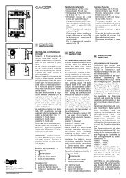
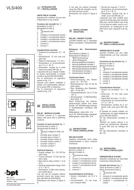
UNITA’ RELE’ <strong>VLS</strong>/<strong>400</strong><br />
Apparecchio costituito da due relé<br />
indipendenti a due scambi.<br />
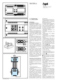
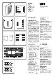
Funzione dei morsetti (fig. 1)<br />
Morsettiera A (relé 1)<br />
Morsettiera B (relé 2)<br />
1 + comando relé<br />
2 –<br />
3 contatto 2 normalmente aperto<br />
4 contatto 1 normalmente aperto<br />
5 contatto 2 normalmente chiuso<br />
6 contatto 1 normalmente chiuso<br />
7 comune 2<br />
8 comune 1<br />
Caratteristiche tecniche<br />
•Tensione di eccitazione: 10 ÷ 18<br />
Vcc.<br />
• Assorbimento: 15 mA max per<br />
ogni relé.<br />
• Potere di interruzione: 1 A, 24 V.<br />
•Temperatura di funzionamento:<br />
da 0 °C a + 35 °C.<br />
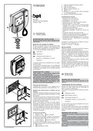
• Dimensioni: modulo da 4 unità<br />
basso per guida DIN (fig. 2).<br />
L’apparecchio può essere installato,<br />
senza coprimorsetti, in scatole<br />
munite di guida DIN (EN 50022).<br />
Per le dimensioni di ingombro<br />
vedere la fig. 2 A.<br />
Oppure può essere installato a<br />
parete, con coprimorsetti, utilizzando<br />
la guida DIN in dotazione.<br />
Per le dimensioni di ingombro<br />
vedere la fig. 2 B.<br />
GB INSTALLATION<br />
INSTRUCTIONS<br />
RELAY - MODULE <strong>VLS</strong>/<strong>400</strong><br />
<strong>VLS</strong>/<strong>400</strong> consist of 2 separate<br />
relays coils each with 2 switching<br />
contacts.<br />
Function of each terminal (fig. 1)<br />
Terminal block A (relay 1)<br />
Terminal block B (relay 2)<br />
1 + supply voltage to relay coil<br />
2 –<br />
3 normally open contact 2<br />
4 normally open contact 1<br />
5 normally closed contact 2<br />
6 normally closed contact 1<br />
7 common contact 2<br />
8 common contact 1<br />
Technical features<br />
• Supply voltage: 10 ÷ 18 V DC for<br />
each relay.<br />
• Current demand: 15 mA max for<br />
each relay.<br />
•Max load to relay contact: 1 A at<br />
24 V.<br />
•Working temperature range: from<br />
0 °C + 35 °C.<br />
• Dimensions: 4 DIN units module,<br />
low profile (fig.2).<br />
The unit can be installed without<br />
terminal covers into boxes provided<br />
with DIN rail (EN 50022).<br />
Dimensions are shown in figure 2<br />
A.<br />
It can also be surface mounted,<br />
using the DIN rail supplied, but fitted<br />
with terminal covers.<br />
Dimensions are shown in figure 2<br />
B.<br />
D INSTALLATIONS-<br />
ANLEITUNG<br />
RELAIS - EINHEIT <strong>VLS</strong>/<strong>400</strong><br />
<strong>VLS</strong>/<strong>400</strong> besteht aus 2 separaten<br />
Relais mit jeweils 2 Doppelkontakten.<br />
Belegung der Klemmleisten<br />
(Abb.1)<br />
Klemmleiste A (Relais 1)<br />
Klemmleiste B (Relais 2)<br />
1 + Stromversorgung<br />
2 – der Relaisspule<br />
3 Normal geöffneter Kontakt 2<br />
4 Normal geöffneter Kontakt 1<br />
5 Normal geschlossener Kontakt 2<br />
6 Normal geschlossener Kontakt 1<br />
7 Gemeinsamer Kontakt 2<br />
8 Gemeinsamer Kontakt 1<br />
Technische Daten<br />
• Stromversorgung der Relaisspule:<br />
10 ÷ 18 V DC.<br />
• Stromaufnahme: max 15 mA für<br />
jeder relais.<br />
• Max. Belastung des Relaiskontakt:<br />
1 A bei 24 V.<br />
•Temperaturbereich: von 0 °C bis<br />
+35 °C.<br />
• Abmessungen: 4 DIN-Einheiten,<br />
flach (Abb. 2).<br />
Nach Entfernung der Klemmabdeckungen<br />
lassen sich diese<br />
Geräte auf DIN-Montageschienen<br />
in Verteilerkästen montieren (EN<br />
50022).<br />
Maßangaben, siehe Abb. 2 A.<br />
Auch für Wandmontage geeignet.<br />
Maßangaben, siehe Abb. 2 B.<br />
F INSTRUCTIONS<br />
POUR L’INSTALLATION<br />
RELAIS <strong>VLS</strong>/<strong>400</strong><br />
Appareil comportant deux relais<br />
indépendantes à deux contacts<br />
inverseurs.<br />
Fonction des bornes (fig. 1)<br />
Bornier A (relais 1)<br />
Bornier B (relais 2)<br />
1 + commande relais<br />
2 –<br />
3 contact 2 normalement ouvert<br />
4 contact 1 normalement ouvert<br />
5 contact 2 normalement fermé<br />
6 contact 1 normalement fermé<br />
7 commun 2<br />
8 commun 1<br />
Caractéristiques techniques<br />
•Tension d’excitation: de 10 V à<br />
18 Vcc.<br />
• Consommation: 15 mA maxi<br />
pour chaque relais.<br />
• Pouvoir de coupure: 1 A 24 V.<br />
•Température de fonctionnement:<br />
de 0 °C à + 35 °C.<br />
• Dimensions: module bas de 4<br />
unités pour rail DIN (fig. 2).<br />
L’appareil peut être installé sans<br />
couvre-borniers dans des armoires<br />
DIN avec rail EN 50022 (voir la fig<br />
2 A) ou bien en saillie, avec le couvre-borniers,<br />
en employant le rail<br />
DIN fourni avec l’appareil (voir fig.<br />
2 B).<br />
E INSTRUCCIONES<br />
PARA LA INSTALACION<br />
UNIDAD-RELE <strong>VLS</strong>/<strong>400</strong><br />
Aparato formado por dos relés<br />
indipendientes con dos conmutaciones.<br />
Funciones de los bornes (fig. 1)<br />
Bornera A (relé 1)<br />
Bornera B (relé 2)<br />
1 + mando relé<br />
2 –<br />
3 contacto 2 normalmente abierto<br />
4 contacto 1 normalmente abierto<br />
5 contacto 2 normalmente cerrado<br />
6 contacto 1 normalmente cerrado<br />
7 común 2<br />
8 común 1<br />
Características técnicas<br />
•Tensión de excitatión: 10 ÷ 18<br />
Vcc.<br />
• Absorción: 15 mA máx para<br />
cada relé.<br />
• Capacidad de corte: 1 A, 24 V<br />
•Temperatura de funcionamiento:<br />
0 °C a + 35 °C.<br />
• Dimensiones: módulo de 4 unidades<br />
bajo para guía DIN (fig.<br />
2).<br />
El aparato se puede instalar, sin<br />
cubrebornes, en cajas dotadas de<br />
guías DIN (EN 50022).<br />
Por las dimensiones consultar la<br />
fig. 2 A.<br />
También se puede aplicar a la<br />
pared con cubrebornes, utilizando<br />
la guía DIN que se entrega de<br />
serie.<br />
Por las dimensiones consultar la<br />
fig. 2 B.<br />
P INSTRUÇÕES<br />
PARA A INSTALAÇÃO<br />
UNIDADE-RELE <strong>VLS</strong>/<strong>400</strong><br />
Aparelho constituído por dois relés<br />
inversores independentes.<br />
Função dos bornes (fig. 1)<br />
Placa de bornes A (relé 1)<br />
Placa de bornes B (relé 2)<br />
1 +<br />
comando relé<br />
2 –<br />
3 contacto 2 normalmente aberto<br />
4 contacto 1 normalmente aberto<br />
5 contacto 1 normalmente fechado<br />
1
6 contacto 1 normalmente fechado<br />
7 comum 2<br />
8 comum 1<br />
Características técnicas<br />
•Tensão de funcionamento: 10 ÷<br />
18 Vcc.<br />
• Consumo: 15 mA max para cada<br />
relé.<br />
• Poder de corte: 1 A, 24 V com<br />
carga resistiva.<br />
•Temperatura de funcionamento:<br />
de 0 °C a + 35 °C.<br />
• Dimensões: módulo de 4 unidades<br />
baixo para calha DIN (fig.<br />
2).<br />
O aparelho pose ser instalado,<br />
sem a tampa dos bornes, em<br />
caixas com calha DIN (EN 50022).<br />
Para as dimensões ver fig. 2 A.<br />
Também se pode aplicar na parede<br />
com a tampas dos bornes, utilizando<br />
calha DIN fornecida de<br />
série.<br />
Para as dimensões ver fig. 2 B.<br />
2<br />
21<br />
A/200<br />
A/241<br />
XC/200-C/200<br />
C/241(E/220)<br />
C<br />
5 (1)<br />
<strong>VLS</strong>/<strong>400</strong><br />
A<br />
1<br />
2<br />
3<br />
4<br />
5<br />
6<br />
7<br />
8<br />
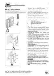
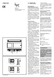
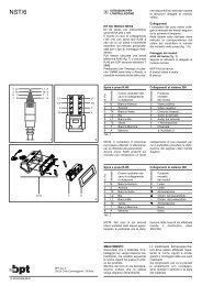
Fig. 3 - Schema di collegamento<br />
comando luce scale, apriporta<br />
supplementare, ecc. tramite il pulsante<br />
ausiliario del citofono e unitàrelé<br />
<strong>VLS</strong>/<strong>400</strong>.<br />
Fig. 3 - Wiring diagram for stair<br />
light and supplementary door<br />
release etc. controlled from auxiliary<br />
button on handset and<br />
<strong>VLS</strong>/<strong>400</strong> relay unit.<br />
Abb. 3 - Anschlußplan für die<br />
Steuerung von Treppenbeleuchtung,<br />
zusätzlichem Türöffner über<br />
die Zusatztaste der Sprechgarnitur<br />
und die Relaiseinheit <strong>VLS</strong>/<strong>400</strong>.<br />
Fig. 3 - Schéma de branchement<br />
commande minuterie, ouvre-porte<br />
supplémentaire, etc. par le bouton<br />
auxiliaire du combiné et le relais<br />
<strong>VLS</strong>/<strong>400</strong>.<br />
Fig. 3 - Esquema de conexión<br />
para el mando de luz de la escalera,<br />
abrepuerta suplementario, etc.,<br />
mediante el pulsador auxiliar del<br />
teléfono y la unidad-relé <strong>VLS</strong>/<strong>400</strong>.<br />
Fig. 3 - Esquema de ligação do<br />
comando da luz de escadas, abertura<br />
de porta suplementar, etc.<br />
através do botão auxiliar do telefone<br />
e o relé <strong>VLS</strong>/<strong>400</strong>.<br />
3<br />
5 6<br />
VA/200<br />
C/200<br />
C<br />
5<br />
7<br />
8<br />
9<br />
VM/200 (VM/203)<br />
A<br />
3<br />
4<br />
5<br />
6<br />
7<br />
8<br />
9<br />
10<br />
11<br />
12<br />
13<br />
14<br />
15<br />
16<br />
17<br />
18<br />
19<br />
20<br />
<strong>VLS</strong>/<strong>400</strong><br />
1<br />
2<br />
3 45678<br />
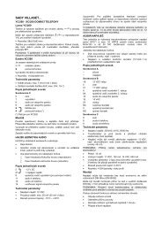
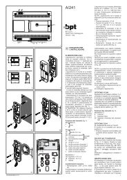
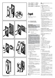
Fig. 4 - Schema di collegamento<br />
del comando apriporta supplementare,<br />
o altro servizio, tramite il<br />
pulsante ausiliario del derivato<br />
interno (C/200, VM/200) e l’unitàrelé<br />
<strong>VLS</strong>/<strong>400</strong>.<br />
Fig. 4 - Wiring diagram for supplementary<br />
door release etc. controlled<br />
from receiver auxiliary button<br />
(C/200, VM/200) and <strong>VLS</strong>/<strong>400</strong><br />
relay unit.<br />
Abb. 4 - Anschlußplan für den<br />
zusätzlichem Türöffner oder eine<br />
andere Funktion über die Zusatztaste<br />
der internen Sprechstelle<br />
(C/200, VM/200) und Relaiseinheit<br />
<strong>VLS</strong>/<strong>400</strong>.<br />
Fig. 4 - Schéma de branchement<br />
de la commande ouvre-porte supplémentaire,<br />
ou autre service, par<br />
le bouton auxiliaire du poste intérieur<br />
(C/200, VM/200) et le relais<br />
<strong>VLS</strong>/<strong>400</strong>.<br />
Fig. 4 - Esquema de conexión del<br />
mando abrepuerta suplementario,<br />
o de otro servicio, mediante el pulsador<br />
auxiliar del derivado interno<br />
(C/200, VM/200) y la unidad-relé<br />
<strong>VLS</strong>/<strong>400</strong>.<br />
Fig. 4 - Esquema de ligação do<br />
comando da luz de escadas, abertura<br />
de porta suplementar, etc.<br />
através do botão auxiliar do telefone,<br />
monitor (C/200, VM/200) e o<br />
relé <strong>VLS</strong>/<strong>400</strong>.<br />
2<br />
1<br />
4<br />
56<br />
VA/200<br />
XC/200<br />
C<br />
5 7<br />
8<br />
9<br />
XV/200+XC/200<br />
3<br />
4<br />
5<br />
6<br />
7<br />
8<br />
9<br />
20<br />
E<br />
C XC/200<br />
CN/2<br />
5<br />
<strong>VLS</strong>/<strong>400</strong><br />
A<br />
1<br />
2<br />
3<br />
45678<br />
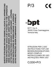
Fig. 5 - Schema di collegamento<br />
del comando apriporta supplementare,<br />
o altro servizio, tramite il<br />
pulsante ausiliario del derivato<br />
interno (XC/200, XV/200) e l’unitàrelé<br />
<strong>VLS</strong>/<strong>400</strong>.<br />
Fig. 5 - Wiring diagram for supplementary<br />
door release etc. controlled<br />
from receiver auxiliary button<br />
(XC/200, XV/200) and <strong>VLS</strong>/<strong>400</strong><br />
relay unit.<br />
Abb. 5 - Anschlußplan für den<br />
zusätzlichem Türöffner oder eine<br />
andere Funktion über die Zusatztaste<br />
der internen Sprechstelle<br />
(XC/200, XV/200) und Relaiseinheit<br />
<strong>VLS</strong>/<strong>400</strong>.<br />
Fig. 5 - Schéma de branchement<br />
de la commande ouvre-porte supplémentaire,<br />
ou autre service, par<br />
le bouton auxiliaire du poste intérieur<br />
(XC/200, XV/200) et le relais<br />
<strong>VLS</strong>/<strong>400</strong>.<br />
Fig. 5 - Esquema de conexión del<br />
mando abrepuerta suplementario,<br />
o de otro servicio, mediante el pulsador<br />
auxiliar del derivado interno<br />
(XC/200, XV/200) y la unidad-relé<br />
<strong>VLS</strong>/<strong>400</strong>.<br />
Fig. 5 - Esquema de ligação do<br />
comando da luz de escadas, abertura<br />
de porta suplementar, etc.<br />
através do botão auxiliar do telefone,<br />
monitor (XC/200, XV/200) e o<br />
relé <strong>VLS</strong>/<strong>400</strong>.<br />
2<br />
1<br />
5