MVA-MVT100 2403-1700 01.04 - TECH FASS sro
MVA-MVT100 2403-1700 01.04 - TECH FASS sro
MVA-MVT100 2403-1700 01.04 - TECH FASS sro

You also want an ePaper? Increase the reach of your titles
YUMPU automatically turns print PDFs into web optimized ePapers that Google loves.
SW3<br />
2<br />
1<br />
01.2004/<strong>2403</strong>-<strong>1700</strong><br />
SW2<br />
2<br />
1<br />
1<br />
2<br />
ALTO<br />
TOP<br />
OBEN<br />
HAUT<br />
2<br />
4 5<br />
6<br />
7<br />
3<br />
5<br />
R<br />
M<br />
1<br />
ALTO<br />
TOP<br />
OBEN<br />
HAUT<br />
2<br />
1<br />
3<br />
7<br />
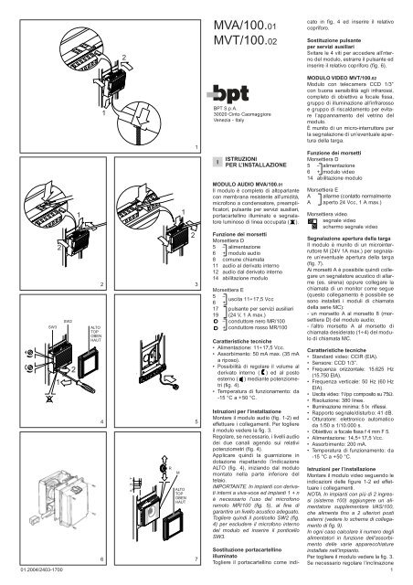
<strong>MVA</strong>/100.01<br />
MVT/100.02<br />
BPT S.p.A.<br />
30020 Cinto Caomaggiore<br />
Venezia - Italy<br />
I<br />
ISTRUZIONI<br />
PER L’INSTALLAZIONE<br />
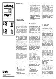
MODULO AUDIO <strong>MVA</strong>/100.01<br />
Il modulo è completo di altoparlante<br />
con membrana resistente all’umidità,<br />
microfono a condensatore, preamplificatori,<br />
pulsante per servizi ausiliari,<br />
portacartellino illuminato e segnalatore<br />
luminoso di linea occupata ( ).<br />
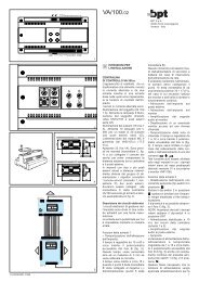
Funzione dei morsetti<br />
Morsettiera D<br />
5 – alimentazione<br />
6 + modulo audio<br />
8 comune chiamata<br />
11 audio al derivato interno<br />
12 audio dal derivato interno<br />
14 abilitazione modulo<br />
Morsettiera E<br />
5 – uscita 11÷17,5 Vcc<br />
6 +<br />
17 pulsante per servizi ausiliari<br />
19 (24 V, 1 A max.)<br />
– conduttore nero MR/100<br />
+ conduttore rosso MR/100<br />
Caratteristiche tecniche<br />
• Alimentazione: 11÷17,5 Vcc.<br />
• Assorbimento: 50 mA max. (35 mA<br />
a riposo).<br />
• Possibilità di regolare il volume al<br />
derivato interno ( ) ed al posto<br />
esterno ( ) mediante potenziometri<br />
(fig. 4).<br />
•Temperatura di funzionamento: da<br />
-15 °C a +50 °C.<br />
Istruzioni per l’installazione<br />
Montare il modulo audio (fig. 1-2) ed<br />
effettuare i collegamenti. Per togliere<br />
il modulo vedere la fig. 3.<br />
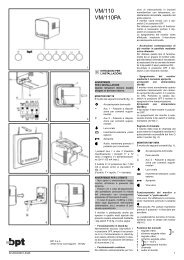
Regolare, se necessario, i livelli audio<br />
dei due canali agendo sui relativi<br />
potenziometri (fig. 4).<br />
Applicare quindi la guarnizione in<br />
dotazione rispettando l’indicazione<br />
ALTO (fig. 4), iniziando dal modulo<br />
montato nella parte inferiore del<br />
telaio.<br />
IMPORTANTE. In impianti con derivati<br />
interni a viva-voce ed impianti 1 + n<br />
è necessario l’uso del microfono<br />
remoto MR/100 (fig. 5), al fine di<br />
garantire un livello acustico adeguato.<br />
Togliere quindi il ponticello SW2 (fig.<br />
4) per escludere il microfono interno<br />
del modulo ed inserire il ponticello<br />
SW3.<br />
Sostituzione portacartellino<br />
illuminato<br />
Togliere il portacartellino come indi-<br />
cato in fig. 4 ed inserire il relativo<br />
copriforo.<br />
Sostituzione pulsante<br />
per servizi ausiliari<br />
Svitare le 4 viti per accedere all’nterno<br />
del modulo, estrarre il pulsante ed<br />
inserire il relativo copriforo (fig. 6).<br />
MODULO VIDEO MVT/100.02<br />
Modulo con telecamera CCD 1/3”<br />
con buona sensibilità agli infrarossi,<br />
completo di obiettivo a focale fissa,<br />
gruppo di illuminazione all’infrarosso<br />
e gruppo di riscaldamento per evitare<br />
l’appannamento del vetrino del<br />
modulo.<br />
È munito di un micro-interruttore per<br />
la segnalazione di un’eventuale apertura<br />
della targa.<br />
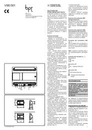
Funzione dei morsetti<br />
Morsettiera D<br />
5 – alimentazione<br />
6 + modulo video<br />
14 abilitazione modulo<br />
Morsettiera E<br />
A allarme (contatto normalmente<br />
A aperto 24 Vcc, 1 A max.)<br />
Morsettiera video<br />
segnale video<br />
schermo segnale video<br />
Segnalazione apertura della targa<br />
Il modulo è munito di un microinterruttore<br />
M (24V 1A max.) per segnalare<br />
un’eventuale apertura della targa<br />
(fig. 7).<br />
Ai morsetti A è possibile quindi collegare<br />
un segnalatore acustico di allarme<br />
(es. sirena) oppure collegare la<br />
chiamata di un monitor come segue<br />
(questo collegamento è possibile se<br />
sono installati i moduli di chiamata<br />
della serie MC):<br />
- un morsetto A al morsetto 8 (morsettiera<br />
D) del modulo audio;<br />
- l’altro morsetto A al morsetto di<br />
chiamata desiderato (1÷4) del modulo<br />
di chiamata MC.<br />
Caratteristiche tecniche<br />
• Standard video: CCIR (EIA).<br />
• Sensore: CCD 1/3”.<br />
•Frequenza orizzontale: 15.625 Hz<br />
(15.750 EIA).<br />
•Frequenza verticale: 50 Hz (60 Hz<br />
EIA).<br />
• Uscita video: 1Vpp composito su 75Ω.<br />
• Risoluzione: 380 linee.<br />
• Illuminazione minima: 5 lx riflessi.<br />
•Rapporto segnale/disturbo: 41 dB.<br />
• Otturatore: elettronico automatico<br />
da 1/50 a 1/10.000 s.<br />
• Obiettivo: a focale fissa f 4 mm F 5.<br />
• Alimentazione: 14,5÷17,5 Vcc.<br />
• Assorbimento: 200 mA.<br />
•Temperatura di funzionamento: da<br />
-15 °C a +50 °C.<br />
Istruzioni per l’installazione<br />
Montare il modulo video seguendo le<br />
indicazioni delle figure 1-2 ed effettuare<br />
i collegamenti.<br />
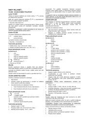
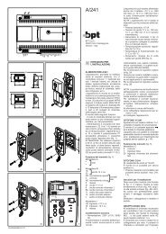
NOTA. In impianti con più di 2 ingressi<br />
(sistema 100) aggiungere un alimentatore<br />
supplementare VAS/100,<br />
che alimenta fino a 2 ulteriori posti<br />
esterni (vedere lo schema di collegamento<br />
di fig. 9).<br />
In ogni caso calcolare il numero degli<br />
alimentatori in funzione dell’assorbimento<br />
delle varie apparecchiature<br />
installate nell’impianto.<br />
Per togliere il modulo vedere la fig. 3.<br />
Se necessario regolare l’inclinazione<br />
1
della telecamera agendo sulla vite R<br />
come indicato in fig. 7.<br />
Applicare quindi la guarnizione in<br />
dotazione rispettando l’indicazione<br />
ALTO (fig. 4), iniziando dal modulo<br />
montato nella parte inferiore del<br />
telaio.<br />
GB INSTALLATION<br />
INSTRUCTIONS<br />
<strong>MVA</strong>/100.01 AUDIO MODULE<br />
It is supplied complete with loudspeaker<br />
- protected against elements<br />
by a diaphragm - condenser micro-<br />
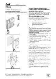
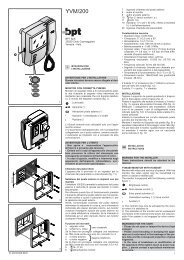
DIMENSIONI DELLA ZONA DI RIPRE-<br />
SA DELL’OTTICA IN DOTAZIONE<br />
FIELD OF VIEW<br />
OF LENS SUPPLIED<br />
BRENNWEITEN DER MITGELIEFER-<br />
TEN OBJEKTIVE<br />
Lunghezza focale f mm<br />
Luminosità F<br />
Focal lenght f (mm)<br />
Brightness F<br />
Brennweite f (mm)<br />
Helligkeit F<br />
Longueur focale f (mm)<br />
Luminosité F<br />
Longitud focal f (mm)<br />
Luminosidad F<br />
Comprimento focal f (mm)<br />
Luminosidade F<br />
2<br />
Angolo<br />
di visione<br />
Angle<br />
of view<br />
Aufnahmewinkel<br />
Angle de<br />
prise de vue<br />
Angulo<br />
de vision<br />
phone, pre-amplifier, push-button for<br />
auxiliary service as required, illuminated<br />
card-name, and system engaged<br />
indicator ( ).<br />
Function of each terminal<br />
Terminal block D<br />
5 – supply voltage to<br />
6 + audio module<br />
8 call common<br />
11 audio to receiver<br />
12 audio from receiver<br />
14 enabling module<br />
Terminal block E<br />
5 – 11÷17.5 V DC output<br />
6 +<br />
17 button for any other services<br />
19 as required (24 V, 1 A max.)<br />
– black wire of MR/100<br />
+red wire of MR/100<br />
ZONE DE PRISE DE VUE<br />
DU OBJECTIF DE BASE<br />
DIMENSIONES DEL CAMPO DE AC-<br />
CION DE LA OPTICA SUMINISTRADA<br />
DIMENSÕES DA ZONA DE FILMA-<br />
GEM DA OPTICA FORNECIDA<br />
Distanza (d) - Distance (d)<br />
Entfernung (d) - Distance (d)<br />
Distancia (d) - Distância (d)<br />
α<br />
β<br />
Ângulo<br />
de visão 1 m 2 m 4 m 6 m 8 m 10 m<br />
f 4 F 5 α 61° 54’ b 1,2 2,4 4,8 7,2 9,6 12<br />
β 48° 26’ h 0,9 1,8 3,6 5,4 7,2 9<br />
TTS/...+ 12V<br />
TMP/...+<br />
<strong>MVA</strong>/100+<br />
MVT/100.02+<br />
AE<br />
MC/...<br />
<strong>MVA</strong>/100<br />
5<br />
6<br />
8<br />
11<br />
12<br />
14<br />
D<br />
E<br />
5<br />
6<br />
17<br />
19<br />
-<br />
+<br />
MVT/100<br />
MC/...<br />
5<br />
6<br />
14<br />
A<br />
A<br />
C 1234<br />
D<br />
E<br />
16<br />
15<br />
14<br />
R<br />
11<br />
12<br />
13<br />
14<br />
15<br />
16<br />
13<br />
12<br />
11<br />
10<br />
98765<br />
b<br />
4<br />
3<br />
21<br />
15<br />
14<br />
13<br />
12<br />
11<br />
10<br />
9<br />
8<br />
7<br />
6<br />
5<br />
4<br />
3<br />
21<br />
16 1 2345678910<br />
VA/100<br />
(VSI/120)<br />
VSI/110<br />
d<br />
S<br />
P<br />
h<br />
Q<br />
1<br />
2<br />
3<br />
4<br />
5<br />
6<br />
7<br />
8<br />
9<br />
10<br />
11<br />
12<br />
13<br />
14<br />
15<br />
16<br />
8<br />
VSI/120<br />
Technical features<br />
• Supply voltage: 11÷17.5 V DC.<br />
• Current demand: 50 mA max (35<br />
mA quiescent).<br />
• Potentiometers to regulate audio<br />
volume to receiver ( ) and entry<br />
panel ( ), figure 4.<br />
•Working temperature range: from -15<br />
°C to +50 °C.<br />
Installation instructions<br />
Fit the audio module (see figures 1-2)<br />
and connect the wires.<br />
Remove the module as shown in figure<br />
3.<br />
If necessary regulate the audio level<br />
of both channel using potentiometer<br />
indicated in figure 4.<br />
Then fit the seal supplied, making<br />
certain that the side marked TOP<br />
faces upwards, figure 4; start fitting<br />
the seal from the module at the bottom<br />
of the chassis.<br />
WARNING. It is required to use the<br />
microphone MR/100, figure 5, in<br />
installations using receivers without<br />
handset and in 1 + n installations, to<br />
provide adeguate audio volume.<br />
Remove SW2 link, figure 4, to isolate<br />
audio module microphone and insert<br />
the SW3 link.<br />
Replacing the light<br />
card-name holder<br />
Take the card-name holder away as<br />
indicated in figure 5 and insert the<br />
corresponding hole-cover.<br />
Replacing the push-button<br />
for auxiliary services<br />
Unscrew the 4 screws to have access<br />
to the inside of the module, remove the<br />
push-button and insert the corresponding<br />
hole-cover, figure 6.<br />
MVT/100.02 CAMERA MODULE<br />
Module with 1/3” CCD camera with<br />
fix focal lens and good sensitivity to<br />
infrared illumination.<br />
Camera is supplied complete with<br />
infrared illumination unit and heating<br />
A<br />
VAS/100<br />
12V<br />
<strong>MVA</strong>/100<br />
5<br />
6<br />
8<br />
11<br />
12<br />
14<br />
D<br />
E<br />
5<br />
6<br />
17<br />
19<br />
D<br />
E<br />
1<br />
2<br />
1<br />
2<br />
5<br />
6<br />
14<br />
-<br />
+<br />
MVT/100<br />
C 1234<br />
TTS/...+<br />
TMP/...+<br />
<strong>MVA</strong>/100+<br />
MVT/100.02+<br />
AE<br />
MC/...<br />
A A<br />
MC/...<br />
9<br />
unit to avoid misting of the module<br />
window glass.<br />
The camera module is equipped with<br />
a microswitch that can be used to<br />
generate an alarm signal to detect<br />
any attempt to interfere with panel.<br />
Function of each terminal<br />
Terminal block D<br />
5 – supply voltage to camera<br />
6 +<br />
14 enabling module<br />
Terminal block E<br />
A alarm (normally open<br />
A contact 24 V DC, 1 A max.)<br />
Video terminal block<br />
video signal<br />
video signal shield<br />
Protection against<br />
manipulations<br />
The camera module is equipped with a<br />
microswitch M (max. current load 1A at<br />
24V) that can be used to generate an<br />
alarm signal to detect any attempt to<br />
interfere with panel, figure 7.<br />
It is possible to connect to terminals<br />
A an acoustic device (e.g. siren) or,<br />
as indicated below, the call signal<br />
that activate a monitor (this connection<br />
is possible if are installed the<br />
call module series MC):<br />
- one terminal A of block E to terminal<br />
8 block D of audio module;<br />
-the other terminal to the desired call<br />
button terminal of MC call module.<br />
Technical features<br />
• CCIR (EIA) standard.<br />
• Pick-up device: 1/3” CCD sensor.<br />
• Horizontal frequency: 15,625 Hz<br />
(15,750 EIA).<br />
•Vertical frequency: 50 Hz (60 Hz EIA).<br />
•Video signal output: 1Vpp composite<br />
interlaced to 75 Ω.<br />
• Resolution: 380 lines.<br />
• Minimum illumination: 5 lx.<br />
• Ratio signal/noise: 41 dB.<br />
• Shutter: electronic control from 1/50<br />
to 1/10,000 s.<br />
• Fix focal lens: lenght f 4 mm, brightness<br />
F 5.<br />
• Supply voltage: 14.5 ÷ 17.5 V DC.<br />
• Current demand: 200 mA.<br />
•Working temperature range: from -15<br />
°C to +50 °C.<br />
Installation instructions<br />
Fit the camera module as shown in<br />
figures 1-2 and connect the wires.<br />
NOTE. In installations (system 100)<br />
with more than 2 entrances a supplementary<br />
VAS/100 power supplier is<br />
needed to feed a maximum of 4 additional<br />
entry panels (see connection<br />
diagram in figure 9).<br />
Always calculate the number of power<br />
suppliers to suit the power requirements<br />
of the various items of equipment<br />
in the system.<br />
Remove the module as shown in figure<br />
3.<br />
If necessary, tilt the camera by operating<br />
on the screw R as indicated on<br />
fig. 7.<br />
Then fit the seal supplied, making<br />
certain that the side marked TOP<br />
faces upwards, figure 7; start fitting<br />
the seal from the module at the bottom<br />
of the chassis.
D INSTALLATIONS-<br />
ANLEITUNG<br />
TÜRLAUTSPRECHERMODUL<br />
<strong>MVA</strong>/100.01<br />
Das Modul umfaßt einen Lautsprecher<br />
mit feuchtigkeitsbeständiger<br />
Membran, Kondensator-Mikrofon,<br />
Vorverstärkern, Taste für Zusatzgeräte,<br />
beleuchteter Schildhalter und<br />
Leuchtanzeige Leitung besetzt ( ).<br />
Belegung der Klemmleisten<br />
Klemmleiste D<br />
5 – Stromversorgung<br />
6 + Lautsprecher-Modul<br />
8 Gemeinsamer Anruf<br />
11 Audio zur Sprechgarnitur<br />
12 Audio von der Sprechgarnitur<br />
14 Steuersignal Modul<br />
Klemmleiste E<br />
5 – 11÷17,5 V DC Ausgang<br />
6 +<br />
17 Tasten für zusätzlicher<br />
19 Service (24 V, 1 A max.)<br />
– Schwarzer Leiter MR/100<br />
+ Roter Leiter MR/100<br />
Technische Daten<br />
• Stromversorgung: 11÷17,5 V DC.<br />
• Stromaufnahme: 50 mA max. (35<br />
mA Ruhestrom).<br />
• Möglichkeit der Lautstärkeregelung<br />
an der Sprechgarnitur ( ) und an<br />
der Außenstation ( ) durch Potentiometer<br />
(Abb. 4).<br />
• Betriebstemperatur: von -15 °C bis<br />
+50 °C.<br />
Installationsanleitung<br />
Das Türlautsprechermodul montieren<br />
(siehe Abb. 1-2) und die Anschlüsse<br />
ausführen.<br />
Um das Modul herauszuziehen siehe<br />
Abb. 3. Falls erforderlich, den<br />
Lautstärkepegel der beiden Kanäle<br />
über die entsprechenden Potentiometer<br />
regulieren (Abb. 4).<br />
Danach die mitgelieferte Dichtung<br />
aufsetzen.<br />
Hierbei auf die Aufschrift OBEN<br />
(Abb. 4) achten und mit dem Modul<br />
beginnen, das sich im unteren Teil<br />
des Chassis befindet.<br />
WICHTIG. Bei Anlagen mit internen<br />
Sprechstellen mit Freihandbetrieb<br />
und bei Anlagen 1+n ist das<br />
Fernmikrofon MR/100 (Abb. 5) zur<br />
Gewährleistung einer angemessenen<br />
Lautstärke erforderlich.<br />
Die Brücke SW2 (Abb. 4) entfernen,<br />
um das eingebaute Mikrofon auszuschließenund<br />
Brücke SW3 entschalten.<br />
Beleuchtetes Namenschildhalter<br />
Ersatz<br />
Namenschildhalter entfernen wie in<br />
Abb. 4 und dazugehörende Verschlußknopf<br />
anbringen.<br />
Hilfsdiensttaste Ersatz<br />
Die 4 Schrauben lösen für Zugang zu<br />
den Moduleraum, Tasten entfernen<br />
und dazugehörende Verschlußknopf<br />
anbringen (Abb. 6).<br />
MVT/100.02 KAMERA<br />
Modul mit CCD-Aufnahmeeinheit mit<br />
guter Empfindlichkeit gegenüber<br />
Infrarotstrahlen, komplett mit Objektiv<br />
mit fester Brennweite und Infrarotstrahlplatine<br />
und Heizeinheit um das<br />
Beschlagen des Kamerafensters zu<br />
vermeiden.<br />
Das Kameramodul ist mit einem<br />
Mikroschalter ausgestattet der bei<br />
Abnahme des Tableaus ein Alarmsignal<br />
schalten kann.<br />
Belegung der Klemmleisten<br />
Klemmleiste D<br />
5 – Kameraversorgung<br />
6 +<br />
14 Steuersignal Modul<br />
Klemmleiste E<br />
A Alarmsensor (normal geöffne-<br />
A ter Kontakt 24 V, 1 A max.)<br />
Videoklemmleiste<br />
Videosignal<br />
Videosignalabschirmung<br />
Schutz gegen Manipulation<br />
Das Kameramodul ist mit einem<br />
Mikroschalter M ausgestattet (max.<br />
1A, 24V) der bei Abnahme des<br />
Tableaus ein Alarmsignal schalten<br />
kann (Abb. 7).<br />
Über Klemme A kann ein externes<br />
Alarmgerät (z.B. Sirene) angeschlossen<br />
werden oder wie unten angegeben<br />
ein Rufsignal über den Monitor<br />
geschaltet werden (Diese Schaltung<br />
ist möglich, wenn die Rufmodule<br />
der Serie MC installiert werden):<br />
- erste Klemme A zu Klemme 8<br />
(Klemmleiste D) der Audiomodul.<br />
- zweite Klemme A zu der Rufklemme<br />
(1÷4 des Rufmoduls MC) bezogen<br />
auf den gewünschten Monitor.<br />
Technische Daten<br />
• CCIR (EIA) Standard.<br />
• Bildsensor: 1/3” CCD.<br />
• Horizontalfrequenz: 15.625 Hz<br />
(15.750 EIA).<br />
•Vertikalfrequenz: 50 Hz (60 Hz<br />
EIA).<br />
•Videosignalausgang: mit Schnittstelle,<br />
1Vpp auf 75 Ω.<br />
• Auflösung: 380 Linien.<br />
• Mindestbeleuchtung: 5 lx.<br />
• Rauschabstand: 41 dB.<br />
• Shutter: elektronisch von 1/50 bis<br />
1/10.000 s.<br />
• Festobjektiv: f 4 mm F 5.<br />
• Stromversorgung: 14,5÷17,5V DC.<br />
• Stromaufnahme: 200mA.<br />
• Betriebstemperatur: von -15 °C bis<br />
+50 °C.<br />
Installationsanleitung<br />
Das Kameramodul montieren (siehe<br />
Abbildungen 1-2) und die Anschlüsse<br />
ausführen.<br />
ANMERKUNG. An Anlagen (System<br />
100) mit mehr als 2 Eingängen ist ein<br />
zusätzlicher Netzgerät VAS/100 erforderlich,<br />
der bis zu 4 weitere Außenstationen<br />
versorgt (siehe Schaltbild für<br />
den Anschluß in Abb. 9).<br />
Die Anzahl der erforderlichen Netzgeräte<br />
anhand der Aufnahme der verschiedenen<br />
Anlagengeräte ermitteln.<br />
Um das Modul herauszuziehen siehe<br />
Abb. 3. Wenn notwending, die<br />
Schraube R (Abb. 7) drehen um die<br />
Kamera in die richtige Position zu<br />
bringen.<br />
Danach die mitgelieferte Dichtung<br />
aufsetzen.<br />
Hierbei auf die Aufschrift OBEN<br />
(Abb. 7) achten und mit dem Modul<br />
beginnen, das sich im unteren Teil<br />
des Chassis befindet.<br />
F INSTRUCTIONS<br />
POUR L’INSTALLATION<br />
MODULE AUDIO <strong>MVA</strong>/100.01<br />
Le module est complété de haut-parleur<br />
avec membrane résistant à l’humidité,<br />
microphone à condensateur,<br />
pré-amplificateurs, bouton-poussoir<br />
pour services auxiliaires, porte-platine<br />
éclairé et dispositif de signalisation<br />
de ligne occupée lumineux ( ).<br />
Fonction des bornes<br />
Bornier D<br />
5 – alimentation module audio<br />
6 +<br />
8 commun appel<br />
11 audio au poste intérieur<br />
12 audio depuis le poste intérieur<br />
14 activation modul<br />
Bornier E<br />
5 – sortie 11÷17,5 Vcc<br />
6 +<br />
17 bouton-poussoir pour services<br />
19 auxiliaires (24 V, 1 A maxi)<br />
– conducteur noir du MR/100<br />
+ conducteur rouge du MR/100<br />
Caractéristiques techniques<br />
• Alimentation: 11÷17,5 Vcc.<br />
• Consommation: 50 mA maxi (35<br />
mA à repos).<br />
• Possibilité de régler le volume au<br />
niveau du poste intérieur ( ) et du<br />
poste extérieur ( ) a moyen des<br />
potentiomètres.<br />
•Température de fonctionnement:<br />
de -15 °C à +50 °C.<br />
Instructions d’installation<br />
Monter le module audio (voir figures<br />
1-2) et effectuer les branchements.<br />
Pour ôter le module voir la fig. 3.<br />
En cas de nécessité, régler les<br />
niveaux audio des deux canaux, en<br />
agissant sur les potentiomètres correspondants<br />
(fig. 4).<br />
Ensuite, appliquer le joint en dotation<br />
en respectant l’indication HAUT (fig.<br />
4), en commençant par le module<br />
monté sur la partie inférieure du<br />
châssis.<br />
IMPORTANT. Dans installations avec<br />
postes intérieurs à vive-voix et installations<br />
1+n, il est nécessaire d’utiliser<br />
le microphone à distance<br />
MR/100 (fig. 5), afin de garantir un<br />
niveau sonore approprié.<br />
Enlever le pontet SW2 (fig. 4) pour<br />
exclure le microphone se trouvant à<br />
l’intérieur du module, et insérer le<br />
pontet SW3.<br />
Substitution du porte-nome<br />
illuminé<br />
Levez le porte-nom comme indiqué<br />
en fig. 4 et inserez l’obturateur correspondant.<br />
Substitution du bouton-poussoir<br />
pour services auxiliaires<br />
Enlevez les 4 vis pour acceder à<br />
l’intérieur du module, ôtez le boutonpoussoir<br />
et inserez l’obturateur correspondant<br />
(fig. 6).<br />
MODULE VIDEO MVT/100.02<br />
Module avec unité de prise de vue<br />
CCD de 1/3” ayant une bonne sensibilité<br />
aux infrarouges, complétée<br />
d’un objectif à focale fixe, de groupe<br />
d’éclairage à infrarouges et groupe<br />
de chauffage pour eviter que le verre<br />
du module ne s’embue pas.<br />
Le module est équipé d’un micro-<br />
interrupteur pour signaler l’ouverture<br />
éventuelle de la platine.<br />
Fonction des bornes<br />
Bornier D<br />
5 – alimentation<br />
6 + unité de prise de vue<br />
14 activation modul<br />
Bornier E<br />
A alarme (contact normalement<br />
A ouvert 24 V, 1 A maxi)<br />
Bornier vidéo<br />
signal vidéo<br />
blindage signal vidéo<br />
Avertissement d’ouverture<br />
de la platine de rue<br />
Le module est équipé d’un microinterrupteur<br />
M (24V 1A maxi) pour<br />
signaler l’ouverture éventuelle de la<br />
platine (fig. 7).<br />
Aux borniers A il est possible de<br />
relier un appareil de signalisation d’alarme<br />
(une sirène, par exemple) ou<br />
bien se relier à l’appel d’un récepteur<br />
de la façon suivante (ce branchement<br />
est possible si les modules<br />
d’appel de la série MC sont installés):<br />
-première borne A à la borne 8 (bornier<br />
D) du module audio.<br />
- deuxième borne A à la borne d’appel<br />
(1÷4 du module d’appel MC)<br />
relative au récepteur video souhaité.<br />
Caractéristiques techniques<br />
• Standard vidéo: CCIR (EIA).<br />
• Capteur: CCD 1/3”.<br />
• Fréquence horizontale: 15.625 Hz<br />
(15.750 EIA).<br />
• Fréquence verticale: 50 Hz (60 Hz<br />
EIA).<br />
• Sortie vidéo: à interface, 1Vpp composite<br />
sur 75 Ω.<br />
• Résolution: 380 lignes.<br />
• Sensibilité: 5 lx lumière réfléchie.<br />
• Rapport signal/bruit: 41 dB.<br />
• Obturateur: électronique automatique<br />
de 1/50 à 1/10.000 s.<br />
• Objectif: à focale fixe, f 4 mm F 5.<br />
• Alimentation: 14,5÷17,5 Vcc.<br />
• Consommation: 200 mA.<br />
•Température de fonctionnement:<br />
de -15 °C à +50 °C.<br />
Instructions d’installation<br />
Monter le module vidéo en suivant<br />
les indications des figures 1-2 et<br />
effectuer les branchements.<br />
NOTE. Dans des installations (système<br />
100) avec plus de 2 entrées, il faut<br />
ajouter un alimentateur supplémentaire<br />
VAS/100, qui alimente jusqu’à 4 postes<br />
extérieurs ultérieurs (voir schéma de<br />
raccordement fig. 9).<br />
Calculer, de toute manière, le nombre<br />
des alimentations en fonction de l’absorption<br />
des différentes appareillages<br />
placés dans l’installation.<br />
Pour ôter le module voir la figure 3.<br />
Le cas echéant, incliner la télécaméra<br />
en agissant sur la vis R comme il<br />
est indiqué à la fig. 7.<br />
Ensuite, appliquer le joint en dotation<br />
en respectant l’indication HAUT (fig.<br />
7), en commençant par le module<br />
monté sur la partie inférieure du<br />
châssis.<br />
3
MODULO DE AUDIO <strong>MVA</strong>/100.01<br />
Està formado por altavoz con membrana<br />
resistente a la humedad,<br />
micrófono con condensador, preamplificador,<br />
pulsador para servicios<br />
auxiliares, letrero iluminado e indicador<br />
luminoso de línea ocupada ( ).<br />
Funciones de los bornes<br />
Bornera D<br />
5 – alimentación módulo de audio<br />
6 +<br />
8 llamada común<br />
11 audio al derivado interno<br />
12 audio desde el derivado interno<br />
14 habilitación módulo<br />
Bornera E<br />
5 – salida 11÷17,5 Vcc<br />
6 +<br />
17 pulsador para servicios<br />
19 auxiliares (24 V, 1 A máx.)<br />
– conductor negro MR/100<br />
+ conductor rojo MR/100<br />
Características técnicas<br />
• Alimentación: 11÷17,5 Vcc.<br />
• Absorción: 50 mA máx. (35 mA en<br />
reposo).<br />
• Posibilidad de regular el volumen<br />
al derivado interno ( ) y a la placa<br />
exterior ( ) mediante potenciómetros.<br />
•Temperatura de funcionamiento: -15<br />
°C a +50 °C.<br />
Instrucciones para la instalación<br />
Montar el módulo de audio (fig. 12 ) y<br />
realizar las conexiones. Para quitar el<br />
módulo, ver la fig. 3.<br />
De ser necesario, regular los niveles<br />
de audio de los dos canales mediante<br />
los respectivos potenciómetros<br />
(fig. 4). Aplicar entonces la junta que<br />
se incluye en el suministro, colocando<br />
hacia arriba el extremo que lleva<br />
la indicación ALTO (fig. 4) y comenzando<br />
por el módulo montado en la<br />
parte inferior del soporte.<br />
IMPORTANTE. En equipos con derivados<br />
internos con escucha amplificada<br />
y en equipos 1+n se deben usar<br />
micrófonos remotos MR/100 (fig. 5), a<br />
los fines de garantizar un adecuado<br />
nivel acústico.<br />
En este caso quitar el puente SW2<br />
(fig. 4) para inhabilitar el micrófono<br />
interno del módulo, y insertar el puente<br />
SW3.<br />
Sustitución del portaletrero<br />
iluminado<br />
Quitar el portaletrero cómo indicado<br />
en fig. 4 e insertar el tapón correspondiente.<br />
Sustitución del pulsador<br />
para servicios auxiliares<br />
Destornillar los 4 tornillos para acceder<br />
al interior del módulo, extraer el<br />
pulsador e insertar el tapón correspondiente<br />
(fig. 6).<br />
MODULO DE VIDEO MVT/100.02<br />
Módulo con cámera CCD 1/3” sensible<br />
a los rayos infrarrojos, con objetivo<br />
de foco fijo, grupo de iluminación<br />
de rayos infrarrojos y grupo de calefacción<br />
para evitar que se empañe<br />
del vidrio del módulo.<br />
El módulo está dotado de un interruptor<br />
para la señalización de una<br />
posible apertura de la placa.<br />
4<br />
E INSTRUCCIONES<br />
PARA LA INSTALACION<br />
Funciones de los bornes<br />
Bornera D<br />
5 – alimentación<br />
6 + módulo de video<br />
14 habilitación módulo<br />
Bornera E<br />
A alarma (contacto normalmente<br />
A abierto 24 V, 1 A máx.)<br />
Bornera de video<br />
señal de video<br />
pantalla señal de video<br />
Señalización de apertura<br />
de la placa<br />
El módulo está dotado de un interruptor<br />
M (24V 1A máx.) para la señalización<br />
de una posible apertura de<br />
la placa (fig. 7).<br />
Es posible conectar una señal acústica<br />
de alarma a los bornes A (ej., una<br />
sirena), o la llamada de un monitor,<br />
de la siguiente manera (esta<br />
conexión esté posible si son instalados<br />
los módulos de llamada de<br />
la série MC):<br />
- un borne A al borne 8 (bornera D)<br />
del módulo de audio.<br />
- el otro borne A al borne de llamada<br />
deseado (1÷4) del módulo de llamada<br />
MC.<br />
Características técnicas<br />
• Estándar vídeo: CCIR (EIA).<br />
• Sensor: CCD 1/3”.<br />
•Frecuencia horizontal: 15.625 Hz<br />
(15.750 EIA).<br />
•Frecuencia vertical: 50 Hz (60 Hz<br />
EIA).<br />
• Salida de video: interconectada,<br />
1Vpp compuesto en 75 Ω.<br />
• Resolución: 380 líneas.<br />
• Iluminación mínima: 5 lx reflejos.<br />
• Relación señal/ruido: 41 dB.<br />
• Obturador: electrónico automático<br />
de 1/50 a 1/10.000 s.<br />
• Objetivo: de foco fijo f 4 mm F 5.<br />
• Alimentación: 14,5÷17,5 Vcc.<br />
• Absorción: 200 mA.<br />
•Temperatura de funcionamiento:<br />
de -15 °C a +50 °C.<br />
Instrucciones para la instalación<br />
Montar el módulo de video (fig. 1-2) y<br />
realizar las conexiones.<br />
NOTA. En equipos (sistema100) com<br />
más de dos entradas es necesario<br />
agregar un alimentador suplementario<br />
VAS/100, que abastece hasta 4<br />
placas exteriores adicionales (ver el<br />
esquema de conexiones en la fig. 9).<br />
En todos los casos, calcular el número<br />
de los alimentadores en función de<br />
la absorción de los aparatos instalados<br />
en el equipo.<br />
Para quitar el módulo, ver la fig. 3. De<br />
ser necesario, regular la inclinación<br />
de la cámara mediante el tornillo R,<br />
como se indica en la fig. 7.<br />
Aplicar entonces la junta que se<br />
incluye en el suministro, colocando<br />
hacia arriba el extremo que lleva la<br />
indicación ALTO (fig. 7) y comenzando<br />
por el módulo montado en la parte<br />
inferior del soporte.<br />
P INSTRUÇÕES<br />
PARA A INSTALAÇÃO<br />
MODULO AUDIO <strong>MVA</strong>/100.01<br />
Dispõe de altifalante com membrana<br />
resistente à humidade, microfone de<br />
condensador, pré-amplificadores,<br />
botão para serviços auxiliares, portaetiqueta<br />
iluminado e sinalizador<br />
luminoso de linha ocupada ( ).<br />
Fonção dos bornes<br />
Placa de bornes D<br />
5 – alimentação módulo audio<br />
6 +<br />
8 comum chamada<br />
11 audio para o monitor<br />
12 audio do derivado interno<br />
14 activação módulo<br />
Placa de bornes E<br />
5 – saída 11÷17,5 Vcc<br />
6 +<br />
17 botão para serviços<br />
19 auxiliares (24V 1A maxi)<br />
– conductor preto MR/100<br />
+ conductor vermelho MR/100<br />
Características técnicas<br />
• Alimentação: 11÷17,5 Vcc.<br />
• Consumo: 50 mA max. (35 mA em<br />
repouso).<br />
• Possibilidade de regular o volume<br />
ao derivado interno ( ) e à placa<br />
botoneira ( ) através de potenciómetros.<br />
•Temperatura de funcionamento: de<br />
-15 °C a +50 °C.<br />
Instruções para a instalação<br />
Montar o módulo audio seguindo as<br />
indicações das fig. 1 e 2 e efectuar<br />
as ligações. Para tirar o módulo ver a<br />
fig. 3. Regular, se for necessário, os<br />
níveis audio dos dois canais actuando<br />
nos respectivos potenciómetros<br />
(fig. 4). Aplicar, em seguida, o vedente<br />
fornecido respeitando a indicação<br />
ALTO (fig. 4), iniciando do módulo<br />
montado na parte inferior do chassis.<br />
IMPORTANTE. Em instalações com<br />
telefone de viva-voz e em instalações<br />
1+n é necessário utilizar o microfone<br />
remoto MR/100 (fig. 5), a fim de<br />
garantir o nível acústico adequado.<br />
Retirar, neste caso, a ponte SW2 (fig.<br />
4) para excluir o microfone dentro de<br />
módulo, e introduzir o SW3.<br />
Substituição porta-etiqueta<br />
iluminado<br />
Tirar o porta-etiqueta como està indicado<br />
na fig. 4 e introduzir a tampa<br />
fornecida com o módulo.<br />
Substituição botão para<br />
serviços auxiliares<br />
Desaparafusar os 4 parafusos para<br />
entrar dentro do módulo, extrair o<br />
botão e introduzir a tampa fornecida<br />
com o módulo (fig. 6).<br />
MODULO VIDEO MVT/100.02<br />
Telecâmara CCD 1/3” com boa sensibilidade<br />
de infravermelhos com<br />
objeectiva de focal fixa, grupo de<br />
aquecimento para evitar o embaciamento<br />
do vidro do módulo.<br />
O módulo dispõe de um micro-interruptor<br />
para assinalar uma eventual<br />
abertura da placa.<br />
Fonção dos bornes<br />
Placa de bornes D<br />
5 – alimentação<br />
6 + módulo vídeo<br />
14 activação módulo<br />
Placa de bornes E<br />
A alarme (contacto normalmente<br />
A aberto 24 V, 1 A max.)<br />
Placa de bornes vídeo<br />
sinal vídeo<br />
massa sinal vídeo<br />
Sinalização abertura da placa<br />
O módulo dispõe de um micro-interruptor<br />
M (24V 1A max.) para assinalar<br />
uma eventual abertura da placa<br />
(fig. 7).<br />
É possível, portanto, ligar aos bornes<br />
A um sinalizador acústico de alarme<br />
(ex. sirene) ou ligar a chamada dum<br />
monitor da seguinte maneira (esta<br />
ligação é possível se foram instalados<br />
os módulos de chamada da<br />
série MC):<br />
- Um borne A ao borne 8 (placa de<br />
bornes D) do módulo audio.<br />
-O outro borne A ao borne de chamada<br />
pretendida (1÷4) do módulo<br />
de chamada MC.<br />
Características técnicas<br />
• Standard vídeo: CCIR (EIA).<br />
• Sensor: CCD 1/3”.<br />
•Frequência horizontal: 15.625 Hz<br />
(15.750 EIA).<br />
•Frequência vertical: 50 Hz (60 Hz<br />
EIA).<br />
• Saída vídeo: entrelaçada, 1Vpp<br />
composto sobre 75Ω.<br />
• Resolução: 380 linhas.<br />
• Iluminação minima: 5 lx reflexos.<br />
• Relação sinal/interferência: 41 dB.<br />
• Obturador: electrónico automático<br />
de 1/50 a 1/10.000 s.<br />
• Objectiva: de focal fixa f 4 mm F 5.<br />
• Alimentação: 14,5÷17,5 Vcc.<br />
• Consumo: 200 mA.<br />
•Temperatura de funcionamento: de<br />
-15 °C a +50 °C.<br />
Instruções para a instalação<br />
Montar o módulo audio seguindo as<br />
indicações das fig. 1 e 2 e efectuar<br />
as ligações.<br />
IMPORTANTE. Em instalações com<br />
mais de 2 entradas (sistema 100) adicionar<br />
um alimentador suplementar<br />
VAS/100, que alimenta mais 2 placas<br />
botoneiras (veja o esquema de ligação<br />
da fig. 9).<br />
Em todo o caso calcular o número dos<br />
alimentadores em função da absorção<br />
das várias aparelhagens instaladas no<br />
equipamento.<br />
Para tirar o módulo ver a fig. 3.<br />
Se for necessário, regular a inclinação<br />
da telecâmara actuando no<br />
parafuso R como está indicado na<br />
fig. 7.<br />
Aplicar, em seguida, o vedente fornecido<br />
respeitando a indicação ALTO<br />
(fig. 7), iniciando do módulo montado<br />
na parte inferior do chassis.