
You also want an ePaper? Increase the reach of your titles
YUMPU automatically turns print PDFs into web optimized ePapers that Google loves.
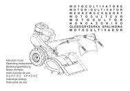
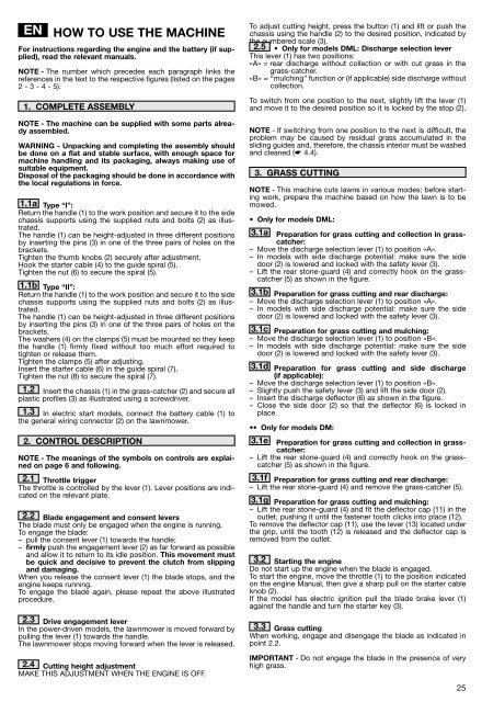
EN<br />
HOW TO USE THE MACHINE<br />
For instructions regarding the engine and the battery (if supplied),<br />
read the relevant manuals.<br />
NOTE - The number which precedes each paragraph links the<br />
references in the text to the respective figures (listed on the pages<br />
2 - 3 - 4 - 5).<br />
1. COMPLETE ASSEMBLY<br />
NOTE - The machine can be supplied with some parts already<br />
assembled.<br />
WARNING - Unpacking and completing the assembly should<br />
be done on a flat and stable surface, with enough space for<br />
machine handling and its packaging, always making use of<br />
suitable equipment.<br />
Disposal of the packaging should be done in accordance with<br />
the local regulations in force.<br />
1.1a <strong>Type</strong> “I”:<br />
Return the handle (1) to the work position and secure it to the side<br />
chassis supports using the supplied nuts and bolts (2) as illustrated.<br />
The handle (1) can be height-adjusted in three different positions<br />
by inserting the pins (3) in one of the three pairs of holes on the<br />
brackets.<br />
Tighten the thumb knobs (2) securely after adjustment.<br />
Hook the starter cable (4) to the guide spiral (5).<br />
Tighten the nut (6) to secure the spiral (5).<br />
1.1b <strong>Type</strong> “II”:<br />
Return the handle (1) to the work position and secure it to the side<br />
chassis supports using the supplied nuts and bolts (2) as illustrated.<br />
The handle (1) can be height-adjusted in three different positions<br />
by inserting the pins (3) in one of the three pairs of holes on the<br />
brackets.<br />
The washers (4) on the clamps (5) must be mounted so they keep<br />
the handle (1) firmly fixed without too much effort required to<br />
tighten or release them.<br />
Tighten the clamps (5) after adjusting.<br />
Insert the starter cable (6) in the guide spiral (7).<br />
Tighten the nut (8) to secure the spiral (7).<br />
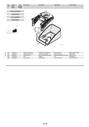
1.2 Insert the chassis (1) in the grass-catcher (2) and secure all<br />
plastic profiles (3) as illustrated using a screwdriver.<br />
1.3 In electric start models, connect the battery cable (1) to<br />
the general wiring connector (2) on the lawnmower.<br />
2. CONTROL DESCRIPTION<br />
NOTE - The meanings of the symbols on controls are explained<br />
on page 6 and following.<br />
2.1 Throttle trigger<br />
The throttle is controlled by the lever (1). Lever positions are indicated<br />
on the relevant plate.<br />
2.2 Blade engagement and consent levers<br />
The blade must only be engaged when the engine is running.<br />
To engage the blade:<br />
– pull the consent lever (1) towards the handle;<br />
– firmly push the engagement lever (2) as far forward as possible<br />
and allow it to return to its idle position. This movement must<br />
be quick and decisive to prevent the clutch from slipping<br />
and damaging.<br />
When you release the consent lever (1) the blade stops, and the<br />
engine keeps running.<br />
To engage the blade again, please repeat the above illustrated<br />
procedure.<br />
2.3 Drive engagement lever<br />
In the power-driven models, the lawnmower is moved forward by<br />
pulling the lever (1) towards the handle.<br />
The lawnmower stops moving forward when the lever is released.<br />
2.4 Cutting height adjustment<br />
MAKE THIS ADJUSTMENT WHEN THE ENGINE IS OFF.<br />
To adjust cutting height, press the button (1) and lift or push the<br />
chassis using the handle (2) to the desired position, indicated by<br />
the numbered scale (3).<br />
2.5<br />
• Only for models <strong><strong>DM</strong>L</strong>: Discharge selection lever<br />
This lever (1) has two positions:<br />
«A» = rear discharge without collection or with cut grass in the<br />
grass-catcher.<br />
«B» = “mulching” function or (if applicable) side discharge without<br />
collection.<br />
To switch from one position to the next, slightly lift the lever (1)<br />
and move it to the desired position so it is locked by the stop (2).<br />
NOTE - If switching from one position to the next is difficult, the<br />
problem may be caused by residual grass accumulated in the<br />
sliding guides and, therefore, the chassis interior must be washed<br />
and cleaned (☛ 4.4).<br />
3. GRASS CUTTING<br />
NOTE - This machine cuts lawns in various modes; before starting<br />
work, prepare the machine based on how the lawn is to be<br />
mowed.<br />
• Only for models <strong><strong>DM</strong>L</strong>:<br />
3.1a Preparation for grass cutting and collection in grasscatcher:<br />
– Move the discharge selection lever (1) to position «A».<br />
– In models with side discharge potential: make sure the side<br />
door (2) is lowered and locked with the safety lever (3).<br />
– Lift the rear stone-guard (4) and correctly hook on the grasscatcher<br />
(5) as shown in the figure.<br />
3.1b Preparation for grass cutting and rear discharge:<br />
– Move the discharge selection lever (1) to position «A».<br />
– In models with side discharge potential: make sure the side<br />
door (2) is lowered and locked with the safety lever (3).<br />
3.1c Preparation for grass cutting and mulching:<br />
– Move the discharge selection lever (1) to position «B».<br />
– In models with side discharge potential: make sure the side<br />
door (2) is lowered and locked with the safety lever (3).<br />
3.1d Preparation for grass cutting and side discharge<br />
(if applicable):<br />
– Move the discharge selection lever (1) to position «B».<br />
– Slightly push the safety lever (3) and lift the side door (2).<br />
– Insert the discharge deflector (6) as shown in the figure.<br />
– Close the side door (2) so that the deflector (6) is locked in<br />
place.<br />
•• Only for models <strong>DM</strong>:<br />
3.1e Preparation for grass cutting and collection in grasscatcher:<br />
– Lift the rear stone-guard (4) and correctly hook on the grasscatcher<br />
(5) as shown in the figure.<br />
3.1f Preparation for grass cutting and rear discharge:<br />
– Lift the rear stone-guard (4) and remove the grass-catcher (5).<br />
3.1g Preparation for grass cutting and mulching:<br />
– Lift the rear stone-guard (4) and fit the deflector cap (11) in the<br />
outlet, pushing it until the fastener tooth clicks into place (12).<br />
To remove the deflector cap (11), use the lever (13) located under<br />
the grip, until the tooth (12) is released and the deflector cap is<br />
removed from the outlet.<br />
3.2 Starting the engine<br />
Do not start up the engine when the blade is engaged.<br />
To start the engine, move the throttle (1) to the position indicated<br />
on the engine Manual, then give a sharp pull on the starter cable<br />
knob (2).<br />
If the model has electric ignition pull the blade brake lever (1)<br />
against the handle and turn the starter key (3).<br />
3.3 Grass cutting<br />
When working, engage and disengage the blade as indicated in<br />
point 2.2.<br />
IMPORTANT - Do not engage the blade in the presence of very<br />
high grass.<br />
25