

Attacchi di carica e meccanismi
Attacchi di carica e meccanismi
Attacchi di carica e meccanismi

Create successful ePaper yourself
Turn your PDF publications into a flip-book with our unique Google optimized e-Paper software.
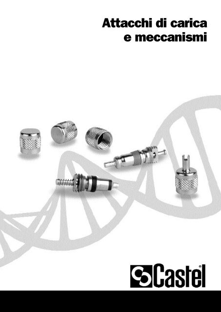
<strong>Attacchi</strong> <strong>di</strong> <strong>carica</strong><br />
e <strong>meccanismi</strong>
ATTACCHI DI CARICA E MECCANISMI<br />
IMPIEGO<br />
Tutti gli attacchi <strong>di</strong> <strong>carica</strong> e i relativi <strong>meccanismi</strong>,<br />
illustrati in questo capitolo, sono esclusi dal<br />
campo <strong>di</strong> applicazione della Direttiva 97/23/CE<br />
in quanto componenti <strong>di</strong> tubazione, come<br />
puntualizzato nelle Guideline 1/8 e 1/9.<br />
Essi sono stati progettati per essere installati<br />
su impianti <strong>di</strong> refrigerazione commerciale e<br />
con<strong>di</strong>zionamento dell’aria civile ed industriale<br />
che impieghino flui<strong>di</strong> refrigeranti appartenenti al<br />
Gruppo II (così come definito nell’Articolo 9,<br />
Punto 2.2 della Direttiva 97/23/CE, con<br />
riferimento alla Direttiva 67/548/CEE).<br />
Gli attacchi <strong>di</strong> <strong>carica</strong> permettono la realizzazione<br />
<strong>di</strong> un punto <strong>di</strong> <strong>carica</strong> o <strong>di</strong> spurgo in modo molto<br />
rapido ed economico. Una volta completata<br />
l’operazione <strong>di</strong> <strong>carica</strong> o <strong>di</strong> spurgo, il ricorso al<br />
cappuccio con guarnizione, co<strong>di</strong>ce 8392/A,<br />
previene ogni possibile per<strong>di</strong>ta <strong>di</strong> refrigerante.<br />
Per particolari esigenze del cliente, il cappuccio<br />
8392/A può essere sostituito con un<br />
bocchettone cieco, co<strong>di</strong>ce 7020/20,<br />
interponendo la guarnizione <strong>di</strong> rame,<br />
troncoconica con codolo, co<strong>di</strong>ce 8580/2.<br />
L’adozione <strong>di</strong> questa seconda soluzione richiede<br />
il serraggio del bocchettone, me<strong>di</strong>ante chiave,<br />
ad una coppia <strong>di</strong> 8,5 ÷ 11,5 Nm.<br />
Per l’impiego con fluido refrigerante R410A la<br />
<strong>di</strong>tta Castel ha realizzato tre specifici attacchi <strong>di</strong><br />
<strong>carica</strong> con connessione 5/16" SAE - Flare<br />
(co<strong>di</strong>ci 8350/X09, 8351/X05 e 8351/X07) che<br />
devono essere utilizzati in abbinamento ai<br />
seguenti componenti:<br />
- meccanismo valvola co<strong>di</strong>ce 8395/A1;<br />
- bocchettone cieco co<strong>di</strong>ce 7020/X02;<br />
Anche in tal caso è richiesto il serraggio del<br />
bocchettone, me<strong>di</strong>ante chiave, ad una coppia <strong>di</strong><br />
8,5 ÷ 11,5 Nm.<br />
FUNZIONAMENTO<br />
Gli attacchi <strong>di</strong> <strong>carica</strong>, elencati nel presente<br />
capitolo, hanno forme e <strong>di</strong>mensioni esterne<br />
<strong>di</strong>fferenti, stu<strong>di</strong>ate in funzione delle <strong>di</strong>verse<br />
esigenze dei clienti. Internamente<br />
l’alloggiamento del meccanismo, per tutti gli<br />
attacchi <strong>di</strong> <strong>carica</strong>, è realizzato secondo quanto<br />
previsto dalla norma ARI STANDARD 720:<br />
1997.<br />
154<br />
Avvitato il meccanismo all’interno dell’attacco<br />
con l’apposita chiave, co<strong>di</strong>ce 8390/A, alla<br />
coppia prevista, il passaggio del refrigerante,<br />
<strong>carica</strong> o spurgo, si ottiene semplicemente<br />
azionando lo spillo del meccanismo stesso.<br />
COSTRUZIONE<br />
Gli attacchi <strong>di</strong>ritti sono ricavati da barra<br />
esagonale <strong>di</strong> ottone EN 12164 – CW 614N.<br />
Gli attacchi a TEE e a croce sono realizzati per<br />
forgiatura a caldo <strong>di</strong> ottone EN 12420 – CW<br />
617N.<br />
I componenti dei <strong>meccanismi</strong> sono realizzati<br />
con i seguenti materiali:<br />
– ottone EN 12164 – CW 614N per il corpo;<br />
– gomma cloroprene (CR) per la guarnizione <strong>di</strong><br />
tenuta sede;<br />
– gomma cloroprene (CR) per la guarnizione <strong>di</strong><br />
tenuta verso l’esterno nei tipi 8394/A e<br />
8395/A;<br />
– PTFE per la guarnizione <strong>di</strong> tenuta verso<br />
l’esterno nel tipo 8394/B.<br />
Attacco <strong>di</strong> <strong>carica</strong> con meccanismo valvola inserito
<strong>Attacchi</strong> <strong>di</strong> <strong>carica</strong> <strong>di</strong>ritti<br />
Nr.<br />
Catalogo<br />
TABELLA 1: Caratteristiche generali<br />
8350/22 1/4" –<br />
<strong>Attacchi</strong> Dimensioni [mm]<br />
SAE Flare ODS IDS<br />
m f<br />
NPT<br />
Ø<br />
[in.]<br />
Ø<br />
[mm]<br />
Ø<br />
[in.]<br />
Ø<br />
[mm]<br />
PS<br />
[bar]<br />
L Ch D H<br />
8350/X01 1/4" – – – 6 3/8" – 20 11 – –<br />
8350/X03<br />
1/4" – – – – – 6 90 11 – –<br />
8350/X09 5/16" – – 1/4" – – – 27 14 9,4 2,1<br />
8351/2<br />
8351/X04<br />
8351/X05<br />
8351/X07<br />
1/4"<br />
5/16"<br />
8351/X02 1/4" – – – 5<br />
–<br />
–<br />
–<br />
1/4" – – – 26 11 – –<br />
–<br />
6<br />
–<br />
–<br />
–<br />
3/8"<br />
1/4"<br />
–<br />
3/8"<br />
8-10<br />
6<br />
7<br />
6<br />
30<br />
26<br />
27<br />
11<br />
14<br />
– –<br />
8 26 11 – –<br />
8352/22 1/4" – – – – – – 31 11 – –<br />
8354/21<br />
8354/22<br />
8354/23<br />
8362/22<br />
1/4" –<br />
1/8"<br />
1/4"<br />
3/8"<br />
– – – –<br />
28<br />
33<br />
38<br />
11<br />
14<br />
17<br />
– –<br />
1/4" 1/4" – – – – – 35 17 – –<br />
45<br />
155
<strong>Attacchi</strong> <strong>di</strong> <strong>carica</strong> a TEE<br />
156<br />
Nr.<br />
Catalogo<br />
8380/X01<br />
<strong>Attacchi</strong> <strong>di</strong> <strong>carica</strong> a TEE con bocchettone girevole<br />
TABELLA 2: Caratteristiche generali<br />
<strong>Attacchi</strong> Dimensioni [mm]<br />
SAE Flare IDS<br />
m f<br />
NPT<br />
Ø<br />
[in.]<br />
Ø<br />
[mm]<br />
1/4" – – – 6<br />
PS<br />
[bar]<br />
45<br />
L Ch D H<br />
43 – – 24<br />
8380/122 1/4" – 1/8" – – 45 – – 24<br />
8380/X06<br />
8380/X08<br />
1/4" 1/4" – – – 45<br />
50<br />
49<br />
– – 24<br />
Note<br />
Il meccanismo può essere<br />
montato, a scelta, su<br />
ognuno dei due attacchi<br />
da 1/4" SAE Flare.<br />
Con <strong>di</strong>spositivo d’apertura<br />
meccanismo su attacco<br />
femmina.<br />
Il meccanismo può essere<br />
montato, a scelta, su<br />
ognuno dei due attacchi<br />
da 1/4" SAE Flare.<br />
Il meccanismo può essere<br />
montato, a scelta, su<br />
ognuno dei due<br />
attacchi da 1/4" SAE<br />
Flare.
<strong>Attacchi</strong> <strong>di</strong> <strong>carica</strong> a croce<br />
Nr.<br />
Catalogo<br />
8382/1222<br />
8382/X02<br />
8382/X03<br />
TABELLA 3: Caratteristiche generali<br />
<strong>Attacchi</strong> Dimensioni [mm]<br />
SAE Flare IDS<br />
m f<br />
NPT<br />
Ø<br />
[in.]<br />
Ø<br />
[mm]<br />
1/4" – 1/8" – –<br />
<strong>Attacchi</strong> <strong>di</strong> <strong>carica</strong> a croce con bocchettone girevole<br />
8382/X04<br />
PS<br />
[bar]<br />
L Ch D H<br />
48 – – 50<br />
1/4" – 1/4" – – 45 48 – – 50<br />
1/4" – – – 6 48 – – 44<br />
1/4" 1/4" – – – 45 50 – – 46<br />
Note<br />
Il meccanismo può essere<br />
montato, a scelta, su<br />
ognuno dei tre attacchi da<br />
1/4" SAE Flare<br />
Con <strong>di</strong>spositivo d’apertura<br />
meccanismo su attacco<br />
femmina.<br />
Il meccanismo può essere<br />
montato, a scelta, su<br />
ognuno dei tre attacchi da<br />
1/4" SAE Flare.<br />
157
158<br />
Nr.<br />
Catalogo<br />
Chiave montaggio meccanismo valvola<br />
Cappucci<br />
Meccanismi valvola<br />
8390/A<br />
8392/A<br />
8392/B<br />
8394/A<br />
8394/B<br />
8395/A1<br />
Guarnizione in rame, troncoconica con codolo<br />
Collettori con attacchi <strong>di</strong> <strong>carica</strong><br />
8580/2<br />
9900/X47<br />
9900/X87<br />
TABELLA 4: Caratteristiche generali<br />
<strong>Attacchi</strong> TS [°C] Dimensioni [mm]<br />
SAE Flare IDS<br />
m f<br />
NPT<br />
Ø<br />
[in.]<br />
Ø<br />
[mm]<br />
PS<br />
[bar]<br />
min max L Ch D H<br />
– – – – – – – – 75 – – –<br />
– 1/4” – – – 35 – –<br />
– – – – –<br />
(1) -40 +100<br />
(2) -30 +90<br />
(4) -40 +100<br />
13<br />
22<br />
– 13 –<br />
– – – –<br />
1/4" – – – – 45 – – 2,8 – 5,2 –<br />
1/4" – – – – 45 –<br />
–<br />
175<br />
– –<br />
Note<br />
La chiave serve<br />
per il montaggio del<br />
meccanismo<br />
Molla esterna.<br />
Coppia serraggio<br />
0,4 / 0,8 Nm.<br />
(1) - Pressione<br />
statica: 40 [bar]<br />
(1) - Pressione <strong>di</strong><br />
lavoro: 28 [bar]<br />
Molla interna.<br />
Coppia serraggio<br />
0,30 / 0,35 Nm.<br />
(2) - Pressione<br />
statica: 40 [bar]<br />
(2) - Pressione <strong>di</strong><br />
lavoro: 28 [bar]<br />
Molla esterna.<br />
Coppia serraggio<br />
0,4 / 0,5 Nm.<br />
(4) - Pressione<br />
statica: 140 [bar]<br />
(4) - Pressione <strong>di</strong><br />
lavoro: 60 [bar]<br />
30 Quattro vie<br />
162 30 Tre vie