3.021525 - Immergas
3.021525 - Immergas
3.021525 - Immergas

Create successful ePaper yourself
Turn your PDF publications into a flip-book with our unique Google optimized e-Paper software.
Cod. 1.032824 Rev. 15.035811/000<br />
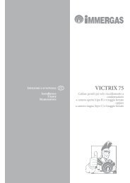
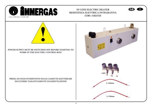
IN-LINE ELECTRIC HEATER<br />
RESISTENZA ELETTRICA INTEGRATIVA<br />
COD. <strong>3.021525</strong><br />
POWER SUPPLY MUST BE SWITCHED OFF BEFORE STARTING TO<br />
WORK IN THE ELECTRIC CONTROL BOX!<br />
230V<br />
PRIMA DI OGNI INTERVENTO SULLE CASSETTE ELETTRICHE<br />
ESCLUDERE TASSATIVAMENTE L’ALIMENTAZIONE!<br />
L=160mm<br />
L=550mm<br />
1
GENERAL RECOMMENDATIONS<br />
Please read the following safety precautions very carefully before installing the unit.<br />
SAFETY DIRECTIONS<br />
Follow the safety rules in forces when you are working on your appliance.<br />
The installation, commissioning and maintenance of these units should be performed by<br />
qualified personnel having a good knowledge of standards and local regulations, as well as<br />
experience of this type of equipment.<br />
Any wiring produced on site must comply with the corresponding national electrical<br />
regulations.<br />
Make sure that the power supply and its frequency are adapted to the required electric current<br />
of operation, taking into account specific conditions of the location and the current required<br />
for any other appliance connected with the same circuit.<br />
The unit must be EARTHED to avoid any risks caused by insulation defects.<br />
It is forbidden to start any work on the electrical components if water or high humidity is<br />
present on the installation site.<br />
WARNING<br />
When making the hydraulic connections, ensure that no impurities are introduced into the<br />
pipe work.<br />
The manufacturer declines any responsibility and the warrantly becomes void if these<br />
instructions are not respected.<br />
If you meet a problem, please call the Technical Department of your area.<br />
The information contained in these Instructions are subject to modification without advance<br />
notice.<br />
INSPECTION AND STORAGE<br />
At the time of receiving the equipment carefully cross check all the elements against the shipping<br />
documents in order to ensure that all the crates and boxes have been received. Inspect the unit<br />
for any visible or hidden damage.<br />
In the event of shipping damage, write precise details of the damage on the shipper’s delivery<br />
note and send immediately a registered letter to the shipper within 48 hours, clearly stating<br />
the damage caused. Forward a copy of this letter to the manufacturer or his representative.<br />
The unit must be stored indoors, completely protected from rain, snow etc. The unit must<br />
not be damaged by changes in the weather (high and low temperatures). Excessively high<br />
temperatures (above 60 °C) can harm certain plastic materials and cause permanent damage.<br />
Moreover, the performance of certain electrical or electronic components can be impaired.<br />
WARRANTY<br />
Any modification to the unit without the manufacturer’s prior approval, shall automatically<br />
render the warranty null and void.<br />
The following conditions must be respected in order to maintain the validity of the warranty:<br />
• Commissioning shall be performed by specialised technicians.<br />
• Maintenance shall be performed by technicians trained for this purpose.<br />
• Only Original Equipment spare parts shall be used.<br />
• All the operations listed in the present manual shall be performed within the<br />
prescribed SCHEDULE.<br />
THE WARRANTY SHALL BE NULL AND VOID IN THE EVENT OF<br />
NON-COMPLIANCE WITH ANY OF THE ABOVE CONDITIONS.<br />
2
PRODUCT PRESENTATION<br />
This additional electric heater has been designed to operate in association with a PAC in a<br />
clear water or glycol mixture (40% maximum) water heating system. It offers three heating<br />
capacities of 2kW, 4kW and 6kW that are controlled independently and it offers the possibility<br />
of single phase and three phase connections.<br />
It can be used to provide additional heating capacity when the demand for heating exceeds<br />
the capacity supplied by the Heat Pump.<br />
HEATER 6 KW 6KW<br />
POWER SUPPLY<br />
230V - 50Hz SINGLE PHASE +<br />
GROUND<br />
400V - 50Hz THREE PHASE + N +<br />
GROUND<br />
TOTAL MAXIMUM CURRENT 31.5A 10.5A<br />
POWER SUPPLY PROTECTION<br />
(not supplied)<br />
POWER CABLE 3G6 5G1.5<br />
LINK CABLE<br />
PAC KIT<br />
32A<br />
2G1<br />
12A<br />
2G1<br />
INSTALLATION<br />
The heater has been designed for indoor installation in the home in an explosion risk-free<br />
area and, if possible, protected from sub-zero temperatures. This device is not sealed against<br />
water splashes and must not be installed in damp surroundings, such as wash houses or<br />
laundry rooms.<br />
HYDRAULIC CONNECTIONS<br />
The heater must be installed in a horizontal position, always downstream of the PAC (refer to<br />
assembly layout drawing). It will not operate without a water supply, (risk of boiling). If the<br />
heater is installed directly in the water circuit (water flow guaranteed by the PAC circulation<br />
pump), the PAC system controls the risk of low water flow. If the heater is installed in a<br />
separate heating circuit, the installer must ensure that an adequate water flow is guaranteed.<br />
If water cut-off devices, such as valves, are installed between the PAC and the heater, meaning<br />
that it can be hydraulically isolated, a safety valve must be also installed. (Refer to assembly<br />
layout drawing).<br />
ELECTRICAL CONNECTIONS<br />
The power supply must pass through a CIRCUIT BREAKER or FUSE HOLDER provided by<br />
the installer. Fuse sizes are indicated in the following table.<br />
Make sure that the ground cable is connected properly before closing the<br />
heater cover.<br />
COMMISSIONING<br />
Fill the circuit water and check that it is fully watertight.<br />
Bleed the entire heating circuit and check that an adequate water flow is present before<br />
switching on the heating resistances.<br />
This heater is equipped with a dual safety thermostat: automatic reset at 70° C and manual<br />
reset at 83° C.<br />
OPERATING MODES (parameters to be set on the Heat Pump)<br />
BOOST MODE<br />
The aim is to maintain occupier comfort when the Heat Pump lacks sufficient power, while<br />
favouring operation of the thermodynamic section for optimal performance.<br />
The resistances are only activated if the Heat Pump detects a lack of capacity from the<br />
thermodynamic section (via measurement of water temperature).<br />
To configure the intervention of the supplementary heater refer to the heat pump<br />
documentation.<br />
The electrical installation and wiring of the heater must comply with current regulations in<br />
the country of installation.<br />
The appliance must be EARTHED to avoid any possible danger caused by<br />
faulty insulation.<br />
3
RACCOMANDAZIONI GENERALI<br />
Leggere attentamente le seguenti avvertenze di sicurezza prima di installare l’apparecchio.<br />
CONSIGLI DI SICUREZZA<br />
Quando intervenite sul vostro kit, seguite le regole di sicurezza in vigore.<br />
L’installazione, l’utilizzo e la manutenzione devono essere eseguiti da personale qualificato<br />
che conosca bene la legislazione e la regolamentazioni locali e avente una certa esperienza<br />
per quanto riguarda questo tipo di attrezzature.<br />
Tutti i collegamenti devono essere eseguiti conformemente alla relativa regolamentazione<br />
nazionale.<br />
Assicuratevi che la potenza elettrica disponibile e la frequenza della rete siano adatte al corretto<br />
funzionamento del dispositivo, tenuto conto delle condizioni specifiche dell’ubicazione, e che la<br />
potenza sia sufficiente per alimentare qualsiasi altro apparecchio collegato allo stesso circuito.<br />
L’apparecchio deve essere COLLEGATO ALLA TERRA per evitare gli eventuali pericoli<br />
risultanti dai difetti di isolamento.<br />
Tutti gli interventi sugli elementi elettrici dell’apparecchio sono vietato in presenza di acqua<br />
e di umidità.<br />
AVVERTENZA<br />
Al momento del collegamento idraulico, far attenzione ad evitare ogni introduzione di corpi<br />
estranei nella tubazione.<br />
Il fabbricante declina qualsiasi responsabilità e la garanzia non sarà più valida qualora le<br />
presenti istruzioni non venissero rispettate.<br />
In caso di difficoltà, non esitate a contattare al Centro Assistenza Tecnica Autorizzato della<br />
vostra zona di appartenenza.<br />
Le informazioni contenute nelle presenti istruzioni per l’uso sono soggette a modifiche senza<br />
preavviso.<br />
CONTROLLO E STOCCAGGIO<br />
Al ricevimento dell’attrezzatura, verificare accuratamente tutti gli elementi facendo riferimento<br />
alla bolla di trasporto onde assicurarsi che tutte le casse e tutti i cartoni siano stati ricevuti.<br />
Controllare l’apparecchio per ricercare i danni visibili o nascosti.<br />
In caso di danneggiamento, avanzare riserve precise sul documento di trasporto e<br />
inviare immediatamente una lettera raccomandata al corriere indicando chiaramente<br />
i danneggiamenti subiti dall’apparecchio. Trasmettere una copia di questa lettera al<br />
costruttore o al rappresentante dello stesso.<br />
L’apparecchio deve essere immagazzinato, interamente al riparo dalla pioggia, dalla neve, ecc. Le<br />
variazioni meteorologiche (temperature elevate e basse) non devono danneggiare l’apparecchio.<br />
Temperature troppo elevate (a partire dai 60°C) possono deteriorare alcune materie plastiche<br />
e provocare danni permanenti. Inoltre, alcuni componenti elettrici o elettronici possono non<br />
funzionare correttamente.<br />
GARANZIA<br />
Qualsiasi modifica della unità, senza previo assenso scritto del costruttore, comporterà<br />
l’annullamento della garanzia.<br />
Per mantenere la validità della garanzia, devono essere tassativamente soddisfatte le seguenti<br />
condizioni:<br />
• L’installazione dovrà essere eseguita da un Tecnico abilitato.<br />
• La manutenzione dovrà essere eseguita da un Centro Assistenza Tecnica<br />
Autorizzato.<br />
• Dovranno essere usati soltanto pezzi di ricambio originali.<br />
• Tutte le operazioni riportate nel presente manuale dovranno essere eseguite<br />
entro i termini concordati.<br />
SE ANCHE UNA SOLA DELLE CONDIZIONI SOPRA MENZIONATE<br />
NON VIENE SODDISFATTA, LA GARANZIA SI RITIENE<br />
AUTOMATICAMENTE ANNULLATA.<br />
4
PRESENTAZIONE DEL PRODOTTO<br />
Il riscaldatore elettrico addizionale è stato appositamente progettato per funzionare in<br />
associazione con una pompa di calore su un impianto di riscaldamento in acqua pura o<br />
glicolata (40% max). Comprende 3 stadi di potenza da 2, 4 kW e 6 kW pilotati separatamente<br />
con possibilità di cablaggio monofase o trifase.<br />
Può essere utilizzato per il riscaldamento aggiuntivo in modo da assicurare un complemento di<br />
potenza quando la domanda di riscaldamento è superiore alla capacità della pompa di calore.<br />
RISCALDATORE 6 KW 6KW<br />
ALIMENTAZIONE ELETTRICA<br />
230V - 50Hz MONOFASE + TERRA<br />
400V - 50Hz TRIFASE + N +<br />
TERRA<br />
INTENSITÀ TOTALE MAX. 31.5A 10.5A<br />
PROTEZIONE GENERALE<br />
(non fornita)<br />
CAVO D’ALIMENTAZIONE 3G6 5G1.5<br />
CAVO DI COLLEGAMENTO<br />
Pompa di calore KIT<br />
32A<br />
2G1<br />
12A<br />
2G1<br />
Prima di richiudere il coperchio del riscaldatore, assicurarsi che il cavo di<br />
terra sia correttamente collegato.<br />
INSTALLAZIONE<br />
Il riscaldatore è stato appositamente progettato per essere installato all’interno di edifici<br />
domestici (atmosfera non esplosiva) in zone non soggette a gelo. Tale apparecchio non è<br />
stagno alle proiezioni d’acqua e non può essere installato in locali umidi del tipo lavanderia.<br />
COLLEGAMENTI IDRAULICI<br />
Il riscaldatore deve essere installato orizzontalmente sempre a valle della pompa di calore (vedi<br />
pianta di montaggio) Non può funzionare senza portata d’acqua (rischio di ebollizione). In<br />
caso di montaggio del riscaldatore in un circuito diretto (portata d’acqua assicurata da parte<br />
del circolatore della pompa di calore), la mancanza di portata è controllata dalla pompa di<br />
calore. In caso di montaggio su circuito di riscaldamento disaccoppiato, l’installatore verificherà<br />
il rispetto della portata d’acqua.<br />
In caso di inserimento di organi di interruzione idraulica (valvole, …) tra la pompa di calore<br />
ed il riscaldatore che serve ad isolare idraulicamente questo ultima, si dovrà obbligatoriamente<br />
installare una valvola di sicurezza. Vedi schema di montaggio.<br />
COLLEGAMENTI ELETTRICI<br />
L'alimentazione proviene da un INTERRUTTORE AUTOMATICO o da un PORTAFUSIBILI<br />
fornito dall’installatore. I calibri sono riportati nella tabella di cui sotto.<br />
L’impianto elettrico ed il cablaggio dell’unità devono essere conformi alle norme in vigore<br />
nel paese d’installazione.<br />
AVVIO<br />
Riempire il circuito d’acqua e verificare l’assenza di perdite.<br />
Spurgare tutto il circuito di riscaldamento e verificare che sia presente una portata d’acqua<br />
corretta prima di qualsiasi messa sotto tensione delle resistenze.<br />
Il riscaldatore è dotato di un doppio termostato di sicurezza: riarmo automatico a 70°C e<br />
riarmo manuale a 83°C.<br />
MODI DI FUNZIONAMENTO (da parametrare sulla pompa di<br />
calore)<br />
MODO RISCALDAMENTO AGGIUNTIVO<br />
Lo scopo è quello di mantenere il comfort delle persone presenti nel locale quando la pompa<br />
di calore non è abbastanza potente privilegiando il funzionamento della parte termodinamica<br />
al fine di ottenere prestazioni ottimali.<br />
Le resistenze sono attivate soltanto se la pompa di calore rileva una mancanza di potenza della<br />
parte termodinamica (controllo della temperatura dell’acqua).<br />
Per la configurazione dell'intervento della resistenza integrativa far riferimento alla<br />
documentazione della pompa di calore.<br />
L’apparecchio deve essere COLLEGATO ALLA TERRA per evitare gli<br />
eventuali pericoli causati da difetti di isolamento.<br />
5
62<br />
357<br />
C<br />
300<br />
99.50<br />
Ø8<br />
25.50<br />
69<br />
178<br />
145 50<br />
B<br />
26<br />
E<br />
601<br />
223<br />
107<br />
34<br />
D<br />
A<br />
59<br />
40<br />
125<br />
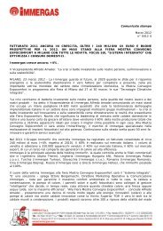
7 kg<br />
19<br />
A<br />
B<br />
C<br />
D<br />
E<br />
Water inlet/outlet<br />
1"1/2 male gas (40x49) flat<br />
joint connection<br />
Ingresso/Uscita acqua<br />
1"1/2 gas maschio (40x49) raccordo<br />
a guarnizione piatta<br />
Mains power supply Alimentazione elettrica<br />
Bleed Rubinetto di scarico<br />
Backup heater operating<br />
lswitch<br />
Drain<br />
Ø1/2" male gas (15x21)<br />
Interruttore riscaldamento de<br />
emergenza<br />
valvola di scarico<br />
Ø1/2" gas maschio (15x21)<br />
6
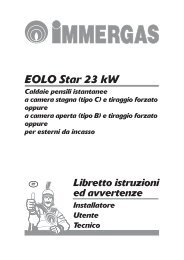
Example of fitting in a constant flow circuit<br />
Esempio di montaggio su circuito a portata costante<br />
1<br />
3<br />
8<br />
1 1<br />
7<br />
1<br />
6<br />
1<br />
5<br />
10<br />
9<br />
11<br />
1<br />
1<br />
1<br />
1<br />
3<br />
1 1<br />
4<br />
7
1 Stop cocks<br />
3 Filter or sludge trap<br />
4 Expansion tank<br />
5 3-way valve – Domestic Hot<br />
Water<br />
6 Domestic Hot Water tank<br />
7 Safety devices<br />
8 Recycling circulation pump<br />
(optional)<br />
9 In-line heater<br />
10 Bleed<br />
11 Safety valve<br />
1 Valvole di intercettazione<br />
3 Filtro o defangatore<br />
4 Vaso di espansione<br />
5 Valvola a 3 vie dell’acqua calda<br />
sanitaria<br />
6 Accumulatore di acqua calda<br />
sanitaria<br />
7 Gruppo di sicurezza sanitaria<br />
8 Circolatore di ricircolo (optional)<br />
9 Riscaldatore in linea<br />
10 Rubinetto di scarico<br />
11 Valvola di sicurezza<br />
For more information on hydraulic<br />
layouts, refer to the Heat Pump<br />
documentation.<br />
Per maggiori informazioni sugli<br />
schemi di montaggio, far riferimento<br />
alla documentazione della pompa di<br />
calore.<br />
8
230V +/-10% 50Hz<br />
2 kW - 400 Vac<br />
4 kW - 400 Vac<br />
6 kW - 400 Vac<br />
3N~400V +/-10% 50Hz<br />
2 kW - 230 Vac<br />
utilizzare il kit presente nella confezione<br />
use the kit in the package<br />
4 kW - 230 Vac<br />
utilizzare il kit presente nella confezione<br />
use the kit in the package<br />
6 kW - 230 Vac<br />
utilizzare il kit presente nella confezione<br />
use the kit in the package<br />
230V +/-10% 50Hz<br />
10
RESET SAFETY DEVICE<br />
The electric heating system is equipped with 1 SAFETY DEVICE. It cuts off electrical supply<br />
to the heating resistances as soon as an operating anomaly is detected.<br />
RIARMO SICUREZZE<br />
Il riscaldamento elettrico è dotato di 1 SICUREZZA con due livelli d'intervento, una a riarmo<br />
automatico ed una a riarmo manuale, che tolgono alimentazione alle resistenze riscaldanti<br />
non appena viene rilevata un’anomalia nel funzionamento dell’apparecchio.<br />
11
Legenda:<br />
BN - Marrone<br />
BK - Nero<br />
BU - Blu<br />
GY - Grigio<br />
GNYE - Green / Yellow<br />
OG - Arancione<br />
RD - Rosso<br />
VT - Viola<br />
WH - Bianco<br />
KC1 - Relè resistenze fase 1<br />
KC2 - Relè resistenze fase 2<br />
FCA - Protezione termica a riarmo automatico<br />
FCM - Protezione termica a riarmo manuale<br />
ICS - Interruttore abilitazione<br />
HCS - Segnalazione abilitazione<br />
R - Resistenze elettriche<br />
Θ><br />
Θ><br />
Legend:<br />
BN - Brown<br />
BK - Black<br />
BU - Blue<br />
GY - Grey<br />
GNYE - Green / Yellow<br />
OG - Orange<br />
RD - Red<br />
VT - Violet<br />
WH - White<br />
KC1 - Heater stage 1 relay<br />
KC2 - Heater stage 2 relay<br />
FCA - High temperature automatic reset cut-cut<br />
FCM - High temperature manual reset cut-cut<br />
ICS - enable switch<br />
HCS - operating light<br />
R - electric heater<br />
12