download (3,6 Mb) - Immergas
download (3,6 Mb) - Immergas
download (3,6 Mb) - Immergas

Create successful ePaper yourself
Turn your PDF publications into a flip-book with our unique Google optimized e-Paper software.
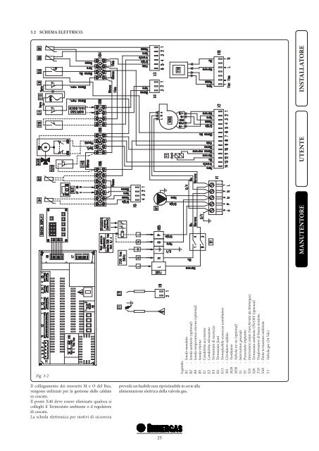
3.2 SCHEMA ELETTRICO.<br />
MANUTENTORE<br />
UTENTE<br />
INSTALLATORE<br />
Fig. 3-2<br />
Il collegamento dei morsetti M e O del Bus,<br />
vengono utilizzati per la gestione delle caldaie<br />
in cascata.<br />
Il ponte X40 deve essere eliminato qualora si<br />
colleghi il Termostato ambiente o il regolatore<br />
di cascata.<br />
La scheda elettronica per motivi di sicurezza<br />
prevede un fusibile non ripristinabile in serie alla<br />
alimentazione elettrica della valvola gas.<br />
Legenda:<br />
B1 - Sonda mandata<br />
B2 - Sonda sanitario (optional)<br />
B4 - Sonda temperatura esterna (optional)<br />
B5 - Sonda ritorno<br />
E1 - Candeletta accensione<br />
E2 - Candeletta rilevazione<br />
E4 - Termostato di sicurezza<br />
E6 - Termostato fumi<br />
E13 - Termofusibile sicurezza scambiatore<br />
M1 - Circolatore caldaia<br />
M20 - Ventilatore<br />
M30 - Valvola tre vie (optional)<br />
S1 - Interruttore generale<br />
S5 - Pressostato impianto<br />
S16 - Interruttore estate (non fornito da <strong>Immergas</strong>)<br />
S20 - Termostato ambiente ON/OFF (optional)<br />
T10 - Trasformatore di bassa tensione<br />
X40 - Ponte termostato ambiente<br />
Y1 - Valvola gas (24 Vdc)<br />
25