

Kit di zona a pressione controllata - Caleffi
Kit di zona a pressione controllata - Caleffi
Kit di zona a pressione controllata - Caleffi

You also want an ePaper? Increase the reach of your titles
YUMPU automatically turns print PDFs into web optimized ePapers that Google loves.
<strong>Kit</strong> <strong>di</strong> <strong>zona</strong><br />
a <strong>pressione</strong> <strong>controllata</strong><br />
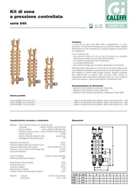
serie 640<br />
Gamma prodotti<br />
cert. n° 0003<br />
ISO 9001<br />
CALEFFI<br />
01087/02<br />
Funzione<br />
Il nuovo kit <strong>di</strong> <strong>zona</strong> serie 640 mette a <strong>di</strong>sposizione, in unica<br />
soluzione, i componenti necessari per la costituzione della cassetta<br />
dell’impianto a zone, rendendo più rapide ed agevoli le operazioni<br />
<strong>di</strong> installazione.<br />
Il kit è composto da :<br />
- Una valvola <strong>di</strong> <strong>zona</strong> a 3 vie con tee <strong>di</strong> by-pass con comando<br />
elettrotermico dotato <strong>di</strong> microinterruttore ausiliario.<br />
- Un collettore complanare fuso monoblocco.<br />
- Un by-pass <strong>di</strong>fferenziale.<br />
- Due valvole <strong>di</strong> sfogo aria con tappo igroscopico <strong>di</strong> sicurezza.<br />
Particolarmente importante è la funzione del by pass <strong>di</strong>fferenziale<br />
che mantiene <strong>controllata</strong> la <strong>pressione</strong> dei circuiti <strong>di</strong> andata e ritorno<br />
del collettore al variare della portata richiesta. Questa variazione<br />
può determinarsi a seguito della chiusura delle valvole <strong>di</strong><br />
regolazione della temperatura ambiente poste sui corpi scaldanti<br />
come, ad esempio, valvole termostatiche od elettrotermiche.<br />
Documentazione <strong>di</strong> riferimento<br />
- Depliant 01014 Collettori complanari. Serie 356.<br />
- Depliant 01072 Valvole <strong>di</strong> <strong>zona</strong>. Serie 676.<br />
- Depliant 01054 Valvole automatiche <strong>di</strong> sfogo aria. Serie 5020.<br />
Co<strong>di</strong>ce 640542 <strong>Kit</strong> <strong>di</strong> <strong>zona</strong> 4+4 attacco <strong>di</strong> testa 3/4”M a bocchettone, attacco derivazioni 23 p. 1,5M<br />
Co<strong>di</strong>ce 640562 <strong>Kit</strong> <strong>di</strong> <strong>zona</strong> 6+6 attacco <strong>di</strong> testa 3/4”M a bocchettone, attacco derivazioni 23 p. 1,5M<br />
Co<strong>di</strong>ce 640582 <strong>Kit</strong> <strong>di</strong> <strong>zona</strong> 8+8 attacco <strong>di</strong> testa 3/4”M a bocchettone, attacco derivazioni 23 p. 1,5M<br />
Caratteristiche tecniche e costruttive<br />
Materiali: - Corpi valvola <strong>di</strong> sfogo aria, valvola <strong>di</strong> <strong>zona</strong><br />
e by-pass ottone, UNI EN 12165 CW 617N<br />
- Corpo collettore ottone, UNI EN 1982 CB 753S<br />
- Otturatore valvola <strong>di</strong> <strong>zona</strong>: ottone, UNI EN 12165 CW 617N<br />
- Tenute idrauliche: EPDM<br />
- Asta <strong>di</strong> comando valvola <strong>di</strong> <strong>zona</strong>: acciaio inox<br />
- Galleggiante valvola sfogo aria: PP<br />
Pressione max esercizio: 10 bar<br />
Pressione <strong>di</strong>fferenziale max valvola <strong>di</strong> <strong>zona</strong>: 1,2 bar<br />
Pressione <strong>di</strong>fferenziale del by-pass: 20 kPa (2000 mm c.a.)<br />
Pressione max <strong>di</strong> scarico valvola sfogo aria: 2,5 bar<br />
Campo temperatura: 0÷95°C<br />
Fluido d’impiego: acqua, soluzioni glicolate<br />
Massima percentuale <strong>di</strong> glicole: 30%<br />
Alimentazione servocomando: 220V<br />
Corrente <strong>di</strong> spunto: 0,6 A<br />
Corrente a regime: 13 mA<br />
Assorbimento a regime: 3 W<br />
Portata contatti microinterruttore ausiliario: 0,8 A<br />
Attacchi: - <strong>di</strong> testa; 3/4” M a bocchettone<br />
- derivazioni; 23 p. 1,5 M<br />
Dimensioni<br />
Co<strong>di</strong>ce<br />
640542<br />
640562<br />
640582<br />
n. deriv.<br />
4+4<br />
6+6<br />
8+8<br />
A<br />
60<br />
60<br />
60<br />
Mod. Dep.<br />
CALEFFI<br />
A<br />
B<br />
23 p. 1,5<br />
23 p. 1,5<br />
23 p. 1,5<br />
356<br />
F<br />
B<br />
C<br />
126<br />
126<br />
126<br />
D<br />
C<br />
D<br />
40<br />
40<br />
40<br />
E<br />
E<br />
405<br />
485<br />
565<br />
F<br />
142<br />
142<br />
142
Caratteristiche fluido<strong>di</strong>namiche<br />
Valvola <strong>di</strong> <strong>zona</strong><br />
∆P (mm c.a.)<br />
10000 9000<br />
8000<br />
7000<br />
6000<br />
5000<br />
2000<br />
1000<br />
500<br />
200<br />
100<br />
3000<br />
1800<br />
1600<br />
1400<br />
1200<br />
900<br />
800<br />
700<br />
600<br />
50<br />
20<br />
4000<br />
400<br />
300<br />
180<br />
160<br />
140<br />
120<br />
90<br />
80<br />
70<br />
60<br />
40<br />
30<br />
200<br />
Collettore<br />
250<br />
300<br />
350<br />
400<br />
450<br />
By-pass Aperto<br />
500<br />
600<br />
G (l/h)<br />
Coefficiente per<strong>di</strong>ta localizzata ξ <strong>di</strong> imbocco (A+R): 3,0<br />
Coefficiente per<strong>di</strong>ta localizzata ξ delle derivazioni (A+R): 6,5<br />
700<br />
800<br />
900<br />
1000<br />
1200<br />
1400<br />
1600<br />
∆P (kPa)<br />
Serie DN<br />
Kv (m ∆pmax *<br />
(bar)<br />
3 /h)<br />
<strong>di</strong>ritta by-pass<br />
678 3/4” 3,7 1,0 1,2<br />
* Pressione <strong>di</strong>fferenziale massima assicurata dal servocomando per il regolare funzionamento<br />
By-pass <strong>di</strong>fferenziale<br />
∆P (mm c.a.)<br />
10000<br />
5000<br />
2000<br />
1000<br />
9000<br />
8000<br />
7000<br />
6000<br />
4500<br />
4000<br />
3500<br />
3000<br />
2500<br />
1800<br />
1600<br />
1400<br />
1200<br />
50<br />
60<br />
70<br />
80<br />
90<br />
100<br />
120<br />
140<br />
160<br />
180<br />
200<br />
250<br />
300<br />
350<br />
400<br />
450<br />
500<br />
600<br />
1800<br />
700<br />
800<br />
900<br />
2000<br />
90<br />
80<br />
70<br />
60<br />
40<br />
30<br />
18<br />
16<br />
14<br />
12<br />
100<br />
1,8<br />
1,6<br />
1,4<br />
1,2<br />
0,9<br />
0,8<br />
0,7<br />
0,6<br />
0,4<br />
0,3<br />
50<br />
20<br />
10<br />
5<br />
2<br />
1<br />
G (l/h)<br />
0,5<br />
0,2<br />
∆P (kPa)<br />
90<br />
80<br />
70<br />
60<br />
1000<br />
45<br />
40<br />
35<br />
30<br />
25<br />
18<br />
16<br />
14<br />
12<br />
100<br />
50<br />
20<br />
10<br />
Particolarità costruttive<br />
Valvola <strong>di</strong> sfogo aria<br />
Le due valvole <strong>di</strong> sfogo aria sono dotate <strong>di</strong> tappo igroscopico<br />
automatico <strong>di</strong> sicurezza. Questo <strong>di</strong>spositivo consente lo sfogo<br />
dell’aria senza intervento manuale. In caso <strong>di</strong> contatto con l’acqua,<br />
esso chiude automaticamente il passaggio <strong>di</strong> scarico.<br />
Collettore complanare<br />
Questi collettori sono realizzati me<strong>di</strong>ante una fusione monoblocco,<br />
senza collegamenti riportati tra i condotti interni. In questo modo viene<br />
eliminata una possibile causa <strong>di</strong> per<strong>di</strong>te dovute all’accoppiamento <strong>di</strong><br />
metalli con <strong>di</strong>fferenti coefficienti <strong>di</strong> <strong>di</strong>latazione termica.<br />
Gli attacchi delle derivazioni laterali sono ricavati tangenzialmente<br />
rispetto ai condotti principali, per rendere più agevole il montaggio<br />
dei raccor<strong>di</strong>.<br />
Valvola <strong>di</strong> <strong>zona</strong><br />
L’asta <strong>di</strong> comando in acciaio inox ha una doppia tenuta idraulica<br />
realizzata me<strong>di</strong>ante due O-Ring in EPDM; in questo modo la parte<br />
superiore del vitone può essere sostituita anche ad impianto<br />
funzionante.<br />
Installazione<br />
Il kit <strong>di</strong> <strong>zona</strong>, fornito con mandata a destra è confezionato con<br />
valvole <strong>di</strong> sfogo aria, by pass <strong>di</strong>fferenziale e collettore, premontati.<br />
E’ importante che, per il<br />
corretto funzionamento<br />
del kit, il senso <strong>di</strong> flusso<br />
del fluido rispetti la<br />
<strong>di</strong>rezione della freccia<br />
presente sul by-pass.<br />
Se particolari esigenze<br />
<strong>di</strong> installazione non<br />
consentono <strong>di</strong><br />
assecondare questa<br />
prescrizione, smontare<br />
il by pass e ruotarlo <strong>di</strong><br />
180° in modo che<br />
rispetti il senso <strong>di</strong><br />
flusso.<br />
La valvola <strong>di</strong> <strong>zona</strong> deve essere sempre installata sulla mandata.<br />
Collegamenti elettrici comando elettrotermico<br />
Termostato<br />
TESTO DI CAPITOLATO<br />
1 2 3 4<br />
Ω<br />
3 Watt max 0,8 A<br />
Mod. Dep.<br />
CALEFFI<br />
356<br />
1 Marrone<br />
2 Blu<br />
Serie 640<br />
<strong>Kit</strong> <strong>di</strong> <strong>zona</strong> a <strong>pressione</strong> <strong>controllata</strong>, derivazioni 4+4 (6+6 o 8+8) Attacchi <strong>di</strong> testa 3/4”M a bocchettone. Attacchi derivazioni<br />
23p.1,5M. Corpi in ottone. Tenute idrauliche EPDM. Pmax d’esercizio 10 bar. Campo <strong>di</strong> temperatura d’esercizio 0÷95°C.<br />
Costituito da:<br />
- Collettore complanare fuso monoblocco.<br />
- Valvola <strong>di</strong> <strong>zona</strong> 3 vie con tee <strong>di</strong> by-pass. Pressione <strong>di</strong>fferenziale max 1,2 bar.<br />
- Servomotore 220V corredato <strong>di</strong> microinterruttore ausiliario. Corrente <strong>di</strong> spunto 0,6 A. Corrente a regime 13 mA.<br />
- By pass <strong>di</strong>fferenziale. Attacchi 3/4”M x 3/8”F. Pressione <strong>di</strong>fferenziale 20 kPa.<br />
- Valvole sfogo aria. Pmax <strong>di</strong> scarico 2,5 bar. Corredate <strong>di</strong> tappo igroscopico <strong>di</strong> sicurezza.<br />
Ci riserviamo il <strong>di</strong>ritto <strong>di</strong> apportare miglioramenti e mo<strong>di</strong>fiche ai prodotti descritti ed ai relativi dati tecnici in qualsiasi momento e senza preavviso.<br />
CALEFFI<br />
CALEFFI S.P.A. · S.R.229, N.25 · 28010 FONTANETO D’AGOGNA (NO) · TEL. 0322 8491 · FAX 0322 863305<br />
· www.caleffi.it · info@caleffi.it ·<br />
L<br />
N<br />
Mod. Dep.<br />
CALEFFI<br />
220 V<br />
50 Hz<br />
3 Nero<br />
4 Nero<br />
356


