

Depliant 01053 Valvole di sicurezza per impianti termici - Caleffi
Depliant 01053 Valvole di sicurezza per impianti termici - Caleffi
Depliant 01053 Valvole di sicurezza per impianti termici - Caleffi

You also want an ePaper? Increase the reach of your titles
YUMPU automatically turns print PDFs into web optimized ePapers that Google loves.
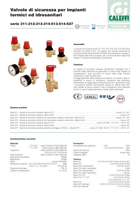
<strong>Valvole</strong> <strong>di</strong> <strong>sicurezza</strong> <strong>per</strong> <strong>impianti</strong><br />
<strong>termici</strong> ed idrosanitari<br />
serie 311-312-313-314-513-514-527<br />
Gamma prodotti<br />
Caratteristiche tecniche<br />
Materiali:<br />
Corpo: - 1/2”-3/4”: ottone UNI EN 12165 CW617N<br />
- 1”-1 1/4”: ottone UNI EN 1982 CB753S<br />
Co<strong>per</strong>chio: ottone UNI EN 12165 CW617N<br />
513-514 (1/2”); PA 6 G 30<br />
Asta comando: ottone UNI EN 12164 CW614N<br />
Guarnizione otturatore: EPDM<br />
Membrana: EPDM<br />
Molla: acciaio UNI 3823<br />
Manopola comando: - 311-312-313-314-513 (1/2”)-514; ABS<br />
- 513 (1” e 1 1/4”)-527; PA 6 G 20<br />
Pressione nominale: PN 10<br />
Campo <strong>di</strong> tem<strong>per</strong>atura: 5÷110°C<br />
REGI STERED BSI EN ISO 9001:2000<br />
Generalità<br />
<strong>01053</strong>/08<br />
sostituisce dp <strong>01053</strong>/02<br />
Le valvole <strong>di</strong> <strong>sicurezza</strong> serie 311, 312, 313, 314, 513, 514, 527 sono<br />
costruite da <strong>Caleffi</strong> S.p.A. nel rispetto dei requisiti essenziali <strong>di</strong><br />
<strong>sicurezza</strong> dettati dalla <strong>di</strong>rettiva 97/23/CE del parlamento europeo e<br />
del consiglio dell’unione europea, <strong>per</strong> il riavvicinamento degli stati<br />
membri in materia <strong>di</strong> attrezzature a pressione.<br />
Funzione<br />
Cert. n° FM 21654<br />
UNI EN ISO 9001:2000<br />
Cert. n° 0003<br />
CALEFFI<br />
Le valvole <strong>di</strong> <strong>sicurezza</strong> vengono tipicamente impiegate <strong>per</strong> il<br />
controllo della pressione sui generatori <strong>di</strong> calore negli <strong>impianti</strong> <strong>di</strong><br />
riscaldamento, sugli accumuli <strong>di</strong> acqua calda negli <strong>impianti</strong><br />
idrosanitari e negli <strong>impianti</strong> idrici.<br />
Al raggiungimento della pressione <strong>di</strong> taratura, la valvola si apre e,<br />
me<strong>di</strong>ante lo scarico in atmosfera, impe<strong>di</strong>sce alla pressione<br />
dell’impianto <strong>di</strong> raggiungere limiti <strong>per</strong>icolosi <strong>per</strong> il generatore e <strong>per</strong><br />
i componenti presenti nell’impianto stesso. Le valvole serie 527<br />
sono dotate <strong>di</strong> azione positiva, cioè le prestazioni sono garantite<br />
anche in caso <strong>di</strong> deterioramento o rottura della membrana.<br />
Serie 311 Valvola <strong>di</strong> <strong>sicurezza</strong> or<strong>di</strong>naria. Attacchi F-F. misure 1/2”, 3/4”<br />
Serie 312 Valvola <strong>di</strong> <strong>sicurezza</strong> or<strong>di</strong>naria. Attacchi M-F. misura 1/2”<br />
Serie 313 Valvola <strong>di</strong> <strong>sicurezza</strong> or<strong>di</strong>naria con manometro o attacco manometro. Attacchi F-F. misure 1/2”, 3/4”<br />
Serie 314 Valvola <strong>di</strong> <strong>sicurezza</strong> or<strong>di</strong>naria con manometro o attacco manometro. Attacchi M-F. misura 1/2”<br />
Serie 513 Valvola <strong>di</strong> <strong>sicurezza</strong> or<strong>di</strong>naria. Attacchi F-F. misure 1/2”x3/4”, 1”x1 1/4”, 1 1/4”x1 1/2”<br />
Serie 514 Valvola <strong>di</strong> <strong>sicurezza</strong> or<strong>di</strong>naria. Attacchi M-F. misura 1/2”<br />
Serie 527 Valvola <strong>di</strong> <strong>sicurezza</strong> ad azione positiva omologata I.S.P.E.S.L.. Attacchi F-F. misure 1/2”x3/4”, 3/4”x1”, 1”x1 1/4”, 1 1/4”x1 1/2”<br />
1115<br />
I.S.P.E.S.L.<br />
Prestazioni:<br />
Sovrappressione a<strong>per</strong>tura: - 527: 10%<br />
- 311-312-313-513-514; 20%<br />
Scarto <strong>di</strong> chiusura: 20%<br />
Fluido d’impiego: acqua, aria<br />
Categoria PED: IV<br />
Tarature:<br />
Serie 311 2-2,5-3-3,5-4-5-6-7-8 bar (2 solo 3/4”)<br />
Serie 312 2,5-3-3,5-4-5-6-7-8 bar<br />
Serie 313 c/manometro 2,5-3-6-7-8 bar<br />
Serie 313 c/att. manometro 3 bar<br />
Serie 314 c/manometro 2,5-3-6-7-8 bar<br />
Serie 314 c/att. manometro 3-6 bar<br />
Serie 513 1/2” 1,5-2-2,5-3-3,5-6-7-8 bar<br />
Serie 513 1”-1 1/4” 2,5-3-3,5-6-7-8 bar<br />
1,5-2-4 bar solo 1”x1 1/4”<br />
Serie 514 2-2,5-3-3,5-4-5-6-7-8 bar<br />
Serie 527 standard 2,25-2,5-2,7-3-3,5-4-4,5-5-5,4-6 bar<br />
Serie 527 speciali 1-1,5-2-7-8 bar
Dimensioni<br />
D<br />
B<br />
Co<strong>di</strong>ce A B C D E<br />
3114.. 1/2” 1/2” 19,5 65,5 25,5<br />
3115.. 3/4” 3/4” 24 74,5 27,5<br />
D<br />
A<br />
<strong>Valvole</strong> <strong>di</strong> <strong>sicurezza</strong> <strong>per</strong> <strong>impianti</strong> <strong>di</strong> riscaldamento, qualificate e tarate<br />
I.S.P.E.S.L.<br />
Le valvole <strong>di</strong> <strong>sicurezza</strong> serie 527 rispondono alle prescrizioni tecniche della raccolta “R” E<strong>di</strong>zione 2005.<br />
Particolarità funzionali<br />
E<br />
B<br />
C<br />
C<br />
Co<strong>di</strong>ce A B C D E<br />
3124.. 1/2” 1/2” 23,5 69,5 25,5<br />
D<br />
A<br />
Co<strong>di</strong>ce A B C D E F G<br />
3134.. 1/2” 1/2” 21,5 72 25,5 61 24<br />
3135.. 3/4” 3/4” 24 74,527,5<br />
61 24<br />
E<br />
A<br />
G<br />
F E<br />
B<br />
Peso (kg)<br />
0,13<br />
0,21<br />
Peso (kg)<br />
0,13<br />
C<br />
Peso (kg)<br />
0,24<br />
0,29<br />
Sovrapressione <strong>di</strong> scarico
Misura<br />
Ø<br />
Orifizio<br />
mm<br />
DATI TECNICI SERIE 527<br />
Sezione<br />
netta<br />
cm 2<br />
Press. <strong>di</strong><br />
taratura<br />
(bar)<br />
Press.<br />
sc. nom.<br />
(bar)<br />
Press. <strong>di</strong><br />
chiusura<br />
(bar)<br />
Coeff.<strong>di</strong><br />
efflusso<br />
K<br />
Portata<br />
<strong>di</strong> scarico<br />
(W) kg/h<br />
Potenzialità massima<br />
del generatore<br />
kW kcal/h<br />
1/2” 15 1,767 1 1,10 0,80 0,79 140,38 81,6 70.100<br />
1/2” 15 1,767 1,50 1,65 1,20 0,79 175,73 102,1 87.800<br />
1/2” 15 1,767 2 2,20 1,60 0,79 211,17 122,7 105.500<br />
1/2” 15 1,767 2,25 2,475 1,80 0,79 226,39 131,6 113.100<br />
1/2” 15 1,767 2,50 2,75 2,00 0,79 246,36 143,2 123.100<br />
1/2” 15 1,767 2,70 2,97 2,16 0,79 261,76 152,2 130.800<br />
1/2” 15 1,767 3 3,30 2,40 0,79 282,35 164,1 141.100<br />
1/2” 15 1,767 3,50 3,85 2,80 0,79 318,09 184,9 159.000<br />
1/2” 15 1,767 4 4,40 3,20 0,79 353,93 205,8 176.900<br />
1/2” 15 1,767 4,50 4,95 3,60 0,79 386,60 224,8 193.200<br />
1/2” 15 1,767 5 5,50 4,00 0,79 425,91 247,6 212.900<br />
1/2” 15 1,767 5,40 5,94 4,32 0,79 456,89 265,6 228.400<br />
1/2” 15 1,767 6 6,60 4,80 0,79 483,25 281,0 241.600<br />
1/2” 15 1,767 7 7,70 5,60 0,79 558,42 324,7 279.200<br />
1/2” 15 1,767 8 8,80 6,40 0,79 628,22 365,3 314.100<br />
3/4” 20 3,1416 1 1,10 0,80 0,67 211,66 123,0 105.800<br />
3/4” 20 3,1416 1,50 1,65 1,20 0,67 264,95 154,0 132.400<br />
3/4” 20 3,1416 2 2,20 1,60 0,67 318,38 185,1 159.100<br />
3/4” 20 3,1416 2,25 2,475 1,80 0,67 341,33 198,4 170.600<br />
3/4” 20 3,1416 2,50 2,75 2,00 0,67 371,45 215,9 185.700<br />
3/4” 20 3,1416 2,70 2,97 2,16 0,67 394,66 229,4 197.300<br />
3/4” 20 3,1416 3 3,30 2,40 0,67 425,70 247,5 212.800<br />
3/4” 20 3,1416 3,50 3,85 2,80 0,67 479,59 278,8 239.700<br />
3/4” 20 3,1416 4 4,40 3,20 0,67 533,63 310,3 266.800<br />
3/4” 20 3,1416 4,50 4,95 3,60 0,67 582,89 338,9 291.400<br />
3/4” 20 3,1416 5 5,50 4,00 0,67 642,16 373,4 321.000<br />
3/4” 20 3,1416 5,40 5,94 4,32 0,67 688,87 400,5 344.400<br />
3/4” 20 3,1416 6 6,60 4,80 0,67 728,61 423,6 364.300<br />
3/4” 20 3,1416 7 7,70 5,60 0,67 841,95 489,5 420.900<br />
3/4” 20 3,1416 8 8,80 6,40 0,67 947,19 550,7 473.500<br />
1” 25 4,9087 1 1,10 0,80 0,88 434,38 252,5 217.100<br />
1” 25 4,9087 1,50 1,65 1,20 0,88 543,74 316,1 271.800<br />
1” 25 4,9087 2 2,20 1,60 0,88 653,40 379,9 326.600<br />
1” 25 4,9087 2,25 2,475 1,80 0,88 700,49 407,3 350.200<br />
1” 25 4,9087 2,50 2,75 2,00 0,88 762,30 443,2 381.100<br />
1” 25 4,9087 2,70 2,97 2,16 0,88 809,94 470,9 404.900<br />
1” 25 4,9087 3 3,30 2,40 0,88 873,65 508,0 436.800<br />
1” 25 4,9087 3,50 3,85 2,80 0,88 984,23 572,3 492.100<br />
1” 25 4,9087 4 4,40 3,20 0,88 1095,13 636,8 547.500<br />
1” 25 4,9087 4,50 4,95 3,60 0,88 1196,22 695,6 598.100<br />
1” 25 4,9087 5 5,50 4,00 0,88 1317,87 766,3 658.900<br />
1” 25 4,9087 5,40 5,94 4,32 0,88 1413,72 822,0 706.800<br />
1” 25 4,9087 6 6,60 4,80 0,88 1495,28 869,5 747.600<br />
1” 25 4,9087 7 7,70 5,60 0,88 1727,88 1004,7 863.900<br />
1” 25 4,9087 8 8,80 6,40 0,88 1943,86 1130,3 971.900<br />
1 1/4” 32 8,0424 1 1,10 0,80 0,74 598,47 348,0 299.200<br />
1 1/4” 32 8,0424 1,50 1,65 1,20 0,74 749,13 435,6 374.500<br />
1 1/4” 32 8,0424 2 2,20 1,60 0,74 900,22 523,4 450.100<br />
1 1/4” 32 8,0424 2,25 2,475 1,80 0,74 965,10 561,2 482.500<br />
1 1/4” 32 8,0424 2,50 2,75 2,00 0,74 1050,25 610,7 525.100<br />
1 1/4” 32 8,0424 2,70 2,97 2,16 0,74 1115,89 648,8 557.900<br />
1 1/4” 32 8,0424 3 3,30 2,40 0,74 1203,66 699,9 601.800<br />
1 1/4” 32 8,0424 3,50 3,85 2,80 0,74 1356,02 788,5 678.000<br />
1 1/4” 32 8,0424 4 4,40 3,20 0,74 1508,81 877,3 754.400<br />
1 1/4” 32 8,0424 4,50 4,95 3,60 0,74 1648,09 958,3 824.000<br />
1 1/4” 32 8,0424 5 5,50 4,00 0,74 1815,69 1055,8 907.800<br />
1 1/4” 32 8,0424 5,40 5,94 4,32 0,74 1947,74 1132,6 973.800<br />
1 1/4” 32 8,0424 6 6,60 4,80 0,74 2060,11 1197,9 1.030.000<br />
1 1/4” 32 8,0424 7 7,70 5,60 0,74 2380,57 1384,3 1.190.200<br />
1 1/4” 32 8,0424 8 8,80 6,40 0,74 2678,14 1557,3 1.339.000<br />
In accordo con la raccolta “R”, e<strong>di</strong>zione 2005, <strong>per</strong> i generatori <strong>di</strong><br />
potenza termica singola su<strong>per</strong>iore a 580 kW (500.000 kcal/h) la<br />
portata <strong>di</strong> scarico deve essere sud<strong>di</strong>visa tra almeno 2 valvole <strong>di</strong><br />
<strong>sicurezza</strong>.<br />
Certificazioni<br />
Marchio CE<br />
Le valvole <strong>di</strong> <strong>sicurezza</strong><br />
serie 527 sono rispondenti<br />
ai requisiti dettati dalla<br />
<strong>di</strong>rettiva 97/23/CE in<br />
materia <strong>di</strong> attrezzature a<br />
pressione (denominata<br />
anche PED).<br />
Esse quin<strong>di</strong> sono<br />
classificate in categoria IV<br />
e sono provviste <strong>di</strong><br />
marchio CE.<br />
Marchio I.S.P.E.S.L.<br />
La valvola <strong>di</strong> <strong>sicurezza</strong> serie 527 è un componente che si definisce<br />
“omologato I.S.P.E.S.L.”. A questo genere <strong>di</strong> <strong>di</strong>spositivi si<br />
riferiscono i seguenti tipi <strong>di</strong> documenti:<br />
1) Il certificato <strong>di</strong> omologazione è il documento che riguarda<br />
esclusivamente la procedura <strong>di</strong> fabbricazione delle valvole da<br />
parte del costruttore: viene emesso dall’I.S.P.E.S.L. e attesta il<br />
positivo risultato delle prove effettuate sul prototipo e, <strong>di</strong><br />
conseguenza, certifica l’avvenuta omologazione sulla serie in<br />
oggetto. Durante i 5 anni <strong>di</strong> vali<strong>di</strong>tà del certificato, il costruttore è<br />
impegnato ad adempiere a tutte le prescrizioni contenute nelle<br />
norme <strong>di</strong> legge e a garantire l’idoneità delle valvole ai fini del loro<br />
impiego.<br />
Ogni esemplare della serie a cui si riferisce il certificato <strong>di</strong><br />
omologazione, prodotto nel <strong>per</strong>iodo <strong>di</strong> vali<strong>di</strong>tà, risulta<br />
omologato a tempo indefinito.<br />
2) Il verbale <strong>di</strong> taratura a<br />
banco è il documento che<br />
attesta la prova <strong>di</strong> ogni<br />
singolo <strong>di</strong>spositivo facente<br />
parte la serie omologata.<br />
La prova avviene alla<br />
presenza <strong>di</strong> un ispettore<br />
I.S.P.E.S.L. che re<strong>di</strong>ge e<br />
firma il verbale dopo il<br />
buon esito della prova<br />
stessa.<br />
Il documento riporta il<br />
numero <strong>di</strong> matricola della<br />
valvola che compare anche<br />
sulla placchetta fissata al<br />
corpo valvola.<br />
Il verbale è in copia unica ed<br />
è quin<strong>di</strong> fondamentale che<br />
venga conservato assieme<br />
alla valvola.<br />
CALEFFI S.p.A.<br />
28010 Fontaneto d'Agogna (NO) - S.S. 229<br />
Componenti <strong>per</strong> <strong>impianti</strong> idro<strong>termici</strong><br />
VALVOLA DI SICUREZZA PER IMPIANTI AD ACQUA<br />
CALDA E AD ARIA.<br />
«VALVOLA OMOLOGATA» SECONDO RACCOLTA «R»<br />
- SPECIFICAZIONI TECNICHE APPLICATIVE DEL DM<br />
1/12/75<br />
A MARCHIO:<br />
B MODELLO: 527 a <strong>sicurezza</strong> positiva. Le prestazioni<br />
sono garantite anche in caso <strong>di</strong> rottura<br />
della membrana.<br />
C PRESSIONE NOMINALE: PN 10<br />
D DIAMETRO NOMINALE: DN 3/4"<br />
E DIAMETRO ORIFIZIO: 20 mm<br />
F SEZIONE NETTA: 3,1416 cm<br />
G<br />
H<br />
I<br />
L<br />
M<br />
2<br />
)<br />
)<br />
)<br />
)<br />
)<br />
)<br />
) PRESSIONE TARATURA: Pt = 3 bar<br />
) SOVRAPPRESSIONE MAX: 10%<br />
) PRESSIONE SCARICO: Ps = 3,30 bar<br />
) CONTROPRESSIONE: Atmosferica<br />
) SCARTO DI CHIUSURA: minore 20% Pt<br />
Dati riportati sulle valvole<br />
a ) MARCHIO<br />
b ) MODELLO<br />
c ) PRESSIONE<br />
DI TARATURA<br />
d ) PORTATA DI SCARICO<br />
247,5 kW (212.800 Kcal/h)<br />
Coefficiente <strong>di</strong> efflusso<br />
K = 0,67<br />
Alzata<br />
h = 7,3 mm<br />
Certificato I.S.P.E.S.L.<br />
n. VS 319/00<br />
Flui<strong>di</strong> d'impiego<br />
- ACQUA CALDA<br />
- ARIA<br />
Portata <strong>di</strong> scarico<br />
Raccolta «R» E<strong>di</strong>zione 1982<br />
R.2.A Punto 2.3.1<br />
W=<br />
0,9 x K x A<br />
0,005 x M<br />
DO 20<br />
M = 0,89<br />
DN 3/4”<br />
W = 425.70 Kg/h<br />
Portata <strong>di</strong> scarico (aria) - Raccolta «E» E<strong>di</strong>zione 1979<br />
E.1.D.2. Punto 5.2.2.<br />
W=<br />
0,9 x K x 394,9 x C x P1 x A<br />
W = 649,32 Kg/h<br />
Z1 x T1 M<br />
Dichiarazione del fabbricante<br />
Le spire della molla, in con<strong>di</strong>zioni <strong>di</strong> scarico <strong>di</strong> piena portata,<br />
restano <strong>di</strong>stanti tra loro <strong>per</strong> una lunghezza pari ad almeno<br />
mezzo <strong>di</strong>ametro del filo. I materiali e le caratteristiche<br />
costruttive della valvola sono idonei <strong>per</strong> le con<strong>di</strong>zioni <strong>di</strong><br />
pressione ed esercizio dei flui<strong>di</strong> a contatto. Il controllo finale e<br />
la prova idraulica della valvola alla pressione <strong>di</strong> 15 bar hanno<br />
dato esito favorevole. La guarnizione posta fra sede ed<br />
otturatore è costruita con materiale tale da garantire, anche<br />
<strong>per</strong> un prolungato esercizio, resistenza all'usura e assenza <strong>di</strong><br />
incollamenti alla sede.<br />
CALEFFI S.p.A.<br />
La Direzione Tecnica<br />
AVVERTENZE<br />
La valvola è idonea solo se accompagnata dal verbale <strong>di</strong><br />
taratura in copia originale.<br />
Non è possibile rilasciare duplicati in caso <strong>di</strong> smarrimento.<br />
Il verbale va conservato unitamente al libretto <strong>di</strong> centrale<br />
<strong>per</strong> essere esibito in sede <strong>di</strong> verifica <strong>di</strong> impianto.<br />
DN 1”
<strong>Valvole</strong> <strong>di</strong> <strong>sicurezza</strong> or<strong>di</strong>narie<br />
Le valvole <strong>di</strong> <strong>sicurezza</strong> or<strong>di</strong>narie serie 311, 312, 313, 314, 513 e<br />
514 vengono impiegate negli <strong>impianti</strong> <strong>di</strong> riscaldamento, negli<br />
<strong>impianti</strong> idrosanitari a protezione dell’accumulo <strong>di</strong> acqua calda e<br />
negli <strong>impianti</strong> idrici.<br />
Impianti <strong>di</strong> riscaldamento<br />
Le valvole <strong>di</strong> <strong>sicurezza</strong> or<strong>di</strong>narie, secondo le normative italiane,<br />
possono essere applicate su generatori con potenzialità inferiore a<br />
35 kW.<br />
DATI TECNICI SERIE 311-312-313-314<br />
Misura<br />
Misura<br />
Ø<br />
Orifizio<br />
mm<br />
1/2” 13 1,327 2,50 3,00 2,00 0,5 124,4 72,3 62.200<br />
1/2” 13 1,327 3 3,60 2,40 0,5 142,17 82,5 71.000<br />
1/2” 13 1,327 3,50 4,20 2,80 0,5 161,39 93,6 80.600<br />
1/2” 13 1,327 4 4,80 3,20 0,5 178,25 103,3 89.000<br />
1/2” 13 1,327 5 6 4 0,5 213,26 103,3 106.600<br />
1/2” 13 1,327 6 7,20 4,80 0,5 248,81 144,6 124.400<br />
1/2” 13 1,327 7 8,40 5,60 0,5 284,35 165,2 142.100<br />
1/2” 13 1,327 8 9,60 6,40 0,5 322,78 187,5 161.300<br />
3/4” 13 1,327 2 2,40 1,60 0,5 106,63 61,8 53.300<br />
3/4” 13 1,327 2,50 3,00 2,00 0,5 124,4 72,3 62.200<br />
3/4” 13 1,327 3 3,60 2,40 0,5 142,17 82,5 71.000<br />
3/4” 13 1,327 3,50 4,20 2,80 0,5 161,39 93,6 80.600<br />
3/4” 13 1,327 4 4,80 3,20 0,5 178,25 103,3 89.000<br />
3/4” 13 1,327 5 6,00 4,00 0,5 213,26 123,6 106.600<br />
3/4” 13 1,327 6 7,20 4,80 0,5 248,81 144,6 124.400<br />
3/4” 13 1,327 7 8,40 5,60 0,5 284,35 165,2 142.100<br />
3/4” 13 1,327 8 9,60 6,40 0,5 322,78 187,5 161.300<br />
DATI TECNICI SERIE 513-514<br />
Ø<br />
Orifizio<br />
mm<br />
Sezione<br />
netta<br />
cm 2<br />
Sezione<br />
netta<br />
cm 2<br />
Press. <strong>di</strong><br />
taratura<br />
(bar)<br />
Press. <strong>di</strong><br />
taratura<br />
(bar)<br />
Press.<br />
sc. nom.<br />
(bar)<br />
Press.<br />
sc. nom.<br />
(bar)<br />
Press. <strong>di</strong><br />
chiusura<br />
(bar)<br />
Press. <strong>di</strong><br />
chiusura<br />
(bar)<br />
Coeff.<strong>di</strong><br />
efflusso<br />
K<br />
Coeff.<strong>di</strong><br />
efflusso<br />
K<br />
Portata<br />
<strong>di</strong> scarico<br />
(W) kg/h<br />
Portata<br />
<strong>di</strong> scarico<br />
(W) kg/h<br />
Potenzialità massima<br />
del generatore<br />
kW kcal/h<br />
Potenzialità massima<br />
del generatore<br />
kW kcal/h<br />
1/2” 15 1,767 1,50 1,80 1,20 0,5 117,80 68,3 58.900<br />
1/2” 15 1,767 2 2,40 1,60 0,5 141,99 82,3 70.900<br />
1/2” 15 1,767 2,50 3,00 2,00 0,5 165,65 96,2 82.800<br />
1/2” 15 1,767 2,70 3,24 2,16 0,5 176,70 102,4 88.300<br />
1/2” 15 1,767 3 3,60 2,40 0,5 189,32 110,0 94.600<br />
1/2” 15 1,767 3,50 4,20 2,80 0,5 214,90 124,6 107.400<br />
1/2” 15 1,767 4 4,80 3,20 0,5 237,35 137,6 118.600<br />
1/2” 15 1,767 5 6 4 0,5 296,98 172,6 148.490<br />
1/2” 15 1,767 6 7,20 4,80 0,5 331,31 192,5 165.600<br />
1/2” 15 1,767 7 8,40 5,60 0,5 378,64 220,1 189.300<br />
1/2” 15 1,767 8 9,60 6,40 0,5 429,81 249,8 214.900<br />
311425 1/2” 2,5 bar<br />
311430 1/2” 3 bar<br />
311435 1/2” 3,5 bar<br />
311440 1/2” 4 bar<br />
311450 1/2” 5 bar<br />
311460 1/2” 6 bar<br />
311470 1/2” 7 bar<br />
311480 1/2” 8 bar<br />
311520 3/4” 2 bar<br />
311525 3/4” 2,5 bar<br />
311530 3/4” 3 bar<br />
311535 3/4” 3,5 bar<br />
311540 3/4” 4 bar<br />
311550 3/4” 5 bar<br />
311560 3/4” 6 bar<br />
311570 3/4” 7 bar<br />
311580 3/4” 8 bar<br />
312425 1/2” 2,5 bar<br />
312430 1/2” 3 bar<br />
312435 1/2” 3,5 bar<br />
312440 1/2” 4 bar<br />
312450 1/2” 5 bar<br />
312460 1/2” 6 bar<br />
312470 1/2” 7 bar<br />
312480 1/2” 8 bar<br />
513415 1/2” 1,5 bar<br />
513420 1/2” 2 bar<br />
513425 1/2” 2,5 bar<br />
513430 1/2” 3 bar<br />
513435 1/2” 3,5 bar<br />
513460 1/2” 6 bar<br />
513470 1/2” 7 bar<br />
513480 1/2” 8 bar<br />
313425 1/2” 2,5 bar<br />
313430 1/2” 3 bar<br />
313460 1/2” 6 bar<br />
313470 1/2” 7 bar<br />
313480 1/2” 8 bar<br />
313525 3/4” 2,5 bar<br />
313530 3/4” 3 bar<br />
313560 3/4” 6 bar<br />
313570 3/4” 7 bar<br />
313580 3/4” 8 bar<br />
313432 1/2” 3 bar<br />
313532 3/4” 3 bar<br />
314425 1/2” 2,5 bar<br />
314430 1/2” 3 bar<br />
314460 1/2” 6 bar<br />
314470 1/2” 7 bar<br />
314480 1/2” 8 bar<br />
314432 1/2” 3 bar<br />
314462 1/2” 6 bar<br />
514420 1/2” 2 bar<br />
514425 1/2” 2,5 bar<br />
514430 1/2” 3 bar<br />
514435 1/2” 3,5 bar<br />
514440 1/2” 4 bar<br />
514450 1/2” 5 bar<br />
514460 1/2” 6 bar<br />
514470 1/2” 7 bar<br />
514480 1/2” 8 bar
Impianti sanitari<br />
Le serie 513 e 514 sono allineate a quanto richiesto dalla<br />
“Raccolta R” sulle norme <strong>di</strong> <strong>sicurezza</strong> <strong>per</strong> gli apparecchi contenenti<br />
liqui<strong>di</strong> cal<strong>di</strong> sotto pressione:<br />
“ Nel caso <strong>di</strong> riscaldatori <strong>di</strong> acqua destinata al consumo, il sistema<br />
<strong>di</strong> espansione <strong>per</strong> proteggere il recipiente può essere realizzato<br />
con una valvola <strong>di</strong> sfogo, intendendosi <strong>per</strong> tale una valvola a<br />
contrappeso o a molla il cui orifizio abbia <strong>di</strong>ametro, in mm, non<br />
DATI TECNICI SERIE 513-514<br />
Misura<br />
Ø<br />
Orifizio<br />
mm<br />
Sezione<br />
netta<br />
cm<br />
1/2” 15 1,767 6 7,20 4,80 1.000<br />
1/2” 15 1,767 7 8,40 5,60 1.000<br />
1/2” 15 1,767 8 9,60 6,40 1.000<br />
1” 25 4,9087 6 7,20 4,80 3.000<br />
1” 25 4,9087 7 8,40 5,60 3.000<br />
1” 25 4,9087 8 9,60 6,40 3.000<br />
1 1/4” 32 8,0424 6 7,20 4,80 5.000<br />
1 1/4” 32 8,0424 7 8,40 5,60 5.000<br />
1 1/4” 32 8,0424 8 9,60 6,40 5.000<br />
2<br />
Press. <strong>di</strong><br />
taratura<br />
(bar)<br />
Press.<br />
sc. nom.<br />
(bar)<br />
Press. <strong>di</strong><br />
chiusura<br />
(bar)<br />
Capacità<br />
del bollitore<br />
l<br />
Impianti idrici<br />
Le valvole <strong>di</strong> <strong>sicurezza</strong> possono essere utilizzate anche <strong>per</strong><br />
scaricare acqua fredda; in questo caso le portate <strong>di</strong> scarico<br />
in<strong>di</strong>cate derivano da prove s<strong>per</strong>imentali, senza l’utilizzo <strong>di</strong> alcuna<br />
formula <strong>di</strong> conversione tra flui<strong>di</strong> <strong>di</strong> <strong>di</strong>fferente natura.<br />
Misura<br />
Ø<br />
Orifizio<br />
mm<br />
1” 25 4,9087 1,50 1,80 1,20 3,4<br />
1” 25 4,9087 2 2,40 1,60 5,1<br />
1” 25 4,9087 2,50 3,00 2,00 8,3<br />
1” 25 4,9087 3 3,60 2,40 8,7<br />
1” 25 4,9087 3,50 4,20 2,80 9,1<br />
1” 25 4,9087 4 4,80 3,20 9,7<br />
1” 25 4,9087 6 7,20 4,80 10,5<br />
1” 25 4,9087 7 8,40 5,60 11,5<br />
1” 25 4,9087 8 9,60 6,40 12,3<br />
1 1/4” 32 8,0424 2,50 3,00 2,00 13,2<br />
1 1/4” 32 8,0424 3 3,60 2,40 13,8<br />
1 1/4” 32 8,0424 3,50 4,20 2,80 14,1<br />
1 1/4” 32 8,0424 6 7,20 4,80 17,5<br />
1 1/4” 32 8,0424 7 8,40 5,60 18,6<br />
1 1/4” 32 8,0424 8 9,60 6,40 19,4<br />
Certificazione<br />
DATI TECNICI SERIE 513<br />
Sezione<br />
netta<br />
cm 2<br />
Press. <strong>di</strong><br />
taratura<br />
(bar)<br />
Press.<br />
sc. nom.<br />
(bar)<br />
Marchio CE<br />
Le valvole <strong>di</strong> <strong>sicurezza</strong> serie 311, 312,<br />
313, 314, 513 e 514 sono rispondenti ai<br />
requisiti dettati dalla <strong>di</strong>rettiva 97/23/CE in<br />
materia <strong>di</strong> attrezzature a pressione<br />
(denominata anche PED). Esse quin<strong>di</strong><br />
sono classificate in categoria IV e sono<br />
provviste <strong>di</strong> marchio CE.<br />
Press. <strong>di</strong><br />
chiusura<br />
(bar)<br />
Portata<br />
<strong>di</strong> scarico<br />
m 3 /h<br />
inferiore a<br />
513460 1/2” 6 bar<br />
513470 1/2” 7 bar<br />
513480 1/2” 8 bar<br />
513660 1” 6 bar<br />
513670 1” 7 bar<br />
513680 1” 8 bar<br />
513760 1 1/4” 6 bar<br />
513770 1 1/4” 7 bar<br />
513780 1 1/4” 8 bar<br />
513615 1” 1,5 bar<br />
513620 1” 2 bar<br />
513625 1” 2,5 bar<br />
513630 1” 3 bar<br />
513635 1” 3,5 bar<br />
513640 1” 4 bar<br />
513660 1” 6 bar<br />
513670 1” 7 bar<br />
513680 1” 8 bar<br />
513725 1 1/4” 2,5 bar<br />
513730 1 1/4” 3 bar<br />
513735 1 1/4” 3,5 bar<br />
513760 1 1/4” 6 bar<br />
513770 1 1/4” 7 bar<br />
513780 1 1/4” 8 bar<br />
V<br />
5<br />
essendo V il volume in litri del riscaldatore, con un minimo <strong>di</strong> 15 mm”.<br />
Per esemplificare quanto sopra riportiamo la tabella con i limiti <strong>di</strong><br />
capacità del bollitore <strong>per</strong> tipo <strong>di</strong> valvola.<br />
514460 1/2” 6 bar<br />
514470 1/2” 7 bar<br />
514480 1/2” 8 bar
Installazione<br />
Prima dell’installazione <strong>di</strong> una valvola <strong>di</strong> <strong>sicurezza</strong> è necessario che<br />
ne sia eseguito un corretto <strong>di</strong>mensionamento da parte <strong>di</strong> <strong>per</strong>sonale<br />
tecnico specializzato, secondo la normativa vigente <strong>per</strong> le<br />
specifiche applicazioni. È vietato farne utilizzo <strong>di</strong>verso rispetto alla<br />
sua destinazione d’uso.<br />
L’installazione delle valvole <strong>di</strong> <strong>sicurezza</strong> deve essere eseguita da<br />
parte <strong>di</strong> <strong>per</strong>sonale tecnico qualificato secondo la normativa<br />
vigente.<br />
La valvola <strong>di</strong> <strong>sicurezza</strong> deve essere installata rispettando il senso<br />
<strong>di</strong> flusso in<strong>di</strong>cato dalla freccia riportata sul corpo valvola.<br />
Impianto <strong>di</strong> riscaldamento<br />
Le valvole <strong>di</strong> <strong>sicurezza</strong> devono essere installate sulla sommità del<br />
generatore o sulla tubazione <strong>di</strong> uscita ad una <strong>di</strong>stanza non<br />
su<strong>per</strong>iore ad un metro dal generatore (Raccolta R). La tubazione <strong>di</strong><br />
collegamento della valvola <strong>di</strong> <strong>sicurezza</strong> al generatore non deve<br />
essere intercettabile.<br />
Impianto idrosanitario<br />
Le valvole <strong>di</strong> <strong>sicurezza</strong> devono essere installate in prossimità<br />
dell’accumulo <strong>di</strong> acqua calda avendo cura che non ci sia<br />
interposizione <strong>di</strong> alcun <strong>di</strong>spositivo <strong>di</strong> intercettazione tra la valvola e<br />
l’accumulo.<br />
40<br />
20<br />
60<br />
0 80<br />
Max 1 m<br />
Impianto ad aria compressa<br />
Le valvole <strong>di</strong> <strong>sicurezza</strong> sono compatibili <strong>per</strong> l’utilizzo su <strong>impianti</strong> ad<br />
aria compressa. Per i valori delle portate <strong>di</strong> scarico fare riferimento<br />
ai dati riportati sul verbale <strong>di</strong> taratura abanco.<br />
Montaggio<br />
Le valvole <strong>di</strong> <strong>sicurezza</strong> possono essere montate in posizione<br />
verticale od orizzontale, non capovolte.<br />
In questo modo si evita che il deposito <strong>di</strong> impurità ne pregiu<strong>di</strong>chi il<br />
corretto funzionamento.<br />
Installazioni corrette<br />
Installazione errata<br />
Convogliamento scarico<br />
La tubazione <strong>di</strong> scarico della valvola <strong>di</strong> <strong>sicurezza</strong> deve essere<br />
attuata in modo da non impe<strong>di</strong>re la regolare funzionalità delle<br />
valvole e da non recare danno alle <strong>per</strong>sone o cose.<br />
In conformità alle <strong>di</strong>sposizioni vigenti, lo scarico della valvola <strong>di</strong><br />
<strong>sicurezza</strong> deve essere visibile e convogliato in apposita tubazione<br />
<strong>di</strong> raccolta. Come evidenziato negli schemi riportati, è consigliabile<br />
l’installazione <strong>di</strong> un imbuto <strong>di</strong>rettamente sulla tubazione <strong>di</strong> scarico<br />
<strong>per</strong> valvole <strong>di</strong> bassa potenzialità, come schema 1.<br />
Nel caso <strong>di</strong> gran<strong>di</strong> portate è opportuno procedere come<br />
evidenziato nello schema 2.<br />
Schema 1<br />
Schema 2
TESTO DI CAPITOLATO<br />
Serie 311<br />
Valvola <strong>di</strong> <strong>sicurezza</strong> a membrana, or<strong>di</strong>naria. Dotata <strong>di</strong> marchio CE secondo <strong>di</strong>rettiva 97/23/CE. Attacchi filettati<br />
1/2” F x 1/2” F (1/2” x 1/2” e 3/4” x 3/4”).Corpo in ottone. Membrana e guarnizione in EPDM. Manopola in ABS. Taratura 2,5 bar<br />
(tarature <strong>di</strong>sponibili: 2,5 - 3 - 3,5 - 4 - 5 - 6 - 7 - 8 <strong>per</strong> 1/2” e 3/4”, 2 bar solo <strong>per</strong> 3/4”). Campo <strong>di</strong> tem<strong>per</strong>atura <strong>di</strong> esercizio 5÷110°C.<br />
Serie 312<br />
Valvola <strong>di</strong> <strong>sicurezza</strong> a membrana, or<strong>di</strong>naria. Dotata <strong>di</strong> marchio CE secondo <strong>di</strong>rettiva 97/23/CE. Attacchi filettati<br />
1/2” M x 1/2” F. Corpo in ottone. Membrana e guarnizione in EPDM. Manopola in ABS. Taratura 2,5 bar (tarature <strong>di</strong>sponibili: 2,5 -<br />
3 - 3,5 - 4 - 5 - 6 – 7 – 8). Campo <strong>di</strong> tem<strong>per</strong>atura <strong>di</strong> esercizio 5÷110°C.<br />
Serie 313<br />
Valvola <strong>di</strong> <strong>sicurezza</strong> a membrana, or<strong>di</strong>naria con attacco <strong>per</strong> manometro. Dotata <strong>di</strong> marchio CE secondo <strong>di</strong>rettiva 97/23/CE.<br />
Attacchi filettati 1/2” F x 1/2” F (1/2” e 3/4”). Corpo in ottone. Membrana e guarnizione in EPDM. Manopola in ABS. Taratura 3 bar.<br />
Campo <strong>di</strong> tem<strong>per</strong>atura <strong>di</strong> esercizio 5÷110°C.<br />
Serie 313<br />
Valvola <strong>di</strong> <strong>sicurezza</strong> a membrana, or<strong>di</strong>naria con manometro. Dotata <strong>di</strong> marchio CE secondo <strong>di</strong>rettiva 97/23/CE. Attacchi filettati<br />
1/2” F x 1/2” F (1/2” e 3/4”). Corpo in ottone. Membrana e guarnizione in EPDM. Manopola in ABS.aratura 2,5 bar (tarature <strong>di</strong>sponibili:<br />
2,5 - 3 - 6 - 7 - 8). Campo <strong>di</strong> tem<strong>per</strong>atura <strong>di</strong> esercizio 5÷110°C.<br />
Serie 314<br />
Valvola <strong>di</strong> <strong>sicurezza</strong> a membrana, or<strong>di</strong>naria con attacco <strong>per</strong> manometro. Dotata <strong>di</strong> marchio CE secondo <strong>di</strong>rettiva 97/23/CE.<br />
Attacchi filettati 1/2” F x 1/2” F. Corpo in ottone. Membrana e guarnizione in EPDM. Manopola in ABS. Taratura 3 bar (tarature<br />
<strong>di</strong>sponibili: 3 e 6). Campo <strong>di</strong> tem<strong>per</strong>atura <strong>di</strong> esercizio 5÷110°C.<br />
Serie 314<br />
Valvola <strong>di</strong> <strong>sicurezza</strong> a membrana, or<strong>di</strong>naria con manometro. Dotata <strong>di</strong> marchio CE secondo <strong>di</strong>rettiva 97/23/CE. Attacchi filettati<br />
1/2” M x 1/2” F. Corpo in ottone. Membrana e guarnizione in EPDM. Manopola in ABS. Taratura 2,5 bar (tarature <strong>di</strong>sponibili: 2,5 -<br />
3 - 6 - 7 - 8). Campo <strong>di</strong> tem<strong>per</strong>atura <strong>di</strong> esercizio 5÷110°C.<br />
Serie 513<br />
Valvola <strong>di</strong> <strong>sicurezza</strong> a membrana, or<strong>di</strong>naria. Dotata <strong>di</strong> marchio CE secondo <strong>di</strong>rettiva 97/23/CE. Attacchi 1/2” F x 1/2” F. Corpo in<br />
ottone. Membrana e guarnizione in EPDM. Co<strong>per</strong>chio e manopola in plastica rinforzata con fibre <strong>di</strong> vetro. Taratura 1,5 bar (tarature<br />
<strong>di</strong>sponibili: 1,5 - 2 - 2,5 - 3 - 3,5 - 6 - 7 - 8). Campo <strong>di</strong> tem<strong>per</strong>atura <strong>di</strong> esercizio 5÷110°C.<br />
Serie 513<br />
Valvola <strong>di</strong> <strong>sicurezza</strong> a membrana, or<strong>di</strong>naria. Dotata <strong>di</strong> marchio CE secondo <strong>di</strong>rettiva 97/23/CE. Attacchi 1” F x 1 1/4” F (1” x 1 1/4”<br />
e 1 1/4” x 1 1/2”). Corpo e co<strong>per</strong>chio in ottone. Membrana e guarnizione in EPDM. Manopola in plastica rinforzata con fibre <strong>di</strong><br />
vetro. Taratura 2,5 bar (tarature <strong>di</strong>sponibili: 2,5 - 3 - 3,5 - 6 - 7 - 8 <strong>per</strong> 1” x 1 1/4” e 1 1/4” x 1 1/2”, 1,5 -2 -4 bar solo <strong>per</strong> 1”x1” 1/4”).<br />
Campo <strong>di</strong> tem<strong>per</strong>atura <strong>di</strong> esercizio 5÷110°C.<br />
Serie 514<br />
Valvola <strong>di</strong> <strong>sicurezza</strong> a membrana, or<strong>di</strong>naria. Dotata <strong>di</strong> marchio CE secondo <strong>di</strong>rettiva 97/23/CE. Attacchi 1/2” M x 1/2” F. Corpo in<br />
ottone. Membrana e guarnizione in EPDM. Co<strong>per</strong>chio in plastica rinforzata con fibre <strong>di</strong> vetro. Manopola in ABS. Taratura 2 bar<br />
(tarature <strong>di</strong>sponibili: 2 - 2,5 - 2,7 - 3 - 3,5 - 5 - 6 - 7 - 8). Campo <strong>di</strong> tem<strong>per</strong>atura <strong>di</strong> esercizio 5÷110°C.<br />
Serie 527<br />
Valvola <strong>di</strong> <strong>sicurezza</strong> a membrana, qualificata e tarata I.S.P.E.S.L. Dotata <strong>di</strong> marchio CE secondo <strong>di</strong>rettiva 97/23/CE.<br />
Attacchi 1/2” F x 3/4” F (<strong>di</strong>sponibili 1/2” x 3/4”, 3/4” x 1”, 1” x 1 1/4”, 1 1/4” x 1 1/2”). Corpo e co<strong>per</strong>chio in ottone. Membrana e<br />
guarnizione in EPDM. Manopola in plastica rinforzata con fibre <strong>di</strong> vetro. Taratura 1 bar (tarature <strong>di</strong>sponibili: 1 - 1,5 - 2 - 2,25 - 2,5 -<br />
2,7 - 3 - 3,5 - 4 - 4,5 - 5 - 5,4 - 6 - 7 - 8). Campo <strong>di</strong> tem<strong>per</strong>atura <strong>di</strong> esercizio 5÷110°C. Sovrappressione <strong>di</strong> a<strong>per</strong>tura 10%, scarto<br />
<strong>di</strong> chiusura 20%. Sicurezza positiva. Corredata <strong>di</strong> verbale <strong>di</strong> taratura a banco.
Accessori<br />
Dimensioni<br />
Co<strong>di</strong>ce<br />
552140<br />
552150<br />
552160<br />
552170<br />
D<br />
A<br />
A<br />
1/2” M<br />
3/4” M<br />
1” M<br />
1 1/4” M<br />
5521<br />
Imbuto <strong>di</strong> scarico con<br />
curva orientabile,<br />
maschio-femmina.<br />
Misure: 1/2”, 3/4”, 1”,<br />
1 1/4”.<br />
C<br />
B<br />
B<br />
3/4” F<br />
3/4” F<br />
1 1/4” F<br />
1 1/2” F<br />
C<br />
25<br />
25<br />
40<br />
40<br />
D<br />
125<br />
125<br />
180<br />
180<br />
Co<strong>di</strong>ce<br />
552050<br />
552070<br />
C<br />
A<br />
3/4”<br />
1 1/4”<br />
5520<br />
Imbuto <strong>di</strong> scarico <strong>di</strong>ritto,<br />
femmina-femmina.<br />
Misure: 3/4” e 1 1/4”.<br />
B<br />
A<br />
A<br />
B<br />
25<br />
40<br />
C<br />
96<br />
134<br />
TESTO DI CAPITOLATO<br />
Co<strong>di</strong>ce<br />
552080<br />
C<br />
A<br />
1 1/2”<br />
5520<br />
Raccoglitore <strong>di</strong> scarico,<br />
a bacinella.<br />
In lamiera verniciata.<br />
Misure: 1 1/2”.<br />
Serie 5521<br />
Imbuto <strong>di</strong> scarico con curva orientabile. Attacchi 1/2” M x 3/4” F (1/2 x 3/4” - 3/4” x 3/4” - 1” x 1 1/4” - 1 1/4” x 1 1/4”).<br />
Corpo in alluminio pressofuso. Scarico visibile.<br />
Serie 5520<br />
Imbuto <strong>di</strong> scarico <strong>di</strong>ritto. Attacchi 3/4” F x 3/4” F (3/4” x 3/4” e 1 1/4” x 1 1/4”). Corpo in alluminio pressofuso. Scarico<br />
visibile.<br />
Serie 5521<br />
Imbuto <strong>di</strong> scarico a bacinella. Attacco 1 1/2” F. Corpo in lamiera verniciata<br />
Ci riserviamo il <strong>di</strong>ritto <strong>di</strong> apportare miglioramenti e mo<strong>di</strong>fiche ai prodotti descritti ed ai relativi dati tecnici in qualsiasi momento e senza preavviso.<br />
CALEFFI<br />
CALEFFI S.P.A. · S.R.229, N.25 · 28010 FONTANETO D’AGOGNA (NO) · TEL. 0322 8491 · FAX 0322 863305<br />
· www.caleffi.it · info@caleffi.it ·<br />
© Copyright 2008 <strong>Caleffi</strong><br />
B<br />
A<br />
B<br />
210<br />
C<br />
150


