

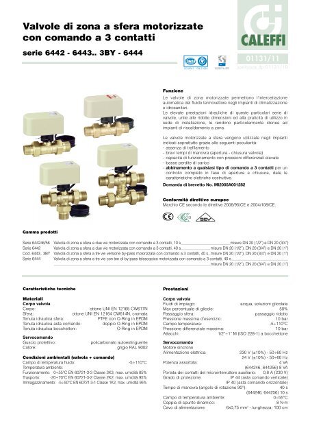
Valvole di zona a sfera motorizzate con comando a 3 contatti - Caleffi
Valvole di zona a sfera motorizzate con comando a 3 contatti - Caleffi
Valvole di zona a sfera motorizzate con comando a 3 contatti - Caleffi

Create successful ePaper yourself
Turn your PDF publications into a flip-book with our unique Google optimized e-Paper software.
<strong>Valvole</strong> <strong>di</strong> <strong>zona</strong> a <strong>sfera</strong> <strong>motorizzate</strong><br />
<strong>con</strong> <strong>comando</strong> a 3 <strong>con</strong>tatti<br />
serie 6442 - 6443.. 3BY - 6444<br />
Gamma prodotti<br />
CALEFFI<br />
01131/11<br />
sostituisce dp 01131/10<br />
Funzione<br />
Le valvole <strong>di</strong> <strong>zona</strong> <strong>motorizzate</strong> permettono l'intercettazione<br />
automatica del fluido termovettore negli impianti <strong>di</strong> climatizzazione<br />
e idrosanitari.<br />
Le elevate prestazioni idrauliche <strong>di</strong> queste particolari serie <strong>di</strong><br />
valvole, unite alle ridotte <strong>di</strong>mensioni ed alla praticità <strong>di</strong> utilizzo in<br />
sede <strong>di</strong> installazione, le rendono particolarmente idonee ad<br />
impianti <strong>di</strong> riscaldamento a <strong>zona</strong>.<br />
Le valvole <strong>motorizzate</strong> a <strong>sfera</strong> vengono utilizzate negli impianti<br />
in<strong>di</strong>cati soprattutto grazie alle seguenti peculiarità:<br />
- assenza <strong>di</strong> trafilamento<br />
- brevi tempi <strong>di</strong> manovra (apertura - chiusura valvola)<br />
- capacità <strong>di</strong> funzionamento <strong>con</strong> pressioni <strong>di</strong>fferenziali elevate<br />
- basse per<strong>di</strong>te <strong>di</strong> carico<br />
- abbinamento a qualsiasi tipo <strong>di</strong> <strong>comando</strong> a 3 <strong>con</strong>tatti per un<br />
<strong>con</strong>trollo completo in fase <strong>di</strong> apertura e chiusura, date le<br />
caratteristiche elettriche costruttive.<br />
Domanda <strong>di</strong> brevetto No. MI2005A001282<br />
Conformità <strong>di</strong>rettive europee<br />
Marchio CE se<strong>con</strong>do le <strong>di</strong>rettive 2006/95/CE e 2004/108/CE.<br />
Serie 644246/56 Valvola <strong>di</strong> <strong>zona</strong> a <strong>sfera</strong> a due vie motorizzata <strong>con</strong> <strong>comando</strong> a 3 <strong>con</strong>tatti, 10 s misure DN 20 (1/2”) e DN 20 (3/4”)<br />
Serie 6442 Valvola <strong>di</strong> <strong>zona</strong> a <strong>sfera</strong> a due vie motorizzata <strong>con</strong> <strong>comando</strong> a 3 <strong>con</strong>tatti, 40 s misure DN 20 (1/2”), DN 20 (3/4”) e DN 20 (1”)<br />
Cod. 6443.. 3BY Valvola <strong>di</strong> <strong>zona</strong> a <strong>sfera</strong> a tre vie versione by-pass motorizzata <strong>con</strong> <strong>comando</strong> a 3 <strong>con</strong>tatti, 40 s misure DN 20 (1/2”), DN 20 (3/4”) e DN 20 (1”)<br />
Serie 6444 Valvola <strong>di</strong> <strong>zona</strong> a <strong>sfera</strong> a tre vie <strong>con</strong> tee <strong>di</strong> by-pass telescopico motorizzata <strong>con</strong> <strong>comando</strong> a 3 <strong>con</strong>tatti, 40 s<br />
misure DN 20 (1/2”), DN 20 (3/4”) e DN 20 (1”)<br />
Caratteristiche tecniche<br />
Materiali<br />
Corpo valvola<br />
Corpo: ottone UNI EN 12165 CW617N<br />
Sfera: ottone UNI EN 12164 CW614N, cromata<br />
Tenuta idraulica <strong>sfera</strong>: PTFE <strong>con</strong> O-Ring in EPDM<br />
Tenuta idraulica asta <strong>comando</strong>: doppio O-Ring in EPDM<br />
Tenuta idraulica bocchettoni: O-Ring in EPDM<br />
Servo<strong>comando</strong><br />
Guscio protettivo: policarbonato autoestinguente<br />
Colore: grigio RAL 9002<br />
Con<strong>di</strong>zioni ambientali (valvola + <strong>comando</strong>)<br />
Campo <strong>di</strong> temperatura fluido: -5÷110°C<br />
Temperatura ambiente:<br />
Funzionamento: 0÷55°C EN 60721-3-3 Classe 3K3, max. umi<strong>di</strong>tà 85%<br />
Trasporto: -20÷70°C EN 60721-3-2 Classe 2K2, max. umi<strong>di</strong>tà 95%<br />
Immagazzinamento: -5÷50°C EN 60721-3-1 Classe 1K2, max. umi<strong>di</strong>tà 95%<br />
Prestazioni<br />
Corpo valvola<br />
Flui<strong>di</strong> <strong>di</strong> impiego: acqua, soluzioni glicolate<br />
Max percentuale <strong>di</strong> glicole: 50%<br />
Passaggio <strong>sfera</strong>: passaggio ridotto<br />
Pressione massima d’esercizio: 10 bar<br />
Campo temperatura: -5÷110°C<br />
Pressione <strong>di</strong>fferenziale massima: 10 bar<br />
Attacchi: 1/2”÷1” M (ISO 228-1) a bocchettone<br />
Servo<strong>comando</strong><br />
Motore sincrono<br />
Alimentazione elettrica: 230 V (±10%) - 50÷60 Hz<br />
24 V (±10%) - 50÷60 Hz<br />
Potenza assorbita: 4 VA<br />
(644246, 644256) 8 VA<br />
Portata dei <strong>con</strong>tatti del microinterruttore ausiliario: 0,8 A (230 V)<br />
Grado <strong>di</strong> protezione: IP 44 (asta <strong>comando</strong> verticale)<br />
IP 40 (asta <strong>comando</strong> orizzontale)<br />
Tempo <strong>di</strong> manovra (angolo <strong>di</strong> rotazione 90°): 40 s<br />
(644246, 644256) 10 s<br />
Campo <strong>di</strong> temperatura ambiente: 0÷55°C<br />
Coppia <strong>di</strong> spunto <strong>di</strong>namico: 8 N·m<br />
Cavo <strong>di</strong> alimentazione: 6x0,75 mm 2 - lunghezza: 100 cm
Dimensioni<br />
Completamento co<strong>di</strong>ce (.)<br />
2 ➙ 230 V 4 ➙ 24 V<br />
Serie 6442<br />
2 vie<br />
Cod. 6443.. 3BY<br />
3 vie versione<br />
by-pass<br />
Serie 6444<br />
3 vie <strong>con</strong><br />
by-pass<br />
telescopico<br />
49<br />
63
Particolarità costruttive<br />
Tenute<br />
Le valvole sono dotate<br />
<strong>di</strong> bocchettoni a sede<br />
piana <strong>con</strong> O-Ring <strong>di</strong><br />
tenuta in EPDM.<br />
Servo<strong>comando</strong><br />
· Utilizzo ON/OFF<br />
Le valvole possono essere utilizzate in modalità ON/OFF <strong>con</strong><br />
<strong>con</strong>senso elettrico <strong>di</strong> apertura o chiusura dato da<br />
termostato/cronotermostato a tre <strong>con</strong>tatti o un comune deviatore.<br />
· Utilizzo modulante<br />
Le caratteristiche elettriche costruttive del servo<strong>comando</strong> lo<br />
rendono abbinabile a qualsiasi tipo <strong>di</strong> regolatore a tre punti.<br />
· Trasmissione del moto<br />
Grazie all’accoppiamento<br />
<strong>con</strong>ico tra l’asta della valvola (1)<br />
e l’albero del motoriduttore (2),<br />
si ottiene un innesto costante dei<br />
due componenti. Ciò permette<br />
una compensazione automatica<br />
del gioco meccanico grazie alla<br />
spinta (S) sull’asta esercitata<br />
dalla pressione del fluido.<br />
· Accoppiamento<br />
servo<strong>comando</strong> valvola<br />
Per mezzo <strong>di</strong> un fermo elastico<br />
<strong>di</strong> bloccaggio in acciaio (3),<br />
l’accoppiamento tra valvola e<br />
servo<strong>comando</strong> risulta agevole<br />
e rapido me<strong>di</strong>ante una<br />
semplice operazione ad innesto<br />
<strong>con</strong> bloccaggio automatico.<br />
· Camma e microinterruttori <strong>di</strong> fine corsa<br />
La camma (4) che aziona<br />
i microinterruttori <strong>di</strong> fine<br />
corsa (5) può muoversi in<br />
5 4<br />
5 6<br />
senso verticale ed è<br />
supportata da una molla<br />
<strong>con</strong>ica (6). In questo<br />
modo si mantiene<br />
costante il <strong>con</strong>tatto<br />
<strong>con</strong> i microinterruttori<br />
compensando l’eventuale<br />
usura dei particolari nel<br />
tempo.<br />
· Microinterruttore ausiliario<br />
Il servo<strong>comando</strong> è dotato <strong>di</strong> microinterruttore ausiliario da<br />
utilizzare, ad esempio, per l’arresto della pompa alla chiusura<br />
della valvola e viceversa.<br />
Esso si chiude per un valore me<strong>di</strong>o <strong>di</strong> apertura valvola dell’80%.<br />
Valvola a tre vie <strong>con</strong> tee telescopico e ugello calibrato<br />
La valvola a tre vie <strong>con</strong> tee <strong>di</strong> by-pass<br />
telescopico serie 6444 permette<br />
l’accoppiamento <strong>con</strong> collettori aventi interasse<br />
principale compreso tre i 49 ed i 63 mm.<br />
Il tee <strong>di</strong> by-pass è dotato <strong>di</strong> ugello calibrato<br />
U6 (7), avente lo scopo <strong>di</strong> creare per<strong>di</strong>te <strong>di</strong><br />
carico equivalenti a quelle del circuito <strong>di</strong><br />
utilizzazione. Questo sistema permette <strong>di</strong><br />
mantenere costante la portata nell’impianto e<br />
quin<strong>di</strong> la prevalenza della pompa, tanto <strong>con</strong><br />
valvola aperta, quanto <strong>con</strong> valvola in by-pass.<br />
➡<br />
➡<br />
2<br />
3<br />
1<br />
S<br />
7<br />
Direzioni <strong>di</strong> flusso ed in<strong>di</strong>catore posizione<br />
Rimuovendo il servo<strong>comando</strong>, risulta visibile l’intaglio sulla sommità<br />
dell’asta <strong>di</strong> <strong>comando</strong> su cui agisce il perno del servomotore:<br />
- esso <strong>con</strong>sente la manovra <strong>di</strong> apertura/chiusura della valvola<br />
agendo manualmente <strong>con</strong> un cacciavite.<br />
- la sua posizione permette <strong>di</strong> capire la <strong>di</strong>rezione del flusso in<br />
funzione della posizione della <strong>sfera</strong>, in<strong>di</strong>cazione particolarmente<br />
utile in sede <strong>di</strong> collaudo o <strong>di</strong> verifica dell’impianto.<br />
A seguire sono proposti tre schemi, ognuno per tipologia <strong>di</strong><br />
valvola; a se<strong>con</strong>da della posizione dell’intaglio viene in<strong>di</strong>cata la<br />
<strong>di</strong>rezione del flusso.<br />
Valvola a due vie serie 6442<br />
Valvola a tre vie versione by-pass co<strong>di</strong>ce 6443.. 3BY<br />
Valvola a tre vie <strong>con</strong> tee <strong>di</strong> by pass serie 6444<br />
CALEFFI<br />
CALEFFI<br />
Tutte le valvole vengono fornite <strong>con</strong> l’intaglio/in<strong>di</strong>catore in posizione orizzontale.<br />
CALEFFI<br />
CALEFFI
Caratteristiche idrauliche<br />
Valvola <strong>di</strong> <strong>zona</strong> a due vie serie 6442, misure 1/2”, 3/4” e 1”<br />
∆p (mm c.a.)<br />
4000<br />
2000<br />
1000<br />
500<br />
200<br />
100<br />
50<br />
20<br />
10<br />
Kv (m 3 /h) = 11,1<br />
Valvola <strong>di</strong> <strong>zona</strong> a tre vie versione by-pass co<strong>di</strong>ce 6443.. 3BY<br />
in funzionamento “aperto”, misure 1/2”, 3/4”, 1”<br />
∆p (mm c.a.)<br />
∆p (kPa)<br />
4000<br />
2000<br />
1000<br />
500<br />
200<br />
100<br />
50<br />
20<br />
10<br />
3000<br />
1800<br />
1600<br />
1400<br />
1200<br />
900<br />
800<br />
700<br />
600<br />
400<br />
300<br />
180<br />
160<br />
140<br />
120<br />
90<br />
80<br />
70<br />
60<br />
40<br />
30<br />
18<br />
16<br />
14<br />
12<br />
300 350<br />
Kv (m 3 /h) = 10,3<br />
40<br />
45<br />
500<br />
600<br />
700<br />
800<br />
900<br />
1000<br />
1200<br />
1400<br />
1600<br />
1800<br />
2000<br />
2500<br />
3000<br />
3500<br />
4000<br />
4500<br />
5000<br />
6000<br />
7000<br />
8000<br />
9000<br />
10000<br />
G (l/h)<br />
Valvola <strong>di</strong> <strong>zona</strong> a tre vie versione by-pass co<strong>di</strong>ce 6443.. 3BY<br />
in funzionamento “by-pass”, misure 1/2”, 3/4”, 1”<br />
∆p (mm c.a.) ∆p (kPa)<br />
2000<br />
1800<br />
1600<br />
1400<br />
1200<br />
1000 900<br />
800<br />
700<br />
600<br />
500<br />
200<br />
180<br />
160<br />
140<br />
120<br />
100<br />
90<br />
80<br />
70<br />
Kv (m 3 /h) = 1,8<br />
100<br />
200<br />
500<br />
1000<br />
G (l/h)<br />
30<br />
18<br />
16<br />
14<br />
12<br />
9<br />
8<br />
7<br />
6<br />
5000 50<br />
50<br />
3000<br />
1800<br />
1600<br />
1400<br />
1200<br />
900<br />
800<br />
700<br />
600<br />
400<br />
300<br />
180<br />
160<br />
140<br />
120<br />
90<br />
80<br />
70<br />
60<br />
40<br />
30<br />
18<br />
16<br />
14<br />
12<br />
4000 40<br />
3000<br />
30<br />
400<br />
300<br />
300 350<br />
60<br />
50<br />
40<br />
45<br />
500<br />
600<br />
700<br />
800<br />
CALEFFI<br />
CALEFFI<br />
60<br />
70<br />
80<br />
90<br />
120<br />
140<br />
160<br />
180<br />
900<br />
1000<br />
1200<br />
1400<br />
1600<br />
1800<br />
2000<br />
250<br />
300<br />
350<br />
400<br />
450<br />
2500<br />
3000<br />
3500<br />
4000<br />
4500<br />
5000<br />
6000<br />
7000<br />
8000<br />
9000<br />
10000<br />
600<br />
700<br />
800<br />
900<br />
G (l/h)<br />
1200<br />
1400<br />
1600<br />
1800<br />
∆p (kPa)<br />
2000<br />
30<br />
18<br />
16<br />
14<br />
12<br />
9<br />
8<br />
7<br />
6<br />
4<br />
3<br />
1,8<br />
1,6<br />
1,4<br />
1,2<br />
0,9<br />
0,8<br />
0,7<br />
0,6<br />
0,4<br />
0,3<br />
4<br />
3<br />
1,8<br />
1,6<br />
1,4<br />
1,2<br />
0,9<br />
0,8<br />
0,7<br />
0,6<br />
0,4<br />
0,3<br />
40<br />
20<br />
10<br />
0,18<br />
0,16<br />
0,14<br />
0,12<br />
16<br />
18<br />
14<br />
12<br />
9<br />
8<br />
7<br />
6<br />
4<br />
3<br />
5<br />
2<br />
1<br />
20<br />
10<br />
0,5<br />
0,2<br />
0,1<br />
5<br />
2<br />
1,8<br />
1,6<br />
1,4<br />
1,2<br />
0,9 1<br />
0,8<br />
0,7<br />
0,6<br />
40<br />
20<br />
10<br />
0,18<br />
0,16<br />
0,14<br />
0,12<br />
5<br />
2<br />
1<br />
0,5<br />
0,2<br />
0,1<br />
0,5<br />
Valvola <strong>di</strong> <strong>zona</strong> a tre vie <strong>con</strong> tee <strong>di</strong> by-pass serie 6444 in<br />
funzionamento “aperto”, misure 1/2”, 3/4”, 1”<br />
∆p (mm c.a.)<br />
∆p (kPa)<br />
4000<br />
2000<br />
1000<br />
500<br />
200<br />
100<br />
50<br />
20<br />
10<br />
Kv (m 3 /h) = 10,3<br />
Valvola <strong>di</strong> <strong>zona</strong> a tre vie serie 6444 in funzionamento “by-pass”<br />
provvista <strong>di</strong> ugello U6, misure 1/2”, 3/4”, 1”<br />
∆p (mm c.a.) ∆p (kPa)<br />
5000 50<br />
2000<br />
1800<br />
1600<br />
1400<br />
1200<br />
1000 900<br />
800<br />
700<br />
4000 40<br />
3000<br />
30<br />
600<br />
500<br />
400<br />
300<br />
200<br />
180<br />
160<br />
140<br />
120<br />
100<br />
90<br />
80<br />
70<br />
50<br />
3000<br />
1800<br />
1600<br />
1400<br />
1200<br />
900<br />
800<br />
700<br />
600<br />
400<br />
300<br />
180<br />
160<br />
140<br />
120<br />
90<br />
80<br />
70<br />
60<br />
40<br />
30<br />
18<br />
16<br />
14<br />
12<br />
300<br />
350<br />
40<br />
45<br />
60<br />
50<br />
60<br />
70<br />
80<br />
90<br />
Kv (m 3 /h) = 1,2<br />
CALEFFI<br />
500<br />
600<br />
700<br />
800<br />
900<br />
1000<br />
1200<br />
1400<br />
1600<br />
1800<br />
2000<br />
CALEFFI<br />
100<br />
120<br />
140<br />
160<br />
180<br />
200<br />
250<br />
300<br />
350<br />
400<br />
450<br />
2500<br />
3000<br />
500<br />
3500<br />
4000<br />
4500<br />
5000<br />
6000<br />
7000<br />
8000<br />
9000<br />
10000<br />
600<br />
700<br />
800<br />
900<br />
1000<br />
G (l/h)<br />
1200<br />
1400<br />
1600<br />
1800<br />
2000<br />
G (l/h)<br />
30<br />
18<br />
16<br />
14<br />
12<br />
9<br />
8<br />
7<br />
6<br />
4<br />
3<br />
1,8<br />
1,6<br />
1,4<br />
1,2<br />
0,9<br />
0,8<br />
0,7<br />
0,6<br />
0,4<br />
0,3<br />
16<br />
18<br />
14<br />
12<br />
9<br />
8<br />
7<br />
6<br />
4<br />
3<br />
20<br />
10<br />
5<br />
2<br />
1,8<br />
1,6<br />
1,4<br />
1,2<br />
0,9 1<br />
0,8<br />
0,7<br />
0,6<br />
40<br />
20<br />
10<br />
0,18<br />
0,16<br />
0,14<br />
0,12<br />
5<br />
2<br />
1<br />
0,5<br />
0,2<br />
0,1<br />
0,5
�� � ���<br />
��<br />
�� ���<br />
�� � �<br />
����<br />
��<br />
���<br />
relè N.C.<br />
230 V<br />
N<br />
INTERRUTTORE DI COMMUTAZIONE ON/OFF<br />
L<br />
Installazione<br />
Schemi elettrici<br />
1. La valvola a due vie può<br />
1. Schema <strong>di</strong> collegamento termostato ambiente (TA) ed<br />
essere installata sia sulla<br />
alimentazione elettrica.<br />
tubazione <strong>di</strong> andata che su<br />
Il collegamento illustrato <strong>con</strong>sente l’apertura e chiusura della<br />
quella <strong>di</strong> ritorno.<br />
valvola su <strong>con</strong>senso del termostato ambiente a tre <strong>con</strong>tatti.<br />
ATTUATORE<br />
Max<br />
ATTUATORE<br />
0,8 A<br />
M<br />
Max<br />
0,8 A<br />
M<br />
2. Le valvole a tre vie versione<br />
by-pass e a tre vie <strong>con</strong> tee<br />
<strong>di</strong> by-pass devono essere<br />
installate sulla tubazione <strong>di</strong><br />
mandata<br />
N<br />
TA<br />
L<br />
relè N.C.<br />
230 V<br />
3. La valvola va installata<br />
2. Schema <strong>di</strong> collegamento N <strong>con</strong> interruttore INTERRUTTORE <strong>di</strong> commutazione DI COMMUTAZIONE ON/OFF<br />
<strong>con</strong> l’asta <strong>di</strong> <strong>comando</strong><br />
Il collegamento L illustrato <strong>con</strong>sente l’apertura e chiusura della<br />
in posizione orizzontale<br />
valvola su <strong>con</strong>senso dell’interruttore tramite l’uso <strong>di</strong> un relè<br />
oppure verticale, mai in<br />
interme<strong>di</strong>o.<br />
posizione rovesciata.<br />
Asta orizzontale Asta verticale<br />
ATTUATORE<br />
ATTUATORE Max<br />
3b. Nel caso <strong>di</strong> installazioni <strong>con</strong> acqua refrigerata, <strong>con</strong><br />
0,8 A<br />
rischio formazione <strong>con</strong>densa, il servo<strong>comando</strong><br />
M Max<br />
0,8 A<br />
deve essere installato <strong>con</strong> asta <strong>di</strong> <strong>comando</strong> verticale.<br />
M<br />
ATTUATORE<br />
Max<br />
0,8 A<br />
4. Il servo<strong>comando</strong> può<br />
M<br />
essere montato sul corpo<br />
valvola nelle due posizioni<br />
in<strong>di</strong>cate. Il fissaggio è<br />
effettuato me<strong>di</strong>ante un<br />
relè N.C.<br />
230 V<br />
fermo elastico in acciaio<br />
N<br />
inox.<br />
TA<br />
L<br />
N<br />
INTERRUTTORE DI COMMUTAZIONE ON/OFF<br />
L<br />
N<br />
TA<br />
L<br />
5. Nell’installazione in cassetta<br />
3. Schema <strong>di</strong>sinserimento pompa quando nessuna <strong>zona</strong><br />
lasciare uno spazio <strong>di</strong> almeno min. 30 mm<br />
risulta in funzione.<br />
30 mm tra servo<strong>comando</strong> e telaio<br />
Lo schema proposto, utilizzando il microinterruttore ausiliario,<br />
per un’eventuale sostituzione o<br />
<strong>con</strong>sente il <strong>di</strong>sinserimento della pompa quando la valvola<br />
manutenzione.<br />
<strong>di</strong> <strong>zona</strong> è chiusa.<br />
Qualora la pompa avesse un assorbimento superiore a 0,8 A<br />
ATTUATORE<br />
(170 VA) è necessario utilizzare un teleruttore interme<strong>di</strong>o.<br />
min. 30 mm<br />
Max<br />
0,8 A<br />
M<br />
ATTUATORE<br />
Max<br />
CALEFFI<br />
0,8 A<br />
M<br />
N<br />
TA<br />
L<br />
N<br />
6. Per impe<strong>di</strong>re il raggiungimento <strong>di</strong> temperature<br />
TA<br />
elevate, dove è installata la valvola <strong>di</strong> <strong>zona</strong> è<br />
L<br />
opportuno che vi sia una costante<br />
circolazione <strong>di</strong> aria.<br />
Microinterruttori<br />
Il motore elettrico è dotato <strong>di</strong> microinterruttori <strong>di</strong> fine corsa che<br />
interrompono l’alimentazione elettrica al raggiungimento delle<br />
posizioni <strong>di</strong> apertura/chiusura completa della valvola.<br />
ATTUATORE<br />
Il microinterruttore ausiliario è un <strong>di</strong>spositivo aggiuntivo utilizzabile<br />
Max<br />
per l’attivazione/<strong>di</strong>sattivazione <strong>di</strong> componenti 0,8 A (quali pompe, caldaie,<br />
ecc.) rispettivamente in fase M <strong>di</strong> apertura o chiusura della valvola. Il<br />
<strong>con</strong>tatto si chiude per un valore me<strong>di</strong>o <strong>di</strong> apertura valvola dell’80%<br />
C A L E F F I<br />
C A L E F F I<br />
C A L E F F I<br />
C A L E F F I<br />
356<br />
CALEFFI<br />
C A L E F F I C A L E F F I C A L E F F I C A L E F F I<br />
C A L E F F I<br />
C A L E F F I<br />
C A L E F F I<br />
356<br />
C A L E F F I<br />
C A L E F F I<br />
C A L E F F I<br />
C A L E F F I<br />
C A L E F F I<br />
CALEFFI<br />
356<br />
C A L E F F I C A L E F F I C A L E F F I C A L E F F I<br />
�� �� ���<br />
��<br />
��<br />
�<br />
C A L E F F I<br />
C A L E F F I<br />
C A L E F F I<br />
L N<br />
OPEN<br />
CLOSE<br />
C A L E F F I��<br />
Max<br />
0,8 A M<br />
CALEFFI<br />
UTENZA UTENZA<br />
UTENZA UTENZA<br />
UTENZA UTENZA<br />
UTENZA UTENZA<br />
C A L E F F I C A L E F F I C A L E F F I C A L E F F I<br />
CHIUDE<br />
CHIUDE<br />
APRE<br />
APRE<br />
CHIUDE<br />
CHIUDE CHIUDE<br />
CHIUDE<br />
CHIUDE<br />
APRE<br />
APRE<br />
APRE<br />
APRE<br />
APRE<br />
CHIUDE<br />
APRE
Schemi applicativi<br />
Negli impianti <strong>con</strong> regolazione <strong>di</strong> <strong>zona</strong>, si agisce in modo tale da intercettare automaticamente i circuiti idraulici al servizio dei terminali <strong>di</strong><br />
scambio termico, in funzione della temperatura raggiunta in ambiente. Tale chiusura dei circuiti può però provocare variazioni <strong>di</strong> pressione e<br />
portata in tutto l’impianto, per cui è in<strong>di</strong>spensabile fare in modo che queste variazioni siano tenute sotto <strong>con</strong>trollo entro limiti accettabili.<br />
Impianto <strong>con</strong> valvole <strong>di</strong> <strong>zona</strong> a due vie, valvola <strong>di</strong> sfioro e AUTOFLOW ® , serie 6442.<br />
L’impianto funziona a portata variabile e si deve necessariamente tenere sotto <strong>con</strong>trollo l’incremento <strong>di</strong> pressione <strong>di</strong>fferenziale generato dalla<br />
chiusura delle valvole <strong>di</strong> <strong>zona</strong>. Tale incremento, che può raggiungere limiti inaccettabili per il buon funzionamento del sistema, si traduce in un<br />
aumento della portata ai circuiti rimasti aperti, <strong>con</strong> problemi alle pompe ed alla caldaia. Occorre pertanto tenere sotto <strong>con</strong>trollo le pressioni<br />
<strong>di</strong>fferenziali me<strong>di</strong>ante valvole <strong>di</strong> by-pass <strong>di</strong>fferenziali o pompe a velocità variabile. Me<strong>di</strong>ante l’inserimento dell’AUTOFLOW ® , si limita comunque<br />
sempre la portata ai circuiti aperti al valore nominale.<br />
TA<br />
Valvola intercettazione<br />
Valvola termostatica<br />
Valvola manuale<br />
Elettropompa<br />
AUTOFLOW ®<br />
Termostato ambiente<br />
By-pass <strong>di</strong>fferenziale<br />
Valvola sfogo aria<br />
Valvola <strong>di</strong> sfioro<br />
Impianto <strong>con</strong> valvola <strong>di</strong> <strong>zona</strong> a tre vie versione by-pass, co<strong>di</strong>ce 6443.. 3BY<br />
CALEFFI<br />
CALEFFI<br />
TA<br />
TA<br />
TA
Impianto <strong>con</strong> valvole <strong>di</strong> <strong>zona</strong> a tre vie <strong>con</strong> tee <strong>di</strong> by-pass e AUTOFLOW ® , serie 6444<br />
Impianto autonomo <strong>con</strong> valvole <strong>di</strong> <strong>zona</strong> a tre vie <strong>con</strong> tee <strong>di</strong> by-pass e AUTOFLOW ® , serie 6444<br />
CALEFFI CALEFFI<br />
CALEFFI<br />
TA<br />
TA<br />
TA
TESTO DI CAPITOLATO<br />
Cod. 644246/56<br />
Valvola <strong>di</strong> <strong>zona</strong> a <strong>sfera</strong> motorizzata a due vie <strong>con</strong> <strong>comando</strong> a tre <strong>con</strong>tatti. Misura DN 20. Attachi 1/2” (1/2” e 3/4”) M<br />
(ISO 228-1) a bocchettone. Corpo in ottone. Sfera in ottone, cromata. Tenuta idraulica <strong>sfera</strong> in PTFE <strong>con</strong> O-Ring in EPDM.<br />
Tenuta idraulica asta <strong>di</strong> <strong>comando</strong> <strong>con</strong> doppio O-Ring in EPDM. Tenute idrauliche bocchettone <strong>con</strong> O-Ring in EPDM. Flui<strong>di</strong><br />
d'impiego acqua e soluzioni glicolate; massima percentuale <strong>di</strong> glicole 50%. Pressione massima <strong>di</strong> esercizio 10 bar.<br />
Campo <strong>di</strong> temperatura <strong>di</strong> esercizio -5÷110°C. Pressione massima <strong>di</strong>fferenziale <strong>di</strong> funzionamento 10 bar. Servo<strong>comando</strong><br />
in policarbonato autoestinguente; colore grigio RAL 9002; motore sincrono a tre <strong>con</strong>tatti <strong>con</strong> microinterruttore ausiliario;<br />
alimentazione elettrica 230 V (o 24 V); potenza assorbita 8 VA; coppia <strong>di</strong> spunto <strong>di</strong>namico 8 N·m. Portata <strong>con</strong>tatti micro<br />
ausiliario 0,8 A. Classe <strong>di</strong> protezione IP 44 <strong>con</strong> asta <strong>di</strong> <strong>comando</strong> in posizione verticale, IP 40 <strong>con</strong> asta <strong>di</strong> <strong>comando</strong> in<br />
posizione orizzontale. Tempo <strong>di</strong> manovra 10 s; campo <strong>di</strong> temperatura ambiente 0÷55°C.<br />
Serie 6442<br />
Valvola <strong>di</strong> <strong>zona</strong> a <strong>sfera</strong> motorizzata a due vie <strong>con</strong> <strong>comando</strong> a tre <strong>con</strong>tatti. Misura DN 20. Attachi 1/2” (da 1/2” a 1”) M<br />
(ISO 228-1) a bocchettone. Corpo in ottone. Sfera in ottone, cromata. Tenuta idraulica <strong>sfera</strong> in PTFE <strong>con</strong> O-Ring in EPDM.<br />
Tenuta idraulica asta <strong>di</strong> <strong>comando</strong> <strong>con</strong> doppio O-Ring in EPDM. Tenute idrauliche bocchettone <strong>con</strong> O-Ring in EPDM. Flui<strong>di</strong><br />
d'impiego acqua e soluzioni glicolate; massima percentuale <strong>di</strong> glicole 50%. Pressione massima <strong>di</strong> esercizio 10 bar.<br />
Campo <strong>di</strong> temperatura <strong>di</strong> esercizio -5÷110°C. Pressione massima <strong>di</strong>fferenziale <strong>di</strong> funzionamento 10 bar. Servo<strong>comando</strong><br />
in policarbonato autoestinguente; colore grigio RAL 9002; motore sincrono a tre <strong>con</strong>tatti <strong>con</strong> microinterruttore ausiliario;<br />
alimentazione elettrica 230 V (o 24 V); potenza assorbita 4 VA (644246, 644256) 8 VA; coppia <strong>di</strong> spunto <strong>di</strong>namico 8 N·m.<br />
Portata <strong>con</strong>tatti micro ausiliario 0,8 A. Classe <strong>di</strong> protezione IP 44 <strong>con</strong> asta <strong>di</strong> <strong>comando</strong> in posizione verticale, IP 40 <strong>con</strong><br />
asta <strong>di</strong> <strong>comando</strong> in posizione orizzontale. Tempo <strong>di</strong> manovra (angolo <strong>di</strong> rotazione 90°C) 40 s, (644246, 644256) 10 s;<br />
campo <strong>di</strong> temperatura ambiente 0÷55°C.<br />
Cod. 6443.. 3BY<br />
Valvola <strong>di</strong> <strong>zona</strong> a <strong>sfera</strong> a tre vie versione by-pass motorizzata <strong>con</strong> <strong>comando</strong> a tre <strong>con</strong>tatti. Misura DN 20. Attachi 1/2” (da<br />
1/2” a 1”) M (ISO 228-1) a bocchettone. Corpo in ottone. Sfera in ottone, cromata. Tenuta idraulica <strong>sfera</strong> in PTFE <strong>con</strong> O-<br />
Ring in EPDM. Tenuta idraulica asta <strong>di</strong> <strong>comando</strong> <strong>con</strong> doppio O-Ring in EPDM. Tenute idrauliche bocchettone <strong>con</strong> O-Ring<br />
in EPDM. Flui<strong>di</strong> d’impiego acqua e soluzioni glicolate; massima percentuale <strong>di</strong> glicole 50%. Pressione massima <strong>di</strong><br />
esercizio 10 bar. Campo <strong>di</strong> temperatura <strong>di</strong> esercizio -5÷110°C. Pressione massima <strong>di</strong>fferenziale <strong>di</strong> funzionamento 10 bar.<br />
Servo<strong>comando</strong> in policarbonato autoestinguente; colore grigio RAL 9002; motore sincrono a tre <strong>con</strong>tatti <strong>con</strong><br />
microinterruttore ausiliario; alimentazione elettrica 230 V (o 24 V); potenza assorbita 4 VA; coppia <strong>di</strong> spunto <strong>di</strong>namico<br />
8 N·m. Portata <strong>con</strong>tatti micro ausiliario 0,8 A. Classe <strong>di</strong> protezione IP 44 <strong>con</strong> asta <strong>di</strong> <strong>comando</strong> in posizione verticale<br />
IP 40 <strong>con</strong> asta <strong>di</strong> <strong>comando</strong> in posizione orizzontale. Tempo <strong>di</strong> manovra (angolo <strong>di</strong> rotazione 90°C) 40 s; campo <strong>di</strong><br />
temperatura ambiente 0÷55°C.<br />
Serie 6444<br />
Valvola <strong>di</strong> <strong>zona</strong> a <strong>sfera</strong> a tre vie <strong>con</strong> tee <strong>di</strong> by-pass telescopico motorizzata <strong>con</strong> <strong>comando</strong> a tre <strong>con</strong>tatti. Misura DN 20.<br />
Attachi 1/2” (da 1/2” a 1”) M (ISO 228-1) a bocchettone. Corpo in ottone. Sfera in ottone, cromata. Tenuta idraulica <strong>sfera</strong><br />
in PTFE <strong>con</strong> O-Ring in EPDM. Tenuta idraulica asta <strong>di</strong> <strong>comando</strong> <strong>con</strong> doppio O-Ring in EPDM. Tenute idrauliche<br />
bocchettone <strong>con</strong> O-Ring in EPDM. Flui<strong>di</strong> d’impiego acqua e soluzioni glicolate; massima percentuale <strong>di</strong> glicole 50%.<br />
Pressione massima <strong>di</strong> esercizio 10 bar. Corredata <strong>di</strong> ugello calibrato (U6) sulla terza via, per il bilanciamento<br />
dell’impianto. Campo <strong>di</strong> temperatura <strong>di</strong> esercizio -5÷110°C. Pressione massima <strong>di</strong>fferenziale <strong>di</strong> funzionamento 10 bar.<br />
Interasse tra gli attacchi regolabile da 49 a 63 mm. Servo<strong>comando</strong> in policarbonato autoestinguente; colore grigio RAL<br />
9002; motore sincrono a tre <strong>con</strong>tatti <strong>con</strong> microinterruttore ausiliario; alimentazione elettrica 230 V (o 24 V); potenza<br />
assorbita 4 VA; coppia <strong>di</strong> spunto <strong>di</strong>namico 8 N·m. Portata <strong>con</strong>tatti micro ausiliario 0,8 A. Classe <strong>di</strong> protezione IP 44 <strong>con</strong><br />
asta <strong>di</strong> <strong>comando</strong> in posizione verticale IP 40 <strong>con</strong> asta <strong>di</strong> <strong>comando</strong> in posizione orizzontale. Tempo <strong>di</strong> manovra (angolo<br />
<strong>di</strong> rotazione 90°C) 40 s; campo <strong>di</strong> temperatura ambiente 0÷55°C.<br />
Ci riserviamo il <strong>di</strong>ritto <strong>di</strong> apportare miglioramenti e mo<strong>di</strong>fiche ai prodotti descritti ed ai relativi dati tecnici in qualsiasi momento e senza preavviso.<br />
CALEFFI<br />
CALEFFI S.p.A. · S.R.229, N.25 · 28010 Fontaneto d’Agogna (NO) · Italia · Tel. +39 0322 8491 · Fax +39 0322 863305<br />
· www.caleffi.it · info@caleffi.it ·<br />
© Copyright 2011 <strong>Caleffi</strong>


