FG7OH2R Bassa tensione Low voltage - Prysmian
FG7OH2R Bassa tensione Low voltage - Prysmian
FG7OH2R Bassa tensione Low voltage - Prysmian

You also want an ePaper? Increase the reach of your titles
YUMPU automatically turns print PDFs into web optimized ePapers that Google loves.
Energia e segnalamento / Power and signalling<br />
<strong>Bassa</strong> <strong>tensione</strong><br />
Norma di riferimento<br />
CEI 20-13<br />
Descrizione del cavo<br />
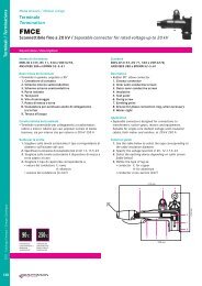
<strong>FG7OH2R</strong><br />
0,6/1 kV<br />
> Anima<br />
Conduttore a corda rotonda flessibile di rame rosso ricotto<br />
> Isolante<br />
Gomma HEPR ad alto modulo, che conferisce al cavo elevate<br />
caratteristiche elettriche, meccaniche e termiche (norme CEI<br />
20-11 - CEI 20-34)<br />
> Colori delle anime<br />
nero<br />
blu chiaro-marrone-nero-grigio<br />
giallo/verde-marrone-nero-grigio<br />
blu chiaro-marrone<br />
Le anime dei cavi per segnalamento sono nere, numerate ed<br />
è previsto il conduttore di terra giallo/verde<br />
> Schermatura<br />
Costituita da treccia di rame rosso<br />
> Guaina<br />
In PVC speciale di qualità Rz, colore grigio<br />
> Marcatura<br />
Stampigliatura ad inchiostro speciale ogni 1 m:<br />
CEI 20-22 II IEMMEQU CEI 20-52 G-SETTE PIU’ PRYSMIAN (G) ECOLOGY LINE<br />
Marcatura metrica progressiva<br />
Caratteristiche del cavo<br />
marrone-nero-grigio<br />
giallo/verde-marrone-blu chiaro<br />
giallo/verde<br />
blu chiaro-marrone-nero-grigio<br />
Conforme ai requisiti essenziali delle direttive BT73/23 e<br />
93/68 CE<br />
> Adatti per alimentazione e trasporto di comandi e/o segnali<br />
nell’industria/artigianato, e nei cantieri. Adatti per posa fissa<br />
sia all’interno, che all’esterno su passerelle, in tubazioni,<br />
canalette o sistemi similari. Possono essere direttamente<br />
interrati<br />
<strong>Low</strong> <strong>voltage</strong><br />
Standard<br />
CEI 20-13<br />
Cable description<br />
> Core<br />
Stranded flexible annealed bare copper conductor<br />
> Insulation<br />
High module HEPR rubber, , with higher electrical, mechanical and thermal<br />
performances (CEI 20-11 - CEI 20-34 standards)<br />
> Core identification<br />
black<br />
light blue-brown-black-grey<br />
yellow/green-brown-black-grey<br />
Signalling cable cores are black, numbered and with yellow/green ground<br />
conductor<br />
> Screen<br />
Red copper braid<br />
> Sheath<br />
Special Rz quality PVC, grey in colour<br />
> Marking<br />
Special ink marking every 1 m:<br />
CEI 20-22 II IEMMEQU CEI 20-52 G-SETTE PIU’ <br />
PRYSMIAN (G) ECOLOGY LINE<br />
Progressive metric marking<br />
Compliant with the requirements of the BT73/23 and 93/68 CE<br />
directives<br />
Cable applications<br />
light blue-brown<br />
brown-black-grey<br />
yellow/green-brown-light blue<br />
yellow/green<br />
light blue-brown-black-grey<br />
> For supply and feeding of power and signals in industry, public applications<br />
and residential buildings. Suitable for fixed installation both indoor and<br />
outdoor, on cable trays, in pipe, conduits or similar systems. Can be<br />
directly buried<br />
90°C<br />
250°C<br />
Pb<br />
TEMPERATURA<br />
FUNZIONAMENTO<br />
OPERATING<br />
TEMPERATURE<br />
TEMPERATURA<br />
CORTOCIRCUITO<br />
SHORT-CIRCUIT<br />
TEMPERATURE<br />
CEI 20-35<br />
EN 60332<br />
CEI 20.22 II CEI 20-37<br />
EN 50267<br />
SENZA<br />
PIOMBO<br />
LEAD<br />
FREE<br />
FLESSIBILE<br />
FLEXIBLE<br />
CONDIZIONI DI POSA<br />
LAYING CONDITIONS<br />
30<br />
TEMPERATURA<br />
MINIMA DI POSA<br />
0 °C<br />
MINIMUM<br />
INSTALLATION<br />
TEMPERATURE<br />
0 °C<br />
TUBO O<br />
CANALINA IN ARIA<br />
DUCT OR<br />
CABLE TRAY<br />
CANALE<br />
INTERRATO<br />
BURIED<br />
TROUGH<br />
TUBO<br />
INTERRATO<br />
BURIED<br />
DUCT<br />
ARIA LIBERA<br />
OPEN AIR<br />
DIRETTAMENTE<br />
INTERRATO<br />
DIRECTLY<br />
BURIED<br />
INTERRATO CON<br />
PROTEZIONE<br />
BURIED<br />
WITH PROTECTION
ISTITUTO ITALIANO<br />
CAVO CONFORME<br />
MARCHIO DI QUALITA'<br />
NORME CEI-UNEL<br />
Ecology<br />
Line TM<br />
<strong>FG7OH2R</strong><br />
sezione<br />
nominale<br />
conductor<br />
cross-section<br />
(mm 2 )<br />
diametro<br />
indicativo<br />
conduttore<br />
approximate<br />
diameter,<br />
conductor of<br />
the phase<br />
core<br />
(mm)<br />
spessore<br />
medio<br />
isolante<br />
average<br />
insulation<br />
thickness<br />
(mm)<br />
diametro<br />
esterno<br />
massimo<br />
maximum<br />
outer<br />
diameter<br />
(mm)<br />
peso<br />
indicativo<br />
del cavo<br />
approximate<br />
weight<br />
(kg/km)<br />
resistenza<br />
massima a<br />
20 °C in c. c.<br />
maximum DC<br />
resistance at<br />
20 °C<br />
(Ω/km)<br />
30 °C in<br />
aria<br />
in open air<br />
at 30 °C<br />
portata di corrente (A) con temperatura ambiente di<br />
30 °C in<br />
20 °C<br />
tubo in aria interrato in tubo<br />
permissible current rating (A)<br />
in duct In buried duct<br />
at 30 °C<br />
at 20 °C<br />
ρ=1 °C m/w ρ=1,5 °C m/w<br />
20 °C<br />
interrato<br />
buried<br />
at 20 °C<br />
ρ=1 °C m/w ρ=1,5 °C m/w<br />
raggio<br />
minimo di<br />
curvatura<br />
minimum<br />
bending<br />
radius<br />
(mm)<br />
2 conduttori tab. CEI-UNEL 35375 2 cores<br />
1,5 1,5 0,7 12,7 190 13,3 26 22 24 23 36 31 85<br />
2,5 1,9 0,7 13,7 240 7,98 36 30 31 30 47 41 95<br />
4 2,4 0,7 14,9 290 4,95 49 40 41 39 61 55 105<br />
6 3 0,7 16,1 360 3,30 63 51 52 49 77 68 110<br />
10 4,1 0,7 18,2 500 1,91 86 69 70 66 105 92 130<br />
16 5,2 0,7 20,4 680 1,21 115 91 92 86 136 120 145<br />
25 6,3 0,9 24 940 0,780 149 119 118 111 177 156 170<br />
35 7,7 0,9 26,6 1230 0,554 185 145 145 136 212 185 190<br />
50 9,4 1 30,5 1700 0,386 225 175 180 168 252 221 200<br />
3 conduttori tab. CEI-UNEL 35375 3 cores<br />
1,5 1,5 0,7 13,3 210 13,3 23 19,5 20 19 30 26 85<br />
2,5 1,9 0,7 14,3 270 7,98 32 26 26 25 40 36 95<br />
4 2,4 0,7 15,6 330 4,95 42 35 33 32 51 45 105<br />
6 3 0,7 16,9 420 3,30 54 44 43 41 65 56 110<br />
10 4,1 0,7 19,2 600 1,91 75 60 59 55 88 78 135<br />
16 5,2 0,7 21,5 820 1,21 100 80 76 72 114 101 155<br />
25 6,3 0,9 25,4 1150 0,780 127 105 100 93 148 130 170<br />
35 7,7 0,9 28,3 1520 0,554 158 128 122 114 178 157 190<br />
50 9,4 1 32,4 2160 0,386 192 154 152 141 211 185 220<br />
70 10,9 1,1 36,8 2920 0,272 246 194 189 174 259 227 225<br />
95 12,7 1,1 41,2 3740 0,206 298 233 226 206 311 274 290<br />
120 14,5 1,2 45,8 4700 0,161 346 268 260 238 355 311 325<br />
150 15,6 1,4 50,9 5800 0,129 399 300 299 272 394 345 340<br />
3 conduttori con giallo/verde tab. CEI-UNEL 35375 3 cores with yellow/green<br />
1,5 1,5 0,7 13,3 210 13,3 26 22 24 23 36 31 85<br />
2,5 1,9 0,7 14,3 270 7,98 36 30 31 30 47 41 95<br />
4 2,4 0,7 15,6 330 4,95 49 40 41 39 61 55 105<br />
6 3 0,7 16,9 420 3,30 63 51 52 49 77 68 110<br />
10 4,1 0,7 19,2 600 1,91 86 69 70 66 105 92 135<br />
16 5,2 0,7 21,5 820 1,21 115 91 92 86 136 120 155<br />
25 6,3 0,9 25,4 1150 0,780 149 119 118 111 177 156 170<br />
35 7,7 0,9 28,3 1520 0,554 185 146 145 136 212 185 190<br />
50 9,4 1 32,4 2160 0,386 225 175 180 168 252 221 210<br />
70 10,9 1,1 36,8 2920 0,272 289 221 223 207 310 272 255<br />
95 12,7 1,1 41,2 3740 0,206 352 265 265 245 371 325 290<br />
120 14,5 1,2 45,8 4700 0,161 410 305 310 284 423 370 325<br />
150 15,6 1,4 50,9 5800 0,129 473 334 356 324 472 414 340<br />
4 conduttori tab. CEI-UNEL 35375 4 cores<br />
1,5 1,5 0,7 14,1 250 13,3 23 19,5 20 19 30 26 95<br />
2,5 1,9 0,7 15,3 330 7,98 32 26 26 25 40 36 105<br />
4 2,4 0,7 16,7 400 4,95 42 35 33 32 51 45 110<br />
6 3 0,7 18,4 500 3,30 54 44 43 41 65 56 120<br />
10 4,1 0,7 20,8 720 1,91 75 60 59 55 88 78 145<br />
16 5,2 0,7 23,4 1000 1,21 100 80 76 72 114 101 160<br />
25 6,3 0,9 27,7 1420 0,780 127 105 100 93 148 130 190<br />
35+1X25 7,7 0,9 30,4 1780 0,554 158 128 122 114 178 157 200<br />
50+1X25 9,4 1 33,6 2400 0,386 192 154 152 141 211 185 240<br />
70+1X35 10,9 1,1 38,2 3300 0,272 246 194 189 174 259 227 275<br />
95+1X50 12,7 1,1 43,4 4200 0,206 298 233 226 206 311 274 300<br />
120+1X70 14,5 1,2 48,3 5200 0,161 346 268 260 238 355 311 340<br />
150+1X95 15,6 1,4 53,9 6700 0,129 399 300 299 272 394 345 340<br />
Note: Le portate dei cavi unipolari sono state calcolate per tre cavi a trifoglio. Le portate dei cavi quadripolari e pentapolari sono state calcolate per tre conduttori attivi.<br />
Le portate dei cavi interrati sono state calcolate considerando una profondità di posa di 0,8 m.<br />
Current carrying capacities for single core cables are calculated assuming three cables laying in trefoil formation. Current carrying capacities for cables consisting of<br />
31<br />
4/5 conductors are calculated assuming three working conductors. Current carrying capacities for buried cables are calculated assuming a laying depth of 0.8 m.
Energia e segnalamento / Power and signalling<br />
sezione<br />
nominale<br />
conductor<br />
cross-section<br />
(mm 2 )<br />
<strong>Bassa</strong> <strong>tensione</strong><br />
diametro<br />
indicativo<br />
conduttore<br />
approximate<br />
diameter,<br />
conductor of<br />
the phase<br />
core<br />
(mm)<br />
spessore<br />
medio<br />
isolante<br />
average<br />
insulation<br />
thickness<br />
(mm)<br />
diametro<br />
esterno<br />
massimo<br />
maximum<br />
outer<br />
diameter<br />
(mm)<br />
peso<br />
indicativo<br />
del cavo<br />
approximate<br />
weight<br />
(kg/km)<br />
0,6/1 kV<br />
resistenza<br />
massima a<br />
20 °C in c. c.<br />
maximum DC<br />
resistance at<br />
20 °C<br />
(Ω/km)<br />
<strong>FG7OH2R</strong><br />
30 °C in<br />
aria<br />
in open air<br />
at 30 °C<br />
<strong>Low</strong> <strong>voltage</strong><br />
portata di corrente (A) con temperatura ambiente di<br />
30 °C in<br />
20 °C<br />
tubo in aria interrato in tubo<br />
permissible current rating (A)<br />
in duct in buried duct<br />
at 30 °C<br />
at 20 °C<br />
ρ=1 °C m/w ρ=1,5 °C m/w<br />
20 °C<br />
interrato<br />
buried<br />
at 20 °C<br />
ρ=1 °C m/w ρ=1,5 °C m/w<br />
4 conduttori con giallo/verde tab. CEI-UNEL 35375 4 cores with yellow/green<br />
1,5 1,5 0,7 14,1 250 13,3 23 19,5 20 19 30 26 95<br />
2,5 1,9 0,7 15,3 390 7,98 32 26 26 25 40 36 105<br />
4 2,4 0,7 16,7 400 4,95 42 35 33 32 51 45 110<br />
6 3 0,7 18,4 500 3,30 54 44 43 41 65 56 120<br />
10 4,1 0,7 20,8 720 1,91 75 60 59 55 88 78 145<br />
16 5,2 0,7 23,4 1000 1,21 100 80 76 72 114 101 160<br />
25 6,3 0,9 27,7 1420 0,780 127 105 100 93 148 130 190<br />
35+1G25 7,7 0,9 30,4 1780 0,554 158 128 122 114 178 157 200<br />
50+1G25 9,4 1 33,6 2400 0,386 192 154 152 141 211 185 240<br />
70+1G35 10,9 1,1 38,2 3300 0,272 246 194 189 174 259 227 275<br />
95+1G50 12,7 1,1 43,4 4200 0,206 298 233 226 206 311 274 300<br />
120+1G70 14,5 1,2 48,3 5200 0,161 346 268 260 238 355 311 340<br />
150+1G95 15,6 1,4 53,9 6700 0,129 399 300 299 272 394 345 340<br />
raggio<br />
minimo di<br />
curvatura<br />
minimum<br />
bending<br />
radius<br />
(mm)<br />
5 conduttori con giallo/verde tab. CEI-UNEL 35375 5 cores with yellow/green<br />
1,5 1,5 0,7 15,1 280 13,3 23 19,5 20 19 30 26 105<br />
2,5 1,9 0,7 16,4 380 7,98 32 26 26 25 40 36 110<br />
4 2,4 0,7 18,2 480 4,95 42 35 33 32 51 45 120<br />
6 3 0,7 19,8 610 3,30 54 44 43 41 65 56 130<br />
10 4,1 0,7 22,4 900 1,91 75 60 59 55 88 78 160<br />
16 5,2 0,7 25,4 1240 1,21 100 80 76 72 114 101 170<br />
25 6,3 0,9 30,5 1720 0,780 127 100 100 93 148 130 220<br />
35 7,7 0,9 34 2400 0,554 158 128 122 114 178 157 240<br />
50 9,4 1 39,4 3300 0,386 192 154 152 141 211 185 275<br />
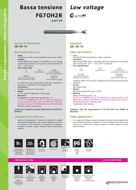
COMANDO E SEGNALAMENTO <strong>FG7OH2R</strong> CONTROL AND SIGNALLING<br />
numero<br />
conduttori<br />
number<br />
of cores<br />
(n)<br />
diametro<br />
indicativo<br />
conduttore<br />
approximate<br />
diameter,<br />
conductor of<br />
the phase core<br />
diameter<br />
(mm)<br />
spessore<br />
medio<br />
isolante<br />
average<br />
insulation<br />
thickness<br />
(mm)<br />
diametro<br />
esterno<br />
massimo<br />
maximum<br />
outer<br />
diameter<br />
(mm)<br />
peso<br />
indicativo<br />
del cavo<br />
approximate<br />
weight<br />
(kg/km)<br />
resistenza<br />
massima a<br />
20 °C in c. c.<br />
maximum DC<br />
resistance at<br />
20 °C<br />
(Ω/km)<br />
portata di corrente (A) con temperatura ambiente di<br />
30 °C in 30 °C in<br />
20 °C<br />
aria tubo in aria interrato in tubo<br />
permissible current rating (A)<br />
in open air in duct<br />
in buried duct<br />
at 30 °C at 30 °C<br />
at 20 °C<br />
ρ=1 °C m/w ρ=1,5 °C m/w<br />
raggio<br />
minimo di<br />
curvatura<br />
minimum<br />
bending<br />
radius<br />
(mm)<br />
sezione 1,5 mm 2 tab. CEI-UNEL 35377 1.5 mm 2 cross-section<br />
5 G 1,5 0,7 15,1 280 13,3 16 14 26 23 155<br />
7 G 1,5 0,7 16,1 335 13,3 13 11,5 18,5 16 170<br />
10 G 1,5 0,7 19,7 415 13,4 13 11,5 18,5 16 190<br />
12 G 1,5 0,7 20,1 460 13,4 11 9,5 14,5 12,5 200<br />
16 G 1,5 0,7 22 560 13,4 11 9,5 14,5 12,5 220<br />
19 G 1,5 0,7 23 635 13,4 9 8 13 11,5 220<br />
24 G 1,5 0,7 26,4 720 13,5 9 8 13 11,5 255<br />
sezione 2,5 mm 2 tab. CEI-UNEL 35377 1.5 mm 2 cross-section<br />
7 G 1,9 0,7 17,8 355 7,98 17,5 15,5 24 21 190<br />
10 G 1,9 0,7 21,6 455 8,06 17,5 15,5 24 21 200<br />
12 G 1,9 0,7 22,2 500 8,06 13,5 12 20 17,5 220<br />
16 G 1,9 0,7 24,3 605 8,06 13,5 12 20 17,5 240<br />
19 G 1,9 0,7 25,4 685 8,06 12 10,5 16 14 255<br />
24 G 1,9 0,7 29,3 820 8,1 12 10,5 16 14 290<br />
32<br />
Note: Le portate dei cavi quadripolari e pentapolari sono state calcolate per tre conduttori attivi. Le portate dei cavi interrati sono state calcolate considerando una<br />
profondità di posa di 0,8 m.<br />
Current carrying capacities for cables consisting of 4/5 conductors are calculated assuming three working conductors. Current carrying capacities for buried cables are<br />
calculated assuming a laying depth of 0.8 m.