Installation Manual CB 27 U CB 27 U Black - Sirio
Installation Manual CB 27 U CB 27 U Black - Sirio
Installation Manual CB 27 U CB 27 U Black - Sirio

You also want an ePaper? Increase the reach of your titles
YUMPU automatically turns print PDFs into web optimized ePapers that Google loves.
INSTALLATION AND TUNING INSTRUCTIONS<br />
INSTALLATION<br />
1) Hole mount installation<br />
A) Hole Drilling: Chose the position on your<br />
vehicle (centre roof is recommended) and drill<br />
a hole according to the mount diameter.<br />
Please ensure a good electrical ground contact<br />
is made.<br />
B) Connections: Position the cable in your<br />
vehicle shortening its length according to your<br />
needs. Connect the PL259-male to the cable<br />
ready for the connection to the transceiver.<br />
C) Electrical Tests: Ensure there is no short<br />
circuit between the central pin and the nut of<br />
the connector. Ensure there is electrical<br />
continuity of the cable from the central pin<br />
(connector side) to the central contact<br />
(antenna side). Ensure there is electrical<br />
continuity of the cable from the nut<br />
(connector side) to the ground (antenna side)<br />
REMARKS: As some antennas are in short<br />
circuit and it would be impossible to do the<br />
test after the installation, we recommend you<br />
test the cable prior to connecting the antenna.<br />
D) <strong>Installation</strong>: Pay attention to securing all<br />
screws and nuts during the final installation.<br />
E) Suggestion: After the final installation and<br />
BEFORE connecting your transceiver, we<br />
recommend an electrical continuity check<br />
between the nut of the PL259 and the ground<br />
of your vehicle.<br />
2) Special mounts installation: Follow the<br />
same instructions of Point 1.<br />
3) Magnetic mount installation: Follow<br />
the instructions supplied with the magnetic<br />
mount.<br />
TUNING<br />
Most of the antennas are factory tuned and<br />
don’t need any extra tuning, but in case of<br />
fine adjustments we recommend to follow the<br />
procedure below:<br />
A) To perform a correct test, move to an open<br />
space far from metal parts such as metal doors,<br />
buildings, towers, gates etc. at minimum 50<br />
metres or more.<br />
B) Connect your SWR-meter between the<br />
antenna connector and your <strong>CB</strong> transceiver<br />
(follow the instructions of your SWR-meter for<br />
the correct use to your equipment).<br />
C) The following procedure is used for the<br />
tuning of the 40 channels <strong>CB</strong>-band Radio in<br />
the range of:<br />
CH-1 = 26.965 MHz to CH-40 = <strong>27</strong>.405<br />
MHz with CH-19 = <strong>27</strong>.185 MHz as centre<br />
band for EU Frequencies.<br />
CH-1 = <strong>27</strong>.601 MHz to CH-40 = <strong>27</strong>.991<br />
MHz with CH-19 = <strong>27</strong>.781 MHz as centre<br />
band for UK Frequencies.<br />
Select CH-1 on your <strong>CB</strong>-transceiver and take<br />
an SWR measurement, writing down the<br />
results. Transmit only for a few seconds<br />
because in case the SWR is too high the<br />
transceiver could be damaged.<br />
D) Repeat the procedure for CH-19 and CH-<br />
40<br />
E) If all SWR results are very high (more than 3)<br />
probably there’s a short circuit in the cable or<br />
your antenna is defective. To avoid<br />
damages to your <strong>CB</strong> transceiver DO<br />
NOT use it until the problem is rectified.<br />
F) If the SWR results are the same on CH-1<br />
and CH-40 and the lower value is on CH-19,<br />
your antenna doesn’t need any tuning.<br />
G) If the SWR result on CH-1 is lower than CH-<br />
40 your antenna is electrically TOO LONG and<br />
you should slightly cut the radiator by 10mm<br />
at a time. Avoid cutting too much. As long as<br />
you get the same values on CH-1 as well as<br />
CH-40.<br />
H) If the SWR result on CH-40 is lower than<br />
CH-1 your antenna is electrically TOO SHORT<br />
and you need to pull out the radiator as long<br />
as you get the same values on CH-1 as well as<br />
CH-40.<br />
Some antennas can be tuned only by<br />
adjusting special rings, nuts or screws so you<br />
can follow the above procedure but you don’t<br />
need to cut or extend the radiator.<br />
B Copyright SIRIO antenne - Technical Data are subjected to change - Printed in ITALY - Rev. 13/11/2007 - Cod. ID007<br />
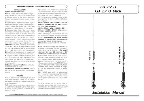
<strong>CB</strong> <strong>27</strong> U<br />
<strong>CB</strong> <strong>27</strong> U<br />
<strong>CB</strong> <strong>27</strong> U <strong>Black</strong><br />
<strong>CB</strong> <strong>27</strong> U BLACK<br />
<strong>Installation</strong> <strong>Manual</strong>
DESCRIPTION<br />
ISTRUZIONI DI INSTALLAZIONE E TARATURA<br />
1/4 λ vehicular antenna conceived for car-roof installation. It is base loaded and its<br />
whip, made of chromed or black chromed stainless steel, can be tilted for 180 o . With<br />
carefull tuning, 80 channel can be covered.<br />
SPECIFICATIONS<br />
Type : base loaded<br />
Impedance : 50 Ω<br />
Frequency range : <strong>27</strong> - 28.5 MHz<br />
Polarization : Vertical<br />
SWR @ res. freq. : ≤ 1.2<br />
Max. power : 15 Watt(CW) continuous,<br />
: 150 Watts (CW) short time<br />
Bandwidth @ SWR 2 : ≥ 1400 KHz<br />
Cable : 4m RG 58<br />
Height (approx.) : 790 mm<br />
Weight (approx.) : 450 gr<br />
Standard mount : "N"<br />
Mounting hole : Ø 12.5 mm<br />
STANDARD MOUNT<br />
Mounting hole: Ø12.5mm<br />
Overall size: Ø 41mm<br />
N chrome 2500102.01<br />
N black 2500102.02<br />
ID007<br />
ALTERNATIVE MOUNTS<br />
NE chrome 2500202.01<br />
NE black 2500202.02<br />
NP chrome 2500302.01<br />
NP black 2500302.02<br />
HI-QUALITY ANTENNAS MADE IN ITALY<br />
ALTERNATIVE MAGNETIC<br />
MOUNTS<br />
MAG H 12 S chrome 2502502.01<br />
MAG H 12 S black 2502502.02<br />
MAG 125 S chrome 2502602.01<br />
MAG 125 S black 2502602.02<br />
INSTALLAZIONE<br />
1) Installazione con foratura della carrozzeria:<br />
A) Foratura: Praticare il foro del diametro richiesto<br />
nella posizione desiderata (consigliato<br />
a centro tetto). Togliere la vernice nella parte<br />
interna della carrozzeria per garantire un buon<br />
contatto elettrico di massa.<br />
B) Collegamenti: Posizionare il cavo dell’antenna<br />
accorciandolo in base alle necessità, quindi<br />
montare il connettore PL 259 maschio per<br />
la connessione all’apparato <strong>CB</strong>.<br />
C) Verifiche elettriche: Assenza di corto circuito<br />
tra spina centrale e ghiera di massa del connettore,<br />
continuità elettrica del conduttore<br />
centrale da un’estremità all’altra del cavo, continuità<br />
elettrica calza cavo dalla ghiera lato connettore<br />
al contatto di massa lato connettore<br />
d’antenna.<br />
N.B.: Si consiglia di testare il cavo lasciandolo<br />
scollegato dall’antenna poiché alcune antenne<br />
sono elettricamente in corto circuito e non<br />
è possibile eseguire il test ad installazione completata.<br />
D) Installazione: Completare il montaggio dell’antenna<br />
serrando adeguatamente viti e bulloni.<br />
E) Consiglio: a montaggio terminato e PRIMA<br />
di connettere il trasmettitore, si consiglia di<br />
verificare la continuità elettrica tra la ghiera del<br />
connettore PL 259 e un punto di massa della<br />
carrozzeria.<br />
2) Installazione con attacchi speciali: seguire<br />
la stessa procedura del punto 1.<br />
3) Installazione temporanea con basi<br />
magnetiche: seguire le istruzioni fornite con<br />
la base magnetica ricordandosi che si tratta di<br />
un’installazione TEMPORANEA.<br />
TARATURA<br />
Le antenne sono pre-tarate in fabbrica pertanto<br />
nella maggior parte dei casi non necessitano<br />
di taratura. In caso si renda necessaria<br />
una leggera taratura consigliamo di seguire la<br />
procedura riportata di seguito.<br />
A) Recarsi in spazio aperto ad almeno 50 metri<br />
o più da oggetti metallici quali cancelli, lampioni,<br />
edifici o tralicci.<br />
B) Collegare un SWR-meter (ROS-metro) tra il<br />
connettore dell’antenna e il trasmettitore <strong>CB</strong>.<br />
Seguire le istruzioni del ROS-metro per il corretto<br />
utilizzo dell’apparato.<br />
C) La seguente procedura si applica per la<br />
taratura dei 40 canali omologati per banda<br />
<strong>CB</strong> compresi nel range di frequenza da CH-1<br />
= 26.965 MHz a CH-40 = <strong>27</strong>.405 MHz<br />
con CH-19 =<strong>27</strong>.185MHz in centro banda.<br />
Selezionare il CH-1 sul trasmettitore <strong>CB</strong> ed effettuare<br />
la misura di SWR annotandone il valore.<br />
Trasmettere sempre per pochi secondi<br />
perché se l’ SWR fosse molto alto si<br />
potrebbe danneggiare il trasmettitore.<br />
D) Ripetere l’operazione anche per il CH-19 e<br />
il CH-40.<br />
E) Se tutti e tre i valori di SWR sono molto alti<br />
(maggiori del valore 3) o tendenti a infinito,<br />
probabilmente è presente un corto circuito<br />
nel cablaggio oppure l’antenna è guasta. Per<br />
evitare di danneggiare il vostro trasmettitore<br />
<strong>CB</strong> NON utilizzarlo finché il problema<br />
non sarà risolto.<br />
F) Se i valori di SWR sono uguali per CH-1 e<br />
CH-40 e il valore minimo si ha su CH-19, la<br />
vostra antenna non necessita di alcuna<br />
taratura.<br />
G) Se il valore di SWR è più basso su CH-1<br />
rispetto a CH-40, la vostra antenna é elettricamente<br />
“lunga”, quindi accorciare lo stilo di<br />
circa 10mm alla volta fino ad ottenere gli stessi<br />
valori di SWR sia su CH-1 che su CH-40.<br />
H) Se il valore di SWR è più basso su CH-40<br />
rispetto a CH-1, la vostra antenna é elettricamente<br />
“corta”, quindi allungare lo stilo sfilandolo<br />
di 10mm alla volta fino ad ottenere gli<br />
stessi valori di SWR sia su CH-1 che su CH-40.<br />
Per alcuni tipi di antenna la modifica della frequenza<br />
si ottiene agendo su speciali Anelli,<br />
Viti o Ghiere di taratura, pertanto la procedura<br />
sopra descritta rimane inalterata ma non<br />
occorrerà accorciare o allungare lo stilo.