MI Navigationssystem 5400-5500 Mazda 3- D-GB- F- I-E.qxd - jewuwa
MI Navigationssystem 5400-5500 Mazda 3- D-GB- F- I-E.qxd - jewuwa
MI Navigationssystem 5400-5500 Mazda 3- D-GB- F- I-E.qxd - jewuwa

Create successful ePaper yourself
Turn your PDF publications into a flip-book with our unique Google optimized e-Paper software.
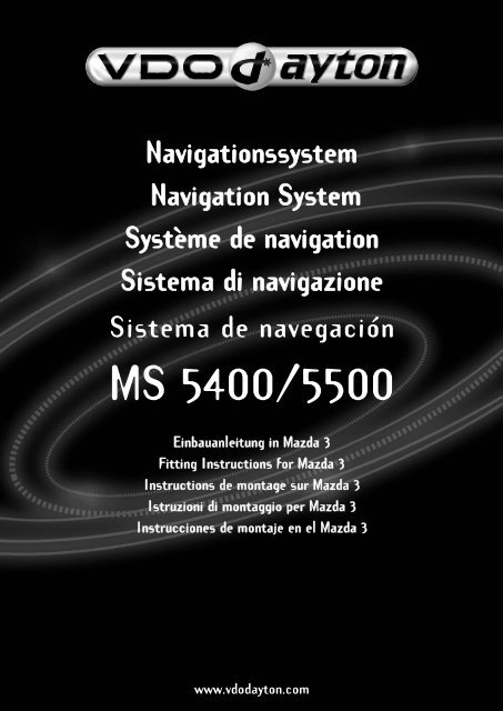
<strong>Navigationssystem</strong><br />
Navigation System<br />
Système de navigation<br />
Sistema di navigazione<br />
Sistema de navegación<br />
MS <strong>5400</strong>/<strong>5500</strong><br />
Einbauanleitung in <strong>Mazda</strong> 3<br />
Fitting Instructions for <strong>Mazda</strong> 3<br />
Instructions de montage sur <strong>Mazda</strong> 3<br />
Istruzioni di montaggio per <strong>Mazda</strong> 3<br />
Instrucciones de montaje en el <strong>Mazda</strong> 3<br />
www.vdodayton.com
VDO Dayton MS <strong>5400</strong>/<strong>5500</strong> – <strong>Mazda</strong> 3 D <strong>GB</strong> F I E<br />
1. Vorarbeiten / Preparations / Préparation / Preparazione / Trabajos previos<br />
Auszubauende Teile:<br />
Batterie abklemmen / Fußraumverkleidung (vorne /<br />
rechts) / Einstiegsleiste (vorne / rechts) / Zierleiste<br />
über Handschuhfach und Radio / Handschuhfach /<br />
mittlere Armaturenbrettabdeckung / Radio / Verkleidung<br />
Kombiinstrument / Beifahrersitz.<br />
Parts to be removed:<br />
Disconnect battery / lining in leg space (front righthand<br />
side) / entrance strip (front r.h. side) / trimming<br />
above glove compartment and radio / glove compartment<br />
/ central instrument-panel cover / radio /<br />
instrument-cluster panelling / passenger seat.<br />
Pièces à démonter :<br />
Débrancher la batterie / tapis de sol (devant / à droite)<br />
/ barre de montée (devant / à droite) / moulure décorative<br />
au-dessus de la boîte à gants et de la radio / boîte à gants / revêtement médian de la planche de bord / radio /<br />
revêtement de l’instrument de bord combiné / siège passager.<br />
Parti da smontare:<br />
Staccare la batteria / rivestimento vano piedi (anteriore / destro) / coprisoglia (anteriore / destro) / listello decorativo<br />
sopra il vano portaguanti e la radio / vano portaguanti / rivestimento centrale del cruscotto / radio / rivestimento<br />
strumentazione combinata / sedile passeggero.<br />
Elementos a desmontar:<br />
Desembornar la batería / revestimiento del espacio para los pies (delante / derecha) / listón de entrada (delante / derecha)<br />
/ embellecedor por encima de la guantera y la radio / guantera / cubierta central del tablero de instrumentos /<br />
radio / revestimiento instrumento combinado / asiento del acompañante<br />
2. Montage Monitoraufnahme / Fitting monitor bracket / Montage du logement de moniteur /<br />
Montaggio supporto monitor / Montaje alojamiento del monitor<br />
Mittlere Armaturenbrettabdeckung bearbeiten.<br />
Bohrungen und Ausschnitt entsprechend der<br />
Perforierung auf der Rückseite ausführen. Ablagefach<br />
(B33A-V6-535F) entsprechend der beiliegenden<br />
Montageanleitung in Ausschnitt montieren.<br />
Prepare central instrument-panel cover.<br />
Make holes and cut-out according to perforation on<br />
rear side. Fit shelf (B33A-V6-535F) into cut-out<br />
according to enclosed instructions.<br />
Travailler sur le revêtement médian de la planche<br />
de bord.<br />
Réaliser les perçages et les découpes conformément<br />
à la perforation au dos. Monter dans la découpe le<br />
compartiment d’insertion (B33A-V6-535F)<br />
conformément aux instructions de montage ci-jointe.<br />
Preparare il rivestimento centrale del cruscotto. Eseguire i fori e i ritagli in base alla perforazione sul lato posteriore.<br />
Montare il vano portaoggetti (B33A-V6-535F) nel ritaglio, conformemente alle istruzioni di montaggio allegate.<br />
Tratar la cubierta central del tablero de instrumentos. Ejecutar los taladros y la escotadura según la perforación en<br />
el dorso. Montar el compartimento (B33A-V6-535F) en la escotadura según las instrucciones de montaje adjuntas.<br />
TU00-0727-5607150 0404 2
VDO Dayton MS <strong>5400</strong>/<strong>5500</strong> – <strong>Mazda</strong> 3 D <strong>GB</strong> F I E<br />
3. Montage Monitoraufnahme / Fitting monitor bracket / Montage du logement de moniteur /<br />
Montaggio supporto monitor / Montaje alojamiento del monitor<br />
Lochbild für Kabeldurchführung des Monitors, von der<br />
linken auf die rechte Seite übertragen und<br />
ausschneiden. 6,5mm Bohrung (40mm von<br />
Oberkante) zur Monitorbefestigung in der Mitte des<br />
Ablagefaches ausführen.<br />
Transfer hole pattern for monitor cable bushing from<br />
the left to the right-hand side and cut out. Drill hole<br />
Ø 6.5 mm (40 mm from the top edge) for monitor<br />
attachment in centre of the shelf compartment.<br />
Reporter du côté gauche au côté droit le gabarit de<br />
perçage pour le passage des câbles du moniteur, puis<br />
découper. Effectuer un perçage de Ø 6,5 mm (40 mm<br />
à partir de l’arête supérieure) pour la fixation du<br />
moniteur au centre du compartiment d’insertion<br />
. Riportare lo schema di foratura per il passaggio dei<br />
cavi del monitor dal lato sinistro a quello destro e<br />
eseguire i ritagli.<br />
Eseguire un foro di Ø 6,5 mm al centro del vano portaoggetti (a 40 mm dal bordo superiore) per fissare il monitor.<br />
Transferir el esquema de taladros para el paso de los cables del monitor del lado izquierdo al derecho y recortar.<br />
Ejecutar un taladro de Ø 6,5 mm (a 40 mm del borde superior) para la fijación del monitor en el centro del<br />
compartimento.<br />
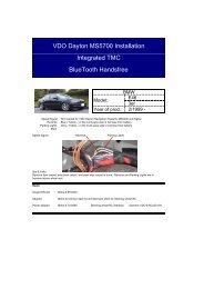
4. Montage Monitor / Monitor installation / Montage du moniteur / Montaggio del monitor /<br />
Montaje del monitor<br />
Monitorkabel durch ausgeführte Öffnung führen und<br />
mit Monitor verbinden. Monitor mit beiliegenden<br />
Schrauben und Schiene auf Monitoraufnahme<br />
montieren.<br />
ACHTUNG: Monitoraufnahme 3600-78-313H (Universalhalter)<br />
nicht im Lieferumfang! Muss als Zubehör<br />
über Zentrallager bestellt werden.<br />
Push the monitor cable through the drilled opening<br />
and connect it to the monitor. Attach the monitor to the<br />
monitor bracket with the screws and strip provided.<br />
????????????<br />
????????<br />
????????<br />
Faire passer le câble du moniteur par l’orifice percé et<br />
le raccorder au moniteur. Monter le moniteur dans son<br />
logement avec les vis et le rail fournis.<br />
????????????<br />
????????<br />
????????<br />
Far passare il cavo del monitor attraverso il foro praticato e collegarlo al monitor. Montare il monitor con le viti e la guida<br />
in dotazione sul supporto.<br />
????????????<br />
????????<br />
Pasar el cable del monitor por el orificio taladrado y conectarlo con el monitor. Montar el monitor con los tornillos<br />
adjuntos y el riel en el alojamiento del monitor.<br />
????????????<br />
????????<br />
TU00-0727-5607150 0404 3
VDO Dayton MS <strong>5400</strong>/<strong>5500</strong> – <strong>Mazda</strong> 3 D <strong>GB</strong> F I E<br />
5. Einbau der GPS-Antenne / Fitting of the GPS-Antenna / Montage de l'antenne GPS /<br />
Montaggio dell'antenna GPS / Montaje de la antena GPS<br />
Die GPS-Antenne wird unterhalb des Ablagefaches<br />
auf die Strebe in der Mitte des Armaturenbrettes<br />
geklebt. Das Anschlusskabel wird von dort durch den<br />
rechten Fußraum zur Position des Rechners verlegt.<br />
The GPS antenna is bonded to the brace at the centre<br />
of the instrument panel beneath the shelf compartment<br />
with adhesive. From there, the connecting cable<br />
is laid through the right-hand leg space to the processor<br />
position.<br />
L’antenne GPS est collée en dessous du compartiment<br />
d’insertion sur l’entretoise située au milieu de la planche<br />
de bord. Le câble de raccord est posé à partir de là en<br />
passant par l’espace pieds de droite vers l’emplacement<br />
du module.<br />
L’antenna GPS viene incollata al di sotto del vanno portaoggetti sulla traversa al centro del cruscotto. Il cavo di<br />
collegamento viene quindi fatto passare attraverso il vano piedi destro fino al punto in cui è collocato il calcolatore.<br />
La antena GPS se pega por debajo del compartimento en el puente en el centro del tablero de instrumentos. El cable<br />
de conexión se tiende desde allí a través del espacio para los pies a la derecha hasta la posición del ordenador.<br />
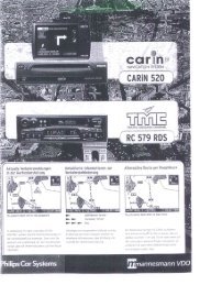
6. Rechner-Einbau / Processor installation / Installation du module<br />
Montaggio del calcolatore / Montaje del ordenador<br />
Den Rechner unter dem Beifahrersitz montieren. b) Optional mit Einbaurahmen MA 2400/00<br />
a) Nur mit beiliegenden Haltern. (muss separat bestellt werden).<br />
Mount the processor underneath the passenger seat. b) Optional with installation frame MA 2400/00<br />
a) Only with attached brackets. (has to be ordered separately).<br />
Monter le module sous le siège passager. b) En option avec le cadre MA 2400/00<br />
a) Uniquement avec les pattes fournies. (à commander séparément).<br />
Montare il calcolatore sotto il sedile del passeggero b) In alternativa con il supporto di montaggio<br />
a) Solo con gli attacchi in dotazione. MA 2400/00 (da ordinate separatamente).<br />
Montar el ordenador debajo del asiento del acompañante. b) Opcionalmente, montaje con el marco de montaje<br />
a) Utilizar únicamente los soportes adjuntos. MA 2400/00 (se tiene que pedir por separado).<br />
TU00-0727-5607150 0404 4
VDO Dayton MS <strong>5400</strong>/<strong>5500</strong> – <strong>Mazda</strong> 3 D <strong>GB</strong> F I E<br />
7. Rechner-Einbau / Processor installation / Installation du module<br />
Montaggio del calcolatore / Montaje del ordenador<br />
Klettverschluß an Haltern befestigen und den Rechner<br />
laut Abbildung am Boden fixieren und mit den Kabeln<br />
verbinden. Kabelverlegung unter dem Teppich, entlang<br />
des rechten Schwellers.<br />
Optional: Einbaurahmen befestigen, Kabel durch den<br />
Einbaurahmen legen und dann am Rechner<br />
kontaktieren und den Rechner in den Rahmen<br />
schieben.<br />
Attach the hook-and-loop tape to the holders and fix<br />
the processor to the floor as shown in the diagram,<br />
and connect with the cables. Lay the cable under the<br />
carpet along the right-hand sillboard.<br />
Optional: Attach the fitting frame, lay the cable through<br />
fitting frame, connect it to the processor and push the<br />
processor into the frame.<br />
Fixer la fermeture auto-agrippante aux pattes et fixer<br />
le module sur le plancher, conf. à la figure, puis<br />
brancher les câbles. Pose des câbles sous le tapis le<br />
long du bas de marche droit.<br />
En option : fixer le cadre de montage, faire passer les<br />
câbles à travers le cadre puis les raccorder au<br />
module, enfin pousser le module dans le cadre.<br />
Attaccare la chiusura in velcro ai supporti fissando il<br />
calcolatore sul pavimento come mostrato nella figura<br />
e collegarlo quindi ai cavi. I cavi vanno fatti passare<br />
sotto la moquette, lungo la soglia destra.<br />
In alternativa: Fissare il supporto di montaggio, far<br />
passare il cavo attraverso il supporto collegandolo al<br />
calcolatore e spingere quindi il calcolatore nel<br />
supporto.<br />
Fijar el cierre de velcro en los soportes, sujetar el<br />
ordenador en el suelo según indica la figura y<br />
conectarlo con los cables. Tender el cable debajo de<br />
la moqueta, a lo largo del apoyapié derecho.<br />
Opcionalmente: Fijar el marco de montaje, pasar el<br />
cable por el marco de montaje, conectarlo al<br />
ordenador e introducir el ordenador en el marco.<br />
TU00-0727-5607150 0404 5
VDO Dayton MS <strong>5400</strong>/<strong>5500</strong> – <strong>Mazda</strong> 3 D <strong>GB</strong> F I E<br />
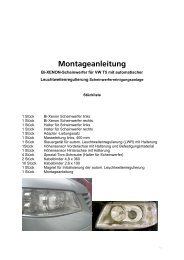
8. Bedienteil-Montage (Fernbedienung) / Control installation (Remote control)<br />
Installation de la commande (télécommande) / Montaggio del comando (telecomando)<br />
Montaje de la unidad de operación (mando a distancia)<br />
Die Lenkradfernbedienung wird am Lenkrad mit dem<br />
dafür vorgesehenen Band gemäß Abbildung befestigt.<br />
The steering-wheel remote control is fixed to the<br />
steering wheel with the tape provided as shown in the<br />
diagram.<br />
La télécommande est fixée au volant avec le bracelet<br />
prévu à cet effet, cf. à la figure.<br />
Il telecomando da volante viene fissato al volante con<br />
l'apposito nastro, come mostrato nella figura.<br />
El mando a distancia del volante se fija en el volante<br />
mediante la cinta prevista al efecto, según indica la<br />
figura.<br />
TU00-0727-5607150 0404 6
VDO Dayton MS <strong>5400</strong>/<strong>5500</strong> – <strong>Mazda</strong> 3 D <strong>GB</strong> F I E<br />
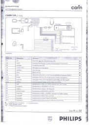
9. Kabelanschlüsse / Cable connections / Branchements du câble<br />
Collegamento de cavo / Conexiones de cable<br />
Kabel wie folgt anschließen:<br />
Connect cable as described below:<br />
Brancher le câble comme décrit ci-dessous:<br />
braun (Kl. 31)<br />
rot (Kl. 30)<br />
violett (Kl. 15)<br />
grau<br />
Tachosignal<br />
= Masse: am Original Massepunkt an<br />
der rechten A-Säule unter der Handschuhfachverkleidung.<br />
= Dauerplus: am weißen Radiostecker.<br />
Kabelfarbe: orange-schwarz.<br />
= Zündungsplus: am Kombiinstrument<br />
am linken Stecker Pin 22. Kabel<br />
grün-schwarz (ca. 1,5 mm 2 ).<br />
= Beleuchtung: am weißen Radiostecker.<br />
Kabelfarbe: Orange<br />
= Am Kombiinstrument rechter weißer<br />
Stecker. Kabelfarbe: weiß-schwarz.<br />
brown (term.31)<br />
red (term. 30)<br />
violet (term. 15)<br />
grey<br />
Speed signal<br />
= Earth: to the original earth point on<br />
the right-hand A-column under the<br />
glove-compartment lining.<br />
= Continuous plus: to white radio plug.<br />
Wire colour: orange-black<br />
= Ignition positive: to instrument<br />
cluster, left-hand plug pin 22.<br />
Wire green-black (approx. 1.5 mm 2 ).<br />
= Lighting: to white radio plug.<br />
Wire colour: orange<br />
= To instrument cluster, right-hand<br />
white plug.<br />
Wire colour: black-white.<br />
marron (broche 31) = Masse : sur le point de masse<br />
d’origine sur le montant A de droite,<br />
sous le revêtement de la boîte à<br />
gants.<br />
rouge (broche 30) = Plus permanent : au connecteur<br />
radio blanc.<br />
Couleur de fil : orange-noir.<br />
violet (broche 15) = Allumage Plus : sur l’instrument de<br />
bord combiné, au connecteur de<br />
gauche, broche 22.<br />
Fil vert-noir (env. 1,5 mm 2 ).<br />
gris<br />
= Éclairage : au connecteur radio<br />
blanc.<br />
Couleur de fil : orange.<br />
Signal vitesse = Sur l’instrument de bord combiné,<br />
connecteur blanc de droite.<br />
Couleur de fil : blanc-noir.<br />
TU00-0727-5607150 0404 7
VDO Dayton MS <strong>5400</strong>/<strong>5500</strong> – <strong>Mazda</strong> 3 D <strong>GB</strong> F I E<br />
9. Kabelanschlüsse / Cable connections / Branchements du câble<br />
Collegamento de cavo / Conexiones de cable<br />
Collegare le cavo come segue:<br />
Conectar el cable como sigue:<br />
marrone (mors. 31) = massa: nel punto originale di massa sulla pilastro A sotto il rivestimento del vano portaguanti.<br />
rosso (mors. 30) = positivo permanente: al connettore bianco della radio. Colore cavo: arancio-nero.<br />
viola (mors. 15) = positivo d’accensione: sulla strumentazione combinata al connettore sinistro spillo 22.<br />
Cavo verde-nero (ca. 1,5 mm 2 ).<br />
grigio<br />
= illuminazione: al connettore bianco della radio.<br />
Colore cavo: arancio<br />
Segnale tachimetro = sulla strumentazione combinata connettore destro bianco.<br />
Colore cavo: bianco-nero<br />
marrón (borne 31) = Masa: en el punto de masa original en la columna A derecha, debajo del revestimiento de la guantera.<br />
rojo (borne 30) = Positivo permanente: en el conector blanco de la radio. Color del cable: naranja.negro.<br />
violeta (borne 15) = Positivo de encendido: en el instrumento combinado en el conector izquierdo pin 22.<br />
Cable verde-negro (aprox. 1,5 mm 2 )<br />
gris<br />
= Iluminación: en el conector blanco de la radio.<br />
Color del cable: naranja<br />
Señal de tacómetro = En el instrumento combinado, conector blanco derecho.<br />
Color del cable: blanco-negro<br />
10. Monitor-Endmontage / Final monitor installation / Montage final du moniteur /<br />
Montaggio finale del monitor / Montaje final del monitor<br />
Armaturenbrett-Abdeckung mit vormontiertem Monitor<br />
wieder einsetzen und Monitorkabel zusammen mit<br />
restlichen Kabeln auf der rechten Seite zum Rechner<br />
verlegen.<br />
Replace instrument-panel cover with monitor premounted<br />
and lay monitor cable to the processor along with<br />
other cables on the right-hand side.<br />
Remettre en place le revêtement de la planche de bord<br />
avec moniteur prémonté et poser le câble du moniteur et<br />
les autres câbles du côté droit en direction du module.<br />
Inserire nuovamente il rivestimento del cruscotto con il<br />
monitor premontato e far passare il cavo del monitor assieme<br />
agli altri cavi sul lato destro verso il calcolatore.<br />
Volver a insertar la cubierta del tablero de instrumentos<br />
con el monitor premontado y tender el cable del monitor<br />
junto con los demás cables en el lado derecho<br />
hasta el ordenador.<br />
TU00-0727-5607150 0404 8
VDO Dayton MS <strong>5400</strong>/<strong>5500</strong> – <strong>Mazda</strong> 3 D <strong>GB</strong> F I E<br />
11. Abschliessende Arbeiten / Finishing work / Derniers travaux /<br />
Lavori conclusivi / Trabajos finales<br />
- Achten Sie darauf, daß der Kabelbaum an der richtigen Stelle verläuft und ordnungsgemäß befestigt ist.<br />
- Zur Vermeidung von Beschädigungen an der Kabelisolation ist Berührung mit scharfen Kanten zu vermeiden.<br />
- Teile gemäß Abbildung montieren.<br />
- Paneele wieder anbringen, achten Sie darauf, dass der Kabelbaum ordnungsgemäß und genau positioniert ist.<br />
- Batterie wieder anschliessen und alle Funktionen pruefen.<br />
- Ensure that the cable harness is laid in the correct position and properly fixed.<br />
- To avoid damaging the cable insulation, avoid all contact with sharp edges.<br />
- Fit all parts according to diagram.<br />
- Replace panels. Ensure that the cable harness is positioned correctly and accurately.<br />
- Re-connect the battery and check all funcitions.<br />
- Veiller à ce que le faisceau de câbles passe au bon endroit et soit correctement fixé.<br />
- Pour éviter des dommages sur l’isolation des câbles, éviter le contact avec des arêtes coupantes.<br />
- Monter les pièces conf. à la figure.<br />
- Remettre en place les panneaux, veiller à ce que le faisceau de câbles soit positionné correctement et avec précision.<br />
- Rebrancher la batterie et contrôler toutes les fonctions.<br />
- Controllare che il fascio di cavi passi nel punto esatto e che sia fissato correttamente.<br />
- Per evitare danni all’isolamento dei cavi occorre evitare il contatto con spigoli taglianti.<br />
- Montare le parti conformemente alla figura.<br />
- Fissare nuovamente i pannelli, facendo attenzione che il fascio di cavi sia posizionato in modo corretto e preciso.<br />
- Collegare nuovamente la batteria e controllare tutte le funzioni.<br />
- Preste atención a que el mazo de cables transcurra por el lugar correcto y esté fijado adecuadamente.<br />
- Para evitar daños en el aislamiento de los cables, se tiene que evitar su contacto con bordes afilados.<br />
- Montar los elementos según la figura.<br />
- Volver a montar los paneles, prestando atención al posicionamiento correcto y exacto del mazo de cables.<br />
- Volver a conectar la batería y comprobar todas las funciones.<br />
TU00-0727-5607150 0404 9