EINBAUANLEITUNG
EINBAUANLEITUNG
EINBAUANLEITUNG

Create successful ePaper yourself
Turn your PDF publications into a flip-book with our unique Google optimized e-Paper software.
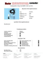
<strong>EINBAUANLEITUNG</strong><br />
VW<br />
Sciricco Bj. 09.08-<br />
22-50<br />
18-19<br />
16-17<br />
KIT 423413 13-pin<br />
D !<br />
GB !<br />
I ! F !<br />
Der Einbau des Elektrosatzes muss von einer<br />
Fachwerkstatt oder einer entsprechend<br />
qualifizierten Person durchgeführt werden.<br />
Vor Beginn aller Montagearbeiten unbedingt die<br />
Einbauanleitung komplett durchlesen. Nach<br />
Einbau des Elektrosatzes ist die<br />
Einbauanleitung den Serviceunterlagen des<br />
Fahrzeuges beizulegen.<br />
Bei unsachgemäßer Anwendung oder<br />
Veränderung des Elektrosatzes bzw. der darin<br />
befindlichen Bauteile erlischt jeder Anspruch auf<br />
Gewährleistung. Beim fahren ohne Anhänger<br />
oder Lastenträger müssen ggf. verwendete<br />
Adapter immer aus der Steckdose entfernt<br />
werden. Änderungen bezüglich Konstruktion,<br />
Ausstattung, Farbe sowie Irrtum vorbehalten. Alle<br />
Angaben und Abbildungen sind unverbindlich.<br />
Intallation of the towing electrics kit must be<br />
undertaken by a specialist workshop or an<br />
appropriately qualified person. Befor starting work,<br />
you must read the installation instructions through<br />
completely. After installing the touwing electrics cit,<br />
the installation instructions should be kept with the<br />
vehicle service documentation.<br />
All claims under the guarantee will lapse in case of<br />
thetowing electrics kit or any of its component parts.<br />
When driving without a trailer or load carrier, any<br />
adapter installed must be removed from the<br />
electrical socket. We reverse the right to alter the<br />
design, content or colour. We accept no liability for<br />
any errors in these instructions. All details and<br />
illustrations are non-binding.<br />
L`installazionedel kit elettrico deve essere<br />
effettuata da un`officina o dapersonale<br />
specializzato. Prima di iniziare tutti i lavori di<br />
montaggio, leggere da cima a fondo le istruzioni.<br />
Dopo aver installato il kit elettrico si prega di<br />
allegare le instruzioni di montaggio ai documenti di<br />
manutenzione del veicolo!<br />
In caso die uso improprio di modifiche del kit<br />
elettrico e delle componenti del medesimo, ogni<br />
diritto di garanzia decade. Durante la guida senza<br />
rimorchio o portacarichi, togliere sempre gli<br />
adattatori dalla presa di corrente. Con riserva<br />
di modifiche relative a costruzione,<br />
equipaggiamento, colore e salvo errori. Tuttele<br />
indicazioni e illustrazioni non sono vincolanti.<br />
Le montage du kit de conexion élecrtique doit être<br />
effectué par un atelier spécialisé ou par une<br />
personne qualifiée en la matière. Avant le début<br />
des travaux, liere impérativement les instructions<br />
de montage dans leur intégralité. Après le<br />
montage du kit de connexion électrique, joindre<br />
les instructions de montage aux documents du<br />
véhicule.<br />
Un usage inapproprié ou des modifications du kit<br />
de connexion électrique, ou des pièces qui le<br />
composent, enrtraînent l'expiration de tout droit à<br />
la garantie. Lors d'une conduite sans remorque ou<br />
porteur de charge, les adaptateurs utilisés doivent,<br />
le cas échéant, toujours être enlevés de la prise<br />
de courant. Sous réservede modifications de<br />
constructions, équipement couleurs ou erreur.<br />
Données et illustrations sous toute réserve.<br />
Bei Anhängern ohne Nebelschlussleuchte sollte<br />
diese nachgerüstet werden.<br />
In case of missing a rear fog lamp on the trailer, it<br />
should be retrofitted.<br />
In caso di rimorchi non corredati di luce<br />
retronebbia, questa dovrebbe essere istallata.<br />
Pour les remorques qui sont pas équipés avec<br />
feux anti-brouillard arrière, il devrait être installé.<br />
Für technische bzw. elektronische Änderungen,<br />
welche nach erstmaliger Inbetriebnahme des<br />
Elektrosatzes vom Fahrzeughersteller<br />
durchgeführt werden und beispielsweise zu<br />
Fehlfunktionen der Anhängersteckdose oder<br />
deren Peripherie führen, übernehmen wir<br />
keinerlei Gewährleistung!<br />
We accept no responsibility and give no guarantee<br />
for technical and electrical modifications made after<br />
the initial operation of the towing electrics kit by the<br />
vehicle manufacturer and which may lead, for<br />
example to malfunction of the trailer socket or its<br />
peripheries.<br />
Per le modiche tecniche ed elettroniche eseguite Nous n'assumons aucune reponsabilité ni garantie<br />
dopo la prima messa in funzione del kit elettrico da pour les modifications techniques et électroniques<br />
parte del costruttore del veicolo, e che portano, per ayant été effectuées après la première mise en<br />
esempio, a un malfunzionamento della presa del<br />
rimorchio o della sua pertiferia, non assumiamo<br />
alcuna responsabilità.!<br />
service du kit de connexion électrique par le<br />
constructeur automobile et ayant mené par<br />
exemple à mauvais fonctionnements de la prise<br />
de remorque ou de sa périphérie.<br />
Das Anhängermodul ist nicht diagnosefähig!<br />
Sollten herstellerseitige Diagnoseprozesse bzw.<br />
softwaregestützte Prüfmechanismen<br />
Fehlerprotokolle generieren, welche direkt oder<br />
indirekt mit Anhängerbetrieb in Zusammenhang<br />
stehen, ist das Anhängermodul vom Leitungssatz<br />
für die Anhängersteckdose zu trennen und ein<br />
nochmaliger Diagnosevorgang zu starten!<br />
The trailer module is not diagnostics-capable. If the<br />
manufctturer´s diagnostics processes or softwaresupported<br />
test mechanisms generate error reports<br />
directly or indirectly linked with trailer operation, the<br />
trailer module must be disconnected from the leads<br />
to the trailer socket and a new diagnostic process<br />
initiated.<br />
Il modulo del rimorchio non è idoneo alla diagnosi!<br />
Nel caso in cui processi diagnostici o<br />
apparecchiature di prova controllate da software<br />
dovessero genrare dei protocolli d`errore in<br />
rapporto diretto o indiretto con l`uso del rimorchio,<br />
si deve staccare il modulo delrimorchio dal<br />
conduttore per la presa del rimorchio, e avviare<br />
nuovamente la diagnosi!<br />
Le module remorque ne content pas de fonction<br />
diagnostic! Au cas où de processus de diagnostic<br />
défiis par le fabricant ou des mécanismes de<br />
contrôle assistés par ordinteur devaient générer<br />
des messages d'erreur directement ou indirectement<br />
en rapport avec le fonctionnement de la<br />
remorque, il est impératif pour la prise de<br />
remorque de détacher le module remorque du<br />
gruppe électrique et d'initier une nouvelle procédure<br />
de diagnostic.<br />
10.03.2009-02 / Änderungen vorbehalten Seite 1 von 20
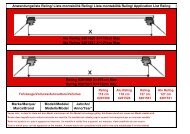
<strong>EINBAUANLEITUNG</strong><br />
KIT 423413<br />
13-pin<br />
17<br />
22-34<br />
-<br />
36-47<br />
48-50 18<br />
19<br />
16<br />
10.03.2009-02 / Änderungen vorbehalten Seite 2 von 20
<strong>EINBAUANLEITUNG</strong><br />
1<br />
2<br />
10.03.2006-02 / Änderungen vorbehalten Seite 3 von 20
<strong>EINBAUANLEITUNG</strong><br />
3<br />
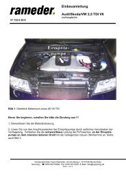
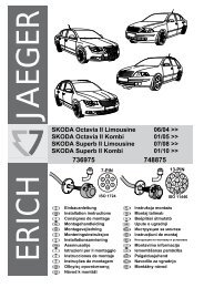
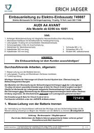
7- + 13-pin 13-pin<br />
1 bk/wh 8 bu/rd<br />
2 gy 9 rd/bu<br />
3 bn 10 ye<br />
4 bk/gn 11 wh/bn<br />
5 gy/rd R 12 no<br />
6 bk/rd STOP 13 wh/bn<br />
7 gy/bk<br />
L<br />
1 3 5<br />
2 4<br />
R<br />
4<br />
D<br />
GB<br />
F<br />
NL<br />
DK<br />
N<br />
S<br />
FIN<br />
I<br />
E<br />
CZ<br />
H<br />
RU<br />
LT<br />
LV<br />
EST<br />
SK<br />
P<br />
wh bk ye bn gy gn rd<br />
bu or pu no<br />
weiss schwarz gelb braun grau grün rot blau orange violett<br />
with black yellow brown grey green red blue orange purple<br />
nicht<br />
belegt<br />
not<br />
occupied<br />
blanc noir jaune brun gris vert rouge bleu orange violet inutilisé<br />
wit zwart geel bruin grijs groen rood blauw oranje violet<br />
hvid sort gul brun grå grøn rød blå orange violet<br />
hvit svart gul brun grå grønn rød blå oransje fiolett ikke i bruk<br />
hvit svart gul brun grå grönn röd blå orange violett ej använd<br />
valkoinen musta keltainen ruseka harmaa vihreä punainen sininen oranssi violetti ei varattu<br />
bianco nero giallo marrone grigio verde rosso blu arancione viola libero<br />
blanco negro amarillo marón gris verde rojo azul anaranja-do violetta no ocupado<br />
bílý černý žlutý hnědý šedý zelený červený modrý oranžový fialový neo bsazen<br />
fehér fekete sárga barna szürke zöld piros kék narancssárga ibolyakék nem foglalt<br />
белый<br />
черный<br />
жёлтый<br />
purpursarkana<br />
purpurpunane<br />
кoричневый<br />
ceрый зeлeный крacный голубой пурпур-ный оранжевый свободно<br />
balta juoda geltona ruda pilka žalia raudona mėlyna oranžinė purpurinė laisva<br />
balta meina dzeltena bruna peleka zala sarkana zila oranža<br />
valge must kollane pruun hall roheline punane sinine oraanž<br />
niet aangesloten<br />
ikke<br />
anvendt<br />
bela čierny žiltý hnedý šedý zelený červený modrý pomaran-čový fialový neo sadený<br />
biały czarny żółty brązowy szary zielony czerwony niebieski pomarańczowy fioletowy wolny<br />
br vs<br />
vaba<br />
10.03.2009-03 / Änderungen vorbehalten Seite 4 von 20
<strong>EINBAUANLEITUNG</strong><br />
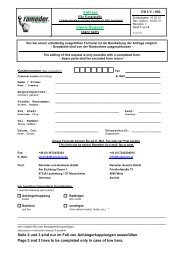
5<br />
max 10 min!!!<br />
6 7<br />
8 9<br />
10.03.2009-02 / Änderungen vorbehalten Seite 5 von 20
<strong>EINBAUANLEITUNG</strong><br />
10<br />
6<br />
7<br />
1 (Bild-picture 6) 4 (Bild-picture 6) 5<br />
2<br />
3<br />
11<br />
10.03.2009-02 / Änderungen vorbehalten Seite 6 von 20
<strong>EINBAUANLEITUNG</strong><br />
12<br />
13<br />
14 15<br />
10.03.2009-02 / Änderungen vorbehalten Seite 7 von 20
<strong>EINBAUANLEITUNG</strong><br />
16 17<br />
40 mm<br />
18<br />
Loch ø 40 mm bohren<br />
Hole ø 40 mm bore<br />
19<br />
Montage Steckdose<br />
assembly pin socket<br />
Modul UN-30/1<br />
connector 14pin<br />
cable bn, wh/bn<br />
20 21<br />
10.03.2009-02 / Änderungen vorbehalten Seite 8 von 20
<strong>EINBAUANLEITUNG</strong><br />
Mj 2009-2010 22-34<br />
22 23<br />
connector E, G<br />
connector E, G<br />
24<br />
25<br />
connector E, G<br />
26 27<br />
connector G pin 7 or/bn<br />
pin 8 or/gn<br />
or/bn<br />
or/gn<br />
pin 3 connector 4pin<br />
pin 1 connector 4pin<br />
10.03.2009-02 / Änderungen vorbehalten Seite 9 von 20
<strong>EINBAUANLEITUNG</strong><br />
28 29<br />
connector E pin 2 rd/bk<br />
connector E<br />
30<br />
31<br />
rd/bk pin 2 connector 4pin e-kit rd/bk pin 2 connector E<br />
32 33<br />
e-kit or/bn<br />
or/gn<br />
pin 7 connector G<br />
pin 8 connector G<br />
connector e-kit 4pin<br />
10.03.2009-02 / Änderungen vorbehalten Seite 10 von 20
<strong>EINBAUANLEITUNG</strong><br />
34<br />
35<br />
Mj 2010- 36-47<br />
connector E, G<br />
36<br />
37<br />
BSG Connector bn<br />
38 39<br />
pin 15 or/gn<br />
pin 17 rd/bk<br />
; pin 16 or/bn<br />
10.03.2009-02 / Änderungen vorbehalten Seite 11 von 20
<strong>EINBAUANLEITUNG</strong><br />
40 41<br />
42<br />
43<br />
Cabel E-Kit or/gn pin 15;<br />
or/bn pin 16; rd/bk pin 17<br />
Cabel Car Cabel Car Socket 4pin; or/gn pin 1;<br />
rd/bk pin 2; or/bn pin 3;<br />
44 45<br />
Socket 4pin<br />
10.03.2009-02 / Änderungen vorbehalten Seite 12 von 20
<strong>EINBAUANLEITUNG</strong><br />
46 47<br />
Connector bn<br />
BSG<br />
48 49<br />
1<br />
2<br />
50 51<br />
3<br />
6<br />
4<br />
5<br />
bu/bk pin 1 - 11 +15<br />
rd pin 22 - 49 +30<br />
5A 1 - 11<br />
15A 22 - 49<br />
10.03.2009-02 / Änderungen vorbehalten Seite 13 von 20
<strong>EINBAUANLEITUNG</strong><br />
52<br />
53<br />
54<br />
10.03.2009-02 / Änderungen vorbehalten Seite 14 von 20
<strong>EINBAUANLEITUNG</strong><br />
55<br />
56<br />
2<br />
1<br />
7 (Bild-picture 58)<br />
5 (Bild-picture 58) 6<br />
3<br />
4<br />
10.03.2009-02 / Änderungen vorbehalten Seite 15 von 20
<strong>EINBAUANLEITUNG</strong><br />
57 58<br />
10.03.2009-02 / Änderungen vorbehalten Seite 16 von 20
<strong>EINBAUANLEITUNG</strong><br />
59 60<br />
61<br />
62<br />
Nummer : 990799<br />
part number : 990799<br />
63<br />
Nummer : 990699<br />
part number : 990699<br />
10.03.2009-02 / Änderungen vorbehalten Seite 17 von 20
<strong>EINBAUANLEITUNG</strong><br />
64<br />
!<br />
65<br />
66<br />
! 3 / C<br />
10.03.2009-02 / Änderungen vorbehalten Seite 18 von 20
<strong>EINBAUANLEITUNG</strong><br />
67<br />
Anhängerbetrieb konfigurieren / Set up trailer operation<br />
D !<br />
Allgemein<br />
Nach einbau des Elektrosatzes sind die obligatorische Anhängerbeleuchtung sowie die in einigen Ländern gesetzlich vorgeschriebene Anhängerblinküberwachung ohne jede Freischaltung am Fahrzeug<br />
gewährleistet!<br />
Es wird jedoch die Meldung „Steuergerät“ falsch codiert im Fehlerspeicher hinterlegt (19 - Diagnoseinterface für Datenbus)! Dieser Eintrag hat allerdings keine Auswirkung auf weitere Funktionen und kann<br />
bis zum nächsten planmäßigen Werkstattaufenthalt ignoriert werden. Wir empfehlen eine Freischaltung mittels herstellerseitigen Service-Testers (VAS 5051 / 5052) im Rahmen der jährlichen<br />
Serviceintervalle!<br />
Passen Sie die Codierung des Fahrzeuges bei folgenden Steuergeräten über die geführte Fehlersuche an, in dem Sie auf „Anhängerkupplung verbaut“ umstellen:<br />
-19 Diagnoseinterface für Datenbus<br />
- lange Codierung lesen/schreiben<br />
- 69 Anhängerfunktion (codieren)<br />
Fahrzeuge mit PDC<br />
Adresswort 76 (Einparkhilfe) -> Anpassung Kanal 2 > 0-30cm (Richtwert 11cm)<br />
Ab Modelljahr 2010- mit Einparkhilfe II oder Parklenkassistent das Steuergerät mit VAS-Tester in der Eigendiagnose codieren:<br />
- Adresswort 10 (Einparkhilfe - Parklenkassistent)<br />
- 08 Codierung (Dienst $22)<br />
- Codierwert ändern: Byte 0 Bit-Muster xxxxxxx1 (x: die vorhandenen Werte ins Eingabefeld abtippen). Dazu auf Eingabemodus [BIN] schalten<br />
-Modelle mit Gespannstabilisierung, diese zwingend aktivieren; ABS-Steuergerät- J104 anpassen:<br />
Fahrzeug auswählen; > weiter (Fahrzeugsystemtest); > weiter; mit „Sprung“ in „Funktions Bauteilauswahl“ Fahrwerk; Bremsanlage; 01-Eigendiagnosefähige Systeme; Antiblockiersystem; Funktionen;<br />
Anpassung-J104 mit Gespannstabilisierung; weiter den Menü-Anweisungen folgen<br />
Fahrzeuge mit Einparkhilfe<br />
Nach erfolgter Freischaltung wird im Anhängerbetrieb auch die rückwärtige Einparkhilfe automatisch deaktiviert!<br />
GB !<br />
Genaral<br />
After the installation of the electric kit, the obligatory trailer lighting as well as the trailer indicator controlwhich is statutory in a several countries are guaranteed wihout having to make any connections on the<br />
vehicle!<br />
The message „Control unit incorrectly coded“ will, however, appear in the fault memory (19 - Diagnosis interface for databus)! Yet this entry has no effect on the other functions and can be ignored until your<br />
next regular service appointment. We recommend the connection via the factory-mounted service tester (VAS 5051 / 5052) with in the framework of the annual service intervals!<br />
Match the vehicle code in the following control units via selected diagnostics by coding „towing hitch installed“:<br />
-19 Diagnosis interface for data bus<br />
- Read/write long coding<br />
- 69 trailer function (code)<br />
Vehicles with park distance Control PDC<br />
adress 76 (park distance control); adjustment; channel 2 > 0-30cm (standard 11cm)<br />
Models as of 2008 – equipped with the parking assist II system, a control device with a VAS test apparatus, should be encoded in the following fashion:<br />
- address word 10 (parking assist)<br />
- encoding 08 (service $22)<br />
- modification of the encoding value: byte 0 reference bit xxxxxxx1 (x: enter the applicable values in the data entry field). In order to do so, please activate the data entry mode [BIN]<br />
10.03.2009-02 / Änderungen vorbehalten Seite 19 von 20
<strong>EINBAUANLEITUNG</strong><br />
GB !<br />
- Modell with trailer stabilisation system; this function must be activated; ABS-control unit-J104 with the selected diagnostics as follows:<br />
Select vehicle; > Continue (vehicle system test); > Continue; > With „Jump“ to „Function-component selection“ Suspension; Break system; 01-Self-diagnosis-capable systems; Anti-blocking system;<br />
Funktions; Adjustment-J104 with trailer stabilisation system; Continue to follow the menu instructions<br />
Vehicles with park assist system<br />
After the effected connection, the rear park assist system will also automatically be deactivated in trailer operation!<br />
I !<br />
Informazioni generali<br />
Dopo il montaggio del elettronico, l'illuminazione obbligatoria e il controllo dei lampeggianti del rimorchio (prescritto dalla legge in alcuni paesi) sono assicurati senza bisogno di alcuna procedura di<br />
attivazione!<br />
Tuttavia, il messaggio di errore „Codifica del dispositivo di controllo non coretta“è registrata nella memoria (19 - Interfaccia di diagnosi per il data bus“)! Questa registrazione non ha comunque alcun effetto<br />
sulle ulteriori funzioni, e può essere ignorata fino alla prossima manutenzione periodica da eseguire in officina. Consigliamo di eseguire l'attivazione con il tester di servizio originale del costruttore<br />
(VAS 5051 / 5052) nel quadro della manutenzione anuale!<br />
Adattare la codifica del veicolo per i seguenti dispositivi di controllo mediante ricerca guasti eseguita, passando a „gancio rimorchio montato“:<br />
-19 interfaccia di diagnosi per bus dati<br />
- lettura/scrittura codifica lunga<br />
- 69 funzione gancio di traino (codifica)<br />
Veicoli di sistema di ausilio di parcheggio PDC<br />
parola di indirizzamento 76 (sistema di ausilio di parcheggio); adattamento; canale 2; 0-30cm (valore indicativo 11cm)<br />
I modelli a partire dal 2008 – dotati di ausilio al parcheggio II o assistente al parcheggio, il dispositivo di controllo dotato di tester VAS viene codificato in modo seguente:<br />
- parola d'indirizzo 10 (ausilio al parcheggio - assistente al parcheggio)<br />
- codifica 08 (servizio $22)<br />
- modifica del valore di codifica: byte di 0 bit campione xxxxxxx1 (x: i valori di riferimento da introdurre nella casella dati). Per questo è necessario attivare il modo d'introduzione di dati [BIN]<br />
-Modello di controllo per facilitare la stabilizzazione del rimorchio; tale funzione deve necessariamente essere attivata; centralina ABS J104 con la ricerca guasti guidata come segue:<br />
Selezionare il veicolo; continuare (est sistema del veicolo); > continuare; Con „Salto“ nella „Selezione elemento di funzionamento“ Autotelaio; Impianto frenante; 01-Sistema adattabile per autodiagnosi;<br />
Sistema antibloccaggio ruote; Funzioni; Adattamento J104 con stabilizzazione del rimorchio; continuare seguendo le istruzioni del menu<br />
Veicoli con sensori di parcheggio<br />
Dopo aver comoletato l'attivazione, i sensori di parcheggio posteriori vengono disattivati automaticamente quando è attaccato un rimorchio!<br />
F !<br />
Généralités<br />
Après l'installation du module électrique, l'éleclairage obligatoire de la remorque ainsi que le contrôle des clignotants de la remorque, prescrit dans certains pays, sont assurés sans qu'il soit nécessaire<br />
dàctiver ces fonctions dans le véhicule!<br />
Toutefois, message sera affiché dans la mémoire dèrreurs (19 - interface de diagnostic pour bus de données)! Or, ce message nà aucune influence sur les<br />
autres fonctions et il n`est pas nécessaire de sèn occuper jusqu`au prochain service prévu dans un garage. Nous vous recommandons dàctiver ces fonctions á l`aide d´un testeur de service du fabricant<br />
(VAS 5051 / 5052) dans le cadre des intervalles de service!<br />
Adaptez le codage du véhicule pour les calculateurs suivants à l'aide de la recherche guidée des défauts en le mettant sur „Dispositif d'attelage posé“:<br />
-19 Diagnostic interface pour bus de données<br />
- Lire/écrire long<br />
- 69 Fonction remorque (coder)<br />
Véhicules avec auxiliaire de stationnement PDC<br />
Mot d'adresse 76 (auxiliare de stationnement); Adaption; Canal 2; 0 à 30cm (valeur indicative 11cm)<br />
Les modèles à partir de 2008 – équipés d’aide au parking II ou l'assistant au parking, le contrôleur doté de testeur VAS est codifié comme suit :<br />
- mot d'adresse 10 (aide au parking - assistant au parking)<br />
- 08 codage (service $22)<br />
- Modification de la valeur de codage: byte de 0 bit échantillon xxxxxxx1 (x : les valeurs de référence à introduire dans la case de données). Pour cela, il est nécessaire d’activer le mode d’introduction de<br />
données [BIN]<br />
- modèle calculateur supportant la stabilisation d'atelage, cette fonction doit obligatoirement être; calculateur J104 pour ABS à l'aide de la recherche guidée des défauts enprocédant comme suite:<br />
Sélectionner le véhicule; > Suivant (Test système du véhicule); > Suivant; Passer à la sélection de composant/fonction avec la fonction „saut“ Châssis; Système de freinage; 01-Systèmes aptes<br />
à l'autodiagnostic; Système antiblocage; Fonctions; Adaptation du J104 avec stabilisation d'attelage; Continuer à suivre les instructions du menu<br />
Véhicules avec système d'aide au parking<br />
Après l'activation, l'aide au parking arrière est également désactivé automatiquement dans le mode remorque!<br />
10.03.2009-02 / Änderungen vorbehalten Seite 20 von 20