Regolatori di velocità monofase serie FCS / FCS series single phase ...
Regolatori di velocità monofase serie FCS / FCS series single phase ...
Regolatori di velocità monofase serie FCS / FCS series single phase ...

Create successful ePaper yourself
Turn your PDF publications into a flip-book with our unique Google optimized e-Paper software.
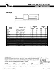
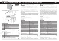
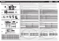
Collegamenti elettrici/Electrical connections<br />
<strong>FCS</strong>M**2300<br />
<strong>FCS</strong>M**23L0<br />
LINE<br />
LINEA<br />
230 Vac<br />
L N<br />
4A<br />
M<br />
LOAD<br />
+ -<br />
+V<br />
0...10 Vdc<br />
Segnale <strong>di</strong> comando<br />
Driving signal<br />
LINE<br />
LINEA<br />
230 Vac<br />
N<br />
L<br />
+ -<br />
0...10 Vdc<br />
Segnale <strong>di</strong> comando<br />
signal<br />
+<br />
Driving<br />
8 e 12 A<br />
M<br />
LOAD<br />
+V<br />
10KΩ<br />
+V<br />
Pilotaggio con<br />
Drivenbypotentiometer<br />
potenziometro<br />
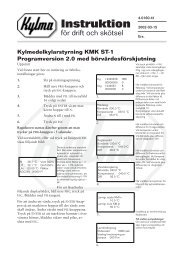
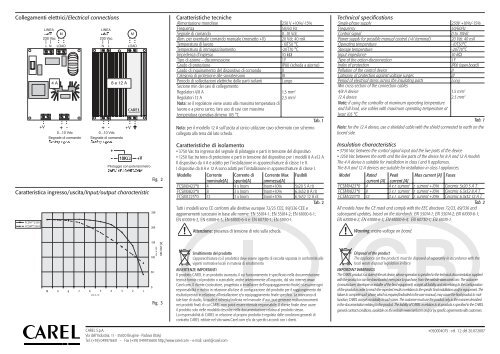
Caratteristica ingresso/uscita/Input/output characteristic<br />
Fig. 2<br />
250<br />
200<br />
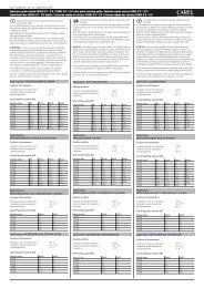
Caratteristiche tecniche<br />
Alimentazione <strong>monofase</strong> 230 V +10%/-15%<br />
Frequenza<br />
50/60 Hz<br />
Segnale <strong>di</strong> comando<br />
0...10 Vdc<br />
Alim. per eventuale comando manuale (morsetto +V) 20 Vdc 40 mA<br />
Temperatura <strong>di</strong> lavoro -10T50 °C<br />
Temperatura <strong>di</strong> immagazzinamento -20T70 °C<br />
Impedenza d’ingresso<br />
10 kΩ<br />
Tipo <strong>di</strong> azione – <strong>di</strong>sconnessione<br />
1Y<br />
Grado <strong>di</strong> protezione<br />
IP00 (scheda a giorno)<br />
Grado <strong>di</strong> inquinamento del <strong>di</strong>spositivo <strong>di</strong> comando II<br />
Categoria <strong>di</strong> protezione alle sovratensioni<br />
III<br />
Periodo <strong>di</strong> sollecitazioni elettriche delle parti isolanti Lungo<br />
Sezione min dei cavi <strong>di</strong> collegamento<br />
<strong>Regolatori</strong> 4/8 A<br />
1,5 mm 2<br />
<strong>Regolatori</strong> 12 A<br />
2,5 mm 2<br />
Nota: se il regolatore viene usato alla massima temperatura <strong>di</strong><br />
lavoro e a pieno carico, fare uso <strong>di</strong> cavi con massima<br />
temperatura operativa almeno 105 °C<br />
Tab. 1<br />
Nota: per il modello 12 A sull’uscita al carico utilizzare cavo schermato con schermo<br />
collegato alla terra dal lato scheda.<br />
Caratteristiche <strong>di</strong> isolamento<br />
• 3750 Vac tra ingresso del segnale <strong>di</strong> pilotaggio e parti in tensione del <strong>di</strong>spositivo<br />
• 1250 Vac tra terra <strong>di</strong> protezione e parti in tensione del <strong>di</strong>spositivo per i modelli 8 A e12 A<br />
Il <strong>di</strong>spositivo da 4 A è adatto per l’installazione in apparecchiature <strong>di</strong> classe I e II.<br />
I <strong>di</strong>spositivi da 8 A e 12 A sono adatti per l’installazione in apparecchiature <strong>di</strong> classe I.<br />
Modello Corrente Corrente <strong>di</strong> Corrente Max Fusibili<br />
nominale[A] spunto[A] ammessa[A]<br />
<strong>FCS</strong>M0423*0 4 4 x Inom Inom+10% 5x20 5 A rit<br />
<strong>FCS</strong>M0823*0 8 3 x Inom Inom+10% 6,3x32 8 A rit<br />
<strong>FCS</strong>M1223*0 12 3 x Inom Inom+10% 6,3x32 12 A rit<br />
Tab. 2<br />
Tutti i modelli sono CE conformi alle <strong>di</strong>rettive europee 72/23 CEE, 89/336 CEE e<br />
aggiornamenti successivi in base alle norme: EN 55014-1; EN 55014-2; EN 61000-6-1;<br />
EN 61000-6-2; EN 61000-6-3; EN 61000-6-4 e: EN 60730-1; EN 61010-1.<br />
Attenzione: presenza <strong>di</strong> tensione <strong>di</strong> rete sulla scheda.<br />
Technical specifications<br />
Single-<strong>phase</strong> supply 230V +10%/-15%<br />
Frequency<br />
50/60Hz<br />
Control signal<br />
0 to 10Vdc<br />
Power supply for possible manual control (+V terminal) 20 Vdc 40 mA<br />
Operating temperature<br />
-10T50°C<br />
Storage temperature<br />
-20T70°C<br />
Input impedance<br />
10 kΩ<br />
Type of the action-<strong>di</strong>sconnection<br />
1Y<br />
Index of protection<br />
IP00 (open board)<br />
Pollution of the control device<br />
II<br />
Category of protection against voltage surges<br />
III<br />
Period of electrical stress across the insulating parts<br />
Long<br />
Min cross-section of the connection cables<br />
4/8 A device<br />
1.5 mm 2<br />
12 A device<br />
2.5 mm 2<br />
Note: if using the controller at maximum operating temperature<br />
and full load, use cables with maximum operating temperature at<br />
least 105 °C<br />
Tab. 1<br />
Note: for the 12 A device, use a shielded cable with the shield connected to earth on the<br />
board side.<br />
Insulation characteristics<br />
• 3750 Vac between the control signal input and the live parts of the device<br />
• 1250 Vac between the earth and the live parts of the device for 8 A and 12 A models<br />
The 4 A device is suitable for installation in class I and II appliances.<br />
The 8 A and 12 A devices are suitable for installation in class I appliances.<br />
Model Rated Peak Max current [A] Fuses<br />
current [A] current [A]<br />
<strong>FCS</strong>M0423*0 4 4 x r. current r. current +10% Ceramic 5x20 5 A T.<br />
<strong>FCS</strong>M0823*0 8 3 x r. current r. current +10% Ceramic 6.3x32 8 A T.<br />
<strong>FCS</strong>M1223*0 12 3 x r. current r. current +10% Ceramic 6.3x32 12 A T.<br />
Tab. 2<br />
All models have the CE mark and comply with the EEC <strong>di</strong>rectives 72/23, 89/336 and<br />
subsequent updates, based on the standards: EN 55014-1; EN 55014-2; EN 61000-6-1;<br />
EN 61000-6-2; EN 61000-6-3; EN 61000-6-4; EN 60730-1; EN 61010-1.<br />
Warning: mains voltage on board.<br />
10<br />
9<br />
8<br />
7<br />
6<br />
Vdc 0-10<br />
5<br />
4<br />
3<br />
2<br />
1<br />
150<br />
100<br />
50<br />
0<br />
Vac 0-230<br />
VAC OUT [V]<br />
Fig. 3<br />
Smaltimento del prodotto<br />
L’apparecchiatura (o il prodotto) deve essere oggetto <strong>di</strong> raccolta separata in conformità alle<br />
vigenti normative locali in materia <strong>di</strong> smaltimento<br />
AVVERTENZE IMPORTANTI<br />
Il prodotto CAREL è un prodotto avanzato, il cui funzionamento è specifi cato nella documentazione<br />
tecnica fornita col prodotto o scaricabile, anche anteriormente all’acquisto, dal sito internet www.<br />
Carel.com. Il cliente (costruttore, progettista o installatore dell’equipaggiamento fi nale) si assume ogni<br />
responsabilità e rischio in relazione alla fase <strong>di</strong> confi gurazione del prodotto per il raggiungimento dei<br />
risultati previsti in relazione all’installazione e/o equipaggiamento fi nale specifi co. La mancanza <strong>di</strong><br />
tale fase <strong>di</strong> stu<strong>di</strong>o, la quale è richiesta/in<strong>di</strong>cata nel manuale d’uso, può generare malfunzionamenti<br />
nei prodotti fi nali <strong>di</strong> cui CAREL non potrà essere ritenuta responsabile. Il cliente fi nale deve usare<br />
il prodotto solo nelle modalità descritte nella documentazione relativa al prodotto stesso.<br />
La responsabilità <strong>di</strong> CAREL in relazione al proprio prodotto è regolata dalle con<strong>di</strong>zioni generali <strong>di</strong><br />
contratto CAREL e<strong>di</strong>tate nel sito www.Carel.com e/o da specifi ci accor<strong>di</strong> con i clienti.<br />
Disposal of the product<br />
The appliance (or the product) must be <strong>di</strong>sposed of separately in accordance with the<br />
local waste <strong>di</strong>sposal legislation in force<br />
IMPORTANT WARNINGS<br />
The CAREL product is a state-of-the-art device, whose operation is specified in the technical documentation supplied<br />
with the product or can be downloaded, even prior to purchase, from the website www.carel.com. The customer<br />
(manufacturer, developer or installer of the final equipment) accepts all liability and risk relating to the configuration<br />
of the product in order to reach the expected results in relation to the specific final installation and/or equipment. The<br />
failure to complete such <strong>phase</strong>, which is required/in<strong>di</strong>cated in the user manual, may cause the final product to malfunction;<br />
CAREL accepts no liability in such cases. The customer must use the product only in the manner described<br />
in the documentation relating to the product. The liability of CAREL in relation to its products is specified in the CAREL<br />
general contract con<strong>di</strong>tions, available on the website www.carel.com and/or by specific agreements with customers.<br />
CAREL S.p.A.<br />
Via dell’Industria, 11 - 35020 Brugine - Padova (Italy)<br />
Tel. (+39) 0499716611 – Fax (+39) 0499716600 http://www.carel.com – e-mail: carel@carel.com<br />
+050004075 - rel. 1.2 del 20.07.2007