Series P78
Series P78
Series P78

Create successful ePaper yourself
Turn your PDF publications into a flip-book with our unique Google optimized e-Paper software.
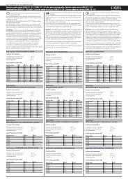
PSC9705<br />
European Refrigeration Controls Catalogue<br />
Catalog Section 6<br />
Product Bulletin <strong>P78</strong><br />
Issue 01 2007<br />
Introduction<br />
PRODUCT BULLETIN<br />
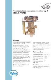
<strong>Series</strong> <strong>P78</strong><br />
Dual Pressure Controls for Refrigeration,<br />
Air-conditioning and Heatpump Applications<br />
These dual pressure controls are designed for<br />
use in a variety of applications involving<br />
refrigeration high or low pressure. Models<br />
supplied have a “whole range” design, enabling<br />
them to be used with refrigerants R22, R134A,<br />
R404A and all other non-corrosive refrigerants<br />
which are within the operating range of the<br />
control. They may also be used for other high or<br />
low pressure applications such as air, water etc.<br />
Models which can be used with ammonia are<br />
included in the program. Also models tested<br />
and approved to PED 97/23/EC Cat. IV<br />
(supersedes DIN and TUV approval) are<br />
included in the program.<br />
Description<br />
The <strong>P78</strong> series pressure controls may be used<br />
for control functions or limit functions,<br />
depending on model number. All models are<br />
provided with alarm contacts (except <strong>P78</strong>ALA).<br />
All standard models have phosphor bronze<br />
bellows and brass pressure connections.<br />
Models for use with ammonia are provided with<br />
stainless steel bellows and connectors.<br />
Devices conforming to PED 97/23/EC Cat. IV<br />
(HP models) have the fail-safe function with<br />
double bellows. Their IP54 classification means<br />
that these pressure controls are suitable for<br />
almost all applications.<br />
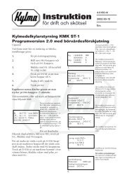
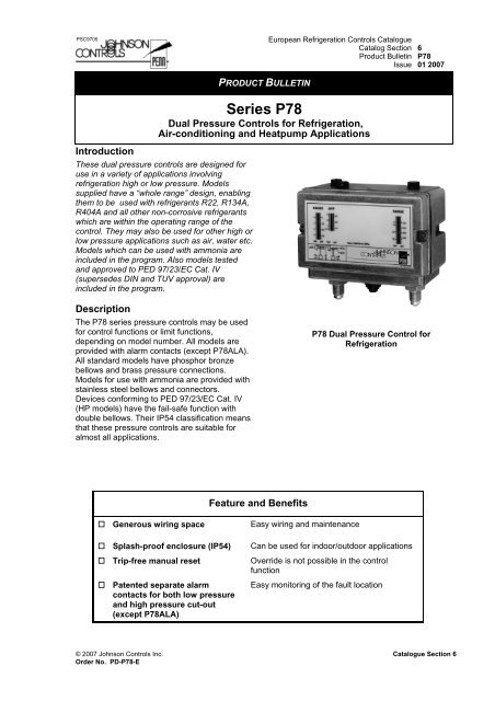
<strong>P78</strong> Dual Pressure Control for<br />
Refrigeration<br />
Feature and Benefits<br />
Generous wiring space<br />
Splash-proof enclosure (IP54)<br />
Trip-free manual reset<br />
Patented separate alarm<br />
contacts for both low pressure<br />
and high pressure cut-out<br />
(except <strong>P78</strong>ALA)<br />
Easy wiring and maintenance<br />
Can be used for indoor/outdoor applications<br />
Override is not possible in the control<br />
function<br />
Easy monitoring of the fault location<br />
© 2007 Johnson Controls Inc. Catalogue Section 6<br />
Order No. PD-<strong>P78</strong>-E
2<br />
Note<br />
The controls are intended to control<br />
equipment under normal operating<br />
conditions. Where failure or malfunctioning<br />
of the controls could lead to an abnormal<br />
operating condition that could cause<br />
personal injury or damage to the<br />
equipment or other property, other devices<br />
(limit or safety controls) or systems (alarm<br />
or supervisory systems) intended to warn<br />
of or protect against failure or<br />
malfunctioning of the controls must be<br />
incorporated into and maintained as part of<br />
the control system.<br />
Note<br />
To facilitate order handling special<br />
ordering codes have been added to some<br />
commonly used models<br />
Type number matrix<br />
<strong>P78</strong>LCA Automatic reset both sides<br />
<strong>P78</strong>MCA Automatic reset low side<br />
manual reset high side<br />
<strong>P78</strong>PGA Manual reset both sides<br />
<strong>P78</strong>LCW Automatic reset both sides<br />
conform PED 97/23/CE<br />
<strong>P78</strong>MCB Automatic reset low side<br />
manual reset high side<br />
conform PED 97/23CE<br />
<strong>P78</strong>MCS Automatic reset low side<br />
manual reset high side<br />
conform PED 97/23/CE<br />
<strong>P78</strong>PGB Manual reset both sides<br />
conform PED 97/23/CE<br />
<strong>P78</strong>PLM 2 x manual rest HP<br />
conform PED 97/23/CE<br />
<strong>P78</strong>ALA Dual fan cycling control<br />
(2 x SPST close high)<br />
Adjustment<br />
On most models the range scale indicates the<br />
high switch point (exception: LP side of<br />
<strong>P78</strong>PGA,<strong>P78</strong>PGB, here the range scale<br />
indicates the low switching point). To obtain low<br />
switch point deduct differential value from the<br />
high switch point.<br />
Repair and replacement<br />
Repair is not possible. In case of an improperly<br />
functioning control, please check with your<br />
nearest supplier. When contacting the supplier<br />
for a replacement you should state the<br />
type/model number of the control. This number<br />
can be found on the data plate or cover label.<br />
<strong>P78</strong><br />
Issue 01 2007<br />
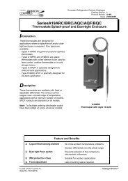
Contact functions<br />
(see also “Type Number Selection” table)<br />
A<br />
Line ~<br />
max. 20 A<br />
LP.<br />
HP.<br />
Line ~<br />
max. 20 A<br />
LP<br />
HP<br />
D<br />
C<br />
A - C opens on pressure decrease<br />
A - B closes simultaneously<br />
A - C opens on pressure increase<br />
A - D closes simultaneously<br />
A<br />
Fig. 1<br />
HP<br />
Left side HP. A - C opens on pressure increase<br />
A - B closes simultaneously<br />
Right side HP. A - C opens on pressure increase<br />
A - D closes simultaneously<br />
A - D closed<br />
(fan 2 ON)<br />
A - D open<br />
(fan 2 OFF)<br />
A - B closed<br />
(fan 1 ON)<br />
A - B open<br />
(fan 1 OFF)<br />
Line ~<br />
Fig. 2<br />
HP<br />
Switching action <strong>P78</strong>ALA<br />
max. 20 A<br />
A<br />
D<br />
S1<br />
cut-in point<br />
fan 1<br />
D<br />
D = diferential per stage (fixed)<br />
Fig.3a<br />
HP<br />
B<br />
B<br />
S2<br />
cut-in point<br />
fan 2<br />
HP<br />
B<br />
D<br />
C<br />
M<br />
P<br />
pressure<br />
increase<br />
D<br />
M<br />
M1<br />
M2<br />
Fig. 3b<br />
Catalogue Section 6<br />
© 2007 Johnson Controls Inc.<br />
Order No. PD-<strong>P78</strong>-E
<strong>P78</strong><br />
Issue 01 2007<br />
3<br />
Type number selection table<br />
Dual pressure controls for Non-corrosive refrigerants. LP Pmax.: 22bar HP Pmax.:33 bar<br />
Dual pressure controls for Ammonia and Non-corrosive refrigerants,<br />
LP Pmax.: 20 bar HP Pmax.:33 bar<br />
Dual pressure Fan cycling controls for Air-cooled condensers (Non-corrosive refrigerants)<br />
HP Pmax.: 30 bar<br />
Dual pressure controls for Non-corrosive refrigerants,<br />
(Wächter, Begrenzer, Sicherheitsdruckbegrenzer including lockplate assy)<br />
(Except <strong>P78</strong>PGB-*). LP Pmax.: 20 bar HP Pmax.:33 bar<br />
Family Code Pressure Connection Left Side Right Side Contact Construction<br />
function<br />
Style 5 Style 30 Range Diff. Range Diff. (Figure)<br />
(bar) (bar) (bar) (bar)<br />
Ind.<br />
Pack.<br />
Code*** Bulkpack<br />
Ind.<br />
Pack.<br />
<strong>P78</strong>LCA -9300 <strong>P78</strong>L -9320 -9400 -0.5 to 7 0.5 to 3 3 to 30 3 (fixed) 1<br />
<strong>P78</strong>MCA -9300 <strong>P78</strong>M -9320 -9400 -0.5 to 7 0.5 to 3 3 to 30 Man.<br />
1 LP/HP<br />
res.**<br />
*** Wholesaler code only for individual pack<br />
** Resetable at 3 bar below cut-out point<br />
* Resetable at 0.5 bar above cut-out point<br />
Family Code Pressure Connection Left Side Right Side Contact Construction<br />
Style 15<br />
Range<br />
(bar)<br />
Diff.<br />
(bar)<br />
Range<br />
(bar)<br />
Diff.<br />
(bar)<br />
function<br />
(Figure)<br />
Ind.<br />
Pack.<br />
Code*** Bulkpack<br />
<strong>P78</strong>LCA -9700 **** -0.5 to 7 0.5 to 3 3 to 30 3 (fixed) 1<br />
<strong>P78</strong>MCA -9700 **** -0.5 to 7 0.5 to 3 3 to 30 Man. res.** 1 LP/HP<br />
<strong>P78</strong>PGA -9700 **** -0.5 to 7 Man. res.** 3 to 30 Man. res.** 1<br />
**** Can be set-up for quantity orders<br />
*** Wholesaler code only for individual package<br />
** Resetable at 3 bar below cut-out point<br />
* Resetable at 0.5 bar above cut-out point<br />
Family Code Pressure Connection Left Side Right Side Contact Construction<br />
Style 5 Style 30 Range<br />
(bar)<br />
Diff.<br />
(bar)<br />
Range<br />
(bar)<br />
Diff.<br />
(bar)<br />
function<br />
(Figure)<br />
Ind.<br />
Pack.<br />
Code*** Bulkpack<br />
Ind.<br />
Pack.<br />
<strong>P78</strong>ALA -9351 <strong>P78</strong>A **** -9451 3.5 to 21 1.8 (fixed) 3.5 to 21 1.8 (fixed) 3 HP/HP<br />
**** Can be set-up for quantity orders<br />
*** Wholesaler code only for individual package<br />
Note: 100 kPa = 1 bar ≈ 14.5 psi<br />
Family Code Pressure Connection Left Side Right Side Contact<br />
function<br />
Approved<br />
according<br />
Style 5 Style 28 Range Diff. Range Diff. (Figure) to PED<br />
(bar) (bar) (bar) (bar)<br />
97/23EC<br />
Ind. Code*** Bulkpack<br />
Ind.<br />
Cat. IV<br />
Pack.<br />
Pack.<br />
<strong>P78</strong>LCW -9300 <strong>P78</strong>W -9320 -9800 -0.5 to 7 0.5 to 3 3 to 30 3 (fixed) 1 Yes<br />
<strong>P78</strong>MCB -9300 <strong>P78</strong>B -9320 -9800 -0.5 to 7 0.5 to 3 3 to 30 Man. res.** 1 Yes<br />
<strong>P78</strong>MCS -9300 <strong>P78</strong>S -9320 -9800 -0.5 to 7 0.5 to 3 3 to 30 Man. res.** 1 Yes<br />
<strong>P78</strong>PGB -9300 <strong>P78</strong>P **** -9800 -0.5 to 7 Man. res.* 3 to 30 Man. res.** 1 Yes<br />
<strong>P78</strong>PLM -9350 <strong>P78</strong>BS **** -9850 3 to 30 Man. res.** 3 to 30 Man. res.** 2 Yes<br />
**** Can be set up for quantity orders<br />
*** Wholesaler code only for individual pack<br />
** Resetable at 3.5 bar below cut-out point<br />
* Resetable at 0.5 bar above cut-out point<br />
© 2007 Johnson Controls Inc. Catalogue Section 6<br />
Order No. PD-<strong>P78</strong>-E
4<br />
<strong>P78</strong><br />
Issue 01 2007<br />
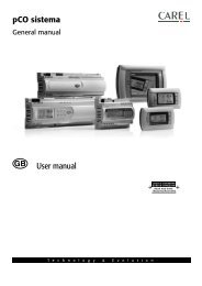
Pressure connections<br />
Fig. 4<br />
Style 5<br />
Male connector<br />
7<br />
/16"-20 UNF for 1/4"<br />
6 mm flare nut.<br />
Fig. 5<br />
Style 15<br />
Female connector<br />
1<br />
/4"-18 NPT<br />
Fig. 6<br />
Style 28<br />
Braze connection<br />
6 mm ODM<br />
Fig. 7<br />
Style 30<br />
Braze connection<br />
1/4" ODF<br />
Accessories (optional)<br />
Fig. 8<br />
Description Application Order number<br />
Fits into style 15 For 6 mm copper or steel tubing CNR003N001R<br />
pressure connectors For 8 mm copper or steel tubing CNR003N002R<br />
Fig. 9<br />
Mounting bracket<br />
Order number 271-51L<br />
Fig. 10<br />
90 cm Capillary with (2) flare<br />
nuts (1/4" SAE)<br />
Order number SEC002N600<br />
Fig. 11<br />
Locking kit<br />
Order number KIT023N600<br />
Catalogue Section 6<br />
© 2007 Johnson Controls Inc.<br />
Order No. PD-<strong>P78</strong>-E
<strong>P78</strong><br />
Issue 01 2007<br />
5<br />
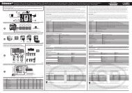
Dimensions (mm)<br />
1. lock plate (if applied)<br />
2. two mounting holes Ø 4.5 mm (knock out)<br />
3. four mounting holes Ø M4 (back side)<br />
4. cable inlet grommet (cable range Ø 5 to Ø 13 mm)<br />
5. power element:<br />
Style 5: 7 /16"-20 UNF male (shown)<br />
Style 15: 1 /4"-18 NPT female<br />
6. reset button<br />
Fig. 12<br />
© 2007 Johnson Controls Inc. Catalogue Section 6<br />
Order No. PD-<strong>P78</strong>-E
6<br />
<strong>P78</strong><br />
Issue 01 2007<br />
Dimensions (mm)<br />
53<br />
70<br />
9<br />
25<br />
48.5<br />
10 55<br />
8<br />
16.5<br />
25<br />
13<br />
10<br />
110 80 5.5<br />
1<br />
2<br />
3<br />
4<br />
5<br />
75<br />
122<br />
61<br />
23.5<br />
53 6<br />
6<br />
26<br />
1. 5 21.5<br />
1. lock plate (if applied)<br />
2. two mounting holes Ø 4.5 mm (knock out)<br />
3. four mounting holes Ø M4 (back side)<br />
4. cable inlet grommet (cable range Ø 5 to Ø 13 mm)<br />
5. power element:<br />
Style 28: Braze connection 6 mm ODM (shown)<br />
Style 30: Braze connection 1/4" ODF<br />
6. reset button<br />
Fig. 13<br />
Catalogue Section 6<br />
© 2007 Johnson Controls Inc.<br />
Order No. PD-<strong>P78</strong>-E
<strong>P78</strong><br />
Issue 01 2007<br />
7<br />
Notes<br />
© 2007 Johnson Controls Inc. Catalogue Section 6<br />
Order No. PD-<strong>P78</strong>-E
8<br />
<strong>P78</strong><br />
Issue 01 2007<br />
Technical Specifications<br />
Pressure connections Style 5, 15, 28, 30 (see drawings)<br />
Operating ranges and diff. See type number selection<br />
Adjustments See type number selection<br />
Ambient temp. limit -50 to +55 °C (+70 °C max. duration two hours)<br />
-20 to +55 °C for PED approved models<br />
Electrical ratings 400 Vac contact A-C 16(10) A<br />
contact A-B 8(5) A<br />
contact A-D 8(5) A<br />
220 Vdc 12 W (pilot duty only)<br />
Pulsation plug Fitted into all HP bellows<br />
Locking plate and screw To lock and seal range and/or differential screw.<br />
Standard on types <strong>P78</strong>LCW, MCB, MCS, PGB and PLM.<br />
Optional on all other types (quantity orders only)<br />
Protection Class IP54<br />
Material Case and cover Weatherproof aluminium (die-cast)<br />
Contact unit<br />
Mounting bracket<br />
Compression coupling<br />
90 cm capillary with two flare nuts<br />
Shipping weight ind. pack 0.8 kg<br />
Accessories (see pag. 4)<br />
{<br />
Large copper-backed silver cadmium contacts<br />
(AgCdO) on conductor leaves<br />
-93xx Ind. overpack 30 pcs. (24.5 kg)<br />
-97xx Bulk pack 24 pcs. (19.5 kg)<br />
-94xx Ind. overpack 13 pcs. (11 kg)<br />
{<br />
-98xx<br />
The performance specifications are nominal and conform to acceptable industry standards. For applications at conditions beyond<br />
these specifications, consult the local Johnson Controls office or representative. Johnson Controls shall not be liable for damages<br />
resulting from misapplication or misuse of its products.<br />
Johnson Controls International, Inc.<br />
Headquarters:<br />
Milwaukee, Wisconsin, USA<br />
Branch Offices:<br />
Principal Cities World-wide<br />
This document is subject to change<br />
Catalogue Section 6<br />
www.johnsoncontrols.com<br />
Printed in Europe<br />
© 2007 Johnson Controls Inc.<br />
Order No. PD-<strong>P78</strong>-E