Warmluft-Hände- und Haartrockner - Starmix
Warmluft-Hände- und Haartrockner - Starmix
Warmluft-Hände- und Haartrockner - Starmix

Create successful ePaper yourself
Turn your PDF publications into a flip-book with our unique Google optimized e-Paper software.
Installation instructions<br />
The installation must be carried out by qualified personnel to ensure<br />
that the appliance is connected in accordance with safety regulations.<br />
In rooms with showers and bath tubs the appliance must be installed<br />
with the minimum distances laid down in the VDE regulations (0.6 mtrs<br />
(24 inches) from the edge of the shower and/or bath and 1.2 mtrs (48<br />
inches) from a shower head).<br />
Installation sequence<br />
The maintenance-friendly installation concept<br />
The TT1800 installation system enables simple, maintenance-friendly<br />
wall mounting without having to open up the appliance. For ease of<br />
installation, we have separated the appliance into two components:<br />
The installer installs a socket (or a permanent connection), screws the<br />
mounting plate on, slides the ready-to-use appliance onto it, inserts the<br />
mains plug into the socket (or connects), screws the anti-theft cover plate<br />
on – finished. It’s as easy as that!<br />
1.<br />
.<br />
.<br />
a)<br />
)<br />
c)<br />
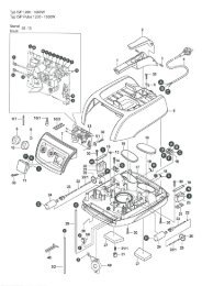
Pull the cover plate [ 1 ] (not screwed on) down and out of the<br />
appliance. Pull the mounting plate [ 2 ] which has been inserted<br />
at the back of the appliance downwards and out.<br />
Confirm where the appliance is to be located, mark the 4 fixing<br />
holes [ 12 ], using mounting plate [ 2 ] as a template, drill the<br />
holes (8 mm Ø), insert the dowels and fix the mounting plate<br />
with the enclosed button-head wood screw A. We recommend<br />
mounting heights as shown in figures A, B or C. It must be<br />
ensured that the appliance is firmly secured to a solid wall.<br />
There are 5 different ways to connect the appliance as<br />
described below.<br />
Mounting via an installed flush socket.<br />
The upper part of the cover plate [ 1 ] is not required. Break<br />
it off at the predetermined breaking point [ 4 ]. When the<br />
mounting plate [ 2 ] has been fixed, push the appliance onto to<br />
the mounting plate from the top as shown in figure B , insert<br />
the plug into the socket [ 3 ] <strong>und</strong> push the appliance all the way<br />
down. Fasten the cover plate with the 2 enclosed countersunk<br />
flat head tapping screws.<br />
Concealed wiring<br />
Connection via wiring concealed in the wall [ 7 ](instead of a<br />
socket). Fix mounting plate [ 2 ] to wall as shown in fig. C. Slide<br />
the cover plate into the mounting plate from below and route<br />
the wiring from the wall through the opening in the cover plate.<br />
Insert the attached terminal [ 11 ]. Cut the plug at the connection<br />
lead [ 5 ] of the appliance, strip the cable and, squeeze the wire<br />
end ferrules on. Connect both lead as shown in fig. C. Ensure<br />
that L (brown) and N (blue) are connected correctly. Secure the<br />
connecting lead of the appliance with the enclosed strain-relief<br />
clamp [ 8 ]. Push appliance fully down onto the cover plate and<br />
screw in the 2 enclosed countersunk flat head tapping screws.<br />
Surface mount wiring from above<br />
Break out the wiring lead through at the rear of the appliance,<br />
top centre. When the mounting plate [ 2 ] has been attached as<br />
shown in fig. C, route the surface mount wiring on the mounting<br />
plate down <strong>und</strong>er the cover plate [ 1 ] and through the opening.<br />
Continue with the connection as described in the 2nd paragraph<br />
<strong>und</strong>er B.<br />
d)<br />
e)<br />
...mehr als Sie denken!<br />
Surface mount wiring from below<br />
On the cover plate [ 1 ], bottom centre, break out the wiring lead<br />
through [ 9 ]. When the mounting plate [ 2 ] has been attached<br />
as shown in fig. C, route the surface mount wiring through the<br />
opening in the cover plate. Continue with the connection as<br />
described in the 2nd paragraph <strong>und</strong>er B.<br />
Connecting lead with plug.<br />
Connection to a nearby socket with a flexible connecting lead<br />
with plug. On the cover plate [ 1 ], bottom centre, break out the<br />
wiring lead through [ 9 ]. Slide the cover plate into the mounting<br />
plate from below. Insert the attached terminal [ 11 ]. Cut the plug<br />
at the connection lead [ 5 ] of the appliance, strip the cable and,<br />
squeeze the wire end ferrules on. Prepare the connecting lead<br />
with the plug in the same way and route through the opening in<br />
the cover plate. Connect both wires as shown in fig. C and secure<br />
with the enclosed strain relief clamps [ 8 ]. Push appliance<br />
fully down onto the cover plate and screw in the 2 enclosed<br />
countersunk flat head tapping screws.<br />
The appliances are now operational.<br />
Switching options<br />
Operate electronic timer switch on TT 1800 and TTH 1800. The time<br />
delay for TT 1800 is 32 secs. and, for TT 1800 E, 4 mins.<br />
The appliances will switch off automatically.<br />
TT 1800 E, TTH 1800 E Active Oxygen / scent, TTH1800 E<br />
The appliances are operated without touching via infrared proximity<br />
switches.<br />
The switching distance (distance between the <strong>und</strong>erside of the appliance<br />
and hands and/or head) is approx. 15 cm (6 inches) for the TT<br />
1800 and approx. 40 cm (16 inches) for the TTH 1800 E. The switching<br />
sensitivity can be changed by a technician.<br />
Safety cut-out sensor<br />
TT 1800 E, TTH 1800 E<br />
The integrated electronics prevent continuous operation if the infrared<br />
proximity switch has been covered, e.g. due to chewing gum vandalism<br />
TT 1800 E-models will switch off after 4 mins and TTH 1800 E models<br />
after 10 mins. After the source of interference has been removed, the<br />
dryers are operational again.<br />
18