MANUALE D'ISTRUZIONI TECHNICAL MANUAL - Brasilia
MANUALE D'ISTRUZIONI TECHNICAL MANUAL - Brasilia
MANUALE D'ISTRUZIONI TECHNICAL MANUAL - Brasilia

You also want an ePaper? Increase the reach of your titles
YUMPU automatically turns print PDFs into web optimized ePapers that Google loves.
ROMA<br />
<strong><strong>MANUAL</strong>E</strong> D’ISTRUZIONI<br />
<strong>TECHNICAL</strong> <strong>MANUAL</strong><br />
ATTENZIONE: LEGGERE LE ISTRUZIONI<br />
CAREFULLY READ THE INSTRUCTIONS<br />
BRASILIA S.p.A. - STRADA PROVINCIALE BRESSANA-SALICE - 27050 RETORBIDO (PV) ITALY<br />
Tel.+39.0383.372011 - Fax +39.0383.374450 - www.brasilia.it - info@brasilia.it
DATI GENERALI - GENERAL DATA<br />
COSTRUTTORE - MANUFACTURER:<br />
BRASILIA S.p.A. Strada Provinciale Bressana - Salice<br />
27050 Retorbido (PV) Italia<br />
Tel.: + 39.383.372011 Fax: + 39.383.374450<br />
www.brasilia.it - info@brasilia.it<br />
MODELLO - MODEL:<br />
ROMA<br />
ROMA PLUS<br />
ROMA CAPPUCCINO<br />
VERSIONI - VERSIONS:<br />
Digit / P<br />
TIMBRO RAPPRESENTANTE LOCALE:<br />
SERVICE COMPANY STAMP:<br />
Rev. N. Data Note<br />
0 05/2004 EMISSIONE DOCUMENTO<br />
1 09/2004 REVISIONE GENERALE<br />
2 03/2006 AGGIUNTO MODELLO ROMA PLUS<br />
3 09/2006 AGGIUNTO MODELLO ROMA CAPPUCCINO<br />
4 01/2007 AGGIUNTO SERIGRAFIA SUI PORTACOMANDI<br />
REV.4 01/2007<br />
ITALIANO - 1
INDICE<br />
1. SICUREZZA E AVVERTENZE .....................................................................................................................................................................................3<br />
2. INTRODUZIONE ...........................................................................................................................................................................................................4<br />
2.A. COMPONENTI INTERNI MODELLO ROMA .......................................................................................................................................................4<br />
2.B. COMPONENTI INTERNI MODELLO ROMA PLUS ............................................................................................................................................5<br />
2.C. COMPONENTI INTERNI MODELLO ROMA CAPPUCCINO..............................................................................................................................5<br />
3. DESCRIZIONE COMPONENTI.....................................................................................................................................................................................6<br />
3.A. DESCRIZIONE MODELLO ROMA ......................................................................................................................................................................6<br />
3.B. DESCRIZIONE MODELLO ROMA PLUS............................................................................................................................................................7<br />
3.C. DESCRIZIONE MODELLO ROMA CAPPUCCINO .............................................................................................................................................8<br />
SEZIONE “A” – ISTALLAZIONE E MANUTENZIONE .........................................................................................................9<br />
4. ISTALLAZIONE E COLLEGAMENTI .........................................................................................................................................................................10<br />
4.A. COME RIMUOVERE LA MACCHINA DALL’IMBALLO....................................................................................................................................10<br />
4.B. DATI GENERALI COLLEGAMENTI ..................................................................................................................................................................10<br />
4.C. COLLEGAMENTO IDRAULICO ........................................................................................................................................................................11<br />
4.D. COLLEGAMENTO ELETTRICO........................................................................................................................................................................11<br />
4.D.1. COLLEGAMENTO EQUIPOTENZIALE: ...................................................................................................................................................11<br />
5. PROCEDURE DI FUNZIONAMENTO ........................................................................................................................................................................12<br />
5.A. MESSA IN FUNZIONE .......................................................................................................................................................................................12<br />
5.B. MESSA IN FUNZIONE VERSIONE CON IMPIANTO A GAS ...........................................................................................................................12<br />
5.C. REGOLAZIONI...................................................................................................................................................................................................13<br />
6. PROGRAMMAZIONE DOSI VERSIONE DIGIT .........................................................................................................................................................14<br />
6.A. PROGRAMMAZIONE DOSI MODELLI ROMA E ROMA PLUS .......................................................................................................................14<br />
6.B. PROGRAMMAZIONE DOSI MODELLO ROMA CAPPUCCINO ......................................................................................................................15<br />
6.C. PROGRAMMAZIONE DOSE CAFFÈ MACINATO - MODELLO ROMA PLUS ................................................................................................15<br />
6.D. PROGRAMMAZIONE LITRI ACQUA FILTRATA - SOLO PER MODELLI ROMA PLUS ................................................................................15<br />
6.E. PROGRAMMAZIONE PREINFUSIONE - SOLO PER MODELLI ROMA PLUS ...............................................................................................16<br />
7. MALFUNZIONAMENTI E SOLUZIONI .......................................................................................................................................................................16<br />
8. MANUTENZIONE........................................................................................................................................................................................................18<br />
8.A. ISTRUZIONI PER SCARICARE L'ACQUA DELLA CALDAIA MODELLI ROMA E ROMA PLUS..................................................................18<br />
8.B. ISTRUZIONI PER LA RIGENERAZIONE DEL DEPURATORE........................................................................................................................18<br />
SEZIONE “B” – ISTRUZIONI PER L’UTILIZZATORE........................................................................................................20<br />
9. DESCRIZIONE EROGAZIONE BEVANDE ................................................................................................................................................................21<br />
9.A. EROGAZIONE CAFFÈ.......................................................................................................................................................................................21<br />
9.B. EROGAZIONE CAFFÉ - MODELLI ROMA PLUS.............................................................................................................................................22<br />
9.C. COME FARE IL CAPPUCCINO.........................................................................................................................................................................22<br />
9.D. EROGAZIONE VAPORE E ACQUA.................................................................................................................................................................22<br />
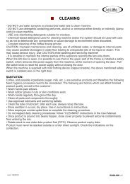
10. PULIZIA.....................................................................................................................................................................................................................23<br />
10.A. PREVENZIONE SANITARIA ...........................................................................................................................................................................23<br />
10.B. PERAZIONI DI PULIZIA GIORNALIERA ........................................................................................................................................................23<br />
10.C. OPERAZIONI DI PULIZIA SETTIMANALI.......................................................................................................................................................23<br />
11. SMANTELLAMENTO ...............................................................................................................................................................................................24<br />
SEZIONE “C” - Dati Tecnici, Schemi Elettrici ed Idraulici ............……………………………..………………….……….. 1<br />
REV.4 01/2007<br />
ITALIANO - 2
1. SICUREZZA E AVVERTENZE<br />
BRASILIA S.p.A. ha preso ogni possibile precauzione per un funzionamento sicuro e un’attrezzatura efficiente. I dispositivi<br />
di sicurezza incorporati, che fanno parte della dotazione BRASILIA, mirano a proteggere gli operatori ed i tecnici autorizzati.<br />
• NON far funzionare la macchina senza aver prima letto le informazioni contenute nel presente manuale. L’inosservanza di questa i-<br />
struzione può causare danni all’attrezzatura, scarse prestazioni della macchina, rischi per la salute o danni personali.<br />
Il presente manuale è da considerarsi parte integrante della macchina e deve essere sempre a disposizione dell’utilizzatore e/o manutentore.<br />
In caso di smarrimento o di richiesta di ulteriori informazioni, contattare il rivenditore di zona o il costruttore. Il manuale rispecchia<br />
lo stato della tecnica al momento attuale e non può essere considerato inadeguato per eventuali successivi aggiornamenti: il costruttore<br />
si riserva il diritto di modificare il manuale senza l’obbligo di aggiornare le edizioni precedenti, salvo casi eccezionali.<br />
Le immagini, riportate nel presente manuale, sono esclusivamente esplicative e potrebbero non rispecchiare l’estetica di tutti<br />
i modelli a cui si riferiscono le istruzioni.<br />
• NON far funzionare la macchina senza rispettare le regole di sicurezza in vigore nel paese d’installazione, così come le regole dettate<br />
dal comune buonsenso. Accertarsi che le operazioni di manutenzione vengano effettuate regolarmente e correttamente.<br />
• NON far funzionare la macchina in assenza di collegamento di messa a terra. L’inosservanza di questa istruzione può dare luogo a<br />
scosse elettriche.<br />
• NON sostituire o rimuovere le istruzioni di sicurezza ed i dati tecnici affissi direttamente sulla macchina e sull’imballo, per<br />
un’installazione ed un utilizzo corretti e sicuri.<br />
• NON toccare gruppi o beccucci durante il funzionamento della macchina. Le lance devono essere maneggiate soltanto tramite apposite<br />
impugnature. Le bevande erogate e alcune parti della macchina sono calde e possono causare ustioni.<br />
• NON toccare tasti o interruttori durante il ciclo di erogazione.<br />
• NON rimuovere o manomettere alcun elemento della macchina e NON effettuare modifiche arbitrarie. Contattare il tecnico autorizzato<br />
e specializzato di zona.<br />
• NON tirare il cavo di alimentazione elettrica per disinserire la spina.<br />
• NON lasciare che la macchina venga usata da bambini o personale inadatto.<br />
• NON esporre la macchina agli agenti atmosferici (sole, pioggia ecc...).<br />
• NON far funzionare la macchina se ogni sportello o pannello non è chiuso correttamente.<br />
• NON inserire cucchiai, forchette o altri utensili nelle parti interne della macchina durante il suo funzionamento.<br />
• NON far funzionare la macchina in assenza d’acqua.<br />
• NON ostruire le prese d’aria o le aperture di scappamento: lasciare almeno 10 cm. di spazio tra la macchina ed eventuali pareti ed<br />
almeno 5 cm su entrambi i lati, per permettere una corretta ventilazione.<br />
• USARE solo caffè macinato o cialde di caffè per modelli con portafiltro dedicato.<br />
• USARE solo acqua fresca di rete opportunamente addolcita (~7 gradi francesi).<br />
• USARE solo ricambi originali <strong>Brasilia</strong> S.p.A.: non rispettare quest’indicazione esclude le possibilità di beneficio della garanzia e declina<br />
il costruttore o il tecnico manutentore da ogni responsabilità.<br />
• EFFETTUARE le operazioni di pulizia quotidiane e settimanali raccomandate.<br />
• PULIZIA:<br />
- NON usare getti d’acqua per la pulizia della macchina.<br />
- NON usare detergenti contenenti alcool, ammoniaca o spugne abrasive per la pulizia della macchina.<br />
- USARE solo detergenti specifici per la pulizia di macchine per caffè o stoviglie.<br />
- I detergenti chimici utilizzati per la pulizia della macchina e/o dell’impianto vanno usati con cura per non deteriorare i componenti e<br />
l’ambiente (degradabilità superiore al 90%).<br />
- Pulizia costante del macinadosatore e controllo dell’usura delle macine.<br />
ATTENZIONE: Una manutenzione e una pulizia improprie, con l’uso di acqua non addolcita, o danni alle parti interne possono causare<br />
eventuali interruzioni improvvise del flusso d’acqua ed inattesi getti di liquido o di vapore, con conseguenze gravi. Prestare attenzione<br />
durante la pulizia e l’utilizzo della macchina!<br />
• PREVENZIONE SANITARIA:<br />
Il caffè, ed i suoi eventuali ingredienti (latte, zucchero, ecc.), sono prodotti sensibili, per questo motivo devono essere prese in considerazione<br />
le seguenti operazioni per l'igiene di base. I punti che seguono possono incidere sulla qualità del prodotto finito:<br />
• Lavare bene le mani, fino ai gomiti. Lavarle periodicamente anche durante l’arco della giornata.<br />
• Indossare guanti di gomma in presenza di tagli o abrasioni sulla pelle.<br />
• Pulire completamente tutte le parti e i componenti della macchina.<br />
• Utilizzare i detergenti consigliati.<br />
• Conservare i prodotti detergenti in un luogo fresco e asciutto. Utilizzare secondo le istruzioni riportate sulle confezioni.<br />
• Lasciare all'utilizzatore il tempo necessario per completare le procedure di pulizia.<br />
• Non trascurare le operazioni di pulizia quotidiane: procedere come da sezione “PULIZIA” nel manuale per l’utilizzatore.<br />
• Disporre le scorte in modo che vengano utilizzate prima quelle con scadenza a breve termine. Controllare sempre la data di scadenza.<br />
I prodotti non devono essere conservati all’aperto o esposti direttamente alla luce solare.<br />
• AVVERTENZE PER INSTALLATORE E MANUTENTORE:<br />
BRASILIA S.p.A. ed il tecnico manutentore declinano ogni responsabilità nei seguenti casi:<br />
se la macchina viene usata in modi differenti rispetto a quelli descritti nel presente manuale<br />
se non vengono rispettate le prescrizioni di sicurezza e di manutenzione<br />
se non vengono utilizzati parti di ricambio originali BRASILIA.<br />
se L’INSTALLATORE, o il TECNICO MANUTENTORE, non è autorizzato e specializzato.<br />
se, a causa delle differenti condizioni di trasporto e/o installazione, si presentano situazioni incontrollabili o imprevedibili, nonostante<br />
L’INSTALLATORE abbia preso ogni possibile precauzione per garantire la sicurezza dell’utente. Prestare sempre la massima<br />
attenzione!<br />
REV.4 01/2007<br />
ITALIANO - 3
• L’INSTALLATORE o il TECNICO MANUTENTORE devono informare il costruttore di POSSIBILI MALFUNZIONAMENTI o usi impropri<br />
che potrebbero intaccare la sicurezza originale del sistema.<br />
• L'apparecchio deve essere installato dove l'uso e la manutenzione sono riservate a personale qualificato.<br />
• CONTROLLARE le condizioni dei componenti e, se difettosi, fermare l’installazione e chiedere la loro sostituzione.<br />
• LE OPERAZIONI DI MANUTENZIONE devono essere effettuate regolarmente. La temperatura ambientale in cui svolgere le operazioni<br />
di manutenzione deve essere di minimo 5°C e massimo 30°C (gradi centigradi).<br />
• VERIFICARE che il piano, su cui verrà posizionata la macchina, non sia inclinato.<br />
• Posizionare la macchina su un ripiano abbastanza alto da permettere che lo scaldatazze sia situato ad almeno 150 cm. di altezza<br />
dal pavimento<br />
• RUMORE AEREO: nel luogo di lavoro della macchina non viene normalmente superato il livello di pressione sonora di 70<br />
dB.<br />
• La macchina non deve essere installata dove viene usato un getto d'acqua.<br />
• Se la macchina dovesse rimanere inutilizzata a lungo, scollegare il cavo dal quadro elettrico e chiudere il rubinetto di alimentazione<br />
idrica.<br />
• AVVERTENZE D’USO:<br />
- Riscaldare sempre la tazza risciacquandola con acqua calda: se la tazza è fredda, il brusco cambiamento di temperatura<br />
dell’espresso ne modificherà il gusto.<br />
- NON caricate mai il portafiltro senza effettuare subito l’erogazione; la polvere di caffè “brucerebbe” nel gruppo e l’espresso ottenuto<br />
risulterebbe molto amaro.<br />
- Il processo di funzionamento della macchina forza l’acqua a grande pressione sul macinato. Se il contatto fra l’acqua e la polvere dura<br />
più di 20/30 secondi, il gusto della bevanda sarà sgradevole ed amaro. Questo effetto si chiama sovra-estrazione.<br />
- Dose di caffè macinato per UN caffè espresso compresa tra i 6 e i 7 gr.<br />
- Controllare l’usura della macine del macinadosatore.<br />
MACCHINE AUTOMATICHE:<br />
2. INTRODUZIONE<br />
ROMA DIGIT:<br />
- Macchina per caffè espresso con dosaggio volumetrico controllato da elettronica a microprocessori.<br />
- Programmazione digitale da pulsantiera.<br />
- Carico caldaia automatico di serie.<br />
- Filtro per uso misto con caffè macinato oppure cialda di caffè su richiesta.<br />
ROMA PLUS DIGIT:<br />
- Macchina per caffè espresso compatta con dosaggio volumetrico controllato da elettronica a microprocessori.<br />
- Programmazione digitale da pulsantiera.<br />
- Carico caldaia automatico di serie.<br />
ROMA CAPPUCCINO DIGIT:<br />
- Macchina per caffè espresso compatta con dosaggio volumetrico controllato da elettronica a microprocessori.<br />
- Programmazione digitale da pulsantiera.<br />
- Carico caldaia automatico di serie.<br />
MACCHINE SEMIAUTOMATICHE:<br />
ROMA P:<br />
- Macchina per caffè espresso semiautomatica ad erogazione continua con comando a pulsante.<br />
- Carico caldaia automatico su richiesta.<br />
- Filtro per uso misto con caffè macinato oppure cialda di caffè su richiesta.<br />
ROMA CAPPUCCINO P:<br />
- Macchina per caffè espresso semiautomatica ad erogazione continua con comando a pulsante.<br />
- Carico caldaia automatico su richiesta.<br />
- Filtro per uso misto con caffè macinato oppure cialda di caffè su richiesta.<br />
2.A. COMPONENTI INTERNI MODELLO ROMA<br />
• Caldaia: Serve a contenere l’acqua calda e il vapore ed è realizzata in rame per mantenere inalterate nel tempo le proprie caratteristiche.<br />
• Gruppo erogatore e scambiatore di calore: Il gruppo di erogazione è quel componente in cui, agganciando il portafiltro (contenente<br />
il filtro ed il caffè macinato), all’arrivo dell’acqua calda si realizzano le fasi di infusione ed erogazione delle bevande.<br />
Lo scambiatore di calore, uno per ogni gruppo, è immerso nell’acqua e permette di portare l’acqua fresca di rete alla temperatura ottimale<br />
in tempi brevi evitando squilibri termici al sistema.<br />
• Fonte di calore: Viene fornita normalmente da una resistenza elettrica immersa nell’acqua della caldaia che permette il riscaldamento<br />
dell’acqua e la produzione di vapore.<br />
• Pompa rotativa a motore: Il dispositivo serve a elevare la pressione di rete fino a 0,9MPa (9BAR), pressione ideale per lo sfruttamento<br />
del caffè.<br />
• Rubinetto vapore: Permette il prelievo di vapore per montare il latte, indispensabile per preparare cappuccini o per riscaldare acqua,<br />
punch e preparare cioccolate.<br />
REV.4 01/2007<br />
ITALIANO - 4
• Rubinetto acqua calda: Permette il prelievo dell’acqua per la preparazione di bevande calde, tè, camomilla.<br />
• Cappuccinatore (Optional): Permette di schiumare il latte per la preparazione di cappuccini.<br />
• Strumenti di controllo:<br />
Manometro: indica la pressione esistente in caldaia e la pressione di esercizio della pompa.<br />
Pressostato: controlla la pressione e l’inserimento delle fonti di calore per mantenere costante la temperatura dell’acqua in caldaia.<br />
Indicatore di livello: segnala il livello dell’acqua in caldaia.<br />
Termostato: permette la regolazione della temperatura.<br />
Lampade spia: segnalano il carico caldaia e l'accensione delle resistenze.<br />
2.B. COMPONENTI INTERNI MODELLO ROMA PLUS<br />
• Caldaia: Serve a contenere l’acqua calda e il vapore ed è realizzata in rame per mantenere inalterate nel tempo le proprie caratteristiche.<br />
• Gruppo erogatore e scambiatore di calore: Il gruppo di erogazione è quel componente in cui, agganciando il portafiltro (contenente<br />
il filtro ed il caffè macinato), all’arrivo dell’acqua calda si realizzano le fasi di infusione ed erogazione delle bevande.<br />
Lo scambiatore di calore è immerso nell’acqua e permette di portare l’acqua fresca di rete alla temperatura ottimale in tempi brevi evitando<br />
squilibri termici al sistema.<br />
• Fonte di calore: Viene fornita normalmente da una resistenza elettrica immersa nell’acqua della caldaia che permette il riscaldamento<br />
dell’acqua e la produzione di vapore.<br />
• Pompa rotativa a motore: Il dispositivo serve a elevare la pressione di rete fino a 0,9MPa (9BAR), pressione ideale per lo sfruttamento<br />
del caffè.<br />
• Rubinetto vapore: Permette il prelievo di vapore per montare il latte, indispensabile per preparare cappuccini o per riscaldare acqua,<br />
punch e preparare cioccolate.<br />
• Rubinetto acqua calda: Permette il prelievo dell’acqua per la preparazione di bevande calde, tè, camomilla.<br />
• Macinadosatore: Per macinare il caffè in grani.<br />
• Addolcitore: Per depurare l’acqua proveniente dalla rete idrica.<br />
• Strumenti di controllo:<br />
Manometro: indica la pressione esistente in caldaia e la pressione di esercizio della pompa.<br />
Pressostato: controlla la pressione e l’inserimento delle fonti di calore per mantenere costante la temperatura dell’acqua in caldaia.<br />
Termostato: permette la regolazione della temperatura.<br />
Lampade spia: segnalano il carico caldaia e l'accensione delle resistenze.<br />
2.C. COMPONENTI INTERNI MODELLO ROMA CAPPUCCINO<br />
• Caldaia: Serve a contenere l’acqua calda e il vapore ed è realizzata in rame per mantenere inalterate nel tempo le proprie caratteristiche.<br />
• Gruppo erogatore e scambiatore di calore: Il gruppo di erogazione è quel componente in cui, agganciando il portafiltro (contenente<br />
il filtro ed il caffè macinato), all’arrivo dell’acqua calda si realizzano le fasi di infusione ed erogazione delle bevande.<br />
Lo scambiatore di calore è immerso nell’acqua e permette di portare l’acqua fresca di rete alla temperatura ottimale in tempi brevi evitando<br />
squilibri termici al sistema.<br />
• Fonte di calore: Viene fornita normalmente da una resistenza elettrica immersa nell’acqua della caldaia che permette il riscaldamento<br />
dell’acqua e la produzione di vapore.<br />
• Pompa a vibrazione: Il dispositivo permette di stabilizzare la pressione dell’acqua ed è dotata di by-pass di sicurezza.<br />
• Rubinetto vapore: Permette il prelievo di vapore per montare il latte, indispensabile per preparare cappuccini o per riscaldare acqua,<br />
punch e preparare cioccolate.<br />
• Rubinetto acqua calda: Permette il prelievo dell’acqua per la preparazione di bevande calde, tè, camomilla.<br />
• Cappuccinatore (Optional): Permette di schiumare il latte per la preparazione di cappuccini.<br />
• Strumenti di controllo:<br />
Manometro: indica la pressione esistente in caldaia e la pressione di esercizio della pompa.<br />
Pressostato: controlla la pressione e l’inserimento delle fonti di calore per mantenere costante la temperatura dell’acqua in caldaia.<br />
Indicatore di livello: avvisatore acustico interno.<br />
Termostato: permette la regolazione della temperatura.<br />
Lampade spia: segnalano il carico caldaia e l'accensione delle resistenze.<br />
REV.4 01/2007<br />
ITALIANO - 5
3. DESCRIZIONE COMPONENTI<br />
3.A. DESCRIZIONE MODELLO ROMA<br />
1<br />
2 16 3 16<br />
4<br />
5<br />
6<br />
7<br />
8<br />
9<br />
10 11 12 13 14<br />
15<br />
PART. N°<br />
1 MANOPOLA RUBINETTO VAPORE<br />
2 PULSANTIERA (VERSIONE DIGIT)<br />
3 MANOMETRO<br />
4 MANOPOLA RUBINETTO ACQUA<br />
5 LANCIA VAPORE<br />
6 LAMPADA SPIA<br />
7 INDICATORE LIVELLO ACQUA<br />
8 GRUPPO CON PORTAFILTRO<br />
9 LANCIA ACQUA<br />
10 TUBO CARICO ACQUA<br />
11 PULSANTE CARICO <strong><strong>MANUAL</strong>E</strong><br />
12 TUBO SCARICO<br />
13 INTERRUTTORE GENERALE<br />
14 LAMPADA SPIA<br />
15 CAVO ELETTRICO<br />
16 PULSANTE “CONT”<br />
FUNZIONE<br />
• PER L’AVVIO DELL’EROGAZIONE DI VAPORE<br />
• PER LA SELEZIONE DELLE BEVANDE E LA PROGRAMMAZIONE DELLA MACCHINA<br />
• INDICA LA PRESSIONE ESISTENTE IN CALDAIA E LA PRESSIONE DI ESERCIZIO DELLA POMPA<br />
• PER L’AVVIO DELL’EROGAZIONE DELL’ACQUA<br />
• PER L’EROGAZIONE DI VAPORE<br />
• SEGNALA IL CARICO DELLA CALDAIA<br />
• INDICA IL LIVELLO DELL’ACQUA IN CALDAIA<br />
• PER L’EROGAZIONE DI CAFFÈ<br />
• PER L’EROGAZIONE DI ACQUA<br />
• PER L’INGRESSO DELL’ACQUA NELLA MACCHINA<br />
• PER IL CARICO <strong><strong>MANUAL</strong>E</strong> DELL’ACQUA<br />
• PER L'USCITA DELL'ACQUA DALLA VASCHETTA DI SCARICO<br />
• PER L'ACCENSIONE E LO SPEGNIMENTO DELLA MACCHINA<br />
• SEGNALA L’ACCENSIONE DELLE RESISTENZE<br />
• PER COLLEGARE LA MACCHINA ALLA RETE ELETTRICA<br />
• PER L’EROGAZIONE IN CONTINUO<br />
DESCRIZIONE PULSANTIERA (VERSIONE DIGIT)<br />
1 = LED Tasto CONT/PROG (erogazione in continuo / programmazione)<br />
2 = LED Tasto dose CAFFÈ ESPRESSO<br />
3 = LED Tasto dose CAFFÈ<br />
4 = LED Tasto ACQUA CALDA DOSATA (disattivato)<br />
5 = LED Tasto dose DOPPIO ESPRESSO<br />
6 = LED Tasto dose DOPPIO CAFFÈ<br />
7 = LED Tasto CONT (erogazione in continuo)<br />
Fig.1<br />
7<br />
REV.4 01/2007<br />
ITALIANO - 6
3.B. DESCRIZIONE MODELLO ROMA PLUS<br />
4<br />
2 16 3<br />
7<br />
17<br />
18<br />
1<br />
9<br />
19<br />
20<br />
8 5<br />
15<br />
10 12<br />
6 13 14<br />
PART. N°<br />
1 MANOPOLA RUBINETTO VAPORE<br />
2 PULSANTIERA (VERSIONE DIGIT)<br />
3 MANOMETRO<br />
4 TRAMOGGIA CAFFÉ<br />
5 LANCIA VAPORE<br />
6 LAMPADA SPIA<br />
7 SPORTELLINO<br />
8 GRUPPO CON PORTAFILTRO<br />
9 LANCIA ACQUA<br />
10 TUBO CARICO ACQUA<br />
11 PULSANTE CARICO <strong><strong>MANUAL</strong>E</strong><br />
12 TUBO SCARICO<br />
13 INTERRUTTORE GENERALE<br />
14 LAMPADA SPIA<br />
15 CAVO ELETTRICO<br />
16 PULSANTE “CONT”<br />
17 PULSANTIERA MACININO<br />
18 PRESSINO CAFFÈ<br />
19 GUIDA PORTAFILTRO<br />
20 FORO PER CACCIAVITE<br />
FUNZIONE<br />
• PER L’AVVIO DELL’EROGAZIONE DI VAPORE<br />
• PER LA SELEZIONE DELLE BEVANDE E LA PROGRAMMAZIONE DELLA MACCHINA<br />
• INDICA LA PRESSIONE ESISTENTE IN CALDAIA E LA PRESSIONE DI ESERCIZIO DELLA POMPA<br />
• PER CONTENERE IL CAFFÈ IN GRANI<br />
• PER L’EROGAZIONE DI VAPORE<br />
• SEGNALA IL CARICO DELLA CALDAIA<br />
• PERMETTE L’ACCESSO ALLA GHIERA DI REGOLAZIONE DEL MACININO<br />
• PER L’EROGAZIONE DI CAFFÈ<br />
• PER L’EROGAZIONE DI ACQUA<br />
• PER L’INGRESSO DELL’ACQUA NELLA MACCHINA<br />
• PER IL CARICO <strong><strong>MANUAL</strong>E</strong> DELL’ACQUA<br />
• PER L'USCITA DELL'ACQUA DALLA VASCHETTA DI SCARICO<br />
• PER L'ACCENSIONE E LO SPEGNIMENTO DELLA MACCHINA<br />
• SEGNALA L’ACCENSIONE DELLE RESISTENZE<br />
• PER COLLEGARE LA MACCHINA ALLA RETE ELETTRICA<br />
• PER L’EROGAZIONE IN CONTINUO<br />
• PER SELEZIONARE E PROGRAMMARE LE DOSI DI CAFFÈ MACINATO E LA PROGRAMMAZIONE<br />
DELL’ADDOLCITORE<br />
• PER PREMERE IL CAFFÈ MACINATO NEL PORTAFILTRO<br />
• PER POSIZIONARE CORRETTAMENTE IL PORTAFILTRO ALLA BASE DEL MACININO<br />
• PERMETTE L’ACCESSO ALLA VITE DI REGOLAZIONE DELLA POMPA<br />
DESCRIZIONE PULSANTIERA MACININO<br />
1 = Tasto “1”: Una dose di caffè macinato<br />
2 = Tasto “2”: Doppia dose di caffè macinato<br />
3 = Tasto “3”: PROG (programmazione)<br />
Fig.2<br />
1<br />
2<br />
3<br />
REV.4 01/2007<br />
ITALIANO - 7
3.C. DESCRIZIONE MODELLO ROMA CAPPUCCINO<br />
1<br />
2<br />
4<br />
5<br />
7<br />
11<br />
9<br />
8<br />
14<br />
13<br />
6<br />
3<br />
15<br />
16<br />
12<br />
10<br />
PART. N°<br />
1 MANOPOLA CAPPUCCINATORE<br />
2 INTERRUTTORE<br />
3 MANOMETRO<br />
4 MANOPOLA RUBINETTO ACQUA<br />
5 CAPPUCCINATORE<br />
6 LAMPADA SPIA VERDE<br />
7 TUBO ASPIRAZIONE LATTE<br />
8 GRUPPO CON PORTAFILTRO<br />
9 LANCIA ACQUA<br />
10 TUBO CARICO ACQUA<br />
11 VITE DI REGOLAZIONE<br />
12 TUBO SCARICO (optional)<br />
13 INTERRUTTORE GENERALE<br />
14 LAMPADA SPIA ROSSA<br />
15 CAVO ELETTRICO<br />
16 RACCORDO SCARICO ACQUA<br />
FUNZIONE<br />
• PER L’AVVIO DELL’EROGAZIONE DI LATTE SCHIUMATO<br />
• PER L’AVVIO DELL’EROGAZIONE DI CAFFÉ<br />
• INDICA LA PRESSIONE ESISTENTE IN CALDAIA E LA PRESSIONE DI ESERCIZIO DELLA POMPA<br />
• PER L’AVVIO DELL’EROGAZIONE DELL’ACQUA<br />
• PER L’EROGAZIONE DI LATTE SCHIUMATO<br />
• SEGNALA IL CARICO DELLA CALDAIA<br />
• PERMETTE IL PRELIEVO DI LATTE FRESCO DIRETTAMENTE DAL CONTENITORE<br />
• PER L’EROGAZIONE DI CAFFÈ<br />
• PER L’EROGAZIONE DI ACQUA<br />
• PER L’INGRESSO DELL’ACQUA NELLA MACCHINA<br />
• PER LA REGOLAZIONE DEL FLUSSO DEL LATTE<br />
• PER L'USCITA DELL'ACQUA DALLA VASCHETTA DI SCARICO<br />
• PER L'ACCENSIONE E LO SPEGNIMENTO DELLA MACCHINA<br />
• SEGNALA L’ACCENSIONE DELLE RESISTENZE<br />
• PER COLLEGARE LA MACCHINA ALLA RETE ELETTRICA<br />
• PER L'USCITA DELL'ACQUA DI SCARICO NELLA BACINELLA<br />
(*) Nota: Solo per versioni con allacciamento a rete.<br />
DESCRIZIONE PULSANTIERA (VERSIONE DIGIT)<br />
1 = LED Tasto CONT (erogazione in continuo)<br />
2 = LED Tasto dose CAFFÈ ESPRESSO<br />
3 = LED Tasto dose CAFFÈ<br />
4 = LED Tasto STOP/PROG (Stop / Programmazione)<br />
5 = LED Tasto dose DOPPIO ESPRESSO<br />
6 = LED Tasto dose DOPPIO CAFFÈ<br />
Fig.1<br />
REV.4 01/2007<br />
ITALIANO - 8
ROMA<br />
SEZIONE “A” – ISTALLAZIONE E MANUTENZIONE<br />
REV.4 01/2007<br />
ITALIANO - 9
4. ISTALLAZIONE E COLLEGAMENTI<br />
4.A. COME RIMUOVERE LA MACCHINA DALL’IMBALLO<br />
1) Controllare sempre l’integrità dell’imballo: informare il trasportatore di eventuali danni.<br />
2) Aprire la parte superiore dell’imballo e abbassare le linguette.<br />
3) Aprire il cellophane e sollevare la macchina TENENDOLA DALLA BASE.<br />
Estrarre gli accessori: dotazioni e documentazione tecnica (manuali).<br />
4) Gli elementi dell’imballo (cartone, cellophane, graffette di metallo ecc.) possono tagliare o ferire se non vengono maneggiati attentamente<br />
o se usati erroneamente; tenere lontano dalla porta dei bambini o persone inadatte.<br />
5) Posizionare la macchina nella sua locazione definitiva, verificando che:<br />
a) il mobile di supporto sia sufficientemente resistente e stabile, tenuto conto del peso della macchina, e che non sia inclinato.<br />
b) vi siano almeno 10 cm. tra il retro della macchina ed eventuali pareti ed almeno 5 cm su entrambi i lati, per permettere una corretta<br />
ventilazione.<br />
6) Prevedere uno scarico dotato di sifone.<br />
4.B. DATI GENERALI COLLEGAMENTI<br />
IDRAULICO:<br />
Eseguire i collegamenti idraulici come indicato nel paragrafo successivo, rispettando le vigenti norme di sicurezza idraulica<br />
del paese di installazione.<br />
Prima di installare la macchina si consiglia di controllare l’efficienza della rete idrica di alimentazione, la pressione della rete idrica<br />
(max: 0,3 MPa - 3 BAR), l'efficienza dei collegamenti elettrici e della rete gas (per macchine riscaldate a gas).<br />
• L’acqua per l’erogazione del caffè arriva direttamente dalla rete idrica e viene riscaldata negli scambiatori di calore contenuti nella caldaia.<br />
• L’acqua in arrivo dalla rete idrica deve essere opportunamente addolcita (~7 gradi francesi).<br />
• Entrata e scarico acqua:<br />
Roma e Roma Plus → Entrata: raccordo 3/8F tubo Ø 10/12 mm – Scarico: tubo Ø 16/17 mm.<br />
Roma Cappuccino → Entrata: raccordo 3/8F tubo Ø 10/12 mm o serbatoio a carico manuale – Scarico: tubo Ø 6/4 mm.<br />
ELETTRICO ED ELETTRONICO:<br />
• Nella macchina sono presenti due i circuiti:<br />
- circuito di alimentazione componenti elettrici di funzionamento (elettrovalvole,<br />
pompa, centraline elettroniche).<br />
- circuito di alimentazione elemento riscaldante (resistenza caldaia).<br />
• Interruttore generale Roma e Roma Plus:<br />
Interruttore di potenza a tre posizioni:<br />
Posizione OFF: Nessuna alimentazione (macchina spenta)<br />
Posizione ON: Alimentazione ai componenti elettrici di funzionamento<br />
Posizione : Alimentazione resistenza per riscaldamento caldaia<br />
La posizione 1 dell’interruttore generale va mantenuta anche nel caso di riscaldamento<br />
caldaia solo mediante gas.<br />
• Interruttore generale Roma Cappuccino:<br />
Interruttore di potenza a tre posizioni:<br />
Posizione 0: Nessuna alimentazione (macchina spenta)<br />
Posizione 1: Alimentazione ai componenti elettrici di funzionamento<br />
Posizione 2: Alimentazione resistenza per riscaldamento caldaia<br />
Note:<br />
• La macchina viene consegnata con cavo di alimentazione elettrica senza spina elettrica. Se necessaria, la spina elettrica verrà installata<br />
dal tecnico autorizzato ed in accordo con le regole del paese di installazione.<br />
• Se il cavo di alimentazione è danneggiato, deve essere sostituito, con uno avente le stesse caratteristiche, esclusivamente<br />
dall’installatore/manutentore autorizzato e specializzato. L’inosservanza di questa istruzione può causare danni alla macchina e<br />
dare luogo a scosse elettriche.<br />
Vedi schema COLLEGAMENTI nella “SEZIONE C - Schemi elettrici ed idraulici”.<br />
REV.4 01/2007<br />
ITALIANO - 10
4.C. COLLEGAMENTO IDRAULICO<br />
1) Collegare la macchina all’addolcitore (part.12 fig.1):<br />
Collegare l'addolcitore al rubinetto (part. 9 fig.1) tramite il tubo "11" (ENTRATA – IN). Collegare il tubo "13" (USCITA - OUT) al depuratore<br />
ed inserire l’altra estremità in un recipiente. Aprire il rubinetto del depuratore "9" e far defluire l’acqua per qualche minuto (per pulire<br />
le resine). Chiudere il rubinetto e collegare il tubo "13" al raccordo d’entrata acqua (part. 5).<br />
2) Collegare il tubo "7" alla vaschetta di scarico della macchina (part.6) e allo scarico generale (part.8).<br />
3) Controllare l’efficienza del tubo di scarico generale (che deve essere fornito di sifone).<br />
4.D. COLLEGAMENTO ELETTRICO<br />
Fig.1<br />
1) È obbligatorio il collegamento di messa a terra, nonché la<br />
corrispondenza dell’impianto con le normative vigenti nel paese<br />
di installazione. L’Installatore/costruttore declina ogni responsabilità<br />
per malfunzionamenti causati da inadempienze<br />
nelle regolamentazioni di sicurezza locale o dell’edificio.<br />
2) Controllare la tensione d’alimentazione sia corretta (vedi<br />
targa segnaletica sulla macchina).<br />
3) É vietato utilizzare prolunghe e cavi volanti; la sede di lavoro<br />
è inevitabilmente esposta all’acqua ed all’umidità che compromettono<br />
le condizioni d’isolamento dell’impianto.<br />
4) Verificare la sicurezza del cavo d’alimentazione elettrica;<br />
deve essere al riparo da danni materiali.<br />
5) Collegare il cavo (part.3) al quadro elettrico (part.2).<br />
Nota: Il cliente deve provvedere alla protezione della linea e-<br />
lettrica con un interruttore di sicurezza (salvavita).<br />
PART. N°<br />
1 CAVO ELETTRICO DERIVANTE DA QUADRO ELETTRICO<br />
PROTETTO<br />
2 QUADRO ELETTRICO (ATTACCO CON FUSIBILI)<br />
3 CAVO ELETTRICO DI RACCORDO<br />
5 RACCORDO TUBO CARICO (*)<br />
6 VASCHETTA DI SCARICO<br />
7 TUBO DI SCARICO DELLA MACCHINA<br />
8 TUBO DI SCARICO GENERALE<br />
9 RUBINETTO RETE IDRICA (*)<br />
10 TUBO RETE IDRICA (*)<br />
11 TUBO DA RETE IDRICA AD ADDOLCITORE (*)<br />
12 ADDOLCITORE (*)<br />
13 TUBO DI CARICO DELLA MACCHINA (*)<br />
15 TUBO ALIMENTAZIONE GAS (OPTIONAL)<br />
16 TUBO DA RUBINETTO GAS A REGOLATORE<br />
GAS (OPTIONAL)<br />
17 RUBINETTO GAS (OPTIONAL)<br />
FUNZIONE<br />
• PER FORNIRE ENERGIA ELETTRICA ALLA MACCHINA<br />
• PRESA DI CORRENTE PER L'ALLACCIAMENTO ELETTRICO<br />
• PER COLLEGARE LA MACCHINA ALLA RETE ELETTRICA<br />
• PER COLLEGARE IL TUBO DI CARICO ALLA MACCHINA<br />
• PER L’USCITA DELL’ACQUA DI SCARICO DALLA MACCHINA<br />
• PER CONSENTIRE L'USCITA DELL'ACQUA DI SCARICO DALLA MACCHINA<br />
• PER LO SCARICO DELL'ACQUA NELLA RETE DI SCARICO PRINCIPALE<br />
• PER ABILITARE O DISABILITARE IL FLUSSO DELL'ACQUA ALLA MACCHINA<br />
• PER IL CARICO DELL'ACQUA PROVENIENTE DALLA RETE IDRICA<br />
• PER L'INGRESSO DELL'ACQUA NELL’ADDOLCITORE<br />
• PER DEPURARE L'ACQUA<br />
• PER L'INGRESSO DELL'ACQUA ADDOLCITA NELLA MACCHINA<br />
• PER L’INGRESSO DEL GAS NEL BRUCIATORE<br />
• PER IL CARICO DEL GAS PROVENIENTE DALL’IMPIANTO<br />
• PER ABILITARE O DISABILITARE IL FLUSSO DI GAS<br />
(*) Nota: Solo per modelli con allacciamento a rete.<br />
4.D.1. COLLEGAMENTO EQUIPOTENZIALE:<br />
Per l'allacciamento elettrico della macchina occorre prevedere un interruttore<br />
omnipolare con distanza di apertura dei contatti uguale o superiore a 3mm. e<br />
una protezione da corrente di dispersione con valore pari a 30mA.<br />
Questo collegamento, previsto DA ALCUNE NORME, ha la funzione di evitare le differenze<br />
di livello di potenziale elettrico, tra le masse delle apparecchiature installate<br />
nello stesso locale ed è costituito da un morsetto posto sotto la bacinella, sul telaio,<br />
per il collegamento di un conduttore esterno equipotenziale. Terminata l'installazione<br />
è NECESSARIO eseguire questo tipo di collegamento con un conduttore avente una<br />
sezione nominale in conformità con le norme vigenti.<br />
REV.4 01/2007<br />
ITALIANO - 11
5. PROCEDURE DI FUNZIONAMENTO<br />
SPECIFICHE DI FUNZIONAMENTO:<br />
• PRESSIONE IN CALDAIA:<br />
- Roma e Roma Plus: ca. 0,09/0,1 MPa (0,9/1,1 BAR) (vedi manometro su pannello frontale).<br />
- Roma Cappuccino: ca. 0,14 MPa (1,4 BAR) (vedi manometro su pannello frontale).<br />
E’ possibile regolare la pressione in caldaia agendo sul pressostato (vedi § "REGOLAZIONI").<br />
• PRESSIONE DI EROGAZIONE: ca. 0,9 MPa (9 BAR) (vedi manometro su pannello frontale).<br />
E’ possibile regolare la pressione di erogazione servendosi della vite posta sul by-pass della pompa (vedi § "REGOLAZIONI").<br />
• PRESSIONE APERTURA VALVOLA DI SICUREZZA: ca. 0,16 MPa (1,6 BAR).<br />
• PRESSIONE DI APERTURA VALVOLE AD ESPANSIONE (Massello):<br />
- Roma e Roma Plus:<br />
1ª valvola ad espansione: ca. 1,05 MPa (10,5 BAR)<br />
2ª valvola ad espansione: ca. 1,1 MPa (11 BAR) (circuito caffè)<br />
- Roma Cappuccino: ca. 1,25 MPa (12,5 BAR)<br />
La pressione di apertura può essere rilevata mediante l’apposito portafiltro (cieco) con manometro, effettuando l’erogazione di sola acqua:<br />
nel momento in cui l’indice del manometro si ferma, la valvola inizia a gocciolare.<br />
• TEMPERATURA EROGAZIONE CAFFÈ: 82/97°C<br />
La temperatura è condizionata dal tipo di miscela utilizzato. Può essere rilevata con un termometro di precisione durante l’erogazione.<br />
Per minime regolazioni è possibile operare sulla vite del pressostato (vedi § "REGOLAZIONI").<br />
5.A. MESSA IN FUNZIONE<br />
ROMA E ROMA PLUS:<br />
• Verificare che il rubinetto di rete sia aperto ed accendere la macchina portando l'interruttore generale (4) in posizione ON.<br />
• Se la macchina è dotata di livello automatico, la caldaia si riempie automaticamente; a carico ultimato si spegnerà la spia verde sul<br />
pannello frontale, accanto al manometro.<br />
Se al contrario, la macchina non è dotata di autolivello, il carico dell’acqua deve essere effettuato manualmente premendo il tasto<br />
“14”, controllando il livello di acqua in caldaia sul livello ottico graduato, dotato di riferimenti “minimo” e “massimo”. Aggiungere acqua<br />
quando l’indicatore di livello si avvicina al riferimento “minimo”.<br />
• Quando l’acqua in caldaia raggiungerà la linea di livello MAX (vedi pannello frontale), portare la manopola dell'interruttore sul simbolo<br />
della resistenza, attivando così la resistenza.<br />
• Al raggiungimento della pressione di lavoro (spia rossa, accanto all'interruttore, spenta) aprire il rubinetto vapore per qualche secondo<br />
e poi richiudere, oppure premere il tasto vapore sul portacomandi. Controllare la pressione in caldaia.<br />
• Effettuare un’erogazione di caffè e controllare sul manometro la pressione.<br />
ROMA CAPPUCCINO:<br />
• Verificare che il rubinetto di rete sia aperto o, per modelli non allacciati a rete, che il serbatoio contenga acqua addolcita.<br />
• Accendere la macchina portando l'interruttore generale in posizione 1.<br />
• Inizia il riempimento automatico della caldaia; quando l’avvisatore acustico suona, spegnere e riaccendere la macchina portando<br />
nuovamente l’interruttore in posizione 1.<br />
• Il carico caldaia prosegue; quando la spia verde sul pannello frontale si spegne ruotare l'interruttore generale fino alla posizione 2.<br />
• Effettuare un’erogazione di caffè e controllare sul manometro la pressione.<br />
5.B. MESSA IN FUNZIONE VERSIONE CON IMPIANTO A GAS<br />
IMPIANTO GAS AD ACCENSIONE <strong><strong>MANUAL</strong>E</strong>:<br />
Ruotare l’interruttore generale sulla posizione 2 ed attendere fino a quando la<br />
macchina non avrà raggiunto la pressione di lavoro (vedi “Specifiche di Funzionamento<br />
“ - “Pressione in caldaia”). Per accendere il bruciatore, premere e mantenere<br />
premuto il pulsante gas (part.1) e accendere il bruciatore con un fiammifero.<br />
Dopo 8/10 secondi rilasciare il pulsante gas. Agire sulla vite di regolazione<br />
“minimo fiamma” (part.2) per ottenere l’altezza di fiamma desiderata (1/1,5 cm. di<br />
altezza): ruotando in senso orario la fiamma aumenta, in senso antiorario diminuisce.<br />
A questo punto, togliere il cappuccio di protezione(part.A) dopo aver allentato<br />
il dado “godronato” (part.B); agire sulla vite di regolazione (part.C) fino a<br />
raggiungere la pressione voluta (in senso orario la pressione aumenta). Per aumentare<br />
il flusso del gas, ruotare la ghiera del gicleur (part.D) in senso orario.<br />
Aumentando il flusso d’aria attraverso la feritoia della bussola (part.E) è possibile<br />
ottenere una maggiore combustione (fiamma color azzurro). Diminuendolo, si<br />
otterrà una minor combustione (fiamma color rosso).<br />
REV.4 01/2007<br />
ITALIANO - 12
5.C. REGOLAZIONI<br />
LE SEGUENTI OPERAZIONI POSSONO ESSERE EFFETTUATE SOLO DAL TECNICO AUTORIZZATO E QUALIFICATO !<br />
REGOLAZIONE PRESSIONE POMPA<br />
Può essere regolata agendo sulla vite del by-pass della pompa ed è visibile<br />
sulla scala blu del manometro di erogazione.<br />
• Ruotare in senso orario per aumentare la pressione.<br />
• Ruotare in senso antiorario per aumentare la pressione.<br />
NOTA - SOLO PER MODELLO ROMA PLUS: per la<br />
regolazione della pressione inserire un cacciavite<br />
nell’apposito foro sul pannello frontale (A).<br />
A<br />
REGOLAZIONE PRESSIONE CALDAIA<br />
Può essere regolata agendo sulla vite del pressostato: Ruotare in senso orario<br />
per diminuire la pressione. Ruotare in senso antiorario per aumentare la<br />
pressione.<br />
Nota: La pressione è leggibile sulla scala rossa del manometro.<br />
ATTENZIONE! EFFETTUARE LE SUCCESSIVE REGOLAZIONI ESCLUSIVAMENTE A MACCHINA FREDDA!<br />
REGOLAZIONE MACINE<br />
Al fine di ottenere un buon risultato occorre ruotare, una<br />
tacca per volta, la ghiera del macinino (A).<br />
• Ruotare verso destra per diminuire la granulometria<br />
• Ruotare verso sinistra per aumentare la granulometria.<br />
Dopo ogni regolazione effettuare sempre 2 / 3 erogazioni<br />
di prova.<br />
IMPORTANTE: LA GRANULOMETRIA DOVRÀ ESSERE<br />
REGOLATA SECONDO LA NATURA DEL CAFFE'.<br />
• SE IL CAFFÈ SCENDE TROPPO VELOCEMENTE:<br />
a) rendere più fine il macinato, ruotando a sinistra la ghiera<br />
b) aumentare i grammi del macinato<br />
• SE IL CAFFÈ SCENDE TROPPO LENTAMENTE:<br />
a) rendere più grosso il macinato, ruotando la destra la<br />
ghiera<br />
b) diminuire i grammi del macinato<br />
NOTA - SOLO PER MODELLO ROMA PLUS: si accede alla ghiera<br />
tramite lo sportellino sul frontale (B).<br />
B<br />
REGOLAZIONE RISCALDAMENTO GAS - OPTIONAL: Vedi “Messa in funzione versioni con impianto a gas”.<br />
REV.4 01/2007<br />
ITALIANO - 13
REGOLAZIONE CAPPUCCINO<br />
La maggiore o minore quantità di latte che arriva al cappuccinatore determina anche la temperatura:<br />
• ruotare verso destra la vite per ridurre il flusso di latte e aumentare la temperatura.<br />
• ruotare verso sinistra la vite per aumentare il flusso di latte e diminuire la temperatura.<br />
6. PROGRAMMAZIONE DOSI VERSIONE DIGIT<br />
ATTENZIONE: la programmazione deve essere effettuata da personale autorizzato e specializzato.<br />
DESCRIZIONE PULSANTIERA<br />
MODELLI ROMA E ROMA PLUS<br />
Fig.1<br />
1 = LED Tasto CONT/PROG (erogazione in continuo / programmazione)<br />
2 = LED Tasto dose CAFFÈ ESPRESSO<br />
3 = LED Tasto dose CAFFÈ<br />
4 = LED Tasto ACQUA CALDA DOSATA (disattivato)<br />
5 = LED Tasto dose DOPPIO ESPRESSO<br />
6 = LED Tasto dose DOPPIO CAFFÈ<br />
7 = LED Tasto CONT (erogazione in continuo)<br />
7<br />
DESCRIZIONE PULSANTIERA<br />
MODELLO ROMA CAPPUCCINO<br />
Fig.2<br />
1 = LED Tasto CONT (erogazione in continuo)<br />
2 = LED Tasto dose CAFFÈ ESPRESSO<br />
3 = LED Tasto dose CAFFÈ<br />
4 = LED Tasto STOP/PROG (Stop / Programmazione)<br />
5 = LED Tasto dose DOPPIO ESPRESSO<br />
6 = LED Tasto dose DOPPIO CAFFÈ<br />
6.A. PROGRAMMAZIONE DOSI MODELLI ROMA E ROMA PLUS<br />
1° GRUPPO:<br />
1) Tenere premuto per ca. 10 sec.il tasto “programmazione” (part.1 - Fig.1). L’ingresso nello stato di programmazione viene segnalato<br />
dal lampeggio del LED verde di programmazione (part. 2).<br />
2) Premere ora il tasto di erogazione corrispondente alla dose che si vuole programmare.<br />
Rimarrà acceso solo il LED della dose in programmazione (part.3) e lampeggerà il LED verde di programmazione.<br />
3) Quando il caffè nella tazzina avrà raggiunto il livello desiderato, premere ancora lo stesso tasto di erogazione e la dose verrà memorizzata.<br />
Procedere analogamente per programmare le altre dosi, con l’unica differenza del tasto da premere.<br />
4) La macchina esce automaticamente dallo stato di programmazione, se nessun tasto viene premuto per 10 secondi.<br />
2° GRUPPO:<br />
Ad ogni programmazione, le dosi programmate sul primo gruppo vengono automaticamente trasferite sul secondo gruppo.<br />
Se si desidera cambiare la programmazione, procedere come per il primo gruppo, usando la pulsantiera del secondo gruppo.<br />
REV.4 01/2007<br />
ITALIANO - 14
Note:<br />
- Ricordate che il processo di funzionamento della macchina forza l’acqua a grande pressione sul caffè. Se il contatto fra l’acqua e la<br />
polvere di caffè dura più di 20/30 secondi, il gusto del caffè sarà sgradevole ed amaro. Questo effetto si chiama sovra-estrazione.<br />
- Per ottenere erogazione CONTINUA, a dosaggio manuale, esistono due possibilità:<br />
• premere il tasto erogazione continua CONT sulla pulsantiera del gruppo (part.1)<br />
• premere l’interruttore a destra del gruppo (7)<br />
Per fermare l’erogazione occorre premere nuovamente il tasto CONT o l’interruttore “7”.<br />
ACQUA CALDA - MODELLO ROMA PLUS:<br />
1) Entrare in programmazione procedendo come da “1° GRUPPO”, punto 1.<br />
2) Premere il tasto dose ACQUA CALDA (4). Il LED “4” rimarrà acceso mentre il LED del tasto PROG lampeggerà.<br />
3) Quando il livello dell’acqua nel bricco/bicchiere ha raggiunto il livello desiderato, premere il medesimo tasto e la dose verrà memorizzata.<br />
4) La macchina esce automaticamente dalla programmazione se nessun tasto viene premuto entro 10 secondi.<br />
6.B. PROGRAMMAZIONE DOSI MODELLO ROMA CAPPUCCINO<br />
Per effettuare la programmazione delle dosi è necessario attenersi alle seguenti istruzioni:<br />
1) Premere il pulsante STOP del gruppo in programmazione e successivamente, senza rilasciare lo STOP, premere il pulsante CONT<br />
(part.1 fig.2).<br />
L’ingresso nello stato di programmazione viene segnalato dal lampeggio contemporaneo dei 4 LED dosi (part.2 fig.2) e dal LED giallo<br />
di programmazione (part.3 fig.2) sulla pulsantiera del gruppo in programmazione.<br />
2) Premere ora il tasto di erogazione corrispondente alla dose che si vuole programmare. Rimarrà acceso solo il LED della dose in<br />
programmazione e lampeggerà il LED giallo di programmazione.<br />
3) Quando il caffè nella tazzina avrà raggiunto il livello desiderato, premere lo STOP di quel gruppo e la dose verrà memorizzata. Procedere<br />
analogamente per programmare le altre dosi, con l’unica differenza del tasto da premere.<br />
4) Per uscire dallo stato di programmazione, premere nuovamente lo STOP.<br />
6.C. PROGRAMMAZIONE DOSE CAFFÈ MACINATO - MODELLO ROMA PLUS<br />
DESCRIZIONE PULSANTIERA MACININO<br />
1 = Tasto “1”: Una dose di caffè macinato<br />
2 = Tasto “2”: Doppia dose di caffè macinato<br />
3 = Tasto “3”: PROG (programmazione)<br />
1) Tenere premuto il tasto PROG (n°3 - Fig.3) per circa 10 secondi. L’ingresso in programmazione<br />
viene segnalato dal lampeggio del LED “3”.<br />
2) Porre il portafiltro sotto il macinino, in corrispondenza dell’apposita guida, e premere<br />
il tasto della dose di caffè macinato da programmare (Esempio: Premere il tasto “1”)<br />
3) Quando la macinatura ha raggiunto la quantità desiderata, premere nuovamente il<br />
tasto “1” e la dose verrà memorizzata.<br />
Procedere analogamente per programmare l’altra dose, con l’unica differenza del tasto<br />
da premere.<br />
4) La macchina esce automaticamente dallo stato di programmazione, se nessun tasto<br />
viene premuto per 10 secondi.<br />
ATTENZIONE: 2 secondi d’erogazione producono circa 6,5/7 gr. di caffè macinato.<br />
Fig.3<br />
1<br />
2<br />
3<br />
6.D. PROGRAMMAZIONE LITRI ACQUA FILTRATA - SOLO PER MODELLI ROMA PLUS<br />
Per programmare i litri d’acqua, che l’addolcitore deve trattare prima della sua sostituzione, procedure come segue:<br />
1) Spegnere la macchina.<br />
2) Tenere premuti I tasti “1” e “2” sulla pulsantiera del macinino (Fig.2) e contemporaneamente accendere la macchina. Mantenere<br />
premuti i tasti fino al lampeggio di tutti e tre i LED (~ 5 sec.).<br />
3) Per inserire la quantità di litri da trattare premere il tasto “1”; ogni volta che questo tasto viene premuto il valore viene incrementato di<br />
50 litri. Il tasto “2”, al contrario, decrementa il valore di 50 litri. Esempio: Per programmare 1250 Lt, premere 25 volte il tasto “1”.<br />
4) Spegnere e riaccendere la macchina per memorizzare il valore.<br />
VERIFICA:<br />
Per verificare il corretto inserimento dei litri procedere come segue:<br />
1) Spegnere la macchina.<br />
2) Tenere premuti I tasti “1” e “2” sulla pulsantiera del macinino (Fig.2) e contemporaneamente accendere la macchina. Mantenere<br />
premuti i tasti fino al lampeggio di tutti e tre i LED (~ 5 sec.). Se la programmazione è avvenuta correttamente, i tre LED lampeggeranno,<br />
uno dopo l’altro, secondo il suddetto criterio:<br />
• il LED “1” lampeggerà un numero di volte pari alle MIGLIAIA<br />
• il LED “2” lampeggerà un numero di volte pari alle CENTINAIA<br />
• il LED “3” lampeggerà un numero di volte pari alle DECINE<br />
Esempio: Se sono stati programmati 1250 Lt, il LED “1” lampeggerà una volta, il LED “2” lampeggerà due volte e il LED “3” lampeggerà<br />
cinque volte.<br />
REV.4 01/2007<br />
ITALIANO - 15
RESET:<br />
• Per iniziare nuovamente il conteggio dei litri, procedere come segue:<br />
1) Spegnere la macchina.<br />
2) Tenere premuto il tasto “3” sulla pulsantiera del macinino (Fig.2) e contemporaneamente accendere la macchina. Mantenere premuto<br />
il tasto fino al lampeggio dei LED.<br />
3) Spegnere e riaccendere la macchina.<br />
• Per azzerare tutti i dati inseriti (comprese le dosi del gruppo):<br />
1) Spegnere la macchina.<br />
2) Tenere premuti I tasti “1”-“2” e “5” sulla pulsantiera del gruppo (Fig.1) e contemporaneamente accendere la macchina. Mantenere<br />
premuti i tasti fino al lampeggio di tutti e tre i LED.<br />
3) Spegnere e riaccendere la macchina.<br />
6.E. PROGRAMMAZIONE PREINFUSIONE - SOLO PER MODELLI ROMA PLUS<br />
PER ABILITARE LA PREINFUSIONE:<br />
1) Spegnere la macchina.<br />
2) Tenere premuto il tasto “2” sulla pulsantiera del gruppo (Fig.1) mentre si accende la macchina. Mantenere premuto il tasto fino al<br />
lampeggio dei LED.<br />
3) Spegnere e riaccendere la macchina.<br />
PER DISATTIVARE LA PREINFUSIONE:<br />
1) Spegnere la macchina.<br />
2) Tenere premuto il tasto “3” sulla pulsantiera del gruppo (Fig.1) mentre si accende la macchina. Mantenere premuto il tasto fino al<br />
lampeggio dei LED.<br />
3) Spegnere e riaccendere la macchina.<br />
7. MALFUNZIONAMENTI E SOLUZIONI<br />
• L'utilizzatore (l'installatore o il manutentore) ha l'obbligo di segnalare al costruttore eventuali difetti o deterioramenti che possano<br />
compromettere l'originale sicurezza dell'impianto.<br />
• Ogni difetto deve essere comunicato subito al tecnico autorizzato e qualificato. Solamente il tecnico autorizzato può effettuare l'installazione,<br />
le riparazioni o può compiere operazioni di manutenzione sulla macchina. L'inosservanza di quest’istruzione può rendere<br />
nullo l'effetto della garanzia o causare seri danni.<br />
• Se un allarme blocca la macchina accertarsi che non si tratti semplicemente di un temporaneo errore di sistema ripristinando le sue<br />
funzioni spegnendola e riaccendendola.<br />
• Se il cavo d’alimentazione è danneggiato, deve essere sostituito, con uno avente le stesse caratteristiche, esclusivamente<br />
dall’installatore/manutentore autorizzato e specializzato. L'inosservanza di quest’istruzione può causare danni alla macchina e dare luogo<br />
a scosse elettriche.<br />
MALFUNZIONAMENTO CAUSE SOLUZIONI<br />
** = Operazioni di manutenzione e riparazione che possono essere effettuate soltanto dal tecnico autorizzato e specializzato.<br />
Per l’utilizzatore: contattare il servizio assistenza!<br />
Led arancio “4” acceso<br />
(vedi immagine pulsantiera).<br />
Non esce acqua dal gruppo<br />
e la pompa è rumorosa.<br />
• Blocco del gruppo: in erogazione continua, l’erogazione<br />
non viene fermata manualmente tramite il pulsante STOP<br />
entro il tempo limite di 120 secondi.<br />
• Malfunzionamento del dosatore volumetrico: l’anomalia<br />
viene segnalata tramite il lampeggio del LED sulla pulsantiera<br />
del gruppo interessato dalla anomalia. In questo caso<br />
l’erogazione non viene dosata, ma se l’operatore non interviene<br />
manualmente con lo STOP, avviene il blocco al raggiungimento<br />
del tempo limite.<br />
• Per evitare fuoriuscite d’acqua, l’autolivello è dotato di un<br />
dispositivo di sicurezza. Se l’elettrovalvola dell’autolivello rimane<br />
aperta per più di 90", viene disattivata automaticamente<br />
e l’anomalia viene segnalata dal LED “4” lampeggiante<br />
in tutte le pulsantiere.<br />
• Il rubinetto della rete idrica o i rubinetti del depuratore sono<br />
chiusi.<br />
• Il filtro del raccordo entrata acqua è otturato.<br />
Per rimettere in funzione la macchina, togliere tensione per<br />
almeno 5 secondi e ridarla successivamente.<br />
• Aprire i rubinetti.<br />
• Smontare e pulire.<br />
REV.4 01/2007<br />
ITALIANO - 16
MALFUNZIONAMENTO CAUSE SOLUZIONI<br />
** = Operazioni di manutenzione e riparazione che possono essere effettuate soltanto dal tecnico autorizzato e specializzato.<br />
Per l’utilizzatore: contattare il servizio assistenza!<br />
Non esce acqua dal gruppo.<br />
La caldaia è in pressione ma<br />
il gruppo non riscalda.<br />
La caldaia non riscalda.<br />
L’autolivello carica acqua<br />
quando non deve e la lampada<br />
spia livello è accesa.<br />
L’autolivello non carica acqua<br />
quando deve e la lampada<br />
spia livello è spenta.<br />
L’autolivello non carica acqua<br />
quando deve e la lampada<br />
spia livello è accesa.<br />
Il livello di acqua in caldaia<br />
continua a salire sino a fuoriuscire<br />
dalla valvola di sicurezza.<br />
Il livello ottico graduato non<br />
indica il livello di acqua reale<br />
in caldaia.<br />
La caldaia va in pressione<br />
ma il gruppo non eroga.<br />
La macchina eroga solo<br />
quando la resistenza è alimentata<br />
elettricamente (lampada<br />
spia rossa accesa).<br />
L’erogazione non avviene in<br />
dosi regolari<br />
“Sfruttamento”<br />
del caffè.<br />
REV.4 01/2007<br />
insufficiente<br />
Si verificano perdite dalle<br />
lance acqua e vapore con<br />
relativi rubinetti chiusi.<br />
• Il gicleur è otturato.<br />
• L’iniettore è otturato.<br />
• (solo per le versioni con dosaggio volumetrico) Il raccordo<br />
d’entrata dosatore volumetrico è otturato.<br />
• L’elettrovalvola non apre:<br />
• Non arriva tensione alla bobina.<br />
• La bobina è interrotta.<br />
• Il nucleo è bloccato.<br />
• Non è avvenuta la disareazione della caldaia durante la<br />
fase di riscaldamento dell’acqua in caldaia.<br />
• Il circuito termosifonico è parzialmente otturato.<br />
• La resistenza è interrotta.<br />
• Non arriva tensione alla resistenza:<br />
il termostato di sicurezza, il pressostato o/e l’interruttore<br />
generale sono difettosi.<br />
• Il collegamento elettrico sonda livello e centralina è interrotto.<br />
• Il collegamento elettrico massa telaio e centralina è interrotto.<br />
• La sonda livello è sporca.<br />
• La centralina elettronica di controllo è difettosa.<br />
• La sonda tocca il vetro o parti metalliche a massa.<br />
• La centralina elettronica di controllo è difettosa.<br />
• La bobina dell’elettrovalvola di carico è interrotta.<br />
• Il nucleo dell’elettrovalvola di carico è bloccato.<br />
• Sonda livello non collegata.<br />
• C’è un corpo estraneo all’interno dell’elettrovalvola autolivello.<br />
• C’è un corpo estraneo nella sede di tenuta della guarnizione.<br />
• La guarnizione è usurata.<br />
Il tubo inferiore di collegamento del livello con la caldaia è<br />
otturato.<br />
• I fusibili della centralina sono interrotti.<br />
• L’interruttore di erogazione è difettoso.<br />
• L’elettrovalvola non apre.<br />
Manca il “neutro” nell’alimentazione elettrica.<br />
• C’è una perdita del dosatore volumetrico.<br />
• La girante del dosatore non ruota liberamente.<br />
• L’elettrovalvola di erogazione perde dallo scarico.<br />
• Le valvole ad espansione perdono durante l’erogazione.<br />
• L’infusore funziona in maniera irregolare.<br />
• Pressione pompa inesatta.<br />
• Taratura valvole ad espansione inesatta: perdono durante<br />
l’erogazione (esclusi modelli leva).<br />
• La temperatura di erogazione è inesatta.<br />
• Circuito termosifonico parzialmente otturato.<br />
• La granulometria del caffè macinato non è corretta (grana<br />
troppo fine o troppo grossa).<br />
• Doccia e filtri parzialmente otturati.<br />
Guarnizione di tenuta difettosa o presenza di un corpo e-<br />
straneo nella sede della tenuta.<br />
• ** Togliere il tappo gicleur, controllare, pulire o eventualmente<br />
sostituire.<br />
• ** Smontare e pulire, eventualmente sostituire.<br />
Nota: controllare rigenerazione resine depuratore.<br />
• ** Smontare e pulire.<br />
• ** Controllare l’elettrovalvola:<br />
• Verificare e ripristinare il collegamenti elettrici.<br />
• Sostituire.<br />
• Sostituire preferibilmente l’elettrovalvola completa.<br />
• ** Controllare a freddo che la valvola vuoto aria non sia<br />
bloccata in chiusura. Eventualmente sostituire.<br />
• ** Controllare i tubi ed i raccordi di andata e ritorno al<br />
gruppo. Pulire ed eventualmente sostituire.<br />
Nota: controllare rigenerazione resine depuratore.<br />
• ** Sostituire.<br />
• ** Controllare ed eventualmente sostituire i componenti<br />
interessati dal malfunzionamento.<br />
• ** Controllare e ripristinare il collegamento.<br />
• ** Controllare e ripristinare il collegamento.<br />
• ** Pulire; nello smontaggio non sfilarla dall’isolatore ma<br />
toglierla completa dal raccordo.<br />
• ** Sostituire.<br />
• ** Controllare e riposizionare.<br />
• ** Controllare ed eventualmente sostituire.<br />
• ** Controllare ed eventualmente sostituire.<br />
• ** Controllare ed eventualmente sostituire.<br />
• ** Verificare ed eventualmente sostituire.<br />
• ** Controllare ed eventualmente sostituire.<br />
• ** Controllare<br />
• ** Controllare ed eventualmente sostituire.<br />
** Smontare e pulire.<br />
** Controllare ed eventualmente sostituire.<br />
** Controllare e ristabilire.<br />
• ** In presenza di umidità all’esterno del dosatore e nella<br />
flangia portadiodo, sostituire il dosatore.<br />
• ** Sostituire il dosatore.<br />
• ** Controllare ed eventualmente sostituire.<br />
• ** Controllare la taratura ed eventualmente la guarnizione.<br />
Attenzione: Non svitare completamente il raccordo di regolazione<br />
della valvola di espansione con la caldaia in pressione.<br />
• ** Controllare ed eventualmente sostituire.<br />
• ** Regolare la pressione controllando il manometro durante<br />
l’erogazione. Valore di taratura: 0,9 MPa (9 BAR).<br />
• ** Regolare la taratura.<br />
• ** Controllare la temperatura con il termometro durante<br />
l’erogazione all’uscita dei beccucci del portafiltro. Eventualmente<br />
intervenire agendo sul pressostato.<br />
• ** Controllare ed eventualmente sostituire il riduttore di<br />
circolazione.<br />
• Controllare il tempo di erogazione ed eventualmente regolare<br />
la macinatura.<br />
• ** Controllare e pulire; eventualmente sostituire.<br />
** Controllare ed eventualmente sostituire.<br />
ITALIANO - 17
MALFUNZIONAMENTO CAUSE SOLUZIONI<br />
** = Operazioni di manutenzione e riparazione che possono essere effettuate soltanto dal tecnico autorizzato e specializzato.<br />
Per l’utilizzatore: contattare il servizio assistenza!<br />
Avvengono perdite di acqua<br />
o di vapore sotto le manopole<br />
dei rubinetti durante<br />
l’apertura.<br />
Durante l’erogazione avviene<br />
una perdita tra il gruppo ed il<br />
portafiltro.<br />
Perdita d’acqua dalla ghiera<br />
del massello.<br />
Guarnizioni asse rubinetto difettose.<br />
Guarnizione sottocoppa difettosa o bordo filtro irregolare.<br />
Guarnizione difettosa.<br />
** Controllare ed eventualmente sostituire.<br />
** Sostituire.<br />
** Sostituire.<br />
Perdita d’acqua dalla ghiera<br />
del massello durante il caricamento<br />
manuale.<br />
Solo nei Modelli Roma Cappuccino:<br />
L’avvisatore acustico suona.<br />
Guarnizione rubinetto difettosa.<br />
• Sonda livello in caldaia guasta.<br />
• Centralina malfunzionante.<br />
• Serbatoio acqua vuoto (per modelli non allacciati a rete).<br />
** Sostituire.<br />
• ** Controllare ed eventualmente sostituire.<br />
• ** Controllare ed eventualmente sostituire.<br />
• Riempire il serbatoio con acqua addolcita<br />
8. MANUTENZIONE<br />
• TOGLIERE SEMPRE LA CORRENTE per effettuare controlli o operazioni di manutenzione.<br />
8.A. ISTRUZIONI PER SCARICARE L'ACQUA DELLA CALDAIA<br />
MODELLI ROMA E ROMA PLUS<br />
Attenzione: E’ opportuno cambiare spesso l’acqua della caldaia nelle macchine con caldaia di<br />
piccola capacità (meno di 5 litri). Quotidianamente togliere un litro d’acqua, prelevandola dal<br />
rubinetto acqua calda.<br />
• Rimuovere bacinella e griglia dalla macchina.<br />
• Per scaricare tutta l’acqua della caldaia, aprire il rubinetto situato sotto la caldaia e attendere<br />
finché la caldaia sarà completamente vuota.<br />
• Richiudere il rubinetto e ricollocare bacinella e griglia.<br />
8.B. ISTRUZIONI PER LA RIGENERAZIONE DEL DEPURATORE<br />
MODELLI ROMA E ROMA CAPPUCCINO:<br />
Per effettuare la rigenerazione dell’addolcitore è necessario attenersi alle seguenti istruzioni:<br />
1) Collocare un recipiente avente capacità di almeno 2 litri sotto al tubetto E. Spostare le levette C e D da sinistra verso destra (fig.5).<br />
2) Togliere il coperchio svitando il pomolo G (fig. 1) e mettere il sale (normale sale da cucina) nel depuratore nella quantità di 1 kg. per<br />
l’addolcitore da 8 litri e 2 kg. per l’addolcitore da 12 litri. Rimettere quindi il coperchio e spostare la levetta C del rubinetto da destra<br />
verso sinistra (fig.2) per far defluire l’acqua salata attraverso il tubetto F. Quando l’acqua sarà dolce, riportare la levetta D da destra<br />
verso sinistra. (fig.3).<br />
Importante: La rigenerazione deve essere effettuata ogni 15 giorni nel caso di un consumo giornaliero di caffè che oscilli fra 1 e 2 kg.<br />
Se il consumo supera tale quantità, la rigenerazione dovrà essere effettuata ogni 7 giorni.<br />
Attenzione: L’operazione di rigenerazione dell’addolcitore è importantissima. La mancata rigenerazione delle resine dell’addolcitore<br />
provoca come conseguenza la formazione di depositi calcarei nella caldaia, nelle elettrovalvole e nel circuito idraulico. Questi depositi<br />
incidono negativamente sul rendimento e l’affidabilità della macchina fino a provocare danni anche gravi. Di conseguenza, si rende necessario<br />
l’intervento del servizio assistenza per le operazioni di pulizia della caldaia. Questo tipo di intervento non è coperto da garanzia<br />
e quindi i relativi costi sono a carico del possessore della macchina.<br />
REV.4 01/2007<br />
ITALIANO - 18
MODELLO ROMA PLUS (Addolcitore inserito nella macchina):<br />
Quando i tre LED della pulsantiera del macinino lampeggiano, l’addolcitore dev’essere<br />
sostituito:<br />
1) Chiudere il rubinetto della rete idrica.<br />
2) Rimuovere il pannello posteriore dalla macchina.<br />
3) Scollegare i tubi d’ingresso e di uscita (L e H) dai raccordi dell’addolcitore “G” e “I”.<br />
4) Rimuovere l’addolcitore e sostituirlo con quello nuovo.<br />
5) Ricollegare i tubi d’ingresso e di uscita all’addolcitore.<br />
6) Riprogrammari i litri d’acqua che l’addolcitore deve trattare fino alla prossima sostituzione<br />
(vedi apposita tabella sull’addolcitore).<br />
Note: Per eliminare il lampeggio dei LED:<br />
• Spegnere la macchina.<br />
• Tenere premuto il tasto “3” sulla pulsantiera del macinino e contemporaneamente accendere<br />
la macchina. Mantenere premuto il tasto “3” fino all’accensione del LED.<br />
• Spegnere e riaccendere la macchina.<br />
Fig.4<br />
G<br />
H<br />
I<br />
L<br />
REV.4 01/2007<br />
ITALIANO - 19
ROMA<br />
SEZIONE “B” – ISTRUZIONI PER L’UTILIZZATORE<br />
REV.4 01/2007<br />
ITALIANO - 20
9. DESCRIZIONE EROGAZIONE BEVANDE<br />
AVVERTENZE D’USO:<br />
- Riscaldare sempre la tazza risciacquandola con acqua calda: se la tazza è fredda, il brusco cambiamento di temperatura<br />
dell’espresso ne modificherà il gusto.<br />
- NON caricate mai il portafiltro senza effettuare subito l’erogazione; la polvere di caffè “brucerebbe” nel gruppo e l’espresso ottenuto<br />
risulterebbe molto amaro.<br />
- Il processo di funzionamento della macchina forza l’acqua a grande pressione sul macinato. Se il contatto fra l’acqua e la polvere dura<br />
più di 20/30 secondi, il gusto della bevanda sarà sgradevole ed amaro. Questo effetto si chiama sovra-estrazione.<br />
- Dose di caffè macinato per UN caffè espresso compresa tra i 6 e i 7 gr.<br />
- Controllare l’usura della macine del macinadosatore.<br />
9.A. EROGAZIONE CAFFÈ<br />
1) Togliete il portafiltro dal gruppo (A) e gettate il fondo battendo il bordo del portafiltro sulla barra dell’apposito cassetto.<br />
Non battete il portafiltro contro una superficie non protetta; la tenuta del portafiltro potrebbe danneggiarsi. Un colpo deciso dovrebbe<br />
essere sufficiente. La piccola quantità di polvere che resta non influenzerà negativamente il gusto del caffè.<br />
2) Riempite il portafiltro con caffè macinato finemente, posizionando il portafiltro nell’apposita sede alla base del macinadosatore (B) e<br />
tirando la levetta (C) una volta per un solo caffè e due volte per la doppia dose.<br />
Attenzione: ricordatevi sempre di tirare la leva del macinadosatore fino in fondo; poi lasciatela tornare da se in posizione di riposo. Accertatevi<br />
che il macinadosatore abbia nel suo contenitore del macinato sufficiente per almeno una dose.<br />
3) Una volta riempito il portafiltro per l’erogazione di caffè espresso pressate il caffè macinato con l’apposito pressino.<br />
Pulite con il palmo della mano il bordo del portafiltro per eliminare l’eccesso di polvere di caffè. In questo modo sarete certi che la tenuta<br />
fra il portafiltro e la macchina sarà perfetta.<br />
Nel caso in cui si dispone di un filtro ad uso misto, è possibile inserirVi una cialda di caffè anziché il caffè macinato.<br />
4) Agganciate il portafiltro nel gruppo, ruotando fino a che sia fissato (D).<br />
Non stringete troppo, altrimenti sarà difficile da togliere dopo l’erogazione.<br />
5) Dopo aver agganciato correttamente il portafiltro, ponete una tazza, precedentemente scaldata (~40°C), sotto il beccuccio. Nel caso<br />
di portafiltro doppio, usate due tazze.<br />
VERSIONI DIGIT:<br />
6) Premere il tasto della pulsantiera (*), corrispondente alla bevanda da erogare.<br />
(*) EROGAZIONE CONTINUA:<br />
Per avere un’erogazione continua (non dosata) procedere come ai punti 1)÷5) e premere il tasto CONT (1) o il pulsante “7”.<br />
Una volta raggiunta la quantità desiderata in tazza, premere nuovamente il tasto CONT (1) o il pulsante “7”.<br />
Attenzione: se l’erogazione continua non viene fermata manualmente tramite il pulsante STOP entro il tempo limite di 120<br />
secondi, il gruppo si blocca con conseguente segnalazione del LED arancio di blocco (4). Per rimettere in funzione la macchina,<br />
togliere tensione per almeno 5 secondi e ridarla successivamente.<br />
VERSIONI P:<br />
6) Per iniziare l’erogazione, premere l’interruttore posizionato sopra il gruppo prescelto. Quando l’erogazione ha raggiunto la quantità<br />
desiderata, premere di nuovo il pulsante per interromperla.<br />
REV.4 01/2007<br />
ITALIANO - 21
9.B. EROGAZIONE CAFFÉ - MODELLI ROMA PLUS<br />
1) Riempire la tramoggia con caffè in grani.<br />
Attenzione: Prima di riempire la tramoggia, chiudere il foro di uscita dei chicchi spingendo<br />
l’apposito lamierino “A” verso il retro della macchina. Una volta riempita la tramoggia,<br />
tirare il lamierino verso di se per riaprirla. Usare solo caffè in grani.<br />
2) Togliete il portafiltro dal gruppo e gettate il fondo battendo il bordo del portafiltro sulla<br />
barra dell’apposito cassetto.<br />
Non battete il portafiltro contro una superficie non protetta; la tenuta del portafiltro potrebbe<br />
danneggiarsi. Un colpo deciso dovrebbe essere sufficiente. La piccola quantità di<br />
polvere che resta non influenzerà negativamente il gusto del caffè.<br />
2) Riempite il portafiltro con caffè macinato posizionando il portafiltro nell’apposita guida<br />
alla base del macinadosatore (Fig.1 - B) e premendo il tasto corrispondente alla dose di<br />
caffè macinato desiderata.<br />
3) Una volta riempito il portafiltro per l’erogazione di caffè espresso, pressate il caffè<br />
macinato con l’apposito pressino.<br />
Pulite con il palmo della mano il bordo del portafiltro per eliminare l’eccesso di polvere di<br />
caffè. In questo modo sarete certi che la tenuta fra il portafiltro e la macchina sarà perfetta.<br />
4) Agganciate il portafiltro nel gruppo, ruotando fino a che sia fissato. Non stringete troppo,<br />
altrimenti sarà difficile da togliere dopo l’erogazione.<br />
5) Dopo aver agganciato correttamente il portafiltro, ponete una tazza, precedentemente<br />
scaldata (~40°C), sotto il beccuccio. Nel caso di portafiltro doppio, usate due tazze.<br />
6) Premere il tasto della pulsantiera (*), corrispondente alla bevanda da erogare.<br />
B<br />
A<br />
Fig.1<br />
(*) EROGAZIONE CONTINUA:<br />
Per avere un’erogazione continua (non dosata) procedere come ai punti 1)÷5) e premere<br />
il tasto CONT (1) o il pulsante “7”. Una volta raggiunta la quantità desiderata in tazza,<br />
premere nuovamente il tasto CONT o “7”.<br />
9.C. COME FARE IL CAPPUCCINO<br />
Per preparare un cappuccino in modo professionale occorre "montare" latte fresco (±4°C) fino a ottenere una schiuma che sarà versata<br />
su di un caffè espresso appena erogato.<br />
1 - Azionate il vapore per 1 o 2 secondi in modo da pulire la lancia da residui di latte.<br />
2 - Per scaldare il latte usare un bricco metallico, o di ceramica, riempito almeno per metà con latte fresco.<br />
3 - Avvicinate il bricco alla lancia del vapore in modo da immergere il beccuccio nel latte per ~1-2cm. Tenere il bricco inclinato e la lancia<br />
non al centro e non a contatto con la parete.<br />
4 - Aprite lentamente il rubinetto vapore e muovete il bricco circolarmente finché il latte non inizi a montare.<br />
5 - Richiudere velocemente il rubinetto vapore.<br />
6 - Estrarre la lancia dal latte schiumato, battere il bricco per stabilizzare le bolle e, facendo ondeggiare il bricco, versare la schiuma<br />
sull'espresso.<br />
MODELLO CON CAPPUCCINATORE (OPTIONAL): introdurre il tubo aspirazione latte in un contenitore con latte fresco (max. 4°C),<br />
porre una tazza con 1 dose di caffè espresso al di sotto del beccuccio del cappuccinatore: premere l'interruttore cappuccinatore, quando<br />
la quantità di latte schiumato in tazza sarà sufficiente, premere nuovamente l'interruttore per arrestare l'erogazione e servire il cappuccino.<br />
• Aprire il rubinetto acqua calda / vapore per iniziare l'erogazione.<br />
• Chiudere il rubinetto per interromperla.<br />
9.D. EROGAZIONE VAPORE E ACQUA<br />
MODELLI ROMA PLUS:<br />
• Per erogare acqua calda premere il tasto "HOT WATER" sulla pulsantiera. Il volume viene dosato in fase di programmazione e<br />
l’erogazione termina automaticamente.<br />
Attenzione: Le lance sono molto calde e non bisogna toccarle finché non si saranno raffreddate.<br />
Spostare le lance solo tramite le apposite protezioni.<br />
Pulire le lance subito dopo l'uso, per evitare la formazione d'incrostazioni, difficili da rimuovere.<br />
Avvisare possibilmente il cliente che la bevanda è calda.<br />
Tenete da parte il latte montato per il prossimo cappuccino.<br />
MAI riscaldare lo stesso latte ma aggiungere sempre latte FREDDO al poco rimasto nel bricco.<br />
NOTA: La temperatura del vapore viene regolata in base ad un determinato quantitativo di latte nel bricco. Per non riscontrare possibili<br />
variazioni della temperatura durante il normale utilizzo della macchina si consiglia di adoperare sempre il medesimo quantitativo.<br />
REV.4 01/2007<br />
ITALIANO - 22
10. PULIZIA<br />
- NON usare getti d’acqua per la pulizia della macchina.<br />
- NON usare detergenti contenenti alcool, ammoniaca o spugne abrasive per la pulizia della macchina.<br />
- USARE solo detergenti specifici per la pulizia di macchine per caffè o stoviglie.<br />
- I detergenti chimici utilizzati per la pulizia della macchina e/o dell’impianto vanno usati con cura per non deteriorare i componenti e<br />
l’ambiente (degradabilità superiore al 90%).<br />
- Pulizia costante del macinadosatore e controllo dell’usura delle macine.<br />
ATTENZIONE: Una manutenzione e una pulizia improprie, con l’uso di acqua non addolcita, o danni alle parti interne possono causare<br />
eventuali interruzioni improvvise del flusso d’acqua ed inattesi getti di liquido o di vapore, con conseguenze gravi. Prestare attenzione<br />
durante la pulizia e l’utilizzo della macchina!<br />
- Pulizia costante del macinino.<br />
10.A. PREVENZIONE SANITARIA<br />
Il caffè, ed i suoi eventuali ingredienti (latte, zucchero, ecc.), sono prodotti sensibili, per questo motivo devono essere prese in considerazione<br />
le seguenti operazioni per l'igiene di base. I punti che seguono possono incidere sulla qualità del prodotto finito:<br />
• Lavare bene le mani, fino ai gomiti. Lavarle periodicamente anche durante l’arco della giornata.<br />
• Indossare guanti di gomma in presenza di tagli o abrasioni sulla pelle.<br />
• Pulire completamente tutte le parti e i componenti della macchina.<br />
• Utilizzare i detergenti consigliati.<br />
• Conservare i prodotti detergenti in un luogo fresco e asciutto. Utilizzare secondo le istruzioni riportate sulle confezioni.<br />
• Lasciare all'utilizzatore il tempo necessario per completare le procedure di pulizia.<br />
• Non trascurare le operazioni di pulizia quotidiane: procedere come da sezione “PULIZIA” nel manuale per l’utilizzatore.<br />
• Disporre le scorte in modo che vengano utilizzate prima quelle con scadenza a breve termine. Controllare sempre la data di scadenza.<br />
I prodotti non devono essere conservati all’aperto o esposti direttamente alla luce solare.<br />
10.B. PERAZIONI DI PULIZIA GIORNALIERA<br />
Pulire accuratamente le lance del vapore usate per riscaldare bevande subito dopo l’uso, onde evitare il formarsi di focolai di batteri<br />
o incrostazioni che possono otturare i fori del diffusore ed evitare inoltre che bevande di diversa natura riscaldate in precedenza<br />
possano alterare il sapore delle bevande in riscaldamento.<br />
Pulire doccette, guarnizioni sottocoppa e guide portafiltro dei gruppi erogatori con un panno/spugna.<br />
Sciacquare filtri e portafiltri in acqua calda con l’aggiunta di detergente specifico, per sciogliere i depositi grassi del caffè.<br />
Agganciare e sganciare il portafiltro al gruppo, dopo aver montato il filtro cieco, effettuando alcune erogazioni.<br />
Pulire bacinella e griglia appoggiatazze: togliere la griglia di appoggio delle tazze, sfilare la bacinella di raccolta dell’acqua di<br />
scarico e provvedere alla sua pulizia. Controllare ed eventualmente pulire anche la vaschetta di scarico in plastica togliendo i resti dei<br />
fondi di caffè con l’ausilio di un cucchiaino.<br />
10.C. OPERAZIONI DI PULIZIA SETTIMANALI<br />
In aggiunta alle suddette operazioni di pulizia giornaliere effettuare<br />
i seguenti lavaggi:<br />
Lavaggio automatico gruppi:<br />
• Preparare il gruppo come segue:<br />
1) Sganciare il portafiltro dal gruppo (part.A fig.1) e sostituire il filtro<br />
di erogazione (part.B fig.1) con il filtro cieco (part.C fig.1).<br />
2) Mettere il detergente in quantità consigliata nel filtro cieco<br />
(part.D fig.1).<br />
3) Riagganciare il portafiltro al gruppo (part.E fig.2).<br />
Fig.1<br />
Fig.2<br />
4) L'accesso alla fase di lavaggio avviene premendo il tasto<br />
STOP per quattro volte di seguito per ogni pulsantiera.<br />
5) A questo punto la macchina si avvierà alla fase di lavaggio<br />
gruppo caffè che durerà in totale circa 3 minuti.<br />
La fase di lavaggio è così suddivisa: 30 secondi di funzionamento, 5 secondi di pausa, il tutto<br />
ripetuto per 5 volte. Tutta la durata del lavaggio è segnalata dal lampeggio dei LED verdi di<br />
dose e del LED arancio (part.2-3-4-5-6 - vedi immagine pulsantiera).<br />
6) Il ciclo può essere interrotto premendo STOP sulle rispettive pulsantiere.<br />
7) La fine di ogni ciclo di lavaggio viene segnalata dallo spegnimento di uno dei LED verdi di<br />
dose (part.2-3-5-6). Quando tutti i LED saranno spenti, il ciclo è terminato.<br />
Fig.3<br />
• La fase di risciacquo gruppi è simile alla procedura di lavaggio.<br />
8) Sganciare i portafiltri (part.F fig.2) e sostituire i filtri ciechi (part.G fig.3) con i filtri di erogazione<br />
(part.H fig.3).<br />
9) Riagganciare i portafiltri (part.E fig.2).<br />
10) Premere il tasto CONT (part.1); premere i pulsanti STOP sulle rispettive pulsantiere.<br />
REV.4 01/2007<br />
ITALIANO - 23
Pulizia carrozzeria: Usare un panno umido non abrasivo su tutte le superfici. Non usare prodotti contenenti alcool o ammoniaca<br />
che potrebbero danneggiare i componenti della macchina.<br />
Solo per Modelli Roma Plus:<br />
Pulizia tramoggia caffè:<br />
a - Chiudere il foro di uscita del caffè, nella parte inferiore della tramoggia, spingendo il lamierino<br />
“A” in avanti (Fig.4).<br />
b - Rimuovere la tramoggia; svuotare e lavare con detergente "sgrassante" delicato; risciacquare<br />
abbondantemente. Tenere la soluzione detergente nella tramoggia per circa 5 minuti.<br />
c - Asciugare la tramoggia e riposizionarla sulla macchina. Riempirla nuovamente con caffè in<br />
grani e riaprire il passaggio del caffè con l'apposito lamierino.<br />
Fig.4<br />
A<br />
11. SMANTELLAMENTO<br />
• La messa in disuso della macchina va effettuata da personale autorizzato. La pressione del circuito idraulico deve essere abbassata<br />
completamente, il cavo di alimentazione deve essere scollegato e le sostanze potenzialmente dannose per l'ambiente devono essere<br />
smaltite legalmente e correttamente.<br />
• Conservare la macchina fuori dalla portata di bambini o persone non responsabili.<br />
• Per lo smantellamento come rifiuto consegnare la macchina ad un centro autorizzato per il riciclaggio di apparecchiature e-<br />
lettriche ed elettroniche (*). Questo per impedire eventuali danni all’ambiente o all’uomo. Per ulteriori informazioni sul riciclaggio<br />
contattare gli uffici del comune di appartenenza, il servizio per lo smaltimento dei rifiuti domestici o il rivenditore.<br />
• Non disperdere nell'ambiente.<br />
(*)<br />
Etichetta apposta sulla macchina come identificazione della Direttiva RAEE/WEEE (2002/96/CE) sui Rifiuti di Apparecchiature<br />
Elettriche ed Elettroniche, destinate al mercato Europeo.<br />
REV.4 01/2007<br />
ITALIANO - 24
INDEX<br />
1. SAFETY AND WARNING.............................................................................................................................................................................................2<br />
2. DEFINITION ..................................................................................................................................................................................................................3<br />
2.A. ROMA INTERNAL COMPONENTS.....................................................................................................................................................................3<br />
2.B. ROMA PLUS INTERNAL COMPONENTS ..........................................................................................................................................................4<br />
2.C. ROMA CAPPUCCINO INTERNAL COMPONENTS............................................................................................................................................4<br />
3. PARTS IDENTIFICATION.............................................................................................................................................................................................5<br />
3.A. ROMA PARTS IDENTIFICATION........................................................................................................................................................................5<br />
3.B. ROMA PLUS PARTS IDENTIFICATION .............................................................................................................................................................6<br />
3.C. ROMA CAPPUCCINO PARTS IDENTIFICATION...............................................................................................................................................7<br />
SECTION “A” – INSTALLATION AND MAINTENANCE......................................................................................................8<br />
4. INSTALLATION AND CONNECTIONS........................................................................................................................................................................9<br />
4.A. HOW TO REMOVE THE MACHINE FROM THE PACKAGE..............................................................................................................................9<br />
4.B. GENERAL INFORMATION ON CONNECTIONS................................................................................................................................................9<br />
4.C. WATER CONNECTION .....................................................................................................................................................................................10<br />
4.D. ELECTRIC CONNECTION.................................................................................................................................................................................10<br />
4.D.1. EQUIPOTENTIAL CONNECTION: ............................................................................................................................................................10<br />
5. OPERATING PROCEDURES.....................................................................................................................................................................................11<br />
5.A. START UP..........................................................................................................................................................................................................11<br />
5.B. START UP - VERSION WITH GAS SYSTEM....................................................................................................................................................11<br />
5.C. ADJUSTMENTS.................................................................................................................................................................................................12<br />
6. DIGIT AUTOMATIC VERSION PROGRAMMING......................................................................................................................................................13<br />
6.A. ROMA AND ROMA PLUS DOSES PROGRAMMING.......................................................................................................................................13<br />
6.B. ROMA CAPPUCCINO DOSES PROGRAMMING.............................................................................................................................................14<br />
6.C. GROUND COFFEE DOSE PROGRAMMING - ROMA PLUS MODEL .............................................................................................................14<br />
6.D. TRACTABLE WATER LITRES PROGRAMMING - ONLY FOR ROMA PLUS MODEL ..................................................................................14<br />
6.E. PRE INFUSION PROGRAMMING - ONLY FOR ROMA PLUS MODEL...........................................................................................................15<br />
7. TROUBLESHOOTING AND SOLUTIONS .................................................................................................................................................................15<br />
8. MAINTENANCE..........................................................................................................................................................................................................17<br />
8.A. BOILER WATER DRAINING - ROMA AND ROMA PLUS MODELS ...............................................................................................................17<br />
8.B. INSTRUCTIONS FOR REGENERATING THE SOFTENER .............................................................................................................................17<br />
SECTION “B” – USER INSTRUCTIONS.............................................................................................................................19<br />
9. BEVERAGES DELIVERY DESCRIPTION .................................................................................................................................................................20<br />
9.A. COFFEE DELIVERY ..........................................................................................................................................................................................20<br />
9.B. COFFEE DELIVERY - ROMA PLUS MODELS .................................................................................................................................................21<br />
9.C. HOW TO MAKE CAPPUCCINO ........................................................................................................................................................................21<br />
9.D. STEAM AND WATER DELIVERY ....................................................................................................................................................................21<br />
10. CLEANING................................................................................................................................................................................................................22<br />
10.A. SANITATIONS .................................................................................................................................................................................................22<br />
10.B. DAILY CLEANING PROCEDURES.................................................................................................................................................................22<br />
10.C. WEEKLY CLEANING PROCEDURES ............................................................................................................................................................22<br />
11. DISMANTLING..........................................................................................................................................................................................................23<br />
SECTION “C” - Technical data, Wiring and Hydraulic Diagrams ……………………………..………………….……….. 1<br />
REV.4 01/2007<br />
ENGLISH - 1
REV.4 01/2007<br />
1. SAFETY AND WARNING<br />
We, at BRASILIA, are committed to manufacturing safe operating and serviceable equipment. The many built-in safety<br />
features that are part of all BRASILIA equipment are aimed at protecting operators and trained service technicians alike.<br />
• DO NOT operate machine without reading all information given in this manual. Failure to follow this instruction may result in equipment<br />
damage, poor machine performance, health hazards, or personal injury. The manual is intended for the machine’s installer and/or<br />
maintenance technician and for the machine's user.<br />
In case of dismay or for further information, contact the local retailer or the manufacturer. This manual reflects the state of the art at the<br />
current time and cannot be considered inadequate merely because it is updated later on the basis of new developments. The manufacturer<br />
also reserves the right to modify the manual without the duty of updating earlier issues, except in exceptional cases.<br />
The pictures, in this manual, are just explanatory and they could not reflect the aesthetics of all models described.<br />
• DO NOT operate the machine without complying with all local the safety regulations in force in your country of installation as well as<br />
all the rules dictated by common sense, and ensure that routine maintenance is carried out regularly and correctly.<br />
• DO NOT operate machine unless it is properly grounded. Failure to follow this instruction may result in electrocution.<br />
• DO NOT replace or remove safety instructions and technical data for proper and safe installation and operation, as affixed to machine.<br />
• DO NOT touch the groups, the coffee spouts or the water/steam pipes during the operation of machine (pipes must be handle only<br />
through special hand-grip); the liquids/steam delivered and the machine parts are very hot and could cause burns.<br />
• DO NOT touch the keys during brewing cycle.<br />
• DO NOT try to remove any mechanical parts from machine and NOT perform arbitrary modifications. Contact your local authorized<br />
service agent/technician.<br />
• DO NOT pull electric power cord to disconnect machine from the wall socket.<br />
• DO NOT allow machine to be used by children or incapable persons.<br />
• DO NOT expose machine to outdoor environment (sun, rain, snow, etc.).<br />
• DO NOT operate machine unless all service panels and access door are closed.<br />
• DO NOT insert spoons, forks or any other utensil into the machine if it is switched on.<br />
• DO NOT operate machine without water supply.<br />
• DO NOT obstruct any air intake or exhaust openings: 4” (10 cm) minimum air space behind the machine and 2” (5 cm) space on either<br />
side.<br />
• DO use only ground coffee or coffee pods for models with special filter-holder.<br />
• DO use only filtered and treated fresh water, or pure drinking water (Hardness approx. 7 french degrees).<br />
• DO use only original BRASILIA spare parts. Failure to follow this instruction will render any warranty, expressed or implied, or guarantees<br />
by manufacturer or authorized service agent ass NULL and VOID.<br />
• Always PERFORM recommended daily and cleaning operations.<br />
• CLEANING:<br />
- DO NOT use water sprayers or pressurized water jets to clean machine.<br />
- DO NOT use detergents containing perfumes, alcohol or ammonia either directly or indirectly (damp cloth) to clean machine.<br />
- USE only disinfecting detergents suitable for crockery.<br />
- Chemical-based detergents used for cleaning machine and/or the system should be used with care so as not to deteriorate any components<br />
or cause damage to environment when discarded.<br />
CAUTION: Improper maintenance and cleaning, use of unfiltered water, or damage to internal parts may cause possible blockages in<br />
water flow leading to unexpected jets of hot liquid or steam. This may cause serious injury. Use CAUTION while washing and servicing<br />
machine!<br />
• SANITATIONS:<br />
Coffee and its ingredients (sugar, milk, etc.) are sensitive products and therefore the following basic hygiene processes need to be considered.<br />
The following are factors which can affect finished product quality served to the customer:<br />
• Wash hands past elbows. Periodically wash it also throughout the day.<br />
• Wear rubber gloves if cuts or skin conditions exist.<br />
• Clean all parts and components thoroughly.<br />
• Use approved sanitizing tablets.<br />
• Store sanitizer in a cool, dry place. Use in accordance to instructions.<br />
• Allow employee uninterrupted time to complete the cleaning procedure.<br />
• Do not neglect daily cleaning procedures: follow "CLEANING" instructions in the User Manual.<br />
• Rotate stock to use older date product first (FIFO). Observe product expiry date. Product must never be stacked outside or under direct<br />
sunlight. Check the indications on the confection.<br />
• ADVISE FOR INSTALLER AND MAINTENANCE TECHNICIAN:<br />
• BRASILIA S.p.A. and maintenance technician decline every responsibility in the following cases:<br />
if the machine is used for any other than its intended purposes, as described in this manual.<br />
if the recommended maintenance and cleaning procedures are NOT performed.<br />
if original BRASILIA spare parts are not used.<br />
if the INSTALLER, or MAINTENANCE TECHNICIAN, it is NOT authorized and specialized.<br />
if, despite the INSTALLER has obviously taken every possible precaution to guarantee user safety, the different installation<br />
and/or transport conditions could give rise to uncontrollable or unpredictable situations.<br />
• Authorized service agent (installer or maintenance technician) must inform original manufacturer of POSSIBLE FAULT or wear<br />
which may affect the machine system’s original safety.<br />
• The appliance must be installed in a place where only authorized personnel could perform its use and maintenance.<br />
• Check the condition of the components and, should defects or faults arise, stop the installation and ask for their replacement.<br />
• Regularly perform the MAINTENANCE PROCEDURES. The ENVIRONMENT TEMPERATURE while performing maintenance operations<br />
must be at least 5°C and not over 30°C.<br />
ENGLISH - 2
• Check that the shelf, on which the machine will come located, is not tilted.<br />
• Place the machine on a shelf high enough to allow the cup warmer to be located at least at 150 cm. over the floor.<br />
• Aerial noise: in the machine operating place the loudness level does not normally overcome 70 dB.<br />
• Do not install the machine in places where jets of water are normally used.<br />
• If the machine is NOT used for a long time, disconnect the cable to the mains line switch and close the water mains tap.<br />
• ADVICES OF USE:<br />
- Always use heated cups: if this is cold, the abrupt temperature change of the espresso coffee will change its taste.<br />
- Never load the filter holder without making an immediate delivery; the ground coffee would “burn” in the group and the espresso obtained<br />
would be very bitter.<br />
- Clean regularly the dosing grinder and check the wear of the grindstones.<br />
- The machine’s operating process forces the water over the coffee at high pressure. If contact between the water and the ground coffee<br />
lasts more than 20/30 seconds, the coffee will taste unpleasant and bitter. This effect is called over-extraction.<br />
- Ground coffee dose, for ONE espresso, between 6 and 7 g. inclusive.<br />
- Checking the wear of the dosing grinder’s grindstones.<br />
AUTOMATIC MACHINES:<br />
2. DEFINITION<br />
ROMA DIGIT:<br />
- Espresso coffee machine with microprocessor controlled electronic measured dosage.<br />
- Digital programming from the push-button pad.<br />
- Automatic boiler filling is standard.<br />
- Filter for mixed use either with ground coffee or with coffee pod upon request.<br />
ROMA PLUS DIGIT:<br />
- Compact espresso coffee machine with incorporated automatic coffee dosing grinder and microprocessor controlled electronic measured<br />
dosage.<br />
- Digital programming from the push-button pad.<br />
- Automatic boiler filling is standard.<br />
ROMA CAPPUCCINO DIGIT:<br />
- Compact espresso coffee machine with incorporated automatic coffee dosing grinder and microprocessor controlled electronic measured<br />
dosage.<br />
- Digital programming from the push-button pad.<br />
- Automatic boiler filling is standard.<br />
SEMIAUTOMATIC MACHINES:<br />
ROMA P:<br />
- Semi-automatic espresso coffee machine with continuous delivery.<br />
- Automatic boiler filling upon request.<br />
- Filter for mixed use either with ground coffee or with coffee pod upon request.<br />
ROMA CAPPUCCINO P:<br />
- Semi-automatic espresso coffee machine with continuous delivery.<br />
- Automatic boiler filling upon request.<br />
- Filter for mixed use either with ground coffee or with coffee pod upon request.<br />
2.A. ROMA INTERNAL COMPONENTS<br />
• Boiler: Is used to contain the hot water and steam and is made of copper so that its properties do not deteriorate over the years.<br />
• Brewing group and heat exchanger:<br />
- The brewing group is the component which, when attached to the filter holder (containing the filter and the ground coffee), brews and<br />
delivers the beverages when supplied with hot water.<br />
- The heat exchangers, one for each group, are immersed in the water and are used for fast heating of the fresh water from the network<br />
to the optimal temperature and to prevent thermal imbalances within the system.<br />
• Heat source: This is normally provided by an electric heating element immersed in the boiler and/or by an external gas burner, which<br />
heat the water and provide the steam.<br />
• Rotary pump: This device is used to raise the pressure of the network, which is normally inadequate for the purpose, to a pressure of<br />
0,9 MPa (9 BAR) which is ideal for making the best coffee.<br />
• Steam tap: It allows steam to be delivered to give the indispensable “froth” to the milk used for preparing cappuccino, for heating water<br />
and punches and for preparing chocolate drinks.<br />
• Water tap: It allows water to be delivered for preparing hot drinks, tea and tisanes.<br />
• Milk frothing device (Optional): This device is used to "froth" the milk to prepare cappuccino<br />
• Control instruments:<br />
- Manometers: show the current pressure in the boiler and the pump’s operating pressure.<br />
- Pressure switches: control the pressure and the switching on of the heat sources to keep the boiler water temperature constant.<br />
- Level gauge: shows the water level in the boiler.<br />
- Thermostats: allow the temperature adjusting.<br />
- Warning lights: show the boiler filling and the switching on of the heat sources.<br />
REV.4 01/2007<br />
ENGLISH - 3
2.B. ROMA PLUS INTERNAL COMPONENTS<br />
• Boiler: Is used to contain the hot water and steam and is made of copper so that its properties do not deteriorate over the years.<br />
• Brewing group and heat exchanger:<br />
- The brewing group is the component which, when attached to the filter holder (containing the filter and the ground coffee), brews and<br />
delivers the beverages when supplied with hot water.<br />
- The heat exchanger is immersed in the water and is used for fast heating of the fresh water from the network to the optimal temperature<br />
and to prevent thermal imbalances within the system.<br />
• Heat source: This is normally provided by an electric heating element immersed in the boiler and/or by an external gas burner, which<br />
heat the water and provide the steam.<br />
• Rotary pump: This device is used to raise the pressure of the network, which is normally inadequate for the purpose, to a pressure of<br />
0,9 MPa (9 BAR) which is ideal for making the best coffee.<br />
• Steam tap: It allows steam to be delivered to give the indispensable “froth” to the milk used for preparing cappuccino, for heating water<br />
and punches and for preparing chocolate drinks.<br />
• Water tap: It allows water to be delivered for preparing hot drinks, tea and tisanes.<br />
• Coffee Grinder: To grind the coffee beans.<br />
• Softener: To purify the water coming from the water mains.<br />
• Control instruments:<br />
- Manometers: show the current pressure in the boiler and the pump’s operating pressure.<br />
- Pressure switches: control the pressure and the switching on of the heat sources to keep the boiler water temperature constant.<br />
- Thermostats: allow the temperature adjusting.<br />
- Warning lights: show the boiler filling and the switching on of the heat sources.<br />
2.C. ROMA CAPPUCCINO INTERNAL COMPONENTS<br />
• Boiler: Is used to contain the hot water and steam and is made of copper so that its properties do not deteriorate over the years.<br />
• Brewing group and heat exchanger:<br />
- The brewing group is the component which, when attached to the filter holder (containing the filter and the ground coffee), brews and<br />
delivers the beverages when supplied with hot water.<br />
- The heat exchangers, one for each group, are immersed in the water and are used for fast heating of the fresh water from the network<br />
to the optimal temperature and to prevent thermal imbalances within the system.<br />
• Heat source: This is normally provided by an electric heating element immersed in the boiler and/or by an external gas burner, which<br />
heat the water and provide the steam.<br />
• Water pressure held stable by a vibration pump, with an internal safety by-pass system.<br />
• Steam tap: It allows steam to be delivered to give the indispensable “froth” to the milk used for preparing cappuccino, for heating water<br />
and punches and for preparing chocolate drinks.<br />
• Water tap: It allows water to be delivered for preparing hot drinks, tea and tisanes.<br />
• Milk frothing device (Optional): This device is used to "froth" the milk to prepare cappuccino<br />
• Control instruments:<br />
- Manometers: show the current pressure in the boiler and the pump’s operating pressure.<br />
- Pressure switches: control the pressure and the switching on of the heat sources to keep the boiler water temperature constant.<br />
- Level gauge: internal buzzer.<br />
- Thermostats: allow the temperature adjusting.<br />
- Warning lights: show the boiler filling and the switching on of the heat sources.<br />
REV.4 01/2007<br />
ENGLISH - 4
3. PARTS IDENTIFICATION<br />
3.A. ROMA PARTS IDENTIFICATION<br />
1<br />
2 16 3 16<br />
4<br />
5<br />
6<br />
7<br />
8<br />
9<br />
10 11 12 13 14<br />
15<br />
PART. N°<br />
1 STEAM TAP KNOB<br />
2 TOUCH KEY PAD (DIGIT MA-<br />
CHINE)<br />
3 MANOMETER<br />
4 WATER TAP KNOB<br />
5 STEAM PIPE<br />
6 WARNING LIGHT<br />
7 LEVEL GAUGE<br />
8 GROUP AND FILTER-HOLDER<br />
9 WATER PIPE<br />
10 WATER INLET PIPE<br />
11 <strong>MANUAL</strong> WATER FILLING PUSH -<br />
BUTTON OF VALVES GROUP<br />
12 DRAIN PIPE<br />
13 ON/OFF SWITCH<br />
14 WARNING LIGHT<br />
15 POWER SUPPLY CORD<br />
16 “CONT” PUSH-BUTTON<br />
FUNCTION<br />
• TO START THE STEAM DELIVERY<br />
• BEVERAGES SELECTION AND BEVERAGES DOSES PROGRAMMING<br />
• TO SHOW THE CURRENT PRESSURE IN THE BOILER AND THE PUMP’S OPERATING PRESSURE<br />
• TO START THE STEAM DELIVERY<br />
• FOR THE STEAM DELIVERY<br />
• SHOW THE BOILER FILLING<br />
• SHOWS THE WATER LEVEL IN THE BOILER<br />
• FOR THE COFFEE DELIVERY<br />
• FOR THE WATER DELIVERY<br />
• WATER SUPPLY PIPE<br />
• CARRIES THE WATER TO THE FLOWMETERS AND BOILER<br />
• WATER HOSE FROM DRIP TRAY<br />
• ACTIVATES THE FUNCTIONS OF THE MACHINE<br />
• SHOW THE SWITCHING ON OF THE HEAT SOURCES<br />
• ELECTRIC CABLE OF CONNECTION<br />
• FOR CONTINUOUS COFFEE DELIVERY<br />
TOUCH KEY PAD DESCRIPTION (DIGIT MACHINE)<br />
1 = CONT/PROG key (continuous delivery / programming key)<br />
2 = ESPRESSO COFFEE dose key<br />
3 = COFFEE dose key<br />
4 = HOT WATER dose key (if enabled)<br />
5 = DOUBLE ESPRESSO dose key<br />
6 = DOUBLE COFFEE dose key<br />
7 = CONT push-button (continuous delivery button)<br />
Pict.1<br />
7<br />
REV.4 01/2007<br />
ENGLISH - 5
3.B. ROMA PLUS PARTS IDENTIFICATION<br />
4<br />
2 16 3<br />
7<br />
17<br />
18<br />
1<br />
9<br />
19<br />
20<br />
8 5<br />
15<br />
10 12<br />
6 13 14<br />
PART. N°<br />
1 STEAM TAP KNOB<br />
2 TOUCH KEY PAD (DIGIT MA-<br />
CHINE)<br />
3 MANOMETER<br />
4 COFFEE HOPPER<br />
5 STEAM PIPE<br />
6 WARNING LIGHT<br />
7 LITTLE DORR<br />
8 GROUP AND FILTER-HOLDER<br />
9 WATER PIPE<br />
10 WATER INLET PIPE<br />
11 <strong>MANUAL</strong> WATER FILLING PUSH -<br />
BUTTON OF VALVES GROUP<br />
12 DRAIN PIPE<br />
13 ON/OFF SWITCH<br />
14 WARNING LIGHT<br />
15 POWER SUPPLY CORD<br />
16 “CONT” PUSH-BUTTON<br />
17 COFFEE GRINDER TOUCH KEY<br />
PAD<br />
18 COFFEE PRESSER<br />
19 FILTER-HOLDER GUIDE<br />
20 HOLE FOR SCREWDRIVER<br />
FUNCTION<br />
• TO START THE STEAM DELIVERY<br />
• BEVERAGES SELECTION AND BEVERAGES DOSES PROGRAMMING<br />
• TO SHOW THE CURRENT PRESSURE IN THE BOILER AND THE PUMP’S OPERATING PRESSURE<br />
• TO CONTAIN COFFEE BEANS<br />
• FOR THE STEAM DELIVERY<br />
• SHOW THE BOILER FILLING<br />
• PROVIDES ACCESS TO THE ADJUSTMENT KNOB<br />
• FOR THE COFFEE DELIVERY<br />
• FOR THE WATER DELIVERY<br />
• WATER SUPPLY PIPE<br />
• CARRIES THE WATER TO THE FLOWMETERS AND BOILER<br />
• WATER HOSE FROM DRIP TRAY<br />
• ACTIVATES THE FUNCTIONS OF THE MACHINE<br />
• SHOW THE SWITCHING ON OF THE HEAT SOURCES<br />
• ELECTRIC CABLE OF CONNECTION<br />
• FOR CONTINUOUS COFFEE DELIVERY<br />
• TO SELECTION THE GROUND COFFEE DOSE<br />
• TO PRESS THE GROUND COFFEE IN THE FILTER-HOLDER<br />
• TO POSITION CORRECTLY THE FILTER-HOLDER UNDER THE COFFEE GRINDER<br />
• PROVIDES ACCESS TO THE PUMP ADJUSTMENT SCREW<br />
COFFEE GRINDER TOUCH KEY PAD DESCRIPTION<br />
Pict.2<br />
1 = “1”-dose key of ground coffee<br />
2 = “2”-doses key of ground coffee<br />
3 = PROGRAMMING key<br />
1<br />
2<br />
3<br />
REV.4 01/2007<br />
ENGLISH - 6
3.C. ROMA CAPPUCCINO PARTS IDENTIFICATION<br />
1<br />
2<br />
4<br />
5<br />
7<br />
11<br />
9<br />
8<br />
14<br />
13<br />
6<br />
3<br />
15<br />
16<br />
12<br />
10<br />
PART. N°<br />
1 MILK-FROTHING-DEVICE KNOB<br />
2 SWITCH<br />
3 MANOMETER<br />
4 WATER TAP KNOB<br />
5 MILK-FROTHING-DEVICE<br />
6 GREEN WARNING LIGHT<br />
7 MILK ASPIRATION PIPE<br />
8 GROUP AND FILTER-HOLDER<br />
9 WATER PIPE<br />
10 WATER INLET PIPE<br />
11 ADJUSTING SCREW<br />
12 DRAIN PIPE (optional)<br />
13 ON/OFF SWITCH<br />
14 RED WARNING LIGHT<br />
15 POWER SUPPLY CORD<br />
16 WATER DRAIN CONNECTOR<br />
FUNCTION<br />
• TO START THE DELIVERY OF FOAMED MILK<br />
• FOR THE COFFEE DELIVERY<br />
• TO SHOW THE CURRENT PRESSURE IN THE BOILER AND THE PUMP’S OPERATING PRESSURE<br />
• TO START THE STEAM DELIVERY<br />
• TO MAKE A FROTHED MILK<br />
• SHOW THE BOILER FILLING<br />
• ALLOWS THE SUCTION OF FRESH MILK DIRECTLY FROM THE CONTAINER<br />
• FOR THE COFFEE DELIVERY<br />
• FOR THE WATER DELIVERY<br />
• WATER SUPPLY PIPE<br />
• FOR THE MILK FLOW ADJUSTMENT<br />
• WATER HOSE FROM DRIP TRAY<br />
• ACTIVATES THE FUNCTIONS OF THE MACHINE<br />
• SHOW THE SWITCHING ON OF THE HEAT SOURCES<br />
• ELECTRIC CABLE OF CONNECTION<br />
• CONVEYS THE DRAIN WATER IN THE TRAY<br />
(*) Note: Only for versions with water mains connection.<br />
TOUCH KEY PAD DESCRIPTION (DIGIT MACHINE)<br />
1 = CONT key LED (continuous delivery)<br />
2 = ESPRESSO COFFEE key LED<br />
3 = COFFEE key LED<br />
4 = STOP/PROG key LED<br />
5 = DOUBLE ESPRESSO key LED<br />
6 = DOUBLE COFFEE key LED<br />
Pict.1<br />
REV.4 01/2007<br />
ENGLISH - 7
ROMA<br />
SECTION “A” – INSTALLATION AND MAINTENANCE<br />
REV.4 01/2007<br />
ENGLISH - 8
4. INSTALLATION AND CONNECTIONS<br />
4.A. HOW TO REMOVE THE MACHINE FROM THE PACKAGE<br />
1 - Check possible damages to the package. IMMEDIATELY inform the transport agent of any possible damage.<br />
2 - Pull open upper flaps of box. Fold flaps out and downward.<br />
3 - Pull back cellophane wrapper. Lift machine from inside of box taking it FROM ITS BASE.<br />
Take out accessories: manuals and equipments.<br />
4 - Packing materials (cardboard, cellophane, metal staples, etc.) may cut or cause injury if not handled carefully or if used incorrectly;<br />
do not leave packaging materials accessible to children or incapable persons. Do not dispose of packing materials in the environment.<br />
5 - Place machine in final location and check that:<br />
a) the support cabinet is strong and stable enough, on account of the machine weight and check that is NOT tilted.<br />
b) there are 4” (10 cm) minimum air space behind the machine and 2” (5 cm) space on either side.<br />
6 - The water main outlet must be fitted with a siphon.<br />
4.B. GENERAL INFORMATION ON CONNECTIONS<br />
HYDRAULIC:<br />
Perform the hydraulic connections as shown in the picture above, taking care to comply with the hydraulic regulations in force in the<br />
country of installation.<br />
Before installing the machine it is advisable to check the efficiency of the water mains, the water mains pressure (max: 0,3 MPa - 3<br />
BAR), the efficiency of the electrical connections and of the gas mains (for gas-heated machines).<br />
• The water for coffee delivery comes directly from the water mains and is heated in the heat exchangers by the heat of the water contained<br />
in the boiler.<br />
• Water supply must be filtered/treated water (~7 french degrees).<br />
• Water inlet and drain:<br />
Roma and Roma Plus → Inlet: 3/8F connector, Ø10/12mm pipe – Drain: Ø16/17mm pipe.<br />
Roma Cappuccino → Inlet: 3/8F connector, Ø10/12mm pipe or water reservoir (manual filling) – Drain: Ø6/4mm pipe.<br />
ELECTRIC AND ELECTRONIC:<br />
• In the machine there are two power circuits:<br />
- for operating electrical components (solenoid valves, pump, electronic control modules).<br />
- for operating boilers heating elements.<br />
• The main switch of Roma and Roma Plus: the machine is fitted with a three-position<br />
power switch.<br />
Position OFF: no power supply to the internal components<br />
Position ON: power supply to the operational electric components<br />
Position : power supply to the operational electric components and to the boiler<br />
heating element<br />
Position 1 of the main switch should also be used when the boiler is heated only<br />
using gas.<br />
• The main switch of Roma Cappuccino: the machine is fitted with a three-position<br />
power switch.<br />
Position 0: no power supply to the internal components<br />
Position 1: power supply to the operational electric components<br />
Position 2: power supply to the operational electric components and to the boiler heating<br />
element<br />
Notes:<br />
• The machine is equipped with electric power cord and WITHOUT PLUG. If necessary, the PLUG will be installed, by the service<br />
agent, agreeing with rules of country in which machine will be installed.<br />
• If the SUPPLY CABLE is damaged, it must be replaced by the manufacturer or authorized and specialized installer/maintenance, to<br />
prevent all risks. Failure to follow this instruction may result in equipment damage, poor machine performance, or electrocution.<br />
See CONNECTIONS diagrams in the SECTION “C” - Electric and water pressure system diagrams.<br />
REV.4 01/2007<br />
ENGLISH - 9
4.C. WATER CONNECTION<br />
1 – Connect the machine to the softener (n.12 pict.1):<br />
• Connect the softener to the tap (n. 9 fig.1) using the pipe "11" (IN). Connect the pipe "13" (OUT) to the softener and insert the opposite<br />
extremity of pipe in a reservoir. Open the tap "9" and run the water through for a few minutes to clean the softener (cleaning of resins).<br />
Close the tap and connect the pipe "13" to the water inlet connector (n. 5).<br />
2 - Connect the pipe "7" to the drain tray (n.6) and to the water main drain (n.8).<br />
3 - Check the efficiency of the main drain pipe (mandatory fitted with a siphon).<br />
4.D. ELECTRIC CONNECTION<br />
1 - Use only grounded electrical connection, complying<br />
with local electrical and building code requirement, and<br />
safety laws conforming to your country of installation.<br />
The Installer/Manufacturer accepts NO responsibility for<br />
accidents due to non-compliance with local safety and<br />
building code regulations.<br />
2 - Ensure supply voltage is correct (see rating plate on<br />
back of machine).<br />
3 - DO NOT use extensions/extension cord or fly-over<br />
connections for machine installation. The working environment<br />
may be exposed to water and dampness which<br />
may affect insulation of system.<br />
4 - Check security of power cord; it must be secure from<br />
physical damage.<br />
5 - Connect power cord (n.3) to the mains line switch<br />
(n.2).<br />
Note: The customer must provide for the machine’s<br />
power supply, protecting the line with a suitable safety<br />
cut-out (life-saver).<br />
Pict.1<br />
PART. N°<br />
1 - MAINS ELECTRICAL POWER SUPPLY<br />
2 - MAINS LINE SWITCH<br />
3 - POWER SUPPLY CORD<br />
5 - WATER INLET UNION (*)<br />
6 - DRAIN TRAY<br />
7 - DRAIN PIPE<br />
8 - MAIN DRAIN PIPE<br />
9 - WATER MAINS TAP (*)<br />
10 - WATER MAINS SUPPLY LINE (*)<br />
11 - PIPE FROM WATER MAIN TO SOFTENER (*)<br />
12 - WATER SOFTENER (*)<br />
13 - WATER INLET PIPE (*)<br />
15 - GAS SUPPLY PIPE (OPTIONAL)<br />
16 - PIPE FROM GAS TAP TO GAS REGULATOR (OP-<br />
TIONAL)<br />
17 - GAS TAP (OPTIONAL)<br />
FUNCTION<br />
• POWER CONNECTION OUTLET FROM ELECTRICAL MAINS<br />
• SOCKET FOR ELECTRIC CONNECTION CABLE<br />
• ELECTRIC CABLE OF CONNECTION<br />
• TO CONNECT THE WATER INLET PIPE<br />
• CARRIES THE WASTE WATER IN THE DRAIN PIPE<br />
• WATER HOSE FROM DRIP TRAY<br />
• WATER TUBING TO DRAIN<br />
• TO OPEN OR CLOSE SOURCE WATER FLOW<br />
• WATER SUPPLY FROM SOURCE<br />
• WATER SUPPLY TO WATER MAINS SUPPLY LINE<br />
• TO SUPPLY SOFTENED WATER<br />
• WATER SUPPLY TO SOFTENER<br />
• FOR THE ADMISSION OF THE GAS IN THE BURNER<br />
• FOR THE LOADING OF THE GAS COMING FROM THE GAS-SYSTEM<br />
• TO ENABLE OR DISABLE THE GAS FLOW<br />
(*) Note: Only for model with water mains connection.<br />
4.D.1. EQUIPOTENTIAL CONNECTION:<br />
An omnipolar switch with a contacts opening distance of 3 mm. or more and a<br />
protection device against the electric leakage with value 30mA are needed for the<br />
machine to be properly connected.<br />
SOME REGULATIONS require this kind of connection, which avoids level differences of<br />
electrical potential between the grounds of the various devices installed in the same<br />
place.<br />
It’s composed by a terminal located on the frame, under the drain tray, in order to be<br />
connected with an external equipotential conductor.<br />
At the end of the machine installation it is NECESSARY to perform this connection with<br />
a conductor rated for the regulations requirements.<br />
REV.4 01/2007<br />
ENGLISH - 10
5. OPERATING PROCEDURES<br />
OPERATING SPECIFICATIONS:<br />
• BOILER PRESSURE:<br />
- Roma and Roma Plus: around 0,09/0,1 MPa (0,9/1,1 BAR) (see manometer on frontal panel).<br />
- Roma Cappuccino: around 0,14 MPa (1,4 BAR) (see manometer on frontal panel).<br />
The boiler pressure can be regulated acting on the pressure switch (see § "ADJUSTMENTS").<br />
• DELIVERY PRESSURE: around 0,9 MPa (9 BAR) (see manometer on frontal panel).<br />
The delivery pressure can be regulated by using the screw located on the pump bypass (see § "ADJUSTMENTS").<br />
• SAFETY VALVE OPENING PRESSURE: around 0,16 MPa (1,6 BAR).<br />
• EXPANSION VALVE OPENING PRESSURE (Valves Group):<br />
- Roma and Roma Plus:<br />
1° expansion valve: ca. 1,05 MPa (10,5 BAR)<br />
2° expansion valve: ca. 1,1 MPa (11 BAR) (coffee circuit)<br />
- Roma Cappuccino: ca. 1,25 MPa (12,5 BAR)<br />
The opening pressure can be checked via the apposite filter holder (blind) with the manometer and delivering only water: when the manometer<br />
needle stops, the valve will start to drip.<br />
• COFFEE DELIVERY TEMPERATURE: 82/97°C<br />
The temperature depends on the type of blend used; it can be checked with a precision thermometer during delivery. The pressure<br />
switch’s screw can be used for minor adjustments (see § "ADJUSTMENTS").<br />
5.A. START UP<br />
ROMA AND ROMA PLUS:<br />
• Check that water mains tap is open and turn the switch knob (4) to position ON.<br />
• If the machine is fitted with water level control, the boiler will be filled automatically (green warning light turns off when filling is completed).<br />
If, however, the machine does not have a water level control, filling with water must be done manually pushing “14” button, checking<br />
the water level in the boiler on the graduated visual level gauge which is provided with “minimum” and “maximum” references. Add water<br />
when the level gauge approaches the “minimum” mark.<br />
• When the water in the boiler reaches the right level (“MAX” - see frontal panel, for ROMA model), set the main switch knob on the<br />
heating element symbol to switch it on. Check the boiler pressure.<br />
• Wait until the machine reaches working pressure (red indicator light near the switch turns off); open the steam tap for a few seconds<br />
and then close it again or press the steam button on the control holder band.<br />
• Perform a coffee delivery and check the delivery pressure.<br />
ROMA CAPPUCCINO:<br />
• Check that water mains tap is open or, for models with water mains connection, that reservoir contains softened water.<br />
• Turn the switch knob to position 1.<br />
• The boiler will be filled automatically; when the buzzer sounds, switch the machine off and on by turning the switch knob to position 1.<br />
• The boiler flling continues; when green warning light turns off turn the switch knob to position 2.<br />
• Perform a coffee delivery and check the delivery pressure.<br />
5.B. START UP - VERSION WITH GAS SYSTEM<br />
GAS SYSTEM WITH <strong>MANUAL</strong> LIGHTING:<br />
Turn the main switch to position 2 and wait until the machine reaches working<br />
pressure (see “Operating procedures” - “Boiler pressure”). To light the<br />
burner, press the gas push-button (n°1) and keep it pressed and light the<br />
burner with a match. Release the gas push-button after about 8/10 seconds.<br />
Use the “minimum flame” (n°2) regulation screw to obtain the required flame<br />
height (1/1.5 cm. high), turning it clockwise to increase the flame and counterclockwise<br />
to reduce it. At this point remove the protection cowl (det. A) after<br />
having slackened the “knurled” nut (det.B); use the regulation screw (det.<br />
C) until the required pressure is reached (clockwise for an increase in pressure).<br />
To increase the gas flow, turn the gas jet ring-nut (det.D) in a clockwise<br />
direction. Greater combustion (blue flame) may be obtained by increasing<br />
the air flow through the slot in the sleeve (det.E). On the other hand<br />
lesser combustion (red flame) is obtained by reducing the air flow.<br />
REV.4 01/2007<br />
ENGLISH - 11
5.C. ADJUSTMENTS<br />
ONLY AUTHORIZED PERSONNEL MUST DO THESE ADJUSTMENTS!<br />
PUMP PRESSURE ADJUSTMENT<br />
It is shown on the blue scale of the delivery manometer. It can be regulated<br />
using the pump’s bypass screw:<br />
• turn clockwise to increase the pressure<br />
• turn counterclockwise to decrease the pressure<br />
NOTE - ONLY FOR ROMA PLUS MODEL: insert the<br />
screwdriver in the appropriate hole, on frontal panel<br />
(A), to adjust the pump pressure.<br />
A<br />
BOILER PRESSURE ADJUSTMENT<br />
It is shown on the red scale of the manometer. It can be regulated using<br />
the pressure switch’s screw:<br />
• turn clockwise to decrease the pressure<br />
• turn counterclockwise to increase the pressure<br />
Note: It is shown on the red scale of the manometer.<br />
WARNING! PERFORM THESE ADJUSTMENTS ONLY IF THE MACHINE IS SWITCHED OFF!<br />
GRINDSTONES ADJUSTMENT - ONLY FOR ROMA<br />
PLUS MODEL<br />
To obtain a good product in the cup, it is necessary to open<br />
or close the grindstones turning mark-by-mark the coffee<br />
grinder knob (A) (the little door on control-holder panel (B)<br />
provides access to the knob).<br />
• If the knob is turned clockwise, grinding will be finer; while<br />
counterclockwise the grain size will be coarser.<br />
After every adjustment perform 2 / 3 beta deliveries.<br />
IMPORTANT: GRINDING HAS TO BE REGULATED IN<br />
AGREEMENT WITH THE NATURE OF COFFEE BEANS.<br />
NOTE - ONLY FOR ROMA PLUS MODEL: for the access to the ring-nut<br />
open the little door on the frontal (B).<br />
B<br />
• IF THE COFFEE DROPS TOO FAST:<br />
a) the grinding should be finer: turn the knob to the right<br />
b) increase the ground coffee weight<br />
• IF THE COFFEE DROPS TOO SLOW:<br />
a) the grinding should be larger: turn the knob to the left<br />
b) reduce the ground coffee weight<br />
GAS HEATING ADJUSTMENT - ONLY FOR MODEL WITH THIS OPTION: See “Start up - Versions with gas system”.<br />
REV.4 01/2007<br />
ENGLISH - 12
CAPPUCCINO ADJUSTMENT<br />
The quantity of milk, that flows in the milk frothing device, also influences the temperature:<br />
• turn the screw to the right to decrease the milk flow and increase the temperature.<br />
• turn the screw to the left to increase the milk flow and decrease the temperature.<br />
6. DIGIT AUTOMATIC VERSION PROGRAMMING<br />
WARNING: programming should be performed by authorized service agent/technician ONLY.<br />
TOUCH KEY PAD DESCRIPTION<br />
ROMA AND ROMA PLUS MODELS<br />
Pict.1<br />
1 = CONT/PROG key (continuous delivery / programming key)<br />
2 = ESPRESSO COFFEE dose key<br />
3 = COFFEE dose key<br />
4 = HOT WATER dose key (if enabled)<br />
5 = DOUBLE ESPRESSO dose key<br />
6 = DOUBLE COFFEE dose key<br />
7 = CONT push-button (continuous delivery button)<br />
7<br />
TOUCH KEY PAD DESCRIPTION<br />
ROMA CAPPUCCINO MODEL<br />
Pict.2<br />
1 = CONT key LED (continuous delivery)<br />
2 = ESPRESSO COFFEE key LED<br />
3 = COFFEE key LED<br />
4 = STOP/PROG key LED<br />
5 = DOUBLE ESPRESSO key LED<br />
6 = DOUBLE COFFEE key LED<br />
6.A. ROMA AND ROMA PLUS DOSES PROGRAMMING<br />
1° COFFEE GROUP:<br />
1) Keep the «programming» key (n°1 - Pict.1) pressed for at least 10 seconds. Entry to the programming status is shown by the blinking<br />
of the green LED “2”.<br />
2) Now press the delivery key corresponding to the dose to be programmed.<br />
The LED for the dose being programmed will remain alight and the green programming-LED will be blinking.<br />
3) When the coffee has reached the required level in the cup press the same delivery key again and the dose will be stored in memory.<br />
Other doses can be programmed in the same way, the only difference being the key to be pressed.<br />
4) The machine returns automatically to the ready mode, if no key is pressed within 10 seconds.<br />
2° COFFEE GROUP:<br />
At every programming, the programmed doses in the first group will be automatically transferred on the second group.<br />
If you want to change the doses for the 2° group: please follow instructions given for first group, the only difference being the key pad to<br />
be used.<br />
REV.4 01/2007<br />
ENGLISH - 13
Note:<br />
- Remember that the machine’s operating process forces the water over the coffee at high pressure. If contact between the water and<br />
the ground coffee lasts more than 20/30 seconds, the coffee will taste unpleasant and bitter. This effect is called over-extraction.<br />
- CONTINUOUS brewing, with manual dosing, can be obtained in two ways:<br />
• by pressing CONT key (1) on the group key pad<br />
• by pressing the push-button (7) on the right side of the group<br />
Press CONT key or push-button again to stop brewing.<br />
HOT WATER - ROMA PLUS MODEL:<br />
1) Follow the instructions to the “1° COFFEE GROUP” - point 1).<br />
2) Press HOT WATER dose key (4).<br />
The LED will remain alight and the green programming-LED will be blinking.<br />
3) When the water has reached the required level in the glass/jug, press the same key again and the dose will be stored in memory.<br />
4) The machine returns automatically to the ready mode, if no key is pressed within 10 seconds.<br />
6.B. ROMA CAPPUCCINO DOSES PROGRAMMING<br />
To program the doses it is necessary to follow below mentioned instructions:<br />
1) Press the STOP-key of the group to be programmed and then, without releasing the STOP, press the CONT. push-button (n°1 fig.2).<br />
Entry to the programming status is shown by the simultaneous blinking of the 4 green dose LED’s (n°2 fig.2) and the yellow programming-<br />
LED (n°3 fig.2) on the key-pad of the group being programmed.<br />
2) Now press the delivery push-button for the dose that is to be programmed.<br />
The green LED for the dose being programmed will remain alight and the yellow programming-LED will be blinking.<br />
3) Press the STOP of that group when the coffee has reached the required level in the cup and the dose will be stored in memory.<br />
Other doses can be programmed in the same way, the only difference being the key to be pressed.<br />
4) Press STOP again to exit from the programming status.<br />
6.C. GROUND COFFEE DOSE PROGRAMMING - ROMA PLUS MODEL<br />
COFFEE GRINDER TOUCH KEY PAD DESCRIPTION<br />
1 = “1”-dose key of ground coffee<br />
2 = “2”-doses key of ground coffee<br />
3 = PROGRAMMING key<br />
1) Keep the «programming» key (n°3 - Pict.3) pressed for at least 10 seconds. Entry<br />
to the programming status is shown by the blinking of the LED “3”.<br />
2) Put the filter-holder under the coffee grinder and press the key corresponding to<br />
the ground coffee dose to be programmed (1 or 2).<br />
3) When the ground coffee has reached the required level in the filter-holder press the<br />
same key again and the dose will be stored in memory.<br />
Other doses can be programmed in the same way, the only difference being the key<br />
to be pressed.<br />
4) The machine returns automatically to the ready mode, if no key is pressed within<br />
~10 seconds.<br />
ATTENTION: 2 second of delivery produce approx. 6,5/7 gr. of ground coffee.<br />
Pict.3<br />
1<br />
2<br />
3<br />
6.D. TRACTABLE WATER LITRES PROGRAMMING - ONLY FOR ROMA PLUS MODEL<br />
To program the water litres, tractable to the softener before its substitution, follow this instruction:<br />
1) Turn off the machine.<br />
2) Keep pressed n° “1” and “2”-keys on grinder touch key pad (Pict.2) and contemporarily turn on the machine. Hold the keys pressed<br />
until all the three LEDs lights up (~ 5 sec.).<br />
3) To insert the litres press “1” key: this key increases the value of 50 litres. To decrease the value of 50 litres press “2”-key.<br />
Example: To program 1250 Lt, press twenty-five times the “1”-key.<br />
4) Switch the machine OFF and ON and the value is memorized.<br />
CHECK:<br />
To check the correct insertion of litres, proceed as below:<br />
1) Turn off the machine.<br />
2) Keep pressed n° “1” and “2”-keys on grinder touch key pad (Pict.2) and contemporarily turn on the machine. Hold the keys pressed<br />
until all the three LEDs lights up (~ 5 sec.). If the programming has correctly happened, the three LEDs should lighten, one after the<br />
other, as below:<br />
• “1” LED shows the THOUSANDS<br />
• “2” LED shows the HUNDREDS<br />
• “PROG” LED (3) shows the TENS<br />
Example: If 1250 litres have been programmed correctly, the “1”-LED will lighten once, “2”-LED will lighten twice and the “3”-LED will<br />
lighten five times.<br />
REV.4 01/2007<br />
ENGLISH - 14
RESET:<br />
• To begin again the litres count, proceed as below:<br />
1) Turn off the machine.<br />
2) Keep pressed n° “3”-key on grinder touch key pad (Pict.2) and contemporarily turn on the machine. Hold the keys pressed until the<br />
LED lights up.<br />
3) Switch the machine OFF and ON.<br />
• To reset all the inserted data (also the data of group):<br />
1) Turn off the machine.<br />
2) Keep pressed n° “1”-“2” and “5”-keys on touch key pad (Pict.1) and contemporarily turn on the machine. Hold the keys pressed until<br />
all the three LEDs lights up.<br />
3) Switch the machine OFF and ON.<br />
6.E. PRE INFUSION PROGRAMMING - ONLY FOR ROMA PLUS MODEL<br />
TO ENABLE THE PRE INFUSION:<br />
1) Turn off the machine.<br />
2) Keep pressed "2"-key (Pict.1) while the machine is turned on. Hold the “2” -key pressed until the related LED remains power on.<br />
3) Switching the machine OFF and ON.<br />
TO DEACTIVATE THE PRE INFUSION:<br />
1) Turn off the machine.<br />
2) Keep pressed "3"-key (Pict.1) while the machine is turned on. Hold the “3” -key pressed until the related LED remains power on.<br />
3) Switching the machine OFF and ON.<br />
7. TROUBLESHOOTING AND SOLUTIONS<br />
• The authorized service agent (installer or maintenance technician) must inform the manufacturer of POSSIBLE FAULTS or wear<br />
which may affect the machine system’s original safety.<br />
• The user should promptly notify the authorized service agent of any FAULT or DEFECT. Only the authorized service agent may install,<br />
repair or perform maintenance on this equipment. Failure to comply with this instruction may void the equipment warranty or lead<br />
to serious.<br />
• If an alarm stops the machine, try to reset it by switching it OFF and ON again, to be sure that it is not simply due to a temporary system<br />
failure.<br />
• If POWER CORD is damaged, it must be replaced. Contact authorized service agent to prevent all risks. Failure to follow this instruction<br />
may result in damage to machine or electrocution.<br />
TROUBLESHOOTING CAUSES SOLUTIONS<br />
** = Maintenance and reparations that can be performed only from authorized and specialized technician.<br />
For the user: contact authorized service agent!<br />
LED 4 switched on<br />
(see touch key pad picture).<br />
The group does not deliver<br />
water and the pump is noisy.<br />
The group does not deliver<br />
water.<br />
The boiler is under pressure<br />
but the group does not heat<br />
up.<br />
• Group is blocked: In continuous delivery, if delivery is<br />
not stopped manually using the STOP key within the<br />
time limit of 120 sec.<br />
• Should the turbine operate irregularly, the fault will be<br />
signalled by the blinking of the block red LED on the<br />
push-button pad of the group involved in the fault.<br />
In this case delivery is not dosed, but if the operator<br />
does not intervene manually with the STOP key, blocking<br />
occurs when the time limit is reached.<br />
• If the water level control solenoid valve remains open<br />
for more than 90 sec., it is automatically switched off<br />
and the fault is signalled by the block red LED blinking<br />
on all the push-button pads.<br />
• The water mains tap or the softener taps are shut.<br />
• The water entry union filter is obstructed.<br />
• The jet is obstructed<br />
• The injector is obstructed<br />
• (Only for versions with electronic dosing) the flowmeter<br />
connection is obstructed.<br />
• The solenoid valve will not open:<br />
• The coil is not getting power.<br />
• The coil is broken.<br />
• The core is blocked.<br />
• Air bleeding of the boiler did not occur during the water<br />
heating stage.<br />
• The water heating circuit is partially obstructed (except<br />
lever machine).<br />
To restart the machine, the power must be removed for at<br />
least 5 sec. and then restored.<br />
• Open the taps<br />
• Dismantle and clean<br />
• ** Remove the jet plug, check and clean or replace as necessary<br />
• ** Dismantle and clean, replace if necessary.<br />
Note: check the regeneration of the softener resins.<br />
• ** Dismantle and clean<br />
• ** Check solenoid valve:<br />
• Check and correct the electric connections.<br />
• Replace.<br />
• Preferably replace the complete solenoid valve.<br />
• ** When cold check that the air vacuum valve is not blocked<br />
shut. Replace if necessary.<br />
• ** Check the group’s inlet and outlet pipes and unions. Clean<br />
and replace if necessary.<br />
Note: check the regeneration of the softener resins.<br />
REV.4 01/2007<br />
ENGLISH - 15
TROUBLESHOOTING CAUSES SOLUTIONS<br />
** = Maintenance and reparations that can be performed only from authorized and specialized technician.<br />
For the user: contact authorized service agent!<br />
The boiler will not heat up.<br />
The water level control provides<br />
water when it should<br />
not and the level gauge light<br />
is on.<br />
• The heating element is broken.<br />
• The heating element is not receiving power.<br />
• The safety thermostat, pressure switch and main<br />
switch are faulty.<br />
• The level sensor/control centre electrical connection is<br />
broken.<br />
• The frame earthing/control centre electrical connection<br />
is broken.<br />
• The level sensor is dirty.<br />
• The electronic control centre is defective.<br />
• ** Replace.<br />
• ** Check and replace the related components.<br />
• ** Check and replace if necessary.<br />
• ** Repair.<br />
• ** Repair.<br />
• ** Clean; when dismantling do not unthread it from the insulator<br />
but remove it complete with the union.<br />
• ** Replace.<br />
The water level control does<br />
not provide water when it<br />
should and the level gauge<br />
light is off.<br />
The water level control does<br />
not provide water when it<br />
should and the level gauge<br />
light is on.<br />
The water level in the boiler<br />
continues to rise until it escapes<br />
from the safety valve.<br />
The graduated optical gauge<br />
does not show the actual water<br />
level in the boiler.<br />
The boiler gets up to pressure<br />
but the group will not<br />
deliver.<br />
The machine will only deliver<br />
when the heating element is<br />
electrically powered (red indicator<br />
light on).<br />
Irregular doses are delivered<br />
(dosed version only).<br />
Insufficient extraction of the<br />
coffee.<br />
Leakages occur from the water<br />
and steam pipes with the<br />
relative taps shut.<br />
Water or steam leakages occur<br />
under the tap knobs during<br />
opening.<br />
A leakage between the group<br />
and the filter holder occurs<br />
during delivery.<br />
Leakage of water from the<br />
group valves locking.<br />
• The sensor is touching the glass or earthed metal<br />
parts.<br />
• The electronic control centre is defective.<br />
• The loading solenoid valve coil is broken.<br />
• The loading solenoid valve core is blocked.<br />
• Level sensor not connected.<br />
• There is a foreign body inside the water level control<br />
solenoid valve.<br />
• There is a foreign body in the seal housing.<br />
• The seal is worn.<br />
The gauge’s lower connection pipe with the boiler is obstructed<br />
• The control centre fuses are shot (dosed version).<br />
• The delivery switch is defective.<br />
• The solenoid valve will not open.<br />
“Neutral” is missing from the electrical power supply<br />
• There is a leakage in the infra-red doser<br />
• The doser’s rotor does not turn freely<br />
• The delivery solenoid valve loses from the discharge.<br />
• The expansion valves lose during delivery (except<br />
lever machine, which is not fitted with expansion valves)<br />
• The infusor operates irregularly.<br />
• Pump pressure incorrect.<br />
• Expansion valves calibration incorrect: they lose during<br />
delivery (except lever machine).<br />
• The delivery temperature is incorrect.<br />
• The delivery solenoid valve loses from the discharge.<br />
• The warming cycle is clogged.<br />
• The grain size of the ground coffee is incorrect (grain<br />
too fine or too coarse).<br />
• Shower and filters partially obstructed.<br />
Sealing gasket defective or presence of a foreign body<br />
in the seal housing.<br />
Tap axis seals detective.<br />
Underpan seal detective or edge of filter irregular.<br />
Seal detective.<br />
• ** Check and reposition.<br />
• ** Check and replace if necessary.<br />
• ** Check and replace if necessary.<br />
• ** Check and replace if necessary.<br />
• ** Check and replace if necessary.<br />
• ** Check and replace if necessary.<br />
• ** Check.<br />
• ** Check and replace if necessary.<br />
** Dismantle and clean.<br />
** Check and replace if necessary.<br />
** Check and reset.<br />
• ** Replace the doser if there is humidity on its outside and<br />
on the diode holder flange.<br />
• ** Replace the doser<br />
• ** Check and replace if necessary<br />
• ** Check the calibration and eventually the seal. Warning:<br />
Do not fully unscrew the expansion valve regulation union<br />
with the boiler under pressure.<br />
• ** Check and replace if necessary.<br />
• ** Regulate the pressure checking the manometer during delivery.<br />
Exact calibration value: 9 bar.<br />
• ** Regulate the calibration.<br />
• ** Check the temperature with the thermometer during delivery<br />
at the filter holder spout outlets. Intervene if necessary using<br />
the pressure switch.<br />
• ** Check and replace if necessary.<br />
• ** Check and eventually replace the gicleur.<br />
• Check the delivery time and regulate the grinding if necessary.<br />
• ** Check and clean; replace if necessary.<br />
** Check and replace if necessary.<br />
** Check and replace if necessary.<br />
** Replace.<br />
** Replace.<br />
Leakage of water from the<br />
block ring-nut during manual<br />
loading.<br />
Tap axis seal detective.<br />
** Replace.<br />
REV.4 01/2007<br />
ENGLISH - 16
TROUBLESHOOTING CAUSES SOLUTIONS<br />
** = Maintenance and reparations that can be performed only from authorized and specialized technician.<br />
For the user: contact authorized service agent!<br />
Only for Roma Cappuccino Models:<br />
The Buzzer sounds.<br />
• Level probe failed.<br />
• Troubleshooting electronic box..<br />
• The reservoir is empty (for model not connected to the<br />
water mains).<br />
• ** Check and replace if necessary.<br />
• ** Check and replace if necessary.<br />
• Refill the reservoir with softened water.<br />
8. MAINTENANCE<br />
ALWAYS UNPLUG THE ELECTRICITY when carrying out maintenance checks or operations.<br />
8.A. BOILER WATER DRAINING - ROMA AND ROMA PLUS MODELS<br />
Attention: For machines with a small capacity boiler (less than 5 litres) it is recommended to<br />
change the water frequently. Remove one litre of water every day, taking it from the hot water tap.<br />
• Remove drain tray and grate from the machine.<br />
• Open the tap fixed to the plastic drain tray and wait until the boiler is completely empty.<br />
• Then close the tap again and reposition tray and grate.<br />
8.B. INSTRUCTIONS FOR REGENERATING THE SOFTENER<br />
ROMA AND ROMA CAPPUCCINO MODELS:<br />
The instructions given below should be followed to regenerate the softener:<br />
1) Put a container with a capacity of at least 2 litres under pipe E. Move levers C and D from left to right.<br />
2) Remove the lid by unscrewing knob G and put salt (normal kitchen salt) into the softener (pict.1): 1 kg. for the 8-litre softener and 2<br />
kg. for the 12-litre softener. Then refit lid and move tap lever C from right to left (pict.2) so that the salty water can flow through pipe F.<br />
When the water is pure, reset lever D from right to left (pict.3).<br />
Important:<br />
Regeneration must be done every 15 days for a daily coffee consumption of between 1 and 2 kg. If consumption is greater than this,<br />
regeneration should be done every 7 days.<br />
Attention:<br />
It is very important to regenerate the softener. Failure to regenerate the resins in the softener causes calcification in the boiler, the solenoid<br />
valves and the hydraulic circuit. These deposits have a negative influence on the machine’s performance and reliability and can<br />
even cause serious damage, which will lead to the intervention of the assistance service for cleaning the boiler. This type of intervention<br />
is not covered by guarantee and therefore the relative costs are the responsibility of the owner of the machine.<br />
REV.4 01/2007<br />
ENGLISH - 17
ROMA PLUS MODEL (softener insert in the machine):<br />
When the three LEDs of grinder touch key pad lights up, the softener must be replaced:<br />
1) Close the water mains tap.<br />
2) Remove the machine rear panel.<br />
3) Dismount the inlet and outlet pipes (L and H) from the softener connections “G” and “I”.<br />
4) Remove the softener and replace it with a new.<br />
5) Mount again the inlet and outlet pipes at the new softener.<br />
6) Re-program the tractable water litres in accordance with the apposite table on the softener.<br />
Note: To remove the LEDs blinking:<br />
• Turn off the machine.<br />
• Keep pressed the “3” key on grinder touch key pad and contemporarily turn on the machine.<br />
Hold the key pressed until the LED lights up.<br />
• Switching the machine OFF and ON.<br />
Pict.4<br />
G<br />
H<br />
I<br />
L<br />
REV.4 01/2007<br />
ENGLISH - 18
ROMA<br />
SECTION “B” – USER INSTRUCTIONS<br />
REV.4 01/2007<br />
ENGLISH - 19
9. BEVERAGES DELIVERY DESCRIPTION<br />
ADVICES OF USE:<br />
- Always use heated cups: if this is cold, the abrupt temperature change of the espresso coffee will change its taste.<br />
- Never load the filter holder without making an immediate delivery; the ground coffee would “burn” in the group and the espresso obtained<br />
would be very bitter.<br />
- The machine’s operating process forces the water over the coffee at high pressure. If contact between the water and the ground coffee<br />
lasts more than 20/30 seconds, the coffee will taste unpleasant and bitter. This effect is called over-extraction.<br />
- Ground coffee dose, for ONE espresso, between 6 and 7 g. inclusive.<br />
- Checking the wear of the dosing grinder’s grindstones.<br />
9.A. COFFEE DELIVERY<br />
1) Remove the filter holder from the group (A) and dispose of the grounds by hitting the edge of the filter holder against the bar in the<br />
apposite drawer.<br />
Do not hit the filter holder against an unprotected surface; the filter holder’s seal could be damaged. A smart blow should be enough.<br />
The small quantity of powder remaining will not have a negative effect on the taste of the coffee.<br />
2) Fill the filter holder with finely ground coffee, placing the filter holder in the housing provided at the bottom of the grinder-doser and<br />
pulling the lever once for a single coffee and twice for a double dose.<br />
Attention: always remember to pull the lever to its full extent; then let it return to its rest position on its own. Always ensure that there is<br />
enough ground coffee for at least one dose in the grinder-doser’s reservoir.<br />
3) When the filter holder is filled, press down the ground coffee with the special tamp, pushing the filter holder upwards.<br />
Clean the edge of the filter holder with the palm of the hand to get rid of excess coffee powder. This will ensure that the seal between<br />
the filter holder and the machine will be perfect.<br />
If a filter for mixed use is being utilized, you can put a coffee pod instead of ground coffee in it.<br />
4) Fit filter holder to the machine group, fixing it and turning it until it is fully in. Do not tighten too much, otherwise it will be difficult to<br />
remove after delivery.<br />
5) After having fitted the filter holder properly put a previously heated cup under the spout. Two cups are required if a double filter<br />
holder is used.<br />
DIGIT VERSION:<br />
6) Press the coffee key on the touch key pad (*).<br />
(*) For a CONTINUOUS delivery, follow this instruction:<br />
• To obtain a continuous delivery (not dosed), proceed as the points 1)÷5) and press CONT key (1) on the keypad or the push-button<br />
(7) on the right side of the group.<br />
• Press CONT key or push-button again to stop brewing.<br />
Attention: if delivery is not stopped manually using the STOP key within the time limit of 120 sec., the group will block without any<br />
signal. To restart the machine power must be removed for at least 5 secs. and then restored.<br />
“P” VERSION:<br />
6) Press the switch located above the group to start delivery. When the required quantity has been delivered, press the switch again to<br />
stop it.<br />
REV.4 01/2007<br />
ENGLISH - 20
9.B. COFFEE DELIVERY - ROMA PLUS MODELS<br />
1) Fill coffee hopper with coffee beans.<br />
Attention: Before filling coffee hopper with coffee beans make sure that the coffee hopper<br />
is closed by pushing the lower gate-bracket. Once the coffee hopper has been<br />
filled make sure to open lower gate-bracket again. Use only coffee beans, never use coffee<br />
powder.<br />
2) Remove the filter holder from the group and dispose of the grounds by hitting the edge<br />
of the filter holder against the bar in the apposite drawer.<br />
Do not hit the filter holder against an unprotected surface; the filter holder’s seal could be<br />
damaged. A smart blow should be enough. The small quantity of powder remaining will<br />
not have a negative effect on the taste of the coffee.<br />
3) Fill the filter holder with finely ground coffee: placing the filter holder in the guide (Pict.1<br />
- B) under the coffee grinder (on left side of the machine) and press the key corresponding<br />
to the desired ground coffee dose.<br />
4) When the filter holder is filled, press down the ground coffee with the special presser<br />
(on frontal panel), pushing the filter holder upwards. Clean the edge of the filter holder with<br />
the palm of the hand to get rid of excess coffee powder. This will ensure that the seal between<br />
the filter holder and the machine will be perfect.<br />
5) Fit filter holder to the machine group, fixing it and turning it until it is fully in. Do not<br />
tighten too much, otherwise it will be difficult to remove after delivery.<br />
6) After having fitted the filter holder properly put a previously heated cup under the spout.<br />
Two cups are required if a double filter holder is used.<br />
7) Press the coffee key on the touch key pad (*).<br />
B<br />
A<br />
Pict.1<br />
(*) For a CONTINUOUS delivery, follow this instruction:<br />
• Press CONT key (1) on the group key pad or the push-button (7) on the right side of the<br />
group.<br />
• Press CONT key or push-button again to stop brewing.<br />
9.C. HOW TO MAKE CAPPUCCINO<br />
For making a “professional” cappuccino, fresh milk (±4°C) must be “frothed” to give a foam which will be poured over the<br />
espresso coffee previously delivered.<br />
1 - Switch the steam on for 1 or 2 seconds to clean away milk residues from the pipe.<br />
2 - For heating use a metallic jug, or in ceramics, filled at least for half with milk.<br />
3 - Approach the jug to the steam pipe so as to immerse the spout in the milk for ~ 1-2 cm.; don't put the pipe to the center<br />
or directly to contact with the jug.<br />
4 - Push the steam button: when programmed temperature is reached, the steam automatically finishes (to set the temperature,<br />
see cap. ADJUSTMENT).<br />
5 - If manual steam is used, slowly open the steam tap and move the jug in a circular fashion until the milk starts to froth.<br />
Then quickly close the steam.<br />
6 - Remove the jug from the pipe and pour the frothed milk over the espresso coffee.<br />
MODEL WITH MILK FROTHING DEVICE (OPTIONAL): introduce the milk aspiring pipe in a pitcher containing fresh milk (max. temperature<br />
+4°C), then place a cup with 1 dose of espresso coffee under the milk frothing device: press the relevant switch button and<br />
wait until the requested quantity of frothed milk has been reached in the cup. Press again switch button to stop delivery and serve beverage.<br />
• Open the water/steam tap to start the delivery.<br />
• Close the tap to stop it.<br />
9.D. STEAM AND WATER DELIVERY<br />
ROMA PLUS MODEL:<br />
• To obtain hot water, you have to push relevant key "HOT WATER" on the touch key pad.<br />
• The volume is dosed, according to the programmed values, and delivery automatically finishes.<br />
Warning: The steam pipes are very hot and should not be touched until they have cooled.<br />
Handle the pipes only where protected, as indicated by the arrow "A"<br />
Clean the milk from the pipes as soon as possible to prevent it from drying and becoming difficult to remove.<br />
Inform the customer as soon as possible that the drink is hot.<br />
Keep extra frothed milk for the next cappuccino.<br />
DO NOT warm the same milk but always add COLD milk to the small quantity that remains in the jug.<br />
NOTE: The steam temperature is adjusted in accordance with a certain quantitative of milk in the jug. For not obtaining possible temperature<br />
variations during the normal employ of the machine, the use of same quantity in a jug is recommends.<br />
REV.4 01/2007<br />
ENGLISH - 21
10. CLEANING<br />
- DO NOT use water sprayers or pressurized water jets to clean machine.<br />
- DO NOT use detergents containing perfumes, alcohol or ammonia either directly or indirectly (damp cloth) to clean machine.<br />
- USE only disinfecting detergents suitable for crockery.<br />
- Chemical-based detergents used for cleaning machine and/or the system should be used with care so as not to deteriorate any components<br />
or cause damage to environment when discarded.<br />
CAUTION: Improper maintenance and cleaning, use of unfiltered water, or damage to internal parts may cause possible blockages in<br />
water flow leading to unexpected jets of hot liquid or steam. This may cause serious injury. Use CAUTION while washing and servicing<br />
machine!<br />
- Constant cleaning of the coffee dosing grinder.<br />
10.A. SANITATIONS<br />
Coffee and its ingredients (sugar, milk, etc.) are sensitive products and therefore the following basic hygiene processes need to be considered.<br />
The following are factors which can affect finished product quality served to the customer:<br />
• Wash hands past elbows. Periodically wash it also throughout the day.<br />
• Wear rubber gloves if cuts or skin conditions exist.<br />
• Clean all parts and components thoroughly.<br />
• Use approved sanitizing tablets.<br />
• Store sanitizer in a cool, dry place. Use in accordance to instructions.<br />
• Allow employee uninterrupted time to complete the cleaning procedure.<br />
• Do not neglect daily cleaning procedures: follow "CLEANING" instructions in the User Manual.<br />
• Rotate stock to use older date product first (FIFO). Observe product expiry date. Product must never be stacked outside or under direct<br />
sunlight. Check the indications on the confection.<br />
10.B. DAILY CLEANING PROCEDURES<br />
Carefully clean the steam pipes used for heating beverages immediately after use, so as to avoid the formation of deposits which<br />
could block the delivery nozzles and also to prevent different types of beverages heated previously from contaminating the taste of the<br />
beverage being heated.<br />
Clean the delivery groups’ sprays, underpan seals and filter holder guides with a sponge cloth.<br />
Rinse the filters and filter holders in hot water with the addition of a specific detergent, to dissolve the fatty coffee deposits.<br />
Fit and remove the filter holder to the group, after having installed the blind filter, and make several deliveries.<br />
Drip tray cleaning: remove the cup support grid, slide out the drain water tray and clean it. Also check and, if necessary, clean the<br />
plastic drain tank removing possible coffee grounds with the help of a teaspoon.<br />
10.C. WEEKLY CLEANING PROCEDURES<br />
In addition to the daily cleaning operations perform the following<br />
washings:<br />
Automatic washing cycle of the groups:<br />
• Prepare the group as follows:<br />
1) Unhook the filter holder from the group (part.A pict.1) and<br />
replace the brewing filter (part.B pict.1) with the blind filter<br />
(part.C pict.1).<br />
2) Put the recommended quantity of detergent into the blind filter<br />
(part.D pict.1).<br />
3) Hook the filter holder into the group (part.E pict.2).<br />
Fig.1<br />
Fig.2<br />
4) To access the cleaning status press the STOP-keys four<br />
times on all the key pads.<br />
5) At this stage the machine will begin the cleaning cycle, that<br />
lasts about 3 minutes.<br />
The cleaning cycle is split up as follows: 30 seconds running, 5 seconds pause, all repeated 5<br />
times.<br />
The whole length of the cleaning is signalized by the blinking of all the green LEDs together<br />
with the orange one (part.2-3-4-5-6 - see touch key pad picture).<br />
6) The cleaning cycle can be interrupted by pressing STOP.<br />
7) At the end of each cleaning cycle, one of the LEDs lights off; when all the LEDs are off, the<br />
cleaning is done.<br />
Fig.3<br />
• The groups rinsing procedure is similar to the cleaning.<br />
8) Unhook the filter holders (part.F pict.3) and replace the blind filter (part.G pict.3) with the<br />
brewing filter (part H pict.3).<br />
9) Hook the filter holder (part.E pict.2) into the group.<br />
10) Press the CONT key (part.1); press STOP on all key -pads.<br />
REV.4 01/2007<br />
ENGLISH - 22
Outer case cleaning: use a damp cloth (not abrasive). Never under any circumstances use alcohol or solvents on the written or<br />
painted parts.<br />
Only for Roma Plus Model:<br />
Coffee beans hopper cleaning:<br />
a - Close coffee hopper by pushing lower gate-bracket (Pict.4-A).<br />
b - Remove coffee beans hopper; empty and wash it with mild “degreasing” detergent; rinse<br />
thoroughly. Hold sanitizing solution in beans hopper for approx. five minutes.<br />
c - Dry hopper and reposition it. Refill with coffee beans and make sure to open lower gatebracket<br />
again.<br />
Pict.4<br />
A<br />
11. DISMANTLING<br />
• Shutting the machine down should be done by authorized personnel. For this purpose one must eliminate the pressure from the hydraulic<br />
circuit, disconnect the electric flex from the mains power supply network and dispose of substances which are potentially harmful<br />
to the environment.<br />
• Place the machine in a suitable place, out of the reach of children or unsuitable people.<br />
• For dismantling the machine as refuse, take it to an authorized site for the electrical and electronic equipment recycling (*).<br />
This instruction prevents possible damages to the environment and protects human health. For other information on recycling,<br />
contact the adherence Council offices, the domestic waste dismantling service or the dealer.<br />
• Do not dispose of it in the environment.<br />
(*)<br />
Label affixed on the machine for identification of DIRECTIVE (2002/96/EC) on Waste Electrical and Electronic Equipment<br />
(WEEE), destined to the European market.<br />
REV.4 01/2007<br />
ENGLISH - 23
ROMA<br />
SEZ. “C” - DATI TECNICI, SCHEMI ELETTRICI ED IDRAULICI<br />
SECT. “C” - <strong>TECHNICAL</strong> DATA, ELECTRIC AND HYDRAULIC DIAGRAMS<br />
REV.4 01/2007<br />
ITALIANO - ENGLISH 1
1. DATI TECNICI - <strong>TECHNICAL</strong> DATA<br />
Modello<br />
Model<br />
Gruppi<br />
Groups<br />
Capacità Caldaia<br />
Boiler Capacity<br />
Voltaggio<br />
Voltage<br />
Resistenza<br />
Heating Element<br />
Assorbimento<br />
Absorption<br />
Connessione Idr.<br />
Hydr. Connection<br />
Roma<br />
1<br />
5,5 lt<br />
V.115/60/1<br />
V.230/50/1<br />
V.230/60/1<br />
2000W<br />
A. 17,4<br />
A. 8,7<br />
A. 8,7<br />
3/8F<br />
Roma<br />
2<br />
11,4 lt<br />
V.230/50/1<br />
V.230/60/1<br />
V.400/50/2<br />
V.400/50/3<br />
V.240/50/1<br />
3500W<br />
3500W<br />
3500W<br />
4500W<br />
3500W<br />
A. 15,2<br />
A. 15,2<br />
A. 15,2<br />
A. 11,8<br />
A. 14,6<br />
3/8F<br />
Roma<br />
3<br />
18 lt<br />
V.230/50/1<br />
V.230/60/1<br />
V.400/50/2<br />
V.400/50/3<br />
V.240/50/1<br />
5000W<br />
5000W<br />
5000W<br />
5500W<br />
5000W<br />
A. 21,7<br />
A. 21,7<br />
A. 21,7<br />
A. 14,5<br />
A. 20,8<br />
3/8F<br />
Roma Plus<br />
1<br />
10 lt<br />
V.230/50/1<br />
V.230/60/1<br />
V.400/50/2<br />
V.400/50/3<br />
V.240/50/1<br />
3500W<br />
3500W<br />
3500W<br />
4500W<br />
3500W<br />
A. 15,2<br />
A. 15,2<br />
A. 15,2<br />
A. 11,8<br />
A. 14,6<br />
3/8F<br />
Roma<br />
Cappuccino<br />
1<br />
2,5 lt<br />
V.230/50/1<br />
V.240/50/1<br />
1350W<br />
A. 5,9<br />
A. 5,6<br />
1/8F<br />
1.A. GAMMA - RANGE<br />
ROMA<br />
REV.4 01/2007<br />
ITALIANO - ENGLISH 2
ROMA PLUS<br />
ROMA CAPPUCCINO<br />
REV.4 01/2007<br />
ITALIANO - ENGLISH 3
2. COLLEGAMENTI ELETTRICI - ELECTRIC CONNECTIONS<br />
110/220/230/240V. 1N<br />
400V. 2N<br />
400 V. 3N<br />
LEGENDA COLORI CAVI - CABLES COLOUR LIST<br />
L1<br />
L2<br />
L3<br />
N<br />
= MARRONE - BRAWN<br />
= NERO - BLACK<br />
= GRIGIO - GREY<br />
= BLU - BLUE<br />
= GIALLO/VERDE - YELLOW/GREEN<br />
REV.4 01/2007<br />
ITALIANO - ENGLISH 4
2.A. INTERRUTTORE / ON-OFF SWITCH<br />
115/230/240V 1N<br />
CAVO/CORD: 3X4<br />
400V 2N<br />
400V 3N<br />
CAVO/CORD: 4X2,5 CAVO/CORD: 5X2,5<br />
LEGENDA COLORI CAVI - CABLES COLOUR LIST<br />
L1 / L1R = MARRONE - BRAWN<br />
L2 = NERO - BLACK<br />
L2R = MARRONE - BRAWN<br />
L3 = GRIGIO - GREY<br />
L3R = BLU - BLUE<br />
N / NR = BLU - BLUE<br />
= GIALLO/VERDE - YELLOW/GREEN<br />
REV.4 01/2007<br />
ITALIANO - ENGLISH 5
3. SCHEMI ELETTRICI - WIRING DIAGRAMS<br />
CENTRALINA - ELECTRONIC BOX<br />
EVA<br />
FILL<br />
GR 1/2<br />
H<br />
L<br />
P<br />
T 1/2<br />
ELETTROVALVOLA ACQUA AGGIUNTA<br />
ELETTROVALVOLA LIVELLO<br />
GRUPPO<br />
DOSATORE VOLUMETRICO<br />
LIVELLO<br />
POMPA<br />
INTERRUTTORE<br />
EVA<br />
FILL<br />
GR 1/2<br />
H<br />
L<br />
P<br />
T 1/2<br />
ADDED WATER SOLENOID<br />
WATER LEVEL SOLENOID<br />
GROUP<br />
FLOWMETER<br />
WATER LEVEL<br />
PUMP<br />
GROUP SWITCH<br />
REV.4 01/2007<br />
ITALIANO - ENGLISH 6
230/240V 1N<br />
400V 2N<br />
A - Interruttore On-Off<br />
B - Pressostato<br />
C - Resistenza<br />
D - Termostato di sicurezza<br />
G - Spia autolivello<br />
A - On-Off switch<br />
B - Pressure switch<br />
C - Heating element<br />
D - Safety thermostat<br />
G - Automatic level indicator light<br />
REV.4 01/2007<br />
ITALIANO - ENGLISH 7
4. SCHEMI IDRAULICI - WATER SYSTEM PRESSURE DIAGRAMS<br />
REV.4 01/2007<br />
ITALIANO - ENGLISH 8