condensatori sistemi e filtri mt e at rifasamento industriale capacitors ...
condensatori sistemi e filtri mt e at rifasamento industriale capacitors ...
condensatori sistemi e filtri mt e at rifasamento industriale capacitors ...

You also want an ePaper? Increase the reach of your titles
YUMPU automatically turns print PDFs into web optimized ePapers that Google loves.
CONDENSATORI<br />
SISTEMI E FILTRI<br />
MT E AT<br />
RIFASAMENTO<br />
INDUSTRIALE<br />
CAPACITORS<br />
MV AND HV<br />
POWER FACTOR<br />
CORRECTION<br />
SYSTEMS AND FILTERS<br />
ESTABLISHED IN 1926<br />
1
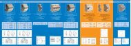
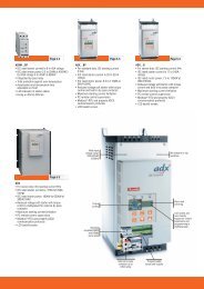
SISTEMI DI FILTRAGGIO PER FORNI AD ARCO - BATTERIE DI RIFASAMENTO IN ALTA TENSIONE<br />
FILTERING SYSTEMS FOR ARC FURNACES - H. V. POWER FACTOR CORRECTION SYSTEM<br />
2 x 19,5 MVAr - 22,7 kV - 3rd - 4th harmonics<br />
82.2 MVAr - 170 kV - 50 Hz<br />
2
I N D I C E<br />
I N D E X<br />
Generalità sul <strong>rifasamento</strong><br />
Condens<strong>at</strong>ori per <strong>rifasamento</strong><br />
Banchi di <strong>condens<strong>at</strong>ori</strong><br />
Protezione dei banchi<br />
<strong>condens<strong>at</strong>ori</strong><br />
Rifasamento dei carichi<br />
distorcenti<br />
Quadri di <strong>rifasamento</strong><br />
in media tensione<br />
Filtri armonici in pr<strong>at</strong>ica<br />
Order inform<strong>at</strong>ion<br />
4<br />
5<br />
15<br />
19<br />
22<br />
25<br />
31<br />
34<br />
General inform<strong>at</strong>ion on power<br />
factor correction<br />
Capacitors for power factor<br />
correction<br />
Capacitor banks<br />
Capacitor bank protection<br />
Power factor correction of<br />
distortion loads<br />
Medium voltage PFC panels<br />
Applic<strong>at</strong>ion example<br />
Order inform<strong>at</strong>ion<br />
3
1. Generalità sul<br />
<strong>rifasamento</strong><br />
1. General inform<strong>at</strong>ion on<br />
power factor correction<br />
Lo scopo del Rifasamento è quello di fornire localmente la<br />
potenza re<strong>at</strong>tiva necessaria al funzionamento dei carichi<br />
induttivi, aumentando il f<strong>at</strong>tore di potenza e riducendo<br />
quindi –a parità di potenza <strong>at</strong>tiva richiesta- la corrente nella<br />
rete a monte del <strong>rifasamento</strong>. Oltre ai vantaggi tecnici ed<br />
economici risultanti da un più razionale dimensionamento<br />
di trasform<strong>at</strong>ori, interruttori e linee, il <strong>rifasamento</strong> garantisce<br />
un notevole risparmio sui costi dell’energia.<br />
L’esercizio degli impianti con un basso f<strong>at</strong>tore di potenza,<br />
inf<strong>at</strong>ti, obbligherebbe il distributore dell’energia elettrica<br />
a sovra-dimensionare i propri impianti per far fronte alla<br />
maggiore potenza apparente, con conseguente aumento<br />
dei costi. Per questo motivo tutti i distributori di energia<br />
elettrica penalizzano i prelievi di energia con basso f<strong>at</strong>tore<br />
di potenza, imponendo penali economiche rilevanti sui<br />
consumi di energia re<strong>at</strong>tiva eccedenti quella corrispondente<br />
ad un f<strong>at</strong>tore di potenza minimo (generalmente pari a cos ϕ<br />
= 0,9). L’ammontare delle penali dipende dall’entità dello<br />
scostamento del cos ϕ da quello minimo, dal livello di<br />
tensione di fornitura e dal piano tariffario.<br />
Principali vantaggi di un corretto <strong>rifasamento</strong><br />
• Eliminazione delle penali per basso cos ϕ imposte dal<br />
distributore di energia elettrica.<br />
• Migliore utilizzazione delle macchine elettriche e delle<br />
condutture: a parità di potenza <strong>at</strong>tiva il <strong>rifasamento</strong><br />
riduce la potenza apparente e quindi la corrente che<br />
transita nelle sezioni di impianto a monte del <strong>rifasamento</strong>,<br />
permettendo di dimensionare l’impianto per valori<br />
inferiori di potenza apparente e corrente.<br />
• Riduzione delle perdite: riducendo la corrente che<br />
transita nelle condutture (cavi, ma anche interruttori,<br />
ecc.) si riducono notevolmente le perdite, che dipendono<br />
dal quadr<strong>at</strong>o della corrente. Le perdite di potenza, oltre<br />
a rappresentare uno spreco di energia, generano calore e<br />
determinano una maggiore temper<strong>at</strong>ura di esercizio delle<br />
condutture. Riducendo le perdite le condutture vengono<br />
esercite a temper<strong>at</strong>ure inferiori, con grandi vantaggi per<br />
quanto riguarda la dur<strong>at</strong>a di vita di tutti i loro componenti.<br />
• Minore caduta di tensione: la caduta di tensione lungo<br />
una linea dipende dalla corrente sulla linea stessa e<br />
quindi – sempre a parità di potenza <strong>at</strong>tiva – sarà tanto<br />
minore quanto più alto sarà il f<strong>at</strong>tore di potenza.<br />
The objective of Power Factor Correction is to supply the<br />
reactive power necessary to make inductive loads work by<br />
increasing the power factor and thus reducing the current<br />
in the network. Power factor correction produces technical<br />
and economical advantages resulting from a more r<strong>at</strong>ional<br />
sizing of the transformers, switches and lines, as well as<br />
guaranteeing an enormous reduction of energy costs.<br />
The functioning of the power supply system with a low power<br />
factor obliges the utility company to overload its systems in<br />
order to face the higher apparent power needs and so r<strong>at</strong>e<br />
increases become unavoidable. For this reason, all utility<br />
companies penalize low power factor energy consumption,<br />
imposing high economical penalties on reactive energy<br />
consumption th<strong>at</strong> exceeds the energy corresponding to a<br />
minimum power factor (generally equal to cos ϕ = 0,9). The<br />
total penalty value depends on how much the cos ϕ shifts<br />
from the minimum value, the supply voltage and the price<br />
list.<br />
Main advantages deriving from correct power factor correction<br />
• Elimin<strong>at</strong>ion of penalties due to low cos ϕ imposed by the<br />
utility company.<br />
• Better use of electrical machines and power lines: the<br />
power factor correction reduces the apparent power<br />
and thus the current th<strong>at</strong> passes in the system sections,<br />
allowing to size the system with inferior values of apparent<br />
power and current.<br />
• Loss reduction: losses, th<strong>at</strong> depend on the square of the<br />
energy, are drastically reduced by decreasing the current<br />
th<strong>at</strong> passes in the power lines (cables, switches, etc.).<br />
Power losses, besides representing a waste of energy,<br />
gener<strong>at</strong>e he<strong>at</strong> and cause an increase in the oper<strong>at</strong>ing<br />
temper<strong>at</strong>ure of the power lines. Consequently, power lines<br />
work <strong>at</strong> lower temper<strong>at</strong>ures, power losses are reduced<br />
and enormous advantages are obtained in terms of the<br />
lifespan of all components.<br />
• Minor voltage drop: voltage drops along the line depend<br />
on the line current. The higher the power factor, the lower<br />
the voltage drops.<br />
4
2. Condens<strong>at</strong>ori<br />
per <strong>rifasamento</strong><br />
2. Capacitors for power<br />
factor correction<br />
2.1. INTRODUZIONE<br />
La serie di <strong>condens<strong>at</strong>ori</strong> che la DUCATI presenta è il risult<strong>at</strong>o<br />
di ricerche approfondite sui dielettrici, sugli oli di impregnazione,<br />
sul processo produttivo. I <strong>condens<strong>at</strong>ori</strong> normalizz<strong>at</strong>i<br />
sono car<strong>at</strong>terizz<strong>at</strong>i da affidabilità elev<strong>at</strong>issima e lunga dur<strong>at</strong>a<br />
di vita. I m<strong>at</strong>eriali, allo st<strong>at</strong>o <strong>at</strong>tuale delle conoscenze, sono<br />
totalmente comp<strong>at</strong>ibili con l’ambiente.<br />
Oltre ai <strong>condens<strong>at</strong>ori</strong> possono essere forniti tutti gli accessori<br />
occorrenti per la realizzazione dei banchi completi e dei<br />
<strong>sistemi</strong> di filtraggio armoniche.<br />
2.1. INTRODUCTION<br />
The series of <strong>capacitors</strong> presented by DUCATI is the result<br />
of in-depth research on dielectrics, impregn<strong>at</strong>ing oils and<br />
production processes. The normalized <strong>capacitors</strong> are<br />
characterized by a very high degree of reliability and long<br />
life. Current knowledge confirms th<strong>at</strong> the m<strong>at</strong>erials used are<br />
totally comp<strong>at</strong>ible with the environment.<br />
In addition to the <strong>capacitors</strong>, all accessories necessary for<br />
the construction of complete banks and harmonic filtering<br />
systems can be supplied.<br />
2.2. CARATTERISTICHE COSTRUTTIVE<br />
DELLE UNITÀ<br />
Il condens<strong>at</strong>ore è composto da numerosi elementi capacitivi,<br />
i quali sono colleg<strong>at</strong>i in serie e parallelo al fine di realizzare<br />
la tensione e la potenza nominale.<br />
Il Dielettrico è costituito da più str<strong>at</strong>i di film di polipropilene<br />
con superficie rugosa, compresi fra le arm<strong>at</strong>ure di alluminio.<br />
Gli Elettrodi sono costituiti da un sottile foglio di alluminio<br />
purissimo.<br />
L’ Impregnante è un olio sintetico, biodegradabile, non tossico,<br />
con contenuto di cloro < 5 PPM. Il Contenitore è realizz<strong>at</strong>o<br />
in lamiera di acciaio pieg<strong>at</strong>a e sald<strong>at</strong>a elettricamente, è<br />
particolarmente robusto e in grado di sopportare le normali<br />
sollecitazioni determin<strong>at</strong>e dai guasti. Esso è completamente<br />
pieno, la perfetta ermeticità del contenitore è una valida<br />
garanzia contro la degradazione dei m<strong>at</strong>eriali, assicurando<br />
una lunga vita al condens<strong>at</strong>ore.<br />
L’elasticità delle superfici maggiori del contenitore è tale da<br />
compensare le variazioni di volume del liquido impregnante<br />
nella gamma delle temper<strong>at</strong>ure previste nel funzionamento,<br />
contenendo entro limiti modesti la variazione di pressione interna.<br />
Il contenitore è inoltre dot<strong>at</strong>o di due maniglie da utilizzare per<br />
il sollevamento ed il fissaggio del condens<strong>at</strong>ore sul telaio di<br />
installazione. A richiesta, i <strong>condens<strong>at</strong>ori</strong> destin<strong>at</strong>i ad essere<br />
us<strong>at</strong>i in ambienti particolarmente aggressivi, possono essere<br />
forniti con contenitore in acciaio inox.<br />
Tr<strong>at</strong>tamento superficiale<br />
Al fine di garantire una perfetta efficienza della protezione<br />
contro la ruggine, anche in ambienti fortemente aggressivi,<br />
sulla superficie del contenitore si effettua la sabbi<strong>at</strong>ura del<br />
metallo e successivamente la vernici<strong>at</strong>ura con più str<strong>at</strong>i di<br />
vernice unicomponente.<br />
Terminali<br />
I terminali del condens<strong>at</strong>ore sono posti su passanti in<br />
porcellana, vetrific<strong>at</strong>a per una perfetta resistenza agli agenti<br />
<strong>at</strong>mosferici. Il passante in porcellana è metallizz<strong>at</strong>o sia<br />
per il fissaggio al coperchio del condens<strong>at</strong>ore, che per il<br />
fissaggio del terminale a vite di collegamento. I passanti sono<br />
perfettamente ermetici e particolarmente robusti.<br />
2.2. MANUFACTURING CHARACTERISTICS<br />
OF THE UNIT<br />
The capacitor is composed of many capacitive elements th<strong>at</strong><br />
are connected in series and in parallel to obtain the r<strong>at</strong>ed<br />
voltage and power.<br />
The Dielectric is composed of several layers of polypropylene<br />
film with rough surface, held between aluminum pl<strong>at</strong>es.<br />
Electrodes are made of a thin sheet of pure aluminum.<br />
Impregn<strong>at</strong>ing substance is a non-toxic, biodegradable,<br />
synthetic oil with a chlorine content < 5 PPM. The sturdy<br />
capacitor case, made of electrically welded sheet steel,<br />
is able to withstand the normal stress produced by<br />
breakdowns. It is completely full and the perfect sealing of<br />
the case avoids m<strong>at</strong>erial deterior<strong>at</strong>ion, thus ensuring long<br />
life to the capacitor.<br />
The elasticity of the larger surfaces of the case compens<strong>at</strong>es<br />
for the vari<strong>at</strong>ions in the volume of the impregn<strong>at</strong>ing liquid in<br />
the oper<strong>at</strong>ing temper<strong>at</strong>ure range and so keeps the vari<strong>at</strong>ions<br />
in the internal pressure to a minimum.<br />
The case is equipped with two handles necessary for the<br />
lifting and fixing of the capacitor on the install<strong>at</strong>ion frame.<br />
Capacitors destined for use in particularly aggressive<br />
environments can be supplied with a stainless steel case.<br />
Surface tre<strong>at</strong>ment<br />
The case surface is sandblasted and then painted with several<br />
layers of single-component paint in order to efficiently avoid<br />
rust, even in highly aggressive environments.<br />
Terminals<br />
The capacitor terminals are loc<strong>at</strong>ed on brown porcelain<br />
feedthroughs, glazed to guarantee perfect resistance to<br />
<strong>at</strong>mospheric elements. The porcelain bushings are metalized<br />
for both fastening to the capacitor cover and for fixing to<br />
the screw terminal connections. The bushings are perfectly<br />
sealed and particularly sturdy.<br />
5
Dispositivi di scarica<br />
In conformità alle norm<strong>at</strong>ive i <strong>condens<strong>at</strong>ori</strong> sono corred<strong>at</strong>i<br />
internamente di resistori di scarica <strong>at</strong>ti a ridurre la tensione<br />
residua a meno di 75 V entro 10 minuti dalla disinserzione.<br />
Discharge devices<br />
In full compliance with Standards, the <strong>capacitors</strong> are internally<br />
fitted with discharge resistors to reduce the residual voltage<br />
to less than 75 V within 10 minutes from shutdown.<br />
2.3. COMPATIBILITÀ CON L’AMBIENTE<br />
DEI MATERIALI IMPIEGATI<br />
L’impregnante impieg<strong>at</strong>o è il risult<strong>at</strong>o di lunghe ricerche e<br />
prove sperimentali eseguite su tutti gli oli isolanti per uso<br />
dielettrico disponibili al momento; esso rappresenta sicuramente<br />
la migliore soluzione che tenga conto delle esigenze di<br />
rispetto dell’ambiente e di car<strong>at</strong>teristiche dielettriche elev<strong>at</strong>e.<br />
Tali liquidi sono classific<strong>at</strong>i come non pericolosi e non se<br />
ne richiede di norma la registrazione. Tuttavia la detenzione<br />
dei <strong>condens<strong>at</strong>ori</strong> e la loro distruzione deve essere comunque<br />
effettu<strong>at</strong>a nel rispetto delle norme e regolamenti vigenti nel<br />
luogo di utilizzo.<br />
2.3. ENVIRONMENTAL COMPATIBILITY<br />
OF THE MATERIALS USED<br />
The impregn<strong>at</strong>ing agent used is the result of long and<br />
continuous research and experimental tests on all insul<strong>at</strong>ing<br />
oils for dielectric use currently available. It offers the best<br />
solution able to both protect the environment as well as to<br />
handle the high dielectric characteristics.<br />
These liquids are not considered dangerous and their<br />
registr<strong>at</strong>ion is normally not required. However, the storage<br />
and destruction of the <strong>capacitors</strong> must be carried-out in<br />
accordance with the regul<strong>at</strong>ions in force in the place of use.<br />
2.4. CARATTERISTICHE ELETTRICHE<br />
Potenze normalizz<strong>at</strong>e<br />
(temper<strong>at</strong>ura 20 °C)<br />
: 50 ÷ 800 kVAR<br />
Tensioni nominali standardizz<strong>at</strong>e : tab. 4 e 5<br />
Frequenza nominale<br />
: 50 Hz (60 Hz a richiesta)<br />
Tolleranza sulla capacità<br />
<strong>condens<strong>at</strong>ori</strong> : -5% +10%<br />
banchi oltre 10 Mvar : 0% +10%<br />
banchi oltre 30 Mvar : 0% +5%<br />
Perdite: (a Vn-20 °C dopo stabilizzazione) : Dielettrico tutto-film<br />
< 0,01% (< 0,1 w / kVAR )<br />
Dispositivi di scarica interni<br />
(tensione residua)<br />
: 75 V dopo 10 minuti<br />
: 50 V dopo 5 minuti<br />
Norme : IEC 871 - 1 e 2<br />
CEI 33 - 7 fas. 1668<br />
BS - VDE - NEMA<br />
ed altre importanti<br />
norme<br />
Stabilizzazione<br />
tensione e frequenza nominale<br />
e temper<strong>at</strong>ure ambiente di 45 °C<br />
: 100 h<br />
2.4. ELECTRICAL CHARACTERISTICS<br />
Normalized power<br />
(temper<strong>at</strong>ure 20 °C)<br />
: 50 ÷ 800 kVAR<br />
Standardized r<strong>at</strong>ed voltage : Table 4 and 5<br />
R<strong>at</strong>ed frequency<br />
: 50 Hz (60 Hz on request)<br />
Tolerance on the capacitance<br />
<strong>capacitors</strong> : -5% + 10%<br />
banks over 10 Mvar : 0% + 10%<br />
banks over 30 Mvar : 0% + 5%<br />
Losses: (<strong>at</strong> Vn 20 °C after stabilizing) : All-film dielectric<br />
< 0,01% (< 0,1 w / kVAR )<br />
Internal discharge devices<br />
(residual voltage)<br />
: 75 V after 10 min.<br />
: 50 V after 5 min.<br />
Standards : IEC 871 - 1 and 2<br />
CEI 33 - 7 fas. 1668<br />
BS - VDE - NEMA<br />
and other relevant<br />
Standards<br />
Stabiliz<strong>at</strong>ion<br />
r<strong>at</strong>ed voltage and frequency<br />
and ambient temper<strong>at</strong>ure of 45 °C<br />
: 100 h<br />
Figura 1: Capacità in funzione della temper<strong>at</strong>ura.<br />
Picture 1: Capacitance vs. temper<strong>at</strong>ure.<br />
Figura 2: Dielettrico tutto film, angolo di perdita in funzione della<br />
temper<strong>at</strong>ura.<br />
Picture 2: All film dielectric, loss angle vs. temper<strong>at</strong>ure.<br />
6
2.5. CONDIZIONI DI SERVIZIO E DI USO<br />
CORRETTO<br />
Servizio<br />
Condizioni ambientali<br />
: installazione per<br />
esterno<br />
Classe di temper<strong>at</strong>ure (–25/B) : –25 °C + 45 °C<br />
(Tab. 1)<br />
Classe di temper<strong>at</strong>ura (–25/D) : su richiesta<br />
Altitudine massima<br />
: 1.000 m (s.l.m.)<br />
Sovr<strong>at</strong>ensioni ammesse a<br />
frequenza <strong>industriale</strong> : come da Tabella 2<br />
Sovrantensione per transitorio<br />
di inserzione<br />
: ≤ 2 2 Vn<br />
Max valore di cresta del<br />
transitorio di corrente<br />
: 100 In<br />
Massima dur<strong>at</strong>a del transitorio : 0,5 periodi<br />
Massimo numero di inserzioni : 1.000 all’anno<br />
Massima sovracorrente ammessa<br />
per la presenza contemporanea<br />
di sovr<strong>at</strong>ensione e di armoniche : I max ≤ 1,3 In<br />
(per C = Cn)<br />
2.5. SERVICE CONDITIONS AND<br />
CORRECT USE<br />
Service<br />
Enviromental conditions<br />
: outdoor install<strong>at</strong>ion<br />
Temper<strong>at</strong>ure c<strong>at</strong>egory (–25/B) : –25 °C + 45 °C<br />
(Table 1)<br />
Temper<strong>at</strong>ure c<strong>at</strong>egory (–25/D) : on request<br />
Maximum altitude<br />
: 1.000 m (a.s.l.)<br />
Overvoltage allowed <strong>at</strong><br />
r<strong>at</strong>ed frequency : as in Table 2<br />
Switching overvoltages<br />
Maximum peak value of<br />
current transient<br />
Maximum dur<strong>at</strong>ion of transient<br />
Maximum switching oper<strong>at</strong>ions<br />
Maximum overcurrent allowed<br />
for the simultaneous presence<br />
of overvoltage and harmonics<br />
: ≤ 2 2 Vn<br />
: 100 In<br />
: 0.5 periods<br />
: 1,000 per year<br />
: I max ≤ 1.3 In<br />
(per C = Cn)<br />
Tabella 1<br />
Massimi valori di temper<strong>at</strong>ura per le diverse classi.<br />
(I valori possono essere rilev<strong>at</strong>i dalle tabelle meteorologiche di temper<strong>at</strong>ura della località di installazione).<br />
Table 1<br />
Maximum temper<strong>at</strong>ure values for the different c<strong>at</strong>egories.<br />
(The values can be found in the meteorological temper<strong>at</strong>ure values covering the install<strong>at</strong>ion site).<br />
Massima temper<strong>at</strong>ura dell’aria ambiente (°C) / Maximum ambient air temper<strong>at</strong>ure (°C)<br />
Classe<br />
di temp. Massimo Massimo valore della temper<strong>at</strong>ura media / Highest mean over any period<br />
Temper<strong>at</strong>ure assoluto<br />
c<strong>at</strong>egory Upper limit in un giorno / in one day in un anno / in one year<br />
A 40° 30° 20°<br />
B 45° 35° 25°<br />
C 50° 40° 30°<br />
D 55° 45° 35°<br />
Qualora il calore prodotto dai <strong>condens<strong>at</strong>ori</strong> influenzi la temper<strong>at</strong>ura ambiente, è ammesso un aumento di 5 °C dei valori summenzion<strong>at</strong>i (Es:<br />
installazione all’interno).<br />
If the <strong>capacitors</strong> influence the ambient air temper<strong>at</strong>ure the above values can be increased by 5 °C (Ex.: internal install<strong>at</strong>ion).<br />
Tabella 2<br />
Ampiezza delle sovr<strong>at</strong>ensioni massime ammesse.<br />
Table 2<br />
Maximum overvoltage allowed.<br />
F<strong>at</strong>tore di sovr<strong>at</strong>ensione Massima dur<strong>at</strong>a Causa / Cause<br />
Overvoltage factor<br />
Maximum dur<strong>at</strong>ion<br />
1,10 Vn 12 ore al giorno - 12 h per day<br />
1.15 Vn 30' al giorno - 30' per day<br />
1,20 Vn* 5’<br />
1,30 Vn* 1’<br />
Fluttuazioni della tensione di rete<br />
Fluctu<strong>at</strong>ion in network voltage<br />
Aumento di tensione nei momenti di basso carico<br />
Voltage increase in periods of low load<br />
* Non più di 200 volte nella vita di un condens<strong>at</strong>ore.<br />
* Not more than 200 times in the life of the capacitor.<br />
7
Riduzione della vita per sovr<strong>at</strong>ensioni permanenti<br />
Le sovr<strong>at</strong>ensioni di lunga dur<strong>at</strong>a, indic<strong>at</strong>e sulla tabella 2, devono<br />
essere contenute entro i limiti di tempo indic<strong>at</strong>i; diversamente<br />
costituiscono una sollecitazione pericolosa per<br />
il dielettrico.<br />
Nella scelta della tensione nominale del condens<strong>at</strong>ore occorre<br />
tenere presente che le sovr<strong>at</strong>ensioni permanenti danno<br />
luogo ad una diminuzione della vita del condens<strong>at</strong>ore.<br />
Per questo motivo è opportuno tenere conto, ad esempio,<br />
dell’aumento che subirà la tensione di rete con l’installazione<br />
dei <strong>condens<strong>at</strong>ori</strong>, inoltre negli impianti dove siano presenti<br />
armoniche queste si traducono in aumenti della tensione di<br />
lavoro dei <strong>condens<strong>at</strong>ori</strong>, in particolare qualora si verifichino<br />
risonanze. Si dovrà quindi valutare in ogni situazione il valore<br />
più ad<strong>at</strong>to di tensione nominale per il condens<strong>at</strong>ore.<br />
La curva di figura 3 esprime la diminuzione della vita di un<br />
condens<strong>at</strong>ore, in funzione del coefficiente di sovr<strong>at</strong>ensione<br />
permanente.<br />
Analogamente condizioni di servizio che comportino temper<strong>at</strong>ure<br />
del dielettrico più elev<strong>at</strong>e del previsto, portano ad una<br />
diminuzione della vita del condens<strong>at</strong>ore, secondo una legge<br />
simile a quella di figura 4.<br />
La temper<strong>at</strong>ura assunta dal condens<strong>at</strong>ore è influenz<strong>at</strong>a da<br />
molteplici f<strong>at</strong>tori oltre che dalla tensione di lavoro e dalla<br />
temper<strong>at</strong>ura ambiente, ad esempio dalle condizioni di dissipazione<br />
del calore da parte del condens<strong>at</strong>ore, dall’influenza<br />
del condens<strong>at</strong>ore sulla temper<strong>at</strong>ura dell’ambiente di installazione,<br />
dalla presenza di armoniche in rete, ecc.<br />
Life reduction due to permanent overvoltages<br />
The long-time overvoltages, shown in Table 2, must remain<br />
within the indic<strong>at</strong>ed limits of dur<strong>at</strong>ion, otherwise they<br />
represent a dangerous stress for the dielectric.<br />
Permanent overvoltages shorten the capacitor’s life and this<br />
must be considered when choosing the r<strong>at</strong>ed voltage of<br />
the capacitor. For this reason, it is important to consider, for<br />
example, the increase in voltage th<strong>at</strong> the network will undergo<br />
with the install<strong>at</strong>ion of the <strong>capacitors</strong>. Moreover, the presence<br />
of harmonics in systems increases the working voltage of the<br />
<strong>capacitors</strong>, particularly when there are resonances. The most<br />
suitable r<strong>at</strong>ed voltage for the capacitor must be evalu<strong>at</strong>ed in<br />
every situ<strong>at</strong>ion.<br />
The curve in Figure 3 shows the decrease in capacitor’s life<br />
according to the coefficient of permanent voltage.<br />
In the same way, oper<strong>at</strong>ing conditions th<strong>at</strong> require higher than<br />
expected temper<strong>at</strong>ures of the dielectric gener<strong>at</strong>e a decrease<br />
of the capacitor’s life, according to a law similar to the one<br />
in Figure 4.<br />
The temper<strong>at</strong>ure assumed by the capacitor is influenced by<br />
many different factors, such as working voltage and ambient<br />
temper<strong>at</strong>ure, the capacitor’s he<strong>at</strong> dissip<strong>at</strong>ion conditions, the<br />
influence of the capacitor on the ambient temper<strong>at</strong>ure <strong>at</strong> the<br />
install<strong>at</strong>ion site, the presence of harmonics in the network,<br />
etc.<br />
Figura 3 / Picture 3<br />
Figura 4 / Picture 4<br />
Sicurezza<br />
Anche se remota, esiste sempre la possibilità che il condens<strong>at</strong>ore<br />
esploda, quando andrà in cortocircuito alla fine della sua<br />
vita, e ciò pur avendolo protetto nel miglior modo possibile.<br />
In particolare questo può avvenire con maggiore probabilità<br />
nei <strong>condens<strong>at</strong>ori</strong> trifase, la cui protezione contro i cortocircuiti<br />
richiede margini notevoli, poiché ci si deve cautelare contro i<br />
sovraccarichi permanenti e i transitori di inserzione.<br />
Safety<br />
There is a remote possibility of the capacitor exploding when<br />
it short circuits <strong>at</strong> the end of its lifespan, even if it has been<br />
protected in the best way possible. This situ<strong>at</strong>ion is more<br />
probable with three-phase <strong>capacitors</strong> where the short circuit<br />
protection requires significant margins as the safeguarding<br />
against permanent and switching transitory overloads is<br />
necessary.<br />
8
È quindi necessario che i <strong>condens<strong>at</strong>ori</strong> siano sempre segreg<strong>at</strong>i<br />
in ambiente idoneo, in modo che nell’eventualità di esplosione<br />
sia esclusa ogni possibilità di danno alle persone e cose.<br />
Questo rischio è inesistente per i <strong>condens<strong>at</strong>ori</strong> monofase dei<br />
banchi protetti con protezione a squilibrio di corrente, dove<br />
l’evento potrebbe verificarsi solo in caso di guasto a massa<br />
del condens<strong>at</strong>ore, conseguente ad esempio alla fuoruscita<br />
totale dell’olio di impregnazione.<br />
Therefore, <strong>capacitors</strong> must always be kept in suitable<br />
environments in order to elimin<strong>at</strong>e the risk of damage to<br />
people or things in case of explosions. This risk does not exist<br />
for single-phase <strong>capacitors</strong> in banks protected by current<br />
unbalance protection, where the event could arise only in<br />
the case of a breakdown of the capacitor earth due to, for<br />
example, the total leakage of impregn<strong>at</strong>ing oil.<br />
2.6. NORME DI RIFERIMENTO E PROVE<br />
I <strong>condens<strong>at</strong>ori</strong> della presente serie sono conformi alle<br />
raccomandazioni dell’Intern<strong>at</strong>ional Electrical Commission<br />
IEC - 871-1 e 2 ed. 2004. Essi soddisfano altresì le Norme<br />
Nazionali del Comit<strong>at</strong>o Elettrotecnico Italiano (CEI 33 - 7 -<br />
fascicolo 1668) ed a quelle dei principali paesi del mondo.<br />
Prove individuali<br />
– Misura della capacità (CEI - art. 7)<br />
– Misura della tangente dell’angolo di perdita (CEI - art. 8)<br />
– Prova di tensione fra i terminali a secco, eseguita alla<br />
tensione di 4,3 Vn in. c.c., oppure a 2,15 Vn in c.a. per 10<br />
secondi (CEI - art. 9).<br />
– Prova di tensione verso la cassa a secco (CEI - art. 10).<br />
– Controllo delle resistenze di scarica (CEI - art. 11).<br />
– Verifica dell’ermeticità della cassa (CEI - art. 12).<br />
Prove di tipo<br />
– Misura a temper<strong>at</strong>ura elev<strong>at</strong>a della capacità e della<br />
tangente dell’angolo di perdita (CEI - art. 14).<br />
– Prova di tensione in corrente altern<strong>at</strong>a tra i terminali e il<br />
contenitore (CEI - art. 15).<br />
– Prova di tenuta con tensione ad impulsi (CEI - art. 16).<br />
– Verifica del rivestimento protettivo esterno della cassa:<br />
• (verifica dello spessore del rivestimento protettivo e<br />
verifica dell’aderenza del rivestimento protettivo).<br />
Prove di qualificazione eseguite su modelli durante<br />
l’omologazione del tipo<br />
– Prova di stabilità termica (CEI - art. 13)<br />
– Prova di scarica in cortocircuito (CEI - art. 17)<br />
– Prove di invecchiamento (CEI 33-7 all. 2):<br />
• prova di resistenza alle sovr<strong>at</strong>ensioni (art. 4.4);<br />
• prova di sovraccarico (art. 4.5).<br />
Qualità<br />
Il SISTEMA QUALITÀ della Duc<strong>at</strong>i Energia spa, sezione<br />
<strong>condens<strong>at</strong>ori</strong>, descritti nel Manuale della Qualità è st<strong>at</strong>o<br />
fra i primi in Italia ad essere approv<strong>at</strong>o dal BSI secondo le<br />
procedure ISO 9002 (EN 29002): Certific<strong>at</strong>o di Registrazione<br />
N. FM22004.<br />
Recentemente è st<strong>at</strong>o approv<strong>at</strong>o dal CSQ secondo le norme<br />
ISO 9001. I <strong>condens<strong>at</strong>ori</strong> di Alta Tensione sono conformi<br />
alle Direttive comunitarie 89/336 e 92/31 “Comp<strong>at</strong>ibilità<br />
Elettromagnetica”.<br />
La Duc<strong>at</strong>i impiega processi produttivi fortemente integr<strong>at</strong>i,<br />
macchine e tecnologie completamente nuove e innov<strong>at</strong>ive,<br />
metodologie del controllo del processo produttivo bas<strong>at</strong>e<br />
su accur<strong>at</strong>e specifiche e sulla responsabilizzazione degli<br />
oper<strong>at</strong>ori a tutti i livelli.<br />
2.6. REFERENCE STANDARDS AND TESTS<br />
The <strong>capacitors</strong> of this series comply with the recommend<strong>at</strong>ions<br />
of the Intern<strong>at</strong>ional Electrotechnical Commission IEC - 871-<br />
1 and 2 Ed. 2004. as well as the Italian Electrotechnical<br />
Committee Standards (IEC 33 - 7 – pamphlet 1668) and<br />
those of most major n<strong>at</strong>ions.<br />
Routine tests<br />
– Capacitance measurement (IEC – Clause 7).<br />
– Measurement of the loss angle tangent (IEC - Clause 8).<br />
– Voltage test between terminals carried-out <strong>at</strong> 4.3 Vn in DC<br />
or <strong>at</strong> 2.15 Vn in AC for 10 seconds (IEC Clause 9).<br />
– Voltage dry test between terminals and case (IEC - Clause<br />
10).<br />
– Internal discharge device test (IEC - Clause 11).<br />
– Sealing test (IEC - Clause 12).<br />
Type tests<br />
– Measurement of loss angle tangent and capacitance <strong>at</strong><br />
high temper<strong>at</strong>ure (IEC - Clause 14).<br />
– AC voltage test between terminals and case (IEC - Clause 15).<br />
– Lightning impulse voltage test (IEC - Clause 16).<br />
– Case protective co<strong>at</strong>ing test:<br />
• (check of the thickness of the protective co<strong>at</strong>ing and its<br />
adhesion).<br />
Design tests on models during the homolog<strong>at</strong>ion of<br />
types<br />
– Thermal stability test (IEC - Clause 13).<br />
– Short circuit discharge test (IEC - Clause 17).<br />
– Endurance tests (IEC 33-7 Annex 2):<br />
• overvoltage test (Clause 4.4);<br />
• overload run (Clause 4.5).<br />
Quality<br />
The QUALITY SYSTEM of Duc<strong>at</strong>i Energia SpA, capacitor<br />
division, as described in the Quality Manual, was one of the<br />
first in Italy to be approved by BSI according to ISO 9002 (EN<br />
29002) procedures: Certific<strong>at</strong>e of Registr<strong>at</strong>ion N. FM22004.<br />
Recently, it has been approved by CSQ according to the ISO<br />
9001 requirements. The High Voltage <strong>capacitors</strong> comply with<br />
the Electromagnetic Comp<strong>at</strong>ibility Directives 89/336 EEC<br />
and 92/31 EEC.<br />
Duc<strong>at</strong>i Energia uses fully integr<strong>at</strong>ed processes, completely<br />
new and innov<strong>at</strong>ive machines and technologies, production<br />
process control methodologies based on accur<strong>at</strong>e<br />
specific<strong>at</strong>ions and oper<strong>at</strong>or responsibility.<br />
9
2.7. CONDENSATORI MONOFASE<br />
2.7. SINGLE-PHASE CAPACITORS<br />
Generalità<br />
Sono espressamente progett<strong>at</strong>i per la costruzione di banchi<br />
trifase destin<strong>at</strong>i al <strong>rifasamento</strong> o alla realizzazione di <strong>filtri</strong> di<br />
armonica.<br />
Costruttivamente possono essere classific<strong>at</strong>i in base a:<br />
– presenza/assenza dei fusibili interni;<br />
– al numero dei terminali isol<strong>at</strong>i (1 o 2);<br />
– m<strong>at</strong>eriale del contenitore (acciaio magnetico / amagnetico);<br />
– classe d’isolamento.<br />
Esecuzione normale vs fusibili interni<br />
I <strong>condens<strong>at</strong>ori</strong> senza fusibili interni sono realizz<strong>at</strong>i da<br />
elementi capacitivi connessi in serie e parallelo.<br />
Il guasto di un elemento capacitivo determina un cortocircuito<br />
della sezione-serie associ<strong>at</strong>a a quella unità. Ciò produce un<br />
aumento della corrente che la <strong>at</strong>traversa e un aumento della<br />
tensione sugli elementi rimanenti di quella unità capacitiva e<br />
sulle altre unità nella fila associ<strong>at</strong>a. E’ buona norma sostituire<br />
l’unita guasta fin dal rilevamento del primo guasto.<br />
Nei <strong>condens<strong>at</strong>ori</strong> con fusibili interni, tutti gli elementi<br />
capacitivi costituenti l’unità hanno in serie un fusibile.<br />
Se uno di questi elementi si perfora è autom<strong>at</strong>icamente<br />
scolleg<strong>at</strong>o dalla fusione del proprio fusibile senza che<br />
l’unità sia interess<strong>at</strong>a dal corto circuito. Dopo l’eliminazione<br />
dell’elemento guasto, l’unità resta in servizio e continuerà<br />
a funzionare ad una potenza re<strong>at</strong>tiva ridotta di qualche<br />
percento, ciò in conseguenza del grande numero di elementi<br />
costituenti l’unità. Ovviamente non è necessario rimuovere<br />
tale unità dal servizio in quanto la capacità rientra di norma<br />
nei limiti della tolleranza e le altre unità del banco non<br />
subiscono influenze apprezzabili.<br />
Non è possibile realizzare tutta la gamma di <strong>condens<strong>at</strong>ori</strong><br />
con fusibili interni questo è dovuto principalmente ad alcune<br />
limitazioni, di ordine costruttivo ed economico,<br />
Nel grafico x sono visualizz<strong>at</strong>e le combinazioni potenza/<br />
tensione realizzabili con <strong>condens<strong>at</strong>ori</strong> monofase a fusibili<br />
interni.<br />
Indic<strong>at</strong>ivamente la gamma realizzabile è dett<strong>at</strong>a dai seguenti<br />
criteri<br />
– potenza > 300 kVAR (per tensioni più basse)<br />
– tensione < 12 kV (per potenze più alte)<br />
Figura 5: Configurazioni kVAr/kV per le quali è possibile l'esecuzione<br />
con fusibili interni. Condens<strong>at</strong>ori con car<strong>at</strong>teristiche al di fuori dell'area<br />
color<strong>at</strong>a possono essere prodotti solo previa verifica tecnica.<br />
Picture 5: Possible internal fuse capacitor kVAr/kV configur<strong>at</strong>ions are in<br />
blue area. Capacitors with characteristics outside the blue area can be<br />
produced only after technical approval.<br />
General inform<strong>at</strong>ion<br />
Single-phase <strong>capacitors</strong> have been specifically produced for<br />
the construction of three-phase banks for use in power factor<br />
correction or in the realiz<strong>at</strong>ion of harmonic filters.<br />
From the construction point of view, they can be classified<br />
according to the following criteria:<br />
– presence/absence of internal fuses;<br />
– number of insul<strong>at</strong>ed terminals (1 or 2);<br />
– case m<strong>at</strong>erial (magnetic / amagnetic steel);<br />
– insul<strong>at</strong>ion class.<br />
Standard version vs internal fuses<br />
Capacitors without internal fuses are composed of capacitive<br />
elements connected in series or in parallel. The breakdown of<br />
one capacitive element gener<strong>at</strong>es a short circuit of the seriessection<br />
associ<strong>at</strong>ed to the unit. This produces an increase in<br />
the circul<strong>at</strong>ing current as well as a voltage increase in the<br />
other elements of the capacitive unit and on the other units<br />
of the associ<strong>at</strong>ed line. The replacement of the faulty unit is<br />
recommended as soon as the first breakdown is detected.<br />
In <strong>capacitors</strong> with internal fuses, all capacitive elements<br />
th<strong>at</strong> form the unit have a fuse in the series. If an element is<br />
pierced, it is autom<strong>at</strong>ically unconnected from its fuse without<br />
gener<strong>at</strong>ing a short circuit in the unit. After replacing the faulty<br />
element, the unit continues to work with a reactive power<br />
reduced of only a small percentage. The unit does not have to<br />
be removed as the capacitance is normally toler<strong>at</strong>ed and the<br />
other bank units are not conditioned in a significant manner.<br />
The entire capacitor range can not be produced with internal<br />
fuses mainly due to constructive and economical constraints.<br />
The graphic X shows the power/voltage combin<strong>at</strong>ions th<strong>at</strong><br />
can be obtained with single-phase <strong>capacitors</strong> with internal<br />
fuses.<br />
The range is indic<strong>at</strong>ively produced according to the following<br />
criteria:<br />
– power > 300 kVAR (for lower voltages)<br />
– voltage < 12 kV (for higher powers)<br />
Q [kVAr]<br />
900<br />
800<br />
700<br />
600<br />
500<br />
400<br />
300<br />
200<br />
100<br />
0<br />
1 2 3 4 5 6 7 8 9 10 11 12 13 14 15<br />
Vn [kV]<br />
10
Figura 6: Condens<strong>at</strong>ori con fusibili interni.<br />
Picture 6: Capacitors with internal fuses.<br />
Figura 7: Condens<strong>at</strong>ori senza fusibili interni.<br />
Picture 7: Capacitors without internal fuses.<br />
Tab. 3: Isol<strong>at</strong>ori passanti<br />
Table 3: Bushings<br />
Livello di isolamento<br />
Highest System Voltage<br />
kV<br />
BIL<br />
kV<br />
D<br />
mm<br />
Linea di fuga<br />
Creepage distance<br />
mm<br />
12 28/75 235 300<br />
24 50/125 315 600<br />
36 70/170 430 880<br />
11
Dimensioni dei <strong>condens<strong>at</strong>ori</strong> monofase<br />
Nella tabella x viene riport<strong>at</strong>a la gamma di potenza realizzabile.<br />
Le unità a 50 Hz possono essere utilizz<strong>at</strong>e anche su reti con<br />
frequenza di 60 Hz, in tal caso le potenze di targa dovranno<br />
essere maggior<strong>at</strong>e del 20%.<br />
Frequenza nominale: 50 Hz<br />
Dimensions of single-phase <strong>capacitors</strong><br />
Table X shows the voltage range th<strong>at</strong> can be produced.<br />
The units with 50 Hz can be used also on networks with a<br />
frequency of 60 Hz. In this case, the r<strong>at</strong>ed power must be<br />
increased by 20%.<br />
R<strong>at</strong>ed frequency: 50 Hz<br />
Figura 8: Condens<strong>at</strong>ori con 2 terminali isol<strong>at</strong>i (I).<br />
Picture 8: Capacitors with 2 insul<strong>at</strong>ed terminals (I).<br />
Figura 9: Condens<strong>at</strong>ori con 1 terminale isol<strong>at</strong>o (E).<br />
Picture 9: Capacitors with 1 insul<strong>at</strong>ed terminal (E).<br />
Highest system voltage 12 kV 24 kV 36 kV<br />
kVAr A mm B mm C mm H tot. mm Weight kg H tot. mm Weight kg H tot.mm Weight kg<br />
25 125 150 100 310 13 – – – –<br />
50 160 150 100 340 14 420 16 x x<br />
67 180 150 100 360 16 440 18 x x<br />
83 200 150 100 380 18 460 20 x x<br />
100 230 150 100 410 20 490 22 605 24<br />
133 280 150 100 460 24 540 26 655 28<br />
150 300 150 100 480 26 560 28 675 30<br />
167 320 150 100 500 28 580 30 695 32<br />
200 370 150 100 550 32 630 34 745 36<br />
250 440 150 100 620 38 700 40 815 42<br />
300 515 150 230 695 44 775 46 890 48<br />
350 590 150 230 770 50 850 52 965 54<br />
400 560 175 230 740 56 820 58 935 60<br />
450 630 175 230 810 61 890 63 1010 65<br />
500 690 175 230 870 68 950 70 1070 72<br />
550 750 175 320 930 73 1010 75 1125 77<br />
600 810 175 320 990 78 1070 80 1185 82<br />
650 830 175 320 1010 83 1090 85 1210 87<br />
700 870 175 320 1050 87 1130 89 1250 91<br />
750 1000 175 360 1180 91 1260 93 1400 95<br />
800 1040 175 360 1220 99 1300 101 1450 103<br />
Tab. 4: Dimensioni, pesi e gamma della tensione. / Table 4: Dimensions, weights and voltage range.<br />
12
2.8. CONDENSATORI TRIFASE<br />
2.8. THREE-PHASE CAPACITORS<br />
Generalità<br />
I <strong>condens<strong>at</strong>ori</strong> trifase sono espressamente progett<strong>at</strong>i per il<br />
<strong>rifasamento</strong> a vuoto di trasform<strong>at</strong>ori e di grossi motori in MT.<br />
Devono essere protetti tramite fusibili HCR e devono inoltre<br />
essere segreg<strong>at</strong>i in ambienti chiusi.<br />
La Duc<strong>at</strong>i al fine di ottimizzare la standardizzazione del prodotto<br />
ha realizz<strong>at</strong>o i <strong>condens<strong>at</strong>ori</strong> per le tensioni di rete normali di<br />
3,3 kV - 5,5 kV - 6,3 kV - 11 kV. Per ciascuna di queste tensioni<br />
il dimensionamento è f<strong>at</strong>to per i valori di “Design Voltage”<br />
indic<strong>at</strong>i in tabella 5. Ad esempio un condens<strong>at</strong>ore a 6,3 kV potrà<br />
lavorare a 6,6 kV perché è dimension<strong>at</strong>o per questa tensione. La<br />
potenza resa sarà quella indic<strong>at</strong>a nella rel<strong>at</strong>iva colonna. Per reti<br />
a tensione intermedia fra quelle standard, si dovrà utilizzare la<br />
tensione superiore, con la riduzione di potenza conseguente.<br />
Per tutti la classe di isolamento è 12 kV.<br />
Le unità a 50 Hz possono essere utilizz<strong>at</strong>e anche su reti con<br />
frequenza di 60 Hz, in tal caso le potenze di targa dovranno<br />
essere maggior<strong>at</strong>e del 20%.<br />
Frequenza nominale: 50 Hz<br />
General inform<strong>at</strong>ion<br />
The three-phase <strong>capacitors</strong> have been specifically designed<br />
for power factor correction of transformers and large motors<br />
in Medium Voltage. They must be protected with HCR fuses<br />
and must be kept separ<strong>at</strong>ely in a closed environment.<br />
To optimize product standardiz<strong>at</strong>ion, Duc<strong>at</strong>i has produced<br />
<strong>capacitors</strong> for the normal network voltages of 3.3 kV - 5.5 kV -<br />
6.3 kV - 11 kV. For each of these voltages, the sizing is made for<br />
the “Design Voltage” values indic<strong>at</strong>ed in Table 5. For example,<br />
a 6.3 kV capacitor can oper<strong>at</strong>e <strong>at</strong> 6.6 kV as long as it is sized<br />
for this voltage. The power r<strong>at</strong>ed for each voltage level will<br />
be th<strong>at</strong> indic<strong>at</strong>ed in the rel<strong>at</strong>ive column. For networks with<br />
intermedi<strong>at</strong>e voltage, between the standard ones, it is necessary<br />
to use the higher voltage with the resulting reduction in power.<br />
The insul<strong>at</strong>ion class is 12 kV for all.<br />
The units with 50 Hz can be used also on networks with a<br />
frequency of 60 Hz. In this case, the r<strong>at</strong>ed power must be<br />
increased by 20%.<br />
R<strong>at</strong>ed frequency: 50 Hz<br />
Tab. 5: Valori di tensione standardizz<strong>at</strong>i. / Table 5: Standardized voltage values.<br />
Design voltage 3,3 kV 5,75 kV 6,6 kV 11,5 kV<br />
R<strong>at</strong>e voltage 2,7 kV 3 kV 3,3 kV 5 kV 5,5 kV 5,75 kV 6 kV 6,3 kV 6,6 kV 10,5 kV 11 kV 11,5 kV Dimensions<br />
R<strong>at</strong>e Power kVAr kVAr kVAr kVAr kVAr kVAr kVAr kVAr kVAr kVAr kVAr kVAr B x A - mm<br />
50 33 41 50 38 47 50 45 50 55 46 50 55 120 x 200<br />
75 50 62 75 57 70 75 68 75 82 68 75 82 150 x 200<br />
100 50 83 100 76 90 100 91 100 110 91 100 109 150 x 250<br />
150 100 124 150 113 137 150 136 150 165 137 150 164 150 x 300<br />
200 133 167 200 151 183 200 181 200 220 182 200 219 150 x 375<br />
250 167 207 250 190 230 250 227 250 275 228 250 273 150 x 430<br />
300 200 250 300 230 275 300 272 300 330 273 300 328 150 x 500<br />
350 235 290 350 265 320 350 317 350 384 319 350 383 150 x 575<br />
400 270 333 400 302 366 400 363 400 439 364 400 437 150 x 650<br />
450 301 372 450 340 412 450 408 450 494 410 450 492 175 x 625<br />
500 335 413 500 378 457 500 454 500 549 456 500 546 175 x 685<br />
550 368 455 550 416 503 550 499 550 604 501 550 601 210 x 685<br />
600 402 496 600 454 549 600 544 600 659 547 600 656 210 x 710<br />
Nota: le colonne in neretto indicano i valori di targa.<br />
Note: the columns in bold type indic<strong>at</strong>e the r<strong>at</strong>ed values.<br />
Figura 10: Condens<strong>at</strong>ore trifase.<br />
Picture 10: Three-phase capacitor.<br />
13
3. Induttanze di limitazione<br />
della corrente di inserzione<br />
3. Inrush current<br />
limiting factors<br />
Al momento della energizzazione di un condens<strong>at</strong>ore si<br />
verifica un transitorio oscill<strong>at</strong>orio smorz<strong>at</strong>o di corrente, il cui<br />
primo picco può raggiungere livelli molto elev<strong>at</strong>i. In conformità<br />
alla norm<strong>at</strong>iva, la corrente di primo picco deve essere inferiore<br />
a 100 volte la corrente nominale efficace del condens<strong>at</strong>ore.<br />
Normalmente, nel caso di inserzione di un singolo banco,<br />
il picco di corrente viene limit<strong>at</strong>o a livelli accettabili dalla<br />
induttanza della rete di alimentazione.<br />
Le re<strong>at</strong>tanze d’inserzione divengono indispensabili quando più<br />
banchi si trovano ad operare in parallelo. Queste dimension<strong>at</strong>e<br />
in modo opportuno consentono di contenere entro i limiti i<br />
suddetti picchi di corrente. La fig. 11 mostra la struttura tipica<br />
di un’induttanza di inserzione standard, con nucleo in aria,<br />
isol<strong>at</strong>a in resina per installazione all’esterno o interno.<br />
During capacitor energizing, a dampened oscill<strong>at</strong>ory transient<br />
of current is gener<strong>at</strong>ed, whose first peak reaches very high<br />
levels.<br />
In conformity with the Standard, the current of the first peak<br />
must be less than 100 times the effective r<strong>at</strong>ed current of the<br />
capacitor.<br />
Normally, in case of a single bank connection, the current<br />
peak is limited to accepted values by the inductance of the<br />
power supply network.<br />
Limiting reactors become necessary when different banks<br />
function in parallel. If the reactors are sized correctly they can<br />
limit these current peaks. Fig. 11 shows the typical structure<br />
of a standard limiting reactor with an air core and resin<br />
insul<strong>at</strong>ion for outdoor or indoor install<strong>at</strong>ion.<br />
Codice<br />
Part number<br />
Inductance<br />
uH<br />
Current<br />
A<br />
Ø<br />
mm<br />
H<br />
mm<br />
Weigt<br />
Kg<br />
Corr.term.<br />
Curr. term.<br />
KA-1sec.<br />
Corr.din.<br />
Curr. dyn.<br />
KA<br />
315.99.0361 5 300<br />
315.99.0357 10 200 140 270 6 13 30<br />
315.99.0359 10 250 140 270 6 13 30<br />
315.99.0358 10 300<br />
315.99.0360 10 350<br />
315.99.0355 20 100<br />
315.99.0356 20 150<br />
315.99.0363 20 200 180 250 6 12.5 27<br />
315.99.0367 20 250<br />
315.99.0352 20 300<br />
315.99.0365 30 100<br />
315.99.0366 30 150 165 270 9 12.5 28<br />
315.99.0350 30 200<br />
315.99.0369 30 250<br />
315.99.0351 30 300<br />
315.99.0353 40 50<br />
315.99.0368 40 100 150 270 5 5 11<br />
315.99.0348 40 150 160 250 10 12.5 30<br />
315.99.0371 40 200<br />
315.99.0349 40 250<br />
315.99.0362 50 50<br />
Codice<br />
Part number<br />
Inductance<br />
uH<br />
Current<br />
A<br />
Tab. 6: Tipi standardizz<strong>at</strong>i di induttanze di inserzione / Table 6: Standardized types of connection inductances<br />
Figura 11: Dimensioni di ingombro dei<br />
re<strong>at</strong>tori di limitazione della corrente di<br />
inserzione.<br />
Picture 11: Overall dimensions of the<br />
inrush current limiting reactors.<br />
Ø<br />
mm<br />
H<br />
mm<br />
Weigt<br />
Kg<br />
Corr.term.<br />
Curr. term.<br />
KA-1sec.<br />
Corr.din.<br />
Curr. dyn.<br />
KA<br />
315.99.0345 50 100 160 270 5 5 11<br />
315.99.0370 50 150<br />
315.99.0346 50 200<br />
315.99.0347 50 300<br />
315.99.0364 75 50 200 270 6 5 11<br />
315.99.0343 75 100 190 320 9 7 15<br />
315.99.0344 75 150<br />
315.99.0373 75 200<br />
315.99.0340 100 50 170 250 6 5 11<br />
315.99.0341 100 100<br />
315.99.0342 100 150 210 300 12 10 25<br />
315.99.0339 150 60 255 275 12 7 18<br />
315.99.0372 150 100 240 290 16 10 22<br />
315.99.0338 200 60 280 310 13 7.5 16<br />
315.99.0374 200 100 260 340 14 7.5 16.5<br />
315.99.0337 250 50 170 280 9 4.7 12<br />
315.99.0336 300 50<br />
315.99.0335 350 50<br />
315.99.0334 400 50 265 320 13 5 15<br />
315.99.0333 450 25<br />
315.99.0376 500 25<br />
14
4. Banchi di <strong>condens<strong>at</strong>ori</strong><br />
4. Capacitors banks<br />
Generalità<br />
I banchi di <strong>condens<strong>at</strong>ori</strong> Duc<strong>at</strong>i Energia per media e alta<br />
tensione sono costruiti da più unità monofase, opportunamente<br />
mont<strong>at</strong>i su incastell<strong>at</strong>ure metalliche in acciaio zinc<strong>at</strong>o.<br />
Le unità monofase sono connesse i serie ed in parallelo al<br />
fine di raggiungere la tensione e la potenza desider<strong>at</strong>e.<br />
Nelle pagine seguenti si possono trovare le soluzioni standard<br />
per banchi fino a 170 kV.<br />
Esecuzione dei banchi di <strong>condens<strong>at</strong>ori</strong><br />
I banchi di <strong>condens<strong>at</strong>ori</strong> possono essere eseguiti in tre diverse<br />
versioni:<br />
• con unità dot<strong>at</strong>e di fusibili esterni;<br />
• con unità dot<strong>at</strong>e di fusibili interni;<br />
• senza fusibili (fuseless).<br />
Ogni esecuzione è dett<strong>at</strong>a dal tipo di applicazione e dalla<br />
combinazione tensione/potenza.<br />
4.1. BQ3 – BANCHI DI CONDENSATORI CON<br />
TENSIONE DI ISOLAMENTO FINO A 7.2 kV<br />
Sono banchi realizz<strong>at</strong>i da 2 o più <strong>condens<strong>at</strong>ori</strong> trifasi con<br />
neutro isol<strong>at</strong>o in modo da poter realizzare la protezione a<br />
squilibrio.<br />
Sono destin<strong>at</strong>i principalmente al <strong>rifasamento</strong> di grossi motori.<br />
Possono essere forniti nella versione IP00 o nella versione<br />
con copertura metallica IP44.<br />
General inform<strong>at</strong>ion<br />
The Duc<strong>at</strong>i Energia capacitor banks for medium and high<br />
voltage are composed of single-phase units, mounted on<br />
specific steel galvanized frames. The single-phase units are<br />
connected in series o in parallel to reach the necessary<br />
voltage and power.<br />
The following pages show the standard solutions for banks<br />
reaching 170 kV.<br />
Construction of capacitor banks<br />
Three different versions of capacitor banks can be produced:<br />
• units with external fuses;<br />
• units with internal fuses;<br />
• fuseless units.<br />
The choice of the version depends on the applic<strong>at</strong>ion type as<br />
well as the voltage/power combin<strong>at</strong>ion.<br />
4.1. BQ3 – CAPACITOR BANKS WITH<br />
INSULATION VOLTAGE UP TO 7.2 kV<br />
These banks are composed of 2 or more three-phase<br />
<strong>capacitors</strong> with an insul<strong>at</strong>ed neutral in order to obtain an<br />
unbalance protection.<br />
These are mainly destined to the power factor correction of<br />
large motors. They can be supplied both in the IP00 version<br />
or in the IP44 version with metal covering.<br />
Figura 12: Esempio banco tipo BQ3-2 IP00. / Picture 12: Example of BQ3-2 IP00 capacitor bank.<br />
Type Voltage 2400 3300 4160 4500 5160 6600 7200<br />
n° cap Q [MVAr] Q [MVAr] Q [MVAr] Q [MVAr] Q [MVAr] Q [MVAr] Q [MVAr] A [mm]<br />
BQ3-2 2 125-500 150-800 166-833 280-1500 300-1500 300-800 330-830 660<br />
BQ3-9 3 190-750 225-1200 250-1250 420-2200 450-2250 450-1200 500-1250 1260<br />
BQ3-4 4 250-1000 300-1500 330-1650 560-3000 600-3000 600-1600 650-1650 1260<br />
BQ3-6 5 300-1250 375-2000 400-2000 700-3700 750-3800 750-2000 831-2085 1860<br />
BQ3-6 6 375-1500 450-2400 500-2500 830-4450 900-4500 900-2400 1000-2500 1860<br />
Tab. 7: Potenze disponibili e dimensioni. / Table 7: Available powers and dimensions.<br />
15
4.2. B – BANCHI DI CONDENSATORI<br />
STANDARD CON TENSIONE DI<br />
ISOLAMENTO FINO A 24 kV<br />
Solitamente il banco standard completo è costituito da:<br />
• <strong>condens<strong>at</strong>ori</strong> monofase (fino a 24 unità) connessi in<br />
doppia stella con neutro isol<strong>at</strong>o: solitamente si dispone<br />
una unità in serie e fino a 4 in parallelo;<br />
• telaio in acciaio;<br />
• kit per connessioni elettriche, isol<strong>at</strong>ori di supporto e<br />
bulloneria;<br />
• TA per la protezione a.<br />
In più possono essere forniti gli accessori:<br />
• re<strong>at</strong>tanze di inserzione;<br />
• sezion<strong>at</strong>ore di linea e di terra;<br />
• protezione dal sovraccarico e sovr<strong>at</strong>ensione;<br />
• dispositivo di scarica rapida;<br />
• scaric<strong>at</strong>ori;<br />
• relè di protezione.<br />
Nelle figure seguenti sono riport<strong>at</strong>i alcuni disegni indic<strong>at</strong>ivi<br />
di banchi di <strong>condens<strong>at</strong>ori</strong> standard fino a 24 kV.<br />
4.2. B – STANDARD CAPACITOR BANKS<br />
WITH INSULATION VOLTAGE<br />
UP TO 24 kV<br />
Complete standard banks are normally composed of the<br />
following elements:<br />
• single-phase <strong>capacitors</strong> (up to 24 units) with double star<br />
connection and an insul<strong>at</strong>ed neutral. Normally, one unit is<br />
assembled in series and up to 4 in parallel;<br />
• steel frame;<br />
• kit for electrical connection, insul<strong>at</strong>ors, screws and nuts;<br />
• CT for unbalance protection.<br />
The following accessories can also be supplied:<br />
• inrush current limiting reactors;<br />
• earthing and line switches;<br />
• overload and overvoltage protection;<br />
• rapid discharge device;<br />
• dischargers;<br />
• protection relays.<br />
The following figures provide examples of standard capacitor<br />
banks up to 24 kV.<br />
Type N° Cap L [mm] Q max [MVAr]<br />
B6 6 1360 4.8<br />
B12 9-12 2260 7.2-9.6<br />
B18 15-18 3160 12-14.4<br />
B24 21-24 4060 16.8-19.2<br />
Figura 13: Banchi standard tipo B fino a 24 kV. / Picture 13: Standard banks type B up to 24 kV.<br />
Type N° Cap L [mm] Q max [MVAr]<br />
BIR12 6-9-12 2260 4.8-7.2-9.6<br />
BIR18 15-18 3160 12-14.4<br />
BIR24 21-24 4060 16.8-19.2<br />
Figura 14: Banchi di tipo BIR fino a 24 kV. / Picture 14: Type BIR up to 24 kV.<br />
16
4.3. BANCHI DI CONDENSATORI<br />
STANDARD CON TENSIONE<br />
DI ISOLAMENTO OLTRE 24 kV<br />
Nelle figure seguenti sono riport<strong>at</strong>e alcune configurazioni di<br />
b<strong>at</strong>terie trifase sia con fusibili esterni che con fusibili interni,<br />
connessi in doppia stella oppure connessi ad H.<br />
Versione con fusibili interni fino a 52 kV<br />
4.3. STANDARD CAPACITOR BANKS<br />
WITH INSULATION VOLTAGE<br />
ABOVE 24 kV<br />
The following figures show some three-phase capacitor<br />
configur<strong>at</strong>ions with both external fuses as well as internal<br />
fuses, with double star connection or H-bridge configur<strong>at</strong>ion.<br />
Version with internal fuses up to 52 kV<br />
Figura 15: Dimensioni e schema elettrico. / Picture 15: Dimensions and electrical diagram.<br />
Unit number<br />
Max. installed power<br />
[MVAr]<br />
L<br />
[mm]<br />
W max<br />
[mm]<br />
Connection<br />
Series Star A Star B<br />
12 9.6 660 2700 2 1 1<br />
18 14.4 1200 2700 2 2 1<br />
24 19.2 1200 2700 2 2 2<br />
30 24 1900 2700 2 3 2<br />
36 28.8 1900 2700 2 3 3<br />
48 – 2400 2700 2 4 4<br />
Tab. 8: Potenze e dimensioni. / Table 8: Powers and dimensions.<br />
17
Versione con fusibili esterni<br />
Version with external fuse<br />
Banco con 2 sezioni in serie per fase<br />
Tensione nominale 24-36 kV<br />
Versione con fusibili ad espulsione<br />
Bank with 2 sections in series per phase<br />
R<strong>at</strong>ed voltage 24-36 kV<br />
Version with expulsion fuse<br />
Width steel frame (mm)<br />
Nr. <strong>capacitors</strong> 2 3 4 5 6 7 8<br />
L mm 860 1110 1360 1610 1860 2110 2360<br />
Height bushing (mm)<br />
Highest system voltage (kV) 17,5 24 36<br />
H 2 255 305 445<br />
H 1 215 255 305<br />
Figura 16: Dimensioni e schema elettrico. / Picture 16: Dimensions and electrical diagram.<br />
2500<br />
1000<br />
7555<br />
7100<br />
L1<br />
2250<br />
9500<br />
2250<br />
1010<br />
11200<br />
Figura 17: Esempio di Banco di <strong>rifasamento</strong> in Alta Tensione completo<br />
di re<strong>at</strong>tanze di inserzione, 132-170 kV. Versione con fusibili esterni,<br />
configurazione doppia stella isol<strong>at</strong>a e protezione a squilibrio.<br />
Picture 17: Example of High Voltage capacitor bank with inrush current<br />
limiting reactors, 132-170 kV. Version with external expulsion fuses, Y-Y<br />
ungrounded configur<strong>at</strong>ion and unbalance protection.<br />
Figura 18: Rifasamento in Alta tensione completo in configurazione<br />
a ponte ad H, con fusibili Interni, completo di Ta per la protezione a<br />
squilibrio, TA di fase e sezion<strong>at</strong>ore di terra.<br />
Picture 18: High voltage capacitor bank with H-bridge configur<strong>at</strong>ion,<br />
internal fuses and unbalance protection, phase CT and earthing switch.<br />
18
5. Protezione dei<br />
banchi <strong>condens<strong>at</strong>ori</strong><br />
5. Capacitors banks<br />
protection<br />
A seconda del tipo di esecuzione della b<strong>at</strong>teria si deve<br />
opportunamente prevedere un sistema di protezioni<br />
adegu<strong>at</strong>o.<br />
Adequ<strong>at</strong>e protection must be ensured according to the<br />
specific bank configur<strong>at</strong>ion.<br />
5.1. PROTEZIONE A SQUILIBRIO<br />
Tale tipo di protezione è sicuramente la più sicura, sensibile<br />
ed efficace.<br />
Viene realizz<strong>at</strong>a suddividendo il banco in due stelle e<br />
ponendo tra i due centro-stella un TA.<br />
Al verificarsi del primo guasto in una unità, il centro della<br />
rel<strong>at</strong>iva stella si sposta rispetto al centro della stella integra: si<br />
ha quindi una circolazione di corrente tra i due centro-stella<br />
che passa <strong>at</strong>traverso il TA, il quale, <strong>at</strong>tivando un opportuno<br />
relè, comanda l’apertura dell’interruttore generale.<br />
5.1. UNBALANCE PROTECTION<br />
Unbalance protection represents the most effective, sensitive<br />
and safest protection available.<br />
It is obtained by subdividing the bank in two stars. A CT is<br />
placed between the centre of the two stars.<br />
When one capacitor breaks down, the centre of the rel<strong>at</strong>ive<br />
star moves with respect to the centre of the integral star. A<br />
current circul<strong>at</strong>ion is gener<strong>at</strong>ed in the CT th<strong>at</strong> activ<strong>at</strong>es a<br />
specific relay and so opens the bank’s main switch.<br />
Figura 19: Configurazione a doppia stella con protezione a squilibrio.<br />
Picture 19: Double-star connection with unbalance protection.<br />
5.2. PROTEZIONE MEDIANTE FUSIBILI<br />
AD ESPULSIONE<br />
I banchi protetti tramite fusibili esterni sono solitamente<br />
configur<strong>at</strong>i da una o più unità in serie e varie unità in<br />
parallelo.<br />
Ogni condens<strong>at</strong>ore è protetto da un proprio fusibile esterno<br />
mont<strong>at</strong>o tra il condens<strong>at</strong>ore e la barra portafusibili.<br />
I fusibili esterni sono ad<strong>at</strong>ti a proteggere applicazioni anche<br />
ad elev<strong>at</strong>e tensioni (HV) purché costituite da un numero<br />
sufficiente di unità in parallelo.<br />
5.2. EXTERNAL EXPULSION FUSE<br />
PROTECTION<br />
Banks protected with external fuses are normally configured<br />
by one or more units connected in series or different units in<br />
parallel.<br />
Each capacitor is protected by an external fuse th<strong>at</strong> is<br />
mounted between the capacitor and fuse holder.<br />
External fuses can protect even high voltage applic<strong>at</strong>ions but<br />
must have a sufficient number of units in parallel.<br />
19
Tab. 9: Curve d’intervento. / Table 9: Intervention curve.<br />
Corrente nom. Cond.verticale Cond.orizzontale<br />
R<strong>at</strong>ed current Vertical cap. Horizontal cap.<br />
A Part number Part number<br />
20 415.65.5010 415.65.0010<br />
30 415.65.5020 415.65.0020<br />
35 415.65.5030 415.65.0030<br />
45 415.65.5040 415.65.0040<br />
63 415.65.5050 415.65.0050<br />
100 415.65.5060 415.65.0060<br />
150 415.65.5070 415.65.0070<br />
200 415.65.5080 415.65.0080<br />
Tab. 10: Fusibili ad espulsione (peso 400 gr).<br />
Table 10: Expulsion fuses (weight 400 gr).<br />
Figura 20:<br />
Disposizione del fusibile ad espulsione nel caso di montaggio del<br />
condens<strong>at</strong>ore in posizione verticale e orizzontale.<br />
Picture 20:<br />
Arrangement of expulsion fuse in the vertical and horizontal assembly<br />
of the <strong>capacitors</strong>.<br />
5.3. PROTEZIONE MEDIANTE FUSIBILI<br />
INTERNI<br />
In generale i banchi con fusibili interni sono configur<strong>at</strong>i con<br />
pochi elementi in parallelo e più unità in serie.<br />
Ogni condens<strong>at</strong>ore è normalmente di grossa taglia in quanto<br />
è improbabile che una unità vada in corto circuito.<br />
5.3. INTERNAL FUSE<br />
PROTECTION<br />
In general, banks with internal fuses are configured with few<br />
elements in parallel or more units connected in series.<br />
Short circuits are very improbable and so large <strong>capacitors</strong> are<br />
normally produced.<br />
5.4. PROTEZIONE MEDIANTE FUSIBILI HRC<br />
Vengono utilizz<strong>at</strong>i per proteggere sia i <strong>condens<strong>at</strong>ori</strong> trifase,<br />
che i banchi di piccola potenza.<br />
Tale protezione è efficace con <strong>condens<strong>at</strong>ori</strong> connessi a<br />
triangolo.<br />
5.4. HRC FUSE PROTECTION<br />
HRC fuses are used to protected both three-phase <strong>capacitors</strong><br />
as well as small power banks.<br />
This protection is effective with delta connected <strong>capacitors</strong>.<br />
20
5.5. PROTEZIONE DAL SOVRACCARICO<br />
I <strong>condens<strong>at</strong>ori</strong> sono un carico st<strong>at</strong>ico, cioè assorbono una<br />
corrente in base alla tensione disponibile.<br />
Può però accadere che il banco sia install<strong>at</strong>o in un impianto<br />
con presenza di armoniche, in questa situazione il banco<br />
può drenare o amplificare le correnti armoniche della rete,<br />
trovandosi così ad assorbire correnti superiori a quella<br />
nominale che si avrebbe in condizioni normali.<br />
Tale protezione può essere realizz<strong>at</strong>a utilizzando due o tre<br />
TA (a seconda che il sistema sia a tre fili con neutro isol<strong>at</strong>o<br />
oppure no) ed un idoneo relè di massima corrente.<br />
Il relè deve essere regol<strong>at</strong>o in modo che la tensione sul<br />
condens<strong>at</strong>ore sia al di sotto della car<strong>at</strong>teristica tensione/<br />
tempo di tabella 2.<br />
5.5. OVERLOAD PROTECTION<br />
Capacitors are st<strong>at</strong>ic loads, and more precisely, absorb<br />
current according to the voltage available.<br />
However, a bank can be installed in a system with harmonics<br />
and the bank can drain or amplify the harmonic network<br />
currents, and so may absorb current superior to the r<strong>at</strong>ed<br />
current obtained in normal conditions.<br />
This protection can be obtained using two or three CT<br />
(depending on if the system has three wires with insul<strong>at</strong>ion<br />
neutral or not) and a suitable maximum current relay.<br />
The relay has to be adjusted so th<strong>at</strong> the capacitor voltage is<br />
inferior to the voltage/dur<strong>at</strong>ion characteristic shown in Table 2.<br />
5.6. PROTEZIONE DALLE SOVRATENSIONI<br />
Può essere realizz<strong>at</strong>a tramite 2 o 3 TV ed un opportuno relè.<br />
Il relè deve essere regol<strong>at</strong>o in modo che la tensione sul<br />
condens<strong>at</strong>ore sia al di sotto della car<strong>at</strong>teristica tensione/<br />
tempo di tabella 2 (pag. 7).<br />
5.6. OVERVOLTAGE PROTECTION<br />
This protection can be obtained using 2 or 3 CT and a specific<br />
relay. The relay has to be adjusted so th<strong>at</strong> the capacitor<br />
voltage is inferior to the voltage/dur<strong>at</strong>ion characteristic shown<br />
in Table 2 (pag. 7).<br />
51N Squilibrio di corrente<br />
Unbalance current<br />
59 Sovr<strong>at</strong>ensione<br />
Overvoltage<br />
BF Breaker Failure<br />
TD Tempo di Scarica<br />
Discharge Timer<br />
50/51 Sovracorrente<br />
Overcurrent<br />
50N/51N Corrente di dispersione a terra<br />
Earth fault current<br />
37 Minima corrente<br />
Undercurrent<br />
46N Squilibrio di corrente con<br />
compensazione dell’offset<br />
Neutral unbalance overcurrent<br />
with inhreth unbalance<br />
compens<strong>at</strong>ion<br />
Figura 21: Sintesi delle possibili protezioni per banchi di <strong>rifasamento</strong>.<br />
Picture 21: Summary of possible protections for capacitor banks.<br />
21
6. Rifasamento dei<br />
carichi distorcenti<br />
6. Power factor correction<br />
of distortion loads<br />
6.1. LE ARMONICHE<br />
La distorsione armonica negli impianti è dovuta alla presenza<br />
dei carichi non lineari, (generalmente carichi elettronici)<br />
che – a causa del loro principio di funzionamento – assorbono<br />
correnti non sinusoidali. Tali correnti provocando una<br />
caduta di tensione armonica nella rete di alimentazione,<br />
fanno si che tutto l’impianto risulta aliment<strong>at</strong>o da una tensione<br />
distorta.<br />
Alcuni tipi di apparecchi<strong>at</strong>ure che generano armoniche sono:<br />
• Convertitori St<strong>at</strong>ici.<br />
• Azionamenti a velocità variabile e in corrente continua.<br />
• Forni ad induzione e ad arco.<br />
• Gruppi di continuità (UPS).<br />
• Carichi inform<strong>at</strong>ici (computer, server, ecc) e macchine da<br />
ufficio.<br />
• Macchinari con circuiti magnetici in s<strong>at</strong>urazione.<br />
Alcune dei principali malfunzionamenti caus<strong>at</strong>i dalla presenza<br />
di armoniche sono:<br />
• Maggiori perdite e surriscaldamento dei cavi e degli interruttori,<br />
che ne causa il rapido invecchiamento; questo<br />
fenomeno può interessare in modo particolare il conduttore<br />
di neutro.<br />
• Maggiori perdite e surriscaldamento dei trasform<strong>at</strong>ori MT/<br />
bt ne causano l’invecchiamento oppure richiedono il loro<br />
sovradimensionamento.<br />
• Funzionamento irregolare dei motori elettrici (impuntamento,<br />
oscillazioni di coppia, perdite aggiuntive e maggiore<br />
rumorosità).<br />
• Funzionamento irregolare ed intempestivo dei relè di protezione<br />
e dei fusibili.<br />
• Malfunzionamenti di apparecchi<strong>at</strong>ure elettroniche.<br />
• Sovraccarico dei <strong>condens<strong>at</strong>ori</strong> di <strong>rifasamento</strong>, con conseguente<br />
riduzione della loro vita.<br />
I problemi di cui sopra – di n<strong>at</strong>ura prevalentemente progressiva<br />
– possono raggiungere condizioni critiche (danni<br />
immedi<strong>at</strong>i) qualora le armoniche siano tali da provocare la<br />
risonanza fra la capacità rappresent<strong>at</strong>a dal sistema di <strong>rifasamento</strong><br />
e l’induttanza equivalente della rete. In condizioni<br />
di risonanza, inf<strong>at</strong>ti si ha una fortissima amplificazione della<br />
distorsione armonica, che può causare danni immedi<strong>at</strong>i.<br />
6.1. HARMONICS<br />
Harmonic distortion in systems is gener<strong>at</strong>ed by the presence<br />
of non-linear loads (generally electrical loads) th<strong>at</strong>, due to<br />
their working principle, absorb non-sinusoidal currents. The<br />
system is consequently powered by a distorted voltage as<br />
these currents cause a harmonic voltage drop in the power<br />
supply network.<br />
Some devices th<strong>at</strong> gener<strong>at</strong>e harmonics are listed below:<br />
• St<strong>at</strong>ic converters.<br />
• Variable DC drives.<br />
• Induction and arc furnaces.<br />
• Uninterruptible power supplies (UPS).<br />
• Electronic loads (computers, servers, etc.) and office<br />
machines.<br />
• Machinery with magnetic circuit s<strong>at</strong>ur<strong>at</strong>ion.<br />
Some of the main malfunctions associ<strong>at</strong>ed with harmonic<br />
interference:<br />
• Increased losses and overhe<strong>at</strong>ing of cables and switches<br />
th<strong>at</strong> cause prem<strong>at</strong>ure aging. This particularly concerns<br />
neutrals.<br />
• Increased losses and overhe<strong>at</strong>ing of MT/bt transformers<br />
th<strong>at</strong> cause prem<strong>at</strong>ure aging or require oversizing.<br />
• Irregular functioning of electric motors (torque oscill<strong>at</strong>ions,<br />
additional losses and increased noise).<br />
• Irregular and untimely functioning of protection relays and<br />
fuses.<br />
• Malfunction of electrical devices.<br />
• Overload of power factor correction <strong>capacitors</strong> with a<br />
consequent lifespan reduction.<br />
The aforementioned problems – prevalently of a progressive<br />
n<strong>at</strong>ure – can reach critical conditions (immedi<strong>at</strong>e damage)<br />
if the harmonics provoke the resonance between the<br />
capacitance of the PFC system and the equivalent network<br />
inductance. In resonance conditions, the harmonic distortion<br />
is gre<strong>at</strong>ly amplified and can thus provoke immedi<strong>at</strong>e damage.<br />
6.2. LE SOLUZIONI DUCATI<br />
Duc<strong>at</strong>i progetta e fornisce <strong>sistemi</strong> di <strong>rifasamento</strong> specifici per<br />
per applicazioni in presenza di armoniche. Tali <strong>sistemi</strong> sono<br />
destin<strong>at</strong>i, oltre che al <strong>rifasamento</strong>, a ridurre le componenti<br />
armoniche di corrente gener<strong>at</strong>e da carichi non lineari come,<br />
forni ad arco, lamin<strong>at</strong>oi ecc.<br />
I <strong>filtri</strong> sono costituiti da un banco trifase, di <strong>condens<strong>at</strong>ori</strong><br />
colleg<strong>at</strong>i a stella e da tre induttanze poste in serie al banco<br />
6.2. DUCATI SOLUTIONS<br />
Duc<strong>at</strong>i designs and supplies power factor correction systems<br />
particularly suitable for applic<strong>at</strong>ions with harmonics. These<br />
systems are destined for power factor correction but also to<br />
reduce the harmonic current components gener<strong>at</strong>ed by nonlinear<br />
loads such as arc furnaces, rolling mills etc.<br />
Filters are composed of a three-phase bank, <strong>capacitors</strong> in a<br />
star connection and three inductances set in series in the bank<br />
22
stesso. Il valore di induttanza è tale che, la frequenza di<br />
accordo con la capacità di fase del banco è prossima alla<br />
frequenza dell’armonica da eliminare.<br />
Con tali dispositivi si riesce a contenere entro i livelli previsti<br />
dalle norme la distorsione della tensione che in assenza dei<br />
<strong>filtri</strong>, raggiungerebbe livelli inaccettabili.<br />
In ogni caso indipendentemente dalla necessità di contenere<br />
il f<strong>at</strong>tore di distorsione, i carichi generanti armoniche<br />
devono comunque essere rifas<strong>at</strong>i con <strong>filtri</strong>, per evitare il<br />
verificarsi di risonanze che rappresentano situazioni di<br />
estrema pericolosità per l’impianto elettrico a causa delle<br />
sovracorrenti e sovr<strong>at</strong>ensioni che ne conseguono.<br />
Per la realizzazione di <strong>filtri</strong> fino a potenze totali install<strong>at</strong>e<br />
di circa 19 MVAR si utilizzano i banchi di <strong>condens<strong>at</strong>ori</strong><br />
standard, descritti al paragrafo 9.3, mentre per potenze<br />
superiori, quelli di cui al paragrafo 9.4.<br />
Quando l’obiettivo principale dell’impianto sia quello di<br />
ridurre il f<strong>at</strong>tore di distorsione della tensione si devono<br />
realizzare dei <strong>filtri</strong> accord<strong>at</strong>i in prossimità della frequenza<br />
delle armoniche presenti o di alcune di esse.<br />
– forno ad arco: 2 - 3 - 4 - 5 ecc.<br />
– lamin<strong>at</strong>oio: 5 - 7 - 11 - 13 ecc.<br />
Un sistema di filtraggio può essere costituito da uno o più<br />
<strong>filtri</strong>, in ogni caso quello con frequenza più bassa deve essere<br />
accord<strong>at</strong>o sulla più bassa frequenza presente gli altri su tutte<br />
le varie frequenze superiori.<br />
Quando l’obiettivo dell’impianto sia unicamente di rifasare<br />
carichi generanti armoniche, si devono comunque realizzare<br />
dei <strong>filtri</strong> che possono essere accord<strong>at</strong>i su una sola frequenza<br />
al disotto della più bassa presente. Le frequenze di accordo<br />
più us<strong>at</strong>e sono normalmente:<br />
– 210 Hz corrispondente XL = 6% XC<br />
– 190 Hz corrispondente XL = 7,5% XC<br />
itself. The inductance value is such th<strong>at</strong> the tuning frequency<br />
with the phase capacitance if the bank is near the frequency<br />
of the harmonic to be elimin<strong>at</strong>ed.<br />
These devices keep voltage distortion, which would otherwise<br />
reach unacceptable levels, within the limits foreseen by the<br />
Standards.<br />
Regardless of the need to limit the distortion factor, loads<br />
gener<strong>at</strong>ing harmonics must undergo power factor correction<br />
with filters to avoid resonances which represent serious<br />
hazards for the electrical system due to the overcurrents and<br />
overvoltages th<strong>at</strong> can be gener<strong>at</strong>ed.<br />
Standard <strong>capacitors</strong>, such as those described in paragraph<br />
9.3 can be used to make filters with a power up of<br />
approxim<strong>at</strong>ely 19 MVAR. Whereas the <strong>capacitors</strong> described<br />
in paragraph 9.4 are used for higher powers.<br />
When the main objective of the system is to reduce the<br />
voltage distortion factor, filters have to be made with a<br />
frequency which is set near to some or all of the harmonics<br />
present.<br />
– arc furnace: 2 - 3 - 4 - 5 etc.<br />
– rolling mill: 5 - 7 - 11 - 13 etc.<br />
A filtering system can be composed of one or more filters. In<br />
all cases, the filter with the lowest frequency must be set on<br />
the lowest frequency present and the others on all the higher<br />
frequencies.<br />
When the system is intended only for the correction of loads<br />
which gener<strong>at</strong>e harmonics, filters must be tuned to a single<br />
frequency lower than the lowest frequency present. The most<br />
common tuning frequencies are:<br />
– 210 Hz corresponding XL = 6% XC<br />
– 190 Hz corresponding XL = 7.5% XC<br />
Overall dimensions LxWxH = 5 x 6 x 3 m<br />
Figura 22: Installazione tipica di un filtro. / Picture 22: Typical install<strong>at</strong>ion of a filter.<br />
23
6.3. INDUTTANZE DI FILTRO<br />
Vengono utilizz<strong>at</strong>e solitamente induttanze monofase cilindriche,<br />
con nucleo in aria, poiché in tal modo il valore di induttanza<br />
non cambia con l’aumentare della corrente.<br />
Il dimensionamento in corrente delle induttanze deve<br />
essere f<strong>at</strong>to sulla base del valore efficace della corrente<br />
circolante nell’induttanza stessa, tenendo conto quindi della<br />
corrente fondamentale e delle componenti armoniche che<br />
<strong>at</strong>traversano il filtro.<br />
Per evitare influenze reciproche delle tre induttanze e verso<br />
parti metalliche magnetiche, intorno a ciascuna di esse<br />
deve essere previsto uno spazio libero indic<strong>at</strong>ivamente non<br />
inferiore al raggio dell’induttanza. Le induttanze possono<br />
essere install<strong>at</strong>e affianc<strong>at</strong>e in linea o disposte sui vertici di un<br />
triangolo, in fig. 23 sono indic<strong>at</strong>e le disposizioni e le distanze<br />
minime indic<strong>at</strong>ive, fra di loro e verso m<strong>at</strong>eriali magnetici o<br />
spire chiuse circostanti. In casi particolari è possibile disporre<br />
i re<strong>at</strong>tori sovrapposti, riducendo lo spazio occup<strong>at</strong>o in pianta.<br />
6.3. FILTER INDUCTANCES<br />
Usually cylindrical single-phase inductances with an air core<br />
are used as the inductance value does not change with the<br />
increase in the current.<br />
The sizing of the inductance under current must be made on<br />
the basis of the effective value of the current circul<strong>at</strong>ing in the<br />
inductance itself, considering the fundamental current and<br />
the harmonic components th<strong>at</strong> pass through the filter.<br />
In order to avoid reciprocal influences of the three<br />
inductances towards the magnetic metallic parts, the l<strong>at</strong>ter<br />
must be surrounded by free space not inferior to the radius<br />
of the inductance. The inductances can be installed side by<br />
side in a line or set on the top of a triangle. Figure 23 shows<br />
the layout and the suggested minimum distances between<br />
the inductances and the surrounding magnetic m<strong>at</strong>erials or<br />
closed turns. In particular cases, reactors can be overlapped<br />
and thus reduce the floor space occupied.<br />
Figura 23: Esempi di induttanze di filtro in aria e loro disposizione.<br />
Picture 23: Air-core filter inductances and their install<strong>at</strong>ion.<br />
24
7. Quadri di <strong>rifasamento</strong><br />
in media tensione<br />
7. Medium voltage<br />
PFC panels<br />
DUCATI progetta e fornisce quadri elettrici completi<br />
segreg<strong>at</strong>i, isol<strong>at</strong>i in aria, per il <strong>rifasamento</strong> e per il filtraggio<br />
armoniche in media tensione fino a 24 kV.<br />
Il grado di protezione può arrivare fino ad un massimo di<br />
IP54.<br />
La configurazione modulare del quadro elettrico è<br />
particolarmente ad<strong>at</strong>ta nel caso in cui l’utenza necessita di un<br />
<strong>rifasamento</strong> di semplice installazione, con una associazione<br />
a quadri già esistenti, grazie alla struttura di quadro elettrico<br />
completo.<br />
Essi possono essere realizz<strong>at</strong>i sia per installazione esterna<br />
che interna, a seconda delle necessità.<br />
I quadri elettrici sono progett<strong>at</strong>i e costruiti seguendo le norme<br />
di riferimento, CEI EN 62271-200, CEI 11-1, CEI EN 60694.<br />
DUCATI designs and supplies electrical panels completely<br />
segreg<strong>at</strong>ed with air insul<strong>at</strong>ion for power factor correction and<br />
harmonic filtering for medium voltages up to 24 kV.<br />
The protection r<strong>at</strong>ing can reach a maximum of IP54.<br />
The modular configur<strong>at</strong>ion of the electrical panel is particularly<br />
suitable for simple install<strong>at</strong>ions where the power factor<br />
correction is associ<strong>at</strong>ed to existing panels and supported by a<br />
complete electrical panel structure.<br />
They can be produced for both outdoor and indoor<br />
install<strong>at</strong>ions, depending on the different needs.<br />
The electrical panels are planned and manufactured in full<br />
compliance with the reference IEC EN 62271-200, IEC 11-1,<br />
IEC EN 60694 Standards.<br />
Quadro di <strong>rifasamento</strong> autom<strong>at</strong>ico con<br />
re<strong>at</strong>tanze di filtro, tipo PFI-AX.<br />
Autom<strong>at</strong>ic PFC panel equipped with<br />
filter reactors, PFI-AX type.<br />
Quadro di <strong>rifasamento</strong> fisso con re<strong>at</strong>tanze<br />
detuned, tipo PFI-FMR.<br />
Fixed PFC panel with detuned reactors,<br />
PFI-MRF type.<br />
Quadro di <strong>rifasamento</strong> fisso con re<strong>at</strong>tanze<br />
di inserzione, tipo PFI-F.<br />
Fixed PFC panel with inrush current<br />
limiting reactors, PFI-F type.<br />
25
7.1. ALCUNE CONFIGURAZIONI DI<br />
ESEMPIO IN BASE ALL’UTILIZZAZIONE<br />
Gli esempi seguenti sono da considerarsi indic<strong>at</strong>ivi, la scelta<br />
delle appropri<strong>at</strong>e protezioni e configurazioni dei quadri<br />
vengono valut<strong>at</strong>e <strong>at</strong>tentamente caso per caso.<br />
7.1. EXAMPLES OF CONFIGURATIONS<br />
ACCORDING TO DIFFERENT USES<br />
The following examples have to be considered as purely<br />
indic<strong>at</strong>ive. The choice of the most suitable panel protection<br />
and configur<strong>at</strong>ion must be carefully evalu<strong>at</strong>ed on a case by<br />
case basis.<br />
Type<br />
Range Tensione / Range Potenza<br />
Voltage Range / Power Range<br />
PFI-F<br />
Fino a 7.2 kV / 1200 kVar<br />
Up to 7.2 kV / 1200 kVar<br />
Consiste in un singolo step di compensazione dot<strong>at</strong>o di<br />
fusibili alloggi<strong>at</strong>o in un cabinet metallico.<br />
Consists in a single capacitor bank equipped with fuses<br />
housed in a metallic cabinet.<br />
PFI-FM<br />
FM+<br />
Fino a 24 kV / 1200 kVar<br />
Up to 24 kV / 1200 kVar<br />
Consiste in un singolo step di compensazione dot<strong>at</strong>o di<br />
sezion<strong>at</strong>ore e fusibili alloggi<strong>at</strong>o in un cabinet metallico.<br />
Consists in a single capacitor bank equipped with switch<br />
and fuses housed in a metallic cabinet.<br />
PFI-FMR<br />
Fino a 12 kV / 2 MVAr<br />
Up to 12 kV / 2 MVAr<br />
Consiste in un singolo step di compensazione dot<strong>at</strong>o di<br />
re<strong>at</strong>tanze di detuning fusibili e sezion<strong>at</strong>ore alloggi<strong>at</strong>o in un<br />
cabinet metallico.<br />
Consists in a single capacitor bank equipped detuning<br />
reactors and switch housed in a metallic cabinet.<br />
PFI-A<br />
Fino a 12 kV / 1200 kVAr<br />
Up to 12 kV / 1200 kVAr<br />
Consiste in un singolo step di compensazione autom<strong>at</strong>ico<br />
completo di cont<strong>at</strong>tore re<strong>at</strong>tanze di inserzione o detuning. Il<br />
sistema di potenza i <strong>sistemi</strong> di controllo e protezione sono<br />
integr<strong>at</strong>i nel cabinet metallico.<br />
Consists in a single autom<strong>at</strong>ic capacitor bank with contactor,<br />
limiting reactors or detuning reactors. The power system,<br />
control systems and protection are integr<strong>at</strong>ed in the metallic<br />
cabinet.<br />
PFI-AX<br />
Fino a 12 kV<br />
1200 kVAr / step<br />
Up to 12 kV<br />
1200 kVAr / capacitor bank<br />
Consiste in un sistema di compensazione autom<strong>at</strong>ico<br />
espandibile fino a 7 step. Il sistema di potenza e i <strong>sistemi</strong> di<br />
controllo e protezione sono integr<strong>at</strong>i nel cabinet metallico.<br />
Consists in an autom<strong>at</strong>ic capacitor system expandable up to<br />
7 capacitor banks. The power system, control systems and<br />
protection are integr<strong>at</strong>ed in the metallic cabinet.<br />
PFI-AEX<br />
Fino a 24 kV<br />
Up to 24 kV<br />
Consiste in un sistema di cabinet metallici che alloggiano<br />
gli interruttori e i <strong>sistemi</strong> di controllo e protezione.<br />
I banchi o <strong>filtri</strong> armonici sono install<strong>at</strong>i all’esterno del<br />
cabinet.<br />
Consists in metallic cabinet system housing switches, control<br />
system and protection.<br />
The banks or harmonic filters are installed outside the<br />
cabinet.<br />
26
7.2. QUADRI PER RIFASAMENTO<br />
TIPO PFI-F<br />
Hanno una struttura semplice, senza organi di manovra. Sono<br />
composte da fusibili, re<strong>at</strong>tori di inserzione e <strong>condens<strong>at</strong>ori</strong><br />
MT.<br />
7.2. PANELS FOR POWER FACTOR<br />
CORRECTION - TYPE PFI-F<br />
These panels have a simple structure, without command<br />
devices. They are composed of fuses, limiting reactors and<br />
MT <strong>capacitors</strong>.<br />
7.3. QUADRI PER RIFASAMENTO<br />
TIPO PFI-FM<br />
Quadro con sezion<strong>at</strong>ore a vuoto, fusibili,<br />
<strong>condens<strong>at</strong>ori</strong> e TA<br />
7.3. PANELS FOR POWER FACTOR<br />
CORRECTION - TYPE PFI-FM<br />
Panel with vacuum switch, fuses, <strong>capacitors</strong><br />
and CT<br />
27
7.4. QUADRI PER RIFASAMENTO<br />
TIPO PFI-FMR<br />
Quadro con sezion<strong>at</strong>ore a vuoto, fusibili, re<strong>at</strong>tanze<br />
di filtro, <strong>condens<strong>at</strong>ori</strong> e TA<br />
7.4. PANELS FOR POWER FACTOR<br />
CORRECTION - TYPE PFI-FMR<br />
Panel with vacuum switch, fuses, filter reactors,<br />
<strong>capacitors</strong> and CT<br />
7.5. QUADRI PER RIFASAMENTO<br />
TIPO PFI-A<br />
Quadro con cont<strong>at</strong>tore, fusibili, re<strong>at</strong>tanze di filtro,<br />
<strong>condens<strong>at</strong>ori</strong>e TA<br />
7.5. PANELS FOR POWER FACTOR<br />
CORRECTION - TYPE PFI-A<br />
Panel with contactor, fuses, filter reactors,<br />
<strong>capacitors</strong> and CT<br />
28
7.6. QUADRI PER RIFASAMENTO<br />
TIPO PFI-AX<br />
Quadri modulari per <strong>rifasamento</strong>/filtraggio<br />
autom<strong>at</strong>ici<br />
Sono idonei per il <strong>rifasamento</strong> dei carichi variabili, sono<br />
quindi dot<strong>at</strong>i di organi di manovra autom<strong>at</strong>ici idonei<br />
all’elev<strong>at</strong>o numero di manovre (cont<strong>at</strong>tori o interruttori) e di<br />
regol<strong>at</strong>ore di f<strong>at</strong>tore di potenza.<br />
Questi quadri sono generalmente composti da più Step che<br />
vengono inseriti/disinseriti dal regol<strong>at</strong>ore.<br />
7.6. PANELS FOR POWER FACTOR<br />
CORRECTION - TYPE PFI-AX<br />
Autom<strong>at</strong>ic modular panels for PFC/filtering<br />
Autom<strong>at</strong>ic modular panels suit power factor correction<br />
of variable loads, and are thus equipped with autom<strong>at</strong>ic<br />
command devices, ideal for a high number of oper<strong>at</strong>ions, and<br />
power factor controller.<br />
These panels are generally composed of more capacitor<br />
banks th<strong>at</strong> are connected/disconnected from the controller.<br />
Potenza minima<br />
400 kVAr<br />
Fino a 1200 kVar per<br />
Potenza massima / step<br />
<strong>rifasamento</strong> (800 kVAr per<br />
<strong>sistemi</strong> di filtraggio<br />
Numero Step max 7<br />
Tensione massima<br />
12 kV<br />
Grado di protezione massimo IP41<br />
Minimum power<br />
Maximum power / capacitor<br />
bank<br />
400 kVAr<br />
Max. capacitor bank number 7<br />
Maximum voltage<br />
12 kV<br />
Max. protection r<strong>at</strong>ing<br />
IP41<br />
Up to 1200 kVar for PFC<br />
(800 kVAr for filtering systems<br />
Quadro autom<strong>at</strong>ico con cont<strong>at</strong>tori, fusibili,<br />
re<strong>at</strong>tanze di filtro, <strong>condens<strong>at</strong>ori</strong> in doppia stella<br />
e TA di squilibrio<br />
Autom<strong>at</strong>ic panel with contactors, fuses, filter<br />
reactors, <strong>capacitors</strong> with double star connection<br />
and CT unbalance protection<br />
29
7.7. QUADRI PER RIFASAMENTO<br />
TIPO PFI-EX<br />
Quadro autom<strong>at</strong>ico con interruttori, cont<strong>at</strong>tori,<br />
partenze per banchi di filtraggio armoniche di 5°,<br />
7° e 11°<br />
Quadro di comando per <strong>filtri</strong> armoniche, per ciascun filtro<br />
è install<strong>at</strong>a la protezione eseguita dall’interruttore con i relè<br />
di protezione. Ogni filtro è aliment<strong>at</strong>o mediante cont<strong>at</strong>tori<br />
comand<strong>at</strong>i da logica a PLC per assicurarne il corretto<br />
funzionamento.<br />
7.7. PANELS FOR POWER FACTOR<br />
CORRECTION - TYPE PFI-EX<br />
Autom<strong>at</strong>ic panel with switches, power supplies for<br />
banks of 5th, 7th and 11th filtering harmonics<br />
Each harmonic filter is safeguarded by a switch controlled by<br />
protection relays. Each filter is powered by contactors guided<br />
by a PLC logic to guarantee correct functioning.<br />
30
8. Filtri armonici<br />
in pr<strong>at</strong>ica<br />
8. Applic<strong>at</strong>ion<br />
example<br />
Al fine di comprendere al meglio i fenomeni leg<strong>at</strong>i alla<br />
risonanza e alle distorsione di tensione, si riporta di seguito<br />
un esempio di <strong>rifasamento</strong> di un carico distorcente effettu<strong>at</strong>o<br />
con banchi di <strong>rifasamento</strong> “puri” e con <strong>filtri</strong> armonici.<br />
Nella fig. 24 è rappresent<strong>at</strong>o lo schema dell’impianto e nella<br />
tabella le car<strong>at</strong>teristiche della rete di alimentazione.<br />
An example of power factor correction of a distortion load<br />
obtained with “pure” PFC banks and harmonic filters is<br />
provided in order to better clarify phenomena linked to<br />
resonance and voltage distortion.<br />
Figure 24 shows the system diagram and Table the<br />
characteristics of the power supply network.<br />
Feeding Network characteristics<br />
HV Network<br />
Network service voltage<br />
30 kV<br />
R<strong>at</strong>ed Frequency<br />
50 Hz<br />
Short Circuit level<br />
1300 MVA<br />
X/R r<strong>at</strong>io 10<br />
Step Down Transformer<br />
R<strong>at</strong>ed Power<br />
10 MVA<br />
Secondary Voltage<br />
10 kV<br />
Short Circuit Voltage 10<br />
X/R r<strong>at</strong>io 10<br />
Figura 24 / Picture 24<br />
Nella figura 25 è riport<strong>at</strong>o lo spettro armonico del carico<br />
distorcente che si vuole rifasare.<br />
Picture 25 indic<strong>at</strong>es the harmonic spectrum of the distorting<br />
load th<strong>at</strong> has to undergo power factor correction.<br />
25,0<br />
20,0<br />
Current [A]<br />
15,0<br />
10,0<br />
5,0<br />
0,0<br />
2 3 4 5 6 7 8 9 10 11 12 13 14 15 16 17 18 19 20 21 22 23 24 25<br />
h<br />
Figura 25 / Picture 25<br />
Supponendo che la potenza re<strong>at</strong>tiva necessaria per rifasare<br />
correttamente il carico sia di 1900 kVar. Nel Caso A rifaseremo<br />
il carico con un banco di <strong>condens<strong>at</strong>ori</strong> “puro”, mentre nel<br />
Caso B con un sistema di filtraggio di 5°+7° armonica.<br />
Assuming the reactive power necessary for correct power<br />
factor correction of the load is 1900 kVar. In Case A, a bank of<br />
“pure” <strong>capacitors</strong> will be used for the power factor correction<br />
of the load. In Case B, a filtering system of the 5th and 7th<br />
harmonic.<br />
31
Caso A (<strong>rifasamento</strong> puro) / Case A (pure PFC)<br />
Caso B (sistema di filtraggio) / Case B (filtering system)<br />
PFC installed in the Plant<br />
PFC 1 - Main D<strong>at</strong>a<br />
Type {F filter;B bank} B<br />
Tuning harmonic –<br />
R<strong>at</strong>ed Power<br />
1900 kVAr<br />
PFC installed in the Plant<br />
PFC 1 - Main D<strong>at</strong>a<br />
Type {F filter;B bank} F<br />
Tuning harmonic 5<br />
R<strong>at</strong>ed Power<br />
1000 kVAr<br />
Phase Capacitance<br />
60,5 uF<br />
Phase Capacitance<br />
Phase Inductance<br />
30,6 uF<br />
13,26 mH<br />
PFC 2 - Main D<strong>at</strong>a<br />
Type {F filter;B bank} F<br />
Tuning harmonic 7<br />
R<strong>at</strong>ed Power<br />
900 kVAr<br />
Phase Capacitance<br />
Phase Inductance<br />
28,1 uF<br />
7,37 mH<br />
1200<br />
1000<br />
800<br />
I (PFC1)<br />
I network<br />
25<br />
20<br />
I (PFC1) I (PFC2) I network<br />
I [A]<br />
600<br />
15<br />
400<br />
I [A]<br />
10<br />
200<br />
5<br />
0<br />
2 3 4 5 6 7 8 9 10 11 12 13 14 15 16 17 18 19 20 21 22 23 24 25<br />
h<br />
0<br />
2 3 4 5 6 7 8 9 10 11 12 13 14 15 16 17 18 19 20 21 22 23 24 25<br />
h<br />
100,00<br />
100<br />
10,00<br />
10<br />
k<br />
1,00<br />
k<br />
1<br />
0,10<br />
0,1<br />
0,01<br />
0 1 2 3 4 5 6 7 8 9 10 11 12 13 14 15 16 17 18 19 20 21 22 23 24 25<br />
h<br />
0,01<br />
0 1 2 3 4 5 6 7 8 9 10 11 12 13 14 15 16 17 18 19 20 21 22 23 24 25<br />
h<br />
32
Dalle figure precedenti emerge che l’inserimento di un banco<br />
di <strong>condens<strong>at</strong>ori</strong> provoca un risonanza tra rete e <strong>condens<strong>at</strong>ori</strong><br />
in corrispondenza della 7° armonica. Questo comporta<br />
una consistente amplificazione delle armoniche, va not<strong>at</strong>o<br />
inf<strong>at</strong>ti che la 7° armonica prodotta dal carico è di 14A, con<br />
l’inserimento del banco questa corrente risulta amplific<strong>at</strong>a di<br />
circa 70 volte raggiungendo un valore di quasi 1000A.<br />
Questo fenomeno si traduce con una distorsione di tensione<br />
di alimentazione del 128% di gran lunga superiore al limite<br />
imposto dalle norm<strong>at</strong>ive.<br />
Analizzando invece il Caso B, si può notare che le armoniche<br />
più importanti vengono assorbite quasi totalmente dal sistema<br />
di filtraggio, di conseguenza non circolano armoniche<br />
pericolose nell’impianto e la distorsione di tensione rientra<br />
nei limiti norm<strong>at</strong>ivi.<br />
The previous pictures show th<strong>at</strong> the connection of a capacitor<br />
bank gener<strong>at</strong>es resonance between the network and<br />
<strong>capacitors</strong> near the 7th harmonic. This requires a significant<br />
harmonic amplific<strong>at</strong>ion. In fact the 7th harmonic produced<br />
by the load has a value of 14A. The connection of the bank<br />
causes the amplific<strong>at</strong>ion of the current by about 70 times,<br />
making it reach approxim<strong>at</strong>ely 1000A.<br />
This phenomenon causes a voltage distortion of 128%, a lot<br />
higher than the limit imposed by the Standards.<br />
Analyzing Case B, instead, the most significant harmonics<br />
are nearly completely absorbed by the filtering system and<br />
consequently no hazardous harmonics pass in the system<br />
and the voltage distortion remains within acceptable limits.<br />
THD Evalu<strong>at</strong>ion<br />
Order<br />
h<br />
Voltage Harmonic in<br />
MV net with Capacitor<br />
Bank connected<br />
Voltage Harmonic in MV net<br />
with Harmonic Filter F1&F2<br />
connected<br />
Limit according to<br />
IEC 1000-3-6<br />
in MV net<br />
5 3,82 OK 0,07 OK 5<br />
7 127,77 KO (!) 0,03 OK 4<br />
11 1,26 OK 0,89 OK 3<br />
13 0,76 OK 0,95 OK 2,5<br />
17 0,38 OK 1,01 OK 1,6<br />
23 0,19 OK 1,05 OK 1,2<br />
25 0,16 OK 1,05 OK 1,2<br />
THD V<br />
127,84 KO (!) 2,22 OK 6,5<br />
33
Order inform<strong>at</strong>ion<br />
REFERENCE STANDARDS IEC 871-1/2 ……….......….<br />
SITE CONDITIONS<br />
Altitude m < 1000 m (a.s.l.) ………...….....<br />
Min/Max ambient temper<strong>at</strong>ure °C –25/+45 (class B) …….. /…...….<br />
Rel<strong>at</strong>ive humidity %<br />
Clim<strong>at</strong>e c<strong>at</strong>egory<br />
continental desert tropical<br />
mediterranean ………...….....<br />
Pollution level<br />
SERVICE CONDITIONS<br />
Install<strong>at</strong>ion outdoor indoor<br />
Min/Max ambient temper<strong>at</strong>ure °C –25/+45 (class B) …….. /…...….<br />
NETWORK<br />
Frequency Hz 50 60<br />
High Voltage service<br />
kV<br />
Three-phase short circuit power MVA Min …….... Max ……....<br />
STEP DOWN TRANFORMER<br />
Power<br />
MVA<br />
Voltage r<strong>at</strong>io kV …….. /…...….<br />
Short circuit voltage %<br />
CAPACITOR BANK<br />
Type of product capacitor bank harmonic filter (h = …...........)<br />
Quantity N°<br />
Oper<strong>at</strong>ing voltage<br />
kV<br />
R<strong>at</strong>ed voltage<br />
kV<br />
R<strong>at</strong>ed power<br />
kVAr<br />
Available fault current <strong>at</strong> bank<br />
kA<br />
isol<strong>at</strong>ed bank / filter paralleled bank / filter<br />
If paralleled specify the size of the other banks or filters connected in parallel:<br />
Type of duty expected<br />
………………………………………………<br />
………………………………………………<br />
………………………………………………<br />
………………………………………………<br />
Expected annual switching oper<strong>at</strong>ions N°<br />
Reactors type (if required)<br />
Fuses type (if required)<br />
Bank configur<strong>at</strong>ion (default Y-Y) Y-Y ungrounded ……….......….<br />
Bank protection r<strong>at</strong>ing (default IP00) IP00 ……….......….<br />
Bank construction (default non-elev<strong>at</strong>ed) non-elev<strong>at</strong>ed elev<strong>at</strong>ed<br />
Limit dimensions in bank height, width, length (if specified)<br />
m<br />
………………………………………………<br />
………………………………………………<br />
………………………………………………<br />
………………………………………………<br />
Special requirements<br />
………………………………………………<br />
………………………………………………<br />
………………………………………………<br />
………………………………………………<br />
………………………………………………<br />
………………………………………………<br />
LOAD & HARMONIC<br />
(please indic<strong>at</strong>e the main characteristics of various loads to be compens<strong>at</strong>ed, harmonic spectrum in MV network or harmonic adsorbed by filter)<br />
Harmonic Spectrum in MV NET*<br />
Order 2 3 4 5 6 7 8 9 10 11 12 13 14 15 16 17 18 19 20 21 22 23 24 25<br />
Value [A]<br />
34
SISTEMI DI FILTRAGGIO PER FORNI AD ARCO - BATTERIE DI RIFASAMENTO IN ALTA TENSIONE<br />
FILTERING SYSTEMS FOR ARC FURNACES - H. V. POWER FACTOR CORRECTION SYSTEM<br />
36 MVAr - 110 kV - 50 Hz<br />
2 MVAr - 12 kV - 50 Hz - PFC panels with switch and inrush current limiting reactors<br />
35
CONDENSATORI<br />
SISTEMI E FILTRI<br />
MT E AT<br />
RIFASAMENTO INDUSTRIALE<br />
CAPACITORS<br />
MV AND HV<br />
POWER FACTOR CORRECTION<br />
SYSTEMS AND FILTERS<br />
Per la continua evoluzione della nostra tecnologia, ci riserviamo il diritto di cambiare il contenuto del presente c<strong>at</strong>alogo senza preavviso.<br />
Due to the continual develompent of our technology, we reserve the right to change the content of present c<strong>at</strong>alogue.<br />
Via M.E. Lepido, 182 - 40132 Bologna - Italy<br />
Tel. +39 051 6411511 - Fax. +39 051 402040<br />
www.duc<strong>at</strong>ienergia.com - E-mail: commri@duc<strong>at</strong>ienergia.com<br />
PRINTED IN ITALY - 5/2010 - (1231)<br />
36