condensatori sistemi e filtri mt e at rifasamento industriale capacitors ...
condensatori sistemi e filtri mt e at rifasamento industriale capacitors ...
condensatori sistemi e filtri mt e at rifasamento industriale capacitors ...

You also want an ePaper? Increase the reach of your titles
YUMPU automatically turns print PDFs into web optimized ePapers that Google loves.
8. Filtri armonici<br />
in pr<strong>at</strong>ica<br />
8. Applic<strong>at</strong>ion<br />
example<br />
Al fine di comprendere al meglio i fenomeni leg<strong>at</strong>i alla<br />
risonanza e alle distorsione di tensione, si riporta di seguito<br />
un esempio di <strong>rifasamento</strong> di un carico distorcente effettu<strong>at</strong>o<br />
con banchi di <strong>rifasamento</strong> “puri” e con <strong>filtri</strong> armonici.<br />
Nella fig. 24 è rappresent<strong>at</strong>o lo schema dell’impianto e nella<br />
tabella le car<strong>at</strong>teristiche della rete di alimentazione.<br />
An example of power factor correction of a distortion load<br />
obtained with “pure” PFC banks and harmonic filters is<br />
provided in order to better clarify phenomena linked to<br />
resonance and voltage distortion.<br />
Figure 24 shows the system diagram and Table the<br />
characteristics of the power supply network.<br />
Feeding Network characteristics<br />
HV Network<br />
Network service voltage<br />
30 kV<br />
R<strong>at</strong>ed Frequency<br />
50 Hz<br />
Short Circuit level<br />
1300 MVA<br />
X/R r<strong>at</strong>io 10<br />
Step Down Transformer<br />
R<strong>at</strong>ed Power<br />
10 MVA<br />
Secondary Voltage<br />
10 kV<br />
Short Circuit Voltage 10<br />
X/R r<strong>at</strong>io 10<br />
Figura 24 / Picture 24<br />
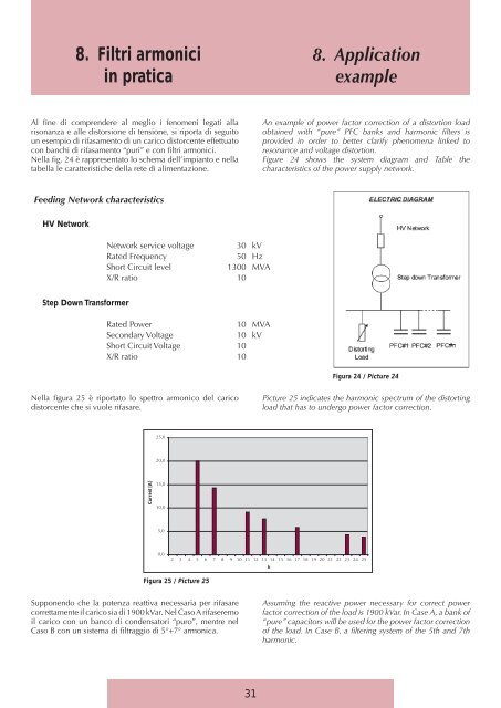
Nella figura 25 è riport<strong>at</strong>o lo spettro armonico del carico<br />
distorcente che si vuole rifasare.<br />
Picture 25 indic<strong>at</strong>es the harmonic spectrum of the distorting<br />
load th<strong>at</strong> has to undergo power factor correction.<br />
25,0<br />
20,0<br />
Current [A]<br />
15,0<br />
10,0<br />
5,0<br />
0,0<br />
2 3 4 5 6 7 8 9 10 11 12 13 14 15 16 17 18 19 20 21 22 23 24 25<br />
h<br />
Figura 25 / Picture 25<br />
Supponendo che la potenza re<strong>at</strong>tiva necessaria per rifasare<br />
correttamente il carico sia di 1900 kVar. Nel Caso A rifaseremo<br />
il carico con un banco di <strong>condens<strong>at</strong>ori</strong> “puro”, mentre nel<br />
Caso B con un sistema di filtraggio di 5°+7° armonica.<br />
Assuming the reactive power necessary for correct power<br />
factor correction of the load is 1900 kVar. In Case A, a bank of<br />
“pure” <strong>capacitors</strong> will be used for the power factor correction<br />
of the load. In Case B, a filtering system of the 5th and 7th<br />
harmonic.<br />
31