MASTER FLUX AUTOMATIC AS 3000 - CreativDental
MASTER FLUX AUTOMATIC AS 3000 - CreativDental
MASTER FLUX AUTOMATIC AS 3000 - CreativDental

You also want an ePaper? Increase the reach of your titles
YUMPU automatically turns print PDFs into web optimized ePapers that Google loves.
d e n t a l a n d m e d i c a l e q u i p m e n t<br />
Istruzioni per l’uso<br />
Instructions for use<br />
Mode d’emploi<br />
Bedienungsanleitung<br />
Istrucciones para el uso<br />
<strong>M<strong>AS</strong>TER</strong> <strong>FLUX</strong><br />
<strong>AUTOMATIC</strong> <strong>AS</strong> <strong>3000</strong><br />
Art. 1500/<strong>AS</strong><br />
Art. 1501/<strong>AS</strong>
TECNO-GAZ, La ringrazia di aver acquistato un prodotto della sua gamma e la invita alla<br />
lettura, in ogni parte del presente Manuale Istruzione.<br />
All’interno troverà tutte le istruzioni necessarie per un corretto utilizzo del prodotto.Si<br />
prega di seguire attentamente le avvertenze contenute, di conservarlo inalterato,<br />
facilmente reperibile ed accessibile all’operatore.<br />
Il contenuto del presente Manuale può essere modificato, senza preavviso ne ulteriori<br />
obblighi, al fine di includere variazioni e miglioramenti.<br />
È vietata la riproduzione o la traduzione di qualsiasi parte del presente manuale senza il<br />
consenso scritto di TECNO-GAZ.<br />
La informiamo che la ns. Ditta rimane a Sua completa disposizione per fornire notizie e<br />
delucidazioni in merito a tutto quanto concerne l’utilizzo del prodotto.<br />
Grazie e buon lavoro<br />
TECNO-GAZ S.p.A.<br />
TECNO-GAZ wishes to thank you for your purchasing one of its range of products and<br />
you are invited to read this booklet thoroughly.<br />
This booklet contains all of the information necessary to use the product correctly.<br />
Please adhere closely to the notices contained within and conserve the booklet, without<br />
making changes, in a place where it is easy to find and is accessible to the operator.<br />
The contents of this manual can be changed, without warning or additional obligations, so<br />
that the manufacturer can include variations and improvements.<br />
It is prohibited to copy or translate any of this booklet without the written permission of<br />
TECNO-GAZ.<br />
Our Company remains at your complete disposal to provide any kind of information you<br />
may need for operating the appliance.<br />
Again thank you and good work.<br />
TECNO-GAZ S.p.A.<br />
1 DMFF001 - Rev. 6
INDICE - INDEX<br />
ITALIANO 7 - 37<br />
ENGLISH 38 - 68<br />
2 DMFF001 - Rev. 6
PAR. 1<br />
DICHIARAZIONE DI CONFORMITÀ<br />
CONFORMITY STATEMENT<br />
La sottoscritta – The company:<br />
TECNO-GAZ S.p.A. - Strada Cavalli n.4 - 43038 Sala Baganza - Parma - Italia.<br />
Dichiara sotto la propria responsabilità, che il Dispositivo Medico per analgesia sedativa:<br />
Declares under its own responsibility that the Medical Device for sedative analgesia:<br />
VERSIONI<br />
VERSIONS<br />
<strong>M<strong>AS</strong>TER</strong> <strong>FLUX</strong> <strong>AUTOMATIC</strong> <strong>AS</strong> <strong>3000</strong>:<br />
Art. 1500-<strong>AS</strong> (Dispositivo a mobile - Cabinet device)<br />
Art. 1501-<strong>AS</strong> (Dispositivo a parete per impianti centralizzati - Wall-type device<br />
for centralized systems)<br />
TARGHETTA<br />
PLATE<br />
costruito da TECNO-GAZ S.p.A., è conforme alle disposizioni legislative che traspongono la Direttiva Dispositivi<br />
Medici 93/42/CEE del 14 Giugno 1993, applicata in Italia dal Decreto Legislativo N.46 del 24 Febbraio 1997.<br />
Manufactured by TECNO-GAZ S.p.A. complies with Medical Equipment Directive 93/42/EEC of 14 June 1993,<br />
which corresponds to the Italian Decreto Legislativo N.46 of 24 February 1997.<br />
Durata :<br />
Period:<br />
Descrizione:<br />
Description:<br />
Classe:<br />
Class:<br />
Classificazione in riferimento all’articolo 9,12 e allegato IX della Direttiva 93/42/CEE<br />
Classification referred to the article 9,12 and annex IX of the Directive 93/42/EEC<br />
Temporanea (art.1, comma 1.1, allegato IX)<br />
Temporary (art.1, § 1.1, annex IX)<br />
Dispositivo Medico non invasivo (art.1, comma 1.2, allegato IX)<br />
Non-invasive Medical Device (art.1, § 1.2, annex IX)<br />
Dispositivo Medico attivo (art.1, comma 1.4, allegato IX)<br />
Active Medical Device (art.1, § 1.4, annex IX)<br />
Classe IIA (Par.3 “CL<strong>AS</strong>SIFICAZIONE” Regola 2-11, allegato IX)<br />
Class IIA (Par.3 “CL<strong>AS</strong>SIFICATION” Rule 2-11, annex IX)<br />
Nome - Name: Paolo BERTOZZI<br />
Posizione - Position: Presidente – Chairman<br />
0051<br />
3 DMFF001 - Rev. 6
PAR. 2<br />
MARCATURA CE & RINTRACCIABILITÀ<br />
CE MARKING AND IDENTIFICATION<br />
Il Dispositivo Medico <strong>M<strong>AS</strong>TER</strong> <strong>FLUX</strong> è progettato e costruito, secondo quanto previsto dalla direttiva<br />
93/42/CEE.<br />
La conformità è documentata dalla targhetta con marchio CE (qui di seguito raffigurata) e dalla<br />
dichiarazione di conformità che accompagna il presente libretto.<br />
The Medical Device <strong>M<strong>AS</strong>TER</strong> <strong>FLUX</strong> is projected and manufactured according to what requested by the<br />
Directive 93/42/EEC.<br />
The full compliance is evidenced by both the CE mark plate (see picture enclosed) and the declaration of<br />
conformity accompanying this booklet.<br />
Targhetta di marcatura CE scatola flussometrica <strong>M<strong>AS</strong>TER</strong> <strong>FLUX</strong><br />
<strong>M<strong>AS</strong>TER</strong> <strong>FLUX</strong>’s flow-meter box CE marking label<br />
Nome del fabbricante<br />
Name of the manufacturer<br />
Articolo del prodotto finito<br />
Article of final product<br />
Numero di Matricola<br />
Serial number<br />
Leggere il Manuale<br />
Read user’s Manual<br />
Lotto di produzione<br />
Production lot<br />
Peso<br />
Weight<br />
Marcatura in riferimento alla<br />
Direttiva 93/42/CEE + Numero<br />
dell’Organismo notificato<br />
Marking with reference to the<br />
Directive 93/42/EEC + Number<br />
of notified Body<br />
Articolo di vendita<br />
Sold item<br />
Etichetta di rintracciabilità scatola flussometrica <strong>M<strong>AS</strong>TER</strong> <strong>FLUX</strong><br />
<strong>M<strong>AS</strong>TER</strong> <strong>FLUX</strong>’s flow-meter box identification label<br />
Lotto di produzione<br />
Production lot<br />
Numero di Matricola<br />
Serial number<br />
Codice rintracciabilità<br />
Etichetta<br />
Identification label code<br />
L’etichetta Rintracciabilità degli accessori del <strong>M<strong>AS</strong>TER</strong> <strong>FLUX</strong> è analoga a quella del dispositivo.<br />
<strong>M<strong>AS</strong>TER</strong> <strong>FLUX</strong>’s equipment identification label is similar to this one<br />
La targhetta è posta sul lato sinistro della scatola flussometrica vista frontalmente.<br />
La rintracciabilità del Dispositivo Medico <strong>M<strong>AS</strong>TER</strong> <strong>FLUX</strong> è data dal numero di matricola della scatola<br />
flussometrica in adempimento all’istruzione interna AQ-I-005.<br />
The identification label is located on the left side of the flow-meter box.<br />
You identify the <strong>M<strong>AS</strong>TER</strong> <strong>FLUX</strong> Medical Device by the flow-meter box’s serial number according to the our<br />
internal instructions AQ-I-005.<br />
4 DMFF001 - Rev. 6
PAR. 3<br />
<strong>AS</strong>SISTENZA TECNICA<br />
TECHNICAL <strong>AS</strong>SISTANCE<br />
TUTTI GLI INTERVENTI DI <strong>AS</strong>SISTENZA TECNICA E RIPARAZIONE SONO ESEGUITI DIRETTAMENTE<br />
DALLA DITTA TECNO-GAZ NEL PROPRIO LABORATORIO PROVE E RIPARAZIONI.<br />
ALL TECHNICAL <strong>AS</strong>SISTANCE AND REPAIRS ARE TO BE CARRIED OUT DIRECTLY BY THE COMPANY<br />
TECNO-GAZ IN ITS OWN TEST AND REPAIR LABORATORY.<br />
Str. Cavalli n°4 – Sala Baganza–Parma – ITALIA.<br />
Tel. +39 0521 833926 - Fax +39 0521 833391<br />
e-mail : info@tecnogaz.com<br />
http://www.tecnogaz.com<br />
5 DMFF001 - Rev. 6
PAR. 4<br />
GARANZIA<br />
Il prodotto è coperto da garanzia, per un periodo di dodici mesi ad esclusione delle membrane in<br />
movimento, per le quali la garanzia è di sei mesi.<br />
Detta garanzia ha inizio dalla data di consegna del prodotto al cliente, comprovata dalla restituzione del<br />
tagliando di garanzia debitamente compilato, timbrato e firmato dal rivenditore.<br />
In caso di contestazione, è ritenuta valida la data indicata sulla bolla di vendita.<br />
La riparazione o la sostituzione in garanzia di un particolare, è effettuata ad insindacabile giudizio della casa<br />
e non comprende, la trasferta del personale e le spese d’imballaggio e trasporto.<br />
Sono escluse dalla garanzia guasti o danni derivati da una cattiva manutenzione, negligenza, imperizia o<br />
altre cause non imputabili al costruttore.<br />
I componenti soggetti a normale usura e gli accessori non sono compresi nella garanzia.<br />
Non è riconosciuto il diritto alla sostituzione del prodotto completo.<br />
La garanzia non comporta alcun risarcimento danni diretti o indiretti di qualsiasi natura verso persone o<br />
cose, dovuti all’eventuale inefficienza del prodotto.<br />
La garanzia decade automaticamente qualora il prodotto sia manomesso, riparato o modificato<br />
dall'acquirente o da terzi non autorizzati.<br />
Per gli interventi, l'acquirente deve rivolgersi unicamente al rivenditore oppure ai centri d’assistenza indicati<br />
dal costruttore.<br />
I componenti sostituiti in garanzia devono essere restituiti alla TECNO-GAZ in porto franco.<br />
La mancata restituzione, comporta l'addebito del costo del particolare al richiedente.<br />
WARRANTY<br />
This equipment is covered by warranty for twelve months, with the exception of moving membranes, which<br />
are covered by warranty for six months.<br />
This warranty starts on date of delivery of the equipment to the customer, as proved by the warranty<br />
coupon which has to be returned duly filled, stamped and signed by the seller.<br />
In case of controversy, the date shown on the sales note will be applied.<br />
Warranty repair or replacement of a part is at the manufacturer's unquestionable discretion and does not<br />
include personnel's transfer and package and transport freight.<br />
Breakdowns resulting from poor maintenance, negligence, unskilful use or other causes not depending on<br />
the manufacturer will be excluded from warranty.<br />
Wear parts and fittings are excluded from warranty.<br />
The manufacturer does not acknowledge the right of replacement of the complete equipment.<br />
This warranty does not imply any compensation for direct or indirect damages of any kind to people or<br />
property due to equipment inefficiency.<br />
This warranty will automatically void if the equipment is tampered with, repaired or altered by the buyer or<br />
any unauthorised third party.<br />
When servicing is required, the buyer shall only apply to the seller or services indicated by the<br />
manufacturer.<br />
Components replaced under warranty shall be returned to TECNO-GAZ free of carriage.<br />
If components are not returned, their cost will be charged to the applicant.<br />
6 DMFF001 - Rev. 6
INDICE<br />
PAR.<br />
PAG.<br />
1 Dichiarazione di Conformità CE ................................................................................................. 3<br />
2 Marcatura CE.............................................................................................................................. 4<br />
3 Assistenza................................................................................................................................... 5<br />
4 Garanzia...................................................................................................................................... 6<br />
5 Avvertenze e nozioni utili ......................................................................................................8 - 9<br />
6 Caratteristiche tecniche ....................................................................................................10 - 11<br />
7 Imballo, trasporto e stoccaggio ............................................................................................... 12<br />
8 Accessori in dotazione ............................................................................................................. 13<br />
9 Impiego..................................................................................................................................... 14<br />
9.1 Concetti basilari della Sedazione....................................................................................................................... 14<br />
10 Figure .........................................................................................................................15 - 17 - 18<br />
11 Installazione & Collegamenti.................................................................................................... 19<br />
11.1 Installazione Master Flux a mobile, cod.1500/<strong>AS</strong>............................................................... 19 - 20 - 21 – 22 - 23<br />
11.2 Installazione Master Flux a parete,cod.1501/<strong>AS</strong> ............................................................................... 24 - 25 - 26<br />
11.3 Collegamento tubo spiralato............................................................................................................................ 26<br />
11.4 Collegamento pallone in gomma..................................................................................................................... 26<br />
11.5 Collegamento maschere (cod. 1524/S & 1525/S)........................................................................................... 27<br />
11.6 Collegamento tubo erogazione ....................................................................................................................... 27<br />
11.7 Evacuazione gas esalati............................................................................................................................ 28 - 29<br />
Scarico tramite aspiratore chirurgico dei gas direttamente dalla maschera................................................... 28<br />
Scarico dei gas all’esterno tramite il mobile .................................................................................................... 28<br />
Scarico in esterno dei gas direttamente dalla mascherina.............................................................................. 29<br />
11.8 Regolazione valvola di scarico.......................................................................................................................... 29<br />
12 Istruzione per l’uso ................................................................................................................... 30<br />
12.1 Inizi terapia ....................................................................................................................................................... 30<br />
12.2 Specifiche di terapia per bambini .................................................................................................................... 30<br />
12.3 Specifiche di terapia per adulti ........................................................................................................................ 30<br />
12.4 Fine terapia....................................................................................................................................................... 31<br />
12.5 Situazioni che si possono verificare durante il funzionamento ....................................................................... 33<br />
12.6 Stabilità durante l’uso...................................................................................................................................... 33<br />
12.7 Rianimazione con il Master Flux utilizzando il KIT Art.1504/A......................................................................... 34<br />
13 Manutenzione ....................................................................................................................35 - 36<br />
14 Conclusioni............................................................................................................................... 37<br />
7 DMFF001 - Rev. 6
PAR. 5<br />
AVVERTENZE & NOZIONI UTILI<br />
(le posizioni e i codici sotto riportate sono da verificare con le figure del Par.10)<br />
1. A FINE TERAPIA SOMMINISTRARE SEMPRE OSSIGENO PURO PER DUE MINUTI<br />
2. Il paziente deve sempre mantenere la mascherina sul naso indipendentemente dalla durata<br />
dell’intervento.<br />
3. Il paziente va trattato in ambiente tranquillo privo di rumori con meno persone possibile attorno.<br />
4. Bisogna indurre il paziente all’uso della mascherina con pazienza, facendogli capire che la cosa è a<br />
suo vantaggio.<br />
5. Durante l’intervento è indispensabile essere sempre presenti e tenere sotto controllo il pallone in<br />
gomma Pos. A (Cod.CM84001) e gli indicatori di portata Pos. B e Pos. C (Cod.CM87047,<br />
CM87048).Vedi Fig. 1<br />
6. Durante la sedazione è indispensabile essere sempre presenti<br />
e mantenere sotto controllo i flussi dei gas di ossigeno e<br />
protossido verificando i valori riportati dalle colonnine, nonché<br />
il volume dei gas somministrati, mediante la sacca di controllo.<br />
FIG.1<br />
7. Il paziente deve essere sdraiato il più possibile sulla poltrona<br />
(compatibilmente con l’intervento che dovrà essere eseguito),<br />
con le gambe e le braccia distese (non accavallate).<br />
8. Per trasmettere maggiore sicurezza al paziente che si sta<br />
trattando, è consigliabile tranquillizzarlo verbalmente,<br />
appoggiandogli una mano sulla spalla. Si unirà così l’azione<br />
farmacologica a quella psicologica.<br />
9. Durante l’intervento è buona norma chiedere al paziente come<br />
si sente, rivolgendogli domande del tipo: “TI SENTI BENE”, “SEI RIL<strong>AS</strong>SATO”, “POSSO<br />
PROCEDERE”. In base alle risposte, si valuterà lo stato di sedazione e si potrà decidere se<br />
mantenere o variare (aumentando o diminuendo) la percentuale di somministrazione.<br />
10. Al paziente molto piccolo (3/7 anni) risulta sovente difficile l’applicazione della mascherina in quanto<br />
anche questa genera ansia. Solitamente il bambino è persuaso dopo che il medico o un familiare<br />
hanno provato la mascherina. Si possono usare frasi fantasiose del tipo “ E’ LA M<strong>AS</strong>CHERINA DEGLI<br />
<strong>AS</strong>TRONAUTI” etc.<br />
C<br />
B<br />
A<br />
11. Precisiamo che i valori di somministrazione flussi che<br />
riporteremo in seguito sono medi ma comunque molto<br />
attendibili, quindi consigliamo di seguirli il più possibile.<br />
FIG.2<br />
12. Se il paziente accusa sintomi di malessere (nausea, vertigine,<br />
mal di testa) sulla scatola flussometrica è previsto un pulsante<br />
“FLUSH” Pos. D (Cod.SMFA032).Vedi Fig. 2<br />
Premendo il pulsante “FLUSH” il pallone<br />
(Cod. CM84001) si riempirà di ossigeno che<br />
andremo a somministrare manualmente al paziente;<br />
nel caso interrompere la terapia. Vedi Fig. 2<br />
D<br />
8 DMFF001 - Rev. 6
13. Non lubrificare mai nessun organo del dispositivo medico.<br />
14. Le bombole destinate ad alimentare un impianto centralizzato devono essere ubicate in un ambiente<br />
facilmente accessibile, asciutto, pavimento antistatico, con bocche di areazione in diretta<br />
comunicazione con l’esterno.<br />
15. Le bombole devono essere fissate alla parete tramite un sistema antiribaltamento (catena, ecc…) e<br />
protette da una barriera (griglia, ce…) che le tuteli contro urti e manomissioni.<br />
16. Non alloggiare le bombole vicino a fonti di calore (es. radiatori, centrali termiche, canne fumarie,<br />
ecc…).<br />
17. Non installare le bombole in ambienti a rischio come depositi di sostanze infiammabili, composti<br />
chimici o a contatto con componenti elettrici.<br />
18. Collegare a terra i tubi dell’impianto centralizzato.<br />
19. Non oliare o ingrassare nessun componente dell’impianto.<br />
20. Quanto indicato qui sopra sono solo alcune osservazioni da seguire durante lo sviluppo dell’impianto<br />
centralizzato.<br />
21. FARE ESEGUIRE L’IMPIANTO CENTRALIZZATO AD UNA DITTA SPECIALIZZATA CHE RIL<strong>AS</strong>CI<br />
DICHIARAZIONE D’IMPIANTO A REGOLA D’ARTE (In riferimento alle norme vigenti nei paesi di<br />
utilizzo).<br />
22. Non appoggiare alcun oggetto sulla scatola flussometrica e sul mobile.<br />
23. PRIMA DI CARICARE LE BOMBOLE INDICARE, SUI RISPETTIVI COLLARI, LA PARTITA IVA DEL<br />
PROPRIETARIO (SOLO PER IL MERCATO ITALIANO).<br />
9 DMFF001 - Rev. 6
PAR. 6<br />
CARATTERISTICHE TECNICHE<br />
Pressione massima d’alimentazione: 3.5 Bar ≅ 50 PSI<br />
Portata massima erogabile: 10 l/min. (litri al minuto)<br />
INGOMBRI <strong>M<strong>AS</strong>TER</strong> <strong>FLUX</strong> A MOBILE:<br />
FIG.3<br />
Le misure riportate<br />
nelle figure sono<br />
espresse in millimetri<br />
(mm)<br />
Peso senza bombole: 42 Kg<br />
Peso con bombole capacità 5 Lt: 63 Kg<br />
Peso con bombole capacità 10 Lt: 81 Kg<br />
Altezza max (comprensivo di valvola): 950 mm<br />
Diametro max: 140 mm<br />
Colore: Bianco RAL 9002<br />
Il mobile può contenere 2 bombole da 5 litri o due bombole da 10 litri, ma possono essere montate<br />
bombole diverse.<br />
10 DMFF001 - Rev. 6
INGOMBRI <strong>M<strong>AS</strong>TER</strong> <strong>FLUX</strong> A PARETE:<br />
Le misure riportate<br />
nelle figure sono<br />
espresse in<br />
millimetri (mm)<br />
FIG.4<br />
Massa complessiva della scatola flussometrica (comprensiva di pallone e tubo spiralato): 6.27Kg.<br />
CONSUMI:<br />
A seguire è indicato un esempio di consumo da prendere come riferimento teorico<br />
BOMBOLA OSSIGENO CON CAPACITA’ 10Lt. CARICATA ALLA PRESSIONE DI 200 Bar<br />
VOLUME D’OSSIGENO DISPONIBILE Litri Gassosi 2000.<br />
BOMBOLA PROTOSSIDO CON CAPACITA’ 10Lt. CARICATA CON 7 Kg. DI G<strong>AS</strong> LIQUIDO<br />
VOLUME DI PROTOSSIDO (G<strong>AS</strong>) DISPONIBILE Litri Gassosi 4600<br />
IMPOSTANDO:<br />
EROGAZIONE 10 NLt./min.<br />
MISCELAZIONE 50%<br />
AUTONOMIA:<br />
OSSIGENO:<br />
PROTOSSIDO:<br />
400 min.<br />
920 min.<br />
11 DMFF001 - Rev. 6
PAR. 7<br />
IMBALLO, TR<strong>AS</strong>PORTO E STOCCAGGIO<br />
IMBALLO <strong>M<strong>AS</strong>TER</strong> <strong>FLUX</strong> A MOBILE, ART.1500/<strong>AS</strong>:<br />
Il <strong>M<strong>AS</strong>TER</strong> <strong>FLUX</strong> a mobile, è spedito in 3 imballi separati:<br />
- SCATOLA FLUSSOMETRICA<br />
- KIT <strong>M<strong>AS</strong>TER</strong> <strong>FLUX</strong> A MOBILE<br />
- MOBILE COMPLETO PER <strong>M<strong>AS</strong>TER</strong> <strong>FLUX</strong><br />
La scatola flussometrica, chiusa in un sacchetto di cellophane è inserita in due sagome di polistirolo<br />
espanso a loro volta richiuse in una scatola di cartone ondulato.<br />
Il Kit <strong>M<strong>AS</strong>TER</strong> <strong>FLUX</strong> a mobile è composto dagli accessori da usare, chiusi in una scatola di cartone<br />
ondulato.<br />
Il mobile completo per <strong>M<strong>AS</strong>TER</strong> <strong>FLUX</strong> è coperto da un sacchetto di cellophane chiuso in un cartone<br />
ondulato, il tutto fissato ad un piedistallo in legno (pallet).<br />
IMBALLO <strong>M<strong>AS</strong>TER</strong> <strong>FLUX</strong> A PARETE, ART.1501/<strong>AS</strong>:<br />
Il <strong>M<strong>AS</strong>TER</strong> <strong>FLUX</strong> a mobile, è spedito in 3 imballi separati:<br />
- SCATOLA FLUSSOMETRICA<br />
- KIT <strong>M<strong>AS</strong>TER</strong> <strong>FLUX</strong> A PARETE<br />
- KIT SUPPORTO A PARETE <strong>M<strong>AS</strong>TER</strong> <strong>FLUX</strong><br />
La scatola flussometrica, chiusa in un sacchetto di cellophane è inserita in due sagome di polistirolo<br />
espanso a loro volta richiuse in una scatola di cartone ondulato.<br />
Il Kit <strong>M<strong>AS</strong>TER</strong> <strong>FLUX</strong> a parete è composto dagli accessori da usare, chiusi in una scatola di cartone<br />
ondulato.<br />
Il KIT SUPPORTO A PARETE <strong>M<strong>AS</strong>TER</strong> <strong>FLUX</strong> è composto dagli accessori da usare per fissare al muro la<br />
scatola flussometrica, chiusi in una scatola di cartone ondulato.<br />
Non disperdere il materiale dell’imballo nell’ambiente.<br />
I dispositivi imballati devono essere custoditi in luoghi asciutti e a temperatura compresa tra (+5/+40)°C.<br />
Non è consentita la sovrapposizione di due o più imballi mobile Master Flux.<br />
12 DMFF001 - Rev. 6
PAR. 8<br />
ACCESSORI IN DOTAZIONE<br />
ACCESSORI IN DOTAZIONE NEL <strong>M<strong>AS</strong>TER</strong> <strong>FLUX</strong> A MOBILE art. 1500/<strong>AS</strong>:<br />
- N.1 Scatola flussometrica (COD. SMFA500) che comprende:<br />
- N.1 Manuale Istruzioni (COD.DMFF001)<br />
N.1 Pallone 2.7 litri (COD. CM84001)<br />
N.1 Tubo spiralato trasparente (COD. CM88051)<br />
- N.1 Mobile Master Flux (COD. SMFA186) che comprende:<br />
- N.1 Filtro evacuazione gas esalati completo (COD. SMFA260)<br />
- N.1 Tubo per l’evacuazione gas (COD.SMFA197)<br />
- N.3 distanziatori per scatola flussometrica (COD. SMFA223)<br />
- N.3 Dadi autobloccanti (COD. CM10004)<br />
- N.3 Rosette (COD. CM20004)<br />
- N.1 Chiave Ø10 (COD.CM45004)<br />
- N°3 Distanziatori (COD. SMFA178)<br />
N°1 Kit Master Flux a mobile (Cod. SMFA496) che comprende:<br />
- N.1 Riduttore N 2 O MATER <strong>FLUX</strong> a mobile (COD.1515/A3)<br />
- N.1 Riduttore O 2 <strong>M<strong>AS</strong>TER</strong> <strong>FLUX</strong> a mobile (COD. 1513/A3)<br />
- N.1 Chiave Ø 22 (COD.CM45006)<br />
- N.1 Maschera piccola (COD.1525/A) - KIT<br />
- N.1 Maschera grande (COD.1524/A) - KIT<br />
ACCESSORI IN DOTAZIONE NEL <strong>M<strong>AS</strong>TER</strong> <strong>FLUX</strong> A PARETE art. 1501/<strong>AS</strong>:<br />
- N.1 Scatola flussometrica (COD. SMFA500) che comprende:<br />
- N.1 Manuale Istruzioni (COD.DMFF001)<br />
- N.1 Pallone 2.7 litri (COD. CM84001)<br />
- N.1 Tubo spiralato trasparente (COD. CM88051)<br />
- Kit <strong>M<strong>AS</strong>TER</strong> <strong>FLUX</strong> a parete (COD. SMFA497) che comprende:<br />
N.1 Riduttore N 2 O MATER <strong>FLUX</strong> a parete (COD. SMFA360)<br />
- N.1 Riduttore O 2 <strong>M<strong>AS</strong>TER</strong> <strong>FLUX</strong> a parete (COD.SMFA359)<br />
- N.1 Chiave Ø 22 (COD.CM45005)<br />
- N.1 Maschera piccola (COD.1525/A) - KIT<br />
- N.1 Maschera grande (COD.1524/A) - KIT<br />
- N.1 Filtro evacuazione gas esalati completo (COD. SMFA260)<br />
- N.1 Tubo per l’evacuazione gas (COD.SMFA197)<br />
N.1 tubo O2 per scatola fluss.(Cod.SMFA364)<br />
N.1 Tubo N2 O per scatola fluss. (Cod. SMFA365)<br />
N.1 Piastra con innesti rapidi (Cod. SMFA501)<br />
Kit supporto a muro Master Flux (Cod. SMFA301) che comprende:<br />
N.1 Impugnatura (Cod. SMFA313)<br />
N.1 braccetto completo<br />
N.1 cerniera completa<br />
13 DMFF001 - Rev. 6
PAR. 9<br />
IMPIEGO<br />
IL <strong>M<strong>AS</strong>TER</strong> <strong>FLUX</strong> DEVE ESSERE UTILIZZATO SOLO DA PERSONALE (ODONTOIATRI E<br />
PERSONALE INFERMIERISTICO) CHE ABBIA RICEVUTO UNA SPECIFICA<br />
PREPARAZIONE.<br />
9.1 CONCETTI B<strong>AS</strong>ILARI DELLA SEDAZIONE:<br />
È bene precisare che la sedazione, è quella particolare tecnica studiata e messa a punto dal Dr. LANGA, il<br />
quale ha scoperto che somministrando una miscela d’ossigeno e protossido d’azoto si annullano<br />
completamente gli stati di ANSIA e PAURA che accusano diversi pazienti prima di affrontare le cure<br />
odontoiatriche.<br />
Importanza fondamentale è che il protossido d’azoto non deve mai superare il 70% della miscela.<br />
Sebbene i gas usati in sedazione siano gli stessi utilizzati in anestesia, è fondamentale non confondere le<br />
due pratiche, in quanto le “SEDATION MACHINES” non permettono meccanicamente di mandare il<br />
paziente in anestesia totale.<br />
Effetti importanti derivanti dalla sedazione riguardanti l'apparato orale sono:<br />
1) Un discreto innalzamento della soglia del dolore.<br />
2) Deglutizione meno frequente.<br />
3) Senso di nausea ridotto notevolmente.<br />
Somministrare anestesia ove necessario, anche in presenza di Analgesiterapia, in quanto<br />
quest’ultima ha solo effetto sedativo (toglie l'ANSIA e la PAURA al paziente).<br />
La sedazione è un trattamento che il medico esegue sul paziente, facendolo sentire disteso e rilassato.<br />
È utile anche al medico, in quanto potrà lavorare con minori perdite di tempo e maggiore tranquillità.<br />
Il <strong>M<strong>AS</strong>TER</strong> <strong>FLUX</strong> <strong>AUTOMATIC</strong> <strong>AS</strong> <strong>3000</strong> permette di somministrare PROTOSSIDO D’AZOTO (N 2 O) come<br />
sedativo, miscelato a OSSIGENO (O 2 ) in percentuale dallo 0 a circa il 70%, graduabile a seconda<br />
dell'ansia e della paura del paziente.<br />
Per ottenere una corretta sedazione, l'odontoiatra dovrà porre attenzione a soddisfare le seguenti<br />
condizioni:<br />
- DEVE ESSERE SOMMINISTRATO UN VOLUME DI G<strong>AS</strong> SUFFICIENTE (alla capacità polmonare del<br />
paziente).<br />
A tale scopo il pallone di controllo deve presentarsi pieno a metà (mezzo pieno e mezzo vuoto).<br />
- DEVE ESSERE SOMMINISTRATA UNA PERCENTUALE DI PROTOSSIDO D’AZOTO PIU’ B<strong>AS</strong>SA<br />
POSSIBILE, CHE SIA PERO’ SUFFICIENTE PER OTTENERE UNA BUONA SEDAZIONE (= B<strong>AS</strong>E LINE).<br />
Quando il paziente avverte formicolio diffuso, caldo agli arti o sensazione di leggerezza, è in pratica sedato,<br />
quindi è raggiunto il B<strong>AS</strong>E LINE. Questo B<strong>AS</strong>E LINE di solito non varia nello stesso paziente. Basta<br />
segnarlo sulla sua cartella clinica e nelle sedute successive s’inizierà direttamente la somministrazione del<br />
gas con questi flussi.<br />
14 DMFF001 - Rev. 6
PAR. 10<br />
FIGURE<br />
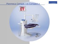
<strong>M<strong>AS</strong>TER</strong> <strong>FLUX</strong> A MOBILE, COD. 1500/<strong>AS</strong>:<br />
FIG.5<br />
MOBILE<br />
<strong>M<strong>AS</strong>TER</strong> <strong>FLUX</strong><br />
Cod.SMFA186<br />
SCATOLA<br />
FLUSSOMETRICA<br />
<strong>M<strong>AS</strong>TER</strong> <strong>FLUX</strong><br />
Cod.SMFA500<br />
TUBO<br />
SPIRALATO<br />
Cod.CM88051<br />
M<strong>AS</strong>CHERA<br />
<strong>M<strong>AS</strong>TER</strong> <strong>FLUX</strong><br />
Cod.1524-A (Grande)<br />
Cod. 1525-A (Piccola)<br />
PALLONE IN<br />
GOMMA<br />
Cod.CM84001<br />
PORTAGOMMA<br />
Cod.SMFA237<br />
PORTAGOMMA<br />
Cod.SMFA237<br />
15 DMFF001 - Rev. 6
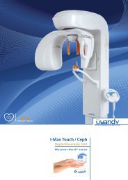
<strong>M<strong>AS</strong>TER</strong> <strong>FLUX</strong> A PARETE, COD. 1501/<strong>AS</strong>:<br />
FIG.6<br />
Tubo N 2 O<br />
SMFA365<br />
Piastra<br />
fissaggio a<br />
muro<br />
SMFA501<br />
Scatola<br />
flussometrica<br />
SMFA500<br />
Tubo O 2<br />
SMFA364<br />
Impugnatura-<br />
Perno a muro<br />
SMFA313<br />
Supporto<br />
<strong>M<strong>AS</strong>TER</strong> <strong>FLUX</strong><br />
A MURO<br />
SMFA301<br />
Maschera<br />
<strong>M<strong>AS</strong>TER</strong> <strong>FLUX</strong><br />
1524-A (grande)<br />
1525-A (piccola)<br />
PALLONE IN<br />
GOMMA<br />
CM84001<br />
16 DMFF001 - Rev. 6
M<strong>AS</strong>CHERE <strong>M<strong>AS</strong>TER</strong> <strong>FLUX</strong> , COD. 1524/A, 1525/A<br />
FIG.7<br />
Innesto per aspirazione chirurgica<br />
SMFA229<br />
Raccordo portagomma (in dotazione al mobile SMFA186)<br />
SMFA237<br />
Tubo spiralato<br />
per maschera<br />
SMFA240<br />
L=130cm<br />
Valvola<br />
eliminazione gas<br />
SMFA236<br />
Raccordo per<br />
evacuazione parete<br />
SMFA257<br />
Innesto tubo<br />
maschera<br />
SMFA229<br />
SMFA225 (Maschera grande)<br />
SMFA226 (Maschera piccola)<br />
Tubo spiralato<br />
per maschera<br />
SMFA240<br />
L=130 cm INNESTO<br />
MONOTUBO<br />
SMFA228<br />
17 DMFF001 - Rev. 6
SCATOLA FLUSSOMETRICA, COD.SMFA500:<br />
FIG.8<br />
MANOPOLA<br />
”FLOW”<br />
Cod. SMFA001<br />
PORTAGOMMA<br />
TUBO SPIRALATO<br />
Cod. SMFA088<br />
PULSANTE<br />
“FLUSH”<br />
Cod. SMFA032<br />
PORTAGOMMA<br />
PALLONE<br />
Cod.SMFA088<br />
MANOPOLA<br />
“N 2 O%”<br />
Cod. SMFA040<br />
INDICATORI DI<br />
PORTATA<br />
Cod. CM87047 (N 2 O)<br />
Cod. CM87048 (O 2 )<br />
18 DMFF001 - Rev. 6
PAR. 11<br />
INSTALLAZIONE E COLLEGAMENTI<br />
11.1 INSTALLAZIONE <strong>M<strong>AS</strong>TER</strong> <strong>FLUX</strong> A MOBILE, COD. 1500/<strong>AS</strong>:<br />
1) - MONTAGGIO ROTELLE (Vedi Fig.9)<br />
A - Togliere dall’imballo il mobile.<br />
B - Posizionare il mobile ‘C’ orizzontalmente su un piano morbido (tappeto, ecc.) per il montaggio delle<br />
rotelle.<br />
C - Imboccare manualmente le rotelle ‘A’ nelle apposite sedi.<br />
D - Completare l’avvitamento delle rotelle con chiave fissa da 13 mm ‘F’ (Fig.9)<br />
2) - MONTAGGIO MANIGLIA E SUPPORTO LATERALE (Vedi Fig. 10 e 11)<br />
A - Smontare il pannello ‘B’ dal mobile ‘C’.<br />
B - Montare la maniglia laterale ‘E’ al mobile con le apposite viti e spessori (avvitando le viti dall’interno del<br />
mobile con cacciavite a croce).<br />
C - Analogamente montare il supporto maschera laterale ‘D’.<br />
D - Mettere il mobile in posizione verticale sulle ruote.<br />
E - Controllare la stabilità del mobile trascinandolo per la stanza.<br />
F - Controllare il montaggio.<br />
3) - MONTAGGIO SCATOLA FLUOSSOMETRICA<br />
A - Togliere dall’imballo la scatola flussometrica.<br />
B - Avvitare i 3 distanziatori (cod. SMFA223) sulla scatola flussometrica (cod. SMFA500) (Vedi Fig. 12).<br />
Togliere le protezioni in silicone dai nipples di alimentazione e di mandata. Montare la scatola flussometrica<br />
sul mobile inserendo i supporti A,B,C, rispettivamente nei fori 1,2,3. (Vedi Fig. 13).<br />
C - Fissare i supporti al mobile utilizzando i tre distanziatori Cod. SMFA178 , le 3 rosette (cod. CM20004) e i<br />
3 dadi (cod. CM10004), per serrare i dadi utilizzare la chiave 10 mm (cod. CM45004). (Vedi Fig.14).<br />
4) - MONTAGGIO BOMBOLE<br />
A - Togliere le bombole dal proprio imballo. Scrivere sul collare della bombola OX la partita iva. Caricare le<br />
bombole presso centri autorizzati. Cercare sugli elenchi telefonici sotto la voce “gas tecnici o rivenditori di<br />
gas tecnici” (N.B. LE BOMBOLE NON SONO IN DOTAZIONE AL <strong>M<strong>AS</strong>TER</strong> <strong>FLUX</strong>).<br />
B - Montare i riduttori (cod. 1515/A3, 1513/A3) sulle bombole. Per serrare la ghiera del riduttore N 2 O<br />
utilizzare una chiave 30 mm (cod. CM45006) (Vedi Fig. 15).<br />
C - Posizionare il ripiano (Pos. C) sulle mensole (Pos. M), nel caso si utilizzino bombole da 5 litri<br />
(Vedi Fig. 16).<br />
D - Inserire le bombole nel mobile seguendo la figura 17.<br />
E - Bloccare le bombole al mobile utilizzando le apposite catenelle o molle (POS.E), (Vedi Fig. 17).<br />
F - Collegare il dado del tubo riduttore protossido con il nipplo di alimentazione protossido posto in alto<br />
della scatola flussometrica (Vedi Fig.17) e SERRARE con chiave da 18 mm.<br />
G - Collegare il dado del tubo riduttore Ossigeno con il nipplo di alimentazione Ossigeno posto in basso<br />
della scatola flussometrica (Vedi Fig.17) e SERRARE con chiave da 18 mm.<br />
H - Chiudere lo sportello posteriore riavvitando i galletti (Pos. A, B) (Vedi Fig. 16).<br />
19 DMFF001 - Rev. 6
FIG.9<br />
FIG.10<br />
FIG.11<br />
20 DMFF001 - Rev. 6
FIG.13<br />
FIG.12<br />
Distanziatori<br />
SMFA223<br />
Scatola<br />
Flussometrica<br />
SMFA500<br />
File:KMFM023<br />
File:KMFM024<br />
FIG.14<br />
CM10004<br />
SCATOLA<br />
FLUSSOMETRICA<br />
CM20004<br />
CON<br />
DISTANZIATORE<br />
SMFA178<br />
PARTE FRONTALE<br />
MOBILE M F<br />
21 DMFF001 - Rev. 6
1513/A3<br />
FIG.15<br />
1515/A3<br />
BOMBOLA<br />
O 2<br />
BOMBOLA<br />
N 2 O<br />
KMFM026<br />
Fig.16<br />
MOBILE<br />
<strong>M<strong>AS</strong>TER</strong> <strong>FLUX</strong><br />
M<br />
A<br />
C<br />
B<br />
22 DMFF001 - Rev. 6
FIG.17<br />
Nipple N 2 O<br />
Nipple O 2<br />
E<br />
BOMBOLA N 2 O<br />
5 LITRI<br />
DIAMETRO 140 mm<br />
ALTEZZA CON<br />
VALVOLA 550 mm<br />
BOMBOLA O 2<br />
5 LITRI<br />
DIAMETRO 140 mm<br />
ALTEZZA CON<br />
VALVOLA 550 mm<br />
10 LITRI<br />
DIAMETRO 140 mm<br />
ALTEZZA CON<br />
VALVOLA 920 mm<br />
23 DMFF001 - Rev. 6
11.2 INSTALLAZIONE <strong>M<strong>AS</strong>TER</strong> <strong>FLUX</strong> A PARETE, COD. 1501/<strong>AS</strong>:<br />
FARE ESEGUIRE L’INSTALLAZIONE DA TECNICI<br />
SPECIALIZZATI.<br />
L’IMPIANTO CENTRALIZZATO DEVE ESSERE<br />
ESEGUITO DA DITTE SPECIALIZZATE.<br />
IN CONFORMITA’ ALLE NORME:<br />
UNI EN 737-3<br />
UNI EN 737-1<br />
UNI EN 13348<br />
VEDI DIRETTIVA:<br />
93/42 CEE “ IMPIANTI MEDICALI ”<br />
SMFA501<br />
SMFA301<br />
1. Per il fissaggio della Piastra (SMFA501) e del<br />
supporto (SMFA301) seguire le misure<br />
riportate nella Fig.18.<br />
FIG.18<br />
2. Togliere dall’imballo il supporto <strong>M<strong>AS</strong>TER</strong> <strong>FLUX</strong> a muro (SMFA301) Vedi Fig. 20. e fissarla a muro<br />
utilizzando n.4 tasselli per muro Ø 14 mm M8. Per eseguire la foratura vedere Fig.19.<br />
FIG.19<br />
FIG.20<br />
SMFA301<br />
3. Togliere dall’imballo la Piastra fissaggio a muro <strong>M<strong>AS</strong>TER</strong> <strong>FLUX</strong> (SMFA501) (Vedi Fig. 22) e fissarla al<br />
muro con n.4 tasselli per muro Ø 8 (mm). Per eseguire la foratura vedere Fig.18 e 21.<br />
FIG.21<br />
FIG.22<br />
PRESA<br />
AFNOR<br />
N 2 O<br />
SMFA501<br />
PRESA<br />
AFNOR<br />
O 2<br />
4. Togliere dall’imballo la scatola flussometrica (SMFA500), avvitare alla base della scatola flussometrica il<br />
perno a muro (SMFA313) (Vedi Fig. 23).<br />
5. Inserire il perno a muro (SMFA313) nella parte finale (POS.A) del supporto a muro (SMFA301) (Vedi<br />
Fig.23).<br />
6. Bloccare il perno al supporto (SMFA301) con la manopola filettata (CM15113) (Vedi Fig. 23).<br />
24 DMFF001 - Rev. 6
7. Avvitare il dado (POS.B) del tubo Ossigeno (SMFA364 ) al nipple di alimentazione O 2 (POS.C) della<br />
scatola flussometrica (SMFA500); allacciare l’innesto all’altra estremità del tubo (POS.D) alla valvola di<br />
ritegno (POS.E) sulla piastra (SMFA501). (Vedi Fig.23).<br />
8. Avvitare il dado (POS.H) del tubo Protossido d’azoto (SMF365 ) al nipple di alimentazione N 2 O (POS.G)<br />
della scatola flussometrica (SMFA500); allacciare l’innesto all’altra estremità del tubo (POS.H) alla<br />
valvola di ritegno (POS.I) sulla piastra (SMFA501). (Vedi Fig.23).<br />
FIG.23<br />
H<br />
I<br />
SMFA501<br />
SMFA500<br />
G<br />
H<br />
SMFA365<br />
SMFA500<br />
SMFA365<br />
SMFA501<br />
D<br />
E<br />
A<br />
C<br />
B<br />
SMFA364<br />
SMFA313<br />
SMFA364<br />
SMFA301<br />
SMFA313<br />
SMFA301<br />
CM15113<br />
9. All’interno del kit <strong>M<strong>AS</strong>TER</strong> <strong>FLUX</strong> a muro vi sono 2 riduttori a membrana da allacciare alle bombole<br />
dell’impianto di centralizzazione.<br />
10. L’uscita del riduttore N 2 O (con mostrina di colore blu) comprende un tubo flessibile alla cui estremità è<br />
graffato un raccordo maschio con filetto ¼”G (Fig. 25 Pos. H).<br />
L’uscita del riduttore O 2 (con mostrina di colore bianco) comprende un tubo flessibile alla cui estremità<br />
è graffato un raccordo maschio con filetto 1/8 ”G (Fig. 25 Pos. G).<br />
11. Collegare la presa a muro al punto equipotenziale dell’impianto elettrico del laboratori, con connettori a<br />
occhiello in dotazione (Sez. 2.5 mm 2 ) (Vedi Fig. 24 punto A e B).<br />
12. La piastra di fissaggio a muro si collega all’impianto centralizzato utilizzando dado e bocchello a<br />
saldare per tubo di rame Ø 10 mm ( VEDI UNI EN 13348 ), (Vedi Fig. 24 punto C e D).<br />
A<br />
FIG.24<br />
B<br />
C<br />
D<br />
25 DMFF001 - Rev. 6
Nella figura seguente è riportato un esempio di installazione dell’impianto centralizzato.<br />
FIG.25<br />
A – Bombola ossigeno<br />
B – Bombola protossido<br />
C – Riduttore protossido d’azoto SMFA360<br />
D - Riduttore ossigeno SMFA359<br />
E – Tubo bianco<br />
F – Tubo blu<br />
G - Raccordo maschio 1/8”G<br />
H – Raccordo maschio ¼” G<br />
I - Staffa murale<br />
L – Tubi rame ricotto dell’impianto<br />
11.3 COLLEGAMENTO TUBO SPIRALATO:<br />
A) Allacciare il tubo spiralato (CM88055) alla scatola<br />
flussometrica (SMFA500),inserendo una dell’estremità<br />
nel portagomma Pos. A, Vedi Fig. 26.<br />
FIG.26<br />
SMFA500<br />
A<br />
11.4 COLLEGAMENTO PALLONE IN GOMMA:<br />
1. Allacciare il Pallone in gomma (CM84001) alla scatola<br />
flussometrica (SMFA500), inserendolo nel portagomma<br />
Pos. B, Vedi Fig. 26.<br />
CM88051<br />
B<br />
CM84001<br />
26 DMFF001 - Rev. 6
11.5 COLLEGAMENTO M<strong>AS</strong>CHERE (COD. 1524/A & 1525/A):<br />
1. Scegliere la maschera che aderisca meglio al naso del paziente, maschera grande ART.1524-A e<br />
maschera piccola ART.1525-A .<br />
2. Bloccare la maschera, utilizando il Blocca tubo a scorsoio<br />
FIG.27<br />
(SMFA231) dietro al poggiatesta della poltrona.<br />
11.6 COLLEGAMENTO TUBO EROGAZIONE:<br />
- Collegare la maschera inserendo l’innesto per tubo<br />
spiralato (SMFA228, Fig. 7) nella parte terminale POS.A del<br />
tubo spiralato (CM88051) allacciato all scatola<br />
flussometrica del <strong>M<strong>AS</strong>TER</strong> <strong>FLUX</strong> (Vedi Fig. 27).<br />
SMFA228<br />
CM88051<br />
A<br />
27 DMFF001 - Rev. 6
11.7 EVACUAZIONE G<strong>AS</strong> ESALATI<br />
L’operatore può scegliere il trattamento dei gas esalati dal paziente secondo le seguenti connessioni:<br />
A) SCARICO TRAMITE <strong>AS</strong>PIRATORE CHIRURGICO DEI G<strong>AS</strong> DIRETTAMENTE DALLA M<strong>AS</strong>CHERINA; nei<br />
modelli a mobile ART.1500-<strong>AS</strong> e a parete ART.1501-<strong>AS</strong>, Vedi Fig. 28.<br />
- Inserire l’innesto SMFA229 nell’ estremità del tubo evacuazione (Vedi Fig. 7) e quindi collegarlo al<br />
tubo dell’ aspiratore chirurgico Ø11.<br />
- Regolare l’anello aria della valvola ELIMINAZIONE G<strong>AS</strong> (SMFA236), come illustrato nel paragrafo<br />
11.8 REGOLAZIONE VALVOLA DI SCARICO G<strong>AS</strong>.<br />
SMFA229<br />
TUBO<br />
EVACUAZIONE<br />
FIG.28<br />
SMFA236<br />
M<strong>AS</strong>CHERA<br />
TUBO EROGAZIONE<br />
INNESTO TUBO M<strong>AS</strong>CHERA<br />
SMFA228<br />
B) SCARICO DEI G<strong>AS</strong> ALL’ESTERNO TRAMITE<br />
IL MOBILE; solo nel modello ART.1500-<strong>AS</strong><br />
- Connessione a mobile, vedi Fig. 29<br />
- Avvitare un portagomma (SMFA237) al<br />
mobile <strong>M<strong>AS</strong>TER</strong> <strong>FLUX</strong> nella posizione B<br />
(Vedi Fig. 29).<br />
- Collegare il tubo d’esalazione (scarico)<br />
della mascherina al mobile utilizzando il<br />
portagomma (SMFA237), (Vedi Fig. 29).<br />
- Avvitare un raccordo SMFA237,<br />
compreso nel mobile nel foro<br />
posizione C.<br />
- Collegare il tubo spiralato evacuazione<br />
gas (SMFA197) al mobile nella (POS.C)<br />
utilizzando il portagomma (SMFA237),<br />
(Vedi Fig. 29).<br />
- Allacciare la parte finale del tubo<br />
spiralato evacuazione gas al filtro finale<br />
(SMFA260), (Vedi Fig. 29).<br />
- Posizionare il filtro finale in<br />
comunicazione con l’esterno (cortile,<br />
balcone, ecc..), (Vedi Fig. 29).<br />
CM88051<br />
M<strong>AS</strong>CHERA<br />
<strong>M<strong>AS</strong>TER</strong> <strong>FLUX</strong><br />
- Chiudere i fori dell’anello della valvola eliminazione gas SMFA236.<br />
C<br />
SMFA260<br />
MOBILE<br />
<strong>M<strong>AS</strong>TER</strong><br />
<strong>FLUX</strong><br />
B<br />
SMFA237<br />
SMFA197<br />
FIG.29<br />
28 DMFF001 - Rev. 6
C) SCARICO IN ESTERNO DEI G<strong>AS</strong> DIRETTAMENTE DALLA M<strong>AS</strong>CHERINA, solo nel<br />
modello ART.1501-<strong>AS</strong><br />
- Inserire nel tubo evacuazione della mascherina il raccordo evacuazione a parete (SMFA257),<br />
(Vedi Fig. 30).<br />
- Allacciare la parte finale del tubo spiralato evacuazione gas (SMFA197) al filtro finale (SMFA260),<br />
(Vedi Fig. 30).<br />
- Posizionare il filtro finale in comunicazione con l’esterno (cortile, balcone, ecc..), (Vedi Fig. 30).<br />
- Chiudere i fori dell’anello della valvola eliminazione gas, (Vedi Fig. 30).<br />
SMFA260<br />
FIG.30<br />
SMFA197<br />
SMFA257<br />
VALVOLA<br />
ELIMINAZIONE<br />
G<strong>AS</strong> SMFA236<br />
M<strong>AS</strong>CHERA<br />
<strong>M<strong>AS</strong>TER</strong> <strong>FLUX</strong><br />
TUBO EVACUAZIONE<br />
11.8 REGOLAZIONE VALVOLA DI SCARICO G<strong>AS</strong><br />
SMFA236:<br />
Caso A: Controllare che i fori dell’anello Pos. A Fig. 31 siano<br />
chiusi.<br />
Predisporre il paziente e dispositivo come da Par. 12.<br />
- Attaccare l’innesto SMFA229 all’aspirazione chirurgica<br />
e osservare che il pallone si riduca di volume.<br />
- Aprire i fori della valvola evacuazione gas ruotando<br />
l’anello Pos.A, sino a quando il pallone ritorna nello<br />
stato ideale “MEZZO PIENO MEZZO VUOTO”.<br />
- Se aprendo completamente i fori della valvola, non si<br />
raggiunge lo stato ideale del pallone bisogna ridurre la<br />
potenza dell’aspirazione chirurgica.<br />
Caso B e C:<br />
- Chiudere completamente i fori dell’anello A.<br />
A<br />
FIG.31<br />
M<strong>AS</strong>CHERA<br />
29 DMFF001 - Rev. 6
PAR. 12<br />
ISTRUZIONI PER L’USO<br />
12.1 INIZIO TERAPIA: (Per riferimenti e posizioni Vedi Fig.32)<br />
N.B.: Le seguenti fasi si effettuano con lo scarico della mascherina libero (Non collegato ai sistemi di<br />
evacuazione).<br />
1. Aprire le bombole, ruotando molto lentamente in senso antiorario il rubinetti delle bombole.<br />
2. Scegliere la mascherina piccola o grande a seconda del paziente e adagiarla sul naso del paziente<br />
stesso.<br />
3. Assicurarsi che aderisca il meglio possibile al naso e bloccarla con l’apposito bloccatubo a scorsoio<br />
dietro al poggiatesta della poltrona.<br />
4. Assicurarsi che i tubi del circuito maschera non subiscano pieghe e strozzature evidenti.<br />
5. Mettersi in posizione da poter avere sotto controllo il pallone in gomma, gli indicatori di portata ed il<br />
paziente.<br />
6. Controllare che l’indice della manopola N 2 O % (Fig. 32) indichi 0 e somministrare per circa 30 secondi<br />
ossigeno solo ad un flusso di 3 Lt./ min. servendoci della manopola posta in alto (FLOW Pos. A).<br />
7. Avvisare il paziente di inspirare col naso ed espirare sempre dal naso.<br />
8. Con la manopola “FLOW” (Pos. A), stabilire la quantità dei gas della quale necessita il paziente. Per<br />
sapere questo bisogna che il pallone (Pos. B) assuma una forma che noi definiremo di mezzo pieno<br />
mezzo vuoto. Per vedere che si verifichi questa situazione fare respirare il paziente almeno un minuto.<br />
BAMBINO: solitamente ha bisogno di 4-5 Lt/min. (circa)<br />
ADULTO: solitamente ha bisogno di 6-8 Lt/min. (circa)<br />
9. Una volta quantificati i litri al minuto in base al paziente e quindi il suo volume respiratorio, con la<br />
manopola “%” (Pos. C) andremo a somministrare la percentuale di protossido di azoto.<br />
10. Le colonnine visualizzano i litri di Protossido erogato e quelli di Ossigeno. La somma delle due portate<br />
è quella impostata inizialmente in base alla capacità respiratoria del paziente.<br />
11. Regolare la valvola di eliminazione gas come indicato nel paragrafo REGOLAZIONE VALVOLA DI<br />
SCARICO G<strong>AS</strong>.<br />
12. EMERGENZA: Vedi punto 12 Par. 5.<br />
12.2 SPECIFICHE DI TERAPIA PER BAMBINI: (Per riferimenti e posizioni Vedi Fig. 32)<br />
1. Trovare, come detto in precedenza il giusto flusso del quale ha bisogno il bambino.<br />
2. Per fare questo, ruotare in senso orario la manopola “FLOW” (Pos. A) e lasciare inspirare per circa 1<br />
minuto.<br />
3. Il flusso solitamente per i bambini si aggira sui 4-5 Lt/min., vedi colonnina O 2 (Pos. D) sulla scatola<br />
flussometrica e di conseguenza il pallone (Pos. B) che deve essere mezzo pieno mezzo vuoto.<br />
4. Con la manopola “%” (Pos. C) somministrare il protossido di azoto (N 2 O) posizionando l’indice<br />
inizialmente sul 20% e dopo alcuni minuti osservare le reazioni del paziente.<br />
5. Se il paziente non è sedato aumentare la percentuale ad es. 30% e così via.<br />
12.3 SPECIFICHE DI TERAPIA PER ADULTI: (Per riferimenti e posizioni Vedi Fig. 32)<br />
1. Trovare, come detto in precedenza il giusto flusso del quale ha bisogno il paziente adulto.<br />
2. Per fare questo, ruotare in senso orario la manopola “FLOW” (Pos. A) e lasciare inspirare per circa 1<br />
minuto.<br />
3. Il flusso solitamente per gli adulti si aggira sui 6-7 Lt/min., vedi colonnina O 2 (Pos. D) sulla scatola<br />
flussometrica e di conseguenza il pallone (Pos. B) che deve essere mezzo pieno mezzo vuoto.<br />
4. Con la manopola “%” (Pos. C) somministrare il protossido di azoto (N 2 O) posizionando l’indice<br />
inizialmente sul 20% e dopo alcuni minuti osservare le reazioni del paziente.<br />
5. Se il paziente non è sedato aumentare la percentuale ad es. 30% e così via.<br />
30 DMFF001 - Rev. 6
12.4 FINE TERAPIA: (Per riferimenti e posizioni Vedi Fig. 32)<br />
1. Terminato il lavoro chiudere l’erogazione di Protossido (N 2 0), ruotando in senso<br />
antiorario la manopola “%” sino a fine corsa.<br />
2. SOMMINISTRARE COME ALL’INIZIO OSSIGENO (0 2 ) SOLO A (2÷3) Lt/min., PER 2<br />
MINUTI, IMPOSTANDO I LITRI CON LA MANOPOLA “FLOW”.(VEDI punto.6 PAR. 12.1<br />
Pag. 31)<br />
3. Chiudere l’erogazione di gas, ruotando in senso antiorario la manopola ”FLOW”, sino ad arrivare a fine<br />
corsa.<br />
4. Togliere la mascherina al paziente.<br />
5. Chiudere il rubinetto della bombola del Protossido (N 2 0), (ruotando il senso orario).Nel caso di<br />
impianto centralizzato la chiusura sarà eseguita a fine giornata).<br />
6. Chiudere il rubinetto della bombola dell’Ossigeno (0 2 ), (ruotando il senso orario). Nel caso di impianto<br />
centralizzato la chiusura sarà eseguita a fine giornata).<br />
7. Fare sostare il paziente in sala d’attesa, tenendolo sotto controllo discretamente, per circa (5÷10)<br />
minuti (se necessario anche di più).<br />
8. Dimetterlo tranquillamente.<br />
31 DMFF001 - Rev. 6
FIG.32<br />
(A)<br />
MANOPOLA<br />
FLOW<br />
(E)<br />
INDICATORE DI<br />
PORTATA<br />
N 2 O<br />
(C)<br />
MANOPOLA<br />
REGOLAZIONE<br />
PERCENTUALE<br />
(B)<br />
PALLONE<br />
IN GOMMA<br />
(D)<br />
INDICATORE<br />
DI PORTATA<br />
O 2<br />
CM88051<br />
TUBO<br />
SPIRALATO<br />
32 DMFF001 - Rev. 6
12.5 SITUAZIONI CHE SI POSSONO VERIFICARE DURANTE IL FUNZIONAMENTO:<br />
- Mancanza di ossigeno ad inizio terapia: nessuna erogazione di Protossido<br />
- Mancanza di ossigeno durante la terapia: arresto erogazione Protossido; l’indicatore nella<br />
colonnina di protossido cade alla posizione Zero.<br />
- Per errata manovra o guasto interno l’indicatore del Protossido è proiettato verso la parte<br />
superiore della colonnina: per riportarlo in posizione azzerare la Manopola “FLOW”.<br />
a) Nel caso l’errore sia dovuto a manovra sbagliata una volta ripristinato il funzionamento continuare ad<br />
utilizzare il dispositivo<br />
b) Nel caso l’errore sia dovuto ad un mal funzionamento del dispositivo (ripetersi della situazione)<br />
contattare il centro assistenza TECNO-GAZ<br />
12.6 STABILITA’ DURANTE L’USO:<br />
Prima di iniziare l’utilizzo del dispositivo <strong>M<strong>AS</strong>TER</strong> <strong>FLUX</strong><br />
nella versione a mobile, bloccare le ruote munite di<br />
freno premendo verso il basso le apposite linguette A<br />
(Fig.33).<br />
Nel caso si rendesse necessario spostare<br />
l’apparecchio (ad esempio da una stanza ad un’altra),<br />
sbloccare le ruote tirando le suddette linguette verso<br />
l’alto, impugnare la maniglia B e trascinare il<br />
dispositivo, avendo cautela di evitare urti e movimenti<br />
bruschi che potrebbero causare cadute accidentali.<br />
Durante l’utilizzo del <strong>M<strong>AS</strong>TER</strong> <strong>FLUX</strong> nella versione a<br />
muro, è possibile spostare ed orientare la scatola<br />
flussometrica a proprio piacimento, impugnando<br />
l’apposita maniglia C (Fig. 34).<br />
ATTENZIONE: NON APPOGGIARSI<br />
E NON APPOGGIARE ALCUN<br />
OGGETTO ALLA SCATOLA<br />
FLUSSOMETRICA (SIA NELLA<br />
VERSIONE A MOBILE CHE IN<br />
QUELLA A MURO).<br />
NON FORZARE IL BRACCETTO<br />
NELLA VERSIONE A MURO.<br />
FIG.33<br />
FIG.34<br />
33 DMFF001 - Rev. 6
12.7 RIANIMAZIONE CON IL <strong>M<strong>AS</strong>TER</strong> <strong>FLUX</strong> UTILIZZANDO IL KIT Art. 1504/A “Kit per rianimazione<br />
con <strong>M<strong>AS</strong>TER</strong> <strong>FLUX</strong>” (Non in dotazione): (Per riferimenti e posizioni Vedi Fig. 35)<br />
N.B.: Le seguenti operazioni dovranno essere effettuate con manopola regolazione percentuale in<br />
posizione 0. (0% Protossido d’azoto)<br />
1. Togliere la maschera Master Flux dal tubo spiralato.<br />
2. Inserire nel tubo spiralato (CM88051), il Raccordo (SMFA278).<br />
3. Collegare l’estremità (A) del tubo per ossigeno terapia (CM84022) al raccordo (SMFA278).<br />
4. Collegare l’altra estremità (B) del tubo per ossigenoterapia (CM84022), alla borchia del pallone<br />
rianimatore nella posizione (C).<br />
5. Collegare la maschera (CM84014), alla valvola del pallone rianimatore (1025-2).<br />
6. Ruotare la Manopola “FLOW” per erogare Ossigeno al flusso desiderato, controllando con la colonnina<br />
0 2 .<br />
7. Posizionare la maschera sul paziente (CM84014)<br />
8. Agire sulla sacca del pallone rianimatore in ottemperanza alle istruzioni per la rianimazione.<br />
FIG.35<br />
1025-2<br />
C<br />
SCATOLA<br />
FLUSSOMETRICA<br />
CM84014<br />
B<br />
MANOPOLA<br />
“FLOW”<br />
CM84022<br />
A<br />
SMFA278<br />
CM88051<br />
34 DMFF001 - Rev. 6
PAR. 13<br />
MANUTENZIONE<br />
Pulire le superfici del dispositivo con panno asciutto.<br />
PRIMA E DOPO UTILIZZO PULIRE, DETERGERE O STERILIZZARE I PARTICOLARI A CONTATTO CON IL PAZIENTE O CON IL<br />
SUO RESPIRO.<br />
Tabella della pulizia dei componenti <strong>M<strong>AS</strong>TER</strong> <strong>FLUX</strong>.<br />
CODICE DESCRIZIONE MATERIALE STERILIZZAZIONE<br />
A VAPORE DI H 2 O<br />
N. STERILIZZAZIONE<br />
CON OSSIDO DI<br />
ETILENE<br />
DISINFE-<br />
ZIONE<br />
CON SALI<br />
QUATER-<br />
NARI<br />
CM88051 Tubo spiralato PVC atossico No 0 OK OK<br />
CM84001 Pallone per anestesia Lattice 121°C 10 OK OK<br />
non imbustato.<br />
SMFA225 Maschera nasale grande<br />
(solo nell’Art. 1524-A)<br />
SILICONE 121°C<br />
non imbustato.<br />
10 OK OK<br />
SMFA226<br />
Maschera nasale piccola<br />
(solo nell’Art.1525-A)<br />
SILICONE 121°C<br />
non imbustato.<br />
10 OK OK<br />
SMFA228 Innesto monotubo ALLUMINIO 121°C NV OK OK<br />
non imbustato.<br />
SMFA229 Innesto maschera <strong>M<strong>AS</strong>TER</strong> <strong>FLUX</strong> ALLUMINIO 121°C NV OK OK<br />
non imbustato.<br />
SMFA231 Bloccatubo a scorsoio ALLUMINO 121°C NV OK OK<br />
non imbustato.<br />
SMFA229 Innesto per tubo aspirazione chirurgica ALLUMINIO 121°C NV OK OK<br />
Ø11<br />
non imbustato.<br />
SMFA236 Valvola eliminazione gas All+Silicone 121°C 10 OK OK<br />
non imbustato.<br />
SMFA237 Portagomma 3/8’0 Ottone<br />
121°C 10 OK OK<br />
cromato non imbustato.<br />
SMFA257 Raccordo evacuazione a parete alluminio 121°C NV OK OK<br />
non imbustato.<br />
SMFA240 Tubo spiralato grigio L=130cm SILICONE 121°C 10 OK OK<br />
non imbustato.<br />
SMFA500 Scatola flussometrica e tutti i suoi Materiali vari No 0 No no<br />
componenti<br />
(NV = non valutabile in quanto i componenti in metallo non subisco stress dalla pulizia)<br />
FIG.36<br />
SMFA500<br />
SMFA237<br />
SMFA257<br />
CM88051<br />
CM84001<br />
SMFA229<br />
SMFA240<br />
SMFA228<br />
SMFA236<br />
SMFA225<br />
SMFA226<br />
SMFA229<br />
SMFA240<br />
1) Ogni 24 mesi d’utilizzo fare rientrare il <strong>M<strong>AS</strong>TER</strong> <strong>FLUX</strong> in TECNO-GAZ per un controllo generale.<br />
35 DMFF001 - Rev. 6
2) Nel caso il <strong>M<strong>AS</strong>TER</strong> <strong>FLUX</strong> rimanga fermo per più di un mese, eseguire un controllo funzionale.<br />
(Vedi punto 3: Perdite..). In caso di funzionamento irregolare, spedire l’apparecchio presso la sede<br />
TECNO-GAZ.<br />
Tutti i controlli e le tarature della scatola flussometrica, sono eseguite direttamente da TECNO-GAZ presso il<br />
proprio laboratorio assistenza e riparazioni, sotto la vigile guida dell’Uff. Tecnico Progettazione.<br />
3) Per facilitare il lavoro dei tecnici e per evitare spiacevoli sorprese da parte dei corrieri, si consiglia di<br />
spedire la scatola flussometrica smontata dal mobile o dal braccio protetta dall’imballo originale. In un<br />
imballo a parte rispedire i due riduttori di pressione O 2 e N 2 O<br />
Per togliere la scatola flussometrica dal braccio o dal mobile, seguire le indicazioni riportate nel Par.11<br />
”COLLEGAMENTI & INSTALLAZIONI”.<br />
Seguire le stesse istruzioni per svitare i riduttori dalle bombole.<br />
4) Verificare la presenza di perdite agendo come segue:<br />
- Chiudere la manopola FLOW;<br />
- Aprire le valvole delle bombole di Ossigeno e Protossido e rilevare i valori indicati dai manometri;<br />
- Chiudere le valvole delle bombole<br />
- Lasciare trascorre 5 minuti e rilevare i nuovi valori.<br />
Se i valori sono uguali, non vi sono perdite. In caso contrario, spedire la scatola flussometrica ed i riduttori<br />
di Ossigeno e Protossido presso la sede TECNO-GAZ.<br />
5) Controllare che la sacca nel pallone CM8400 sia integra (sollecitarla manualmente in prossimità<br />
dell’innesto portagomma; non si deve lacerare).<br />
6) Controllare periodicamente il tubo CM88051 (SOLLECITANDOLO MANUALMENTE NON DEVE<br />
PRESENTARE ROTTURE).<br />
7) La valvola SMFA236 deve essere inserita sulla maschera come indicato in Fig. 31 Par. 11.8 controllare<br />
l’efficienza della stessa nel seguente modo:<br />
a) Chiudere i fori dell’ anello (A) e immettere aria a bassissima pressione (dall’attacco maschera il<br />
flusso deve uscire).<br />
b) Immettere aria dall’attacco tubo evacuazione, il flusso non deve uscire dall’attacco maschera.<br />
36 DMFF001 - Rev. 6
PAR. 14<br />
CONCLUSIONI<br />
IL PRESENTE MANUALE DEVE SEMPRE ACCOMPAGNARE IL DISPOSITIVO, IN<br />
ADEMPIMENTO ALLA DIRETTIVA 93/42/CEE.<br />
TECNO-GAZ, SI RISERVA IL DIRITTO DI APPORRE MODIFICHE AL PRESENTE<br />
DOCUMENTO SENZA DARE ALCUN PREAVVISO.<br />
IL PRESENTE MANUALE ISTRUZIONI È PROPRIETÀ DELLA DITTA TECNO-GAZ<br />
S.p.A., CHE SI RISERVA TUTTI I DIRITTI SUL DOCUMENTO CONTENUTO IN<br />
QUESTO VOLUME.<br />
NESSUNA RIPRODUZIONE TOTALE O PARZIALE PUÒ ESSERE ESEGUITA SENZA<br />
CONSENSO SCRITTO DELLA DIREZIONE DELLA DITTA TECNO-GAZ.<br />
37 DMFF001 - Rev. 6
INDEX<br />
1 CE Conformity Statement........................................................................................................... 3<br />
2 CE Marking and identification .................................................................................................... 4<br />
3 Technical assistance .................................................................................................................. 5<br />
4 Warranty ..................................................................................................................................... 6<br />
5 Warnings and useful information ............................................................................................. 39<br />
6 Technical features ................................................................................................................... 41<br />
7 Packaging, transport and storage............................................................................................ 43<br />
8 Equipment supplied ................................................................................................................. 44<br />
9 Intended use............................................................................................................................. 45<br />
9.1 Main concepts on sedation................................................................................................................................ 45<br />
10 Pictures ..................................................................................................................................... 46<br />
11 Installation and Connections.................................................................................................... 50<br />
11.1 Installing Master Flux equipped with cabinet, code1500/<strong>AS</strong> .......................................................................... 50<br />
11.2 Installing the wall-type Master Flux, code1501/<strong>AS</strong>.......................................................................................... 55<br />
11.3 Connecting the spiral pipe .............................................................................................................................. 57<br />
11.4 Connecting the rubber balloon......................................................................................................................... 57<br />
11.5 Connecting the masks (code 1524/S & 1525/S) ............................................................................................. 58<br />
11.6 Connecting the supply pipe............................................................................................................................. 58<br />
11.7 Draining exhaled gases.................................................................................................................................... 58<br />
Draining gases using a surgical aspirator directly through the mask ............................................................. 59<br />
Draining gases through the cabinet ................................................................................................................. 59<br />
Draining gases drainage directly through the mask to the premise................................................................ 60<br />
11.8 Regulating the gases draining valve................................................................................................................. 60<br />
12 Instruction for the use............................................................................................................... 61<br />
12.1 Beginning of therapy......................................................................................................................................... 61<br />
12.2 Special therapy for children ............................................................................................................................. 61<br />
12.3 Special therapy for adults ................................................................................................................................. 61<br />
12.4 End of therapy.................................................................................................................................................. 62<br />
12.5 Situations which may occur during the functioning ........................................................................................ 64<br />
12.6 Stability of the appliance during the use ......................................................................................................... 64<br />
12.7 Reanimation with Master Flux using the KIT Art.1504/A.................................................................................. 65<br />
13 Maintenance ............................................................................................................................. 66<br />
14 Conclusions.............................................................................................................................. 68<br />
38 DMFF001 - Rev. 6
PAR. 5<br />
WARNINGS AND USEFUL INFORMATION<br />
(positions and codes here below indicated must be controlled with the pictures in the Par. 10)<br />
1. ALWAYS ADMINISTER THE PATIENT PURE OXYGEN FOR TWO MINUTES AT THE<br />
END OF THE THERAPY<br />
2. The patient has to wear always the mask no matter how long the operation last.<br />
3. Make sure the ambient where the patient is going to be treated is relaxing and noiseless and also<br />
make sure only the strictly necessary personnel is present.<br />
4. Try and convince calmly the patient that it is for his own benefit that he should use the mask.<br />
5. It is necessary never leave the surgical room during the operation and keep the rubber ball POS.A<br />
(Cod.CM84001) and the capacity indicators POS.B and POS.C controlled (Cod.CM87047,<br />
CM87048).See pict.1<br />
6. Never leave the surgical room during sedation and keep the<br />
gases, oxygen and protoxide flows always controlled by<br />
means of the values in the relative columns; furthermore<br />
control the volume of the administered gases by means of the<br />
controlling bag.<br />
PICT.1<br />
7. You need to keep the patient laying down on the chair, as<br />
straighted as possible (according to the operation you have to<br />
carry out), making sure the patient does not cross his legs.<br />
8. To give the patient a greater sense of security it is advisable to<br />
talk to him calmly while laying a hand on his shoulder. In this<br />
way the psychological effect will reinforce that of the drug.<br />
9. Is a good behaviour to ask the patient how he is feeling<br />
throughtout the operation, asking questions such as: “HOW ARE YOU FEELING”, “ARE YOU<br />
RELAXED”, “CAN I GO ON”. According to the answers you will be able to see how sedated the<br />
patient is and to decide whether to increase or decrease the percentage of sedative being<br />
administrated or to keep it as it is.<br />
10. Young patients (3/7 years) could be difficult to convince to keep the mask in place because it<br />
generates anxiety. Usually the child can be persuaded to put the mask on when the doctor or some<br />
relative try it on first. You could say phrases such as “JUST THINK, THIS IS THE M<strong>AS</strong>K OF THE<br />
<strong>AS</strong>TRONAUTS WEAR”, etc.<br />
C<br />
B<br />
A<br />
11. Please consider that the values of administered flows given<br />
below are average values but, in any case, quite reliable<br />
therefore we advice to take it as reference as much as possible.<br />
PICT.2<br />
12. The flux meter is equipped with a “FLUSH” push-button POS.D<br />
(Cod.SMFA032) to be used in case the patient shows malaise<br />
symptoms (nausea, giddiness, headache) See PICT.2.<br />
At the pressure of the “FLUSH” button the bag<br />
(Cod.SMFA032) is filled with oxygen to be manually<br />
delivered to the patient; if necessary, interrupt the<br />
therapy. See PICT.2<br />
D<br />
D<br />
39 DMFF001 - Rev. 6
13. Do not absolutely lubricate the medical equipment components.<br />
14. The bottles used to supply a centralized system need to be located in an easily accessible and dry<br />
place, having an antistatic floor and equipped with ventilating holes directly connected to the outside.<br />
15. The bottles have to be fixed to the wall with anti-turnover system (chain, etc…) and equipped with a<br />
barrier (grid, etc…) for protecting them from impacts and tampering.<br />
16. Do not leave the bottles near heat sources (i.e. radiators, heating systems, flues, etc…).<br />
17. Do not install the bottles in hazardous places such as stores containing inflammable substances,<br />
chemical compounds or in contact with electric components.<br />
18. Connect the pipes of the centralized system to the ground.<br />
19. Do not absolutely lubricate any parts of the appliance.<br />
20. Observations above described have to be carried out for assembling the centralized system.<br />
21. THE <strong>AS</strong>SEMBLING OF THE CENTRALIZED SYSTEM H<strong>AS</strong> TO BE CARRIED OUT BY A<br />
SPECIALIZED COMPANY ENABLE TO RELE<strong>AS</strong>E A CERTIFICATE DECLARING THE SYSTEM H<strong>AS</strong><br />
BEEN MANUFACTURED ACCORDING THE REGULATIONS IN FORCE (with reference to the rules<br />
in force in countries where it is used).<br />
22. Do not lean any object on the flow-meter box.<br />
23. BEFORE CHARGING THE BOTTLES INDICATE ON THE RESPECTIVE COLLARS THE VAT CODE<br />
OF THE OWNER (FOR THE ITALIAN MARKET ONLY).<br />
40 DMFF001 - Rev. 6
PAR. 6<br />
TECHNICAL FEATURES<br />
Maximum supply pressure: 3.5 Bar ≅ 50 PSI<br />
Maximum capacity supplied: 10 l/min. (litres per minute)<br />
OVERALL DIMENSIONS OF THE <strong>M<strong>AS</strong>TER</strong> <strong>FLUX</strong> SUPPLIED WITH CABINET:<br />
PICT.3<br />
The misures indicated<br />
in the figures are<br />
expressed in<br />
millimeters (mm)<br />
Weight without bottles: 42 Kg<br />
Weight with bottles having capacity of 5 Lt: 63 Kg<br />
Weight with bottles having capacity of 10 Lt: 81 Kg<br />
Height max (including valve): 950 mm<br />
Diameter max: 110 mm<br />
Colour: White RAL 9002<br />
The furniture can hold two 5-litre bottles or two 10-litre bottles, however, different bottles can be installed<br />
too.<br />
41 DMFF001 - Rev. 6
OVER-ALL DIMENSIONS OF THE WALL-TYPE <strong>M<strong>AS</strong>TER</strong> <strong>FLUX</strong>:<br />
PICT.4<br />
The misures indicated in<br />
the figures are expressed<br />
in millimeters (mm)<br />
Total weight of the flow-meter box (including ball and spiral pipe): 6.27Kg.<br />
CONSUMPTION:<br />
Here below you find an example of consumption to be considered as theoretical reference<br />
OXYGEN BOTTLE WITH A CAPACITY OF 10Lt. CHARGED TO A PRESSURE OF 200 Bar<br />
AVAILABLE OXYGEN VOLUME Gas litres 2000.<br />
PROTOXIDE BOTTLE WITH A CAPACITY OF 10Lt. CHARGED WITH 7 Kg. OF LIQUID G<strong>AS</strong><br />
AVAILABLE PROTOXIDE VOLUME (G<strong>AS</strong>) Gas litres 4600<br />
SETTING:<br />
SUPPLY 10 NLt./min.<br />
MIXING 50%<br />
AUTONOMY:<br />
OXYGEN:<br />
PROTOXIDE:<br />
400 min.<br />
920 min.<br />
42 DMFF001 - Rev. 6
PAR. 7<br />
PACKAGING, TRANSPORT AND STORAGE<br />
PACKAGING OF THE <strong>M<strong>AS</strong>TER</strong> <strong>FLUX</strong> SUPPLIED WITH CABINET, ART.1500/<strong>AS</strong>:<br />
The <strong>M<strong>AS</strong>TER</strong> <strong>FLUX</strong> supplied with cabinet, is sent in 3 separate packages:<br />
- FLOW-METER BOX<br />
- <strong>M<strong>AS</strong>TER</strong> <strong>FLUX</strong> KIT<br />
- COMPLETE CABINET FOR <strong>M<strong>AS</strong>TER</strong> <strong>FLUX</strong><br />
The flow-meter box is wrapped in a cellophane bag, placed inside an foam polystyrene form and in a<br />
corrugated card board box.<br />
The <strong>M<strong>AS</strong>TER</strong> <strong>FLUX</strong> Kit is composed by equipment to be used placed in a corrugated card board box.<br />
The complete cabinet for <strong>M<strong>AS</strong>TER</strong> <strong>FLUX</strong> is wrapped in a cellophane bag, placed in a corrugated card<br />
board box and the whole group fixed on to a pallet.<br />
PACKAGING OF THE WALL-TYPE <strong>M<strong>AS</strong>TER</strong> <strong>FLUX</strong>, ART.1501/<strong>AS</strong>:<br />
The wall-type <strong>M<strong>AS</strong>TER</strong> <strong>FLUX</strong> is sent in 3 separate packages:<br />
- FLOW METER BOX<br />
- WALL-TYPE <strong>M<strong>AS</strong>TER</strong> <strong>FLUX</strong> KIT<br />
- WALL-SUPPORT FOR <strong>M<strong>AS</strong>TER</strong> <strong>FLUX</strong> KIT<br />
The flow-meter box is wrapped in a cellophane bag, placed inside an foam polystyrene form and in a<br />
corrugated card board box.<br />
The wall-type <strong>M<strong>AS</strong>TER</strong> <strong>FLUX</strong> Kit is composed by the equipment to be used placed in corrugated card<br />
board box.<br />
THE WALL-SUPPORT <strong>M<strong>AS</strong>TER</strong> <strong>FLUX</strong> KIT is composed by the equipment to used for fixing the flow-meter<br />
box to the wall, all of it placed in a corrugated card board box.<br />
Do not abandon packaging material in the environment.<br />
Packaging equipment have to be stored in dry places at a temperature between (+5/+40)°C.<br />
Do not absolutely lay one packaging on top of the other one.<br />
43 DMFF001 - Rev. 6
PAR. 8<br />
EQUIPMENT SUPPLIED<br />
EQUIPMENT SUPPLIED WITH THE <strong>M<strong>AS</strong>TER</strong> <strong>FLUX</strong> EQUIPPED WITH CABINET art. 1500/<strong>AS</strong>:<br />
N.1 Flow-meter box (CODE SMFA500)including:<br />
- N.1 Instructions handbook<br />
- N.1 Bag 2.7 litres (CODE CM84001)<br />
- N.1 Transparent spiral pipe (CODE CM88051)<br />
N.1 Master Flux piece of furniture (CODE SMFA 186) including :<br />
- N.1 Complete filter for exhausted gases drain (CODE SMFA260)<br />
- N.1 Pipe for gases drain (COD.SMFA197)<br />
- N.3 Spacers for flow-meter box (CODE SMFA223)<br />
- N.3 Self-locking nuts (CODE CM10004)<br />
- N.3 Washers (CODE CM20004)<br />
- N.1 Wrench Ø10 (CODE CM45004)<br />
- N. 3 Spacers (CODE SMFA178)<br />
N.1 Kit Master Flux with cabinet (CODE SMFA 496) including:<br />
- N.1 N 2 O reducer for MATER <strong>FLUX</strong> equipped with cabinet (COD. 1515/<strong>AS</strong>)<br />
- N.1 O 2 reducer for <strong>M<strong>AS</strong>TER</strong> <strong>FLUX</strong> equipped with cabinet (COD.1513/<strong>AS</strong>)<br />
- N.1 Wrench Ø 30 (CODE CM45006)<br />
- N.1 Little mask (CODE1525/A)<br />
- N.1 Big mask (CODE1524/A)<br />
EQUIPMENT SUPPLIED WITH WALL-TYPE <strong>M<strong>AS</strong>TER</strong> <strong>FLUX</strong> art. 1501/<strong>AS</strong>:<br />
N.1 Flow-meter box (CODE SMFA500) including:<br />
- N.1 Instructions manual (CODEDMFF001)<br />
- N.1 Ball 3 litres capacity (CODE CM84001)<br />
- N.1 Transparent spiral pipe (CODE CM88051)<br />
Kit wall-type Master Flux (CODE SMFA497) including :<br />
- N.1 N 2 O reducer for wall-type MATER <strong>FLUX</strong> (CODE SMFA 360)<br />
- N.1 N 2 O reducer for wall-type MATER <strong>FLUX</strong> (CODE SMFA 359)<br />
- N.1 Wrench Ø22 (CODE CM45005)<br />
- N.1 Little mask (CODE1525/A)<br />
- N.1 Big mask (CODE1524/A)<br />
- N.1 Complete filter for exhaust gases drain (CODE SMFA260)<br />
- N.1 Pipe for gases drain (CODESMFA197)<br />
- N.1 Pipe 02 for flow-meter box (CODE SMFA364)<br />
- N.1 Pipe N 2 0 for flow-meter box (CODE SMFA365)<br />
- N.1 Plate with rapid connections (CODE SMFA501)<br />
Kit wall support Master Flux (CODE SMFA301) including:<br />
- N.1 Grip (CODE SMFA313)<br />
- N.1 Complete Arm<br />
- N.1 Complete hinge<br />
44 DMFF001 - Rev. 6
PAR. 9<br />
USE<br />
ONLY WELL TRAINED PERSONNEL (DENTIST AND NURSING PERSONNEL) IS TO BE<br />
ALLOWED TO USE THE MEDICAL DEVICE <strong>M<strong>AS</strong>TER</strong> <strong>FLUX</strong>.<br />
9.1 MAIN CONCEPTS ON SEDATION:<br />
Sedation is a particular technique developed by Dr.LANGA; he has discovered that administering the<br />
patient a mixture of oxygen and nitrogen monoxide all the effects caused by ANXIETY and FEAR, which<br />
several patients suffer from before starting dentistry treatment, disappear.<br />
Although the gases used for sedation and anaesthesia are the same, it is of the utmost importance not to<br />
confuse both methods, since “SEDATION MACHINES” do not mechanically allow the patient to be totally<br />
anaesthetised.<br />
The most important effects caused by sedation and regarding oral apparatus are:<br />
1) - Pain threshold get a little bit increased.<br />
2) - Less frequent deglutition.<br />
3) - Sense of nausea much reduced.<br />
Administer anaesthesia only if necessary, even in presence of Analgesi-therapy, since this last<br />
one has only a sedative effect (the patient’s ANXIETY and FEAR disappear).<br />
Sedation is a treatment carried out by the doctor to relax the patient.<br />
It is also useful for the doctor since he will be able to work without stress and waste of time.<br />
<strong>M<strong>AS</strong>TER</strong> <strong>FLUX</strong> <strong>AUTOMATIC</strong> <strong>AS</strong> <strong>3000</strong> allows to administer NITROGEN MONOXIDE (N 2 O) as sedative,<br />
mixed with OXYGEN (0 2 ) in a percentage from 0 to around to 70%, adjustable according to the anxiety and<br />
the fear of the patient.<br />
For a correct sedation the dentist has to be careful and take in consideration the following conditions:<br />
- ADMINISTER SUCH G<strong>AS</strong> VOLUME <strong>AS</strong> NECESSARY (according to the patient’s pulmonary capacity).<br />
To make sure the controlling balloon has to be half-full (half-full and half-empty).<br />
- THE PERCENTAGE OF NITROGEN PROTOXIDE H<strong>AS</strong> TO BE THE LOWEST POSSIBLE, HOWEVER<br />
ENOUGH TO OBTAIN A GOOD SEDATION (= B<strong>AS</strong>E LINE).<br />
The patient is sedated when he feels a diffused formication, warm limbs or when light-headed, and<br />
therefore the B<strong>AS</strong>E LINE has been reached. Usually this B<strong>AS</strong>E LINE does not change for the same patient.<br />
It is enough to report the sedation data on the hospital file and the next time the patient has to be treated<br />
carry out the gas administration with the reported values.<br />
45 DMFF001 - Rev. 6
PAR. 10<br />
PICTURES<br />
<strong>M<strong>AS</strong>TER</strong> <strong>FLUX</strong> EQUIPPED WITH CABINET, COD. 1500/<strong>AS</strong>:<br />
HANDLE FOR<br />
MOVING THE<br />
GROUP<br />
PICT.5<br />
<strong>M<strong>AS</strong>TER</strong> <strong>FLUX</strong><br />
CABINET<br />
Code SMFA186<br />
<strong>M<strong>AS</strong>TER</strong> <strong>FLUX</strong><br />
FLOW-METER BOX<br />
Code SMFA500<br />
<strong>M<strong>AS</strong>TER</strong> <strong>FLUX</strong> M<strong>AS</strong>K<br />
Code 1524-A (Big)<br />
Code 1525-A (Little)<br />
SPIRAL PIPE<br />
Code CM88051<br />
RUBBER-<br />
HOLDER<br />
SMFA237<br />
RUBBER<br />
BALLOON<br />
Code CM84001<br />
RUBBER-<br />
HOLDER<br />
SMFA237<br />
46 DMFF001 - Rev. 6
WALL-TYPE <strong>M<strong>AS</strong>TER</strong> <strong>FLUX</strong>, CODE 1501/<strong>AS</strong>:<br />
PICT.6<br />
N 2 O Pipe<br />
SMFA365<br />
Wall fixing<br />
plate<br />
SMFA501<br />
Flow-meter<br />
box<br />
SMFA500<br />
O 2 Pipe<br />
SMFA364<br />
Handle-Wall<br />
pin<br />
SMFA313<br />
WALL-TYPE<br />
<strong>M<strong>AS</strong>TER</strong> <strong>FLUX</strong><br />
SUPPORT<br />
SMFA301<br />
<strong>M<strong>AS</strong>TER</strong> <strong>FLUX</strong><br />
Mask<br />
1524-A (Big)<br />
1525-A (Little)<br />
RUBBER<br />
BALLOON<br />
CM84001<br />
47 DMFF001 - Rev. 6
<strong>M<strong>AS</strong>TER</strong> <strong>FLUX</strong> M<strong>AS</strong>KS, CODE 1524/A, 1525/A<br />
PICT.7<br />
Joint for surgical suction<br />
SMFA229<br />
Rubber-holder connection (supplied with cabinet SMFA186)<br />
SMFA237<br />
Spiral pipe for<br />
mask<br />
SMFA240<br />
L=130cm<br />
Valve for gas<br />
exhaust SMFA236<br />
Connection for wall<br />
drain<br />
SMFA257<br />
Mask pipe joint<br />
SMFA229<br />
SMFA225 (Big mask)<br />
SMFA226 (Little mask)<br />
Spiral pipe for<br />
mask<br />
SMFA240<br />
L=130 cm<br />
MONOPIPE JOINT<br />
SMFA228<br />
48 DMFF001 - Rev. 6
FLOW-METER BOX, CODE SMFA500:<br />
PICT.8<br />
HANDLE<br />
”FLOW”<br />
Code<br />
SMFA001<br />
SPIRAL PIPE RUBBER-<br />
HOLDER<br />
Code SMFA088<br />
PUSH-<br />
BUTTON<br />
“FLUSH”<br />
Code<br />
SMFA032<br />
BALLOON<br />
RUBBER-<br />
HOLDER<br />
Code SMFA088<br />
“N 2 O%”<br />
HANDLE<br />
Code SMFA040<br />
CAPACITY<br />
INDICATOR<br />
Code CM87047 (N 2 O)<br />
Code CM87048 (O 2 )<br />
49 DMFF001 - Rev. 6
PAR. 11<br />
INSTALLATION AND CONNECTIONS<br />
11.1 INSTALLING <strong>M<strong>AS</strong>TER</strong> <strong>FLUX</strong> EQUIPPED WITH CABINET, CODE 1500/<strong>AS</strong>:<br />
1) - WHEEL MOUNTING (see pict.9)<br />
A - Remove the cabinet from the packaging.<br />
B - Position furniture ‘C’ horizontally on a soft plane (carpet, etc.) for wheel mounting.<br />
C - Manually fit wheels ‘A’ in their housing.<br />
D - Screw wheels with a 13 mm hexagonal wrench ‘F’ (Pict.9).<br />
2) - SIDE SUPPORT AND HANDLE MOUNTING (See Pict.10 e 11)<br />
A - Remove panel ‘B’ from furniture ‘C’.<br />
B - Mount the side handle ‘E’ on the furniture using screw and shims (to tighten screws inside the furniture<br />
use a suitable screwdriver).<br />
C - Similary, mount the side mask support ‘D’.<br />
D - Place the furniture on its wheels in a vertical position.<br />
E - Check the furniture stability wheeling it along the room.<br />
F - Check for correct mounting.<br />
3) - <strong>FLUX</strong> METER MOUNTING<br />
A - Unpack the flux meter.<br />
B - Screw the 3 spacers (CODE SMFA223) on the flux meter (CODE SMFA500), see pict. 13. Remove<br />
silicone protections from delivery and supply nipples. Mount the flux meter on the furniture fitting support<br />
A,B,C, into holes 1,2,3 respectively see pict. 13.<br />
C - Fasten the supports to the cabinet door usingthe 3spacers (Code SMFA178) the 3 washers (Code<br />
CM20004) and the 3 nuts (CODE CM10004); use the wrench Ø10 (CODE CM45004) to fasten the nuts, see<br />
pict.14.<br />
4) - BOTTLES MOUNTING<br />
A - Take the bottles out of their packaging. Write OX on the bottle collar. Refill the bottles only in authorized<br />
centres. Look for gas supplier in the telephone book, in the section technical gas or technical retailer (THE<br />
BOTTLES ARE NOT SUPPLIED WITH THE <strong>M<strong>AS</strong>TER</strong> <strong>FLUX</strong>)<br />
B - Mount the reducers (CODE 1515/A3, 1513/A3) on the bottles. Use the wrench Ø 30 to fasten the ring nut<br />
of the reducer N 2 O (CODECM45006) (See Pict. 15).<br />
C - Mount the shelf (POS.C), on the brackets so to be able to place the bottles inside the cabinet, (See<br />
Pict.16).<br />
D - Insert the bottles in the cabinet as shown in pict. 17.<br />
E - Fasten the bottles to the cabinet by using the relative chains or springs (POS.E), (See Pict.16).<br />
F - Connect the nut of the protoxide reducer pipe to the protoxide supplying nipple set on the top of the<br />
flow-meter box, (See Pict. 17) and TIGHTEN by a 18 mm wrench.<br />
G - Connect the nut of the Oxygen reducer pipe to the Oxygen supplying nipple set in the low part of the<br />
flow-meter box, (See Pict. 17) and TIGHTEN by a 18 mm wrench.<br />
H - Close the rear door by screwing the wing nuts (Pos. A,B), (See pict. 16).<br />
50 DMFF001 - Rev. 6
PICT.9<br />
PICT.10<br />
PICT.11<br />
51 DMFF001 - Rev. 6
PICT.13<br />
PICT.12<br />
Spacers<br />
SMFA223<br />
Flow-meter box<br />
SMFA500<br />
KMFM023<br />
KMFM024<br />
PICT.14<br />
FLOW-METER BOX<br />
CM10004<br />
CM20004<br />
WITH THE<br />
SPACERS<br />
SMFA178<br />
CABINET<br />
DOOR<br />
52 DMFF001 - Rev. 6
PICT. 15<br />
1513/A3<br />
1515/A3<br />
O 2 BOTTLE<br />
N 2 O BOTTLE<br />
KMFM026<br />
PICT.16<br />
<strong>M<strong>AS</strong>TER</strong> <strong>FLUX</strong><br />
CABINET<br />
C<br />
M<br />
A<br />
B<br />
53 DMFF001 - Rev. 6
PICT. 17<br />
Nipple N 2 O<br />
Nipple O 2<br />
E<br />
N 2 O BOTTLE<br />
5 LITRES<br />
DIAMETER 140 mm<br />
HEIGHT WITH<br />
VALVE 550 mm<br />
O 2 BOTTLE<br />
5 LITRES<br />
DIAMETER 140 mm<br />
HEIGHT WITH<br />
VALVE 550 mm<br />
10 LITRES<br />
DIAMETER<br />
140 mm<br />
HEIGHT WITH<br />
VALVE<br />
950 mm<br />
54 DMFF001 - Rev. 6
11.2 INSTALLING THE WALL-TYPE <strong>M<strong>AS</strong>TER</strong> <strong>FLUX</strong>, CODE 1501/<strong>AS</strong>:<br />
INSTALLATION H<strong>AS</strong> TO BE CARRIED OUT BY<br />
SPECIALIZED TECNO-GAZ. TECHNICIANS.<br />
CENTRALIZED SYSTEM H<strong>AS</strong> TO BE CARRIED<br />
OUT BY A SPECIALIZED COMPANY.<br />
CE CONFORMITY:<br />
EN 737-3<br />
EN 737-1<br />
EN 13348<br />
93/42 CEE<br />
“ MEDICAL G<strong>AS</strong> PIPELINE SYSTEMS ”<br />
SMFA501<br />
SMFA301<br />
1. Consider the measures given in pict.18<br />
for fastening the plate (SMFA501) and the<br />
support (SMFA301).<br />
PICT.18<br />
FLOOR STUDIO<br />
2. Take the wall-type <strong>M<strong>AS</strong>TER</strong> <strong>FLUX</strong> support out of the packaging (SMFA301) see pict.20 and fix the<br />
wall support using n.4 dowels Ø 14 mm M8; to carry out the drilling see pict.19.<br />
PICT.19<br />
PICT.20<br />
SMFA301<br />
3. Take the <strong>M<strong>AS</strong>TER</strong> <strong>FLUX</strong> wall fixing plate (SMFA501) out of the packaging (See pict.22) and fix it to<br />
the wall using n.4 dowels Ø 8 (mm); to carry out the drilling see pict.18 and 21.<br />
PICT.21<br />
PICT.22<br />
N 2 O<br />
VALVE<br />
AFNOR<br />
SMFA501<br />
O 2<br />
VALVE<br />
AFNOR<br />
4. Take the flow-meter box (SMFA500) out of the packaging, screw the pin to the base of the flowmeter<br />
box (SMFA313), (See pict.23).<br />
5. Insert the pin (SMFA313) in the final part (POS.A) of the wall support (SMFA301) (See pict.23).<br />
6. Block the pin to the support (SMFA301) by means of the treated handle (CM15113) (See pict.23).<br />
55 DMFF001 - Rev. 6
7. Mount the nut (POS.B) of the Oxygen pipe (SMFA364 ) than connect to the O 2 supplying nipple<br />
(POS.C) of the flow-meter box (SMFA500); mount the joint to the other pipe extremity (POS.D) then<br />
connect to the check valve (POS.E) on the plate (SMFA501). see pict.23<br />
8. Mount the nut (POS.H) and the Nitrogen Protoxide pipe (SMFA365 ) to the supplying N 2 O nipple<br />
(POS.G) of the flow-meter box (SMFA500); connect the joint to the other pipe extremity (POS.H)<br />
than connect the check valve (POS.I) on the plate (SMFA501). see pict.23.<br />
PICT.23<br />
H I<br />
SMFA500<br />
G<br />
H<br />
SMFA365<br />
SMFA500<br />
SMFA365<br />
SMFA501<br />
C<br />
B<br />
SMFA364<br />
SMFA501<br />
D<br />
E<br />
A<br />
SMFA313<br />
SMFA364<br />
SMFA301<br />
SMFA313<br />
SMFA301<br />
CM15113<br />
9. Mount the 2 membrane reducers, that you find in the wall-type <strong>M<strong>AS</strong>TER</strong> <strong>FLUX</strong> kit, on the centralized<br />
system bottles.<br />
10. The N 2 O adapter port (with blue plate) fits a hose to the end of which a male fitting is stapled with<br />
¼”G thread (Pict. 25 Pos. H).<br />
The O 2 adpater port (with white plate) fits a hose to the end of which a male fitting is stapled with<br />
1/8 ”G thread (Pict. 25 Pos. G.)<br />
11. Connect the socket to the laboratory electric system equipotential point by means of the supplied<br />
looped connectors (Sez. 2.5 mm 2 ) see pict.24 point A and B.<br />
12. Connect the wall fixing plate connectors to the centralized system using nut and union to be welded<br />
to the pipe by means of a copper Ø 10 mm (EN13348), see pict.24 point C and D.<br />
A<br />
PICT.24<br />
B<br />
A<br />
C<br />
D<br />
56 DMFF001 - Rev. 6
The picture below shows an example of installation of the centralised system.<br />
PICT.25<br />
N.B.: REDUCERS EQUIPPED WITH TUBES AND COUPLES ARE<br />
INCLUDED IN 1501-<strong>AS</strong><br />
BOTTLES FIXATION<br />
NOT ON SUPPLY<br />
A - Oxygen bottle<br />
B - Protoxide bottle<br />
C - Nitrous oxide reducer SMFA360<br />
D - Oxygen reducer SMFA359<br />
E - White tube<br />
F - Blue tube<br />
G - Male coupler 1/8” G<br />
H - Male coupler ¼” G<br />
I - Wall bracket<br />
L - Soft copper pipes of the system<br />
11.3 CONNECTING THE SPIRAL PIPE:<br />
B) Connect the spiral pipe (CM88055) to the flow-meter<br />
box (SMFA500), placing one extremity in the rubberholder<br />
POS.A, see pict.26.<br />
PICT.26<br />
SMFA500<br />
A<br />
11.4 CONNECTING THE RUBBER BALLOON:<br />
1. Connect the rubber balloon (CM84001) to the flowmeter<br />
box (SMFA500), placing it in the rubber-holder<br />
POS.B, see pict.26.<br />
CM88051<br />
B<br />
CM84001<br />
57 DMFF001 - Rev. 6
11.5 CONNECTING THE M<strong>AS</strong>K (CODE 1524/A & 1525/A):<br />
1. Choose the mask that best fits the patient nose, big mask ART.1524-A and little mask ART.1525-A.<br />
2. Block the mask by means of the running pipe holding<br />
device, (SMFA231) located behind the chair headrest.<br />
PICT.27<br />
11.6 CONNECTING THE SUPPLYING PIPE:<br />
- Insert the NIPPLE for spiral pipe (SMFA228, Pict. 7) in the<br />
extremity POS.A of the spiral pipe (CM88051) connected to<br />
the flow-meter box of the <strong>M<strong>AS</strong>TER</strong> <strong>FLUX</strong>, (See pict. 27).<br />
CM88051<br />
A<br />
SMFA228<br />
58 DMFF001 - Rev. 6
11.7 DRAINING EXHALED G<strong>AS</strong>ES<br />
The operator can choose how to disposed of the gases exhaled by the patient according to the following<br />
connections:<br />
A) DRAIN BY MEANS OF G<strong>AS</strong> SURGICAL <strong>AS</strong>PIRATOR DIRECTLY BY THE M<strong>AS</strong>K; in the cabinet model<br />
ART.1500-<strong>AS</strong> and in the wall-type model ART.1501-<strong>AS</strong>, see pict. 28.<br />
- Fit the SMFA229 coupler in the draining pipe end (See Pict. 7) and then connect it to the pipe of<br />
the surgical aspirator Ø11<br />
- Adjust the air ring of the gases draining valve (SMFA236), as shown in the paragraph 11.8<br />
REGULATION OF THE G<strong>AS</strong>ES DRAIN VALVE.<br />
SMFA229<br />
DRAINING PIPE<br />
PICT.28<br />
M<strong>AS</strong>K<br />
SMFA236<br />
SUPPLYING PIPE<br />
M<strong>AS</strong>K PIPE JOINT<br />
SMFA228<br />
B) G<strong>AS</strong>ES DRAIN TO THE EXTERN BY MEANS<br />
OF THE CABINET; only in the model<br />
ART.1500-<strong>AS</strong><br />
CM88051<br />
PICT.29<br />
- Connection to cabinet, see pict.29<br />
- Screw a coupler (SMFA237) to the<br />
<strong>M<strong>AS</strong>TER</strong> <strong>FLUX</strong> cabinet in the B position<br />
(See Pict. 29).<br />
- Connect the exhale pipe (drain) of the<br />
mask to the cabinet using the rubberholder<br />
(SMFA237), see pict.29<br />
- Screw a SMFA237 coupler, included in<br />
the cabinet in the hole in position C.<br />
- Connect the spiral gases exhale pipe<br />
(SMFA197) to the cabinet in the (POS.C)<br />
using the rubber-holder (SMFA237), see<br />
pict.29<br />
- Connect the final part of the gases<br />
exhale spiral pipe to the final filter<br />
(SMFA260), see pict.29<br />
- Position the final filter so that it<br />
communicates with the outside<br />
(courtyard, balcony, ecc..), see pict.29<br />
- Close the holes of the ring of the<br />
SMFA236 gas vent valve.<br />
C<br />
<strong>M<strong>AS</strong>TER</strong><br />
<strong>FLUX</strong> M<strong>AS</strong>K<br />
SMFA260<br />
<strong>M<strong>AS</strong>TER</strong><br />
<strong>FLUX</strong><br />
CABINET<br />
B<br />
SMFA237<br />
SMFA197<br />
59 DMFF001 - Rev. 6
C) G<strong>AS</strong>ES DRAIN TO THE EXTERNAL BY MEANS OF THE M<strong>AS</strong>K, only for model ART.1501-<strong>AS</strong><br />
- Insert the wall draining fitting in the mask draining pipe (SMFA257), (See pict. 30).<br />
- Connect the final part of the spiral pipe for gases draining (SMFA197) to the final filter (SMFA260),<br />
(See pict. 30).<br />
- Position the final filter so that it communicates with the outside (courtyard, balcony, etc..), see<br />
pict.30.<br />
- Close the holes of the ring of the gas vent valve, see pict.30.<br />
SMFA260<br />
PICT.30<br />
SMFA197<br />
SMFA257<br />
SMFA236 G<strong>AS</strong>ES<br />
DRAINING VALVE<br />
<strong>M<strong>AS</strong>TER</strong> <strong>FLUX</strong><br />
M<strong>AS</strong>K<br />
DRAINING PIPE<br />
11.8 REGULATING THE G<strong>AS</strong>ES DRAIN VALVE SMFA236:<br />
Case A: Make sure the holes of the ring Pos. A Pict. 31 are<br />
closed.<br />
Prepare both the patient and the device according to<br />
description in Par. 12<br />
- Connect the nipple SMFA229 to the surgical suction<br />
system and make sure the volume of the balloon gets<br />
reduced.<br />
- Open the holes of the gases draining valve by turning<br />
the ring POS.A; open the valve till the balloon returns<br />
to the ideal volume “HALF-FULL HALF-EMPTY” see<br />
pict.31.<br />
- If the holes of the safety valve are completely open but<br />
the balloon does not reach the ideal volume reduce<br />
the surgical suction power.<br />
A<br />
PICT.31<br />
Case B and C:<br />
- Close completely the hole of the ring nut A.<br />
M<strong>AS</strong>K<br />
60 DMFF001 - Rev. 6
PAR. 12<br />
INSTRUCTIONS FOR THE USE<br />
12.1 BEGINNING OF THERAPY: (See pict.32 for any reference and position)<br />
N.B.: The following phases are to be carried out with the mask drain free (Not connected to draining<br />
systems).<br />
1. Open the bottles turning the tap counter clock-wise.<br />
2. Choose the little or the big mask according to the patient who has to be treated, and put it on the nose<br />
of the patient.<br />
3. Make sure the mask fits perfectly the patient’s nose and block it with the relative running pipe holding<br />
device located behind the chair headrest.<br />
4. Make sure the pipes of the mask system do not bend and do not get clogged.<br />
5. The operator has to be positioned so that you have the rubber balloon, the capacity indicators and the<br />
patient under control.<br />
6. Make sure that the N 2 O % knob indicator (Pict. 32) indicates 0 and administer only oxygen for about 30<br />
seconds at a 3 Lt./ min. rate of flow by using the upper knob (FLOW Pos. A).<br />
7. Advice the patient to inspire and expire always by the nose.<br />
8. Feed the gas quantity the patient needs by adjusting the handle “FLOW” (POS.A). To know the quantity<br />
the patient needs watch the balloon (POS.B): when the balloon is “half-full/half-empty” it means the<br />
quantity of gas fed is correct. In order to make sure let the patient breath for at list one minute.<br />
CHILDREN: usually need 4-5 Lt/min. (around)<br />
ADULTS: usually need 6-8 Lt/min. (around)<br />
9. Once quantified the litres per minute according to the patient and consequently his/her respiratory<br />
volume, administer through the “%” knob (Pos. C) the suitable percentage of nitrogen peroxide.<br />
10. The columns show the litres of Protoxide and Oxygen supplied. The sum of both capacities is that<br />
initially set according to the patient’s respiratory capacity.<br />
11. Adjust the gases draining valve as shown in the paragraph REGULATING THE G<strong>AS</strong> DRAINING VALVE .<br />
12. EMERGENCY: See point 12 Par. 5.<br />
12.2 SPECIAL THERAPY FOR CHILDREN: (See pict.32 for any reference and position)<br />
1. Find the proper flow the child needs, as before described.<br />
2. To do this turn the handle “FLOW” (POS.A) clock-wise and let the patient inspire at list for one minute.<br />
3. Usually the flow needed by a child is around 4-5 Lt/min., see O 2 column (POS.D) on the flow-meter box<br />
and then the balloon (POS.B) that is to be half-full / half-empty.<br />
4. Administer nitrogen protoxide (N 2 O) by means of the handle “%” (POS.C) positioning initially the<br />
indicator on the 20% and after few minutes watch the patient reactions.<br />
5. If the patient has not sufficiently sedated improve the percentage for ex. 30% and so on.<br />
12.3 SPECIAL THERAPY FOR ADULTS: (See pict.32 for any reference and position)<br />
1. Find the proper flow the adult patient needs, as before described.<br />
2. To do this turn the handle “FLOW” (POS.A) clock-wise and let the patient inspire at list for one minute.<br />
3. Usually the flow for adult patients is around 6-7 Lt/min., see O 2 column (POS.D) on the flow-meter box<br />
and then the balloon (POS.B) that is to be half-full / half-empty.<br />
4. Administer nitrogen protoxide (N 2 O) by means of the handle “%” (POS.C) by positioning first the<br />
indicator on the 20% and after few minutes watch the patient reactions.<br />
5. If the patient is not sufficiently sedated increase the percentage for ex. 30% and so on.<br />
61 DMFF001 - Rev. 6
12.4 END OF THERAPY: (See pict. 32 for reference and position)<br />
1. At the end of the operation stop supplying Protoxide (N 2 0) by turning the handle “%”<br />
counter clock-wise up to its limit.<br />
2. ADMINISTER, <strong>AS</strong> IN THE BEGINNING, OXYGEN (0 2 ) ONLY TO (2÷3) Lt/min., FOR 2<br />
MINUTES SETTING THE LITRES BY MEANS OF THE HANDLE “FLOW” (SEE point. 6<br />
PAR. 12.1 Pag. 31).<br />
3. Stop supplying gas by turning the handle ”FLOW” counter clock-wise up to its limit.<br />
4. Remove the mask from the patient.<br />
5. Close the tap of the protoxide (N 2 0) bottle (turn the tap clock-wise). For centralized system the supply<br />
will be cut off at the end of the working day.<br />
6. Open the 0 2 feeding.<br />
7. Set N 2 0 percentage to discharge the appliance piping.<br />
8. When the sphere of the N 2 0 column (POS.E) falls to zero, stop supplying Protoxide (N 2 0) by turning the<br />
handle “%” counter clock-wise up to its limit.<br />
9. Close the tap of the Oxygen bottle (0 2 ) (by turning clock-wise). For centralized system the supply will<br />
be cut off at the end of the working day.<br />
10. Stop supplying gas by turning the handle ”FLOW” counter clock-wise up to its limit.<br />
11. Control that both pressure gauges on the reducers are set to ZERO.<br />
12. Keep the patient in the waiting room, look after him with discretion for at list (5÷10) minutes (if<br />
necessary more).<br />
13. Discharge the patient.<br />
62 DMFF001 - Rev. 6
PICT.32<br />
(A)<br />
FLOW<br />
HANDLE<br />
(E)<br />
N 2 O CAPACITY<br />
INDICATOR<br />
(C)<br />
HANDLE FOR<br />
PERCENTAGE<br />
REGULATION<br />
(B)<br />
RUBBER<br />
BALLOON<br />
(D)<br />
O 2 CAPACITY<br />
INDICATOR<br />
CM88051<br />
SPIRAL PIPE<br />
63 DMFF001 - Rev. 6
12.5 SITUATIONS WHICH MAY OCCUR DURING THE FUNCTIONING:<br />
- Oxygen missing at the beginning of the therapy: Protoxide supply off<br />
- Oxygen missing during the therapy: Protoxide supply is off, the indicator in the column showing<br />
the Protoxide capacity falls to Zero.<br />
- A wrong operation or a malfunction send the Protoxide indicator to the column upper part: set to<br />
Zero the “FLOW” handle for sending the sphere back.<br />
a) If the mistake is caused by a wrong operation, reset the functioning and continue using the appliance.<br />
b) If the mistake is caused by a malfunction of the appliance (this situation keeps repeating), contact<br />
TECNO-GAZ Technical Assistance Department.<br />
12.6 STABILITY OF THE APPLIANCE DURING<br />
THE USE:<br />
Block the wheels equipped with brake by pressing the<br />
suitable tangs down A (pict.33) before starting to use<br />
<strong>M<strong>AS</strong>TER</strong> <strong>FLUX</strong> equipped with cabinet.<br />
In case the appliance has to be moved over (i.e. from a<br />
room to another one), unblock the wheels by pulling<br />
the tangs up, hold the handle B and move the<br />
appliance with care avoiding sudden movements which<br />
may cause accidental falls.<br />
While using the wall-type <strong>M<strong>AS</strong>TER</strong> <strong>FLUX</strong> you may<br />
move and turn the flow-meter box according to your<br />
needs by holding the suitable handle C (pict.34).<br />
ATTENTION: DO NOT LEAN<br />
YOURSELF ON THE APPLIANCE<br />
AND DO NOT LEAN ANY OBJECT<br />
ON THE FLOW-METER BOX<br />
(BOTH THE CABINET MODEL AND<br />
WALL-TYPE MODEL)<br />
DO NOT FORCE THE ARM IN THE<br />
WALL-FIXED VERSION.<br />
PICT.33<br />
PICT.34<br />
64 DMFF001 - Rev. 6
12.7 REANIMATION WITH <strong>M<strong>AS</strong>TER</strong> <strong>FLUX</strong> USING THE KIT Art. 1504/A “Kit for reanimation with<br />
<strong>M<strong>AS</strong>TER</strong> <strong>FLUX</strong>” (Not supplied): (For further information see pict.35)<br />
N.B.: Before carrying out the following operations set the percentage regulating handle to 0. (0%<br />
Protoxide d’azoto)<br />
1. Remove the Master Flux mask from the spiral pipe.<br />
2. Insert the fitting (SMFA278) in the spiral pipe (CM88051).<br />
3. Connect the extremity (A) of the pipe for oxygen therapy (CM84022) to the fitting (SMFA278).<br />
4. Connect the other extremity (B) of the pipe for oxygen therapy (CM84022) to the stud of the<br />
reanimation balloon in position (C).<br />
5. Connect the mask (CM84014) to the valve of the reanimation balloon (1025-2).<br />
6. Turn the “FLOW” handle for supplying the oxygen flow you need, controlling the 0 2 column.<br />
7. Put the oronasal mask (CM84014) on the patient.<br />
8. Work on the balloon bag according to the instructions given for reanimation<br />
(See instructions given in the reanimator balloon packaging).<br />
PICT.35<br />
1025-2<br />
C<br />
FLOW-METER<br />
BOX<br />
CM84014<br />
B<br />
HANDLE<br />
“FLOW”<br />
CM84022<br />
A<br />
SMFA278<br />
CM88051<br />
65 DMFF001 - Rev. 6
PAR. 13<br />
MAINTENANCE<br />
Clean the appliance surfaces by means of a dry cloth.<br />
BEFORE AND AFTER USING THE APPLIANCE CLEAN OR STERILISE THE EQUIPMENT THAT ENTER IN CONTACT WITH<br />
THE PATIENT OR ITS BREATH.<br />
Table for the cleaning of the <strong>M<strong>AS</strong>TER</strong> <strong>FLUX</strong> equipment.<br />
CODE DESCRIPTION MATERIAL H 2 O STEAM<br />
STERILISATION<br />
N. STERILISATION<br />
WITH ETHYLENE<br />
OXIDE<br />
DISINFEC<br />
TING<br />
WITH<br />
QUATER<br />
NARY<br />
SALTS<br />
CM88051 Spiral pipe PVC atoxic No 0 OK OK<br />
CM84001 Balloon for anaesthesia Latex 121°C 10 OK OK<br />
not packed.<br />
SMFA225 Big nasal mask<br />
(only in Art. 1524-A)<br />
SILICONE 121°C<br />
not packed.<br />
10 OK OK<br />
SMFA226<br />
Little nasal mask<br />
(only in Art.1525-A)<br />
SILICONE 121°C<br />
not packed.<br />
10 OK OK<br />
SMFA228 Monopipe joint ALUMINIUM 121°C NV OK OK<br />
not packed.<br />
SMFA229 Joint for <strong>M<strong>AS</strong>TER</strong> <strong>FLUX</strong> mask ALUMINIUM 121°C NV OK OK<br />
not packed.<br />
SMFA231 Running pipe holding device ALUMINIUM 121°C NV OK OK<br />
not packed.<br />
SMFA229 Joint for surgical suction Ø11 ALUMINIUM 121°C NV OK OK<br />
not packed.<br />
SMFA236 Gas draining valve Aluminium<br />
121°C 10 OK OK<br />
+Silicone not packed.<br />
SMFA237 Rubber-holding 3/8’X10 Chromate<br />
121°C 10 OK OK<br />
brass<br />
not packed.<br />
SMFA257 Fitting for wall drain Aluminium 121°C NV OK OK<br />
not packed.<br />
SMFA240 Grey spiral pipe L=130cm SILICONE 121°C 10 OK OK<br />
not packed.<br />
SMFA500 Flow-meter box and all its equipment Several<br />
No 0 No no<br />
materials<br />
(NV = not valued since cleaning does not damages equipment made of metal)<br />
PICT.36<br />
SMFA500<br />
CPRG004<br />
SMFA257<br />
CM88051<br />
CM84001<br />
SMFA229<br />
SMFA236<br />
SMFA225<br />
SMFA226<br />
SMFA240<br />
SMFA229<br />
SMFA228<br />
SMFA240<br />
66 DMFF001 - Rev. 6
1) Every 24 working months send <strong>M<strong>AS</strong>TER</strong> <strong>FLUX</strong> to TECNO-GAZ for a general check.<br />
2) If <strong>M<strong>AS</strong>TER</strong> <strong>FLUX</strong> is not used for more than one month, carry out a functioning check.<br />
(See point 3: Leak..). In case of wrong functioning send the appliance to TECNO-GAZ Technical<br />
Department<br />
All flow-meter box controls and calibrations are carried out by TECNO-GAZ in its own Assistance and<br />
Repair laboratory, under the guide of the Technical Department.<br />
3) We suggest to sent the flow-meter box separated from the cabinet or from the supporting arm and<br />
protected in the original packaging, to help the technicians operations and to avoid damages during<br />
the transport. Send both O 2 and N 2 O reducers packed separatedly<br />
Follow the information given Par.11 ”CONNECTIONS AND INSTALLATION” to dismount the flow-meter box<br />
from the arm or from the cabinet.<br />
Carry out the same operation for unscrewing the reducers from the bottles.<br />
4) Control that there are not leaks by carrying out the following operations:<br />
- Close the FLOW handle;<br />
- Open the Oxygen and Protoxide bottles valve and check the relative values on the pressure gauges;<br />
- Close the bottles valves;<br />
- Five minutes later, measure the new values.<br />
If the values are unchanged it means that there are not leaks. If there are leaks send the flow-meter box and<br />
Oxygen and Protoxide reducers to TECNO-GAZ Technical Department.<br />
5) Make sure the bag pocket CM8400 is in perfect conditions (stress it manually near the coupler; it must<br />
not tear).<br />
6) Periodically check the CM88051 pipe (WHEN STRESSED MANUALLY IT MUST NOT SHOW ANY<br />
BREAK).<br />
7) The SMFA236 valve must be fitted onto the mask as shown in Fig. 31 Par. 11.8; check the mask<br />
efficiency in the following way:<br />
a) Close the holes of the ring (A) and inject air at very low pressure (the air flow must come out of<br />
the mask connection).<br />
b) Inject air from the draining pipe connection, the air flow must not come out from the mask<br />
connection.<br />
67 DMFF001 - Rev. 6
PAR. 14<br />
CONCLUSIONS<br />
THIS INSTRUCTIONS MANUAL MUST ALWAYS ACCOMPANY THE APPLIANCE,<br />
ACCORDING TO DIRECTIVE 93/42/CEE.<br />
INFORMATION IN THIS INSTRUCTIONS MANUAL IS SUBJECTED TO CHANGE<br />
WITHOUT FURTHER NOTICE AND DOES NOT REPRESENT A COMMITMENT ON<br />
THE PART OF TECNOGAZ.<br />
THIS MANUAL IS PROPRIETY OF TECNO-GAZ S.P.A. WHICH RESERVES ALL<br />
RIGHTS ON ITS CONTAINS.<br />
NO PART OF THIS INSTRUCTIONS MANUAL MAY BE REPRODUCED WITHOUT<br />
PERMISSION IN WRITING FROM TECNO-GAZ.<br />
68 DMFF001 - Rev. 6
d e n t a l a n d m e d i c a l e q u i p m e n t<br />
TECNO-GAZ S.p.A.<br />
Strada Cavalli N°4 • 43038 • Sala Baganza • Parma • ITALIA<br />
Tel. +39 0521 83.39.26 r.a. Fax. +39 0521 83.33.91<br />
www.tecnogaz.com<br />
Il presente manuale deve<br />
sempre accompagnare il<br />
prodotto, in adempimento<br />
alle Direttive Comunitarie<br />
Europee.<br />
TECNO-GAZ, si riserva il<br />
diritto di apporre<br />
modifiche al presente<br />
documento senza dare<br />
alcun pre-avviso.<br />
La ditta TECNO-GAZ si<br />
riserva la proprietà del<br />
presente documento e ne<br />
vieta l’utilizzo o la<br />
divulgazione a terzi senza<br />
il proprio benestare<br />
This manual must always<br />
be kept with the product,<br />
in complying with the<br />
Directives of European<br />
Community.<br />
TECNO-GAZ reserves the<br />
right to modify the<br />
enclosed document<br />
without notice.<br />
TECNO-GAZ reserves the<br />
property of the document<br />
and forbids others to use<br />
it or spread it without its<br />
approval.<br />
Ce manual doit être gardé<br />
avec le produit,<br />
conformément aux<br />
Directives de la<br />
Communauté<br />
Européenne.<br />
TECNO-GAZ se réserve<br />
la faculté de faires des<br />
changements à ce<br />
document sans aucun<br />
préavis.<br />
TECNO-GAZ se réserve<br />
la propriété de ce<br />
document et en empêche<br />
l’utilisation ou la<br />
divulgation sans son<br />
consentement.<br />
Dieses Handbuch ist nach<br />
den CEE Normen immer<br />
mit dem Produkt<br />
auszuliefern.<br />
TECNO-GAZ behält sich<br />
Änderungen an dem<br />
Dokument vor.<br />
Der Inhalt dieses<br />
Dokumentes<br />
ist<br />
urheberrechtlich<br />
geschützt. Jede<br />
weitergehende<br />
Verwendung,<br />
insbesondere jede Form<br />
der gewerblichen Nutzung<br />
sowie die Weitergabe an<br />
Dritte - auch in Teilen<br />
oder in überarbeiteter<br />
Form - ist ohne<br />
Zustimmung der Firma<br />
TECNO-GAZ untersagt.<br />
Este manual debe<br />
siempre acompañar el<br />
producto, en cuplimiento<br />
a las Directivas<br />
Europeas.TECNO-GAZ,<br />
se reserva de derechi de<br />
aportar modificaciónes a<br />
este documento sin<br />
ningum aviso.<br />
La impresa TECNO-GAZ<br />
se reserva la propiedad<br />
de este documento y<br />
veda el utilizzo o la<br />
divulgación a terceros sin<br />
su aprobación.