320I/3.6 - Wertherint.de
320I/3.6 - Wertherint.de
320I/3.6 - Wertherint.de

Create successful ePaper yourself
Turn your PDF publications into a flip-book with our unique Google optimized e-Paper software.
MONTAGGIO DEI BRACCI<br />
1 - Premendo il pulsante di salita, portare i carrelli ad un’altezza di<br />
circa 70 cm. da terra, quindi premere il pulsante di stazionamento,<br />
PORTARE L’INTERRUTTORE GENERALE (QS) IN POSIZIONE<br />
0 E TOGLIERE L’ALIMENTAZIONE AL SOLLEVATORE.<br />
ATTENZIONE<br />
La spina <strong>de</strong>ntata (10) e la ron<strong>de</strong>lla <strong>de</strong>ntata (5) <strong>de</strong>vono essere<br />
accoppiati e non appoggiati uno sull’altro. Fare attenzione a<br />
non danneggiare i <strong>de</strong>nti durante l’accoppiamento. Non utilizzare<br />
martelli per effettuare l’accoppiamento!<br />
2 - Ingrassare i fori <strong>de</strong>l carrello.<br />
3 - Montare i bracci nei supporti <strong>de</strong>i carrelli ed inserire le spine <strong>de</strong>ntate<br />
nei fori <strong>de</strong>l supporto come indicato in fig.50.<br />
Ad operazione ultimata occorre che il foro di fissaggio <strong>de</strong>lle spine<br />
sul braccio sia in corrispon<strong>de</strong>nza <strong>de</strong>lla se<strong>de</strong> ricavata sulle spine<br />
stesse. Stringere i grani bloccandoli con i relativi dadi (fig.51).<br />
ARM ASSEMBLING<br />
1 - Press the up push button, raise the carriages to a height of<br />
about 70 cm off the ground, then press the park push button,<br />
SET THE MAIN SWITCH (QS) TO POSITION 0 AND CUT OFF<br />
THE POWER SUPPLY TO THE LIFT.<br />
WARNING<br />
The dowel pin (10) and locking washer (5) are matched pairs<br />
do not mix them up. Be very careful not to <strong>de</strong>mage the spline<br />
teeth when fitting. Do not use a hammer!<br />
2 - Grease the carriage holes.<br />
3 - Mount the arms into the carriage supports and insert the dowel<br />
pins into the support holes as shown in fig.50.<br />
After completing the operation, the attachment hole of the pins on<br />
the arm must coinci<strong>de</strong> with the seat on those pins. Tighten the<br />
dowels, locking them with the relative nuts (fig.51).<br />
Fig.50<br />
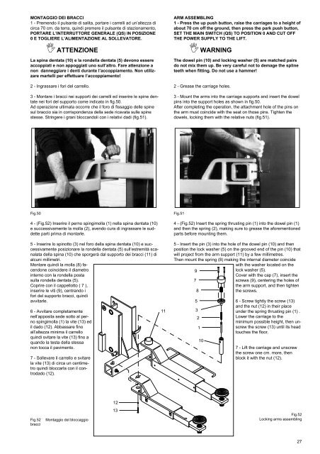
4 - (Fig.52) Inserire il perno spingimolla (1) nella spina <strong>de</strong>ntata (10)<br />
e successivamente la molla (2), avendo cura di ingrassare le sud<strong>de</strong>tte<br />
parti prima di montarle.<br />
5 - Inserire lo spinotto (3) nel foro <strong>de</strong>lla spina <strong>de</strong>ntata (10) e successivamente<br />
posizionare la ron<strong>de</strong>lla <strong>de</strong>ntata (5) sull’estremità scanalata<br />
<strong>de</strong>lla spina (10) che sporgerà dal supporto <strong>de</strong>i bracci (11) di<br />
alcuni millimetri.<br />
Montare quindi la molla (8) facendone<br />
coinci<strong>de</strong>re il diametro<br />
interno con la ron<strong>de</strong>lla posta<br />
sulla ron<strong>de</strong>lla <strong>de</strong>ntata (5).<br />
Coprire con il cappellotto ( 7 ),<br />
inserire le viti (9), centrando i<br />
fori <strong>de</strong>l supporto bracci, quindi<br />
avvitarle.<br />
6 - Avvitare completamente<br />
nell’apposita se<strong>de</strong> sotto al perno<br />
spingimolla (1) la vite (13) ed<br />
il dado (12). Abbassare fino<br />
all’altezza minima il carrello<br />
quindi svitare la vite (13) fino a<br />
quando la testa <strong>de</strong>lla stessa<br />
non tocca il pavimento.<br />
7 - Sollevare il carrello e svitare<br />
la vite (13) di circa un centimetro<br />
quindi bloccarla con il controdado<br />
(12).<br />
11<br />
Fig.51<br />
4 - (Fig.52) Insert the spring thrusting pin (1) into the dowel pin (1)<br />
and then the spring (2), making sure to grease the aforementioned<br />
parts before mounting them.<br />
5 - Insert the pin (3) into the hole of the dowel pin (10) and then<br />
position the lock washer (5) on the grooved end of the pin (10) that<br />
will project from the arm support (11) by a few millimetres.<br />
Then mount the spring (8) making the internal diameter coinci<strong>de</strong><br />
with the washer located on the<br />
9<br />
lock washer (5).<br />
Cover with the cap (7), insert the<br />
7<br />
screws (9), centering the holes of<br />
the arm support, and then tighten<br />
8<br />
the screws.<br />
5<br />
3<br />
2<br />
1<br />
10<br />
6 - Screw tightly the screw (13)<br />
and the nut (12) in their place<br />
un<strong>de</strong>r the spring thrusting pin (1) .<br />
Lower the carriage to the<br />
minimum possible height, then unscrew<br />
the screw (13) until its head<br />
touches the floor.<br />
7 - Lift the carriage and unscrew<br />
the screw one cm. more, then<br />
block it with the nut (12).<br />
12<br />
Fig.52<br />
bracci<br />
Montaggio <strong>de</strong>l bloccaggio<br />
13<br />
Fig.52<br />
Locking arms assembling<br />
27