320I/3.6 - Wertherint.de
320I/3.6 - Wertherint.de
320I/3.6 - Wertherint.de

You also want an ePaper? Increase the reach of your titles
YUMPU automatically turns print PDFs into web optimized ePapers that Google loves.
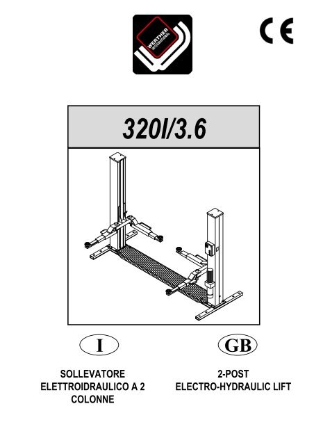
<strong>320I</strong>/<strong>3.6</strong><br />
I<br />
SOLLEVATORE<br />
ELETTROIDRAULICO A 2<br />
COLONNE<br />
GB<br />
2-POST<br />
ELECTRO-HYDRAULIC LIFT
Manuale di istruzioni per l’uso e la manutenzione <strong>de</strong>l<br />
SOLLEVATORE ELETTROIDRAULICO<br />
PER VEICOLI<br />
Mo<strong>de</strong>llo <strong>320I</strong>/<strong>3.6</strong><br />
Instructions and maintenance manual for<br />
ELECTROHYDRAULIC LIFT<br />
FOR VEHICLES<br />
Mo<strong>de</strong>l <strong>320I</strong>/<strong>3.6</strong><br />
Matricola N°<br />
Anno di costruzione<br />
Serial N°<br />
Year of manufacture<br />
COSTRUTTORE:<br />
WERTHER INTERNATIONAL S.p.A.<br />
Se<strong>de</strong> centrale: Via F. BRUNELLESCHI, 12<br />
42040 CADE’ (RE) - ITALY<br />
Telefono ++ / +522 / 9431 (r.a.)<br />
Telefax ++ / +522 / 941997<br />
WEB http://www.wertherint.com<br />
E@MAIL sales@wertherint.com<br />
MANUFACTURER:<br />
WERTHER INTERNATIONAL S.p.A.<br />
Head office: Via F. BRUNELLESCHI, 12<br />
42040 CADE’ (RE) - ITALY<br />
Telephone ++ / +522 / 9431<br />
Telefax ++ / +522 / 941997<br />
WEB http://www.wertherint.com<br />
E@MAIL sales@wertherint.com<br />
1° Emissione - 10 Ottobre 2005<br />
1st Edition - October 10, 2005<br />
CENTRO DI ASSISTENZA<br />
AUTORIZZATO:<br />
AUTHORISED<br />
SERVICE CENTER:<br />
REV.6. . . . . . . . . . . . . . . 23/02/2009<br />
1
Indice<br />
Imballaggio, trasporto<br />
e stoccaggio Pag. 3<br />
Introduzione Pag. 4<br />
Contents<br />
Packing, transport and storage Page 3<br />
Introduction Page 4<br />
Cap.1<br />
Descrizione <strong>de</strong>lla<br />
macchina Pag. 6<br />
Chapter 1<br />
Description<br />
of the machine Page 6<br />
Cap.2 Specifiche tecniche Pag. 8<br />
Chapter 2<br />
Technical<br />
specifications Page 8<br />
Cap.3 Sicurezza Pag.13<br />
Cap.4 Installazione Pag.19<br />
Chapter 3 Safety Page 13<br />
Chapter 4 Installation Page 19<br />
Cap.5 Funzionamento ed uso Pag.31<br />
Chapter 5<br />
Operating principles<br />
and use Page 31<br />
Cap.6 Manutenzione Pag.32<br />
Cap.7 Inconvenienti e rimedi Pag.35<br />
Chapter 6 Maintenance Page 32<br />
Chapter 7 Troubleshooting Page 35<br />
Appendice A<br />
Informazioni<br />
particolari<br />
Pag.36<br />
Appendix A Special notes Page 36<br />
Appendice B Parti di ricambio Pag.36<br />
Appendix B Spare parts Page 36<br />
2
IMBALLAGGIO, TRASPORTO E<br />
STOCCAGGIO<br />
LE OPERAZIONI DI IMBALLAGGIO, SOLLEVAMENTO, MOVI-<br />
MENTAZIONE, TRASPORTO E DISIMBALLO DEVONO ESSE-<br />
RE AFFIDATE ESCLUSIVAMENTE A PERSONALE CHE SIA<br />
ESPERTO IN TALI OPERAZIONI E CHE CONOSCA BENE IL<br />
SOLLEVATORE ED IL PRESENTE MANUALE<br />
IMBALLAGGIO<br />
Il sollevatore viene spedito smontato nei seguenti pezzi:<br />
Peso di un pezzo (Kg)<br />
1 Basamento Kg 150<br />
1 Colonna lato comando completa Kg 270<br />
1 Colonna lato opposto completa Kg 210<br />
2 Bracci lunghi Kg 35<br />
2 Bracci corti Kg 30<br />
1 Pedana di copertura basamento Kg 30<br />
4 Salvapiedi Kg 2<br />
1 Assieme centralina Kg 30<br />
1 Pacco accessori Kg 10<br />
contenente:<br />
Viterie<br />
PACKING, TRANSPORT AND STORAGE<br />
ALL PACKING, LIFTING, HANDLING, TRANSPORT AND<br />
UNPACKING OPERATIONS ARE TO BE PERFORMED<br />
EXCLUSIVELY BY EXPERT PERSONNEL WITH KNOWLEDGE<br />
OF THE LIFT AND THE CONTENTS OF THIS MANUAL<br />
PACKING<br />
The lift is shipped disassembled into the following parts:<br />
Weight (Kg)<br />
1 Base 150 kg<br />
1 Complete command post 270 kg<br />
1 Other si<strong>de</strong> complete post 210 kg<br />
2 Long arms 35 kg<br />
2 Short arms 30 kg<br />
1 Base cover plate 30 kg<br />
4 Foot guard 2 kg<br />
1 Hydraulic power pack 30 kg<br />
1 Accessory package 10 kg<br />
containing:<br />
Nuts and bolts<br />
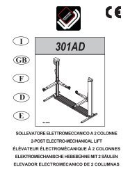
Il sollevatore, ad eccezione <strong>de</strong>l basamento spedito separatamente,<br />
viene inviato in una gabbia di legno (Figura 1) <strong>de</strong>l peso medio di<br />
circa 660 Kg.<br />
SOLLEVAMENTO E MOVIMENTAZIONE<br />
Le gabbie in legno possono essere sollevate e spostate sia con<br />
carrelli elevatori (fig.1) che con gru o carriponte (fig.2). Nel caso di<br />
movimentazione con gru o carriponte, le gabbie <strong>de</strong>vono essere<br />
sempre imbracate con minimo 2 fasce. Il basamento <strong>de</strong>ve essere<br />
movimentato esclusivamente con gru, utilizzando imbracature e<br />
sempre accompagnato da una seconda persona al fine di evitare<br />
oscillazioni pericolose (fig.3).<br />
With the exception of the separate base, the lift is shipped in a<br />
woo<strong>de</strong>n crate (Fig.1), weighing approx. 660 kg.<br />
LIFTING AND HANDLING<br />
The woo<strong>de</strong>n crates may be lifted and moved with a lift truck (Fig.1)<br />
crane or bridge crane (Fig.2). If either of the latter two are used,<br />
crates must be harnessed with at least 2 slings. The base may only<br />
be handled with a crane and appropriate sling, and must always be<br />
accompanied by a second person in or<strong>de</strong>r to avoid dangerous<br />
swinging (fig.3)<br />
Fig.1<br />
Fig.2<br />
I mezzi scelti <strong>de</strong>vono essere<br />
idonei al sollevamento e allo<br />
spostamento in sicurezza, tenendo<br />
conto di dimensioni,<br />
peso, baricentro, sporgenze e<br />
parti <strong>de</strong>licate da non danneggiare.<br />
The equipment chosen must be<br />
suitable for safe lifting and<br />
moving, bearing in mind the<br />
dimensions and weight.<br />
Fig.3<br />
3
STOCCAGGIO<br />
Gli imballi <strong>de</strong>vono sempre essere conservati in luoghi coperti e protetti<br />
a temperature comprese fra -10°C e +40°C. e non <strong>de</strong>vono essere<br />
esposti ai raggi diretti <strong>de</strong>l sole.<br />
IMPILAMENTO DEI PACCHI<br />
Il tipo di imballo previsto preve<strong>de</strong> la possibilità di impilare in magazzino<br />
fino ad 8 gabbie una sull’altra, purchè vengano correttamente<br />
disposte ed assicurate contro la caduta.<br />
Nei cassoni <strong>de</strong>i camion o nei containers si possono impilare fino a<br />
3 gabbie purchè vengano reggiate bene ed assicurate contro la<br />
caduta.<br />
APERTURA DEGLI IMBALLI<br />
All’arrivo verificare che la macchina non abbia subito danni durante<br />
il trasporto e che ci siano tutti i pezzi indicati nella lista di spedizione.<br />
Le gabbie <strong>de</strong>vono essere aperte adottando tutte le precauzioni per<br />
evitare danni alle persone ed ai pezzi <strong>de</strong>lla macchina (evitare cadute<br />
di pezzi dalla gabbia durante l’apertura).<br />
ELIMINAZIONE DELL’IMBALLO<br />
Il legno <strong>de</strong>lla gabbia può essere riutilizzato o riciclato.<br />
STORAGE<br />
Packed machinery mut always be kept in a covered, protected<br />
place, at a temperature between -10° and +40°, and must not be<br />
expesed to direct sunlight.<br />
CRATE STACKING<br />
The type of packing allows the possibility of stacking up to 8<br />
crates.<br />
Up to 3 crates may be stacked one upon the other on lorries or in<br />
containers if properly positioned and provi<strong>de</strong>d they are<br />
restrained to prevent falling.<br />
OPENING THE CRATES<br />
When the crates arrive, check that the machine has not been<br />
damaged during transport and that all parts listed are present.<br />
The crates must be opened using all possible precautionary<br />
measures to avoid damaging the machine or its parts. Make sure<br />
that parts do not fall from the crate during opening.<br />
DISPOSAL OF CRATES<br />
The wood of the crates may be re-used or recycled.<br />
INTRODUZIONE<br />
ATTENZIONE<br />
Questo manuale è stato scritto per il personale di officina ad<strong>de</strong>tto<br />
all’uso <strong>de</strong>l sollevatore (operatore) e per il tecnico ad<strong>de</strong>tto<br />
alla manutenzione ordinaria (manutentore) pertanto, prima<br />
di effettuare qualsiasi operazione sul sollevatore e/o sul suo<br />
imballaggio, occorre leggere attentamente tutto il manuale,<br />
poichè esso contiene informazioni importanti per:<br />
LA SICUREZZA DELLE PERSONE ad<strong>de</strong>tte all’uso ed alla<br />
manutenzione ordinaria,<br />
LA SICUREZZA DEL SOLLEVATORE,<br />
LA SICUREZZA DEI VEICOLI SOLLEVATI.<br />
INTRODUCTION<br />
WARNING<br />
This manual has been prepared for workshop personnel<br />
expert in the use of the lift (operator) and technicians<br />
responsible for routine maintenance (maintenance fitter); read<br />
the manual before carrying out any operation with the lift<br />
and/or the packing. This manual contains important<br />
information regarding:<br />
THE PERSONAL SAFETY of operators and maintenance<br />
workers,<br />
LIFT SAFETY,<br />
THE SAFETY OF LIFTED VEHICLES<br />
CONSERVAZIONE DEL MANUALE<br />
Il manuale è parte integrante <strong>de</strong>l sollevatore e <strong>de</strong>ve sempre accompagnarlo,<br />
anche in caso di vendita.<br />
Esso <strong>de</strong>ve sempre essere conservato in vicinanza <strong>de</strong>l sollevatore,<br />
in luogo facilmente accessibile.<br />
L’operatore ed il manutentore <strong>de</strong>vono poterlo reperire e consultare<br />
rapidamente in qualsiasi momento.<br />
SI RACCOMANDA, IN PARTICOLARE, UNA LETTURA ATTENTA<br />
E RIPETUTA DEL CAPITOLO 3, CHE CONTIENE IMPORTANTI<br />
INFORMAZIONI E AVVISI RELATIVI ALLA SICUREZZA.<br />
Il sollevatore è stato progettato e costruito rispettando quanto segue:<br />
LEGGI:<br />
Direttive europee: 98/37/CE-2004/108/CE-2006/95/CE<br />
NORME TECNICHE:<br />
Norme europee: EN 1493/ EN 292-1/ EN 292-2<br />
IMPIANTO ELETTRICO:<br />
UNI EN 60204, CEI 64/8<br />
CONSERVING THE MANUAL<br />
The manual is an integral part of the lift , which it should<br />
always accompany , even if the unit is sold.<br />
The manual must be kept in the vicinity of the lift, in an easily<br />
accessible place.<br />
The operator and maintenance staff must be able to locate and<br />
consult the manual quickly and at any time.<br />
ATTENTIVE AND REPEATED READING OF CHAPTER 3,<br />
WHICH CONTAINS IMPORTANT INFORMATION AND SAFETY<br />
WARNINGS, IS PARTICULARLY RECOMMENDED.<br />
Lift rack has been <strong>de</strong>signed and built in compliance with the following:<br />
LAWS:<br />
European directives: 98/37/CE-2004/108/CE-2006/95/CE<br />
TECHNICAL STANDARDS:<br />
European standards: EN 1493/ EN 292-1/ EN 292-2<br />
ELECTRICAL SYSTEM:<br />
UNI EN 60204, CEI 64/8<br />
4
Il sollevamento, il trasporto, il disimballo, il montaggio, l’installazione<br />
e la messa in servizio, la taratura e le registrazioni iniziali, la<br />
manutenzione STRAORDINARIA, la riparazione, la revisione, lo<br />
spostamento e lo smantellamento <strong>de</strong>l sollevatore <strong>de</strong>vono essere<br />
eseguiti dai tecnici specializzati <strong>de</strong>i RIVENDITORI AUTORIZZATI<br />
o <strong>de</strong>i CENTRI ASSISTENZA AUTORIZZATI dal Costruttore (ve<strong>de</strong>re<br />
centro assistenza autorizzato indicato nel frontespizio).<br />
Il costruttore non rispon<strong>de</strong> di alcun danno a persone, veicoli od oggetti<br />
causati dagli interventi sopracitati se effettuati da personale<br />
non autorizzato o da un uso improprio o non consentito <strong>de</strong>l sollevatore<br />
Per tutte queste attività vengono indicati, nel presente manuale,<br />
soltanto gli aspetti (operativi e di sicurezza) che possono essere<br />
utili anche all’operatore ed al manutentore per compren<strong>de</strong>re meglio<br />
la struttura ed il funzionamento <strong>de</strong>l sollevatore e per un suo migliore<br />
utilizzo.<br />
Per compren<strong>de</strong>re il linguaggio adottato nel presente manuale, l’operatore<br />
<strong>de</strong>ve posse<strong>de</strong>re esperienza specifica nelle attività di officina,<br />
di assistenza, manutenzione e riparazione <strong>de</strong>i veicoli nonchè la<br />
capacità di interpretare correttamente i disegni e le <strong>de</strong>scrizioni riportate<br />
nel manuale e la conoscenza <strong>de</strong>lle norme antinfortunistiche<br />
generali e specifiche vigenti nel paese in cui viene installato il sollevatore.<br />
Gli stessi criteri valgono per la scelta <strong>de</strong>l tecnico manutentore che<br />
dovrà, inoltre, posse<strong>de</strong>re le conoscenze tecniche specifiche e specialistiche<br />
(meccaniche, elettriche) necessarie per effettuare in sicurezza<br />
gli interventi previsti nel manuale.<br />
Nel testo <strong>de</strong>l manuale troverete spesso le diciture “operatore” e<br />
“manutentore” il cui significato è il seguente:<br />
OPERATORE: persona ad<strong>de</strong>tta all’uso <strong>de</strong>l sollevatore. MANUTEN-<br />
TORE: persona ad<strong>de</strong>tta alla manutenzione ordinaria <strong>de</strong>l sollevatore.<br />
The lifting, transport, unpacking, assembling, installation, starting<br />
up, initial adjustment and testing, EXTRAORDINARY<br />
maintenance, repair, overhauls, transport and dismantling of the lift<br />
must be performed by specialised personnel from the LICENSED<br />
DEALER or an SERVICE CENTRE authorised by the<br />
manufacturer (see authorised <strong>de</strong>aler on frontispiece).<br />
The manufacturer <strong>de</strong>clines all responsibility for injury to persons or<br />
damage to vehicles or objects when any of the above mentioned<br />
operations has been performed by unauthorised personnel or<br />
when the rack has been subject to improper use.<br />
This manual indicates only the operative and safety aspects that<br />
may prove useful to the operator and maintenance worker, in<br />
better un<strong>de</strong>rstanding the structure and operation of the lift and for<br />
best use of the same.<br />
In or<strong>de</strong>r to un<strong>de</strong>rstand the terminology used in this manual, the<br />
operator must have specific experience in workshop, service,<br />
maintenance and repair activities, the ability to interpret correctly<br />
the drawings and <strong>de</strong>scriptions contained in the manual and be<br />
acquainted with the general and specific safety rules relevant to<br />
the country in which the machine has been installed.<br />
The same applies to the maintenance fitter, who must also<br />
possess specific and specialised knowledge (mechanical,<br />
engineering) nee<strong>de</strong>d to perform the operations <strong>de</strong>scribed in the<br />
manual in complete safety.<br />
The words “operator” and “maintenance fitter” used in this<br />
manual are construed as follows:<br />
OPERATOR: person authorised to use the lift<br />
MAINTENANCE FITTER: person authorised for routine<br />
maintenance of the lift.<br />
5
CAP.1. DESCRIZIONE DELLA<br />
MACCHINA<br />
CHAPTER 1<br />
THE MACHINE<br />
DESCRIPTION OF<br />
Il sollevatore elettroidraulico a 2 colonne è fisso, cioè ancorato al<br />
suolo ed è progettato e costruito per il sollevamento e lo stazionamento<br />
in quota di autoveicoli e furgoni.<br />
Il funzionamento è di tipo elettroidraulico.<br />
Il sollevatore è composto, principalmente da :<br />
gruppo struttura fissa ( basamento + colonne)<br />
gruppi mobili ( carrello + bracci )<br />
gruppi di sollevamento;<br />
quadro comando<br />
sicurezze.<br />
In figura 4 sono indicate le varie parti che compongono il sollevatore<br />
e le zone di lavoro consentite e riservate al personale ad<strong>de</strong>tto,<br />
attorno al sollevatore stesso.<br />
Lato comando: è il lato <strong>de</strong>l sollevatore che compren<strong>de</strong> la zona<br />
riservata all’operatore in cui si acce<strong>de</strong> al quadro comandi<br />
Lato servizio: è il lato opposto a quello comando.<br />
Lato anteriore: è il lato braccio lungo.<br />
Lato posteriore: è il lato braccio corto.<br />
The 2-post electro-hydraulic lift, is a fixed installation. This means<br />
that it is anchored to the ground and <strong>de</strong>signed and built for lifting<br />
and positioning automobiles and vans at a certain height off the<br />
ground.<br />
The lift is driven by an electro-hydraulic operating system.<br />
The lift consists of the following main parts:<br />
fixed structure (base + posts);<br />
mobile units (carriage + arms);<br />
lift units;<br />
control box;<br />
safety <strong>de</strong>vices.<br />
Figure 4 illustrates the various parts of the lift and the work areas<br />
reserved for use by operators around the lift.<br />
Command si<strong>de</strong>: this si<strong>de</strong> of the lift inclu<strong>de</strong>s the area reserved for<br />
the operator to access the control box.<br />
Service si<strong>de</strong>: this is the opposite si<strong>de</strong> of the command si<strong>de</strong>.<br />
Front si<strong>de</strong>: the si<strong>de</strong> with the long arm.<br />
Rear si<strong>de</strong>: the si<strong>de</strong> with the short arm.<br />
Lato comando<br />
Command si<strong>de</strong><br />
Lato posteriore<br />
Rear si<strong>de</strong><br />
Lato anteriore<br />
Front si<strong>de</strong><br />
Lato servizio<br />
Service si<strong>de</strong><br />
Fig.4<br />
GRUPPO STRUTTURA FISSA (Fig.5)<br />
E’ costituito da :<br />
Un Basamento (1) costruito in profilati di acciaio saldati, con fori<br />
per il fissaggio al suolo mediante tasselli ad espansione (ve<strong>de</strong>re<br />
cap.4 “Installazione“) e dadi per il fissaggio tramite bullonatura <strong>de</strong>lla<br />
piastra di base <strong>de</strong>lla colonna.<br />
All’interno <strong>de</strong>l basamento scorre una fune di acciaio (2) che trasmette<br />
il moto dalla colonna motore (3) alla colonna servizio (4).<br />
Nella parte superiore <strong>de</strong>l basamento è fissata la pedana (5) di copertura<br />
in lamiera striata.<br />
FIXED STRUCTURE (Fig.5)<br />
This structure consists of:<br />
A base (1) built with wel<strong>de</strong>d steel sections, with holes to connect it<br />
to the ground using expansion bolts (see chapter 4<br />
“Installation) and nuts for bolting the post base plate. A steel cable<br />
(2) runs insi<strong>de</strong> the base transmitting the motion from the motor<br />
post (3) to the service post (4). The chequered plate platform is attached<br />
to the top of the base.<br />
2 Colonne in lamiera di acciaio piegata<br />
alla cui base è saldata una piastra forata<br />
per il fissaggio al basamento mediante<br />
bullonatura.<br />
Alla colonna comando sono fissati il quadro<br />
elettrico di comando e la centralina<br />
idraulica.<br />
All’interno di ogni colonna si trovano i<br />
gruppi mobili di sollevamento <strong>de</strong>ll’automezzo.<br />
4<br />
3<br />
2 Posts built with bent steel plate. The<br />
base is wel<strong>de</strong>d to a drilled<br />
plate to be bolted to the base. The electric<br />
control box and the<br />
hydraulic power unit are attached to the<br />
command post. The vehicle mobile lifting<br />
units are located insi<strong>de</strong> each post.<br />
2<br />
5<br />
Fig.5<br />
Gruppi struttura fissa<br />
1<br />
Fig.5 Fixed structure units<br />
6
GRUPPI DI SOLLEVAMENTO (Fig.6)<br />
Ciascuno è costituito da :<br />
un carrello (1) in lamiera di acciaio saldata, collegato nella parte inferiore,<br />
mediante flange e perni, ai bracci di sollevamento.<br />
Al centro, il carrello è collegato ad una catena (2) che riceve il movimento<br />
dal cilindro idraulico (6) e permette il sollevamento.<br />
Al carrello <strong>de</strong>lla colonna lato comando è collegata la fune (7) che,<br />
mediante un sistema di pulegge (8), trasmette il movimento al carrello<br />
<strong>de</strong>lla colonna lato opposto.<br />
I carrelli sono dotati di rulli di scorrimento e pattini di guida.<br />
Due bracci telescopici di cui uno lungo (3) e uno corto (4), costruiti<br />
in tubolare di acciaio e recanti ad una estremità il piattello (5) regolabile<br />
in altezza per la presa <strong>de</strong>lla macchina e dalla parte opposta il<br />
foro di collegamento con il carrello.<br />
LIFT UNITS (Fig.6)<br />
Each unit consists of:<br />
one carriage (1) built with wel<strong>de</strong>d steel plate, connected at the bottom<br />
to the lift arms by means of flanges and pins. In the<br />
middle, the carriage is connected to a chain (2) that receives the<br />
movement from the hydraulic cylin<strong>de</strong>r (6) and performs the lifting<br />
operation. A cable (7) is connected to the carriage of the<br />
command si<strong>de</strong> post. Through a system of pulleys (8) this cable<br />
transmits the movement to the carriage of the post on the<br />
opposite si<strong>de</strong>. The carriages are equipped with sliding rollers and<br />
gui<strong>de</strong> runners.<br />
Two telescopic arms, one long (3) and one short (4), built with<br />
tubular steel with a pad (5) at each end that can be height<br />
adjusted to hold the car and on the opposite si<strong>de</strong> the carriage connection<br />
hole.<br />
8<br />
2 1<br />
1 3 5 4<br />
6<br />
8<br />
7<br />
8<br />
Fig.6<br />
Gruppo di sollevamento<br />
Fig.6<br />
Lift unit<br />
GRUPPO DI TRASMISSIONE (Fig.6)<br />
La trasmissione viene fornita dalla centralina idraulica che invia olio<br />
sotto pressione al cilindro (6). Questo movimenta un sistema formato<br />
da una catena (2) e da una fune (7) che scorre su pulegge<br />
(8) e manda in movimento sincrono il carrello <strong>de</strong>lla colonna libera.<br />
QUADRO DI COMANDO ( Fig.7)<br />
Sul pannello <strong>de</strong>l quadro elettrico di comando sono installati :<br />
L’interrutore generale (11) - Il pulsante di salita (12) - Il pulsante di<br />
stazionamento (13) - Il pulsante di discesa (14)<br />
TRANSMISSION UNIT (Fig.6)<br />
Transmission is supplied by the hydraulic power unit that sends oil<br />
un<strong>de</strong>r pressure to the cylin<strong>de</strong>r (6). This moves a system consisting<br />
of a chain (2) and a cable (7) that runs on pulleys (8) and times the<br />
movement of the carriage on the free post.<br />
CONTROL BOX (Fig.7)<br />
The panel that houses the electric control box contains the following:<br />
Main switch (11) - Up push button (12) - Parking push button (13) -<br />
Down push button (14)<br />
11<br />
12<br />
15<br />
18<br />
16<br />
13<br />
17<br />
20<br />
14<br />
19<br />
Fig.7<br />
Fig.7<br />
Quadro di comando<br />
Control Box<br />
CENTRALINA IDRAULICA (Fig.8)<br />
La centralina idraulica è composta da un motore elettrico (15), una<br />
pompa idraulica ad ingranaggi (16), un’elettrovalvola di discesa<br />
(17) dotata di un dispositivo di scarico manuale <strong>de</strong>ll’olio (vedi cap.<br />
Uso e Manutenzione), una valvola di massima pressione (18), un<br />
serbatoio olio (19), il tubo di mandata e recupero (20) olio.<br />
N.B.: il tubo di mandata olio può trovarsi in pressione.<br />
Fig.8<br />
Fig.8<br />
Centralina idraulica<br />
Hydraulic power unit<br />
HYDRAULIC POWER UNIT (Fig.8)<br />
The hydraulic power unit consists of an electric motor (15), a<br />
geared hydraulic pump (16), down electro-valve (17) equipped with<br />
a manual oil drain valve (see the Use and Maintenance chapter), a<br />
maximum pressure valve (18), oil reservoir (19) as well as an oil<br />
<strong>de</strong>livery and return pipe (20).<br />
Note: The oil <strong>de</strong>livery pipe may be un<strong>de</strong>r pressure.<br />
7
SICUREZZE<br />
Le sicurezze sono costituite da :<br />
Un sistema di bloccaggio bracci che non permettono movimenti involontari<br />
<strong>de</strong>i bracci <strong>de</strong>l ponte.<br />
4 salvapiedi sui bracci che evitano lo schiacciamento <strong>de</strong>i piedi in<br />
fase di discesa.<br />
Un microinterruttore che interviene in caso di rottura o allungamento<br />
<strong>de</strong>lla fune di trasmissione.<br />
I martelletti di sicurezza sui carrelli che intervengono in fase di stazionamento<br />
<strong>de</strong>l carico in quota ed in caso di rottura <strong>de</strong>lla fune portante.<br />
Un finecorsa di estremità colonna che non permette extracorsa <strong>de</strong>l<br />
cilindro e <strong>de</strong>i carrelli.<br />
Una valvola di blocco in caso di rottura <strong>de</strong>l sistema idraulico.<br />
Le sicurezze elettriche generiche.<br />
Queste sicurezze saranno sviluppate in maggior <strong>de</strong>ttaglio nei seguenti<br />
capitoli.<br />
SAFETY DEVICES<br />
The safety <strong>de</strong>vices inclu<strong>de</strong>:<br />
Arm locking system that prevents acci<strong>de</strong>ntal movements of the<br />
rack arms.<br />
4 foot guards on the arms that prevent feet from being smashed<br />
while the vehicle is <strong>de</strong>scending;<br />
Microswitch that trips when the transmission cables breaks or<br />
stretches.<br />
Safety wedges on the carriages which are activated when the load<br />
is positioned at a certain height off the ground and if the support<br />
cable breaks.<br />
A post end limit switch that does not allow the cylin<strong>de</strong>r and the carriages<br />
to exceed their travel limits.<br />
Lock valve that trips if the hydraulic system ruptures.<br />
General electric safety <strong>de</strong>vices.<br />
These safety <strong>de</strong>vices will be <strong>de</strong>scribed in further <strong>de</strong>tail in the following<br />
chapters.<br />
CAP.2<br />
SPECIFICHE TECNICHE<br />
PORTATA: ................................................3600 Kg (35280 N)<br />
Alt. max. sollevamento auto ......................1920 mm<br />
Alt. min. supporti sollevamento ................. 90 mm<br />
Larg. libera tra colonne .............................2650 mm<br />
Larg. totale ................................................3250 mm<br />
Larg. laterale basamento...........................1500 mm<br />
Lung. massima braccio lungo....................1175 mm<br />
Lung. minima............................................. 730 mm<br />
Lung. massima braccio corto .................... 930 mm<br />
Lung. minima............................................. 500 mm<br />
Tempo di salita.......................................... 45 sec<br />
Tempo di discesa ...................................... 45 sec.<br />
Peso totale <strong>de</strong>l sollevatore ........................circa 630 Kg<br />
Rumorosità................................................
MOTORE ELETTRICO:<br />
ELECTRIC MOTOR<br />
Potenza <strong>de</strong>l motore<br />
elettrico<br />
Trifase<br />
2,2 KW 2,2 KW<br />
Monofase<br />
Tensione 230-400V trif.+/- 5% 230V mono +/- 5%<br />
Frequenza 50 Hz 50 Hz<br />
Assorbimento 230V: 10.7A 15.9A<br />
400V: 6.2A<br />
N° poli 4<br />
Velocità 1400 Giri / 1’ 1380 Giri / 1’<br />
Forma costruttiva<br />
Classe di isolamento F<br />
B14<br />
IP54<br />
Tipo C90 M90 LB4<br />
Electric motor power<br />
rating<br />
Voltage<br />
Three-phase<br />
2,2 KW 2,2 KW<br />
230-400V 3ph.+/-<br />
5%<br />
Frequency 50 Hz 50 Hz<br />
Absorption 230V: 10.7A 15.9A<br />
400V: 6.2A<br />
N° of poles 4<br />
Singlephase<br />
230V 1ph. +/- 5%<br />
Speed 1400 RPM 1380 RPM<br />
Construction size<br />
B14<br />
Insulation class F IP54<br />
Type C90 M90 LB4<br />
Il collegamento <strong>de</strong>l motore <strong>de</strong>ve essere eseguito riferendosi agli<br />
schemi elettrici allegati.<br />
Il senso di rotazione <strong>de</strong>l motore è sinistro (antiorario) come indicato<br />
nella targhetta applicata al motore stesso.<br />
The motor must be connected with reference to the attached<br />
wiring diagrams.<br />
The motor rotates to the left (counterclockwise) as indicated on the<br />
data plate attached to the motor.<br />
POMPA<br />
Tipo ...........................................................18<br />
Mo<strong>de</strong>llo......................................................10A5X348N<br />
Cilindrata ...................................................5 cm3/g<br />
Taratura valvola di massima .....................160 bar<br />
PUMP<br />
Type ..........................................................18<br />
Mo<strong>de</strong>l.........................................................10A5X348N<br />
Size ...........................................................5 cm3/g<br />
Relief valve set-up.....................................160 bar<br />
OLIO<br />
Il serbatoio <strong>de</strong>ll’olio contiene olio idraulico minerale secondo la normativa<br />
ISO/DIN 6743/4 con grado di contaminazione non superiore<br />
alla classe 18/15 secondo la normativa ISO 4406 esempio olio IP<br />
HYDRUS OIL 32; SHELL TELLUS OIL T32 o equivalenti.<br />
OIL<br />
The oil reservoir contains hydraulic mineral oil in accordance with<br />
ISO/DIN 6743/4 with a level of contamination that does not exceed<br />
class 18/15 according to ISO 4406, for example IP HYDRUS OIL<br />
32; SHELL TELLUS OIL T32 or equivalent.<br />
SCHEMA OLEODINAMICO<br />
1<br />
9<br />
HYDRAULIC OIL DIAGRAM<br />
Rif. Descrizione<br />
1 Cilindro<br />
2 Valvola reg. flusso<br />
2<br />
3<br />
Ref.<br />
Description<br />
1 Cylin<strong>de</strong>r<br />
2 Flow control valve<br />
3 Elettrovalvola di scarico<br />
4 Valvola di non ritorno<br />
4<br />
5<br />
3 Drain electro-valve<br />
4 Check valve<br />
5 Valvola di massima<br />
5 Maximum valve<br />
6 Pompa<br />
6 Pump<br />
7 Motore<br />
8 Filtro<br />
7<br />
7 Motor<br />
8 Filter<br />
9 Valvola di blocco<br />
9 Lock valve<br />
10 Serbatoio<br />
6<br />
8<br />
10 Reservoir<br />
10<br />
Fig.10<br />
Schema oleodinamico<br />
Fig. 10 Hydraulic oil diagram<br />
9
SCHEMI ELETTRICI<br />
Schema elettrico TRIFASE<br />
WIRING DIAGRAMS<br />
THREE-PHASE wiring diagram.<br />
Rif.<br />
Ref.<br />
Descrizione<br />
Description<br />
Marca<br />
Brand<br />
Articolo<br />
Article<br />
C1 ELM Elettromagnete Electromagnet WARNER EL. TT6-1 24V 50Hz 1<br />
C3 ELV Elettrovalvola Electro-valve OIL SISTEM 24VAC 50/60Hz ED100% 1<br />
FU1-FU2 F1-F2 Portafusibili Fuse carrier WEBER PCH10x38 + CH10x38 3<br />
PTC F3 Limitatore di temperatura Temperature limiter Integrato nel motore / Integrate in the motor 1<br />
QM1 FC1 Microinterruttore sensore fune Cable sensor microswitch PIZZATO FR1454 1<br />
QM5 FC2 Fine corsa salita Ascent limit switch PIZZATO FR654 1<br />
QS IG Interruttore generale Master switch SPRECHER LA2-16-1753+LFS2-N-6-175 1<br />
+LA2-12-C4<br />
KM1 K1 Teleruttore Contactor 24V 50/60Hz 1<br />
M M Motore elettrico Electric motor 230V/400V 50Hz 1<br />
SB1 P1 Pulsante salita Lifting push buttons 1 NO 1<br />
SB2 P2 Pulsante discesa Lowering push buttons 2 NO 1<br />
SB3 P3 Pulsante stazionamento Parking push button 1 NO 1<br />
TM TR Trasformatore Transformer C.E. 230-400/24V 75A 50/60Hz 1<br />
VV VV Connessione Faston Faston connection<br />
Morsetti Terminals CABUR CBD2 2.5mmq 3<br />
Morsetti Terminals CABUR TE4/D-TE4/0 4mmq 1<br />
Q.tà<br />
Q.ty<br />
10
Schema elettrico MONOFASE<br />
SINGLE-PHASE wiring diagram.<br />
Rif.<br />
Ref.<br />
Descrizione<br />
Description<br />
Marca<br />
Brand<br />
Articolo<br />
Article<br />
C1 ELM Elettromagnete Electromagnet WARNER EL. TT6-1 24V 50Hz 1<br />
C3 ELV Elettrovalvola Electro-valve OIL SISTEM 24VAC 50/60Hz ED100% 1<br />
FU1-FU2 F1-F2 Portafusibili Fuse carrier WEBER PCH10x38 + CH10x38 3<br />
QM1 FC1 Microinterruttore sensore fune Cable sensor microswitch PIZZATO FR1454 1<br />
QM5 FC2 Fine corsa salita Ascent limit switch PIZZATO FR654 1<br />
QS IG Interruttore generale Master switch SPRECHER LA2-16-1753+LFS2-N-6-175 1<br />
+LA2-12-C4<br />
KM1 K1 Teleruttore Contactor 24V 50/60Hz 1<br />
M M Motore elettrico Electric motor 230V 50Hz 1<br />
SB1 P1 Pulsante salita Lifting push buttons 1 NO 1<br />
SB2 P2 Pulsante discesa Lowering push buttons 2 NO 1<br />
SB3 P3 Pulsante stazionamento Parking push button 1 NO 1<br />
TM TR Trasformatore Transformer C.E. 230/24V 75A 50/60Hz 1<br />
VV VV Connessione Faston Faston connection<br />
Morsetti Terminals CABUR CBD2 2.5mmq 2<br />
Morsetti Terminals CABUR TE4/D-TE4/0 4mmq 1<br />
Q.tà<br />
Q.ty<br />
11
TIPI DI VEICOLI SOLLEVABILI E INGOMBRI<br />
Il sollevatore si adatta praticamente a tutti i veicoli di peso non superiore<br />
a 3600 Kg e le cui dimensioni non eccedano quelle riportate<br />
di seguito.<br />
DIMENSIONI MASSIME DEI VEICOLI DA SOLLEVARE<br />
La larghezza non <strong>de</strong>ve ecce<strong>de</strong>re i 2200 mm.<br />
Il passo tra gli assi non <strong>de</strong>ve ecce<strong>de</strong>re i 3000 mm.<br />
L’altezza minima da terra può interferire con le strutture <strong>de</strong>l sollevatore.<br />
Fare attenzione soprattutto alle autovetture sportive.<br />
Eventuali carrozzati speciali possono essere sollevati tenendo però<br />
conto <strong>de</strong>lla portata <strong>de</strong>l sollevatore.<br />
Anche la zona di rischio per le persone dovrà essere a<strong>de</strong>guata<br />
alle dimensioni speciali <strong>de</strong>l veicolo.<br />
Gli schemi seguenti riportano i criteri per <strong>de</strong>finire i limiti di impiego<br />
<strong>de</strong>l sollevatore.<br />
VEHICLE WEIGHT AND SIZE<br />
Lift rack can be adapted to virtually all vehicles no<br />
heavier than 3600 kg, the dimensions of which do not exceed the<br />
following.<br />
MAXIMUM DIMENSIONS OF VEHICLES TO BE LIFTED<br />
Max. width: 2200 mm.<br />
Max. wheelbase: 3000 mm.<br />
The un<strong>de</strong>rbody of cars with low ground clearance may interfere<br />
with the structure of the lift. Pay particular attention in the case of<br />
low body sports cars.<br />
Always keep the capacity of the lift in mind in the case of vehicles<br />
with particular characteristics.<br />
The danger zone will be <strong>de</strong>termined by the dimensions of the<br />
vehicle.<br />
The diagrams below inclu<strong>de</strong> the criteria for <strong>de</strong>fining the limits of<br />
use of the car rack.<br />
C<br />
B<br />
A<br />
Min.(mm)<br />
A - 2200<br />
B - 3000<br />
C 150 -<br />
Max.(mm)<br />
Fig.13<br />
Misure minime e massime<br />
PER INGOMBRI MAGGIORI VERIFICARE IL CARICO MASSIMO<br />
E LO SBILANCIAMENTO DEL CARICO.<br />
Fig.13<br />
Minimum and maximum dimensions<br />
CHECK MAXIMUM LOAD CAPACITY AND LOAD<br />
DISTRIBUTION IN CASE OF LARGER VEHICLES.<br />
PESI MASSIMI DEI VEICOLI DA SOLLEVARE<br />
MAXIMUM WEIGHT OF THE VEHICLE TO BE LIFT<br />
2400 1200 1200 2400<br />
MAX.3600 Kg.!<br />
Fig.14<br />
12<br />
Distribuzione <strong>de</strong>i pesi<br />
Fig.14<br />
Weight distribution
CAP.3<br />
SICUREZZA<br />
CHAPTER 3<br />
SAFETY<br />
É estremamente importante leggere questo capitolo attentamente<br />
ed in ogni sua parte poichè contiene importanti informazioni<br />
sui rischi che operatore e manutentore possono correre<br />
in caso di un uso errato <strong>de</strong>l ponte sollevatore.<br />
Nel testo che segue troverete chiare spiegazioni su alcune situazioni<br />
di rischio o pericolo che si possono verificare durante<br />
l’uso e la manutenzione <strong>de</strong>l sollevatore, sui dispositivi di sicurezza<br />
adottati e sul loro uso corretto, sui rischi residui e sui<br />
comportamenti da tenere (precauzioni generali e specifiche<br />
per eliminarli o neutralizzarli).<br />
ATTENZIONE:<br />
Il sollevatore è stato progettato e costruito per il sollevamento<br />
e lo stazionamento in quota <strong>de</strong>i veicoli in ambiente chiuso.<br />
Ogni altro uso non è consentito ed in particolare esso non è<br />
idoneo per operazioni di:<br />
- lavaggio e verniciatura;<br />
- ponteggio o sollevamento di persone;<br />
- pressa per schiacciare;<br />
- montacarichi;<br />
- CRIC per sollevare o cambiare ruote.<br />
Il costruttore non rispon<strong>de</strong> di alcun danno a persone, veicoli<br />
od oggetti causati dall’uso improprio o non consentito <strong>de</strong>i sollevatori.<br />
É estremamente importante che in fase di salita o discesa l’operatore<br />
agisca soltanto dalla postazione di comando indicata in fig.15.<br />
É vietato a chiunque sostare entro la zona di rischio indicata in<br />
fig.15.<br />
In fase di lavoro la presenza di persone sotto il veicolo è ammessa<br />
soltanto quando il veicolo è già sollevato.<br />
ATTENZIONE:<br />
LA PRESENZA DI PERSONE SOTTO IL VEICOLO SOLLEVATO<br />
E’ AMMESSA SOLTANTO QUANDO IL SOLLEVATORE E’ IN<br />
STAZIONAMENTO SUI MARTELLETTI DI SICUREZZA.<br />
NON UTILIZZARE LA MACCHINA SENZA LE PROTEZIONI O<br />
CON LE PROTEZIONI DISATTIVATE.<br />
IL MANCATO RISPETTO DI QUESTE NORME PUO’ RECARE<br />
GRAVI DANNI ALLE PERSONE, AL SOLLEVATORE ED AI VEI-<br />
COLI SOLLEVATI.<br />
It is vital to read this chapter of the manual carefully and from<br />
beginning to end as it contains important information<br />
regarding the risks that the operator or maintenance fitter may<br />
be exposed to in the eventuality that the lift is used<br />
incorrectly.<br />
The following text contains clear explanations regarding<br />
certain situations of risk or danger that may arise during the<br />
operation or maintenance of the lift, the safety <strong>de</strong>vices<br />
installed and the correct use of such systems, residual risks<br />
and operative procedures to use (general and specific precautions<br />
to eliminate potential hazards).<br />
WARNING:<br />
Lift is <strong>de</strong>signed and built to lift vehicles and hold them in the<br />
elevated position in a closed workshop. All other uses are<br />
unauthorised. In particular, the lift is not suitable for:<br />
- washing and respray work;<br />
- creating raised platforms or lifting personnel;<br />
- use as a makeshift press for crushing purposes;<br />
- use as goods lift;<br />
- use as a jack for lifting vehicles or changing wheels.<br />
The manufacturer disclaims all liability for injury to persons or<br />
damage to vehicles and other property caused by the<br />
incorrect and unauthorised use of the lift.<br />
During lift and <strong>de</strong>scent movements, the operator must remain in<br />
the command station as <strong>de</strong>fined in figure 15. The presence of<br />
persons insi<strong>de</strong> the danger zone indicated in the same figure is<br />
strictly prohibited. The presence of persons beneath the vehicle<br />
during operations is permitted only when the vehicle is parked in<br />
the elevated position.<br />
WARNING:<br />
THE PRESENCE OF PERSONS BENEATH THE VEHICLE IS<br />
PERMITTED ONLY WHEN THE LIFT IS IN THE PARKING<br />
POSITION ON THE SAFETY WEDGES.<br />
DO NOT USE THE LIFT WITHOUT PROTECTION DEVICES OR<br />
WITH THE PROTECTION DEVICES INHIBITED.<br />
FAILURE TO COMPLY WITH THESE REGULATIONS CAN<br />
CAUSE SERIOUS INJURY TO PERSONS, AND IRREPERABLE<br />
DAMAGE TO THE LIFT AND THE VEHICLE BEING LIFTED.<br />
Zona di rischio<br />
Danger zone<br />
Fig.15<br />
Zone di lavoro<br />
Zona operatore<br />
Operator zone<br />
Fig.15<br />
Working areas<br />
13
PRECAUZIONI GENERALI<br />
L’operatore ed il manutentore sono tenuti al rispetto <strong>de</strong>lle prescrizioni<br />
contenute in leggi e norme antinfortunistiche vigenti nel paese<br />
in cui è installato il sollevatore.<br />
Devono inoltre:<br />
operare sempre dalle postazioni di lavoro previste ed indicate nel<br />
manuale;<br />
non rimuovere nè disattivare i carter e le protezioni meccaniche,<br />
elettriche, o di altra natura;<br />
prestare attenzione agli avvisi di sicurezza riportati nelle targhette<br />
applicate sulla macchina e nel manuale.<br />
Nel testo <strong>de</strong>l manuale gli avvisi di sicurezza saranno evi<strong>de</strong>nziati<br />
nelle forme seguenti:<br />
PERICOLO: Indica un pericolo imminente che può causare danno<br />
alle persone (gravi lesioni o anche la morte).<br />
ATTENZIONE: Indica situazioni e/o comportamenti rischiosi che<br />
possono causare danni alle persone (lesioni più o meno gravi e/o<br />
anche la morte).<br />
CAUTELA: Indica situazioni e/o comportamenti rischiosi che possono<br />
causare danni di minore gravità alle persone e/o danni al sollevatore,<br />
al veicolo o ad altre cose.<br />
RISCHIO DI FOLGORAZIONE: è un particolare avviso di sicurezza<br />
che viene riportato sul sollevatore, tramite targhetta, in alcuni<br />
punti dove è particolarmente elevato il rischio di forti scosse elettriche.<br />
GENERAL PRECAUTIONS<br />
The operator and the maintenance fitter are required to observe<br />
the prescriptions of acci<strong>de</strong>nt prevention legislation in force in the<br />
country of installation of the lift.<br />
Furthermore, the operator and maintenance fitter must:<br />
Always work in the scheduled working area as shown in the<br />
manual.<br />
never remove or <strong>de</strong>activate the guards and mechanical,<br />
electrical, or other types of safety <strong>de</strong>vices;<br />
read the safety notices affixed to the machine and the safety<br />
information in this manual.<br />
In the manual all safety notices are shown as follows:<br />
DANGER: Indicates imminent danger that can result in serious<br />
injury or <strong>de</strong>ath.<br />
WARNING: Indicates situations and/or types of manoeuvres that<br />
are unsafe and can cause injuries of various <strong>de</strong>grees or <strong>de</strong>ath.<br />
CAUTION: Indicates situations and/or types of manoeuvres that<br />
are unsafe and can cause minor injury to persons and/or damage<br />
the lift, the vehicle or other property.<br />
RISK OF ELECTRIC SHOCK: specific safety notice affixed to the<br />
lift in areas where the risk of electric shock is particularly high.<br />
RISCHI E PROTEZIONI<br />
Vediamo ora quali rischi possono correre gli operatori o il manutentore<br />
nelle fasi d’uso <strong>de</strong>l sollevatore e quali protezioni sono state<br />
adottate dal costruttore per ridurre al minimo tali rischi:<br />
SPOSTAMENTI LONGITUDINALI E LATERALI<br />
Gli spostamenti longitudinali sono i movimenti in avanti o all’indietro<br />
<strong>de</strong>l carico.<br />
Gli spostamenti laterali sono i movimenti verso <strong>de</strong>stra o verso sinistra<br />
che il veicolo può avere, specialmente durante la fase di salita<br />
sul sollevatore.<br />
Essi sono evitabili posizionando in maniera corretta i piattelli <strong>de</strong>i<br />
bracci appoggiandoli nei punti di presa consentiti <strong>de</strong>lla vettura e regolando<br />
alla stessa altezza (avvitando o svitando) i piattelli stessi.<br />
Lo spostamento <strong>de</strong>ll’automezzo sui bracci, la regolazione <strong>de</strong>i<br />
bracci e <strong>de</strong>i piattelli <strong>de</strong>ve essere fatto esclusivamente a bracci<br />
totalmente abbassati cioè con i piattelli liberi da qualunque<br />
contatto con il mezzo.<br />
RISKS AND PROTECION DEVICES<br />
We shall now examine the risks to which operators or maintenance<br />
fitters may be exposed when the vehicle is immobilised in the<br />
raised position, together with the protection <strong>de</strong>vices adopted by the<br />
manufacturer to reduce all such hazards to the minimum:<br />
LONGITUDINAL AND LATERAL MOVEMENT<br />
Longitudinal movement is consi<strong>de</strong>red the backward and forward<br />
shifting of the load.<br />
Lateral movement implies the shifting to the left or right of the<br />
vehicle, especially during the lifting phase on the rack.<br />
These movements can be avoi<strong>de</strong>d by positioning the vehicle<br />
correctly on the arm disk support plates, which must be previously<br />
adjusted to the same height (by loosening or tightening) as the<br />
vehicle.<br />
Do not move the vehicle in relation to the arms or adjust arms<br />
and disk support plates until the arms have been totally<br />
lowered, i.e. the disk support plates must be free from all contact<br />
with the vehicle.<br />
Fig.16<br />
Riscio di caduta <strong>de</strong>l veicolo<br />
Fig.16<br />
Risk of vehicle fall<br />
ATTENZIONE<br />
NON TENTARE DI SPOSTARE IL MEZZO QUANDO I PIATTEL-<br />
LI DI APPOGGIO SONO GIÀ A CONTATTO CON QUESTO.<br />
WARNING<br />
DO NOT ATTEMPT TO MOVE THE VEHICLE WHEN IT IS<br />
RESTING ON THE DISK SUPPORT PLATES.<br />
14
É estremamente importante posizionare il mezzo sul sollevatore in<br />
modo da avere una corretta ripartizione <strong>de</strong>i pesi sui bracci (fig.17)<br />
Per la sicurezza <strong>de</strong>lle persone e <strong>de</strong>i mezzi è importante che:<br />
si rispetti la zona di rischio durante il sollevamento (fig.15)<br />
il motore sia spento,la marcia innestata ed il freno a mano tirato.<br />
il veicolo sia posizionato in maniera corretta (fig.17)<br />
vengano sollevati soltanto i veicoli ammessi (fig.13-14) senza superare<br />
portata ed ingombri previsti.<br />
It is very important to position the vehicle on the lift so that the<br />
weight is correctly distributed on the arms (fig.17).<br />
To ensure the safety of persons and equipment, it is important that:<br />
people rest outsi<strong>de</strong> the danger zone while the vehicle raising<br />
(fig.15)<br />
the engine is off, the clutch engaged and the parking brake<br />
pulled.<br />
that vehicle is correctly positioned (fig.17)<br />
only authorised vehicles (fig.13-14) are raised without exceeding<br />
the rated capacity and overall dimensions.<br />
Fig.17<br />
Veicolo caricato<br />
correttamente<br />
Fig.17<br />
Correctly loa<strong>de</strong>d vehicle<br />
RISCHI IN FASE DI<br />
SOLLEVAMENTO DEL<br />
VEICOLO<br />
Contro i sovraccarichi in<br />
peso e contro eventuali<br />
rotture sono stati adottati<br />
i seguenti dispositivi di sicurezza:<br />
in caso di sovraccarico<br />
sul motore interviene il<br />
relè termico nel quadro elettrico.<br />
In caso di sovraccarico <strong>de</strong>l sollevatore interviene la valvola di massima<br />
pressione ( fig.18) posta sulla centralina oleodinamica.<br />
in caso di rottura <strong>de</strong>l sistema idraulico (centralina/tubi) interviene la<br />
valvola di blocco (19, fig.19) posta sul cilindro<br />
in caso di allentamento e/o rottura <strong>de</strong>lla fune di acciaio di trasmissione<br />
interviene il microinterruttore fune posto nel basamento che<br />
interrompe l’alimentazione al quadro elettrico: il ponte rimane stazionato<br />
in sicurezza mediante i martelletti posti all’interno <strong>de</strong>i carrelli.<br />
in caso di extra corsa <strong>de</strong>lla parte mobile è stato previsto un finecorsa<br />
elettrico nella parte superiore <strong>de</strong>lla colonna comando; in caso di<br />
mancato funzionamento <strong>de</strong>l finecorsa, dopo circa 30 millimetri di<br />
ulteriore salita il cilindro arriva a fine corsa quindi interviene la valvola<br />
di massima pressione sulla centralina.<br />
in caso di eccessiva corsa <strong>de</strong>l cilindro è anche stato inserito un<br />
connettore a strappo (20, fig.19) che interrompe l’alimentazione al<br />
quadro.<br />
RISKS WHILE THE<br />
VEHICLE IS BEING<br />
RAISED<br />
The following safety <strong>de</strong>vices<br />
have been installed to protect<br />
against overweight conditions<br />
and equipment failure:<br />
the thermal relay in the<br />
electric box will trip if the<br />
motor is verloa<strong>de</strong>d.<br />
The maximum pressure valve (18, fig.18), located on the hydraulic<br />
oil power unit, will trip if the lift is overloa<strong>de</strong>d.<br />
the block valve (19, fig.19), located on the cylin<strong>de</strong>r, will trip if the<br />
hydraulic system ruptures (power unit/hoses)<br />
the cable microswitch located in the base will trip if the steel<br />
transmission cable stretches and/or breaks. This cuts off the<br />
power supply to the electric box: the rack remains in the safety position<br />
as a result of the action of the wedges located insi<strong>de</strong> the carriages.<br />
if the mobile part exceeds its rated travel distance, an electric<br />
limit switch in the top of the command post will trip. If the limit<br />
switch fails, after rising about 30 millimetres, the cylin<strong>de</strong>r<br />
reaches the limit and then the maximum pressure valve on the<br />
power unit trips.s<br />
if the cylin<strong>de</strong>r exceeds its travel distance, a pull connector has<br />
been installed which cuts off the power supply to the control box<br />
(20, fig.19).<br />
20<br />
19<br />
Fig.19<br />
Fig.18<br />
1 Valvola di ritegno Check valve<br />
2 Elettrovalvola Solenoid valve<br />
3 Scarico manuale Manual outlet<br />
4 Carico olio Delivery<br />
5 Tubo per recupero olio Drain hose<br />
6 Valvola regolatrice di scarico Outlet adjusting valve<br />
7 Valvola massima pressione Relief valve<br />
15
RISCHI DIRETTI ALLE PERSONE<br />
In questo paragrafo verranno illustrati i rischi che operatore, manutentore<br />
e chi si trova nell’area di lavoro <strong>de</strong>l sollevatore, possono<br />
correre a causa di un uso non corretto <strong>de</strong>l sollevatore stesso.<br />
RISKS TO PERSONS<br />
This paragraph illustrates risks to which the operator, maintenance<br />
worker or any person near the operating area of the lift may be<br />
exposed in the case of improper use of equipment.<br />
RISCHIO DI SCHIACCIAMENTO<br />
DELL’OPERATORE<br />
dovuto ad una errata posizione<br />
<strong>de</strong>ll’operatore ad<strong>de</strong>tto al quadro comandi.<br />
Durante la fase di discesa <strong>de</strong>lle pedane<br />
e <strong>de</strong>l veicolo l’operatore non<br />
<strong>de</strong>ve mai portarsi sotto le parti mobili<br />
in fase di discesa ma operare<br />
soltanto dalla zona comando<br />
(fig.20).<br />
RISK OF CRUSHING (OPERATOR)<br />
Possible if the operator controlling the<br />
lift is not in the specified position at the<br />
command<br />
panel. When the platforms and vehicle<br />
are<br />
<strong>de</strong>scending, the operator must never<br />
be partly or completely un<strong>de</strong>rneath the<br />
moving<br />
structure. During this phase the operator<br />
must remain in the command zone<br />
fig.20).<br />
Fig.20 Rischio di schiacciamento<br />
<strong>de</strong>ll’operatore<br />
Fig.20<br />
Operator crushing risk<br />
RISCHIO DI SCHIACCIAMENTO<br />
DEL PERSONALE IN GENERE<br />
Durante la fase di discesa <strong>de</strong>l sollevatore<br />
e <strong>de</strong>l veicolo il personale<br />
non <strong>de</strong>ve sostare in zone interessate<br />
dalle traiettorie di discesa<br />
(fig.21). L’operatore <strong>de</strong>ve manovrare<br />
solo dopo essersi accertato che<br />
nessuna persona sia in posizioni<br />
pericolose.<br />
RISK OF CRUSHING (PERSONNEL)<br />
When the platforms and vehicle are<br />
<strong>de</strong>scending personnel are prohibited<br />
from entering the area beneath the moving<br />
parts of the lift (fig.21). The lift<br />
operator must not start the manoeuvre<br />
until it has been clearly<br />
established that there are no persons<br />
in potentially dangerous positions.<br />
Fig.21 Rischio di schiacciamento <strong>de</strong>l<br />
personale in genere<br />
Fig.21<br />
Generic people crushing risk<br />
RISCHIO DI URTO<br />
Dovuto alle parti <strong>de</strong>l sollevatore o<br />
<strong>de</strong>l veicolo posizionate ad altezza<br />
d’uomo.<br />
Quando, per ragioni di lavoro, il sollevatore<br />
viene fermato a quote relativamente<br />
basse (inferiori a 1,75 m<br />
dal suolo) vi è il rischio di urtare<br />
contro le parti non evi<strong>de</strong>nziate da<br />
particolari colorazioni (Fig.22).<br />
RISK OF IMPACT<br />
Caused by parts of the lift or the vehicle<br />
that are positioned at head height.<br />
When, due to operational reasons, the<br />
lift is immobilised at relatively low elevations<br />
(less than 1.75 m from the<br />
ground) personnel must be careful to<br />
avoid impact with parts of the machine<br />
not marked with special hazard<br />
colouring (Fig.22).<br />
Fig.22<br />
Rischio di urto<br />
Fig.22<br />
Impact risk<br />
RISCHIO DI SPOSTAMENTO<br />
DEL VEICOLO<br />
Dovuto ad operazioni da compiere<br />
e che generano spinte sul veicolo<br />
(fig.23).<br />
Se il veicolo é di dimensioni o pesi<br />
ragguar<strong>de</strong>voli uno spostamento<br />
può rappresentare una situazione<br />
di sovraccarico o sbilanciamento<br />
non previsto pertanto evitare in<br />
maniera assoluta tali manovre.<br />
RISKS DUE TO VEHICLE MOVEMENT<br />
Movement may be caused during operations<br />
which involve force sufficient to<br />
move the bvehicle (Fig.23).<br />
If the vehicle is of consi<strong>de</strong>rable dimensions<br />
or weight, movement may lead to<br />
overloading or unbalancing; all measures<br />
must be taken to avoid such an occurrence.<br />
Fig.23<br />
veicolo<br />
Rischio di spostamento <strong>de</strong>l<br />
Fig.23<br />
Vehicle movement risk<br />
16
RISCHIO DI CADUTA DEL<br />
VEICOLO DAL SOLLEVATORE.<br />
Che può essere causato dal posizionamento<br />
non corretto <strong>de</strong>l veicolo sui<br />
piattelli <strong>de</strong>i bracci, da un posizionamento<br />
non corretto <strong>de</strong>l veicolo rispetto<br />
al sollevatore (fig.24) o da dimensioni<br />
<strong>de</strong>l veicolo non compatibili con<br />
lo stesso sollevatore.<br />
RISK OF VEHICLE FALLING FROM<br />
LIFT<br />
This risk could be caused by the<br />
incorrect positioning of the vehicle on<br />
the arm disk support plates (fig.24) or<br />
incorrect positioning of the arm disk<br />
support plates in relation to the lift.<br />
Fig.24<br />
Rischio di caduta <strong>de</strong>l veicolo<br />
Fig.24<br />
Risk of vehicle fall<br />
E’ VIETATO SALIRE SUL VEICOLO E/O METTERLO IN MOTO<br />
CON IL SOLLEVATORE INNALZATO (fig.25).<br />
NEVER BOARD THE VEHICLE AND/OR TURN THE ENGINE ON<br />
WHEN LIFT IS RAISED (fig.25).<br />
Fig.25<br />
NON LASCIARE OGGETTI APPOGGIATI ALLE COLONNE O<br />
NELLA ZONA DI DISCESA DELLE PARTI MOBILI in quanto si<br />
può avere il blocco <strong>de</strong>lla discesa,o la caduta <strong>de</strong>l veicolo<br />
(fig.26).<br />
NEVER LEAN OBJECTS AGAINST THE POSTS OR LEAVE<br />
THEM IN THE AREA WHERE MOVING PARTS ARE LOWERED;<br />
this could hamper lowering or cause the vehicle to fall from<br />
the rack (fig.26).<br />
Fig.26<br />
RISCHIO DI SCIVOLAMENTO<br />
Dovuto a zone <strong>de</strong>l pavimento sporche di lubrificanti (fig.27).<br />
SLIPPING<br />
This risk may arise due to spillage of lubricants in the surrounding<br />
area (fig.27).<br />
TENERE PULITA LA ZONA SOT-<br />
TO E VICINA AL SOLLEVATORE<br />
pulendo le MACCHIE D’OLIO.<br />
Al fine di evitare il rischio di scivolamento<br />
utilizzare i mezzi individuali<br />
previsti (scarpe antinfortunistiche).<br />
ALWAYS KEEP THE AREA<br />
SURROUNDING THE LIFT CLEAN<br />
by removing all OIL SPILLS.<br />
To avoid the risk of slipping, make use<br />
of the recommen<strong>de</strong>d personal protection<br />
(anti-slip footwear).<br />
Fig.27<br />
Rischio di scivolamento<br />
Fig.27<br />
Skidding risk<br />
17
RISCHIO DI FOLGORAZIONE<br />
Accanto a parti <strong>de</strong>l sollevatore in cui<br />
si trovano fili elettrici evitate getti<br />
d’acqua, di vapore (da pulitrice a vapore),<br />
di solventi o vernici nella zona<br />
<strong>de</strong>l sollevatore ed in particolar modo<br />
nelle immediate vicinanze <strong>de</strong>l quadro<br />
elettrico (fig.28).<br />
L’utilizzo di acqua nelle vicinanze <strong>de</strong>l<br />
sollevatore è previsto solo per la versione<br />
per uso esterno.<br />
RISK OF ELECTRIC SHOCK<br />
Risk of electric shock in areas of the<br />
lift housing electrical wiring.<br />
Do not use jets of water, steam (high<br />
pressure wash units), solvents or<br />
paint in the immediate vicinity of the<br />
lift, and take special care to keep<br />
such substances clear of the electrical<br />
command panel (fig.28).<br />
The use of water near the lift is<br />
acceptable only in the case lift has<br />
been manufactured for external<br />
installation.<br />
Fig.28<br />
Rischio di folgorazione<br />
Fig.28<br />
Electrocaution risk<br />
RISCHIO DA ILLUMINAZIONE NON IDONEA<br />
L’operatore ed il manutentore <strong>de</strong>vono verificare che tutte le zone<br />
<strong>de</strong>l sollevatore siano sempre illuminate in maniera uniforme ed in<br />
conformità a quanto previsto dalla normativa vigente nel luogo di<br />
installazione.<br />
RISCHIO DI ROTTURE DI COMPONENTI DURANTE IL<br />
FUNZIONAMENTO<br />
Il costruttore ha utilizzato materiali e procedure progettuali e costruttive<br />
idonee all’uso previsto e atte a creare un’apparecchiatura<br />
affidabile e sicura ma è necessario rispettare l’uso per cui è stato<br />
progettato il sollevatore nonchè le frequenze <strong>de</strong>lle ispezioni e <strong>de</strong>lle<br />
manutenzioni consigliate nel capitolo 6 “MANUTENZIONE”.<br />
RISKS RELATED TO INAPPROPRIATE LIGHTING.<br />
The operator and the maintenance fitter must be able to assure<br />
that all the areas of the lift are properly and uniformly illuminated in<br />
compliance with the laws in force in the place of installation.<br />
RISK OF COMPONENT FAILURE DURING OPERATION.<br />
The manufacturer has used appropriate materials and<br />
construction techniques in relation to the specified use of the<br />
machine in or<strong>de</strong>r to manufacture a reliable and safe lift. Note<br />
however, that the lift must be used in conformity with<br />
manufacturer’s prescriptions and the frequency of inspections and<br />
maintenance work recommen<strong>de</strong>d in chapter 6 “MAINTENANCE”<br />
must be observed.<br />
RISCHI PER USI NON<br />
CONSENTITI<br />
Non é ammessa la presenza di persone<br />
sulle pedane nè durante il sollevamento<br />
nè quando il veicolo è<br />
gia’ sollevato (fig.29).<br />
RISKS RELATED TO IMPROPER<br />
USE<br />
Persons are not permitted to stand or<br />
sit on the platforms during the lift<br />
manoeuvre or when the vehicle is<br />
already lifted (fig.29).<br />
Fig.29<br />
Ogni uso <strong>de</strong>l sollevatore, diverso da quello per cui è stato progettato<br />
può creare inci<strong>de</strong>nti, anche molto gravi, alle persone<br />
che stanno lavorando nelle immediate vicinanze.<br />
É pertanto estremamente importante attenersi scrupolosamente a<br />
tutte le regole riguardanti l’uso, la manutenzione e la sicurezza riportate<br />
in questo manuale.<br />
All uses of the lift other than the uses for which it was<br />
<strong>de</strong>signed are liable to give rise to serious acci<strong>de</strong>nts involving<br />
the persons working in the immediate vicinity of the unit.<br />
It is therefore essential to adhere scrupulously to all regulations<br />
regarding use, maintenance and safety contained in this manual.<br />
Portata<br />
Capacity<br />
Matricola<br />
Serial number<br />
Dati motore<br />
Motor data<br />
Fig.30: avvisi di sicurezza e<br />
targhette applicati sulla macchina.<br />
Fig.30: Safety notices and<br />
data plates affixed to the<br />
machine<br />
18
CAP.4<br />
INSTALLAZIONE<br />
CHAPTER 4<br />
INSTALLATION<br />
QUESTE OPERAZIONI SONO DI COMPETENZA ESCLUSIVA<br />
DEI TECNICI SPECIALIZZATI INCARICATI DAL COSTRUTTO-<br />
RE O DAI RIVENDITORI AUTORIZZATI .<br />
SE EFFETTUATE DA ALTRE PERSONE POSSONO CREARE<br />
SITUAZIONI DI PERICOLO E CAUSARE GRAVI DANNI ALLE<br />
PERSONE E/O AL SOLLEVATORE.<br />
VERIFICA DEI REQUISITI PER L’INSTALLAZIONE<br />
Il sollevatore è costruito per l’impiego in locali chiusi e riparati. Il<br />
luogo prescelto non <strong>de</strong>ve essere vicino a lavaggi, a posti di verniciatura,<br />
a <strong>de</strong>positi di solventi o vernici, a locali con lavorazioni che<br />
possono creare atmosfere esplosive.<br />
VERIFICA DI IDONEITÀ DELLE DIMENSIONI DEL LOCALE E<br />
DELLE DISTANZE DI SICUREZZA.<br />
Il sollevatore <strong>de</strong>ve essere installato rispettando le distanze di sicurezza<br />
da muri,colonne, altre macchine, ecc... come indicate in<br />
Fig.31 e secondo le eventuali prescrizioni <strong>de</strong>lla legislazione vigente<br />
nel luogo di installazione.<br />
Verificare in particolare:<br />
altezza: minimo 5000 mm (consi<strong>de</strong>rare l’altezza <strong>de</strong>i veicoli da sollevare<br />
tenendo conto che l’altezza max. <strong>de</strong>i bracci è di circa 2000<br />
mm.).<br />
distanza dai muri: minimo 700 mm,<br />
spazi per lavorare: minimo 800 mm, oltre le dimensioni <strong>de</strong>l veicolo<br />
da sollevare.<br />
spazi per la POSTAZIONE DI COMANDO,<br />
spazi per la manutenzione, per accessi e vie di fuga in caso di<br />
emergenze.<br />
posizione relativa alle altre macchine,<br />
possibilità di realizzare l’allacciamento elettrico.<br />
THE FOLLOWING OPERATIONS MUST BE PERFORMED<br />
EXCLUSIVELY BY SPECIALISED TECHNICAL STAFF WITH<br />
AUTHORISATION FROM THE MANUFACTURER OR LICENSED<br />
DEALER.<br />
IF THESE OPERATIONS ARE PERFORMED BY OTHER<br />
PERSONS , SERIOUS PERSONAL INJURY AND/OR<br />
IRREPERABLE DAMAGE TO THE LIFT UNIT MAY RESULT.<br />
INSTALLATION REQUISITE CHECKLIST<br />
The lift is <strong>de</strong>signed for installation in enclosed areas suitably<br />
protected from the weather. The place of installation must be well<br />
clear of areas <strong>de</strong>stined to washing or painting, and away from<br />
solvent or paint storage areas or areas where there is a risk of<br />
potentially explosive atmosphere.<br />
SUITABILITY OF THE DIMENSIONS OF THE PLACE OF<br />
INSTALLATION AND SAFETY CLEARANCES.<br />
The lift must be installed in observance of the clearances between<br />
walls, pillars, other machines, etc. indicated in Figure 31 and in<br />
compliance with any legislative requirements in the country of<br />
installation.<br />
Check in particular:<br />
minimum height: 5000 mm inclusive of height of vehicle and maximum<br />
height of arms, i.e. 2000 mm.<br />
minimum distance from walls: 700 mm,<br />
minimum working area: 800 mm,<br />
area for COMMAND STATION,<br />
area for maintenance, access and emergency escape routes.<br />
position in relation to other machines,<br />
proximity to power supply for trouble-free hook-up.<br />
Nel caso di officine con più<br />
sollevatori, la loro disposizione dovrà<br />
essere <strong>de</strong>finita e <strong>de</strong>ttagliata in base<br />
alle norme di lavoro e di sicurezza.<br />
If in a garage several hoists are installed,<br />
their emplacement has to be carried<br />
out according to the relevant labour<br />
safety rules.<br />
Fig.31<br />
Distanze di sicurezza<br />
Fig.31<br />
Safety distances<br />
ILLUMINAZIONE<br />
Tutte le zone <strong>de</strong>lla macchina <strong>de</strong>vono essere illuminate in modo<br />
uniforme e sufficiente per garantire le operazioni di regolazione e<br />
manutenzione previste nel manuale, evitando zone d’ombra, riflessi,<br />
abbagliamento e affaticamento <strong>de</strong>lla vista.<br />
L’illuminazione <strong>de</strong>ve essere realizzata in accordo con la normativa<br />
vigente nel luogo di installazione (a cura <strong>de</strong>ll’installatore <strong>de</strong>ll’impianto<br />
di illuminazione).<br />
LIGHTNING<br />
All parts of the machine must be uniformly lit with sufficient light to<br />
assure that the adjustment and maintenance operations specified<br />
in the manual can be performed, and without areas of shadow, reflected<br />
light, glare and avoiding all situations that could give rise to<br />
eye fatigue.<br />
The lighting must be installed in accordance with the laws in force<br />
in the place of installation (responsibility lies with the lighting<br />
equip-ment fitter).<br />
19
PAVIMENTO<br />
Il sollevatore <strong>de</strong>ve essere installato su platea<br />
orizzontale di spessore minimo 150 mm<br />
realizzata in calcestruzzo dosato con resistenza<br />
>25 N/mm2.<br />
Il pavimento <strong>de</strong>ve inoltre essere piano e<br />
ben livellato (10 mm di tolleranza sul livellamento).<br />
Nel caso di applicazioni particolari, interpellare<br />
il costruttore.<br />
FLOOR<br />
The lift must be installed on a<br />
horizontal concrete bed with a<br />
minimum thickness of 150 mm built and a resistance<br />
>25 N/mm2.<br />
The floor must also be flat and level (10 mm<br />
of tolerance for levelling).<br />
Consult the manufacturer with regard to special<br />
applications.<br />
MONTAGGIO<br />
FIg.32<br />
Spessore <strong>de</strong>l pavimento<br />
ATTENZIONE<br />
DURANTE IL MONTAGGIO NON É AMMESSO<br />
NESSUN ESTRANEO AI LAVORI<br />
MONTAGGIO BASAMENTO<br />
1 - Togliere dal basamento la pedana di copertura, svitando le<br />
quattro viti che la bloccano.<br />
2 - Togliere i bulloni di fissaggio colonne già avvitati sul basamento.<br />
3 - Posizionare il basamento nella zona prestabilita per l’installazio-ne<br />
(fig.33).<br />
ASSEMBLING<br />
Fig.32<br />
Floor thickness<br />
WARNING<br />
DURING INSTALLATION ONLY AUTHORISED<br />
PERSONNEL IS ALLOWED<br />
BASE ASSEMBLING<br />
1 - Remove the cover plate from the base, loosening the four<br />
screws that hold it in position.<br />
2 - Remove the post connection bolts already screwed into the<br />
base.<br />
3 - Position the base in<br />
the installation area<br />
(fig.33).<br />
Fig.33<br />
4 - Montare il microinterruttore fune nel basamento posizionandolo<br />
come indicato in fig.34 e serrandolo mediante le viti TCEI M5x30<br />
fornite ; collegare il cavo come indicato in figura 34a.<br />
4 - Mount the cable microswitch in the base, positioning it as<br />
shown in fig.34 and tightening it using the screws supplied (hex.<br />
socket head cap screw M5x30);connect the cable as picture 34a..<br />
11-12 Contatto rapido Giallo-Nero<br />
21-22 Contatto ritardato Blu-Marrone<br />
S Asta sensore<br />
T Braccio microinterruttore<br />
V<br />
A<br />
B<br />
Vite per la regolazione <strong>de</strong>l braccio microinterruttore<br />
Campo di azione per fune allentata,interrompe solo la<br />
discesa<br />
Campo di azione per fune rotta,interrompe anche la<br />
salita<br />
11-12 Quick contact Yellow-Black<br />
21-22 Retar<strong>de</strong>d contact Blue-Brown<br />
S Sensor rod<br />
T Microswitch arm<br />
V<br />
A<br />
B<br />
Screw for the microswitch arm adjustement<br />
Cable loose action range,interrupt the <strong>de</strong>scent<br />
Cable broken action range,interrupt the rise<br />
Fig.34a<br />
Fig.34<br />
Fig.34<br />
Montaggio <strong>de</strong>l finecorsa<br />
Assembling the limit switch<br />
20
MONTAGGIO COLONNE<br />
1 - Posizionare la colonna comando sul basamento come indicato<br />
in Fig.35 ed inserire 2 bulloni senza serrare (Fig.36).<br />
ATTENZIONE:<br />
durante questa operazione è indispensabile fare attenzione a<br />
non schiacciare la fune di acciaio ed il cavetto <strong>de</strong>l microinterruttore<br />
fra la piastra <strong>de</strong>lla colonna ed il basamento. Per evitare<br />
danni a fune e cavetto si <strong>de</strong>vono tenere tirati mentre si posizio-na<br />
la colonna.<br />
POST ASSEMBLING<br />
1 - Position the command post on the base as shown in Fig.35 and<br />
insert 2 bolts without tightening them (Fig.36).<br />
WARNING:<br />
While doing this operation be very careful not to crush the<br />
steel cable and the microswitch wire between the post plate<br />
and the base. Damage can be avoi<strong>de</strong>d by keeping the cable<br />
and the wire taut while positioning the post.<br />
Fig.36<br />
Fig.36<br />
Fissaggio provvisorio <strong>de</strong>lla colonna.<br />
Temporary post connection<br />
Fig.35<br />
2 - posizionare la colonna libera sdraiata a terra vicina al basamento<br />
come indicato in fig.37.<br />
3 - Nella colonna libera svitare le viti TE M8x16 <strong>de</strong>lla lama fermaperno<br />
come indicato in fig.38, sfilare il perno <strong>de</strong>lla puleggia e togliere<br />
la puleggia dalla se<strong>de</strong> (fig.39).<br />
2 - position the free post laying on the ground close to the base as<br />
shown in fig.37.<br />
3 - Loosen the screws (HH M8x16) of the pin stopping plate into<br />
the free post, as shown in fig.38, pulling out the pulley pin and<br />
removing the pulley from its seat (fig.39).<br />
Fig.37<br />
Fig.37<br />
Posizionamento <strong>de</strong>lla seconda colonna<br />
Positioning the second post<br />
Fig.38<br />
Fig.38<br />
Smontaggio <strong>de</strong>lla puleggia<br />
Pulley <strong>de</strong>mounting<br />
21
4-Sten<strong>de</strong>re la fune di acciaio che esce dalla colonna comando per<br />
tutta la lunghezza <strong>de</strong>l basamento ed inserirne il codulo filettato<br />
nell’asola <strong>de</strong>lla colonna libera, facendolo passare sopra al perno<br />
antiscarrucolamento (fig.40).<br />
4 - Extend the steel cable that comes out of the command post<br />
along the entire length of the base and insert the threa<strong>de</strong>d end into<br />
the slot of the free post, passing it above the no-slip pin (fig.40).<br />
Fig.40<br />
Fig.40<br />
Inserimento <strong>de</strong>l codulo filettato<br />
Inserting the threa<strong>de</strong>d end<br />
Fig.39<br />
5 - Rimontare la puleggia nella sua se<strong>de</strong>, tenendo la fune di acciaio<br />
nella gola <strong>de</strong>lla puleggia. Inserire il perno e la lama fermaperno tolta<br />
in prece<strong>de</strong>nza e fissarla con le relative viti.<br />
6 - Togliere il carter in testa alla colonna libera; rimuovere le lame<br />
fermaperno puleggia a forma di “L” quindi far passare il codulo <strong>de</strong>lla<br />
fune di acciaio fra la puleggia e la schiena <strong>de</strong>lla colonna, tenendo<br />
la fune nella gola <strong>de</strong>lla puleggia (fig.41).<br />
7 - Tenere in tensione la fune di acciaio <strong>de</strong>ntro alla gola <strong>de</strong>lla puleggia<br />
quindi rimontare le lame fermaperno a “L” serrandole con i<br />
relativi bulloni (fig.42).<br />
8 - Rimontare il carter in testa alla colonna libera.<br />
5 - Replace the pulley, keeping the steel cable in the pulley race.<br />
Insert the pin and the pin stopping plate that was previously removed<br />
and connect it with the relative screws.<br />
6 - Remove the casing at the top of the free post; remove the<br />
“L”-shaped pulley pin stopping plate and pass the end of the steel<br />
cable between the pulley and the back of the post, keeping the<br />
cable in the pulley race (fig.41).<br />
7 - Keep the steel cable un<strong>de</strong>r tension insi<strong>de</strong> the pulley race and<br />
then replace the “L”-shaped pin stopping plates tightening them<br />
with the relative bolts (fig.42).<br />
8 - Replace the casing at the top of the free post.<br />
Fig.41<br />
Fig.42<br />
22
9 - Tenendo tirata la fune di acciaio sollevare la colonna libera ed<br />
inserire 2 bulloni nei fori <strong>de</strong>lla piastra colonna, avvitandoli senza<br />
serrare.<br />
ATTENZIONE<br />
Durante questa operazione è indispensabile stare attenti a non<br />
schiacciare la fune di acciaio fra la piastra <strong>de</strong>lla colonna e il<br />
basamento (fig.35).<br />
NOTA: durante il sollevamento <strong>de</strong>lla colonna il carrello non<br />
ca<strong>de</strong> poichè è fissato dal martelletto di sicurezza.<br />
9 - Keeping the steel cable taut, lift the free post and insert the 2<br />
bolts into the holds on the post plate, screwing them in without<br />
tightening.<br />
WARNING<br />
While doing this operation be very careful not to crush the<br />
steel cable between the post plate and the base (Fig.35).<br />
NOTE: when lifting the post, the carriage will not fall since it is<br />
connected by the safety wedge.<br />
10 - Inserire il codulo filettato <strong>de</strong>lla fune di acciaio nel foro <strong>de</strong>l carrello<br />
<strong>de</strong>lla colonna libera quindi bloccarlo mediante i due dadi M20<br />
(dado e controdado) e la relativa ron<strong>de</strong>lla (fig.43).<br />
10 - Insert the threa<strong>de</strong>d end of the steel cable into the hole of the<br />
carriage of the free post and then lock it into position using the two<br />
nuts M20 (nut and counternut) and the relative washer (fig.43).<br />
Fig.43<br />
Fig.44<br />
Fig.44<br />
Montaggio <strong>de</strong>lla centralina oleodinamica<br />
Hydraulic oil unit assembling<br />
ATTENZIONE<br />
WARNING<br />
prima <strong>de</strong>l serraggio <strong>de</strong>l codulo con dado e controdado, verificare<br />
che la fune passi nelle gole <strong>de</strong>lle pulegge <strong>de</strong>lle colonne e<br />
nella gola <strong>de</strong>lla puleggia che aziona il microinterruttore di sicurezza<br />
(fig.34).<br />
11 - Inserire i restanti bulloni TE M16x40 e le relative ron<strong>de</strong>lle tra<br />
colonna e basamento serrandole con coppia di serraggio pari a<br />
168 N/m.<br />
before tightening the end with the nut and counternut, make<br />
sure that the cable passes in the pulley races of the posts and<br />
in the pulley race that activates the safety microswitch (fig.34).<br />
11 - Insert the remaining bolts (HH M16x40) and the relative<br />
washers between the post and the base, tightening them with a torque<br />
of 168 N/m.<br />
MONTAGGIO DELLA CENTRALINA IDRAULICA<br />
1 - Fissare la centralina idraulica alla colonna comando come indicato<br />
in fig.44 con le viti TE M8x16 e le ron<strong>de</strong>lle Ø8.<br />
HYDRAULIC OIL UNIT ASSEMBLING<br />
1 - Attach the hydraulic oil unit to the command post as shown in<br />
fig.44 using the screws HH M8x16 and the washers Ø8.<br />
23
ALLACCIAMENTO IMPIANTO IDRAULICO<br />
1 - Collegare il tubo in gomma alta pressione attaccato al cilindro,<br />
alla pompa <strong>de</strong>lla centralina come indicato in fig.45.<br />
ATTENZIONE<br />
Tenere fermo il particolare 1 Fig.45 con una chiave (2 Fig.45a).<br />
HYDRAULIC PLANT CONNECTION<br />
1 - Connect the high-pressure rubber hose attached to the cylin<strong>de</strong>r<br />
to the power unit pump, as shown in fig.45.<br />
WARNING<br />
Keep the <strong>de</strong>tail 1 Fig.45 locked using a wrench (2 Fig.45a).<br />
2<br />
1<br />
Fig.45a<br />
Fig.45<br />
Fig.45<br />
Collegamento idraulico <strong>de</strong>l cilindro<br />
Cylin<strong>de</strong>r hydraulic connection<br />
2 - Togliere il tappo di carico olio e sostituirlo con il tappo di sfiato<br />
fornito (rif.1, fig.46).<br />
2 - Remove the oil filler plug and replace it with the supplied breather<br />
cap (ref. 1, fig.46).<br />
1<br />
Fig.46<br />
Sostituzione <strong>de</strong>l tappo per lo sfiato<br />
Fig.46<br />
Replacing the plug with the breather cap<br />
24
ALLACCIAMENTO IMPIANTO ELETTRICO<br />
ATTENZIONE<br />
Le operazioni sottoelencate <strong>de</strong>vono essere eseguite<br />
da personale qualificato.<br />
1) Prima <strong>de</strong>l collegamento elettrico verificare che :<br />
l’impianto di alimentazione al sollevatore sia dotato <strong>de</strong>lle prote-zioni<br />
previste dalle norme vigenti nel paese in cui viene installato.<br />
la linea di alimentazione abbia la seguente sezione :<br />
Tensione sollevatore 400V trifase:.......................minimo 2,5 mm2<br />
Tensione sollevatore 230V trifase:.......................minimo 4 mm2<br />
Tensione sollevatore 230V monofase:.................minimo 6 mm2<br />
le oscillazioni di tensione rientrino nel campo di tolleranza previsto<br />
dalle specifiche.<br />
2) Eseguire l’allacciamento di potenza e di comando alla morsettiera<br />
<strong>de</strong>l quadro come indicato in fig.47 rif. “A”, inserendo il cavo nella<br />
cassetta passando dal foro predisposto e seguendo lo schema<br />
<strong>de</strong>ll’impianto elettrico come nelle pagine 10 o 11.<br />
Il costruttore fornisce il ponte predisposto per il funzionamento<br />
a 400V trifase; nel caso la tensione di linea sia diversa, diventa<br />
necessario cambiare il collegamento <strong>de</strong>l motore e <strong>de</strong>l<br />
trasformatore (Fig.48).<br />
ELECTRIC PLANT CONNECTION<br />
WARNING<br />
The operations listed below must be performed<br />
by skilled personnel.<br />
1) Before connecting the electric system, make sure that:<br />
the power supply plant to the lift is equipped with the protection <strong>de</strong>vices<br />
required by current standards in the country where the machinery<br />
is installed.<br />
the power supply line has the following cross-section:<br />
Lift voltage 400V, three-phase.........................:minimum 2.5 mm2<br />
Lift voltage 230V, three-phase: ...........................minimum 4 mm2<br />
Lift voltage 230V, single-phase:...........................minimum 6 mm2<br />
the voltage oscillations are within the tolerance range set forth by<br />
the specifications.<br />
2) Connect the power and control system to the terminal strip on<br />
the control box as shown in fig.47 ref. “A”, inserting the cable into<br />
the rack passing through the prepared hole and following the wiring<br />
diagram on pages 10 or 11.<br />
The manufacturer supplies the rack to operate at 400V with a<br />
three-phase configuration; if the line voltage is different, the<br />
motor and transformer connection must be changed (Fig.48).<br />
“A”<br />
Sensore fune - Cable sensor<br />
Elettromagnete - Electromagnet<br />
Finecorsa di salita - Lift limit switch<br />
Elettrovalvola - Solenoid valve<br />
Motore - Motor<br />
Fig.47<br />
Collegamenti elettrici <strong>de</strong>l quadro<br />
Fig.47<br />
Control box electric connections<br />
25
2 - Eseguire i collegamenti elettrici ai morsetti <strong>de</strong>l motore:<br />
2-1 Aprire la scatola contatti posta sul motore ed effettuare<br />
i collegamenti come indicato in fig.48, a seconda <strong>de</strong>lla<br />
tensione acui verrà alimentato il ponte.<br />
Collegare la protezione termica (Rif. 8-9 Fig. 38).<br />
ATTENZIONE<br />
Il costruttore fornisce il ponte predisposto per il funzionamento<br />
a 400V trifase. Nel caso la tensione di linea sia di 230V trifase,<br />
occorre, oltre a collegare diversamente i contatti nella morsettiera<br />
sul motore, occorre cambiare il collegamento sul trasformatore<br />
(ve<strong>de</strong>re morsettiera sul trasformatore stesso).<br />
2 - Complete the electrical connections to the motor terminals:<br />
2-1 Open the box of contacts located on the motor and<br />
connect them as shown in fig.48, according to the voltage<br />
at which the rack will be fed.<br />
Connected the temperature protection (Ref. 8-9 Fig. 38).<br />
WARNING<br />
The manufacturer supplies the rack to operate at 400V with a<br />
three-phase configuration. If the line voltage is 230V,<br />
three-phase, the contacts on the motor terminal strip and the<br />
transformer must be connected differently.<br />
400V<br />
230V<br />
Fig.48<br />
Collegamenti motore e trasformatore<br />
Fig.48<br />
Motor and transformer connections<br />
3) Chiu<strong>de</strong>re il coperchio <strong>de</strong>l quadro elettrico, ruotare l’interrutore<br />
generale (QS, Fig.49) in posizione 1, premere il pulsante di salita<br />
(rif.SB1, Fig.49) se il senso di rotazione non corrispon<strong>de</strong> con quello<br />
<strong>de</strong>lla freccia, invertire tra loro 2 fasi <strong>de</strong>ll’alimentazione.<br />
4) Controllare il corretto funzionamento<br />
<strong>de</strong>i finecorsa di estremità colonna<br />
premendoli manualmente.<br />
QS<br />
3) Close the cover of the electric box, turn the main switch (QS,<br />
Fig.49) to position 1, press the up push button (ref. SB1, Fig.49)<br />
and, if the direction of rotation does not correspond to that shown<br />
by the arrow, reverse the 2 power supply phases.<br />
4) Make sure that the post end limit<br />
switches work properly by<br />
pressing them manually.<br />
SB1<br />
Fig.49<br />
26
MONTAGGIO DEI BRACCI<br />
1 - Premendo il pulsante di salita, portare i carrelli ad un’altezza di<br />
circa 70 cm. da terra, quindi premere il pulsante di stazionamento,<br />
PORTARE L’INTERRUTTORE GENERALE (QS) IN POSIZIONE<br />
0 E TOGLIERE L’ALIMENTAZIONE AL SOLLEVATORE.<br />
ATTENZIONE<br />
La spina <strong>de</strong>ntata (10) e la ron<strong>de</strong>lla <strong>de</strong>ntata (5) <strong>de</strong>vono essere<br />
accoppiati e non appoggiati uno sull’altro. Fare attenzione a<br />
non danneggiare i <strong>de</strong>nti durante l’accoppiamento. Non utilizzare<br />
martelli per effettuare l’accoppiamento!<br />
2 - Ingrassare i fori <strong>de</strong>l carrello.<br />
3 - Montare i bracci nei supporti <strong>de</strong>i carrelli ed inserire le spine <strong>de</strong>ntate<br />
nei fori <strong>de</strong>l supporto come indicato in fig.50.<br />
Ad operazione ultimata occorre che il foro di fissaggio <strong>de</strong>lle spine<br />
sul braccio sia in corrispon<strong>de</strong>nza <strong>de</strong>lla se<strong>de</strong> ricavata sulle spine<br />
stesse. Stringere i grani bloccandoli con i relativi dadi (fig.51).<br />
ARM ASSEMBLING<br />
1 - Press the up push button, raise the carriages to a height of<br />
about 70 cm off the ground, then press the park push button,<br />
SET THE MAIN SWITCH (QS) TO POSITION 0 AND CUT OFF<br />
THE POWER SUPPLY TO THE LIFT.<br />
WARNING<br />
The dowel pin (10) and locking washer (5) are matched pairs<br />
do not mix them up. Be very careful not to <strong>de</strong>mage the spline<br />
teeth when fitting. Do not use a hammer!<br />
2 - Grease the carriage holes.<br />
3 - Mount the arms into the carriage supports and insert the dowel<br />
pins into the support holes as shown in fig.50.<br />
After completing the operation, the attachment hole of the pins on<br />
the arm must coinci<strong>de</strong> with the seat on those pins. Tighten the<br />
dowels, locking them with the relative nuts (fig.51).<br />
Fig.50<br />
4 - (Fig.52) Inserire il perno spingimolla (1) nella spina <strong>de</strong>ntata (10)<br />
e successivamente la molla (2), avendo cura di ingrassare le sud<strong>de</strong>tte<br />
parti prima di montarle.<br />
5 - Inserire lo spinotto (3) nel foro <strong>de</strong>lla spina <strong>de</strong>ntata (10) e successivamente<br />
posizionare la ron<strong>de</strong>lla <strong>de</strong>ntata (5) sull’estremità scanalata<br />
<strong>de</strong>lla spina (10) che sporgerà dal supporto <strong>de</strong>i bracci (11) di<br />
alcuni millimetri.<br />
Montare quindi la molla (8) facendone<br />
coinci<strong>de</strong>re il diametro<br />
interno con la ron<strong>de</strong>lla posta<br />
sulla ron<strong>de</strong>lla <strong>de</strong>ntata (5).<br />
Coprire con il cappellotto ( 7 ),<br />
inserire le viti (9), centrando i<br />
fori <strong>de</strong>l supporto bracci, quindi<br />
avvitarle.<br />
6 - Avvitare completamente<br />
nell’apposita se<strong>de</strong> sotto al perno<br />
spingimolla (1) la vite (13) ed<br />
il dado (12). Abbassare fino<br />
all’altezza minima il carrello<br />
quindi svitare la vite (13) fino a<br />
quando la testa <strong>de</strong>lla stessa<br />
non tocca il pavimento.<br />
7 - Sollevare il carrello e svitare<br />
la vite (13) di circa un centimetro<br />
quindi bloccarla con il controdado<br />
(12).<br />
11<br />
Fig.51<br />
4 - (Fig.52) Insert the spring thrusting pin (1) into the dowel pin (1)<br />
and then the spring (2), making sure to grease the aforementioned<br />
parts before mounting them.<br />
5 - Insert the pin (3) into the hole of the dowel pin (10) and then<br />
position the lock washer (5) on the grooved end of the pin (10) that<br />
will project from the arm support (11) by a few millimetres.<br />
Then mount the spring (8) making the internal diameter coinci<strong>de</strong><br />
with the washer located on the<br />
9<br />
lock washer (5).<br />
Cover with the cap (7), insert the<br />
7<br />
screws (9), centering the holes of<br />
the arm support, and then tighten<br />
8<br />
the screws.<br />
5<br />
3<br />
2<br />
1<br />
10<br />
6 - Screw tightly the screw (13)<br />
and the nut (12) in their place<br />
un<strong>de</strong>r the spring thrusting pin (1) .<br />
Lower the carriage to the<br />
minimum possible height, then unscrew<br />
the screw (13) until its head<br />
touches the floor.<br />
7 - Lift the carriage and unscrew<br />
the screw one cm. more, then<br />
block it with the nut (12).<br />
12<br />
Fig.52<br />
bracci<br />
Montaggio <strong>de</strong>l bloccaggio<br />
13<br />
Fig.52<br />
Locking arms assembling<br />
27
8 - Verificare il corretto funzionamento <strong>de</strong>l dispositivo di bloccaggio<br />
bracci, premendo verso l’alto la vite (13) sotto al perno spingimolla<br />
(1) e ruotando il braccio in uno <strong>de</strong>i 2 sensi, così che dopo una breve<br />
rotazione il perno ritorni nella sua posizione (Fig.53).<br />
8 - Make sure that the arm locking <strong>de</strong>vice works correctly, pressing<br />
the spring thrusting pin (1) upwards and turning the arm in one of<br />
the 2 directions, so that after a brief rotation the pin returns to its<br />
position (Fig.53).<br />
2<br />
3<br />
1<br />
Fig.53<br />
La stessa verifica <strong>de</strong>ve essere fatta abbassando completamente il<br />
carrello e verificando che il braccio si sblocchi.<br />
9 - Ripetere le stesse operazioni per il montaggio <strong>de</strong>gli altri 3 bracci.<br />
10 - Montare sui bracci i parapiedi di sicurezza (1 e 2, Fig.54),<br />
usando le viti TE M10x10 e le relative ron<strong>de</strong>lle (3).<br />
ATTENZIONE<br />
Controllare il corretto funzionamento <strong>de</strong>i blocca bracci in tutte<br />
le posizioni possibili per il sollevamento di un veicolo.<br />
Fig.54<br />
Make sure that the arm locking <strong>de</strong>vice works correctly, also by<br />
pulling completely down the carriage, then check the armdoes not<br />
remain blocked.<br />
9 - Repeat the same operations for assembling the other 3 arms.<br />
10 - Mount the foot guards on the arms (1 and 2, Fig.54), using the<br />
screws HH M10x10 and the relative washers (3).<br />
WARNING<br />
Make sure the arms lock in all the positions where they might<br />
lift a vehicle.<br />
Fig.55<br />
Marca<br />
Brand<br />
Tipo<br />
Typ<br />
HILTI HB M12/25/L 20 85<br />
FISCHER FH18x100 18 100<br />
A<br />
B<br />
Fig.56<br />
REGISTRAZIONE E BLOCCAGGIO DEL SOLLEVATORE<br />
1 - Forare il pavimento con una punta elicoidale da calcestruzzo,<br />
usando come dima di foratura le asole nel basamento raccomandiamo:<br />
(fig. 55 e 56).<br />
2 - Inserire il tassello completamente nel pavimento e, prima <strong>de</strong>l<br />
serraggio, verificare la perpendicolarità<br />
in entrambi gli assi <strong>de</strong>lle colonne, spessorando<br />
dove necessario con lamierini di<br />
dimensione di circa 80 x 80 mm.<br />
3 - Serrare con chiave dinamometrica i<br />
tasselli di fissaggio <strong>de</strong>l basamento, con<br />
una coppia di serraggio di 70 Nm<br />
(Fig.57).<br />
LIFT ADJUSTMENT AND LOCKING<br />
1 - Drill into the floor using the slots, on the base-plate as a template<br />
we recommend (figures 55 and 56).<br />
2 - Insert the screw anchor into the floor; before fitting, check that<br />
the posts are perpendicular to the floor. If not, use 80 x 80 mm<br />
sheet metal shims to compensate.<br />
3 - Use a torque wrench to tighten the<br />
anchor bolts in the base to a torque<br />
setting of 70 Nm (Fig.57).<br />
Fig.57<br />
28
4 - Agendo sul dado <strong>de</strong>l codulo fune<br />
<strong>de</strong>l carrello lato opposto (fig.43), regolare<br />
l’altezza <strong>de</strong>l carrello stesso in<br />
modo che risulti 10 mm. più alto <strong>de</strong>l<br />
carrello lato comando (fig.58); questo<br />
al fine di compensare l’allungamento<br />
<strong>de</strong>lla fune sotto carico. Quindi<br />
bloccare il codulo fune sul carrello<br />
lato opposto serrando l’apposito<br />
controdado.<br />
4- Using the nut of the opposite si<strong>de</strong><br />
carriage cable end (fig.43), adjust the<br />
height of the carriage so that it is 10<br />
mm higher than the carriage on the<br />
command si<strong>de</strong> (fig.58). This<br />
compensates for the elongation of the<br />
cable un<strong>de</strong>r load. Then lock the cable<br />
end on the opposite carriage si<strong>de</strong> by<br />
tightening the special counternut.<br />
Fig.58<br />
Regolazione <strong>de</strong>i carrelli<br />
Fig.58<br />
Carriage adjustment<br />
5 - Il costruttore fornisce il ponte con i martelletti di sicurezza pretarati.<br />
Verificare comunque con un calibro che la distanza fra i martelletti<br />
di sicurezza e le aste forate sia di 5mm come indicato in<br />
fig.59. Se la distanza non risultasse essere tale, agire sui dadi di<br />
regolazione (A e B, fig.59) fino a portarla al valore richiesto.<br />
5 - The manufacturer supplies the rack with the safety wedges<br />
pre-calibrated. In any case, use a gauge to check that the distance<br />
between the safety wedges and the drilled rods is 5 mm as shown<br />
in fig.59. If the distance is not correct, use the adjustment nuts (A<br />
and B, fig.59) to obtain the required value.<br />
B<br />
A<br />
Fig.59<br />
Regolazione <strong>de</strong>i martelletti<br />
Fig.59<br />
safety wedges adjustment<br />
6 -Verificare che alla massima altezza la distanza tra i martelletti (1<br />
Fig. 59A) e le asole (2 Fig. 59A) <strong>de</strong>ll’asta di sicurezza sulle 2 colonne<br />
sia 20 mm minimo dal suo appoggio, una misura inferirore<br />
non darebbe il tempo alla sicurezza di ruotare rimanendo agganciata<br />
all’asta. Se necessario regolare il fine corsa salita.<br />
7 - Montare i carter anteriori di protezione colonna fissandoli con le<br />
viti TE M8x16 e le relative ron<strong>de</strong>lle (1 fig.60).<br />
8 - Alimentare il ponte e verificare il<br />
corretto funzionamento <strong>de</strong>l microinterruttore fune posto nel basamento.<br />
9 -Posizionare i carters alla base <strong>de</strong>lle colonne come indicato (2<br />
Fig.60).<br />
10 - Posizionare la pedana di copertura <strong>de</strong>l basamento (3 Fig.60)<br />
sopra ai carters (2 Fig.60) e fissarla mediante le viti TSPEI M6x14.<br />
6 - Check that to the maximum height the distance between the<br />
wedges (1 Fig. 59A) and the slots (2 Fig. 59A) of the safety stroke<br />
on the 2 columns is 20 mm minimum from support, an inferior distance<br />
would not give the time to the safety wedge to rotate keeping<br />
hooked to the stroke. If necessary regulate the rise limit<br />
switch.<br />
7 - Mount the front post protection casings, attaching them with<br />
screws TE M8x16 and the relative washers (1 fig.60).<br />
8 - Feed the rack and verify that the cable microswitch installed in<br />
the base operates correctly.<br />
9 - Install the casings to the base of the columns as indicated (2<br />
Fig.60).<br />
10 -Install the base cover plate (3 Fig.60) upon to the casings (2<br />
Fig.60) and be fixed using screws TSPEI M6x14.<br />
2<br />
1<br />
3<br />
1<br />
2<br />
Fig.59A<br />
Fig.60Montaggio <strong>de</strong>i carter<br />
Fig.60 Casing assembly<br />
29
COLLAUDI E CONTROLLI DA EFFETTUARE PRIMA<br />
DELL’AVVIAMENTO<br />
VERIFICHE MECCANICHE<br />
Fissaggio e serraggio bulloni, raccordi e connessioni;<br />
Scorrimento libero <strong>de</strong>lle parti mobili;<br />
Pulizia <strong>de</strong>lle varie parti <strong>de</strong>lla macchina;<br />
Posizione <strong>de</strong>lle protezioni.<br />
VERIFICHE ELETTRICHE<br />
Collegamenti corretti secondo gli schemi;<br />
Messa a terra <strong>de</strong>lla macchina;<br />
Funzionamento <strong>de</strong>i seguenti dispositivi:<br />
finecorsa di salita,<br />
microinterruttore di allentamento fune.<br />
elettrovalvola <strong>de</strong>ll’impianto oleodinamico.<br />
VERIFICA IMPIANTO OLEODINAMICO<br />
Presenza d’olio in quantità idonea nel serbatoio;<br />
Assenza di trafilamenti;<br />
Funzionamento cilindro.<br />
N.B. In caso d’assenza d’olio, immettere nel serbatoio <strong>de</strong>lla centralina<br />
la quantità di olio mancante.<br />
Ve<strong>de</strong>re la procedura nel capitolo 6: “MANUTENZIONE”.<br />
VERIFICA DEL SENSO DI ROTAZIONE<br />
<strong>de</strong>l motore secondo la freccia posta sulla pompa <strong>de</strong>lla centralina,<br />
mediante brevi avviamenti (ciascun avviamento <strong>de</strong>ve durare al<br />
massimo due secondi).<br />
In caso di inconvenienti nel funzionamento <strong>de</strong>ll’impianto oleodinamico<br />
ve<strong>de</strong>re tabella “inconvenienti e rimedi” al capitolo 7.<br />
TESTING AND CHECKS TO PERFORM BEFORE START-UP<br />
MECHANICAL TESTS<br />
Attachment and tightness of bolts, fittings and connections;<br />
Free sliding of moving parts;<br />
Clean state of various parts of the machine;<br />
Position of the protection <strong>de</strong>vices.<br />
ELECTRICAL TESTS<br />
Connections comply with diagrams;<br />
Machine earth connection;<br />
Operation of the following <strong>de</strong>vices:<br />
Up limit switch,<br />
Cable stretching microswitch.<br />
Hydraulic oil plant solenoid-valve.<br />
HYDRAULIC OIL TEST<br />
Sufficient oil in the reservoir;<br />
No leaks;<br />
Cylin<strong>de</strong>r operation .<br />
NOTE: If oil is not present, fill the reservoir of the power unit with<br />
the necessary amount of oil.<br />
See the procedure in chapter 6: “MAINTENANCE”.<br />
ROTATION DIRECTION TEST<br />
the motor should turn in the direction of the arrow located on the<br />
power unit pump; check using brief start-ups (each start-up must<br />
last a maximum of two seconds).<br />
If problems arise in the hydraulic oil plant, see the “Troubleshooting”<br />
table in chapter 7.<br />
MESSA A PUNTO<br />
ATTENZIONE<br />
QUESTE OPERAZIONI SONO DI COMPETENZA ESCLUSIVA<br />
DEI TECNICI DEL CENTRO ASSISTENZA AUTORIZZATO, indicato<br />
nel frontespizio.<br />
1 - Verifica a vuoto (senza veicoli caricati).<br />
In questa fase occorre verificare in particolare:<br />
che i pulsanti di salita, discesa e stazionamento funzionino correttamente;<br />
che il ponte raggiunga l’altezza massima;<br />
che non vi siano vibrazioni anomale nelle colonne e nei bracci;<br />
che i martelletti si innestino nelle aste di sicurezza;<br />
che il finecorsa salita intervenga;<br />
che il microinterruttore fune intervenga;<br />
che gli elettromagneti intervengano<br />
Per le verifiche sopracitate effettuare due o tre cicli completi<br />
di salita e discesa.<br />
2. Prove a carico.<br />
Ripetere le prove prece<strong>de</strong>nti con veicolo a bordo.<br />
3. Dopo le prove a carico effettuare un controllo visivo <strong>de</strong>lla<br />
macchina e riverificare il serraggio <strong>de</strong>lla bulloneria.<br />
SET UP<br />
WARNING<br />
THESE OPERATIONS MUST ALWAYS BE PERFORMED BY<br />
TECHNICIANS OF THE AUTHORISED SERVICE CENTRE<br />
indicated in the front of this manual.<br />
1 - Vacuum test (without vehicles loa<strong>de</strong>d).<br />
In this phase check the following:<br />
that the up, down and parking push buttons operate correctly;<br />
that the rack reaches the maximum height;<br />
that there are no abnormal vibrations in the posts and in the arms;<br />
that the safety wedges enter the safety rods;<br />
that the up limit switch trips;<br />
that the cable microswitch trips;<br />
that the magnets trip.<br />
To perform the tests listed about, complete two or three<br />
complete up and down cycles.<br />
2. Load tests.<br />
Repeat the previous tests with the vehicle on the rack.<br />
3. After the load tests, visually inspect the machinery and<br />
check again that all bolts are tightened.<br />
30
CAP.5 FUNZIONAMENTO ED USO<br />
I comandi <strong>de</strong>l sollevatore sono i seguenti:<br />
INTERUTTORE GENERALE (QS)<br />
POSIZIONE 0: Il sollevatore non è in tensione;<br />
è possibile l’accesso all’interno <strong>de</strong>l<br />
quadro ed è possibile lucchettare<br />
l’interruttore per impedire l’uso <strong>de</strong>l sollevatore.<br />
POSIZIONE 1: dà tensione al sollevatore e<br />
blocca la porta <strong>de</strong>l quadro contro le aperture<br />
acci<strong>de</strong>ntali.<br />
PULSANTE DI SALITA ( SB1 )<br />
Tipo “uomo presente“, funziona sotto tensione<br />
a 24 V e, se premuto, aziona i meccanismi<br />
che attuano il sollevamento <strong>de</strong>l<br />
carrello.<br />
PULSANTE DI DISCESA ( SB2 )<br />
Fig.61<br />
Tipo “ uomo presente“, funziona sotto tensione<br />
a 24 V e, se premuto, azione i meccanismi<br />
che attuano la discesa <strong>de</strong>l carrello.<br />
PULSANTE DI STAZIONAMENTO<br />
( SB3 )<br />
Tipo “ uomo presente“, funziona sotto tensione a 24 V e, se premuto,<br />
azione l’elettrovalvola di scarico olio nella centralina idraulica,<br />
mettendo il carico in stazionamento.<br />
SEQUENZA DI FUNZIONAMENTO<br />
Posizionare i bracci <strong>de</strong>l sollevatore nei punti di presa prescritti <strong>de</strong>l<br />
veicolo, regolando i piattelli alla stessa altezza.<br />
Ogni volta che si scen<strong>de</strong> con i carrelli fino a terra, prima di<br />
proce<strong>de</strong>re ad una nuova salita, riverificare la posizione <strong>de</strong>i<br />
piattelli sotto il telaio <strong>de</strong>lla vettura.<br />
SOLLEVAMENTO<br />
Posizionare i bracci <strong>de</strong>l sollevatore nei punti prescritti <strong>de</strong>l veicolo<br />
ATTENZIONE<br />
Posizionare i piattelli correttamente al fine di prevenire la caduta<br />
<strong>de</strong>ll’auto (Fig. 61a)<br />
Regolare l’altezza <strong>de</strong>i piattelli in modo tale che prendano i 4 punti<br />
di sollevamento contemporaneamente. Ruotare l’interruttore generale<br />
in posizione 1 e premere il pulsante di salita fino al raggiungimento<br />
di una altezza di circa 10 cm.<br />
Controllare ancora una volta che i piattelli siano correttamente posizionati<br />
sotto la macchina ed assicurarsi che i bloccabracci siano<br />
correttamente inseriti spingendo i bracci avanti ed indietro .<br />
Ruotare l’interruttore generale (QS) in posizione 1 e premere il pulsante<br />
di salita fino al raggiungimento <strong>de</strong>ll’altezza <strong>de</strong>si<strong>de</strong>rata.<br />
Tenere sotto controllo sia il sollevatore che il veicolo durante il sollevamento.<br />
Durante la corsa i martelletti si inseriscono automaticamente<br />
in ogni asola <strong>de</strong>lle aste di sicurezza.<br />
STAZIONAMENTO<br />
Una volta raggiunta l’altezza <strong>de</strong>si<strong>de</strong>rata premere il pulsante di<br />
sta-zionamento (SB3). L’arresto <strong>de</strong>l movimento avviene automaticamen-te<br />
allorché il martelletto si appoggia sul<br />
piano <strong>de</strong>lla prima asola che incontrano durante<br />
la discesa.<br />
DISCESA<br />
Prima di effettuare la discesa é necessario proce<strong>de</strong>re<br />
allo sgancio <strong>de</strong>i martelletti; occorre premere<br />
il pulsante di salita (SB1) per ottene-re un<br />
sollevamento di circa 3 cm. Premere il pulsante<br />
di discesa (SB2) che sgancia automaticamente i<br />
martelletti ed aziona l’elettro-valvola di discesa.<br />
Se durante la discesa i carrelli incontrano<br />
un’ostacolo che impedi-sce il proseguimento<br />
<strong>de</strong>lla corsa si ha l’intervento <strong>de</strong>l microinterruttore<br />
fune con conseguente arresto <strong>de</strong>l movimento.<br />
QS<br />
CHAPTER 5 OPERATIONS AND USE<br />
SB1<br />
SB3<br />
SB2<br />
The lift, has the following commands:<br />
MAIN SWITCH (QS)<br />
POSITION 0: The lift is not energised. It is<br />
possible to access the interior of the box<br />
and lock the switch to prevent use of the lift.<br />
POSITION 1: this energises the lift and lock<br />
the door of the box to prevent it from being<br />
opened acci<strong>de</strong>ntally.<br />
UP PUSH BUTTON (SB1)<br />
“Man present” type, it operates un<strong>de</strong>r 24V<br />
and, if pressed, activates the mechanisms<br />
that lift the carriage.<br />
DOWN PUSH BUTTON (SB2)<br />
“Man present” type, it operates un<strong>de</strong>r 24V<br />
and, if pressed, mechanisms that bring the<br />
carriage down.<br />
PARKING BUTTON (SB3)<br />
“Man present” type, it operates un<strong>de</strong>r 24V and, if pressed, activates<br />
the oil discharge electro-valve in the hydraulic power unit, placing<br />
the load in the parking position.<br />
OPERATING SEQUENCE<br />
Position the lift arms in the hold points prescribed for the vehicle,<br />
adjusting the disks to the same height.<br />
Each time the carriages are brought down to the ground,<br />
check the position of the disks un<strong>de</strong>r the chassis of the vehicle<br />
before raising the carriages again.<br />
RAISING<br />
Position the lifting arms in the points of the vehicle indicated.<br />
WARNING<br />
Position the plates correctly so as to prevent the car from falling<br />
(Fig. 61a).<br />
Adjust the height of the plates so that they grip the 4 lifting points<br />
simultaneously. Turn the main switch round to position 1 and turn<br />
the lift button until a height of about 10 cm is reached.<br />
Check once again that the plates are positioned correctly un<strong>de</strong>r the<br />
vehicle and make certain that the arm locks are fitted properly, pushing<br />
the arms forwards and backwards.<br />
Turn the main switch (QS) to position 1 and press the up push button<br />
until reaching the required height.<br />
Keep the lift and the vehicle un<strong>de</strong>r control during lifting.<br />
As the carriages are raised, the safety wedges are inserted automatically<br />
into each slot of the safety rods.<br />
PARKING<br />
Once the required height has been reached, press the parking<br />
push button (SB3). The movement is stopped automatically when<br />
the safety wedge rests on the level of the first slot that they come<br />
in contact with while the carriages are coming down.<br />
LOWERING<br />
Before lowering the carriages, the safety wedges<br />
must be disconnected. Press the up push<br />
button (SB1) to lift the carriage about 3 cm.<br />
Press the down push button (SB2) that automatically<br />
releases the safety wedges and activates<br />
the down electro-valve.<br />
When the carriages are lowered, if they run into<br />
an obstacle that prevents them from being lowered,<br />
this trips the cable microswitch, stopping<br />
the movement.<br />
Fig.61a<br />
31
Cap.6<br />
MANUTENZIONE<br />
CHAPTER 6. MAINTENANCE<br />
ATTENZIONE<br />
La manutenzione <strong>de</strong>ve essere affidata ESCLUSIVAMENTE A<br />
PERSONALE ESPERTO CHE CONOSCA BENE IL SOLLEVA-<br />
TORE.<br />
Durante la manutenzione <strong>de</strong>l sollevatore<br />
è necessario adottare tutti i provvedimenti<br />
utili per EVITARE L’AV-<br />
VIAMENTO ACCIDENTALE DEL<br />
SOLLEVATORE STESSO:<br />
l’interrutore generale sul quadro <strong>de</strong>ve<br />
essere bloccato IN POSIZIONE “0”<br />
mediante un LUCCHETTO (Fig.62).<br />
LA CHIAVE <strong>de</strong>l lucchetto <strong>de</strong>ve essere<br />
presa in consegna dal MANUTEN-<br />
TORE per tutta la durata <strong>de</strong>ll’intervento.<br />
Tenere sempre presente tutti i principali<br />
rischi possibili e le istruzioni di sicurezza<br />
viste al capitolo 3 “SICU-<br />
REZZA”<br />
RISCHIO DI FOLGORAZIONE<br />
alla morsettiera di alimentazione <strong>de</strong>lla macchina.<br />
É VIETATO EFFETTUARE INTERVENTI DI MANUTENZIONE E<br />
DI LUBRIFICAZIONE SU ORGANI IN MOVIMENTO.<br />
IMPORTANTE<br />
per una buona manutenzione:<br />
Servirsi soltanto di ricambi originali, di attrezzi adatti al lavoro ed in<br />
buono stato.<br />
Rispettare le frequenze di intervento suggerite nel manuale; esse<br />
sono indicative e <strong>de</strong>vono sempre essere intese come massime da<br />
rispettare.<br />
Una buona manutenzione preventiva richie<strong>de</strong> attenzione costante<br />
e sorveglianza continua <strong>de</strong>lla macchina. Verificare prontamente la<br />
causa di eventuali anomalie come rumorosità eccessiva, surriscaldamenti,<br />
trafilamenti di fluidi, ecc...<br />
Un’attenzione particolare <strong>de</strong>ve essere posta:<br />
allo stato <strong>de</strong>gli organi di sospensione (fune, cilindro, centralina);<br />
ai dispositivi di sicurezza (microinterruttori, martelletti).<br />
Per effettuare la manutenzione in modo corretto fare riferimento ai<br />
seguenti documenti forniti dal costruttore <strong>de</strong>l ponte:<br />
schema funzionale completo <strong>de</strong>ll’equipaggiamento elettrico e <strong>de</strong>gli<br />
equipaggiamenti sussidiari con l’indicazione <strong>de</strong>lle connessioni di<br />
alimentazione;<br />
schema idraulico con le distinte <strong>de</strong>i componenti e i valori <strong>de</strong>lle<br />
pressioni di taratura;<br />
disegni esplosi con i dati necessari per l’ordinazione <strong>de</strong>i ricambi;<br />
elenco <strong>de</strong>i possibili casi di malfunzionamento e <strong>de</strong>lle soluzioni consigliate<br />
(capitolo 7 <strong>de</strong>l manuale).<br />
MANUTENZIONE PERIODICA<br />
PERIODICITA’ DELLE OPERAZIONI.<br />
Per mantenere il sollevatore in piena efficienza, occorre attenersi<br />
alle tempistiche di manutenzione indicate.<br />
Il mancato rispetto di quanto sopra esonera il costruttore da qualunque<br />
responsabilità agli effetti <strong>de</strong>lla garanzia.<br />
NOTA:<br />
Fig.62<br />
Le periodicità indicate si riferiscono a condizioni di funzionamento<br />
normali; in condizioni particolarmente severe si richiedono<br />
periodicità diverse.<br />
TUTTE LE OPERAZIONI DI MANUTENZIONE DEVONO ESSE-<br />
RE EFFETTUATE CON SOLLEVATORE FERMO E CON INTER-<br />
RUTTORE BLOCCATO CON CHIAVE.<br />
WARNING<br />
Maintenance must be carried out ONLY BY SKILLED PERSON-<br />
NEL WHO ARE VERY FAMILIAR WITH THE LIFT.<br />
When performing maintenance on the lift,<br />
follow all the necessary precautions to PRE-<br />
VENT THE LIFT FROM BEING STARTED<br />
ACCIDENTALLY:<br />
the main switch on the<br />
control box must be locked in POSITION<br />
“0" by using a LOCK (Fig.62).<br />
THE KEY for the lock must be kept by the<br />
MAINTENANCE FITTER<br />
while maintenance is being performed on<br />
the machine.<br />
Always keep in mind all the main possible<br />
risks and the safety instructions indicated in<br />
chapter 3 “SAFETY”.<br />
RISK OF ELECTRIC SHOCK<br />
at the machine power supply terminal<br />
strip.<br />
IT IS PROHIBITED TO PERFORM MAINTENANCE ON AND<br />
LUBRICATE MOVING PARTS.<br />
IMPORTANT<br />
to ensure proper maintenance:<br />
Only use original spare parts and tools that are suitable for the job<br />
and in good condition;<br />
Follow the maintenance schedule indicated in the manual;<br />
these frequencies are indicative and must always be consi<strong>de</strong>red as<br />
general rules to be respected.<br />
Good preventive maintenance requires constant attention and continuous<br />
supervision on the machine. Quickly find the cause of any<br />
abnormalities such as excessive noise, overheating,<br />
leaking fluids, etc.<br />
Special attention is required for:<br />
the condition of suspen<strong>de</strong>d parts (cable, cylin<strong>de</strong>r, power unit);<br />
safety <strong>de</strong>vices (microswitches, safety wedges).<br />
To perform maintenance correctly, refer to the following<br />
documents supplied by the rack manufacturer:<br />
complete functional diagram of the electric equipment and<br />
auxiliary equipment indicating the power supply connections;<br />
hydraulic diagram with lists of parts and calibration pressure<br />
values;<br />
explo<strong>de</strong>d drawings with the data nee<strong>de</strong>d to or<strong>de</strong>r spare parts;<br />
list of the possible causes of malfunctions and recommen<strong>de</strong>d<br />
solutions (chapter 7 of the manual).<br />
PERIODIC MAINTENANCE<br />
OPERATION FREQUENCY.<br />
To keep the lift working at full efficiency, follow the indicated<br />
maintenance schedule.<br />
The manufacturer will not be responsible and will not honour the<br />
warranty as a result of non-compliance with the instructions<br />
indicated above.<br />
NOTE:<br />
The frequency indicated refers to normal operating<br />
conditions; different frequencies will apply to particularly<br />
severe conditions.<br />
ALL MAINTENANCE OPERATIONS MUST BE PERFORMED<br />
WITH THE LIFT STOPPED AND THE MAIN SWITCH KEY LOC-<br />
KED.<br />
32
DOPO 1 SETTIMANA dall’installazione verificare:<br />
Il serraggio <strong>de</strong>i tasselli di fissaggio <strong>de</strong>l basamento.<br />
Il serraggio <strong>de</strong>lle viti di fissaggio <strong>de</strong>lle colonne.<br />
che il carrello lato opposto sia 10mm. più alto <strong>de</strong>l carrello lato comando.<br />
OGNI MESE...<br />
CENTRALINA IDRAULICA..<br />
Controllo livello olio, mediante apposita asta di controllo, solidale al<br />
tappo di riempimento.<br />
Se necessario, aggiungerne dallo stesso tappo fino al livello. Per il<br />
tipo di olio ve<strong>de</strong>re a pag.10: “SPECIFICHE TECNICHE”.<br />
controllare, dopo le prime 40 ore di funzionamento, il grado di intasamento<br />
<strong>de</strong>l filtro convogliatore ed il grado di contaminazione<br />
<strong>de</strong>ll’olio.<br />
(Eseguire pulitura <strong>de</strong>l filtro e sostituzione <strong>de</strong>ll’olio in caso di elevato<br />
grado di contaminazione).<br />
CIRCUITO IDRAULICO<br />
Controllare che nel circuito tra centralina e cilindro e nel cilindro<br />
stesso non vi siano perdite d’olio.<br />
In questo caso verificare l’integrità <strong>de</strong>lle guarnizioni e, se è necessario,<br />
sostituirle.<br />
OGNI 3 MESI...<br />
FUNE DI SOLLEVAMENTO<br />
Verificare che il carrello lato opposto sia 10mm. più alto <strong>de</strong>l carrello<br />
lato comando; verificare il serraggio <strong>de</strong> bulloni di serraggio <strong>de</strong>l codulo<br />
fune.<br />
Verificare lo stato <strong>de</strong>lle carrucole e relative gole.<br />
Ingrassare a pennello la fune con grasso per evitare corrosioni e/o<br />
rotture per ossidazioni.<br />
Tipo di grasso: BRILUBE 30 o equivalente.<br />
Tale grasso <strong>de</strong>ve essere prelevato da confezioni sigillate e/o ben<br />
conservate.<br />
L’uso di grasso vecchio o avariato può danneggiare la fune.<br />
Controllare visivamente l’usura <strong>de</strong>lla fune verificando diametro ed<br />
eventuali rotture di fili o altri danni o alterazioni rilevanti.<br />
ATTENZIONE<br />
LA FUNE E’ UN ORGANO DI SOLLEVAMENTO E DI SICUREZ-<br />
ZA. In caso di dubbio o di necessità di cambiare le funi, IN-<br />
TERPELLARE IL CENTRO ASSISTENZA AUTORIZZATO.<br />
POMPA IDRAULICA<br />
Controllare che a regime non vi siano <strong>de</strong>lle alterazioni di rumore<br />
nella pompa <strong>de</strong>lla centralina idraulica e verificare il serraggio <strong>de</strong>lla<br />
bulloneria di fissaggio <strong>de</strong>lla stessa.<br />
SISTEMI DI SICUREZZA<br />
Controllare lo stato di funzionamento e l’efficienza <strong>de</strong>lle sicurezze<br />
(sensori, connettore cilindro, mertelletti, ecc.) e lo stato di usura <strong>de</strong>i<br />
martelletti e <strong>de</strong>lle relative aste di sicurezza. Oliare i perni <strong>de</strong>i martelletti.<br />
In caso di usura eccessiva sostituire i martelletti e/o le aste.<br />
Controllare il serraggio <strong>de</strong>i tasselli di fissaggio <strong>de</strong>l basamento al<br />
suolo ed i bulloni di collegamento mediante chiave dinamometri-ca.<br />
Pulire e lubrificare i pattini laterali <strong>de</strong>i carrelli.<br />
Verificare il serraggio di tutte le viti.<br />
Verificare l’efficienza <strong>de</strong>l sistema di bloccaggio <strong>de</strong>i bracci.<br />
OGNI 6 MESI...<br />
OLIO<br />
Controllare lo stato di contaminazione o di invecchiamento <strong>de</strong>ll’olio.<br />
L’olio contaminato è la causa principale <strong>de</strong>l malfunzionamento<br />
<strong>de</strong>lle valvole e di una breve durata <strong>de</strong>lle pompe ad ingranaggi.<br />
OGNI 12 MESI...<br />
CONTROLLO GENERICO<br />
Controllo visivo di tutti i componenti di carpenteria e <strong>de</strong>i meccanismi<br />
al fine di verificare l’assenza di inconvenienti e di eventuali<br />
anomalie.<br />
IMPIANTO ELETTRICO<br />
Fate effettuare da parte di tecnici elettrici specializzati (INTER-<br />
PELLARE IL CENTRO ASSISTENZA) un controllo <strong>de</strong>ll’impianto<br />
elettrico, comprensivo di motore <strong>de</strong>lla centralina, cavi, finecorsa,<br />
quadro comando.<br />
1 WEEK AFTER the machine has been installed, check:<br />
the tightness of the base connection anchor bolts.<br />
the tightness of the post attachment screws.<br />
that the carriage on the opposite si<strong>de</strong> is 10 mm higher than the carriage<br />
on the command si<strong>de</strong>.<br />
EVERY MONTH...<br />
HYDRAULIC POWER UNIT<br />
Check the oil level, using the special dip stick, which is attached to<br />
the filler cap.<br />
If necessary, add oil through the cap to reach the required level.<br />
For the type of oil, see page 10: “TECHNICAL SPECIFICATIONS”.<br />
after the first 40 hours of operation, check if the conveyor filter is<br />
clogged and the oil contamination level.<br />
(Clean the filter and replace the oil if there is a high<br />
contamination level).<br />
HYDRAULIC CIRCUIT<br />
Check that there are no oil leaks in the circuit between the power<br />
unit and cylin<strong>de</strong>r and in the cylin<strong>de</strong>r itself.<br />
In this case, check the condition of the gaskets and replace them, if<br />
necessary.<br />
EVERY 3 MONTHS...<br />
LIFTING CABLE<br />
Check that the carriage on the opposite si<strong>de</strong> is 10 mm higher than<br />
the carriage on the command si<strong>de</strong>; check that the cable end bolts<br />
are properly tightened.<br />
Check the condition of the pulleys and the relative races.<br />
Use a brush to grease the cable to avoid corrosion and/or breaks<br />
due to oxidation.<br />
Type of grease: BRILUBE 30 or equivalent.<br />
This grease must be taken from sealed and/or well preserved containers.<br />
The use of old or bad grease may damage the cable.<br />
Visually inspect the wear on the cable, checking the diameter and<br />
any breaks in wires or other damage or major changes.<br />
WARNING<br />
THE CABLE IS A LIFTING AND SAFETY PART. In case of<br />
doubt or the need to change the cables, CONTACT THE<br />
AUTHORISED SERVICE CENTRE.<br />
HYDRAULIC PUMP<br />
Un<strong>de</strong>r normal operating conditions, check that there are no changes<br />
in the noise in the power unit pump and check that the relative<br />
bolts are properly tightened.<br />
SAFETY SYSTEMS<br />
Check the operating condition and efficiency of the safety<br />
<strong>de</strong>vices (sensors, cylin<strong>de</strong>r connector, safety wedges, etc.) and the<br />
wear on the safety wedges and relative safety rods. Oil the pins on<br />
the safety wedges. In case of excessive wear, replace the safety<br />
wedges and/or rods.<br />
Use a torque wrench to check that the base anchor bolts are<br />
properly tightened to the ground as well as the connection bolts.<br />
Clean and lubricate the carriage si<strong>de</strong> runners.<br />
Check that all screws are tightened.<br />
Check that the arm locking system works properly.<br />
EVERY 6 MONTHS...<br />
OIL<br />
Check the contamination or aging level of the oil.<br />
Contaminated oil is the main cause of malfunctions of the valves<br />
and leads to a brief service life of the gear pumps.<br />
EVERY 12 MONTHS...<br />
GENERAL CHECK<br />
Visual inspection of all structural parts and mechanisms to<br />
guarantee that there are no problems or anomalies.<br />
ELECTRIC PLANT<br />
Skilled electricians (CONTACT THE SERVICE CENTRE) should<br />
test the electric plant, including the motor of the power unit, cables,<br />
limit switch and control box.<br />
33
OLIO IMPIANTO IDRAULICO.<br />
Effettuare la sostituzione <strong>de</strong>ll’olio, provve<strong>de</strong>ndo come segue:<br />
Abbassare il sollevatore fino alla quota minima (a terra).<br />
Assicurarsi che il cilindro idraulico sia a fine corsa.<br />
Togliere alimentazione al ponte sollevatore.<br />
Proce<strong>de</strong>re a scaricare l’olio dal circuito idraulico, svitando il tappo<br />
posto nella parte inferiore <strong>de</strong>l serbatoio <strong>de</strong>lla centralina.<br />
Richiu<strong>de</strong>re il tappo di scarico.<br />
Proce<strong>de</strong>re al riempimento <strong>de</strong>lla centralina, immettendo l’olio dal<br />
tappo posto nella parte superiore <strong>de</strong>l serbatoio <strong>de</strong>lla centralina<br />
stessa.<br />
L’olio <strong>de</strong>ve essere filtrato.<br />
Caratteristiche e tipi d’olio sono riportati nelle specifiche tecniche<br />
(cap.2, pag.9).<br />
Richiu<strong>de</strong>re il tappo di carico.<br />
Alimentare il ponte sollevatore.<br />
Fare due o tre corse di salita - discesa (per una altezza di circa<br />
20-30 centimetri) per immettere l’olio nel circuito.<br />
nel cambio <strong>de</strong>ll’olio: usare solo olio raccomandato o equivalente ;<br />
non usare olio <strong>de</strong>teriorato da lunga giacenza in magazzino.<br />
Lo smaltimento <strong>de</strong>ll’olio <strong>de</strong>ve essere fatto come indicato nell’appendice<br />
“A”, pag.36.<br />
DOPO OGNI INTERVENTO DI MANUTENZIONE OCCORRE<br />
SEMPRE RIPORTARE LA MACCHINA ALLO STATO INIZIALE<br />
COMPRESE LE PROTEZIONI E LE SICUREZZE SMONTATE.<br />
Per una buona manutenzione è importante :<br />
Servirsi solo di attrezzi idonei al lavoro e di ricambi originali.<br />
Rispettare le frequenze d’intervento minime previste.<br />
Verificare subito le cause di eventuali anomalie (rumorosità eccessiva,<br />
surriscaldamenti, trafilamenti di fluidi, etc.)<br />
Prestare particolare attenzione agli organi di sospensione (viti e<br />
madreviti) e ai dispositivi di sicurezza (microinterrutori, cavetto<br />
etc.).<br />
Servirsi di tutta la documentazione fornita dal costruttore (schemi<br />
elettrici,etc.).<br />
HYDRAULIC PLANT OIL.<br />
Replace the oil, following the instructions listed below:<br />
Lower the lift to the minimum height (on the ground).<br />
Make sure that the hydraulic cylin<strong>de</strong>r is at the end of its travel.<br />
Disconnect the power supply to the lift rack.<br />
Drain the oil from the hydraulic circuit, unscrewing the plug<br />
located at the bottom of the power unit reservoir.<br />
Close the drain plug.<br />
Fill the power unit with oil through the plug located at the top of the<br />
power unit reservoir.<br />
The oil must be filtered.<br />
Oil characteristics and types are reported in the technical<br />
specifications (chapter. 2, page 9).<br />
Close the filler plug.<br />
Energise the lift rack.<br />
Go through two or three up-down cycles (for a height of about 20-<br />
30 centimetres) to insert oil into the circuit.<br />
when changing the oil: use only recommend oil or the<br />
equivalent; do not use <strong>de</strong>teriorated oil that has been in the<br />
warehouse for an exten<strong>de</strong>d period of time. Oil should be<br />
disposed as indicated in appendix “A”, page 36.<br />
AFTER EACH MAINTENANCE OPERATION, THE MACHINE<br />
MUST RETURN TO ITS INITIAL CONDITIONS, INCLUDING THE<br />
DISASSEMBLED PROTECTION AND SAFETY DEVICES.<br />
To ensure good maintenance, it is important:<br />
To use only tools that are suitable for the job and original spare<br />
parts.<br />
Follow the minimum maintenance schedule as indicated.<br />
Immediately find the cause of any abnormalities (excessive noise,<br />
overheating, leaking fluids, etc.).<br />
Pay special attention to suspen<strong>de</strong>d parts (screws and nut screws)<br />
and safety <strong>de</strong>vices (microswitches, wire, etc.).<br />
Use all the documentation supplied by the manufacturer (wiring<br />
diagrams, etc.).<br />
SCHEMA DI LUBRIFICAZIONE PERIODICA<br />
Lubrificate il ponte come indicato in fig.63, inoltre verificate il ponte<br />
ogni mese.<br />
PERIODIC LUBRIFICATION CHART<br />
Lubricate the rack as indicated in fig.63. In addition, the rack<br />
should be checked every month.<br />
<br />
<br />
<br />
<br />
<br />
<br />
<br />
Fig.63<br />
Dove - Where Con - What Quando - When<br />
Catena - Chain Grasso - Grease XM2 1 mese - 1 Month<br />
Pattini di scorrimento - Sliding runners Grasso - Grease G68 1 mese - 1 Month<br />
Fune - Cable Grasso - Grase FD10 3 mesi - 3 Months<br />
Sistema di bloccaggio bracci - Arms locking system Grasso - Grease XM2 3 mesi - 3 Months<br />
34
CAP.7<br />
INCONVENIENTI E RIMEDI<br />
CHAPTER 7 TROUBLESHOOTING<br />
GUIDA ALLA RICERCA DEI GUASTI<br />
La ricerca <strong>de</strong>i guasti e gli eventuali interventi di riparazione richiedono<br />
il rispetto di TUTTE LE PRECAUZIONI DI<br />
SICUREZZA indicate al capitolo 6 “MANUTENZIONE” e al capitolo<br />
3 “SICUREZZA”.<br />
POSSIBILI INCONVENIENTI<br />
E RIMEDI CONSEGUENTI<br />
TROUBLESHOOTING GUIDE<br />
Troubleshooting and possible repairs require absolute<br />
compliance with ALL THE SAFETY PRECAUTIONS indicated<br />
in chapter 6 “MAINTENANCE” and chapter 3 “SAFETY”.<br />
POSSIBLE PROBLEMS<br />
AND SOLUTIONS<br />
Inconveniente<br />
Il sollevatore non sale<br />
con pulsante<br />
premuto (il motore non<br />
gira).<br />
Il sollevatore non sale<br />
con pulsante premuto<br />
(il motore gira).<br />
Possibile<br />
causa<br />
Fusibile bruciato<br />
Non arriva la correne di<br />
linea<br />
Guasto all’impianto<br />
elettrico:<br />
-microinterruttore guasto<br />
-motore bruciato.<br />
Olio non sufficiente<br />
Elettrovalvola di scarico<br />
rimasta aperta<br />
Rimedio<br />
Sostituire fusibile<br />
Ripristinare il collegamento<br />
Chiamare Servizio<br />
Assistenza<br />
Rabboccare sebatoio<br />
Controllare lo scarico<br />
manuale o sostituirla<br />
Problem Possible cause Solution<br />
The lift does not rise<br />
when the pushbutton is<br />
pressed (motor does<br />
not run)<br />
The lift does not rise<br />
when the pushbutton is<br />
pressed (motor runs)<br />
Burnt fuse<br />
Line current does not<br />
arrive<br />
Malfunction in the electric<br />
plant:<br />
-broken limit switch<br />
-burnt motor<br />
Not enough oil<br />
Drain solenoid valve<br />
opened<br />
Max pressure valve<br />
working<br />
Replace fuse<br />
Connect again<br />
Call Service Centre<br />
Fill up oil level<br />
Check manual outlet or<br />
change it<br />
Check the load and adjust<br />
the valve<br />
Il sollevatore rilasciato il<br />
pulsante di salita, continua<br />
a salire.<br />
Il sollevatore non scen<strong>de</strong>.<br />
Il sollevatore non solleva<br />
fino alla posizione<br />
massima<br />
Rilasciato il pulsante di<br />
salita, il sollevatore si<br />
ferma e inizia a scen<strong>de</strong>re<br />
lentamente.<br />
Il motore <strong>de</strong>lla centralina<br />
surriscalda.<br />
La pompa <strong>de</strong>lla centralina<br />
è rumorosa<br />
Perdita oilo dal cilindro<br />
idraulico<br />
Valvola di massima<br />
pressione in funzione<br />
Perdita nel cicuito idraulico.<br />
Pulsantedifettoso.<br />
Oggetto estraneo<br />
Elettrovalvola bloccata<br />
Guasto impianto elettrico<br />
I carrelli appoggiano<br />
ancora sulle sicurezze<br />
Entrata in funzione valvole<br />
di blocco.<br />
Insufficiente quantità<br />
d’olio<br />
La valvola di scarico<br />
non chiu<strong>de</strong> perchè<br />
sporca<br />
Valvola di scarico difettosa.<br />
Guasto nel motore<br />
Tensione non idonea.<br />
Olio contaminato<br />
Montaggio errato<br />
Guarnizioni danneggiate<br />
Sporcizia presente nell’<br />
impianto.<br />
Verificare il carico e regolare<br />
la valvola<br />
Ripristinare l’integrità<br />
<strong>de</strong>lla linea.<br />
Staccare alimentazione<br />
e sostituire il pulsante;<br />
chiamare Servizio Assistenza.<br />
Rimuovere l’oggetto<br />
Sostituirla (chiamare<br />
Servizio Assistenza)<br />
Chiamare Servizio<br />
Assistenza<br />
Effettuare la corretta<br />
sequenza di discesa<br />
Riparare il guasto <strong>de</strong>l<br />
circuito idraulico.<br />
Aggiungere olio nel sebatoio<br />
centralina<br />
Azionare contemporaneamente<br />
salita e discesa<br />
al fine di pulire le<br />
valvole<br />
Sostituire (chiamare<br />
Servizio Assistenza)<br />
Chiamare Servizio<br />
Assistenza<br />
Verificare voltaggio.<br />
Sostituire olio<br />
Chiamare Servizio<br />
Assistenza<br />
Sostituire le guarnizioni<br />
danneggiate<br />
Pulire i componenti.<br />
Verificare che le valvole<br />
non siano danneggiate.<br />
Lift continues to rise after<br />
having released the<br />
up pushbutton.<br />
Lift does not <strong>de</strong>scend<br />
The lift does not rise to<br />
the maximum height<br />
After having released<br />
the up pushbutton, the<br />
lift stops and lowers<br />
slowly<br />
The power unit motor<br />
overheats<br />
Power unit pump is noisy<br />
Oil leakage from cylin<strong>de</strong>r.<br />
Leaks in the hydraulic<br />
circuit.<br />
Faulty pushbutton.<br />
Foreign object<br />
Solenoid valve blocked<br />
Malfunction in the electric<br />
plant<br />
Carriages still lean on<br />
security <strong>de</strong>vices<br />
Block valves have tripped.<br />
Oil is not enough<br />
Drain valve does not<br />
close because it is dirty<br />
Defective drain valve<br />
Motor malfunction<br />
Wrong voltage<br />
Dirty oil<br />
Wrong assembling<br />
Damaged gaskets<br />
Dirt in the plant<br />
Repair the line<br />
Unplug the lift and call<br />
Service Centre<br />
Remove object<br />
Change it (call Service<br />
Centre)<br />
Call Service Centre<br />
Make the correct <strong>de</strong>scent<br />
sequence<br />
Repair the hydraulic circuit<br />
damage.<br />
Add oil into the power<br />
unit oil tank<br />
At the same time, set<br />
the rise and <strong>de</strong>scent<br />
movements, to clean<br />
the valve<br />
Change (call Service<br />
Centre.<br />
Call Service Centre<br />
Check voltage.<br />
Change oil<br />
Call Service Centre<br />
Change the damaged<br />
gaskets<br />
Clean all parts<br />
Check the valves are<br />
not damaged.<br />
35
APPENDICE A<br />
PARTICOLARI<br />
INFORMAZIONI<br />
APPENDIX A - SPECIAL NOTES<br />
SMALTIMENTO OLIO ESAUSTO<br />
L’olio esausto, che viene estratto dalla centralina e dall’impianto<br />
durante il cambio olio, <strong>de</strong>ve essere trattato come prodotto inquinante,<br />
secondo le prescrizioni legislative <strong>de</strong>l paese in cui è installato<br />
il sollevatore.<br />
DEMOLIZIONE DELLA MACCHINA<br />
DURANTE LA DEMOLIZIONE DELLA MACCHINA DEVONO ES-<br />
SERE OSSERVATE TUTTE LE PRECAUZIONI DI SICUREZZA<br />
ILLUSTRATE AL CAPITOLO 3 E VALIDE PER IL MONTAGGIO.<br />
La <strong>de</strong>molizione <strong>de</strong>lla macchina <strong>de</strong>ve essere effettuata da tecnici<br />
autorizzati, come per il montaggio.<br />
Le parti metalliche possono essere rottamate come rottami ferrosi.<br />
In ogni caso tutti i materiali <strong>de</strong>rivati dalla <strong>de</strong>molizione <strong>de</strong>vono essere<br />
smaltiti in accordo alla normativa vigente <strong>de</strong>l paese in cui il ponte<br />
è installato.<br />
Si ricorda inoltre che, ai fini fiscali, occorre documentare l’avvenuta<br />
<strong>de</strong>molizione producendo <strong>de</strong>nunce e documenti secondo la legislazione<br />
vigente nel paese in cui il ponte è installato al momento <strong>de</strong>lla<br />
<strong>de</strong>molizione stessa.<br />
DISPOSAL OF USED OIL<br />
Used oil, which is removed from the power unit and the from the<br />
plant during an oil change, must be treated as a polluting product,<br />
in accordance with the legal prescriptions of the country in which<br />
the lift is installed.<br />
MACHINE DEMOLITION<br />
DURING MACHINE DEMOLITION, COMPLY WITH ALL THE<br />
SAFETY PRECAUTIONS DESCRIBED IN CHAPTER 3 WHICH<br />
ARE ALSO VALID FOR ASSEMBLING.<br />
The machine must be <strong>de</strong>molished by authorised technicians, just<br />
like for assembling.<br />
The metallic parts can be scrapped as iron.<br />
In any case, all the materials <strong>de</strong>riving from the <strong>de</strong>molition must be<br />
disposed of in accordance with the current standards of the<br />
country in which the rack is installed.<br />
Finally, it should be recalled that, for tax purposes, <strong>de</strong>molition must<br />
be documented, submitting claims and documents according to the<br />
current laws in the country in which the rack is installed at the time<br />
the machine is <strong>de</strong>molished.<br />
APPENDICE B<br />
PARTI DI RICAMBIO<br />
APPENDIX B<br />
SPARE PARTS<br />
RICAMBI<br />
SPARE PARTS<br />
la sostituzione <strong>de</strong>i pezzi e gli interventi di riparazione richiedono<br />
il rispetto di TUTTE LE PRECAUZIONI DI SICUREZZA indicate<br />
al capitolo 6 “MANUTENZIONE” e al capitolo 3 “SICUREZ-<br />
ZA”.<br />
Adottare tutti i provvedimenti utili per<br />
EVITARE L’AVVIAMENTO ACCIDENTALE DEL SOLLEVATO-<br />
RE:<br />
l’interruttore sul quadro <strong>de</strong>l sollevatore <strong>de</strong>ve essere bloccato in posizione<br />
0 mediante lucchetto.<br />
La chiave <strong>de</strong>l lucchetto <strong>de</strong>ve essere presa in consegna dal manutentore<br />
per tutta la durata <strong>de</strong>ll’intervento.<br />
PROCEDURA PER L’ORDINAZIONE DEI PEZZI DI RICAMBIO<br />
Per ordinare pezzi di ricambio occorre:<br />
indicare il numero di matricola <strong>de</strong>l sollevatore e l’anno di costru-zione;<br />
indicare il codice <strong>de</strong>l pezzo richiesto (ve<strong>de</strong>re nelle tabelle le co-lonne<br />
“CODICE”).<br />
indicare la quantità richiesta.<br />
La richiesta <strong>de</strong>ve essere fatta al rivenditore autorizzato indicato nel<br />
frontespizio.<br />
When replacing parts and making repairs, comply with ALL<br />
THE SAFETY PRECAUTIONS <strong>de</strong>scribed in chapter 6<br />
“MAINTENANCE” and in chapter 3 “SAFETY”.<br />
Take all the necessary precautions to<br />
AVOID ACCIDENTAL START-UP OF THE LIFT:<br />
the switch on the control box must be blocked in position 0 with a<br />
lock.<br />
The key of the lock must be kept by the maintenance fitter<br />
during the maintenance operation.<br />
PROCEDURE FOR ORDERING SPARE PARTS<br />
To or<strong>de</strong>r spare parts:<br />
indicate the serial number of the lift and the year built;<br />
indicate the co<strong>de</strong> of the piece requested (see the “CODE”<br />
columns in the tables);<br />
indicate the quantity required.<br />
The request must be submitted to the authorised reseller as indicated<br />
in the front of the manual.<br />
36
COLONNE<br />
POSTS<br />
37
CARRELLI E BRACCI LATO COMANDO<br />
COMMAND SIDE CARRIAGES AND<br />
ARMS<br />
38
CARRELLI E BRACCI LATO OPPOSTO<br />
OPPOSITE SIDE CARRIAGES AND ARMS<br />
39
QUADRO ELETTRICO TRIFASE<br />
THREE-PHASE CONTROL PANEL<br />
40
QUADRO ELETTRICO MONOFASE<br />
SINGLE-PHASE CONTROL PANEL<br />
41
CENTRALINA OLEODINAMICA<br />
OLEODYNAMIC CONTROL UNIT<br />
42
Part Co<strong>de</strong> Sugg Descrizione Description<br />
A0101 VITE TE M5X10 UNI 5739 SCREW TE M5X10 UNI 5739<br />
A0102 DADOBLK ALTO M6 UNI 7473 ZB ZINC PLATED HIGH NUT M6<br />
A0723 VITE TCEI M8X20 UNI 5931 SCREW TCEI M8X20 UNI 5931<br />
B0028 VITE TE M10X30 UNI 5739 SCREW TE M10X30 UNI 5739<br />
B0030 VITE TE M8X16 UNI 5739 SCREW TE M8X16 UNI 5739<br />
B0044 VITE TSPEI M14X40 UNI 5925 SCREW TSPEI M14X40 UNI 5925<br />
B0046 SALVAPIEDE BRACCIO CORTO SHORT ARMS FOOT GUARDS<br />
B0061 ANELLO A26 UNI 7433 RING A26 UNI 7433<br />
B0080 DADO M10 UNI 5589 NUT M10 UNI 5589<br />
B0084 VITE TE M10X53 SCREW TE M10X53<br />
B0088 MOLLA Ø30 BLOCCAGGIO BRACCI BLOCKING ARMS Ø30 SPRING<br />
B0089 PERNO GUIDA RONDELLA CORTO WASHER GUIDE SHORT PIN<br />
B0094 VITE TE M16X40 UNI 5739 SCREW TE M16X40 UNI 5739<br />
B0102 MOLLA Ø15 BLOCCAGGIO BRACCI BLOCKING ARMS Ø15 SPRING<br />
B0111 VITE TE M10X10 UNI 5739 SCREW TE M10X10 UNI 5739<br />
B0121 VITE TE M10X12 UNI 5739 SCREW TE M10X12 UNI 5739<br />
B0123 RONDELLA P. Ø17X30X4 UNI 1734 WASHER Ø17X30X3 UNI 6592<br />
B0209 RONDELLA CALETTATA KEY WASHER<br />
B0608 PARAURTI CARRELLO CARRIAGE BUMPER<br />
B0715 * CAPPELLOTTO BLOCCAGGIO BRACCI ARMS LOCKING CAP<br />
B0799 PERNO SPINGIMOLLA SPRING THRUSTING PIN<br />
B1004 PIATTELLO COMPLETO COMPLETE PLATE<br />
B1005 PIATTELLO PORTADISCO PAD HOLDING PLATE<br />
B1006 BUSSOLA PIATTELLO PLATE BUSH<br />
B1007 * DISCO IN GOMMA RUBBER DISK<br />
B2007 DADO ALTO M14 UNI 5587 NUT M14 UNI 5587<br />
B2008 KIT BLOCCAGGIO BRACCI ARMS BLOCKING KIT<br />
B2010 SPINA DENTATA PER BLOCCAGGIO BRACCI ARMS BLOCKING TOOTHED PIN<br />
B2158 * TELERUTTORE 24V 50/60Hz CONTACTOR 24V 50/60Hz<br />
B2171 RONDELLA Ø35x12 WASHER Ø35x12<br />
B2801XX COLONNA L.C. COMAND POST<br />
B2802XX COLONNA L.O. FREE POST<br />
B2803 QUADRO COMANDI COMPLETO TRIFASE ELECTRIC BOX ASSEMBLY THREE-PHASE<br />
B2804 VITE TCEI M8X10 UNI 5931 SCREW TCEI M8X10 UNI 5931<br />
B2805XX PEDANA COPERTURA BASAMENTO PLATFORM BASE<br />
B2806XX CARTER COLONNA POST CASING<br />
B2807XX CARTER SUPERIORE COLONNA POST UPPER CASING<br />
B2815 * FINECORSA SALITA TIPO PIZZATO FR654 ASCENT LIMIT SWITCH TYPE PIZZATO FR654<br />
B2816 PERNO PULEGGIA L = 240 MM. PULLEY PIN L=240MM.<br />
B2817 DISTANZIALE Ø41X57X35 SPACER Ø41X57X35<br />
B2818 DISTANZIALE Ø41X57X72 SPACER Ø41X57X72<br />
B2819 LAMA FERMO PERNO PULEGGIA PULLEY PIN STOPPING PLATE<br />
B2820<br />
MARTELLETTO DI SICUREZZA CARRELLO CO-<br />
LONNA L.O.<br />
B2821 MOLLA RICHIAMO RETURN SPRING<br />
B2822<br />
B2823<br />
MOLLA RICHIAMO MARTELLETTO CARRELLO<br />
COLONNA L.O.<br />
TIRANTE RICHIAMO MARTELLETTO CARRELLO<br />
COLONNA L.O.<br />
B2824 VITE TE M6X50 8.8 PF UNI 5737 ZB SCREW 6X50 8.8<br />
L.O. POST CARRIAGE SAFETY WEDGE<br />
L.O. POST CARRIAGE SPRING FOR RETURN OF<br />
SAFETY WEDGE<br />
L.O. POST CARRIAGE CABLE FOR RETURN OF<br />
SAFETY WEDGE<br />
B2825 RULLO SUPERIORE Ø80X38 + BRONZINA TOP ROLLER Ø80X38 + BUSHING<br />
B2828 PATTINO LATERALE CARRELLO CARRIAGE LATERAL RUNNER<br />
B2830 RULLO INFERIORE Ø80X30 + BRONZINA DOWN ROLLER Ø80X30 + BUSHING<br />
43
B2831 VITE TSCE 90° M6X14 UNI 5933 SCREW TSCE M6X14 UNI 5933<br />
B2833XX CARRELLO LATO COMANDO COMAND POST CARRIAGE<br />
B2834XX CARRELLO LATO OPPOSTO FREE POST CARRIAGE<br />
B2837 PERNO PULEGGIA L = 60 MM. PULLEY PIN L=60MM.<br />
B2838 LAMA FERMAPERNO PULEGGIA PULLEY PIN STOPPING PLATE<br />
B2839<br />
PULEGGIA INFERIORE COLONNE Ø230X29 +<br />
BRONZINA<br />
POST LOWER PULLEY Ø230X29 + BUSHING<br />
B2843 MICROINTERRUTTORE TIPO PIZZATO FR 1454 MICROSWITCH TYPE PIZZATO FR 1454<br />
B2844 MOLLA RICHIAMO SENSORE FUNE CABLE SENSOR RETURN SPRING<br />
B2845 SENSORE FUNE ROPE SENSOR<br />
B2846 PULEGGIA Ø50 X SENSORE FUNE PULLEY Ø50 X ROPE SENSOR<br />
B2847 DADO BLOCK B. M10 UNI 7474 SELF-LOCKING NUT M10 UNI 7474<br />
B2848 SENSORE FUNE COMPLETO COMPLETE ROPE SENSOR<br />
B2849 VITE TE M16X20 UNI 5739 SCREW TE M16X20 UNI 5739<br />
B2851 VITE TE M12X65 PF 10.9 UNI 5737 SCREW TE M12X65 PF 10.9 UNI 5737<br />
B2852 DADOBLK BASSO M12 6S. UNI 7474 SELF-LOCKING NUT M12<br />
B2853 PERNO ATTACCO CATENA / PETTINE CHAIN / COMB CONNECTING PIN<br />
B2854 COPPIGLIA Ø2X20 UNI 1336 SPLIT PIN Ø2X20 UNI 1336<br />
B2855 CATENA TIPO FLEYER AL 866 1" CHAINE TYPE FLEYER AL 866 1"<br />
B2856 RULLO PER CATENA + BRONZINA CHAIN ROLLER + BUSHING<br />
B2857 PERNO RULLO PER CATENA ROLLER PIN FOR CHAIN<br />
B2859 SUPPORTO RULLO PER CATENA ROLLER SUPPORT FOR CHAIN<br />
B2860 CARTER RINVIO CAVO ELETTRICO ELECTRIC CABLE GUIDE CASING<br />
B2861 CAVO ELETTRICO ELECTRIC CABLE<br />
B2862<br />
B2863<br />
MOLLA RICHIAMO TIRANTE MARTELLETTO CAR-<br />
RELLO COLONNA L.C.<br />
TIRANTE RICHIAMO MARTELLETTO CARRELLO<br />
COLONNA L.C.<br />
L.C. POST CARRIAGE SPRING FOR RETURN OF<br />
SAFETY WEDGE<br />
L.C. POST CARRIAGE CABLE FOR RETURN OF<br />
SAFETY WEDGE<br />
B2864 TIRANTE AZIONAMENTO ELETTROMAGNETE MAGNET OPERATING CABLE<br />
B2865<br />
B2866<br />
MARTELLETTO DI SICUREZZA CARRELLO CO-<br />
LONNA L.C.<br />
DISTANZIALE PER MARTELLETTO CARRELLO<br />
COLONNA L.C.<br />
SAFETY WEDGE FOR L.C. POST CARRIAGE<br />
L.C. POST CARRIAGE SPACER FOR SAFETY<br />
WEDGE<br />
B2868 * ELETTROMAGNETE TT6 MAGNET TYPE WARNER TT6<br />
B2870 MORSETTIERA COMPLETA TRIFASE 3PHASE BOX BOARD<br />
B2871<br />
B2872<br />
TRASFORMATORE 0-230-400 / 24 75 VA TIPO C.E. TRANSFORMER 0-380-415 / 24 75 VA TYPE C.E.<br />
QUADRO COMANDI COMPLETO MONOFASE<br />
ELECTRIC CONTROL BOX ASSEMBLY SINGLE-<br />
PHASE<br />
B2873 MORSETTIERA COMPLETA MONOFASE SINGLE PHASE BOX BOARD<br />
B2876 PETTINE ATTACCO CATENA - CARRELLO CONNECTING CHAIN - CARRIAGE COMB<br />
B2877 PETTINE ATTACCO CATENA - CILINDRO CONNECTING CHAIN - CYLINDER COMB<br />
B2880 CANNA CILINDRO CYLINDER TUBE<br />
B2886 TUBO FLESS. MANDATA OLIO OIL DELIVERY HOSE<br />
B2903 PROLUNGA EXTENSION<br />
B2920XX CARTER RAMPA DI BASE BASE COVER PLATE CASING<br />
B2927 PERNO RULLO SUPERIORE TOP ROLLER PIN<br />
B2941XX BASAMENTO BASE<br />
B2942XX BRACCIO LUNGO DX RIGHT LONG ARM<br />
B2943XX BRACCIO LUNGO SX LEFT LONG ARM<br />
B2944XX BRACCIO CORTO DX RIGHT SHORT ARM<br />
B2945XX BRACCIO CORTO SX LEFT SHORT ARM<br />
B2946 SALVAPIEDE BRACCIO LUNGO LONG ARMS FOOT GUARDS<br />
B2948 CILINDRO IDRAULICO COMPLETO COMPLETE HYDRAULIC CYLINDER<br />
B2949 * KIT GUARNIZIONI CILINDRO CYLINDER GASKETS KIT<br />
B2950 STELO CILINDRO CYLINDER ROD<br />
B2951 TESTATA CILINDRO CYLINDER HEAD<br />
44
B2952 FUNE Ø11 L = 8520 MM. ROPE Ø11 L =8520 MM.<br />
B5008 RONDELLA P 21X37X3 UNI 6592 WASHER Ø21X37X3 UNI 6592<br />
B5009 DADO M20 UNI 5588 NUT M20 UNI 5588<br />
B5020 VITE TE M12X25 UNI 5739 SCREW TE M12X25 UNI 5739<br />
B5033 LAMA FERMAPERNO PIN STOPPING PLATE<br />
B5034 VITE TSPEI M8X12 UNI 5933 SCREW TSPEI M8X12 UNI 5933<br />
B5047 RONDELLA DI TENUTA CON GUARNIZIONE 1/4" GASKET WITH 1/4" SEAL<br />
B5049 PROLUNGA M-F 1/4" EXTENSION<br />
B5053 * VITE FORATA 1/4 SCREW 1/4<br />
B5057 *<br />
PULEGGIA 1 GOLA Ø230 X 40 + BRONZINA MBI<br />
C85-4040<br />
1-RACE PULLEY Ø230 X 40 + BUSHING MBI C85-<br />
4040<br />
B5062 * KIT VALVOLA BLOCCA CILINDRO CYLINDER SAFETY VALVE ASSEMBLY<br />
B5076 PATTINO LATERALE Ø35X17 SIDE SLIDING PAD Ø35X17<br />
B5085 DADOBLK BASSO M 6 6S. UNI 7474 SELF-LOCKING NUT M6<br />
B5088 DADO BLOK M8 UNI 7474 NUT M8 UNI 7474<br />
B5289 * FUSIBILE RITARDATO 10X38 1A aM FUSE 10X38 1A aM<br />
B5290 * FUSIBILE RITARDATO 10X38 6A aM FUSE 10X38 6A aM<br />
B5301 RALLA A/S 30x47x1 FIFTH WHEEL<br />
B5353 PASSACAVO GEWISS PG 13,5 CABLE CLAMP GEWISS PG13,5<br />
B5654 * PULSANTE NERO + 1 CONTATTO N.O. BLACK PUSH-BUTTON + 1 N.O. CONTACT<br />
B5655 * PULSANTE NERO + 2 CONTATTI N.O. BLACK PUSH-BUTTON + 2 N.O. CONTACTS<br />
B5656 * PULSANTE GRIGIO + 1 CONTATTO N.O. GREY PUSH-BUTTON + 1 N.O. CONTACT<br />
B5671 INTERRUTTORE GENERALE MASTER SWITCH ASSEMBLY<br />
B5943 COPRIMORSETTIERA MOTORE MOTOR TERMINAL BOARD COVER<br />
B5945 COPRIVENTOLA MOTORE MOTOR AIR-CONVEYOR<br />
B6021 KIT STAFFA SUPPORTO SUPPORT BRACKER KIT<br />
B5386 VALVOLA CE1-NC-EM VALVE<br />
B5395 KIT FISSAGGIO SERBATOI IN PVC TANK FASTENING KIT<br />
B5406 COLLETTORE KE2000 80-250BAR BODY HYDRAULIC POWER<br />
B5418 BOBINA 24V 50/60HZ+CONNETTORE COIL<br />
B5419 TAPPO X PIOMBATURA VM15 PLUG<br />
B5425 FILTRO ASPIRAZIONE 3/8" AIR FILTER<br />
B5428 RONDELLA GROWER 8,4 UNI1751 ZB WASHER<br />
B5429 TAPPO DIN 908 1/4+RONDELL.RAME PLUG<br />
B5431 TUBO DI SCARICO M12X1 L=300 DRAIN PIPE<br />
B5432 TUBO ASPIRAZ.VERTIC.L=240 SUCTION PIPE<br />
B5433 SERBAT.L9 PVC NERO CENTR.K3 TANK<br />
B5434 TAPPO TC4 X VALV.3/4"-16UNF PLUG<br />
B5435 VALVOLA STF14P 9L/MIN VALVE<br />
B5436 POMPA 18 10A5X348N 5CC/REV PUMP<br />
B5437 VITE TCCE M8X100 UNI 5931 ZB SCREW<br />
B5441 VALVOLA DI RITEGNO 3/8" KE CHECK VALVE<br />
B5442 VALVOLA DI MASSIMA15 80-250BAR MAX. PRESSURE VALVE<br />
B5453 * ELETTROVALVOLA COMPLETA COMPLETE ELECTRO-VALVE<br />
B5491 GIUNTO POMPA K3 CONNECTING PUMP K3<br />
B6070 CENTRAL.K3 4 COLONNE GEARCASE<br />
B6078 CENTRAL.K3 230-400/50T 2,2KW 4COL GEARCASE<br />
B6080 CENTRAL.K3 230/50M 2,2KW 4COL GEARCASE<br />
B6091 TAPPO SERBATOIO TANK PLUG<br />
B6500 CASSETTA PLASTICA MOD.GEWISS 44208 ELECTRIC BOX MOD. GEWISS 44208<br />
B6503 PIASTRA PER CASSETTA MOD. 44616 PLATE GEWISS 44616<br />
B6511 PORTAFUSIBILE 10X38 WIMEX PCH1 FUSE CARRIER 10X38 WIMEX PCH10X38<br />
B6513 PASSACAVO GEWISS PG 9 CABLE CLAMP GEWISS PG9<br />
B6514 PASSACAVO GEWISS PG11 CABLE CLAMP GEWISS PG11<br />
45
B6522 MORSETTO SPRECHER VU4-4 TERMINAL SPRECHER VU4-4<br />
B6525 MORSETTO SPRECHER VUPE4-4 TERMINAL SPRECHER VUPE4-4<br />
B6538 MORSETTO SPRECHER VU 4-6 TERMINAL SPRECHER VU4-6<br />
B6539 MORSETTO SPRECHER VUPE 4-6 TERMINAL SPRECHER VUPE4-6<br />
B6546 CONNETTORE ELETTROMAGNATE ELECTROMAGNET CONNECTOR<br />
B6590 MOTORE TRIFASE 230/400V 50HZ 2,2KW-K3 MOTOR 3PHASE 230/400V 50HZ 2,2KW-K3<br />
B6591 MOTORE B14 MN 230V 50HZ 2,2KW-K3 MOTOR B14 SINGLE PHASE 230V 50HZ 2,2KW-K3<br />
C0062 RONDELLA Ø10,5X21 UNI 6592 WASHER Ø10,5X21<br />
C0099 VITE TE 6X20 8.8 UNI 5739 SCREW M6X20 - 8.8<br />
C0100 RONDELLA Ø8,4X17 UNI 6592 WASHER Ø8,4X17 UNI 6592<br />
C0105 VITE TE M8X30 UNI 5739 SCREW TE M8X30 UNI 5739<br />
C0120 RONDELLA Ø9X24 UNI 6593 WASHER Ø9X24 UNI 6593<br />
R0158 DADO M8 UNI 5588ZB NUT M8 UNI 5588<br />
R0311 VITE TCEI M5X30 UNI 5931 SCREW TCEI 5X30 UNI 5931<br />
R2497 ANELLO SEEGER E16 UNI 7435 RETAINING RING E16 UNI 7435<br />
Z_ZCONS * = RICAMBI CONSIGLIATI * = RECOMMENDED SPARE PARTS<br />
46
Dichiarazione di conformità - Declaration of Conformity<br />
Konformitätserklärung - Déclaration <strong>de</strong> conformité<br />
Declaración <strong>de</strong> conformidad - Overensstemmelseserklæring<br />
Samsverserklæring - Överensstämman<strong>de</strong> intyg<br />
EG-Conformiteitsverklaring<br />
WERTHER INTERNATIONAL S.p.A.<br />
Via F.Brunelleschi, 12 42040 CADE’ (Reggio Emilia) Italy<br />
Tel.++/+522/9431 (r.a.) Fax ++/+522/941997<br />
con la presente dichiariamo che il ponte sollevatore mo<strong>de</strong>llo<br />
déclare par la presente que le pont elevateur modèle<br />
hereby we <strong>de</strong>clare that the lift mo<strong>de</strong>l<br />
hiermit erklären wir, daß Die Hebebühne Mo<strong>de</strong>ll<br />
por la presente <strong>de</strong>clara, que l’elevador mo<strong>de</strong>lo<br />
Vi erklærer hermed, at autoløfter mo<strong>de</strong>l<br />
Vi erklærer herved, at løftebuk mo<strong>de</strong>l<br />
Vi förklarer härmed att billyft mo<strong>de</strong>l<br />
verklaren hiermee, dat<br />
<strong>320I</strong>/<strong>3.6</strong><br />
Ente certificatore - Organisme cetrificateur Registrazione Nr. - Enregistrement N°<br />
Certification institute - Prüfsinstitut<br />
Registered No. - Registrier Nr.<br />
CE0044 TÜV 44 205 07 334945<br />
Cadè, 23/02/2009<br />
p.i. Werter Iori