CLIZIA D 24 AS - Joannes
CLIZIA D 24 AS - Joannes
CLIZIA D 24 AS - Joannes

Create successful ePaper yourself
Turn your PDF publications into a flip-book with our unique Google optimized e-Paper software.
68<br />
cod.<br />
010007X0<br />
89<br />
93 mm<br />
114 mm<br />
cod.<br />
8.52289.0 75 117 117 77<br />
195<br />
266<br />
400<br />
<br />
58.5<br />
85 115 91 109<br />
76 54 51 80.5 80<br />
cod. 3541C810 — Rev. 00 - 09/2012<br />
178<br />
126<br />
700<br />
770 mm<br />
791 mm<br />
677<br />
330<br />
Ø30<br />
Ø<strong>24</strong>.5<br />
Ø<strong>24</strong>.5<br />
Ø<strong>24</strong>.5<br />
Ø30<br />
49.5 76.5 54 51 79.5 75.5<br />
A B C D E F<br />
A<br />
B<br />
A B C D E F<br />
C<br />
D<br />
E<br />
F<br />
<strong>CLIZIA</strong> D <strong>24</strong> <strong>AS</strong><br />
IT - ISTRUZIONE PER L’USO L'INSTALLAZIONE E LA MANUTENZIONE<br />
EN - INSTRUCTIONS FOR USE, INSTALLATION AND MAINTENANCE<br />
ES - INSTRUCCIONES DE USO, INSTALACIÓN Y MANTENIMIENTO<br />
RU - ,
<strong>CLIZIA</strong> D <strong>24</strong> <strong>AS</strong><br />
I<br />
I<br />
IT<br />
1. AVVERTENZE GENERALI<br />
• Leggere ed osservare attentamente le avvertenze contenute in questo libretto di istruzioni.<br />
• Dopo l’installazione della caldaia, informare l’utilizzatore sul funzionamento e consegnargli il presente<br />
manuale che costituisce parte integrante ed essenziale del prodotto e deve essere conservato<br />
con cura per ogni ulteriore consultazione.<br />
• L’installazione e la manutenzione devono essere effettuate in ottemperanza alle norme vigenti,<br />
secondo le istruzioni del costruttore e devono essere eseguite da personale professionalmente<br />
qualificato. È vietato ogni intervento su organi di regolazione sigillati.<br />
• Un’errata installazione o una cattiva manutenzione possono causare danni a persone, animali o<br />
cose. È esclusa qualsiasi responsabilità del costruttore per i danni causati da errori nell’installazione<br />
e nell’uso e comunque per inosservanza delle istruzioni.<br />
• Prima di effettuare qualsiasi operazione di pulizia o di manutenzione, disinserire l’apparecchio<br />
dalla rete di alimentazione agendo sull’interruttore dell’impianto e/o attraverso gli appositi organi<br />
di intercettazione.<br />
• In caso di guasto e/o cattivo funzionamento dell’apparecchio, disattivarlo, astenendosi da qualsiasi<br />
tentativo di riparazione o di intervento diretto. Rivolgersi esclusivamente a personale professionalmente<br />
qualificato. L’eventuale riparazione-sostituzione dei prodotti dovrà essere effettuata<br />
solamente da personale professionalmente qualificato utilizzando esclusivamente ricambi originali.<br />
Il mancato rispetto di quanto sopra può compromettere la sicurezza dell’apparecchio.<br />
• Questo apparecchio dovrà essere destinato solo all’uso per il quale è stato espressamente previsto.<br />
Ogni altro uso è da considerarsi improprio e quindi pericoloso.<br />
• Gli elementi dell’imballaggio non devono essere lasciati alla portata di bambini in quanto potenziali<br />
fonti di pericolo.<br />
• L’apparecchio non è destinato ad essere usato da persone (bambini compresi) le cui capacità fisiche,<br />
sensoriali o mentali siano ridotte, oppure con mancanza di esperienza o di conoscenza, a<br />
meno che esse abbiano potuto beneficiare, attraverso l’intermediazione di una persona responsabile<br />
della loro sicurezza, di una sorveglianza o di istruzioni riguardanti l’uso dell’apparecchio.<br />
• Lo smaltimento dell'apparecchio e dei suoi accessori deve essere effettuato in modo adeguato,<br />
in conformità alle norme vigenti.<br />
• Le immagini riportate nel presente manuale sono una rappresentazione semplificata del prodotto. In<br />
questa rappresentazione possono esserci lievi e non significative differenze con il prodotto fornito.<br />
2. ISTRUZIONI D’USO<br />
2.1 Presentazione<br />
<strong>CLIZIA</strong> D <strong>24</strong> <strong>AS</strong> è un generatore termico per riscaldamento e produzione di acqua calda<br />
sanitaria ad alto rendimento funzionante a gas naturale, dotato di bruciatore atmosferico<br />
ad accensione elettronica, camera stagna a ventilazione forzata, sistema di controllo a<br />
microprocessore, destinata all’installazione in interno o esterno in luogo parzialmente<br />
protetto (secondo EN 297/A6) per temperature fino a -5°C.<br />
2.2 Pannello comandi<br />
Pannello<br />
Sanitario<br />
La richiesta sanitario (generata dal prelievo d’acqua calda sanitaria) è indicata dal lampeggio<br />
dell'acqua calda sotto il rubinetto sul display.<br />
Il display (part. 11 - fig. 1) visualizza l’attuale temperatura d’uscita dell’acqua calda sanitaria<br />
e durante il tempo di attesa sanitario la scritta “d1“.<br />
Comfort<br />
La richiesta Comfort (ripristino della temperatura interna della caldaia), è indicata dal<br />
lampeggio dell’acqua sotto il rubinetto sul display. Il display (part. 11 - fig. 1) visualizza<br />
l’attuale temperatura dell’acqua contenuta in caldaia.<br />
Anomalia<br />
In caso di anomalia (vedi cap. 4.4) il display visualizza il codice di guasto (part. 11 - fig. 1)<br />
e durante i tempi di attesa di sicurezza le scritte “d3” e “d4”.<br />
2.3 Accensione e spegnimento<br />
Collegamento alla rete elettrica<br />
• Durante i primi 5 secondi il display visualizza la versione software della scheda.<br />
• Aprire il rubinetto del gas a monte della caldaia.<br />
• La caldaia è pronta per funzionare automaticamente ogni qualvolta si prelevi acqua<br />
calda sanitaria o vi sia una richiesta riscaldamento (generata dal Termostato Ambiente<br />
oppure dal Cronocomando Remoto).<br />
Spegnimento e accensione caldaia<br />
Premere il tasto on/off (part. 7 - fig. 1) per 5 secondi.<br />
fig. 2 - Spegnimento caldaia<br />
Quando la caldaia viene spenta, la scheda elettronica è ancora alimentata elettricamente.<br />
È disabilitato il funzionamento sanitario e riscaldamento. Rimane attivo il sistema antigelo.<br />
Per riaccendere la caldaia, premere nuovamente il tasto on/off (part. 7 - fig. 1) per<br />
5 secondi.<br />
1<br />
2<br />
9 10 15<br />
7<br />
17<br />
8<br />
5<br />
11<br />
12<br />
eco<br />
comfort<br />
reset<br />
14 3 4 13 16 6<br />
fig. 1 - Pannello di controllo<br />
Legenda pannello fig. 1<br />
1 Tasto decremento impostazione temperatura acqua calda sanitaria<br />
2 Tasto incremento impostazione temperatura acqua calda sanitaria<br />
3 Tasto decremento impostazione temperatura impianto riscaldamento<br />
4 Tasto incremento impostazione temperatura impianto riscaldamento<br />
5 Display<br />
6 Tasto Ripristino - selezione modalità Estate/Inverno- Menù “Temperatura Scorrevole”<br />
7 Tasto selezione modalità Economy/Comfort - on/off apparecchio<br />
8 Simbolo acqua calda sanitaria<br />
9 Indicazione funzionamento sanitario<br />
10 Indicazione modalità Estate<br />
11 Indicazione multi-funzione<br />
12 Indicazione modalità Eco (Economy)<br />
13 Indicazione funzione riscaldamento<br />
14 Simbolo riscaldamento<br />
15 Indicazione bruciatore acceso e livello di potenza attuale (Lampeggiante durante<br />
la funzione anomalia combustione)<br />
16 Connessione Service Tool<br />
17 Idrometro<br />
Indicazione durante il funzionamento<br />
Riscaldamento<br />
La richiesta riscaldamento (generata da Termostato Ambiente o Cronocomando Remoto)<br />
è indicata dal lampeggio dell'aria calda sopra il radiatore sul display.<br />
Il display (part. 11 - fig. 1) visualizza l’attuale temperatura della mandata riscaldamento<br />
e durante il tempo di attesa riscaldamento la scritta “d2”.<br />
1<br />
0<br />
2<br />
3<br />
4<br />
fig. 3<br />
La caldaia sarà immediatamente pronta per funzionare ogni qualvolta si prelevi acqua<br />
calda sanitaria o vi sia una richiesta riscaldamento (generata dal Termostato Ambiente<br />
oppure dal Cronocomando Remoto).<br />
B<br />
Togliendo alimentazione elettrica e/o gas all'apparecchio il sistema antigelo<br />
non funziona. Per lunghe soste durante il periodo invernale, al fine di evitare<br />
danni dovuti al gelo, è consigliabile scaricare tutta l’acqua della caldaia, quella<br />
sanitaria e quella dell’impianto; oppure scaricare solo l’acqua sanitaria e introdurre<br />
l’apposito antigelo nell’impianto di riscaldamento, conforme a quanto prescritto<br />
alla sez. 3.3.<br />
2.4 Regolazioni<br />
Commutazione Estate/Inverno<br />
Premere il tasto estate/inverno (part. 6 - fig. 1) per 2 secondi.<br />
Il display attiva il simbolo Estate (part. 10 - fig. 1): la caldaia erogherà solo acqua sanitaria.<br />
Rimane attivo il sistema antigelo.<br />
Per disattivare la modalità Estate, premere nuovamente il tasto estate/inverno (part. 6<br />
- fig. 1) per 2 secondi.<br />
Regolazione temperatura riscaldamento<br />
Agire sui tasti riscaldamento (part. 3 e 4 - fig. 1) per variare la temperatura da un minimo<br />
di 30°C ad un massimo di 80°C; si consiglia comunque di non far funzionare la caldaia<br />
al di sotto dei 45°C.<br />
I<br />
I<br />
fig. 4<br />
Regolazione temperatura sanitario<br />
Agire sui tasti sanitario (part. 1 e 2 - fig. 1) per variare la temperatura da un minimo di<br />
40°C ad un massimo di 55°C.<br />
I<br />
I<br />
I<br />
I<br />
I<br />
I<br />
I<br />
I<br />
fig. 5<br />
I<br />
I<br />
I<br />
I<br />
I<br />
I<br />
2 IT cod. 3541C810 - Rev. 00 - 09/2012
<strong>CLIZIA</strong> D <strong>24</strong> <strong>AS</strong><br />
Regolazione della temperatura ambiente (con termostato ambiente opzionale)<br />
Impostare tramite il termostato ambiente la temperatura desiderata all’interno dei locali.<br />
Nel caso non sia presente il termostato ambiente la caldaia provvede a mantenere l’impianto<br />
alla temperatura di setpoint mandata impianto impostata.<br />
Regolazione della temperatura ambiente (con cronocomando remoto opzionale)<br />
Impostare tramite il cronocomando remoto la temperatura ambiente desiderata all’interno<br />
dei locali. La caldaia regolerà l'acqua impianto in funzione della temperatura ambiente<br />
richiesta. Per quanto riguarda il funzionamento con cronocomando remoto, fare<br />
riferimento al relativo manuale d'uso.<br />
Selezione ECO/COMFORT<br />
L’apparecchio è dotato di una funzione che assicura un’elevata velocità di erogazione di<br />
acqua calda sanitaria e massimo comfort per l’utente. Quando il dispositivo è attivo (modalità<br />
COMFORT), l’acqua contenuta in caldaia viene mantenuta in temperatura, permettendo<br />
quindi l’immediata disponibilità di acqua calda in uscita caldaia all’apertura del<br />
rubinetto, evitando tempi di attesa.<br />
Il dispositivo può essere disattivato dall’utente (modalità ECO) premendo, il tasto eco/<br />
comfort (part. 7 - fig. 1). In modalità ECO il display attiva il simbolo ECO (part. 12 -<br />
fig. 1). Per attivare la modalità COMFORT premere nuovamente il tasto eco/comfort<br />
(part. 7 - fig. 1).<br />
Temperatura scorrevole<br />
Quando viene installata la sonda esterna (opzionale) il sistema di regolazione caldaia lavora<br />
con “Temperatura Scorrevole”. In questa modalità, la temperatura dell’impianto di<br />
riscaldamento viene regolata a seconda delle condizioni climatiche esterne, in modo da<br />
garantire un elevato comfort e risparmio energetico durante tutto il periodo dell’anno. In<br />
particolare, all’aumentare della temperatura esterna viene diminuita la temperatura di<br />
mandata impianto, a seconda di una determinata “curva di compensazione”.<br />
Con regolazione a Temperatura Scorrevole, la temperatura impostata attraverso i tasti<br />
riscaldamento (part. 3 - fig. 1) diviene la massima temperatura di mandata impianto. Si<br />
consiglia di impostare al valore massimo per permettere al sistema di regolare in tutto il<br />
campo utile di funzionamento.<br />
La caldaia deve essere regolata in fase di installazione dal personale qualificato. Eventuali<br />
adattamenti possono essere comunque apportati dall’utente per il miglioramento<br />
del comfort.<br />
Curva di compensazione e spostamento delle curve<br />
Premendo il tasto reset (part. 6 - fig. 1) per 5 secondi si accede al menù "Temperatura<br />
scorrevole"; viene visualizzato "CU" lampeggiante.<br />
Agire sui tasti sanitario (part. 1 - fig. 1) per regolare la curva desiderata da 1 a 10 secondo<br />
la caratteristica. Regolando la curva a 0, la regolazione a temperatura scorrevole risulta<br />
disabilitata.<br />
Premendo i tasti riscaldamento (part. 3 - fig. 1) si accede allo spostamento parallelo delle<br />
curve; viene visualizzato "OF" lampeggiante. Agire sui tasti sanitario (part. 1 - fig. 1) per<br />
regolare lo spostamento parallelo delle curve secondo la caratteristica (fig. 6).<br />
Premendo nuovamente il il tasto reset (part. 6 - fig. 1) per 5 secondi si esce dal menù<br />
“Temperatura Scorrevole”.<br />
Se la temperatura ambiente risulta inferiore al valore desiderato si consiglia di impostare<br />
una curva di ordine superiore e viceversa. Procedere con incrementi o diminuzioni di una<br />
unità e verificare il risultato in ambiente.<br />
90<br />
85<br />
80<br />
70<br />
60<br />
50<br />
40<br />
30<br />
20<br />
OFFSET = 20 OFFSET = 40<br />
fig. 6 - Esempio di spostamento parallelo delle curve di compensazione<br />
Regolazioni da Cronocomando Remoto<br />
Se alla caldaia è collegato il Cronocomando Remoto (opzionale), le regolazioni<br />
A descritte in precedenza vengono gestite secondo quanto riportato nella<br />
tabella 1.<br />
Tabella. 1<br />
Regolazione temperatura riscaldamento<br />
Regolazione temperatura sanitario<br />
Commutazione Estate/Inverno<br />
Selezione Eco/Comfort<br />
Temperatura Scorrevole<br />
10 9 8 7<br />
20 10 0 -10 -20<br />
6<br />
5<br />
4<br />
3<br />
2<br />
1<br />
90<br />
85<br />
80<br />
70<br />
60<br />
50<br />
40<br />
30<br />
20<br />
10 9 8 7<br />
20 10 0 -10 -20<br />
La regolazione può essere eseguita sia dal menù del Cronocomando<br />
Remoto sia dal pannello comandi caldaia.<br />
La regolazione può essere eseguita sia dal menù del Cronocomando<br />
Remoto sia dal pannello comandi caldaia.<br />
La modalità Estate ha priorità su un'eventuale richiesta riscaldamento<br />
del Cronocomando Remoto.<br />
Disabilitando il sanitario dal menù del Cronocomando Remoto, la<br />
caldaia seleziona la modalità Economy. In questa condizione, il<br />
tasto eco/comfort (part. 7 - fig. 1) sul pannello caldaia, è disabilitato.<br />
Abilitando il sanitario dal menù del Cronocomando Remoto, la caldaia<br />
seleziona la modalità Comfort. In questa condizione, con il<br />
tasto eco/comfort (part. 7 - fig. 1) sul pannello caldaia, è possibile<br />
selezionare una delle due modalità.<br />
Sia il Cronocomando Remoto sia la scheda caldaia gestiscono la<br />
regolazione a Temperatura Scorrevole: tra i due, ha priorità la<br />
Temperatura Scorrevole della scheda caldaia.<br />
6<br />
5<br />
4<br />
3<br />
2<br />
1<br />
Regolazione pressione idraulica impianto<br />
La pressione di caricamento ad impianto freddo, letta sull’idrometro caldaia (part. 17 -<br />
fig. 1), deve essere di circa 1,0 bar. Se la pressione dell’impianto scende a valori inferiori<br />
al minimo, la caldaia si arresta e il display visualizza l’anomalia F37. Agendo sul rubinetto<br />
di caricamento part. 1 - fig. 7, riportarla al valore iniziale. A fine operazione richiudere<br />
sempre il rubinetto di caricamento.<br />
fig. 7 - Rubinetto di caricamento<br />
3. INSTALLAZIONE<br />
3.1 Disposizioni generali<br />
L'INSTALLAZIONE DELLA CALDAIA DEVE ESSERE EFFETTUATA SOLTANTO DA<br />
PERSONALE SPECIALIZZATO E DI SICURA QUALIFICAZIONE, OTTEMPERANDO A<br />
TUTTE LE ISTRUZIONI RIPORTATE NEL PRESENTE MANUALE TECNICO, ALLE DI-<br />
SPOSIZIONI DI LEGGE VIGENTI, ALLE PRESCRIZIONI DELLE NORME NAZIONALI<br />
E LOCALI E SECONDO LE REGOLE DELLA BUONA TECNICA.<br />
3.2 Luogo d’installazione<br />
Il circuito di combustione dell’apparecchio è stagno rispetto l’ambiente di installazione e<br />
quindi l’apparecchio può essere installato in qualunque locale. L’ambiente di installazione<br />
tuttavia deve essere sufficientemente ventilato per evitare che si creino condizioni di<br />
pericolo in caso di, seppur piccole, perdite di gas. Questa norma di sicurezza è imposta<br />
dalla Direttiva CEE n° 2009/142 per tutti gli apparecchi utilizzatori di gas, anche per quelli<br />
cosiddetti a camera stagna.<br />
L’apparecchio è idoneo al funzionamento in luogo parzialmente protetto secondo EN<br />
297 pr A6, con temperatura minima di -5°C. Si consiglia di installare la caldaia sotto lo<br />
spiovente di un tetto, all’interno di un balcone o in una nicchia riparata.<br />
Il luogo di installazione deve comunque essere privo di polveri, oggetti o materiali infiammabili<br />
o gas corrosivi.<br />
La caldaia è predisposta per l’installazione pensile a muro ed è dotata di serie di una staffa<br />
di aggancio. Fissare la staffa al muro secondo le quote riportate sul disegno in copertina<br />
ed agganciarvi la caldaia. È disponibile a richiesta una dima metallica per tracciare<br />
sul muro i punti di foratura. Il fissaggio alla parete deve garantire un sostegno stabile ed<br />
efficace del generatore.<br />
Se l’apparecchio viene racchiuso entro mobili o montato affiancato lateralmente,<br />
deve essere previsto lo spazio per lo smontaggio della mantellatura e per le<br />
A<br />
normali attività di manutenzione<br />
3.3 Collegamenti idraulici<br />
Avvertenze<br />
B<br />
Lo scarico della valvola di sicurezza deve essere collegato ad un imbuto o tubo<br />
di raccolta, per evitare lo sgorgo di acqua a terra in caso di sovrapressione nel<br />
circuito di riscaldamento. In caso contrario, se la valvola di scarico dovesse intervenire<br />
allagando il locale, il costruttore della caldaia non potrà essere ritenuto<br />
responsabile.<br />
B<br />
Prima di effettuare l’allacciamento, verificare che l’apparecchio sia predisposto<br />
per il funzionamento con il tipo di combustibile disponibile ed effettuare una accurata<br />
pulizia di tutte le tubature dell’impianto.<br />
Effettuare gli allacciamenti ai corrispettivi attacchi secondo il disegno in copertina e ai<br />
simboli riportati sull’apparecchio.<br />
Nota: l’apparecchio è dotato di by-pass interno nel circuito riscaldamento.<br />
Caratteristiche dell’acqua impianto<br />
In presenza di acqua con durezza superiore ai 25° Fr (1°F = 10ppm CaCO 3 ), si prescrive<br />
l’uso di acqua opportunamente trattata, al fine di evitare possibili incrostazioni in caldaia.<br />
Sistema antigelo, liquidi antigelo, addittivi ed inibitori<br />
Qualora si renda necessario, è consentito l’uso di liquidi antigelo, additivi e inibitori, solo<br />
ed esclusivamente se il produttore di suddetti liquidi o additivi fornisce una garanzia che<br />
assicuri che i suoi prodotti sono idonei all’uso e non arrecano danni allo scambiatore di<br />
caldaia o ad altri componenti e/o materiali di caldaia ed impianto. È proibito l’uso di liquidi<br />
antingelo, additivi e inibitori generici, non espressamente adatti all’uso in impianti termici<br />
e compatibili con i materiali di caldaia ed impianto.<br />
3.4 Collegamento gas<br />
L’allacciamento gas deve essere effettuato all’attacco relativo (vedi figura in copertina)<br />
in conformità alla normativa in vigore, con tubo metallico rigido oppure con tubo flessibile<br />
a parete continua in acciaio inox, interponendo un rubinetto gas tra impianto e caldaia.<br />
Verificare che tutte le connessioni gas siano a tenuta.<br />
1<br />
<br />
cod. 3541C810 - Rev. 00 - 09/2012<br />
IT<br />
3
<strong>CLIZIA</strong> D <strong>24</strong> <strong>AS</strong><br />
3.5 Collegamenti elettrici<br />
Avvertenze<br />
B<br />
L’apparecchio deve essere collegato ad un efficace impianto di messa a terra<br />
eseguito come previsto dalle vigenti norme di sicurezza. Far verificare da personale<br />
professionalmente qualificato l’efficienza e l’adeguatezza dell’impianto<br />
di terra, il costruttore non è responsabile per eventuali danni causati dalla mancanza<br />
di messa a terra dell’impianto.<br />
La caldaia è precablata e dotata di cavo di allacciamento alla linea elettrica di<br />
tipo “Y” sprovvisto di spina. I collegamenti alla rete devono essere eseguiti con<br />
allacciamento fisso e dotati di un interruttore bipolare i cui contatti abbiano una<br />
apertura di almeno 3 mm, interponendo fusibili da 3A max tra caldaia e linea.<br />
E’ importante rispettare le polarità (LINEA: cavo marrone / NEUTRO: cavo blu<br />
/ TERRA: cavo giallo-verde) negli allacciamenti alla linea elettrica..<br />
B<br />
II cavo di alimentazione dell’apparecchio non deve essere sostituito dall’utente.<br />
In caso di danneggiamento del cavo, spegnere l’apparecchio e, per la sua sostituzione,<br />
rivolgersi esclusivamente a personale professionalmente qualificato.<br />
In caso di sostituzione, utilizzare esclusivamente cavo “HAR H05 VV-F”<br />
3x0,75 mm2 con diametro esterno massimo di 8 mm.<br />
Termostato ambiente (opzional)<br />
B<br />
ATTENZIONE: IL TERMOSTATO AMBIENTE DEVE ESSERE A CONTATTI<br />
PULITI. COLLEGANDO 230 V. AI MORSETTI DEL TERMOSTATO AMBIEN-<br />
TE SI DANNEGGIA IRRIMEDIABILMENTE LA SCHEDA ELETTRONICA.<br />
Nel collegare cronocomandi o timer, evitare di prendere l'alimentazione di questi<br />
dispositivi dai loro contatti di interruzione. La loro alimentazione deve essere<br />
effettuata tramite collegamento diretto dalla rete o tramite pile, a seconda del<br />
tipo di dispositivo.<br />
Accesso alla morsettiera elettrica<br />
Dopo aver tolto il mantello è possibile accedere alla morsettiera elettrica. La disposizione<br />
dei morsetti per i diversi allacciamenti è riportata anche nello schema elettrico alla<br />
fig. <strong>24</strong>.<br />
Collegamento con tubi coassiali<br />
fig. 9 - Esempi di collegamento con tubi coassiali ( = Aria / = Fumi)<br />
Tabella. 2 - Tipologia<br />
Tipo<br />
C1X<br />
C3X<br />
C1X<br />
Per il collegamento coassiale montare sull'apparecchio uno dei seguenti accessori di<br />
partenza. Per le quote di foratura a muro riferirsi alla figura in copertina.<br />
Tabella. 3 - Accessori di partenza per condotti coassiali<br />
Cod. 010006X0 - 08522870<br />
Descrizione<br />
Aspirazione e scarico orizzontale a parete<br />
Aspirazione e scarico verticale a tetto<br />
Ø100<br />
Ø60<br />
C3X C3X C3X<br />
Cod. 010008X0 - 08522880<br />
C1X C1X<br />
Ø126<br />
Ø82<br />
138<br />
45.6<br />
100<br />
Ø60<br />
Ø130<br />
fig. 10<br />
fig. 11<br />
Cod. 010007X0<br />
Cod. 08522890<br />
72<br />
139<br />
1 2 3 4 5 6<br />
3 4<br />
fig. 8 - Accesso alla morsettiera<br />
3.6 Condotti fumi<br />
Avvertenze<br />
L’apparecchio è di “tipo C” a camera stagna e tiraggio forzato, l’ingresso aria e l’uscita<br />
fumi devono essere collegati ad uno dei sistemi di evacuazione/aspirazione indicati di<br />
seguito. L'apparecchio è omologato per il funzionamento con tutte le configurazioni camini<br />
Cny riportate nella targhetta dati tecnici. È possibile tuttavia che alcune configurazioni<br />
siano espressamente limitate o non consentite da leggi, norme o regolamenti locali.<br />
Prima di procedere con l’installazione verificare e rispettare scrupolosamente le prescrizioni<br />
in oggetto. Rispettare inoltre le disposizioni inerenti il posizionamento dei terminali<br />
a parete e/o tetto e le distanze minime da finestre, pareti, aperture di aerazione, ecc.<br />
Diaframmi<br />
Per il funzionamento della caldaia è necessario montare i diaframmi forniti con l’apparecchio.<br />
Verificare che in caldaia vi sia il corretto diaframma (quando questo sia da utilizzare)<br />
e che esso sia correttamente posizionato.<br />
A<br />
1<br />
B<br />
3<br />
3<br />
5<br />
fig. 12<br />
Ø60<br />
Ø100<br />
68<br />
118<br />
Tabella. 4 - Diaframmi per condotti coassiali<br />
Ø60<br />
Ø100<br />
20<br />
fig. 13<br />
Ø60<br />
Ø100<br />
26 89<br />
118<br />
Coassiale 60/100 Coassiale 80/125<br />
Massima lunghezza consentita 5 m 10 m<br />
Fattore di riduzione curva 90° 1 m 0.5 m<br />
Fattore di riduzione curva 45° 0.5 m 0.25 m<br />
Diaframma da utilizzare<br />
0 ÷ 2 m Ø 43 0 ÷ 3 m Ø 43<br />
2 ÷ 5 m no diaframma 3 ÷ 10 m no diaframma<br />
2<br />
2<br />
4<br />
6<br />
1<br />
A Sostituzione diaframma con caldaia non installata<br />
B Sostituzione diaframma con caldaia e condotti fumo già installati<br />
4 IT cod. 3541C810 - Rev. 00 - 09/2012
<strong>CLIZIA</strong> D <strong>24</strong> <strong>AS</strong><br />
Collegamento con tubi separati<br />
Tabella. 7 - Accessori<br />
C5x<br />
fig. 14 - Esempi di collegamento con tubi separati ( = Aria / = Fumi)<br />
Tabella. 5 - Tipologia<br />
C3x<br />
B2x<br />
C1x<br />
Tipo Descrizione<br />
C1X Aspirazione e scarico orizzontale a parete. I terminali di ingresso/uscita devono essere o concentrici o<br />
abbastanza vicini da essere sottoposti a condizioni di vento simili (entro 50 cm)<br />
C3X Aspirazione e scarico verticale a tetto. Terminali di ingresso/uscita come per C12<br />
C5X Aspirazione e scarico separati a parete o a tetto e comunque in zone a pressioni diverse. Lo scarico e<br />
l’aspirazione non devono essere posizionati su pareti opposte<br />
C6X Aspirazione e scarico con tubi certificati separatamente (EN 1856/1)<br />
B2X Aspirazione dal locale di installazione e scarico a parete o tetto<br />
IMPORTANTE - IL LOCALE DEVE ESSERE DOTATO DI VENTILAZIONE APPROPRIATA<br />
Per il collegamento dei condotti separati montare sull'apparecchio il seguente accessorio<br />
di partenza:<br />
50<br />
80<br />
80<br />
max 50 cm<br />
32<br />
Ø 80<br />
Ø 100<br />
Ø 60<br />
Aspirazione<br />
aria<br />
Perdite in m eq<br />
Scarico fumi<br />
Verticale Orizzontale<br />
TUBO 0.5 m M/F 1KWMA38A 0,5 0,5 1,0<br />
1 m M/F 1KWMA83A 1,0 1,0 2,0<br />
2 m M/F 1KWMA06K 2,0 2,0 4,0<br />
CURVA 45° F/F 1KWMA01K 1,2 2,2<br />
45° M/F 1KWMA65A 1,2 2,2<br />
90° F/F 1KWMA02K 2,0 3,0<br />
90° M/F 1KWMA82A 1,5 2,5<br />
90° M/F + Presa test 1KWMA70U 1,5 2,5<br />
TRONCHETTO con presa test 1KWMA16U 0,2 0,2<br />
per scarico condensa 1KWMA55U - 3,0<br />
TEE con scarico condensa 1KWMA05K - 7,0<br />
TERMINALE aria a parete 1KWMA85A 2,0 -<br />
fumi a parete con antivento 1KWMA86A - 5,0<br />
CAMINO Aria/fumi sdoppiato 80/80 1KWMA84U - 12,0<br />
Solo uscita fumi Ø80 1KWMA83U +<br />
1KWMA86U<br />
- 4,0<br />
RIDUZIONE da Ø80 a Ø100 1KWMA03U 0,0 0,0<br />
da Ø100 a Ø80 1,5 3,0<br />
TUBO 1 m M/F 1KWMA08K 0,4 0,4 0,8<br />
CURVA 45° M/F 1KWMA03K 0,6 1,0<br />
90° M/F 1KWMA04K 0,8 1,3<br />
TERMINALE aria a parete 1KWMA14K 1,5 -<br />
fumi a parete antivento 1KWMA29K - 3,0<br />
TUBO 1 m M/F 010028X0 - 2.0 6.0<br />
CURVA 90° M/F 010029X0 - 6.0<br />
RIDUZIONE 80 - 60 010030X0 - 8.0<br />
TERMINALE Fumi a parete 1KWMA90A - 7.0<br />
ATTENZIONE: CONSIDERATE LE ALTE PERDITE DI CARICO DEGLI ACCESSORI<br />
Ø60, UTILIZZARLI SOLO SE NECESSARIO ED IN CORRISPONDENZA<br />
DELL’ULTIMO TRATTO SCARICO FUMI.<br />
Collegamento a canne fumarie collettive<br />
010011X0<br />
fig. 15 - Accessorio di partenza per condotti separati<br />
Prima di procedere con l’installazione, verificare il diaframma da utilizzare e che non sia<br />
superata la massima lunghezza consentita tramite un semplice calcolo:<br />
1. Definire completamente lo schema del sistema di camini sdoppiati, inclusi accessori<br />
e terminali di uscita.<br />
2. Consultare la tabella 7 ed individuare le perdite in m eq<br />
(metri equivalenti) di ogni<br />
componente, a seconda della posizione di installazione.<br />
3. Verificare che la somma totale delle perdite sia inferiore o uguale alla massima lunghezza<br />
consentita in tabella 6.<br />
Tabella. 6 - Diaframmi per condotti separati<br />
Massima lunghezza consentita<br />
Diaframma da utilizzare<br />
0.852290.0<br />
<strong>CLIZIA</strong> D <strong>24</strong> <strong>AS</strong><br />
60 m eq<br />
0 - 20 m eq<br />
Ø 43<br />
20 - 45 m eq Ø 47<br />
45 - 60 m eq No diaframma<br />
fig. 16 - Esempi di collegamento a canne fumarie ( = Aria / = Fumi)<br />
Tabella. 8 - Tipologia<br />
Tipo<br />
C2X<br />
C4X<br />
C8X<br />
B3X<br />
C8X<br />
C2X<br />
C4X<br />
Descrizione<br />
Aspirazione e scarico in canna fumaria comune (aspirazione e scarico nella medesima canna)<br />
Aspirazione e scarico e in canne fumarie comuni separate, ma sottoposte a simili condizioni di vento<br />
Scarico in canna fumaria singola o comune e aspirazione a parete<br />
Aspirazione dal locale di installazione tramite condotto concentrico (che racchiude lo scarico) e scarico<br />
in canna fumaria comune a tiraggio naturale<br />
IMPORTANTE - IL LOCALE DEVE ESSERE DOTATO DI VENTILAZIONE APPROPRIATA<br />
Se si intende collegare la caldaia <strong>CLIZIA</strong> D <strong>24</strong> <strong>AS</strong> ad una canna fumaria collettiva o ad<br />
un camino singolo a tiraggio naturale, canna fumaria o camino devono essere espressamente<br />
progettati da personale tecnico professionalmente qualificato in conformità alle<br />
norme vigenti ed essere idonee per apparecchi a camera stagna dotati di ventilatore.<br />
cod. 3541C810 - Rev. 00 - 09/2012<br />
IT<br />
5
I<br />
I<br />
I<br />
I<br />
I<br />
I<br />
I<br />
I<br />
I<br />
I<br />
I<br />
I<br />
I<br />
I<br />
I<br />
I<br />
I<br />
I<br />
I<br />
I<br />
I<br />
I<br />
<strong>CLIZIA</strong> D <strong>24</strong> <strong>AS</strong><br />
4. SERVIZIO E MANUTENZIONE<br />
4.1 Regolazioni<br />
Trasformazione gas di alimentazione<br />
L’apparecchio può funzionare con alimentazione a gas Metano o G.P.L. e viene predisposto<br />
in fabbrica per l’uso di uno dei due gas, come chiaramente riportato sull’imballo<br />
e sulla targhetta dati tecnici dell’apparecchio stesso. Qualora si renda necessario utilizzare<br />
l’apparecchio con gas diverso da quello preimpostato, è necessario dotarsi dell’apposito<br />
kit di trasformazione e operare come indicato di seguito:<br />
1. Sostituire gli ugelli al bruciatore principale, inserendo gli ugelli indicati in tabella dati<br />
tecnici al cap. 5, a seconda del tipo di gas utilizzato<br />
2. Modificare il parametro relativo al tipo di gas:<br />
• portare la caldaia in modo stand-by<br />
• premere i tasti sanitario (part. 1 e 2 - fig. 1) per 10 secondi: il display visualizza<br />
“b01“ lampeggiante.<br />
• premere i tasti sanitario (part. 1 e 2 - fig. 1) per impostare il parametro 00 (per<br />
il funzionamento a metano) oppure 01 (per il funzionamento a GPL).<br />
• premere i tasti sanitario (part. 1 e 2 - fig. 1) per 10 secondi.<br />
• la caldaia torna in modo stand-by<br />
3. Regolare le pressioni minima e massima al bruciatore (rif. paragrafo relativo), impostando<br />
i valori indicati in tabella dati tecnici per il tipo di gas utilizzato<br />
4. Applicare la targhetta adesiva contenuta nel kit di trasformazione vicino alla targhetta<br />
dei dati tecnici per comprovare l’avvenuta trasformazione.<br />
Attivazione modalità TEST<br />
Premere contemporaneamente i tasti riscaldamento (part. 3 e 4 - fig. 1) per 5 secondi<br />
per attivare la modalità TEST. La caldaia si accende al massimo della potenza di riscaldamento<br />
impostata come al paragrafo successivo.<br />
Sul display, i simboli riscaldamento e sanitario (fig. 17) lampeggiano; accanto verrà visualizzata<br />
la potenza riscaldamento.<br />
I<br />
I<br />
I<br />
I<br />
I<br />
I<br />
I<br />
I<br />
I<br />
I<br />
I<br />
I<br />
I<br />
I<br />
I<br />
I<br />
I<br />
I<br />
I<br />
I<br />
I<br />
I<br />
fig. 17 - Modalità TEST (potenza riscaldamento = 100%)<br />
Premere i tasti riscaldamento (part. 3 e 4 - fig. 1) per aumentare o diminuire la potenza<br />
(Minima=0%, Massima=100%).<br />
Premendo il tasto sanitario “-” (part. 1 - fig. 1) la potenza della caldaia viene regolata<br />
immediatamente al minimo (0%). Premendo il tasto sanitario “+” (part. 2 - fig. 1) la potenza<br />
della caldaia viene regolata immediatamente al massimo (100%).<br />
Nel caso in cui sia attiva la modalità TEST e vi sia un prelievo d’acqua calda sanitaria,<br />
sufficiente ad attivare la modalità Sanitario, la caldaia resta in modalità TEST ma la Valvola<br />
3 vie si posiziona in sanitario.<br />
Per disattivare la modalità TEST, premere contemporaneamente i tasti riscaldamento<br />
(part. 3 e 4 - fig. 1) per 5 secondi.<br />
La modalità TEST si disabilita comunque automaticamente dopo 15 minuti oppure chiudendo<br />
il prelievo d’acqua calda sanitaria (nel caso vi sia stato un prelievo d’acqua calda<br />
sanitaria sufficiente ad attivare la modalità Sanitario).<br />
Regolazione pressione al bruciatore<br />
Questo apparecchio, essendo del tipo a modulazione di fiamma, ha due valori di pressione<br />
fissi: quello di minima e quello di massima, che devono essere quelli indicati in tabella<br />
dati tecnici in base al tipo di gas.<br />
• Collegare un idoneo manometro alla presa di pressione “B” posta a valle della valvola<br />
gas.<br />
• Attivare la modalità TEST (vedi cap. 4.1).<br />
• Premendo il tasto Eco/Comfort per 2 secondi, si entra nella modalità Taratura valvola<br />
gas.<br />
• La scheda si porta sull’impostazione “q02”; visualizzando, con una pressione dei tasti<br />
sanitario, il valore attualmente salvato.<br />
• Se la pressione letta sul Manometro è diversa dalla pressione massima nominale,<br />
procedere ad incrementi/decrementi di 1 o 2 unità del parametro “q02” attraverso la<br />
pressione dei tasti sanitario: dopo ogni modifica, il valore viene memorizzato; attendere<br />
10 secondi affinché la pressione si stabilizzi.<br />
• Premere il tasto riscaldamento “-” (rif. 3 - fig. 1).<br />
• La scheda si porta sull’impostazione “q01”; visualizzando, con una pressione dei tasti<br />
sanitario, il valore attualmente salvato.<br />
• Se la pressione letta sul Manometro è diversa dalla pressione minima nominale,<br />
procedere ad incrementi/decrementi di 1 o 2 unità del parametro “q01” attraverso la<br />
pressione dei tasti sanitario: dopo ogni modifica, il valore viene memorizzato; attendere<br />
10 secondi affinché la pressione si stabilizzi.<br />
• Riverificare entrambe le regolazioni attraverso la pressione dei tasti riscaldamento<br />
ed eventualmente correggerle ripetendo la procedura descritta in precedenza.<br />
• Premendo il tasto Eco/Comfort per 2 secondi, si ritorna alla modalità TEST.<br />
• Disattivare la modalità TEST (vedi cap. 4.1).<br />
• Scollegare il manometro.<br />
eco<br />
comfort<br />
reset<br />
1<br />
0<br />
2<br />
3<br />
4<br />
fig. 18 - Valvola gas<br />
A - Presa di pressione a monte<br />
B - Presa di pressione a valle<br />
I - Connessione elettrica Valvola gas<br />
R - Uscita gas<br />
S - Entrata gas<br />
fig. 19 - Connessione valvola gas<br />
TYPE SGV100<br />
Pi max 65 mbar<br />
<strong>24</strong> Vdc - class B+A<br />
Regolazione della potenza riscaldamento<br />
Per regolare la potenza in riscaldamento posizionare la caldaia in funzionamento TEST<br />
(vedi sez. 4.1). Premere i tasti riscaldamento part. 3 - fig. 1 per aumentare o diminuire la<br />
potenza (minima = 00 - Massima = 100). Premendo il tasto reset entro 5 secondi, la potenza<br />
massima resterà quella appena impostata. Uscire dal funzionamento TEST (vedi<br />
sez. 4.1).<br />
Menù configurazione<br />
L’accesso al Menù di configurazione avviene premendo i tasti sanitario insieme per 10<br />
secondi. Sono disponibili 7 parametri indicati dalla lettera “b”: i quali non sono modificabili<br />
da Cronocomando Remoto.<br />
Premendo i tasti Riscaldamento sarà possibile scorrere la lista dei parametri, rispettivamente<br />
in ordine crescente o decrescente. Per visualizzare o modificare il valore di un parametro<br />
basterà premere i tasti Sanitario: la modifica verrà salvata automaticamente.<br />
Indice Descrizione Range Default <strong>CLIZIA</strong> D <strong>24</strong> <strong>AS</strong><br />
b01 Selezione tipo gas<br />
0=Metano<br />
1=GPL<br />
0=Metano<br />
0=Metano<br />
1=Istantanea bitermico<br />
2=Istantanea monotermico<br />
b02 Selezione tipo caldaia<br />
2=Istantanea monotermico<br />
3=Solo riscald. (valv. 3 1=Istantanea bitermico<br />
vie)<br />
4=Solo riscald. (circolatore)<br />
0=Camera Stagna controllo<br />
combustione<br />
(senza PF)<br />
b03<br />
b04<br />
R<br />
S<br />
Selezione tipo camera<br />
combustione<br />
Selezione tipo Scambiatore<br />
Primario<br />
(b03=0)<br />
Ininfluente sulla regolazione<br />
(b03=1)<br />
Ininfluente sulla regolazione<br />
(b03=2)<br />
Selezione tipo Scambiatore<br />
Primario<br />
(b03=3)<br />
Ininfluente sulla regolazione<br />
(b03=4)<br />
Ininfluente sulla regolazione<br />
(b03=5)<br />
B<br />
I<br />
A<br />
1=Camera Aperta (con<br />
TF)<br />
2=Camera Stagna (con<br />
PF)<br />
3=Camera Stagna controllo<br />
Combustione<br />
(con TF su recuperatore)<br />
4=LOW NOx Camera<br />
Stagna controllo Combustione<br />
(senza PF)<br />
5=LOW NOx Camera<br />
Aperta<br />
(con TF)<br />
0=Piano<br />
1=Omega<br />
2=--<br />
0=Piano<br />
1=Omega<br />
2=--<br />
~ <strong>24</strong>Ω<br />
-- 0<br />
-- 0<br />
-- 0<br />
-- 0<br />
0=Camera Stagna con<br />
controllo combustione<br />
0=Piano<br />
0=Piano<br />
0=Camera Stagna con<br />
controllo combustione<br />
(senza PF)<br />
0=Piano<br />
~ 65Ω<br />
6 IT cod. 3541C810 - Rev. 00 - 09/2012
<strong>CLIZIA</strong> D <strong>24</strong> <strong>AS</strong><br />
Indice Descrizione Range Default <strong>CLIZIA</strong> D <strong>24</strong> <strong>AS</strong><br />
0=Valvola gas esterna<br />
Selezione funzionamento<br />
1=Elettrovalvola caricamento<br />
impianto<br />
scheda relè LC32<br />
(b02=1)<br />
2=Valvola 3 vie solare<br />
0=Valvola gas esterna 0=Valvola gas esterna<br />
b05<br />
Ininfluente sulla regolazione<br />
(b02=2)<br />
-- 0<br />
Ininfluente sulla regolazione<br />
(b02=3)<br />
-- 0<br />
Ininfluente sulla regolazione<br />
(b02=4)<br />
-- 0<br />
b06<br />
Frequenza Tensione di 0=50Hz<br />
Rete<br />
1=60Hz<br />
0=50Hz<br />
0=50Hz<br />
Tempo bruciatore acceso<br />
Comfort<br />
0-20 secondi 5 secondi 5 secondi<br />
(b02=1)<br />
Ininfluente sulla regolazione<br />
(b02=2)<br />
b07<br />
-- 5<br />
Ininfluente sulla regolazione<br />
(b02=3)<br />
-- 5<br />
Ininfluente sulla regolazione<br />
(b02=4)<br />
-- 5<br />
Note:<br />
1. I parametri che presentano più di una descrizione variano il proprio funzionamento<br />
e/o range in relazione all’impostazione del parametro riportato tra parentesi.<br />
2. I parametri che presentano più di una descrizione vengono ripristinati al valore di<br />
default qualora venga modificato il parametro riportato tra parentesi.<br />
L’uscita dal Menù di configurazione avviene premendo i tasti sanitario insieme per 10 secondi<br />
oppure automaticamente dopo 2 minuti.<br />
Menù service<br />
L’acceso al Menù Service della scheda avviene premendo il tasto Reset per 20 secondi.<br />
Sono disponibili 4 sotto menù: premendo i tasti Riscaldamento sarà possibile scegliere,<br />
rispettivamente in ordine crescente o decrescente, “tS”, “In”, “Hi” oppure “rE”. “tS” significa<br />
Menù Parametri Trasparenti, “In” significa Menù Informazioni, “Hi” significa Menù History:<br />
una volta selezionato il sotto menù, per accedervi, sarà necessaria un’ulteriore<br />
pressione del tasto Reset; “rE” significa Reset del Menù History: vedi descrizione.<br />
“tS” - Menù Parametri Trasparenti<br />
Sono disponibili 16 parametri indicati dalla lettera "P": i quali sono modificabili anche da<br />
Cronocomando Remoto.<br />
Premendo i tasti Riscaldamento sarà possibile scorrere la lista dei parametri, rispettivamente<br />
in ordine crescente o decrescente. Per visualizzare o modificare il valore di un parametro<br />
basterà premere i tasti Sanitario: la modifica verrà salvata automaticamente.<br />
Indice Descrizione Range Default <strong>CLIZIA</strong> D <strong>24</strong> <strong>AS</strong><br />
P01<br />
Offset rampa d’accensione<br />
0-40 10 10<br />
P02 Rampa riscaldamento 1-20°C/minuto 5°C/minuto 5°C/minuto<br />
P03<br />
Tempo attesa riscaldamento<br />
0-10 minuti 2 minuti 2 minuti<br />
P04<br />
Post Circolazione riscaldamento<br />
0-20 minuti 6 minuti 6 minuti<br />
P05<br />
Massimo setpoint utente<br />
31-85°C<br />
riscaldamento<br />
80°C 80°C<br />
P06<br />
Potenza massima riscaldamento<br />
0-100% 100% 100%<br />
0=Fisso<br />
1=Legato al setpoint<br />
Spegnimento bruciatore<br />
2=Solare(5)<br />
in sanitario (b02=1)<br />
3=Solare(10)<br />
4=Solare(20)<br />
0=Fisso<br />
0=Fisso<br />
0=Fisso<br />
P07<br />
1=Legato al setpoint<br />
Spegnimento bruciatore<br />
2=Solare(5)<br />
0=Fisso<br />
in sanitario (b02=2)<br />
3=Solare(10)<br />
4=Solare(20)<br />
Isteresi Bollitore (b02=3) 0-4°C 2°C<br />
Isteresi Bollitore (b02=4) 0-4°C 2°C<br />
Tempo attesa sanitario<br />
(b02=1)<br />
0-60 secondi 30 secondi 60 secondi<br />
P08<br />
Tempo attesa sanitario<br />
(b02=2)<br />
0-60 secondi 60 secondi<br />
Tempo attesa sanitario<br />
(b02=3)<br />
0-60 secondi 30 secondi<br />
Tempo attesa sanitario<br />
(b02=4)<br />
0-60 secondi 30 secondi<br />
Massimo setpoint utente<br />
50-65°C<br />
sanitario (b02=1)<br />
50°C 55°C<br />
P09<br />
Massimo setpoint utente<br />
50-65°C<br />
sanitario (b02=2)<br />
55°C<br />
Massimo setpoint utente<br />
50-65°C<br />
sanitario (b02=3)<br />
65°C<br />
Massimo setpoint utente<br />
50-65°C<br />
sanitario (b02=4)<br />
65°C<br />
Indice Descrizione Range Default <strong>CLIZIA</strong> D <strong>24</strong> <strong>AS</strong><br />
Temperatura funzione<br />
Anti-inerzia (b02=1)<br />
70-85°C 70°C 0<br />
P10<br />
Ininfluente sulla regolazione<br />
(b02=2)<br />
-- 0<br />
Temperatura mandata in<br />
70-85°C 80°C<br />
sanitario (b02=3)<br />
Temperatura mandata in<br />
70-85°C<br />
sanitario (b02=4)<br />
80°C<br />
Post Circolazione funzione<br />
Anti-inerzia (b02=1)<br />
0-5 Secondi 0 secondi 30 secondi<br />
P11<br />
Post Circolazione sanitario<br />
(b02=2)<br />
0-60 Secondi<br />
Post Circolazione sanitario<br />
(b02=3)<br />
0-60 Secondi<br />
Post Circolazione sanitario<br />
(b02=4)<br />
0-60 Secondi<br />
P12<br />
Potenza massima sanitario<br />
0-100% 100% 100%<br />
P13 Potenza minima assoluta 0-100% 0% 0%<br />
P14 Post-Ventilazione<br />
0=Default<br />
1=50 secondi<br />
0=Default<br />
0=Default<br />
Offset limite CO2 (b03=0) 0 (Minimo)<br />
30 (Massimo)<br />
20 20<br />
Ininfluente sulla regolazione<br />
(b03=1)<br />
--<br />
Ininfluente sulla regolazione<br />
(b03=2)<br />
P15<br />
--<br />
Offset limite CO2 (b03=3) 0 (Minimo)<br />
30 (Massimo)<br />
Offset limite CO2 (b03=4) 0 (Minimo)<br />
30 (Massimo)<br />
20<br />
Ininfluente sulla regolazione<br />
(b03=5)<br />
-- 20<br />
P16<br />
Intervento protezione 0=No F43<br />
scambiatore<br />
1-15=1-15°C/secondo<br />
10°C/secondo<br />
10°C/secondo<br />
Note:<br />
1. I parametri che presentano più di una descrizione variano il proprio funzionamento<br />
e/o range in relazione all’impostazione del parametro riportato tra parentesi.<br />
2. I parametri che presentano più di una descrizione vengono ripristinati al valore di<br />
default qualora venga modificato il parametro riportato tra parentesi.<br />
3. Il parametro Potenza Massima Riscaldamento può essere modificato anche in Modalità<br />
Test.<br />
Per tornare al Menù Service è sufficiente una pressione del tasto Reset. L’uscita dal<br />
Menù Service della scheda avviene premendo il tasto Reset per 20 secondi oppure automaticamente<br />
dopo 15 minuti.<br />
“In” - Menù Informazioni<br />
Sono disponibili 7 informazioni.<br />
Premendo i tasti Riscaldamento sarà possibile scorrere la lista delle informazioni, rispettivamente<br />
in ordine crescente o decrescente. Per visualizzarne il valore basterà premere<br />
i tasti Sanitario.<br />
Indice Descrizione Range<br />
t01 Sensore NTC Riscaldamento (°C) tra 05 e 125 °C<br />
t02 Sensore NTC Sicurezza (°C) tra 05 e 125 °C<br />
t03 Sensore NTC Sanitario (°C) tra 05 e 125 °C<br />
t04 Sensore NTC Esterno (°C) tra -30 e 70°C (I valori negativi lampeggiano)<br />
L05 Potenza bruciatore attuale (%) 00%=Minimo, 100%=Massimo<br />
F06 Resistenza Fiamma attuale (Ohm) 00-99 Ohm (-- = bruciatore spento)<br />
St07 Step Ventilatore (Numero) 0=Off, 1=Min, 2=Med, 3=Max<br />
Note:<br />
1. In caso di Sensore danneggiato, la scheda visualizzerà i trattini.<br />
Per tornare al Menù Service è sufficiente una pressione del tasto Reset. L’uscita dal<br />
Menù Service della scheda avviene premendo il tasto Reset per 20 secondi oppure automaticamente<br />
dopo 15 minuti.<br />
“Hi” - Menù History<br />
La scheda è in grado di memorizzare le ultime 11 anomalie: il dato Storico H1: rappresenta<br />
l’anomalia più recente che si è verificata; il dato Storico H10: rappresenta l’anomalia<br />
meno recente che si è verificata.<br />
I codici delle anomalie salvate vengono visualizzati anche sul relativo menù del Cronocomando<br />
Remoto.<br />
Premendo i tasti Riscaldamento sarà possibile scorrere la lista delle anomalie, rispettivamente<br />
in ordine crescente o decrescente. Per visualizzarne il valore basterà premere<br />
i tasti Sanitario.<br />
Per tornare al Menù Service è sufficiente una pressione del tasto Reset. L’uscita dal<br />
Menù Service della scheda avviene premendo il tasto Reset per 20 secondi oppure automaticamente<br />
dopo 15 minuti.<br />
“rE” - Reset History<br />
Premendo per 3 secondi il tasto Eco/comfort sarà possibile cancellare tutte le anomalie<br />
memorizzate nel Menù History: automaticamente la scheda uscirà dal Menù Service, in<br />
modo da confermare l’operazione.<br />
L’uscita dal Menù Service della scheda avviene premendo il tasto Reset per 20 secondi<br />
oppure automaticamente dopo 15 minuti.<br />
cod. 3541C810 - Rev. 00 - 09/2012<br />
IT<br />
7
<strong>CLIZIA</strong> D <strong>24</strong> <strong>AS</strong><br />
4.2 Messa in servizio<br />
Prima di accendere la caldaia<br />
• Verificare la tenuta dell’impianto gas.<br />
• Verificare la corretta precarica del vaso di espansione.<br />
• Riempire l’impianto idraulico ed assicurare un completo sfiato dell’aria contenuta<br />
nella caldaia e nell’impianto.<br />
• Verificare che non vi siano perdite di acqua nell’impianto, nei circuiti acqua sanitaria,<br />
nei collegamenti o in caldaia.<br />
• Verificare l’esatto collegamento dell’impianto elettrico e la funzionalità dell’impianto<br />
di terra.<br />
• Verificare che il valore di pressione gas per il riscaldamento sia quello richiesto.<br />
• Verificare che non vi siano liquidi o materiali infiammabili nelle immediate vicinanze<br />
della caldaia<br />
Verifiche durante il funzionamento<br />
• Accendere l’apparecchio.<br />
• Assicurarsi della tenuta del circuito del combustibile e degli impianti acqua.<br />
• Controllare l’efficienza del camino e condotti aria-fumi durante il funzionamento della<br />
caldaia.<br />
• Controllare che la circolazione dell’acqua, tra caldaia ed impianti, avvenga correttamente.<br />
• Assicurarsi che la valvola gas moduli correttamente sia nella fase di riscaldamento<br />
che in quella di produzione d’acqua sanitaria.<br />
• Verificare la buona accensione della caldaia, effettuando diverse prove di accensione<br />
e spegnimento, per mezzo del termostato ambiente o del comando remoto.<br />
• Assicurarsi che il consumo del combustibile indicato al contatore, corrisponda a<br />
quello indicato nella tabella dati tecnici al cap. 5.<br />
• Assicurarsi che senza richiesta di riscaldamento il bruciatore si accenda correttamente<br />
all’apertura di un rubinetto dell’acqua calda sanitaria. Controllare che durante<br />
il funzionamento in riscaldamento, all’apertura di un rubinetto dell’acqua calda, si arresti<br />
il circolatore riscaldamento, e vi sia produzione regolare di acqua sanitaria.<br />
• Verificare la corretta programmazione dei parametri ed eseguire le eventuali personalizzazioni<br />
richieste (curva di compensazione, potenza, temperature, ecc.).<br />
4.3 Manutenzione<br />
Controllo periodico<br />
Per mantenere nel tempo il corretto funzionamento dell’apparecchio, è necessario far<br />
eseguire da personale qualificato un controllo annuale che preveda le seguenti verifiche:<br />
• I dispositivi di comando e di sicurezza (valvola gas, flussometro, termostati, ecc.)<br />
devono funzionare correttamente.<br />
• Il circuito di evacuazione fumi deve essere in perfetta efficienza.<br />
(Caldaia a camera stagna: ventilatore, pressostato, ecc. - La camera stagna deve<br />
essere a tenuta: guarnizioni, pressacavi ecc.)<br />
(Caldaia a camera aperta: antirefoleur, termostato fumi, ecc.)<br />
• I condotti ed il terminale aria-fumi devono essere liberi da ostacoli e non presentare<br />
perdite<br />
• Il bruciatore e lo scambiatore devono essere puliti ed esenti da incrostazioni. Per<br />
l’eventuale pulizia non usare prodotti chimici o spazzole di acciaio.<br />
• L'elettrodo deve essere libero da incrostazioni e correttamente posizionato.<br />
= =<br />
3 ± 0,5<br />
fig. 20 - Posizionamento elettrodo<br />
• Gli impianti gas e acqua devono essere a tenuta.<br />
• La pressione dell’acqua dell’impianto a freddo deve essere di circa 1 bar; in caso<br />
contrario riportarla a questo valore.<br />
• La pompa di circolazione non deve essere bloccata.<br />
• Il vaso d’espansione deve essere carico.<br />
• La portata gas e la pressione devono corrispondere a quanto indicato nelle rispettive<br />
tabelle.<br />
4.4 Risoluzione dei problemi<br />
Diagnostica<br />
La caldaia è dotata di un avanzato sistema di autodiagnosi. Nel caso di un’anomalia alla<br />
caldaia, il display lampeggia insieme al simbolo anomalia (part. 11 - fig. 1) indicando il<br />
codice dell’anomalia.<br />
Vi sono anomalie che causano blocchi permanenti (contraddistinte con la lettera “A”):<br />
per il ripristino del funzionamento è sufficiente premere il tasto RESET (part. 6 - fig. 1)<br />
per 1 secondo oppure attraverso il RESET del cronocomando remoto (opzionale) se installato;<br />
se la caldaia non riparte è necessario risolvere l’anomalia.<br />
Altre anomalie causano blocchi temporanei (contraddistinte con la lettera “F”) che vengono<br />
ripristinati automaticamente non appena il valore rientra nel campo di funzionamento<br />
normale della caldaia.<br />
Lista anomalie<br />
Tabella. 9<br />
Codice<br />
Anomalia<br />
anomalia<br />
Possibile causa Soluzione<br />
Controllare che l’afflusso di gas alla<br />
Mancanza di gas<br />
caldaia sia regolare e che sia stata eliminata<br />
l’aria dalle tubazioni<br />
Controllare il cablaggio dell’elettrodo e<br />
Anomalia elettrodo di rivelazione/<br />
Mancata accensione del bruciatormente<br />
e privo di incrostazioni<br />
che lo stesso sia posizionato corretta-<br />
A01<br />
accensione<br />
Valvola gas difettosa<br />
Verificare e sostituire la valvola a gas<br />
Cablaggio valvola gas interrotto Verificare il cablaggio<br />
Potenza di accensione troppo<br />
bassa<br />
Regolare la potenza di accensione<br />
A02<br />
Verificare il cablaggio dell’elettrodo di<br />
Segnale fiamma presente Anomalia elettrodo<br />
ionizzazione<br />
con bruciatore spento<br />
Anomalia scheda<br />
Verificare la scheda<br />
Controllare il corretto posizionamento<br />
Sensore riscaldamento danneggiato<br />
e funzionamento del sensore di riscaldamento<br />
Intervento protezione sovratemperatura<br />
Mancanza di circolazione d’acqua<br />
A03<br />
Verificare il circolatore<br />
nell’impianto<br />
Presenza aria nell’impianto Sfiatare l’impianto<br />
F04 Anomalia parametri scheda<br />
Errata impostazione parametro Verificare ed eventualmente modificare<br />
il parametro scheda<br />
scheda<br />
Anomalia parametri scheda<br />
Errata impostazione parametro Verificare ed eventualmente modificare<br />
il parametro scheda<br />
scheda<br />
F05<br />
Cablaggio interrotto<br />
Verificare il cablaggio<br />
Anomalia ventilatore Ventilatore difettoso<br />
Verificare il ventilatore<br />
Anomalia scheda<br />
Verificare la scheda<br />
A06<br />
Bassa pressione nell’impianto gas Verificare la pressione dal gas<br />
Mancanza fiamma dopo fase<br />
Taratura pressione minima bruciatore<br />
Verificare le pressioni<br />
di accensione<br />
F07 Anomalia parametri scheda<br />
Errata impostazione parametro Verificare ed eventualmente modificare<br />
il parametro scheda<br />
scheda<br />
Cablaggio interrotto<br />
Verificare il cablaggio<br />
A09 Anomalia valvola gas<br />
Verificare ed eventualmente sostituire<br />
Valvola gas difettosa<br />
la valvola gas<br />
F10<br />
Sensore danneggiato<br />
Anomalia sensore di mandata<br />
1<br />
sensore<br />
Verificare il cablaggio o sostituire il<br />
Cablaggio in corto circuito<br />
Cablaggio interrotto<br />
F11 Anomalia sensore sanitario<br />
Sensore danneggiato<br />
Verificare il cablaggio o sostituire il<br />
Cablaggio in corto circuito<br />
sensore<br />
Cablaggio interrotto<br />
F14<br />
Sensore danneggiato<br />
Anomalia sensore di mandata<br />
2<br />
sensore<br />
Verificare il cablaggio o sostituire il<br />
Cablaggio in corto circuito<br />
Cablaggio interrotto<br />
Cablaggio interrotto<br />
Verificare il cablaggio<br />
A16 Anomalia valvola gas<br />
Verificare ed eventualmente sostituire<br />
Valvola gas difettosa<br />
la valvola gas<br />
Anomalia ventilatore<br />
Verificare ventilatore e cablaggio ventilatore<br />
F20<br />
Anomalia controllo combustione<br />
il diaframma<br />
Verificare ed eventualmente sostituire<br />
Diaframma errato<br />
Camino non correttamente dimensionato<br />
oppure ostruito<br />
Verificare il camino<br />
A21<br />
Anomalia cattiva combustione<br />
negli ultimi 10 minuti<br />
Anomalia F20 generata 6 volte<br />
Vedi anomalia F20<br />
A23 Anomalia parametri scheda<br />
Errata impostazione parametro Verificare ed eventualmente modificare<br />
il parametro scheda<br />
scheda<br />
A<strong>24</strong> Anomalia parametri scheda<br />
Errata impostazione parametro Verificare ed eventualmente modificare<br />
il parametro scheda<br />
scheda<br />
F34<br />
Tensione di alimentazione<br />
inferiore a 180V.<br />
Problemi alla rete elettrica Verificare l’impianto elettrico<br />
F35 Frequenza di rete anomala Problemi alla rete elettrica Verificare l’impianto elettrico<br />
F37<br />
F39<br />
A41<br />
F42<br />
F43<br />
F50<br />
A51<br />
Pressione acqua impianto<br />
non corretta<br />
Anomalia sonda esterna<br />
Posizionamento sensori<br />
Anomalia sensore riscaldamento<br />
Intervento protezione scambiatore.<br />
Anomalia Valvola Gas<br />
Anomalia Cattiva combustione<br />
Pressione troppo bassa<br />
Caricare impianto<br />
Pressostato acqua non collegato o<br />
Verificare il sensore<br />
danneggiato<br />
sonda danneggiata o corto circuito Verificare il cablaggio o sostituire il<br />
cablaggio<br />
sensore<br />
sonda scollegata dopo aver attivato<br />
Ricollegare la sonda esterna o disabili-<br />
la temperatura scorrevole tare la temperatura scorrevole<br />
Sensore mandata o sensore sanitario<br />
Controllare il corretto posizionamento<br />
staccato dal tubo<br />
e funzionamento dei<br />
sensori<br />
Sensore danneggiato<br />
Mancanza di circolazione H 2 O<br />
impianto<br />
Aria nell’impianto<br />
Cablaggio Operatore modulante<br />
interrotto<br />
Valvola Gas difettosa<br />
Ostruzione camino scarico/aspirazione<br />
Sostituire il sensore<br />
Verificare il circolatore<br />
Sfiatare l’impianto<br />
Verificare il cablaggio<br />
Verificare ed eventualmente sostituire<br />
la valvola gas<br />
Verificare il camino<br />
8 IT cod. 3541C810 - Rev. 00 - 09/2012
<strong>CLIZIA</strong> D <strong>24</strong> <strong>AS</strong><br />
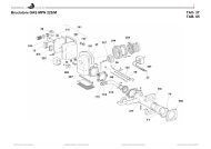
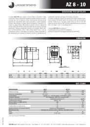
5. CARATTERISTICHE E DATI TECNICI<br />
5.2 Circuito idraulico<br />
Tabella. 10 - Legenda figure cap. 5<br />
278<br />
5 Camera stagna 38 Flussostato<br />
7 Entrata gas 39 Limitatore di portata acqua<br />
8 Uscita acqua sanitaria 42 Sensore di temperatura sanitaria<br />
9 Entrata acqua sanitaria 44 Valvola gas<br />
10 Mandata impianto 56 Vaso di espansione<br />
11 Ritorno impianto 72 Termostato ambiente (non fornito)<br />
14 Valvola di sicurezza 74 Rubinetto di riempimento impianto<br />
16 Ventilatore 81 Elettrodo d’accensione e rilevazione<br />
19 Camera combustione 95 Valvola deviatrice<br />
22 Bruciatore 114 Pressostato acqua<br />
27 Scambiatore in rame per riscaldamento e sanitario 138 Sonda esterna (non fornito)<br />
28 Collettore fumi 139 Unità ambiente (non fornito)<br />
29 Collettore uscita fumi 187 Diaframma fumi<br />
32 Circolatore riscaldamento 194 Scambiatore acqua sanitaria<br />
36 Sfiato aria automatico <strong>24</strong>1 Bypass automatico<br />
37 Filtro entrata acqua fredda 278 Sensore doppio (Sicurezza + Riscaldamento)<br />
5.1 Vista generale e componenti principali<br />
29<br />
187<br />
27<br />
95<br />
194<br />
<strong>24</strong>1 42<br />
38<br />
114 36<br />
32<br />
74<br />
56<br />
14<br />
5<br />
16<br />
28<br />
56<br />
27<br />
10 8 9 11<br />
278<br />
fig. 22 - Circuito riscaldamento<br />
278<br />
81<br />
22<br />
19<br />
27<br />
114 36<br />
56<br />
95<br />
194<br />
14<br />
14<br />
194<br />
36<br />
32<br />
95<br />
114<br />
<strong>24</strong>1 42<br />
38<br />
74<br />
10 42 8 44 7 39 9 38 74 11 32<br />
37<br />
fig. 21 - Vista generale <strong>CLIZIA</strong> D <strong>24</strong> <strong>AS</strong><br />
10 8 9<br />
fig. 23 - Circuito sanitario<br />
11<br />
cod. 3541C810 - Rev. 00 - 09/2012<br />
IT<br />
9
<strong>CLIZIA</strong> D <strong>24</strong> <strong>AS</strong><br />
5.3 Tabella dati tecnici 5.4 Diagrammi<br />
Dato Unità <strong>CLIZIA</strong> D <strong>24</strong> <strong>AS</strong><br />
Portata termica max kW 25.8 (Q)<br />
Portata termica min kW 8.3 (Q)<br />
Potenza Termica max riscaldamento kW <strong>24</strong>.0 (P)<br />
Potenza Termica min riscaldamento kW 7.2 (P)<br />
Potenza Termica max sanitario kW <strong>24</strong>.0<br />
Potenza Termica min sanitario kW 7.2<br />
Rendimento Pmax (80-60°C) % 93.0<br />
Rendimento 30% % 90.5<br />
Classe efficienza direttiva 92/42 EEC -<br />
Classe di emissione NOx - 3 (
<strong>CLIZIA</strong> D <strong>24</strong> <strong>AS</strong><br />
5.5 Schema elettrico<br />
1kW<br />
81<br />
LC32<br />
ABM01<br />
N<br />
L<br />
L<br />
N<br />
1 2 3 95<br />
°<br />
T<br />
°<br />
T ° T<br />
114<br />
38<br />
42<br />
278<br />
44<br />
32<br />
16<br />
N<br />
L<br />
230V<br />
50 Hz<br />
72<br />
138<br />
139<br />
1 2 3 4<br />
fig. <strong>24</strong> - Circuito elettrico<br />
A<br />
Attenzione: Prima di collegare il termostato ambiente o il cronocomando remoto,<br />
togliere il ponticello sulla morsettiera.<br />
cod. 3541C810 - Rev. 00 - 09/2012<br />
IT<br />
11
<strong>CLIZIA</strong> D <strong>24</strong> <strong>AS</strong><br />
I<br />
I<br />
EN<br />
1. GENERAL WARNINGS<br />
• Carefully read and follow the instructions contained in this instruction booklet.<br />
• After boiler installation, inform the user regarding its operation and give him this manual, which is<br />
an integral and essential part of the product and must be kept with care for future reference.<br />
• Installation and maintenance must be carried out by professionally qualified personnel, in compliance<br />
with the current regulations and according to the manufacturer's instructions. Do not carry<br />
out any operation on the sealed control parts.<br />
• Incorrect installation or inadequate maintenance can result in damage or injury. The Manufacturer<br />
declines any liability for damage due to errors in installation and use, or failure to follow the instructions.<br />
• Before carrying out any cleaning or maintenance operation, disconnect the unit from the electrical<br />
power supply using the switch and/or the special cut-off devices.<br />
• In case of a fault and/or poor operation, deactivate the unit and do not try to repair it or directly<br />
intervene. Contact professionally qualified personnel. Any repair/replacement of the products<br />
must only be carried out by qualified personnel using original replacement parts. Failure to comply<br />
with the above could affect the safety of the unit.<br />
• This unit must only be used for its intended purpose. Any other use is deemed improper and therefore<br />
hazardous.<br />
• The packing materials are potentially hazardous and must not be left within the reach of children.<br />
• The unit must not be used by people (including children) with limited physical, sensory or mental<br />
abilities or without experience and knowledge of it, unless instructed or supervised in its use by<br />
someone responsible for their safety.<br />
• The unit and its accessories must be appropriately disposed of, in compliance with the current regulations.<br />
• The images given in this manual are a simplified representation of the product. In this representation<br />
there may be slight and insignificant differences with respect to the product supplied.<br />
2. OPERATING INSTRUCTIONS<br />
2.1 Introduction<br />
<strong>CLIZIA</strong> D <strong>24</strong> <strong>AS</strong> is a high-efficiency heat generator for heating and domestic hot water<br />
production, running on natural gas, equipped with an open-flue burner with electronic ignition,<br />
sealed chamber with forced ventilation, and microprocessor control system, designed<br />
for installation indoors or outdoors in a partially protected place (in compliance<br />
with EN 297/A6) for temperatures to -5°C.<br />
2.2 Control panel<br />
Panel<br />
Domestic hot water (DHW)<br />
A DHW demand (generated by drawing domestic hot water) is indicated by flashing of<br />
the hot water under the tap on the display.<br />
The display (detail 11 - fig. 1) shows the actual DHW outlet temperature and, during<br />
DHW standby time, the message “d1“.<br />
Comfort<br />
A Comfort demand (reinstatement of temperature inside the boiler) is indicated by flashing<br />
of the water under the tap on the display. The display (detail 11 - fig. 1) shows the<br />
actual temperature of the water in the boiler.<br />
Fault<br />
In case of a fault (see cap. 4.4) the display shows the fault code (detail 11 - fig. 1) and,<br />
during safety standby times, the messages "d3" and "d4".<br />
2.3 Lighting and turning off<br />
Connection to the power supply<br />
• During the first 5 seconds the display will also show the card software release.<br />
• Open the gas cock ahead of the boiler.<br />
• The boiler is now ready to function automatically whenever domestic hot water is<br />
drawn or in case of a heating demand (generated by Room Thermostat or Remote<br />
Temperature Control).<br />
Turning the boiler off and on<br />
Press the on/off button (detail 7 - fig. 1) for 5 seconds.<br />
fig. 2 - Turning the boiler off<br />
When the boiler is turned off, the PCB is still powered. Domestic hot water and heating<br />
are disabled. The antifreeze system remains activated. To relight the boiler, press the<br />
on/off button (detail 7 - fig. 1) again for 5 seconds.<br />
1<br />
2<br />
9 10 15<br />
7<br />
17<br />
8<br />
5<br />
11<br />
12<br />
eco<br />
comfort<br />
reset<br />
14 3 4 13 16 6<br />
fig. 1 - Control panel<br />
Key of panel fig. 1<br />
1 DHW temperature setting decrease button<br />
2 DHW temperature setting increase button<br />
3 Heating system temperature setting decrease button<br />
4 Heating system temperature setting increase button<br />
5 Display<br />
6 "Sliding Temperature" Menu - Summer/Winter mode selection - Reset button<br />
7 Unit On/Off - Economy/Comfort mode selection button<br />
8 DHW symbol<br />
9 DHW mode<br />
10 Summer mode<br />
11 Multifunction<br />
12 Eco (Economy) mode<br />
13 Heating<br />
14 Heating symbol<br />
15 Burner lit and actual power level (flashing during combustion fault function)<br />
16 Service Tool connection<br />
17 Water gauge<br />
Indication during operation<br />
Heating<br />
A heating demand (generated by the Room Thermostat or Remote Timer Control) is indicated<br />
by flashing of the hot air above the radiator on the display.<br />
The display (detail 11 - fig. 1) shows the actual heating delivery temperature and, during<br />
heating standby time, the message “d2”.<br />
1<br />
0<br />
2<br />
3<br />
4<br />
fig. 3<br />
The boiler will be immediately ready to work whenever domestic hot water is drawn or in<br />
case of a heating demand (generated by the Room Thermostat or the Remote Timer<br />
control).<br />
B<br />
The antifreeze system does not work when the power and/or gas to the unit are<br />
turned off. To avoid damage caused by freezing during long idle periods in winter,<br />
it is advisable to drain all water from the boiler, DHW circuit and system; or<br />
drain just the DHW circuit and add a suitable antifreeze to the heating system,<br />
complying with that prescribed insec. 3.3.<br />
2.4 Adjustments<br />
Summer/Winter Switchover<br />
Press the summer/winter button (detail 6 - fig. 1) for 2 seconds.<br />
The display activates the Summer symbol (detail 10 - fig. 1): the boiler will only deliver<br />
domestic hot water. The antifreeze system remains activated.<br />
To deactivate the Summer mode, press the summer/winter button (detail 6 - fig. 1)<br />
again for 2 seconds.<br />
Heating temperature adjustment<br />
Use the heating buttons (details 3 and 4 - fig. 1) to vary the temperature from a min. of<br />
30°C to a max. of 80°C; in any case, it is advisable not to operate the boiler below 45°C.<br />
I<br />
I<br />
fig. 4<br />
Domestic hot water (DHW) temperature adjustment<br />
Use the DHW buttons (details 1 and 2 - fig. 1) to adjust the temperature from a min. of<br />
40°C to a max. of 55°C.<br />
I<br />
I<br />
I<br />
I<br />
I<br />
I<br />
I<br />
I<br />
I<br />
I<br />
I<br />
I<br />
I<br />
I<br />
fig. 5<br />
12 EN cod. 3541C810 - Rev. 00 - 09/2012
<strong>CLIZIA</strong> D <strong>24</strong> <strong>AS</strong><br />
Room temperature adjustment (with optional room thermostat)<br />
Using the room thermostat, set the temperature required in the rooms. If the room thermostat<br />
is not installed, the boiler will keep the system at the set system delivery setpoint<br />
temperature.<br />
Room temperature adjustment (with optional remote timer control)<br />
Using the remote timer control, set the required temperature in the rooms. The boiler will<br />
adjust the system water according to the required room temperature. For operation with<br />
remote timer control, please refer to the relevant instruction manual.<br />
ECO/COMFORT selection<br />
The unit has a function that ensures a high domestic hot water delivery speed and maximum<br />
comfort for the user. When the device is activated (COMFORT mode), the water<br />
contained in the boiler is kept hot, thereby ensuring immediate availability of hot water<br />
on opening the tap, without waiting times.<br />
The user can deactivate the device (ECO mode) by pressing the eco/comfort button<br />
(detail 7 - fig. 1). In ECO mode the display activates the ECO symbol (detail 12 - fig. 1).<br />
To activate the COMFORT mode, press the eco/comfort button (detail 7 - fig. 1) again.<br />
Sliding Temperature<br />
When the optional external probe is installed, the boiler adjustment system works with<br />
"Sliding Temperature”. In this mode, the temperature of the heating system is controlled<br />
according to the outside weather conditions, to ensure high comfort and energy saving<br />
throughout the year. In particular, the system delivery temperature is decreased as the<br />
outside temperature increases, according to a specific "compensation curve”.<br />
With Sliding Temperature adjustment, the temperature set with the heating buttons (detail<br />
3 - fig. 1) becomes the maximum system delivery temperature. It is advisable to set<br />
a maximum value to allow system adjustment throughout its useful operating range.<br />
The boiler must be adjusted at the time of installation by qualified personnel. Possible<br />
adjustments can in any case be made by the user to improve comfort.<br />
Compensation curve and curve offset<br />
Press the reset button (detail 6 - fig. 1) for 5 seconds to access the "Sliding temperature"<br />
menu; the display shows "CU" flashing.<br />
Use the DHW buttons (detail 1 - fig. 1) to adjust the curve from 1 to 10 according to the<br />
characteristic. By setting the curve to 0, sliding temperature adjustment is disabled.<br />
Press the heating buttons (detail 3 - fig. 1) to access parallel curve offset; the display<br />
shows "OF" flashing. Use the DHW buttons (detail 1 - fig. 1) to adjust the parallel curve<br />
offset according to the characteristic (fig. 6).<br />
Press the reset button (detail 6 - fig. 1) again for 5 seconds to exit the "Sliding Temperature"<br />
menu.<br />
If the room temperature is lower than the required value, it is advisable to set a higher<br />
order curve and vice versa. Proceed by increasing or decreasing in steps of one and<br />
check the result in the room.<br />
90<br />
85<br />
80<br />
70<br />
60<br />
50<br />
40<br />
30<br />
20<br />
OFFSET = 20 OFFSET = 40<br />
fig. 6 - Example of compensation parallel curve offset<br />
Adjustments from Remote Timer Control<br />
If the Remote Timer Control (optional) is connected to the boiler, the above adjustments<br />
are managed according to that given in table 1.<br />
A<br />
Table. 1<br />
20 10 0 -10 -20<br />
Heating temperature setting<br />
DHW temperature adjustment<br />
Summer/Winter Switchover<br />
Eco/Comfort selection<br />
Sliding Temperature<br />
10 9 8 7<br />
6<br />
5<br />
4<br />
3<br />
2<br />
1<br />
90<br />
85<br />
80<br />
70<br />
60<br />
50<br />
40<br />
30<br />
20<br />
10 9 8 7<br />
20 10 0 -10 -20<br />
Adjustment can be made from the Remote Timer Control menu<br />
and the boiler control panel.<br />
Adjustment can be made from the Remote Timer Control menu<br />
and the boiler control panel.<br />
Summer mode has priority over a possible Remote Timer Control<br />
heating demand.<br />
On disabling DHW from the Remote Timer Control menu, the<br />
boiler selects the Economy mode. In this condition, the eco/comfort<br />
button (detail 7 - fig. 1) on the boiler panel is disabled.<br />
On enabling DHW from the Remote Timer Control menu, the<br />
boiler selects the Comfort mode. In this condition it is possible<br />
select one of the two modes with the eco/comfort button (detail 7<br />
- fig. 1) on the boiler panel.<br />
Both the Remote Timer Control and the boiler card manage Sliding<br />
Temperature adjustment: the boiler card Sliding Temperature<br />
has priority.<br />
6<br />
5<br />
4<br />
3<br />
2<br />
1<br />
System water pressure adjustment<br />
The filling pressure with system cold, read on boiler water gauge (detail 17 - fig. 1), must<br />
be approx. 1.0 bar. If the system pressure falls to values below minimum, the boiler stops<br />
and fault F37 is displayed. Operate the filling cock detail 1 - fig. 7 and bring it to the initial<br />
value. Always close the filling cock at the end of the operation.<br />
fig. 7 - Filling cock<br />
3. INSTALLATION<br />
3.1 General Instructions<br />
BOILER INSTALLATION MUST ONLY BE PERFORMED BY QUALIFIED PERSON-<br />
NEL, IN ACCORDANCE WITH ALL THE INSTRUCTIONS GIVEN IN THIS TECHNICAL<br />
MANUAL, THE PROVISIONS OF CURRENT LAW, THE PRESCRIPTIONS OF NA-<br />
TIONAL AND LOCAL STANDARDS AND THE RULES OF PROPER WORKMANSHIP.<br />
3.2 Place of installation<br />
The combustion circuit is sealed with respect to the place of installation, therefore the<br />
unit can be installed in any room. However, the place of installation must be sufficiently<br />
ventilated to prevent the creation of dangerous conditions in case of even small gas<br />
leaks. This safety standard is required by the EEC Directive no. 2009/142 for all gas<br />
units, including those with sealed chamber<br />
The unit is suitable for operation in a partially protected place in compliance with EN 297<br />
pr A6, for temperatures to -5°C. It is advisable to install the boiler under the slope of a<br />
roof, inside a balcony or in a sheltered recess.<br />
Therefore the place of installation must be free of dust, flammable materials or objects<br />
or corrosive gases.<br />
The boiler is arranged for wall mounting and comes standard with a hooking bracket. Fix<br />
the bracket to the wall according to the measurements given in the cover drawing and<br />
hook the boiler on it. A metal template for marking the drilling points on the wall is available<br />
by request. The wall fixing must ensure stable and effective support for the generator.<br />
If the unit is enclosed in a cabinet or mounted alongside, a space must be provided<br />
for removing the casing and for normal maintenance operations<br />
A<br />
3.3 Plumbing connections<br />
Important<br />
B<br />
The safety valve outlet must be connected to a funnel or collection pipe to prevent<br />
water spurting onto the floor in case of overpressure in the heating circuit.<br />
Otherwise, if the discharge valve cuts in and floods the room, the boiler manufacturer<br />
cannot be held liable.<br />
B<br />
Before making the connection, check that the unit is arranged for operation with<br />
the type of fuel available and carefully clean all the system pipes.<br />
Carry out the relevant connections according to the cover diagram and the symbols given<br />
on the unit.<br />
Note: The unit has an internal bypass in the heating circuit.<br />
Water system characteristics<br />
In the presence of water harder than 25° Fr (1°F = 10ppm CaCO 3 ), use suitably treated<br />
water in order to avoid possible scaling in the boiler.<br />
Antifreeze system, antifreeze fluids, additives and inhibitors<br />
When necessary, antifreeze fluids, additives and inhibitors can be used only if the manufacturer<br />
of such fluids or additives guarantees that they are suitable and do not cause<br />
damage to the exchanger or other components and/or materials of the boiler and system.<br />
Do not use generic antifreeze fluids, additives or inhibitors that are not specific for use in<br />
heating systems and compatible with the materials of the boiler and system.<br />
3.4 Gas connection<br />
The gas must be connected to the relevant union (see figure on cover) in conformity with<br />
the current regulations, with a rigid metal pipe or with a continuous surface flexible s/steel<br />
tube, installing a gas cock between the system and boiler. Make sure all the gas connections<br />
are tight.<br />
1<br />
cod. 3541C810 - Rev. 00 - 09/2012<br />
EN<br />
13
<strong>CLIZIA</strong> D <strong>24</strong> <strong>AS</strong><br />
3.5 Electrical connections<br />
Important<br />
B<br />
The unit must be connected to an efficient earthing system in conformity with<br />
current safety regulations. Have the efficiency and suitability of the earthing<br />
system checked by professionally qualified personnel; the Manufacturer declines<br />
any liability for damage caused by failure to earth the system.<br />
The boiler is prewired and provided with a "Y" type cable (without plug) for connection<br />
to the electric line. The connections to the power supply must be permanent<br />
and equipped with a double-pole switch with contact opening distance<br />
of at least 3 mm, installing fuses of max. 3A between the boiler and the line.<br />
Make sure to respect the polarities (LINE: brown wire / NEUTRAL: blue wire /<br />
EARTH: yellow/green wire) in connections to the electric line.<br />
B<br />
The unit's power cable must not be replaced by the user; if damaged, switch<br />
the unit off and have the cable replaced by professionally qualified personnel.<br />
If replacing the power cable, only use "HAR H05 VV-F" 3x0.75 mm2 cable with<br />
max. ext. diameter of 8 mm.<br />
Room thermostat (optional)<br />
B<br />
IMPORTANT: THE ROOM THERMOSTAT MUST HAVE VOLTAGE-FREE<br />
CONTACTS. CONNECTING 230 V TO THE ROOM THERMOSTAT TERMI-<br />
NALS WILL PERMANENTLY DAMAGE THE ELECTRONIC BOARD.<br />
When connecting time controls or a timer, do not take the power supply for these<br />
devices from their breaking contacts Their power supply must be by means of direct<br />
connection from the mains or with batteries, depending on the kind of device.<br />
Accessing the electrical terminal block<br />
The electrical terminal block can be accessed after removing the casing. The layout of<br />
the terminals for the various connections is also given in the wiring diagram in fig. <strong>24</strong>.<br />
Connection with coaxial pipes<br />
fig. 9 - Examples of connection with coaxial pipes ( = Air / = Fumes)<br />
Table. 2 - Typology<br />
Type<br />
C1X<br />
C3X<br />
C1X<br />
For coaxial connection, fit the unit with one of the following starting accessories. For the<br />
wall hole dimensions, refer to the figure on the cover.<br />
Table. 3 - Starting accessories for coaxial ducts<br />
Code 010006X0 - 08522870<br />
Description<br />
Wall horizontal exhaust and inlet<br />
Roof vertical exhaust and inlet<br />
Ø100<br />
Ø60<br />
C3X C3X C3X<br />
Code 010008X0 - 08522880<br />
C1X C1X<br />
Ø126<br />
Ø82<br />
138<br />
45.6<br />
100<br />
Ø60<br />
Ø130<br />
1 2 3 4 5 6<br />
3 4<br />
Code 010007X0<br />
fig. 10<br />
Code 08522890<br />
fig. 11<br />
72<br />
139<br />
fig. 8 - Accessing the terminal block<br />
3.6 Fume ducts<br />
Important<br />
The unit is a "C type" with sealed chamber and forced draught, the air inlet and fume outlet<br />
must be connected to one of the following extraction/suction systems. The unit is approved<br />
for operation with all the Cny flue configurations given on the dataplate. Some<br />
configurations may be expressly limited or not permitted by law, standards or local regulations.<br />
Before installation, check and carefully follow the instructions. Also, comply with<br />
the instructions on the positioning of wall and/or roof terminals and the minimum distances<br />
from windows, walls, ventilation openings, etc.<br />
Baffles<br />
Boiler operation requires fitting the baffles supplied with the unit. Check that the boiler<br />
has right baffle (if to be used) and its correct positioning.<br />
A<br />
1<br />
B<br />
3<br />
3<br />
5<br />
fig. 12<br />
Ø60<br />
Ø100<br />
68<br />
Table. 4 - Baffles for coaxial ducts<br />
118<br />
Ø60<br />
Ø100<br />
20<br />
fig. 13<br />
Ø60<br />
Ø100<br />
26 89<br />
118<br />
Coaxial 60/100 Coaxial 80/125<br />
Max. permissible length 5 m 10 m<br />
Reduction factor 90° bend 1 m 0.5 m<br />
Reduction factor 45° bend 0.5 m 0.25 m<br />
Baffle to use<br />
0 ÷ 2 m Ø 43 0 ÷ 3 m Ø 43<br />
2 ÷ 5 m no baffle 3 ÷ 10 m no baffle<br />
2<br />
2<br />
4<br />
6<br />
1<br />
A Baffle replacement with boiler not installed<br />
B Baffle replacement with boiler and fume ducts already installed<br />
14 EN cod. 3541C810 - Rev. 00 - 09/2012
<strong>CLIZIA</strong> D <strong>24</strong> <strong>AS</strong><br />
Connection with separate pipes<br />
Table. 7 - Accessories<br />
C5x<br />
fig. 14 - Examples of connection with separate pipes ( = Air / = Fumes)<br />
Table. 5 - Typology<br />
C3x<br />
B2x<br />
C1x<br />
Type Description<br />
C1X Wall horizontal exhaust and intake. The inlet/outlet terminals must be concentric or close enough to be<br />
undergo similar wind conditions (within 50 cm)<br />
C3X Roof vertical exhaust and intake. Inlet/outlet terminals like for C12<br />
C5X Wall or roof exhaust and intake separate or in any case in areas with different pressures. The exhaust<br />
and intake must not be positioned on opposite walls.<br />
C6X Intake and exhaust with separately certified pipes (EN 1856/1)<br />
B2X Intake from installation room and wall or roof exhaust<br />
IMPORTANT - THE ROOM MUST BE PROVIDED WITH APPROPRIATE VENTILATION<br />
For the connection of separate ducts, fit the unit with the following starting accessory:<br />
50<br />
80<br />
80<br />
max 50 cm<br />
32<br />
Ø 80<br />
Ø 100<br />
Ø 60<br />
Air<br />
inlet<br />
Losses in m eq<br />
Fume exhaust<br />
Vertical Horizontal<br />
PIPE 0.5 m M/F 1KWMA38A 0.5 0.5 1.0<br />
1 m M/F 1KWMA83A 1.0 1.0 2.0<br />
2 m M/F 1KWMA06K 2.0 2.0 4.0<br />
BEND 45° F/F 1KWMA01K 1.9 2.9<br />
45° M/F 1KWMA65A 1.9 2.9<br />
90° F/F 1KWMA02K 2.0 3.0<br />
90° M/F 1KWMA82A 1.5 2.5<br />
90° M/F + Test point 1KWMA70U 1.5 2.5<br />
PIPE SECTION with test point 1KWMA16U 0.2 0.2<br />
for condensate drain 1KWMA55U - 3.0<br />
TEE for condensate drain 1KWMA05K - 7.0<br />
TERMINAL air, wall 1KWMA85A 2.0 -<br />
fumes, wall with antiwind 1KWMA86A - 5.0<br />
FLUE Split air/fumes 80/80 1KWMA84U - 12.0<br />
Fume outlet only Ø80 1KWMA83U +<br />
1KWMA86U<br />
- 4.0<br />
REDUCTION from Ø80 to Ø100 1KWMA03U 0.0 0.0<br />
from Ø100 to Ø80 1.5 3.0<br />
PIPE 1 m M/F 1KWMA08K 0.4 0.4 0.8<br />
BEND 45° M/F 1KWMA03K 0.6 1.0<br />
90° M/F 1KWMA04K 0.8 1.3<br />
TERMINAL air, wall 1KWMA14K 1.5 -<br />
fumes, wall with antiwind 1KWMA29K - 3.0<br />
PIPE 1 m M/F 010028X0 - 2.0 6.0<br />
BEND 90° M/F 010029X0 - 6.0<br />
REDUCTION 80 - 60 010030X0 - 8.0<br />
TERMINAL fumes, wall 1KWMA90A - 7.0<br />
ATTENTION: CONSIDER THE HIGH PRESSURE LOSSES OF Ø60 ACCESSORIES;<br />
USE THEM ONLY IF NECESSARY AND AT THE L<strong>AS</strong>T FUME EXHAUST SECTION.<br />
Connection to collective flues<br />
010011X0<br />
fig. 15 - Starting accessory for separate ducts<br />
Before installation, check the baffle to be used and that the maximum permissible length<br />
is not exceeded, by means of a simple calculation:<br />
1. Completely establish the layout of the system of split flues, including accessories<br />
and outlet terminals.<br />
2. Consult the table 7 and identify the losses in m eq (equivalent metres) of every component,<br />
according to the installation position.<br />
3. Check that the sum total of losses is less than or equal to the maximum permissible<br />
length in table 6.<br />
Table. 6 - Baffles for separate ducts<br />
Max. permissible length<br />
Baffle to use<br />
0.852290.0<br />
<strong>CLIZIA</strong> D <strong>24</strong> <strong>AS</strong><br />
60 m eq<br />
0 - 20 m eq Ø 43<br />
20 - 45 m eq<br />
Ø 47<br />
45 - 60 m eq<br />
No baffle<br />
fig. 16 - Examples of connection to flues ( = Air / = Fumes)<br />
Table. 8 - Typology<br />
Type<br />
C2X<br />
C4X<br />
C8X<br />
B3X<br />
C8X<br />
C2X<br />
C4X<br />
Description<br />
Intake and exhaust in common flue (intake and exhaust in same flue)<br />
Intake and exhaust in common and separate flues , but undergoing similar wind conditions<br />
Exhaust in single or common flue and wall intake<br />
Intake from installation room by means of concentric duct (that encloses the exhaust) and exhaust in<br />
common flue with natural draught<br />
IMPORTANT - THE ROOM MUST BE PROVIDED WITH APPROPRIATE VENTILATION<br />
If the boiler is to be connected <strong>CLIZIA</strong> D <strong>24</strong> <strong>AS</strong> to a collective flue or a single flue with<br />
natural draught, the flue or chimney must be expressly designed by professionally qualified<br />
technical personnel in conformity with the current regulations and be suitable for<br />
sealed chamber units equipped with fan.<br />
cod. 3541C810 - Rev. 00 - 09/2012<br />
EN<br />
15
I<br />
I<br />
I<br />
I<br />
I<br />
I<br />
I<br />
I<br />
I<br />
I<br />
I<br />
I<br />
I<br />
I<br />
I<br />
I<br />
I<br />
I<br />
I<br />
I<br />
I<br />
I<br />
<strong>CLIZIA</strong> D <strong>24</strong> <strong>AS</strong><br />
4. SERVICE AND MAINTENANCE<br />
4.1 Adjustments<br />
Gas conversion<br />
The unit can operate on natural gas or LPG and is factory-set for use with one of these<br />
two gases, as clearly shown on the packing and on the dataplate. Whenever a gas different<br />
from that for which the unit is arranged has to be used, the special conversion kit<br />
will be required, proceeding as follows:<br />
1. Replace the nozzles at the main burner, fitting the nozzles specified in the technical<br />
data table in cap. 5, according to the type of gas used<br />
2. Modify the parameter for the type of gas:<br />
• put the boiler in standby mode<br />
• press the DHW buttons (details 1 and 2 - fig. 1) for 10 seconds: the display<br />
shows “b01“ blinking.<br />
• Press the DHW buttons (details 1 and 2 - fig. 1) to set parameter 00 (for natural<br />
gas operation) or 01 (for LPG operation).<br />
• press the DHW buttons (details 1 and 2 - fig. 1) for 10 seconds.<br />
• the boiler will return to standby mode<br />
3. Adjust the minimum and maximum pressures at the burner (ref. relevant paragraph),<br />
setting the values given in the technical data table for the type of gas used<br />
4. Apply the sticker contained in the conversion kit, near the dataplate as proof of the<br />
conversion.<br />
TEST mode activation<br />
Press the heating buttons (details 3 and 4 - fig. 1) together for 5 seconds to activate the<br />
TEST mode. The boiler lights at the maximum heating power set as described in the following<br />
section.<br />
The heating and DHW symbols (fig. 17) flash on the display; the heating power will appear<br />
alongside.<br />
R<br />
S<br />
fig. 18 - Gas valve<br />
B<br />
I<br />
A<br />
A - Upstream pressure point<br />
B - Downstream pressure point<br />
I - Gas valve electrical connection<br />
R - Gas outlet<br />
S - Gas inlet<br />
~ <strong>24</strong>Ω<br />
TYPE SGV100<br />
Pi max 65 mbar<br />
<strong>24</strong> Vdc - class B+A<br />
fig. 19 - Gas valve connection<br />
~ 65Ω<br />
I<br />
I<br />
I<br />
I<br />
I<br />
I<br />
I<br />
I<br />
I<br />
I<br />
I<br />
I<br />
I<br />
I<br />
I<br />
I<br />
I<br />
I<br />
I<br />
I<br />
I<br />
I<br />
fig. 17 - TEST mode (heating power = 100%)<br />
Press the heating buttons (details 3 and 4 - fig. 1) to increase or decrease the power<br />
(Min.=0%, Max.=100%).<br />
By pressing the DHW “-” button (detail 1 - fig. 1), boiler output is immediately adjusted<br />
to min. (0%). By pressing the DHW “+” button (detail 2 - fig. 1), boiler output is immediately<br />
adjusted to max. (100%).<br />
If the TEST mode is activated and enough hot water is drawn to activate the DHW mode,<br />
the boiler remains in TEST mode but the 3-way valve goes to DHW.<br />
To deactivate the TEST mode, press the heating buttons (details 3 and 4 - fig. 1) together<br />
for 5 seconds.<br />
The TEST mode is automatically deactivated in any case after 15 minutes or on stopping<br />
of hot water drawing (if enough hot water has been drawn to activate the DHW mode).<br />
Pressure adjustment at the burner<br />
Since this unit has flame modulation, there are two fixed pressure settings: minimum and<br />
maximum, which must be those given in the technical data table according to the type of<br />
gas.<br />
• Connect a suitable pressure gauge to the pressure point "B" downstream of the<br />
gas valve.<br />
• Activate the TEST mode (see cap. 4.1).<br />
• Press the Eco/Comfort button for 2 seconds to access the gas valve Calibration<br />
mode.<br />
• The card goes to the setting “q02”; displaying the actually saved value, by pressing<br />
the DHW buttons .<br />
• If the pressure gauge reading is different from the nominal maximum pressure, proceed<br />
by increases/decreases of 1 or 2 units of parameter “q02” by pressing the<br />
DHW buttons : the value is stored after each modification; wait 10 seconds for the<br />
pressure to stabilise.<br />
• Press the heating button “-” (ref. 3 - fig. 1).<br />
• The card goes to the setting “q01”; displaying the actually saved value, by pressing<br />
the DHW buttons .<br />
• If the pressure gauge reading is different from the nominal minimum pressure, proceed<br />
by increases/decreases of 1 or 2 units of parameter “q01” by pressing the<br />
DHW buttons : the value is stored after each modification; wait 10 seconds for the<br />
pressure to stabilise.<br />
• Recheck both adjustments by pressing the heating buttons and adjust them if necessary<br />
by repeating the above procedure.<br />
• Press the Eco/Comfort button for 2 seconds to return to the TEST mode.<br />
• Deactivate the TEST mode (see cap. 4.1).<br />
• Disconnect the pressure gauge.<br />
eco<br />
comfort<br />
reset<br />
1<br />
0<br />
2<br />
3<br />
4<br />
Heating power adjustment<br />
To adjust the heating power, switch the boiler to TEST mode (see sec. 4.1). Press the<br />
heating buttons (detail 3 - fig. 1) to increase or decrease the power (min. = 00 - max. =<br />
100). Press the reset button within 5 seconds and the max. power will remain that just<br />
set. Exit TEST mode (see sec. 4.1).<br />
Configuration Menu<br />
Press the DHW buttons together for 10 seconds to access the configuration Menu. 7 parameters<br />
are available, indicated by the letter "b", which are not modifiable from Remote<br />
Timer Control.<br />
Press the Heating buttons to scroll the list of parameters in increasing or decreasing order.<br />
Press the DHW buttons to view or modify the value of a parameter: the modification<br />
will be automatically saved.<br />
Contents Description Range Default <strong>CLIZIA</strong> D <strong>24</strong> <strong>AS</strong><br />
b01 Gas type selection<br />
0=Natural Gas<br />
1=LPG<br />
0=Natural Gas<br />
0=Natural Gas<br />
1=Bithermal instantaneous<br />
2=Monothermal instantaneous<br />
b02 Boiler type selection<br />
1=Bithermal instantane-<br />
2=Monothermal instanta-<br />
valve)<br />
4=Heating only (circulating<br />
pump)<br />
3=Heating only (3-way ous<br />
neous<br />
0=Sealed Chamber combustion<br />
control<br />
(without fume pressure<br />
switch)<br />
1=Open Chamber (with<br />
fume thermostat)<br />
2=Sealed Chamber (with<br />
fume pressure switch)<br />
b03<br />
b04<br />
Combustion chamber<br />
type selection<br />
Primary Exchanger type<br />
selection<br />
(b03=0)<br />
3=Sealed Chamber combustion<br />
control 0=Sealed Chamber with<br />
(with fume thermostat on combustion control<br />
recuperator)<br />
4=LOW NOx Sealed<br />
Chamber combustion<br />
control<br />
(without fume pressure<br />
switch)<br />
5=LOW NOx Open<br />
Chamber<br />
(with fume thermostat)<br />
0=Flat<br />
1=Omega<br />
0=Flat<br />
2=--<br />
No effect on adjustment<br />
(b03=1)<br />
-- 0<br />
No effect on adjustment<br />
(b03=2)<br />
-- 0<br />
Primary Exchanger type 0=Flat<br />
selection<br />
(b03=3)<br />
1=Omega<br />
2=--<br />
0=Flat<br />
No effect on adjustment<br />
--<br />
(b03=4)<br />
0<br />
No effect on adjustment<br />
(b03=5)<br />
-- 0<br />
0=Sealed Chamber with<br />
combustion control<br />
(without fume pressure<br />
switch)<br />
0=Flat<br />
16 EN cod. 3541C810 - Rev. 00 - 09/2012
<strong>CLIZIA</strong> D <strong>24</strong> <strong>AS</strong><br />
Contents Description Range Default <strong>CLIZIA</strong> D <strong>24</strong> <strong>AS</strong><br />
0=External gas valve<br />
Relay card LC32<br />
1=System filling solenoid<br />
valve<br />
operation selection<br />
(b02=1)<br />
2=Solar 3-way<br />
0=External gas valve 0=External gas valve<br />
b05<br />
No effect on adjustment<br />
(b02=2)<br />
-- 0<br />
No effect on adjustment<br />
(b02=3)<br />
-- 0<br />
No effect on adjustment<br />
(b02=4)<br />
-- 0<br />
b06 Mains Voltage Frequency 0=50Hz 1=60Hz<br />
0=50Hz 0=50Hz<br />
Comfort burner on time<br />
(b02=1)<br />
0-20 seconds 5 seconds 5 seconds<br />
b07<br />
No effect on adjustment<br />
(b02=2)<br />
-- 5<br />
No effect on adjustment<br />
(b02=3)<br />
-- 5<br />
No effect on adjustment<br />
(b02=4)<br />
-- 5<br />
Notes:<br />
1. Parameters with more than one description vary their function and/or range in relation<br />
to the setting of the parameter given in brackets.<br />
2. Parameters with more than one description are reset to the default value if the parameter<br />
given in brackets is modified.<br />
To exit the configuration Menu press the DHW buttons together for 10 seconds, or exiting<br />
occurs automatically after 2 minutes.<br />
Service menu<br />
The card Service Menu is accessed by pressing the Reset button for 20 seconds. 4 submenus<br />
are available: press the Heating buttons to select, in increasing or decreasing order,<br />
"tS", "In", "Hi" or "rE". "tS" means Transparent Parameters Menu, "In" means<br />
Information Menu, "Hi" means History Menu: after selecting the submenu, press the Reset<br />
button again to access it; "rE" means History Menu Reset: see description.<br />
"tS" - Transparent Parameters Menu<br />
16 parameters indicated by the letter "P" are available: which are also modifiable from<br />
Remote Timer Control.<br />
Press the Heating buttons to scroll the list of parameters in increasing or decreasing order.<br />
Press the DHW buttons to view or modify the value of a parameter: the modification<br />
will be automatically saved.<br />
Contents Description Range Default <strong>CLIZIA</strong> D <strong>24</strong> <strong>AS</strong><br />
P01 Ignition ramp Offset 0-40 10 10<br />
P02 Heating ramp 1-20°C/minute 5°C/minute 5°C/minute<br />
P03 Heating standby time 0-10 minutes 2 minutes 2 minutes<br />
P04 Heating Post-Circulation 0-20 minutes 6 minutes 6 minutes<br />
P05<br />
Heating user max. setpoint<br />
31-85°C 80°C 80°C<br />
P06 Max. power in heating 0-100% 100% 100%<br />
0=Fixed<br />
1=Linked to set point<br />
Burner shutdown in hot<br />
2=Solar (5)<br />
water production (b02=1)<br />
3=Solar (10)<br />
4=Solar (20)<br />
0=Fixed<br />
P07<br />
1=Linked to set point<br />
Burner shutdown in hot<br />
2=Solar (5)<br />
water production (b02=2)<br />
3=Solar (10)<br />
4=Solar (20)<br />
Hot water tank hysteresis<br />
0-4°C<br />
(b02=3)<br />
0=Fixed<br />
0=Fixed<br />
2°C<br />
0=Fixed<br />
Hot water tank hysteresis<br />
0-4°C<br />
(b02=4)<br />
2°C<br />
DHW standby time<br />
(b02=1)<br />
0-60 seconds 30 seconds 60 seconds<br />
P08<br />
DHW standby time<br />
(b02=2)<br />
0-60 seconds 60 seconds<br />
DHW standby time<br />
(b02=3)<br />
0-60 seconds 30 seconds<br />
DHW standby time<br />
(b02=4)<br />
0-60 seconds 30 seconds<br />
DHW user max. set point<br />
50-65°C<br />
(b02=1)<br />
50°C 55°C<br />
P09<br />
DHW user max. set point<br />
50-65°C<br />
(b02=2)<br />
55°C<br />
DHW user max. set point<br />
50-65°C<br />
(b02=3)<br />
65°C<br />
DHW user max. set point<br />
50-65°C<br />
(b02=4)<br />
65°C<br />
Contents Description Range Default <strong>CLIZIA</strong> D <strong>24</strong> <strong>AS</strong><br />
Anti-inertia function temperature<br />
(b02=1)<br />
70-85°C 70°C 0<br />
No effect on adjustment<br />
--<br />
(b02=2)<br />
0<br />
P10<br />
Delivery temperature in<br />
hot water production 70-85°C 80°C<br />
(b02=3)<br />
Delivery temperature in<br />
hot water production 70-85°C 80°C<br />
(b02=4)<br />
Anti-inertia function Post-<br />
0-5 Seconds<br />
Circulation (b02=1)<br />
0 seconds 30 seconds<br />
P11<br />
DHW Post-Circulation<br />
(b02=2)<br />
0-60 Seconds<br />
DHW Post-Circulation<br />
(b02=3)<br />
0-60 Seconds<br />
DHW Post-Circulation<br />
(b02=4)<br />
0-60 Seconds<br />
P12 Max. power in DHW 0-100% 100% 100%<br />
P13 Absolute min. power 0-100% 0% 0%<br />
P14 Post-Ventilation<br />
0=Default<br />
1=50 seconds<br />
0=Default<br />
0=Default<br />
CO2 limit Offset (b03=0)<br />
0 (Minimum)<br />
30 (Maximum)<br />
20 20<br />
No effect on adjustment<br />
--<br />
(b03=1)<br />
P15<br />
No effect on adjustment<br />
--<br />
(b03=2)<br />
0 (Minimum)<br />
CO2 limit Offset (b03=3)<br />
30 (Maximum)<br />
CO2 limit Offset (b03=4)<br />
0 (Minimum)<br />
30 (Maximum)<br />
20<br />
No effect on adjustment<br />
--<br />
(b03=5)<br />
20<br />
P16<br />
Exchanger protection<br />
activation<br />
0=No F43<br />
1-15=1-15°C/second<br />
10°C/second<br />
10°C/second<br />
Notes:<br />
1. Parameters with more than one description vary their function and/or range in relation<br />
to the setting of the parameter given in brackets.<br />
2. Parameters with more than one description are reset to the default value if the parameter<br />
given in brackets is modified.<br />
3. The Maximum Heating Power parameter can also be modified in Test Mode.<br />
Press the Reset button to return to the Service Menu. Press the Reset button for 20 seconds<br />
to exit the card Service Menu, or exiting occurs automatically after 15 minutes.<br />
"In” - Information Menu<br />
7 pieces of information are available.<br />
Press the Heating buttons to scroll the list of information in increasing or decreasing order.<br />
Press the DHW buttons to display the value.<br />
Contents<br />
Description<br />
Range<br />
t01 NTC Heating sensor (°C) between 05 and 125 °C<br />
t02 NTC Safety sensor (°C) between 05 and 125 °C<br />
t03 NTC DHW sensor (°C) between 05 and 125 °C<br />
t04 NTC External sensor (°C) between -30 and 70°C (negative values flash)<br />
L05 Actual burner power (%) 00%=Min., 100%=Max.<br />
F06 Actual Flame resistance (Ohm) 00-99 Ohm (-- = burner off)<br />
St07 Fan step (Number) 0=Off, 1=Min, 2=Med, 3=Max<br />
Notes:<br />
1. In case of damaged sensor, the card displays hyphens.<br />
Press the Reset button to return to the Service Menu. Press the Reset button for 20 seconds<br />
to exit the card Service Menu or exiting occurs automatically after 15 minutes.<br />
"Hi" - History Menu<br />
The card can store the last 11 faults: the History datum item H1: represents the most recent<br />
fault that occurred; the History datum item H10: represents the least recent fault that<br />
occurred.<br />
The codes of the faults saved are also displayed in the corresponding menu of the Remote<br />
Timer Control.<br />
Press the Heating buttons to scroll the list of faults in increasing or decreasing order.<br />
Press the DHW buttons to display the value.<br />
Press the Reset button to return to the Service Menu. Press the Reset button for 20 seconds<br />
to exit the card Service Menu, or exiting occurs automatically after 15 minutes.<br />
"rE" - History Reset<br />
Press the Eco/Comfort button for 3 seconds to delete all the faults stored in the History<br />
Menu: the card will automatically exit the Service Menu, in order to confirm the operation.<br />
Press the Reset button for 20 seconds to exit the card Service Menu, or exiting occurs<br />
automatically after 15 minutes.<br />
cod. 3541C810 - Rev. 00 - 09/2012<br />
EN<br />
17
<strong>CLIZIA</strong> D <strong>24</strong> <strong>AS</strong><br />
4.2 Startup<br />
Before lighting the boiler<br />
• Check the seal of the gas system.<br />
• Check correct prefilling of the expansion tank.<br />
• Fill the water system and make sure all air contained in the boiler and the system<br />
has been vented.<br />
• Make sure there are no water leaks in the system, DHW circuits, connections or boiler.<br />
• Check correct connection of the electrical system and efficiency of the earthing system.<br />
• Make sure the gas pressure for heating is that required.<br />
• Make sure there are no flammable liquids or materials in the immediate vicinity of<br />
the boiler<br />
Checks during operation<br />
• Switch the unit on.<br />
• Check the tightness of the fuel circuit and water systems.<br />
• Check the efficiency of the flue and air/fume ducts while the boiler is working.<br />
• Make sure the water is circulating properly between the boiler and the systems.<br />
• Make sure the gas valve modulates correctly in the heating and domestic hot water<br />
production stages.<br />
• Check correct boiler lighting by performing various tests, turning it on and off with<br />
the room thermostat or remote control.<br />
• Make sure the fuel consumption indicated on the meter matches that given in the<br />
technical data table in cap. 5.<br />
• Make sure that with no demand for heating, the burner lights correctly on opening a<br />
hot water tap. Check that in heating mode, on opening a hot water tap, the heating<br />
circulating pump stops and there is regular production of hot water.<br />
• Make sure the parameters are programmed correctly and carry out any required<br />
customisation (compensation curve, power, temperatures, etc.).<br />
4.3 Maintenance<br />
Periodical check<br />
To ensure correct operation of the unit over time, have qualified personnel carry out a<br />
yearly check, providing for the following:<br />
• The control and safety devices (gas valve, flow meter, thermostats, etc.) must function<br />
correctly.<br />
• The fume exhaust circuit must be perfectly efficient.<br />
(Sealed chamber boiler: fan, pressure switch, etc. -The sealed chamber must be<br />
tight: seals, cable glands, etc.)<br />
(Open chamber boiler: anti-backflow device, fume thermostat, etc.)<br />
• The air-fume end piece and ducts must be free of obstructions and leaks<br />
• The burner and exchanger must be clean and free of deposits. For possible cleaning<br />
do not use chemical products or wire brushes.<br />
• The electrode must be properly positioned and free of scale.<br />
= =<br />
3 ± 0,5<br />
fig. 20 - Electrode positioning<br />
• The gas and water systems must be airtight.<br />
• The water pressure in the cold water system must be about 1 bar; otherwise, bring<br />
it to that value.<br />
• The circulating pump must not be blocked.<br />
• The expansion tank must be filled.<br />
• The gas flow and pressure must correspond to that given in the respective tables.<br />
4.4 Troubleshooting<br />
Diagnostics<br />
The boiler is equipped with an advanced self-diagnosis system. In case of a boiler fault,<br />
the display will flash together with the fault symbol (detail 11 - fig. 1) indicating the fault<br />
code.<br />
There are faults that cause permanent shutdown (marked with the letter "A"): to restore<br />
operation, press the RESET button (detail 6 - fig. 1) for 1 second or RESET on the optional<br />
remote timer control if installed; if the boiler fails to start, it is necessary to eliminate<br />
the fault.<br />
Faults marked with the letter "F" cause temporary shutdowns that are automatically reset<br />
as soon as the value returns within the boiler's normal working range.<br />
List of faults<br />
Table. 9<br />
Code<br />
fault<br />
Fault Possible cause Cure<br />
A01<br />
A02<br />
A03<br />
No burner ignition<br />
Flame present signal with<br />
burner off<br />
Overtemperature protection<br />
activation<br />
No gas<br />
Ignition/detection electrode fault<br />
Faulty gas valve<br />
Gas valve wiring disconnected<br />
Ignition power too low<br />
Electrode fault<br />
Card fault<br />
F04 Card parameter fault Wrong card parameter setting<br />
F05<br />
A06<br />
Card parameter fault<br />
Fan fault<br />
No flame after the ignition<br />
phase<br />
Check the regular gas flow to the<br />
boiler and that the air has been eliminated<br />
from the pipes<br />
Check the wiring of the electrode and<br />
that it is correctly positioned and free<br />
of any deposits<br />
Check the gas valve and replace it if<br />
necessary<br />
Check the wiring<br />
Adjust the ignition power<br />
Check the ionisation electrode wiring<br />
Check the card<br />
Heating sensor damaged<br />
Check the correct positioning and<br />
operation of the heating sensor<br />
No water circulation in the system Check the circulating pump<br />
Air in the system<br />
Vent the system<br />
Wrong card parameter setting<br />
Wiring disconnected<br />
Defective fan<br />
Card fault<br />
Check the card parameter and modify<br />
it if necessary<br />
Check the card parameter and modify<br />
it if necessary<br />
Check the wiring<br />
Check the fan<br />
Check the card<br />
Low pressure in the gas system Check the gas pressure<br />
Burner minimum pressure setting Check the pressures<br />
F07 Card parameter fault Wrong card parameter setting<br />
A09<br />
F10<br />
F11<br />
F14<br />
A16<br />
F20<br />
A21<br />
Gas valve fault<br />
Delivery sensor 1 fault<br />
DHW sensor fault<br />
Delivery sensor 2 fault<br />
Gas valve fault<br />
Combustion control fault<br />
Poor combustion fault<br />
Wiring disconnected<br />
Faulty gas valve<br />
Sensor damaged<br />
Wiring shorted<br />
Wiring disconnected<br />
Sensor damaged<br />
Wiring shorted<br />
Wiring disconnected<br />
Sensor damaged<br />
Wiring shorted<br />
Wiring disconnected<br />
Wiring disconnected<br />
Faulty gas valve<br />
Fan fault<br />
Faulty baffle<br />
Flue not correctly sized or<br />
obstructed<br />
Fault F20 generated 6 times in the<br />
last 10 minutes<br />
A23 Card parameter fault Wrong card parameter setting<br />
Check the card parameter and modify<br />
it if necessary<br />
Check the wiring<br />
Check the gas valve and replace it if<br />
necessary<br />
Check the wiring or replace the sensor<br />
Check the wiring or replace the sensor<br />
Check the wiring or replace the sensor<br />
Check the wiring<br />
Check the gas valve and replace it if<br />
necessary<br />
Check the fan and fan wiring<br />
Check the baffle and replace it if necessary<br />
Check the flue<br />
See fault F20<br />
Check the card parameter and modify<br />
it if necessary<br />
A<strong>24</strong> Card parameter fault Wrong card parameter setting<br />
Check the card parameter and modify<br />
it if necessary<br />
F34 Supply voltage under 180V. Electric mains trouble Check the electrical system<br />
F35 Faulty mains frequency Electric mains trouble Check the electrical system<br />
F37<br />
F39<br />
A41<br />
Incorrect system water pressure<br />
External probe fault<br />
Sensor positioning<br />
Pressure too low<br />
Water pressure switch damaged<br />
or not connected<br />
Fill the system<br />
Check the sensor<br />
Probe damaged or wiring shorted Check the wiring or replace the sensor<br />
Probe disconnected after activating<br />
Reconnect the external sensor or dis-<br />
the sliding temperature able the sliding<br />
temperature<br />
Delivery sensor or DHW sensor<br />
detached from the pipe<br />
Check the correct positioning and<br />
operation of the sensors<br />
F42 Heating sensor fault Sensor damaged Replace the sensor<br />
F43<br />
F50<br />
Exchanger protection trips.<br />
Gas valve fault<br />
No H 2 O system circulation<br />
Air in the system<br />
Modulating Operator wiring disconnected<br />
Faulty gas valve<br />
Check the circulating pump<br />
Vent the system<br />
Check the wiring<br />
A51 Poor combustion fault Inlet/exhaust flue obstruction Check the flue<br />
Check the gas valve and replace it if<br />
necessary<br />
18 EN cod. 3541C810 - Rev. 00 - 09/2012
<strong>CLIZIA</strong> D <strong>24</strong> <strong>AS</strong><br />
5. TECHNICAL DATA AND CHARACTERISTICS<br />
5.1 General view and main components<br />
29<br />
187<br />
5.2 Water circuit<br />
278<br />
5<br />
28<br />
27<br />
16<br />
56<br />
114 36<br />
56<br />
27<br />
95<br />
194<br />
14<br />
278<br />
32<br />
81<br />
22<br />
19<br />
<strong>24</strong>1 42<br />
38<br />
74<br />
194<br />
14<br />
36<br />
10 8 9<br />
fig. 22 - Heating Circuit<br />
11<br />
95<br />
114<br />
278<br />
10 42 8 44 7 39 9 38 74 11 32<br />
37<br />
fig. 21 - General view <strong>CLIZIA</strong> D <strong>24</strong> <strong>AS</strong><br />
Table. 10 - Key of figures cap. 5<br />
5 Sealed chamber 38 Flowswitch<br />
7 Gas inlet 39 Water flow limiter<br />
8 Domestic hot water outlet 42 DHW temperature sensor<br />
9 Cold water inlet 44 Gas valve<br />
10 System delivery 56 Expansion tank<br />
11 System return 72 Room thermostat (not supplied)<br />
14 Safety valve 74 System filling cock<br />
16 Fan 81 Ignition and detection electrode<br />
19 Combustion chamber 95 Diverter valve<br />
22 Burner 114 Water pressure switch<br />
27 Copper exchanger for heating and hot water 138 External probe (not supplied)<br />
28 Fume manifold 139 Room unit (not supplied)<br />
29 Fume outlet manifold 187 Fume baffle<br />
32 Heating circulating pump 194 DHW exchanger<br />
36 Automatic air vent <strong>24</strong>1 Automatic bypass<br />
37 Cold water inlet filter 278 Double sensor (Safety + Heating)<br />
27<br />
114 36<br />
95<br />
194<br />
32<br />
<strong>24</strong>1 42<br />
74<br />
38<br />
10 8 9 11<br />
fig. 23 - DHW Circuit<br />
56<br />
14<br />
cod. 3541C810 - Rev. 00 - 09/2012<br />
EN<br />
19
<strong>CLIZIA</strong> D <strong>24</strong> <strong>AS</strong><br />
5.3 Technical data table 5.4 Diagrams<br />
Data Unit <strong>CLIZIA</strong> D <strong>24</strong> <strong>AS</strong><br />
Max. heating capacity kW 25.8 (Q)<br />
Min. heating capacity kW 8.3 (Q)<br />
Max. Heat Output in heating kW <strong>24</strong>.0 (P)<br />
Min. Heat Output in heating kW 7.2 (P)<br />
Max. Heat Output in hot water production kW <strong>24</strong>.0<br />
Min. Heat Output in hot water production kW 7.2<br />
Efficiency Pmax (80-60°C) % 93.0<br />
Efficiency 30% % 90.5<br />
Efficiency class Directive 92/42 EEC -<br />
NOx emission class - 3 (
<strong>CLIZIA</strong> D <strong>24</strong> <strong>AS</strong><br />
5.5 Wiring diagram<br />
1kW<br />
81<br />
LC32<br />
ABM01<br />
N<br />
L<br />
L<br />
N<br />
1 2 3 95<br />
°<br />
T<br />
°<br />
T ° T<br />
114<br />
38<br />
42<br />
278<br />
44<br />
32<br />
16<br />
N<br />
L<br />
230V<br />
50 Hz<br />
72<br />
138<br />
139<br />
1 2 3 4<br />
fig. <strong>24</strong> - Electrical circuit<br />
A<br />
Important: Before connecting the room thermostat or the remote timer control,<br />
remove the jumper on the terminal block.<br />
cod. 3541C810 - Rev. 00 - 09/2012<br />
EN<br />
21
<strong>CLIZIA</strong> D <strong>24</strong> <strong>AS</strong><br />
I<br />
I<br />
ES<br />
1. ADVERTENCI<strong>AS</strong> GENERALES<br />
• Leer atentamente las advertencias de este manual de instrucciones.<br />
• Una vez instalado el equipo, describir su funcionamiento al usuario y entregarle este manual de<br />
instrucciones, el cual es parte integrante y esencial del producto y debe guardarse en un lugar<br />
seguro y accesible para futuras consultas.<br />
• La instalación y el mantenimiento deben ser realizados por un técnico autorizado, en conformidad<br />
con las normas vigentes y las instrucciones del fabricante. Se prohíbe manipular los dispositivos<br />
de regulación precintados.<br />
• La instalación incorrecta del equipo o la falta del mantenimiento apropiado puede causar daños<br />
materiales o personales. El fabricante no se hace responsable de los daños causados por errores<br />
de instalación o de uso y, en cualquier caso, por el incumplimiento de las instrucciones dadas.<br />
• Antes de efectuar cualquier operación de limpieza o mantenimiento, desconectar el equipo de la<br />
red eléctrica mediante el interruptor de la instalación u otro dispositivo de corte.<br />
• En caso de avería o funcionamiento incorrecto del equipo, desconectarlo y hacerlo reparar únicamente<br />
por un técnico autorizado. Acudir exclusivamente a personal autorizado. Las reparaciones<br />
del equipo y la sustitución de los componentes han de ser efectuadas solamente por técnicos<br />
autorizados y utilizando recambios originales. En caso contrario, se puede comprometer la seguridad<br />
del equipo.<br />
• Este equipo se ha de destinar solo al uso para el cual ha sido expresamente diseñado. Todo otro uso<br />
ha de considerarse impropio y, por lo tanto, peligroso.<br />
• Los materiales de embalaje son una fuente potencial de peligro: no dejarlos al alcance de los niños.<br />
• El equipo no debe ser utilizado por niños ni por adultos que tengan limitadas sus capacidades<br />
físicas, sensoriales o mentales, o que no cuenten con la experiencia y los conocimientos debidos,<br />
salvo que estén instruidos o supervisados por otra persona que se haga responsable de su seguridad.<br />
• Desechar el equipo y sus accesorios con arreglo a las normas vigentes.<br />
• Las imágenes contenidas en este manual son una representación simplificada del equipo. Dicha<br />
representación puede tener diferencias ligeras y no significativas con respecto al producto suministrado.<br />
2. INSTRUCCIONES DE USO<br />
2.1 Presentación<br />
<strong>CLIZIA</strong> D <strong>24</strong> <strong>AS</strong> es un generador térmico de alto rendimiento para calefacción y producción<br />
de agua caliente sanitaria, alimentado con gas natural y dotado de quemador atmosférico<br />
con encendido electrónico, cámara estanca de ventilación forzada y sistema<br />
de control con microprocesador, para instalar en el interior o en un sitio exterior parcialmente<br />
protegido (según la norma EN 297/A6) con temperaturas no inferiores a -5 °C.<br />
2.2 Panel de mandos<br />
Panel<br />
Agua caliente sanitaria<br />
La solicitud de agua sanitaria (generada por la toma de agua caliente sanitaria ) se indica mediante<br />
el parpadeo del símbolo del agua caliente debajo del símbolo del grifo, en el display.<br />
La pantalla (11 - fig. 1) muestra la temperatura actual de salida del agua caliente sanitaria<br />
y “d1” durante el tiempo de espera“.<br />
Comfort<br />
La demanda Comfort (restablecimiento de la temperatura interior de la caldera) es señalizada<br />
por el parpadeo del símbolo del agua debajo del grifo. La pantalla (11 - fig. 1)<br />
muestra la temperatura actual del agua contenida en la caldera.<br />
Anomalía<br />
En caso de anomalía (ver cap. 4.4), en la pantalla (11 - fig. 1) aparece el código de fallo<br />
y, durante los tiempos de espera de seguridad, las indicaciones "d3" y "d4".<br />
2.3 Encendido y apagado<br />
Conexión a la red eléctrica<br />
• Durante los 5 primeros segundos, en la pantalla se visualiza la versión del software<br />
de la tarjeta.<br />
• Abrir la llave del gas ubicada antes de la caldera.<br />
• En adelante, la caldera se pondrá en marcha automáticamente cada vez que se extraiga<br />
agua caliente sanitaria o haya una demanda de calefacción generada por el<br />
termostato de ambiente o el reloj programador a distancia.<br />
Apagado y encendido de la caldera<br />
Pulsar la tecla encendido/apagado (7 - fig. 1) durante 5 segundos.<br />
fig. 2 - Apagado de la caldera<br />
Cuando la caldera se apaga, la tarjeta electrónica permanece conectada. Se inhabilitan<br />
la producción de agua sanitaria y la calefacción. El sistema antihielo permanece operativo.<br />
Para volver a activar la caldera, pulsar nuevamente la tecla encendido/apagado<br />
(7 - fig. 1) durante 5 segundos.<br />
1<br />
2<br />
9 10 15<br />
7<br />
17<br />
8<br />
5<br />
11<br />
12<br />
eco<br />
comfort<br />
reset<br />
14 3 4 13 16 6<br />
fig. 1 - Panel de control<br />
Leyenda panel fig. 1<br />
1 Tecla para disminuir la temperatura del ACS<br />
2 Tecla para aumentar la temperatura del ACS<br />
3 Tecla para disminuir la temperatura de calefacción<br />
4 Tecla para aumentar la temperatura de calefacción<br />
5 Pantalla<br />
6 Tecla de rearme - selección de modo Verano/Invierno - Menú "Temperatura<br />
adaptable"<br />
7 Tecla de selección modo Economy/Comfort - encendido/apagado del equipo<br />
8 Símbolo de agua caliente sanitaria<br />
9 Indicación de funcionamiento en ACS<br />
10 Indicación de modo Verano<br />
11 Indicación de multifunción<br />
12 Indicación de modo Eco (Economy)<br />
13 Indicación de funcionamiento en calefacción<br />
14 Símbolo de calefacción<br />
15 Indicación de quemador encendido y potencia actual (parpadeante durante la<br />
función de anomalía de combustión)<br />
16 Conexión para Service Tool<br />
17 Higrómetro<br />
Indicación durante el funcionamiento<br />
Calefacción<br />
La demanda de calefacción (generada por el termostato de ambiente o el reloj programador<br />
a distancia) se indica mediante el parpadeo del símbolo de aire caliente arriba del<br />
símbolo del radiador.<br />
La pantalla (11 - fig. 1) muestra la temperatura actual de la ida a la calefacción y “d2”<br />
durante el tiempo de espera”.<br />
1<br />
0<br />
2<br />
3<br />
4<br />
fig. 3<br />
La caldera se pondrá en marcha cada vez que se extraiga agua caliente sanitaria o haya una demanda<br />
de calefacción (generada por el termostato de ambiente o el mando a distancia).<br />
B<br />
Si la caldera se desconecta de la electricidad o del gas, el sistema antihielo no<br />
funciona. Antes de una inactividad prolongada durante el invierno, a fin de evitar<br />
daños causados por las heladas, se aconseja descargar toda el agua de la<br />
caldera (sanitaria y de calefacción); o descargar sólo el agua sanitaria e introducir<br />
un anticongelante apropiado en la instalación de calefacción, según lo indicado<br />
en la sec. 3.3.<br />
2.4 Regulaciones<br />
Conmutación Verano / Invierno<br />
Pulsar la tecla verano/invierno (6 - fig. 1) durante dos segundos.<br />
En la pantalla se visualiza el símbolo Verano (10 - fig. 1): la caldera sólo suministra agua<br />
sanitaria. El sistema antihielo permanece operativo.<br />
Para desactivar la modalidad Verano, pulsar nuevamente la tecla verano/invierno (6 -<br />
fig. 1) durante dos segundos.<br />
Regulación de la temperatura de calefacción<br />
Mediante las teclas de la calefacción ( 3 y 4 - fig. 1) se puede regular la temperatura del<br />
agua de calefacción entre 30 °C y 80 °C, pero se aconseja no hacer funcionar la caldera<br />
a menos de 45 °C.<br />
I<br />
I<br />
fig. 4<br />
Regulación de la temperatura del agua sanitaria<br />
Mediante las teclas (1 y 2 - fig. 1) se puede regular la temperatura del agua sanitaria desde<br />
un mínimo de 40 °C hasta un máximo de 55 °C.<br />
I<br />
I<br />
I<br />
I<br />
I<br />
I<br />
I<br />
I<br />
fig. 5<br />
I<br />
I<br />
I<br />
I<br />
I<br />
I<br />
22 ES cod. 3541C810 - Rev. 00 - 09/2012
<strong>CLIZIA</strong> D <strong>24</strong> <strong>AS</strong><br />
Regulación de la temperatura ambiente (con termostato de ambiente opcional)<br />
Mediante el termostato de ambiente, programar la temperatura deseada en el interior de<br />
la vivienda. Si no se dispone de termostato de ambiente, la caldera mantiene el agua de<br />
calefacción a la temperatura de ida prefijada.<br />
Regulación de la temperatura ambiente (con el reloj programador a distancia opcional)<br />
Mediante el reloj programador a distancia, programar la temperatura ambiente deseada<br />
en el interior de la vivienda. La caldera regulará el agua de la calefacción en función de<br />
la temperatura ambiente requerida. Por lo que se refiere al funcionamiento con el reloj<br />
programador a distancia, consultar su manual de uso.<br />
Selección ECO/COMFORT<br />
El equipo está dotado de un dispositivo que asegura una elevada velocidad de suministro de<br />
agua caliente sanitaria con el máximo confort para el usuario. Cuando el dispositivo está activado<br />
(modo COMFORT), el agua de la caldera se mantiene caliente y esto permite disponer<br />
de agua a la temperatura deseada al abrir el grifo, sin tener que esperar.<br />
El usuario puede desactivar este dispositivo y volver al modo ECO pulsando la tecla eco/<br />
comfort (7 - fig. 1). En modo ECO, la pantalla muestra el símbolo correspondiente (12 -<br />
fig. 1). Para volver al modo COMFORT, pulsar otra vez la tecla eco/comfort (7 - fig. 1).<br />
Temperatura adaptable<br />
Si está instalada la sonda exterior (opcional), el sistema de regulación de la caldera funciona<br />
con “Temperatura adaptable”. En esta modalidad, la temperatura del circuito de<br />
calefacción se regula en función de las condiciones climáticas exteriores, con el fin de<br />
garantizar mayor confort y ahorro de energía durante todo el año. En particular, cuando<br />
aumenta la temperatura exterior disminuye la temperatura de ida a la calefacción, de<br />
acuerdo con una “curva de compensación” determinada.<br />
Durante el funcionamiento con temperatura adaptable, la temperatura programada mediante<br />
las teclas de calefacción (3 - fig. 1) pasa a ser la temperatura máxima de ida a la<br />
instalación Se aconseja definir el valor máximo para que la instalación pueda regular la<br />
temperatura en todo el campo útil de funcionamiento.<br />
La caldera debe ser configurada por un técnico a la hora de la instalación. Más tarde, el<br />
usuario puede realizar modificaciones de acuerdo con sus preferencias.<br />
Curva de compensación y desplazamiento de las curvas<br />
Pulsando la tecla reset (6 - fig. 1) 5 segundos se entra en el menú "Temperatura adaptable";<br />
parpadea "CU".<br />
Con las teclas sanitario (1 - fig. 1) regular la curva entre 1 y 10 según la característica.<br />
Si se elige la curva 0, la regulación de temperatura adaptable queda inhabilitada.<br />
Pulsando las teclas de la calefacción (3 - fig. 1) se accede al desplazamiento paralelo<br />
de las curvas; parpadea "OF". Con las teclas sanitario (1 - fig. 1) regular el desplazamiento<br />
paralelo de las curvas según la característica (fig. 6).<br />
Pulsando nuevamente la tecla RESET (6 - fig. 1) 5 segundos se sale del menú “Temperatura<br />
adaptable”.<br />
Si la temperatura ambiente es inferior al valor deseado, se aconseja definir una curva<br />
de orden superior, y viceversa. Probar con aumentos o disminuciones de una unidad y<br />
controlar el resultado en el ambiente.<br />
90<br />
85<br />
80<br />
70<br />
60<br />
50<br />
40<br />
30<br />
20<br />
OFFSET = 20 OFFSET = 40<br />
fig. 6 - Ejemplo de desplazamiento paralelo de las curvas de compensación<br />
Ajustes del reloj programador a distancia<br />
Si la caldera tiene conectado el reloj programador a distancia (opcional), los<br />
ajustes descritos anteriormente se gestionan según lo indicado en la tabla 1.<br />
A<br />
Tabla. 1<br />
20 10 0 -10 -20<br />
Regulación de la temperatura de calefacción<br />
Regulación de la temperatura del agua sanitaria<br />
Conmutación Verano / Invierno<br />
Selección Eco/Confort<br />
Temperatura adaptable<br />
10 9 8 7<br />
6<br />
5<br />
4<br />
3<br />
2<br />
1<br />
90<br />
85<br />
80<br />
70<br />
60<br />
50<br />
40<br />
30<br />
20<br />
10 9 8 7<br />
20 10 0 -10 -20<br />
La regulación se puede efectuar desde el menú del reloj programador<br />
a distancia o desde el panel de mandos de la caldera.<br />
La regulación se puede efectuar desde el menú del reloj programador<br />
a distancia o desde el panel de mandos de la caldera.<br />
La modalidad Verano tiene prioridad sobre la demanda de calefacción<br />
desde el reloj programador a distancia.<br />
Si se desactiva el funcionamiento en sanitario desde el menú del<br />
reloj programador a distancia, la caldera selecciona la modalidad<br />
Economy. En esta condición, la tecla eco/confort (7 - fig. 1) del<br />
panel de la caldera está inhabilitada.<br />
Si se vuelve a activar el funcionamiento en sanitario con el reloj<br />
programador a distancia, la caldera se dispone en modo Confort.<br />
En esta condición, con la tecla eco/confort (7 - fig. 1) del panel<br />
de la caldera es posible pasar de una modalidad a otra.<br />
Tanto el reloj programador a distancia como la tarjeta de la caldera<br />
gestionan la regulación con temperatura adaptable: entre los<br />
dos, es prioritaria la temperatura adaptable de la tarjeta de la caldera.<br />
6<br />
5<br />
4<br />
3<br />
2<br />
1<br />
Regulación de la presión hidráulica de la instalación<br />
La presión de carga con la instalación fría, leída en el hidrómetro de la caldera (part 17<br />
- fig. 1), debe ser de más o menos 1,0 bar Si la presión de la instalación disminuye por<br />
debajo del mínimo admisible, la caldera se apaga y el display muestra la anomalía F37<br />
Abrir la llave de llenado part. 1 - fig. 7, restablecer el valor inicial. Al finalizar la operación,<br />
cerrar siempre la llave de llenado<br />
fig. 7 - Llave de llenado<br />
3. MONTAJE<br />
3.1 Disposiciones generales<br />
LA CALDERA TIENE QUE SER INSTALADA ÚNICAMENTE POR PERSONAL ESPE-<br />
CIALIZADO Y DEBIDAMENTE CUALIFICADO, RESPETANDO TOD<strong>AS</strong> L<strong>AS</strong> INS-<br />
TRUCCIONES DEL PRESENTE MANUAL TÉCNICO, L<strong>AS</strong> LEYES NACIONALES Y<br />
LOCALES <strong>AS</strong>Í COMO L<strong>AS</strong> REGL<strong>AS</strong> DE LA TÉCNICA.<br />
3.2 Lugar de instalación<br />
El circuito de combustión es estanco respecto al ambiente de instalación, por lo cual el<br />
aparato puede instalarse en cualquier habitación. No obstante, el local de instalación<br />
debe ser lo suficientemente aireado para evitar situaciones de peligro si hubiera una pérdida<br />
de gas. La Directiva CE 2009/142 establece esta norma de seguridad para todos<br />
los aparatos que funcionan con gas, incluidos los de cámara estanca.<br />
El aparato es adecuado para funcionar en un lugar parcialmente protegido según la norma<br />
EN 297 pr A6, con una temperatura mínima de -5°C. Se aconseja instalar la caldera<br />
debajo del alero del techo, en un balcón o en un nicho resguardado.<br />
En cualquier caso, la caldera se ha de instalar en un lugar donde no haya polvo, gases<br />
corrosivos ni objetos o materiales inflamables.<br />
La caldera, preparada para fijarse a la pared, se suministra con un soporte de enganche.<br />
Fijar el soporte a la pared, según las cotas indicadas en la figura de la portada y engancharle<br />
la caldera. Es posible solicitar una plantilla metálica para marcar los puntos de<br />
taladrado en la pared. La fijación a la pared debe ser firme y estable.<br />
Si el aparato se instala dentro de un mueble o se adosa a otros elementos, ha<br />
A de quedar un espacio libre para desmontar la carcasa y realizar las actividades<br />
normales de mantenimiento<br />
3.3 Conexiones hidráulicas<br />
Advertencias<br />
B<br />
La salida de la válvula de seguridad se ha de conectar a un embudo o tubo de<br />
recogida para evitar que se derrame agua al suelo en caso de sobrepresión en<br />
el circuito de calefacción. Si no se cumple esta advertencia, en el caso de que<br />
actúe la válvula de descarga y se inunde el local, el fabricante de la caldera no<br />
se considerará responsable.<br />
B<br />
Antes de efectuar la conexión, controlar que el aparato esté preparado para<br />
funcionar con el tipo de combustible disponible y limpiar esmeradamente todos<br />
los tubos de la instalación.<br />
Efectuar las conexiones de acuerdo con el dibujo de la portada y los símbolos presentes<br />
en el equipo.<br />
Nota: el equipo está dotado de baipás interno en el circuito de calefacción.<br />
Características del agua de la instalación<br />
En presencia de agua de dureza superior a 25° Fr (1 °F = 10 ppm CaCO 3 ), es necesario<br />
usar agua adecuadamente tratada a fin de evitar posibles incrustaciones en la caldera.<br />
Sistema antihielo, líquidos anticongelantes, aditivos e inhibidores<br />
Si es necesario, se permite utilizar líquidos anticongelantes, aditivos e inhibidores, a<br />
condición de que el fabricante de dichos productos garantice que están indicados para<br />
este uso y que no dañan el intercambiador de la caldera ni otros componentes o materiales<br />
del aparato o de la instalación. Se prohíbe usar líquidos anticongelantes, aditivos<br />
e inhibidores genéricos, que no estén expresamente indicados para el uso en instalaciones<br />
térmicas o sean incompatibles con los materiales de la caldera y de la instalación.<br />
3.4 Conexión del gas<br />
El gas se ha de conectar al correspondiente empalme (ver figura en portada) según la<br />
normativa en vigor, con un tubo metálico rígido o con un tubo flexible de pared continua<br />
de acero inoxidable, interponiendo una llave de corte del gas entre la instalación y la caldera.<br />
Controlar que todas las conexiones del gas sean estancas.<br />
1<br />
cod. 3541C810 - Rev. 00 - 09/2012<br />
ES<br />
23
<strong>CLIZIA</strong> D <strong>24</strong> <strong>AS</strong><br />
3.5 Conexiones eléctricas<br />
Advertencias<br />
B<br />
El equipo se debe conectar a una toma de tierra eficaz, según lo establecido por las normas<br />
de seguridad. Solicitar a un técnico especializado que controle la eficacia y la compatibilidad<br />
de la instalación de tierra. El fabricante no se hace responsable por daños<br />
debidos a la falta de puesta a tierra de la instalación.<br />
La caldera se suministra con un cable de conexión a la red eléctrica de tipo "Y"<br />
sin enchufe. El enlace a la red se ha de efectuar con una conexión fija y un interruptor<br />
bipolar cuyos contactos tengan una apertura no inferior a 3 mm, interponiendo<br />
fusibles de 3 A como máximo entre la caldera y la línea. Es<br />
importante respetar las polaridades (LÍNEA: cable marrón / NEUTRO: cable<br />
azul/TIERRA: cable amarillo-verde) de las conexiones a la línea eléctrica.<br />
B<br />
El cable de alimentación del equipo no debe ser sustituido por el usuario. Si el<br />
cable se daña, apagar el equipo y llamar a un técnico autorizado para que lo<br />
sustituya. Para la sustitución, utilizar sólo cable HAR H05 VV-F de 3x0,75 mm2<br />
con diámetro exterior de 8 mm como máximo.<br />
Termostato de ambiente (opcional)<br />
B<br />
ATENCIÓN: EL TERMOSTATO DE AMBIENTE DEBE TENER LOS CONTAC-<br />
TOS LIBRES DE POTENCIAL. SI SE CONECTAN 230 V A LOS BORNES<br />
DEL TERMOSTATO DE AMBIENTE, LA TARJETA ELECTRÓNICA SE DAÑA<br />
IRREMEDIABLEMENTE.<br />
Al conectar un mando a distancia o un temporizador, no tomar la alimentación<br />
de estos dispositivos de sus contactos de interrupción. Conectarlos directamente<br />
a la red o a las pilas, según el tipo de dispositivo.<br />
Acceso a la regleta eléctrica<br />
Tras quitar la carcasa, es posible acceder a la regleta de conexiones eléctricas. La posición<br />
de los bornes para las diferentes conexiones también se ilustra en el esquema<br />
eléctrico de la fig. <strong>24</strong><br />
Conexión con tubos coaxiales<br />
fig. 9 - Ejemplos de conexión con tubos coaxiales ( = aire / = humos)<br />
Tabla. 2 - Tipo<br />
Tipo<br />
C1X<br />
C3X<br />
C1X<br />
Para la conexión coaxial, montar uno de los siguientes accesorios iniciales en el equipo.<br />
Para las cotas de taladrado en la pared, ver la figura de portada.<br />
Tabla. 3 - Accesorios iniciales para conductos coaxiales<br />
Cód. 010006X0 - 08522870<br />
Descripción<br />
Aspiración y evacuación horizontales en pared<br />
Aspiración y evacuación verticales en el techo<br />
Ø100<br />
Ø60<br />
C3X C3X C3X<br />
Cód. 010008X0 - 08522880<br />
C1X C1X<br />
Ø126<br />
Ø82<br />
138<br />
45.6<br />
100<br />
Ø60<br />
Ø130<br />
3 4<br />
Cód. 010007X0<br />
fig. 10<br />
Cód. 08522890<br />
fig. 11<br />
1 2 3 456<br />
72<br />
139<br />
fig. 8 - Acceso a la regleta eléctrica<br />
3.6 Conductos de humos<br />
Advertencias<br />
El equipo es de tipo C con cámara estanca y tiro forzado, la entrada de aire y la salida de<br />
humos deben conectarse a sistemas como los que se indican más adelante. El equipo está<br />
homologado para funcionar con todas las configuraciones de chimeneas Cnyindicadas en la<br />
placa de datos técnicos. Sin embargo, es posible que algunas configuraciones estén limitadas<br />
o prohibidas por leyes, normas o reglamentos locales. Antes de efectuar la instalación,<br />
controlar y respetar escrupulosamente las normas pertinentes. Respetar también las disposiciones<br />
sobre la posición de los terminales en la pared o en el techo y las distancias mínimas<br />
a ventanas, paredes, aberturas de aireación, etc.<br />
Diafragmas<br />
Para utilizar la caldera es necesario montar los diafragmas que se incluyen en el suministro.<br />
Controlar que el diafragma, si se utiliza, de la caldera sea del tipo correcto y esté<br />
bien colocado.<br />
A<br />
1<br />
B<br />
3<br />
3<br />
5<br />
fig. 12<br />
Ø60<br />
Ø100<br />
68<br />
118<br />
Tabla. 4 - Diafragmas para conductos coaxiales<br />
Ø60<br />
Ø100<br />
20<br />
fig. 13<br />
Ø60<br />
Ø100<br />
26 89<br />
118<br />
Coaxial 60/100 Coaxial 80/125<br />
Longitud máxima permitida 5 m 10 m<br />
Factor de reducción del codo de 90° 1 m 0,5 m<br />
Factor de reducción del codo de 45° 0,5 m 0,25 m<br />
Diafragma<br />
0 a 2 m ø 43 0 a 3 m ø 43<br />
2 a 5 m sin diafragma 3 a 10 m sin diafragma<br />
2<br />
2<br />
4<br />
6<br />
1<br />
A Sustitución del diafragma con la caldera no instalada<br />
B Sustitución del diafragma con la caldera y los conductos de evacuación<br />
de los humos instalados<br />
<strong>24</strong> ES cod. 3541C810 - Rev. 00 - 09/2012
<strong>CLIZIA</strong> D <strong>24</strong> <strong>AS</strong><br />
Conexión con tubos separados<br />
Tabla. 7 - Accesorios<br />
C5x<br />
fig. 14 - Ejemplos de conexión con tubos separados ( = aire / = humos)<br />
Tabla. 5 - Tipo<br />
C3x<br />
B2x<br />
C1x<br />
Tipo Descripción<br />
C1X Aspiración y evacuación horizontales en pared. Los terminales de entrada y salida deben ser concéntricos<br />
o estar lo suficientemente cerca (distancia máxima 50 cm) para que estén expuestos a condiciones<br />
de viento similares.<br />
C3X Aspiración y evacuación verticales en el techo. Terminales de entrada/salida como para C12<br />
C5X Aspiración y evacuación separadas en pared o techo o, de todas formas, en zonas a distinta presión.<br />
La aspiración y la evacuación no deben estar en paredes opuestas.<br />
C6X Aspiración y evacuación con tubos certificados separados (EN 1856/1)<br />
B2X Aspiración del ambiente de instalación y evacuación en pared o techo<br />
IMPORTANTE - EL LOCAL DEBE ESTAR DOTADO DE VENTILACIÓN APROPIADA.<br />
Para conectar los conductos separados, montar el siguiente accesorio inicial en el equipo:<br />
50<br />
80<br />
80<br />
max 50 cm<br />
32<br />
Ø 80<br />
Ø 100<br />
Ø 60<br />
Entrada de<br />
aire<br />
Pérdidas en m eq<br />
Salida de humos<br />
Vertical Horizontal<br />
TUBO 0,5 m M/H 1KWMA38A 0,5 0,5 1,0<br />
1 m M/H 1KWMA83A 1,0 1,0 2,0<br />
2 m M/H 1KWMA06K 2,0 2,0 4,0<br />
CODO 45° H/H 1KWMA01K 1,2 2,2<br />
45° M/H 1KWMA65A 1,2 2,2<br />
90° H/H 1KWMA02K 2,0 3,0<br />
90° M/H 1KWMA82A 1,5 2,5<br />
90° M/H + toma para prueba 1KWMA70U 1,5 2,5<br />
MANGUITO con toma para prueba 1KWMA16U 0,2 0,2<br />
para descarga de condensados 1KWMA55U - 3,0<br />
T para descarga de condensados 1KWMA05K - 7,0<br />
TERMINAL aire de pared 1KWMA85A 2,0 -<br />
humos de pared con antiviento 1KWMA86A - 5,0<br />
CHIMENEA Aire/humos separada 80/80 1KWMA84U - 12,0<br />
Solo salida de humos Ø 80 1KWMA83U +<br />
1KWMA86U<br />
- 4,0<br />
REDUCCIÓN de Ø 80 a Ø 100 1KWMA03U 0,0 0,0<br />
de Ø 100 a Ø 80 1,5 3,0<br />
TUBO 1 m M/H 1KWMA08K 0,4 0,4 0,8<br />
CODO 45° M/H 1KWMA03K 0,6 1,0<br />
90° M/H 1KWMA04K 0,8 1,3<br />
TERMINAL aire de pared 1KWMA14K 1,5 -<br />
humos de pared con antiviento 1KWMA29K - 3,0<br />
TUBO 1 m M/H 010028X0 - 2,0 6,0<br />
CODO 90° M/H 010029X0 - 6,0<br />
REDUCCIÓN 80 - 60 010030X0 - 8,0<br />
TERMINAL humos de pared 1KWMA90A - 7,0<br />
ATENCIÓN: DAD<strong>AS</strong> L<strong>AS</strong> ALT<strong>AS</strong> PÉRDID<strong>AS</strong> DE CARGA DE LOS ACCESORIOS Ø 60,<br />
UTILIZARLOS SOLO SI ES NECESARIO Y EN EL ÚLTIMO TRAMO DE LA SALIDA DE<br />
HUMOS.<br />
Conexión a chimeneas colectivas<br />
010011X0<br />
fig. 15 - Accesorio inicial para conductos separados<br />
Antes de realizar el montaje, verificar el diafragma que se va a utilizar y comprobar que<br />
no se supere la longitud máxima permitida, mediante un simple cálculo:<br />
1. Diseñar todo el sistema de chimeneas separadas, incluidos los accesorios y los terminales<br />
de salida.<br />
2. Consultar la tabla 7 y determinar las pérdidas en m eq (metros equivalentes) de cada<br />
componente según la posición de montaje.<br />
3. Verificar que la suma total de las pérdidas sea inferior o igual a la longitud máxima<br />
indicada en la tabla 6.<br />
Tabla. 6 - Diafragmas para conductos separados<br />
Longitud máxima permitida<br />
Diafragma<br />
0.852290.0<br />
<strong>CLIZIA</strong> D <strong>24</strong> <strong>AS</strong><br />
60 m eq<br />
0 - 20 m eq ø 43<br />
20 - 45 m eq<br />
ø 47<br />
45 - 60 m eq<br />
Sin diafragma<br />
fig. 16 - Ejemplos de conexión a chimeneas ( = aire / = humos)<br />
Tabla. 8 - Tipo<br />
Tipo<br />
C2X<br />
C4X<br />
C8X<br />
B3X<br />
C8X<br />
C2X<br />
C4X<br />
Descripción<br />
Aspiración y evacuación en chimenea común (ambas en el mismo conducto)<br />
Aspiración y evacuación en chimeneas comunitarias separadas pero expuestas a condiciones similares<br />
de viento<br />
Evacuación en chimenea individual o común y aspiración en pared<br />
Aspiración del ambiente de instalación mediante conducto concéntrico (que contiene la salida) y evacuación<br />
en chimenea común de tiro natural<br />
IMPORTANTE - EL LOCAL DEBE ESTAR DOTADO DE VENTILACIÓN APROPIADA.<br />
Si se desea conectar la caldera <strong>CLIZIA</strong> D <strong>24</strong> <strong>AS</strong> a una chimenea colectiva o a una individual<br />
con tiro natural, la chimenea debe estar diseñada por un técnico cualificado, con<br />
arreglo a las normas vigentes, y ser adecuada para equipos de cámara estanca dotados<br />
de ventilador.<br />
cod. 3541C810 - Rev. 00 - 09/2012<br />
ES<br />
25
I<br />
I<br />
I<br />
I<br />
I<br />
I<br />
I<br />
I<br />
I<br />
I<br />
I<br />
I<br />
I<br />
I<br />
I<br />
I<br />
I<br />
I<br />
I<br />
I<br />
I<br />
I<br />
<strong>CLIZIA</strong> D <strong>24</strong> <strong>AS</strong><br />
4. SERVICIO Y MANTENIMIENTO<br />
4.1 Regulaciones<br />
Cambio de gas<br />
El equipo puede funcionar con gas metano o GLP. Sale de fábrica preparado para uno<br />
de los dos gases, que se indica en el embalaje y en la placa de datos técnicos. Para<br />
utilizar el equipo con otro gas, es preciso montar el kit de transformación de la siguiente<br />
manera:<br />
1. Quitar los inyectores del quemador principal y montar los indicados en la tabla de<br />
datos técnicos de la cap. 5 para el tipo de gas empleado.<br />
2. Modificar el parámetro correspondiente al tipo de gas:<br />
• Poner la caldera en stand-by.<br />
• Pulsar las teclas del ACS (1 y 2 - fig. 1) durante 10 segundos: en pantalla parpadea<br />
“b01“.<br />
• Pulsar las teclas del ACS (1 y 2 - fig. 1) para configurar 00 (gas metano) o<br />
01 (GLP).<br />
• Pulsar las teclas del ACS (1 y 2 - fig. 1) durante 10 segundos.<br />
• La caldera vuelve al modo stand-by.<br />
3. Ajustar la presión mínima y máxima del quemador (ver el apartado respectivo) con<br />
los valores indicados en la tabla de datos técnicos para el tipo de gas empleado.<br />
4. Pegar la etiqueta incluida en el kit de conversión junto a la placa de los datos técnicos,<br />
para informar del cambio.<br />
Activación del modo TEST<br />
Pulsar al mismo tiempo las teclas de la calefacción (3 y 4 - fig. 1) durante 5 segundos<br />
para activar el modo TEST. La caldera se enciende con la potencia de calefacción máxima<br />
programada como se ilustra en el apartado siguiente.<br />
En la pantalla parpadean los símbolos de la calefacción y del ACS (fig. 17) y, al lado, se<br />
indica la potencia de calefacción.<br />
R<br />
B<br />
I<br />
A<br />
S<br />
fig. 18 - Válvula del gas<br />
A - Toma de presión aguas arriba<br />
B - Toma de presión aguas abajo<br />
I - Conexión eléctrica de la válvula del gas<br />
R - Salida de gas<br />
S - Entrada de gas<br />
~ <strong>24</strong>Ω<br />
fig. 19 - Conexión de la válvula de gas<br />
TYPE SGV100<br />
Pi máx. 65 mbar<br />
<strong>24</strong> Vcc - clase B+A<br />
~ 65Ω<br />
I<br />
I<br />
I<br />
I<br />
I<br />
I<br />
I<br />
I<br />
I<br />
I<br />
I<br />
I<br />
I<br />
I<br />
I<br />
I<br />
I<br />
I<br />
I<br />
I<br />
I<br />
I<br />
fig. 17 - Modo TEST (potencia de calefacción = 100 %)<br />
Pulsar las teclas de la calefacción (3 y 4 - fig. 1) para aumentar o disminuir la potencia<br />
(mínima = 0 %, máxima = 100 %).<br />
Al pulsar la tecla del agua sanitaria "–" (1- fig. 1) la potencia de la caldera se ajusta inmediatamente<br />
al mínimo (0 %). Al pulsar la tecla del agua sanitaria "+" (2 - fig. 1) la potencia<br />
de la caldera se ajusta inmediatamente al máximo (100 %).<br />
Si está seleccionado el modo TEST y hay una extracción de agua caliente sanitaria suficiente<br />
para activar el modo ACS, la caldera queda en modo TEST pero la válvula de 3<br />
vías se dispone en ACS.<br />
Para desactivar el modo TEST, pulsar al mismo tiempo las teclas de la calefacción ( 3 y<br />
4 - fig. 1) durante 5 segundos.<br />
El modo TEST se desactiva automáticamente a los 15 minutos o al finalizar la extracción<br />
de agua caliente sanitaria, siempre que dicha extracción haya sido suficiente para activar<br />
el modo ACS.<br />
Regulación de la presión del quemador<br />
Este aparato está dotado de modulación de llama y, por lo tanto, tiene dos valores de<br />
presión fijos: uno mínimo y otro máximo, que deben ser los que se indican en la tabla<br />
de datos técnicos para cada tipo de gas.<br />
• Conectar un manómetro apropiado a la toma de presión B situada aguas abajo de<br />
la válvula de gas.<br />
• Activar el modo TEST (ver cap. 4.1).<br />
• Presionando la tecla Eco/Comfort durante 2 segundos, se accede al modo Calibración<br />
de la válvula del gas.<br />
• La tarjeta se dispone en la configuración del parámetro “q02” y, al presionar la teclas<br />
del agua sanitaria, muestra el valor actualmente guardado.<br />
• Si la presión leída en el manómetro es distinta del valor nominal máximo, aumentar<br />
o disminuir el parámetro "q02" en pasos de 1 o 2 unidades mediante las teclas de<br />
ajuste del agua sanitaria. Después de cada modificación, el valor se guarda en la<br />
memoria; esperar 10 segundos a que la presión se estabilice.<br />
• Pulsar la tecla de calefacción “-” (3 - fig. 1).<br />
• La tarjeta se dispone en la configuración del parámetro “q01” y, al presionar la teclas<br />
del agua sanitaria, muestra el valor actualmente guardado.<br />
• Si la presión leída en el manómetro es distinta del valor nominal mínimo, aumentar<br />
o disminuir el parámetro "q01" en pasos de 1 o 2 unidades mediante las teclas de<br />
ajuste del agua sanitaria. Después de cada modificación, el valor se guarda en la<br />
memoria; esperar 10 segundos a que la presión se estabilice.<br />
• Volver a controlar las dos regulaciones mediante las teclas de ajuste de la calefacción<br />
y, si es necesario, corregirlas como se indicó anteriormente.<br />
• Presionando la tecla Eco/Comfort durante 2 segundos se vuelve al modo TEST.<br />
• Desactivar el modo TEST (ver cap. 4.1).<br />
• Desconectar el manómetro.<br />
eco<br />
comfort<br />
reset<br />
1<br />
0<br />
2<br />
3<br />
4<br />
Regulación de la potencia de calefacción<br />
Para ajustar la potencia de calefacción se debe poner la caldera en modalidad TEST<br />
(véase sec. 4.1). Pulsar las teclas de regulación de la temperatura de la calefacción 3 -<br />
fig. 1 para aumentar o disminuir la potencia (mínima = 00 - máxima = 100). Si se pulsa<br />
la tecla RESET en un plazo de 5 segundos, la potencia máxima será la que se acaba de<br />
programar. Salir de la modalidad TEST (véase sec. 4.1).<br />
Menú Configuración<br />
Para entrar en el menú de Configuración, pulsar juntas las teclas del agua sanitaria durante<br />
10 segundos. Hay siete parámetros, indicados con la letra "b", que no se pueden<br />
modificar con el cronomando a distancia.<br />
Presionando las teclas de la calefacción es posible recorrer la lista de parámetros en orden<br />
creciente o decreciente. Para ver o modificar el valor de un parámetro, presionar las<br />
teclas del agua sanitaria: la modificación se guarda automáticamente.<br />
Índice Descripción Rango Predeterminado <strong>CLIZIA</strong> D <strong>24</strong> <strong>AS</strong><br />
b01<br />
Selección del tipo de 0 = metano<br />
gas<br />
1 = GLP<br />
0 = metano 0 = metano<br />
1 = instantánea bitérmica<br />
b02<br />
b03<br />
b04<br />
Selección del tipo de<br />
caldera<br />
Selección del tipo de<br />
cámara de combustión<br />
2 = instantánea monotérmica<br />
1 = instantánea bitérmica<br />
3 = solo calef. (válv. 3<br />
vías)<br />
4 = solo calef. (bomba<br />
de circulación)<br />
0 = cámara estanca<br />
control combustión<br />
(sin PH)<br />
1 = cámara abierta<br />
(con TH)<br />
2 = cámara estanca<br />
(con PH)<br />
3 = cámara estanca<br />
control combustión<br />
(con TH en recuperador)<br />
4 = BAJO NOx<br />
cámara estanca control<br />
combustión<br />
(sin PH)<br />
5 = BAJO NOx<br />
cámara abierta<br />
(con TH)<br />
0 = cámara estanca<br />
con<br />
control combustión<br />
2 = instantánea monotérmica<br />
0 = cámara estanca<br />
con<br />
control combustión<br />
(sin PH)<br />
Selección del tipo de 0 = plano<br />
intercambiador primario<br />
2 = --<br />
1 = omega<br />
0 = plano 0 = plano<br />
(b03 = 0)<br />
No influye en la regulación<br />
(b03 = 1)<br />
-- 0<br />
No influye en la regulación<br />
(b03 = 2)<br />
-- 0<br />
Selección del tipo de 0 = plano<br />
intercambiador primario<br />
2 = --<br />
1 = omega<br />
0 = plano<br />
(b03 = 3)<br />
No influye en la regulación<br />
(b03 = 4)<br />
-- 0<br />
No influye en la regulación<br />
(b03 = 5)<br />
-- 0<br />
26 ES cod. 3541C810 - Rev. 00 - 09/2012
<strong>CLIZIA</strong> D <strong>24</strong> <strong>AS</strong><br />
Índice Descripción Rango Predeterminado <strong>CLIZIA</strong> D <strong>24</strong> <strong>AS</strong><br />
b05<br />
b06<br />
b07<br />
0 = válvula del gas<br />
Selección del modo<br />
de funcionamiento<br />
externa<br />
1 = electroválvula de 0 = válvula del gas<br />
tarjeta relé LC32 (b02 carga de la instalación externa<br />
= 1)<br />
2 = válvula de 3 vías<br />
solar<br />
No influye en la regulación<br />
(b02 = 2)<br />
-- 0<br />
No influye en la regulación<br />
(b02 = 3)<br />
-- 0<br />
No influye en la regulación<br />
(b02 = 4)<br />
-- 0<br />
Frecuencia de red<br />
0 = 50 Hz<br />
1 = 60 Hz<br />
Tiempo quemador<br />
encendido Comfort<br />
(b02 = 1)<br />
No influye en la regulación<br />
(b02 = 2)<br />
-- 5<br />
No influye en la regulación<br />
(b02 = 3)<br />
-- 5<br />
No influye en la regulación<br />
(b02 = 4)<br />
-- 5<br />
0 = válvula del gas<br />
externa<br />
0 = 50 Hz 0 = 50 Hz<br />
0-20 segundos 5 segundos 5 segundos<br />
Notas:<br />
1. Los parámetros que tienen más de una descripción modifican su funcionamiento o<br />
rango en función del valor asignado al parámetro, que se indica entre paréntesis.<br />
2. Los parámetros que tienen más de una descripción vuelven a la configuración de<br />
fábrica si se modifica el valor indicado entre paréntesis.<br />
La salida del menú Configuración se produce tras presionar juntas las teclas del agua<br />
sanitaria durante 10 segundos o automáticamente al cabo de 2 minutos.<br />
Menú Service<br />
Para entrar en el Menú Service de la tarjeta, presionar la tecla Reset durante 20 segundos.<br />
Hay cuatro submenús disponibles: pulsar las teclas de la calefacción para seleccionar<br />
(en orden creciente o decreciente) "tS", "In", "Hi" o "rE". "tS" significa menú<br />
Parámetros modificables, "In" significa menú Información y "Hi" significa menú Historial.<br />
Una vez seleccionado el submenú, pulsar otra vez Reset para entrar en él. "rE" (reset)<br />
significa borrado del historial: ver la descripción.<br />
"tS" - Menú Parámetros modificables<br />
Hay dieciséis parámetros, indicados con la letra "P", que se pueden modificar también<br />
con el cronomando a distancia.<br />
Presionando las teclas de la calefacción es posible recorrer la lista de parámetros en orden<br />
creciente o decreciente. Para ver o modificar el valor de un parámetro, presionar las<br />
teclas del agua sanitaria: la modificación se guarda automáticamente.<br />
Índice Descripción Rango Predeterminado <strong>CLIZIA</strong> D <strong>24</strong> <strong>AS</strong><br />
P01<br />
Offset rampa de encendido<br />
0-40 10 10<br />
P02 Rampa de calefacción 1-20 °C/min 5 °C/min 5 °C/min<br />
P03<br />
Tiempo espera calefacción<br />
0-10 minutos 2 minutos 2 minutos<br />
P04<br />
Postcirculación calefacción<br />
0-20 minutos 6 minutos 6 minutos<br />
P05<br />
Consigna máxima de<br />
31-85°C<br />
usuario agua calefacción<br />
80°C 80°C<br />
P06<br />
Potencia máxima calefacción<br />
0-100 % 100 % 100 %<br />
0 = fijo<br />
1 = según consigna<br />
Apagado quemador ACS<br />
2 = solar (5)<br />
(b02 = 1)<br />
3 = solar (10)<br />
0 = fijo 0 = fijo<br />
4 = solar (20)<br />
0 = fijo<br />
P07<br />
P08<br />
P09<br />
Apagado quemador ACS<br />
(b02 = 2)<br />
1 = según consigna<br />
2 = solar (5)<br />
3 = solar (10)<br />
4 = solar (20)<br />
0 = fijo<br />
Histéresis acumulador<br />
(b02 = 3)<br />
0-4 °C 2 °C<br />
Histéresis acumulador<br />
(b02 = 4)<br />
0-4 °C 2 °C<br />
Tiempo espera ACS (b02<br />
0-60 segundos<br />
= 1)<br />
30 segundos 60 segundos<br />
Tiempo espera ACS (b02<br />
0-60 segundos<br />
= 2)<br />
60 segundos<br />
Tiempo espera ACS (b02<br />
0-60 segundos<br />
= 3)<br />
30 segundos<br />
Tiempo espera ACS (b02<br />
0-60 segundos<br />
= 4)<br />
30 segundos<br />
Consigna máxima de<br />
usuario ACS (b02 = 1)<br />
50-65°C 50°C 55°C<br />
Consigna máxima de<br />
usuario ACS (b02 = 2)<br />
50-65°C 55°C<br />
Consigna máxima de<br />
usuario ACS (b02 = 3)<br />
50-65°C 65°C<br />
Consigna máxima de<br />
usuario ACS (b02 = 4)<br />
50-65°C 65°C<br />
Índice Descripción Rango Predeterminado <strong>CLIZIA</strong> D <strong>24</strong> <strong>AS</strong><br />
Temperatura función<br />
antiinercia (b02 = 1)<br />
70-85 °C 70 °C 0<br />
P10<br />
No influye en la regulación<br />
(b02 = 2)<br />
-- 0<br />
Temperatura ida <strong>AS</strong> (b02<br />
70-85 °C 80 °C<br />
= 3)<br />
Temperatura ida <strong>AS</strong> (b02<br />
70-85 °C<br />
= 4)<br />
80 °C<br />
Postcirculación función<br />
antiinercia (b02 = 1)<br />
0-5 segundos 0 segundos 30 segundos<br />
P11<br />
Postcirculación ACS (b02<br />
0-60 segundos<br />
= 2)<br />
Postcirculación ACS (b02<br />
0-60 segundos<br />
= 3)<br />
Postcirculación ACS (b02<br />
0-60 segundos<br />
= 4)<br />
P12 Potencia máxima ACS 0-100 % 100 % 100 %<br />
P13<br />
Potencia mínima absoluta<br />
0-100% 0% 0%<br />
P14 Postventilación<br />
0 = predeterminado<br />
1 = 50 segundos<br />
0 = predeterminado 0 = predeterminado<br />
Offset límite CO2 (b03 = 0 (mínimo)<br />
0)<br />
30 (máximo)<br />
20 20<br />
No influye en la regulación<br />
(b03 = 1)<br />
--<br />
No influye en la regulación<br />
(b03 = 2)<br />
--<br />
P15<br />
Offset límite CO2 (b03 = 0 (mínimo)<br />
3)<br />
30 (máximo)<br />
Offset límite CO2 (b03 = 0 (mínimo)<br />
4)<br />
30 (máximo)<br />
20<br />
No influye en la regulación<br />
(b03 = 5)<br />
-- 20<br />
P16<br />
Actuación de la protección<br />
del intercambiador 1-15 = 1-15 °C/s<br />
0 = no F43<br />
10 °C/s 10 °C/s<br />
Notas:<br />
1. Los parámetros que tienen más de una descripción modifican su funcionamiento o<br />
rango en función del valor asignado al parámetro, que se indica entre paréntesis.<br />
2. Los parámetros que tienen más de una descripción vuelven a la configuración de<br />
fábrica si se modifica el valor indicado entre paréntesis.<br />
3. El parámetro de la potencia máxima de calefacción también se puede modificar en<br />
el modo Test.<br />
Para volver al menú Service, pulsar la tecla Reset. La salida del menú Service de la tarjeta<br />
se produce tras presionar la tecla Reset durante 20 segundos o automáticamente<br />
al cabo de 15 minutos.<br />
"In" - Menú Información<br />
Hay siete informaciones.<br />
Pulsando las teclas de la calefacción se puede recorrer la lista de informaciones en orden<br />
creciente o decreciente. Para ver el valor, pulsar las teclas del agua sanitaria.<br />
Índice Descripción Rango<br />
t01 Sensor NTC calefacción (°C) 5 a 125 °C<br />
t02 Sensor NTC seguridad (°C) 5 a 125 °C<br />
t03 Sensor NTC agua sanitaria (°C) 5 a 125 °C<br />
t04 Sensor NTC externo (°C) de -30 a 70 °C (los valores negativos parpadean)<br />
L05 Potencia actual del quemador (%) 00 % = mínimo, 100 % = máximo<br />
F06 Resistencia llama actual (Ohm) 00-99 Ohm (-- = quemador apagado)<br />
St07 Escalón ventilador (número) 0=Off, 1=Mín., 2=Med., 3=Máx.<br />
Notas:<br />
1. Si el sensor está averiado, la tarjeta muestra una línea discontinua.<br />
Para volver al menú Service, pulsar la tecla Reset. La salida del menú Service de la tarjeta<br />
se produce tras presionar la tecla Reset durante 20 segundos o automáticamente<br />
al cabo de 15 minutos.<br />
"Hi" - Menú Historial<br />
La tarjeta puede memorizar las once últimas anomalías: el dato Historial H1 representa<br />
la anomalía más reciente; el dato Historial H10 representa la anomalía menos reciente.<br />
Los códigos de las anomalías guardadas se visualizan también en el menú respectivo<br />
del reloj programador a distancia.<br />
Pulsando las teclas de la calefacción es posible recorrer la lista de anomalías en orden<br />
creciente o decreciente. Para ver el valor, pulsar las teclas del agua sanitaria.<br />
Para volver al menú Service, pulsar la tecla Reset. La salida del menú Service de la tarjeta<br />
se produce tras presionar la tecla Reset durante 20 segundos o automáticamente<br />
al cabo de 15 minutos.<br />
"rE" - Reset del Historial<br />
Pulsando la tecla Eco/Comfort durante 3 segundos se borran todas las anomalías memorizadas<br />
en el Menú Historial: la tarjeta sale del menú Service para confirmar que se<br />
ha realizado la operación.<br />
La salida del menú Service de la tarjeta se produce tras presionar la tecla Reset durante<br />
20 segundos o automáticamente al cabo de 15 minutos.<br />
cod. 3541C810 - Rev. 00 - 09/2012<br />
ES<br />
27
<strong>CLIZIA</strong> D <strong>24</strong> <strong>AS</strong><br />
4.2 Puesta en servicio<br />
Antes de encender la caldera<br />
• Controlar la estanqueidad de la instalación del gas.<br />
• Controlar la correcta precarga del vaso de expansión.<br />
• Llenar la instalación hidráulica y comprobar que no haya aire ni en la caldera ni en<br />
el circuito.<br />
• Controlar que no haya pérdidas de agua en la instalación, en los circuitos de agua sanitaria,<br />
en las conexiones ni en la caldera.<br />
• Controlar que la conexión a la instalación eléctrica y la puesta a tierra sean adecuadas.<br />
• Controlar que la presión del gas de calefacción tenga el valor indicado.<br />
• Controlar que no haya líquidos o materiales inflamables cerca de la caldera<br />
Controles durante el funcionamiento<br />
• Encender el aparato.<br />
• Comprobar que las instalaciones de gas y de agua sean estancas.<br />
• Controlar la eficacia de la chimenea y de los conductos de aire y humos durante el<br />
funcionamiento de la caldera.<br />
• Controlar que el agua circule correctamente entre la caldera y las instalaciones.<br />
• Comprobar que la válvula del gas module correctamente durante las fases de calefacción<br />
y producción de agua sanitaria.<br />
• Controlar que la caldera se encienda correctamente efectuando varias pruebas de<br />
encendido y apagado con el termostato de ambiente o el mando a distancia.<br />
• Comprobar que el consumo de gas, indicado en el contador, corresponda al indicado<br />
en la tabla de los datos técnicos del cap. 5.<br />
• Comprobar que, cuando no hay demanda de calefacción, al abrir un grifo de agua<br />
caliente sanitaria, el quemador se encienda correctamente. Durante el funcionamiento<br />
en calefacción, controlar que, al abrir un grifo de agua caliente sanitaria, la<br />
bomba de circulación de la calefacción se detenga y la producción de agua sanitaria<br />
sea correcta.<br />
• Verificar la programación de los parámetros y efectuar los ajustes necesarios (curva<br />
de compensación, potencia, temperaturas, etc.).<br />
4.3 Mantenimiento<br />
Control periódico<br />
Para que el aparato funcione correctamente, es necesario que un técnico cualificado verifique<br />
anualmente las siguientes condiciones.<br />
• Funcionamiento correcto de los dispositivos de mando y seguridad (válvula del gas,<br />
caudalímetro, termostatos, etc.).<br />
• Eficacia de la tubería de salida de humos.<br />
Caldera de cámara estanca: ventilador, presostato, etc. La cámara estanca no debe<br />
tener pérdidas: revisar juntas, prensacables, etc.<br />
Caldera de cámara abierta: cortatiro, termostato de humos, etc.<br />
• Conductos y terminal de aire y humos sin obstrucciones ni pérdidas.<br />
• Quemador e intercambiador limpios, sin suciedad ni incrustaciones. No utilizar productos<br />
químicos ni cepillos de acero para limpiarlos.<br />
• Electrodo bien colocado y sin incrustaciones.<br />
= =<br />
3 ± 0,5<br />
fig. 20 - Ubicación del electrodo<br />
• Instalaciones de combustible y agua perfectamente estancas.<br />
• La presión del agua en la instalación, en frío, debe ser de 1 bar (en caso contrario,<br />
restablecerla).<br />
• La bomba de circulación no tiene que estar bloqueada.<br />
• El vaso de expansión debe estar lleno.<br />
• El caudal de gas y la presión deben mantenerse dentro de los valores indicados en<br />
las tablas.<br />
4.4 Solución de problemas<br />
Diagnóstico<br />
La caldera está dotada de un avanzado sistema de autodiagnóstico. En caso de que se<br />
presente una anomalía en la caldera, la pantalla parpadea junto con el símbolo de anomalía<br />
(11 - fig. 1) y se visualiza el código correspondiente.<br />
Algunas anomalías, identificadas con la letra "A", provocan bloqueos permanentes.<br />
Para restablecer el funcionamiento es suficiente pulsar la tecla RESET (6 - fig. 1) durante<br />
un segundo o efectuar el RESET del reloj programador a distancia (opcional) si se ha<br />
instalado; si la caldera no se vuelve a poner en marcha, es necesario solucionar la anomalía.<br />
Otras anomalías (indicadas con la letra “F”) provocan bloqueos temporales que se resuelven<br />
automáticamente cuando el valor vuelve al campo de funcionamiento normal de<br />
la caldera.<br />
Lista de anomalías<br />
Tabla. 9<br />
Código<br />
Anomalía<br />
anomalía<br />
Causa posible Solución<br />
Controlar que el gas llegue correctamente<br />
Falta de gas<br />
a la caldera y que no haya aire<br />
en los tubos<br />
Controlar que el electrodo esté bien<br />
Anomalía del electrodo de detección/encendido<br />
colocado y conectado, y que no tenga<br />
incrustaciones<br />
A01 El quemador no se enciende<br />
Controlar la válvula del gas y cambiarla<br />
si es necesario<br />
Válvula del gas averiada<br />
Cableado de la válvula del gasinterrumpido<br />
Controlar el cableado<br />
Potencia de encendido demasiado<br />
Regular la potencia de encendido<br />
baja<br />
A02<br />
Controlar el cableado del electrodo de<br />
Señal de llama presente con Anomalía del electrodo<br />
ionización<br />
quemador apagado<br />
Anomalía de la tarjeta<br />
Controlar la tarjeta<br />
Controlar la posición y el funcionamiento<br />
del sensor de calefacción<br />
Sensor de calefacción averiado<br />
Actuación de la protección<br />
A03<br />
contra sobretemperaturas No circula agua en la instalación Controlar la bomba<br />
Aire en la instalación<br />
Purgar de aire la instalación<br />
F04<br />
Anomalía de los parámetros Parámetro de latarjeta mal configurado<br />
modificarlo si es necesario<br />
Controlarel parámetro de la tarjeta y<br />
de latarjeta<br />
Anomalía de los parámetros Parámetro de latarjeta mal configurado<br />
Controlarel parámetro de la tarjeta y<br />
de latarjeta<br />
modificarlo si es necesario<br />
F05<br />
Cableado interrumpido<br />
Controlar el cableado<br />
Anomalía del ventilador Ventilador averiado<br />
Controlar el ventilador<br />
Anomalía de la tarjeta<br />
Controlar la tarjeta<br />
Baja presión en la instalación de<br />
Controlar la presión del gas<br />
No hay llama tras la fase de gas<br />
A06<br />
encendido<br />
Regulación de la presión mínima Controlar las presiones<br />
del quemador<br />
F07<br />
Anomalía de los parámetros Parámetro de latarjeta mal configurado<br />
modificarlo si es necesario<br />
Controlarel parámetro de la tarjeta y<br />
de latarjeta<br />
A09<br />
Cableado interrumpido<br />
Controlar el cableado<br />
Anomalía de la válvula del<br />
Controlar la válvula del gas ycambiarla<br />
gas<br />
Válvula del gas averiada<br />
si es necesario<br />
F10 Anomalía del sensor de ida 1<br />
Sensor averiado<br />
Controlar el cableado o cambiar el<br />
Cableado en cortocircuito<br />
sensor<br />
Cableado interrumpido<br />
F11<br />
Sensor averiado<br />
Controlar el cableado o cambiar el<br />
Anomalía del sensor de ACS Cableado en cortocircuito<br />
sensor<br />
Cableado interrumpido<br />
F14 Anomalía del sensor de ida 2<br />
Sensor averiado<br />
Controlar el cableado o cambiar el<br />
Cableado en cortocircuito<br />
sensor<br />
Cableado interrumpido<br />
A16<br />
Cableado interrumpido<br />
Controlar el cableado<br />
Anomalía de la válvula del<br />
Controlar la válvula del gas ycambiarla<br />
gas<br />
Válvula del gas averiada<br />
si es necesario<br />
Anomalía del ventilador<br />
Controlar el ventiladory el cableado<br />
respectivo<br />
F20<br />
Anomalíadel control de la<br />
Controlar el diafragma ysustituirlo si<br />
Diafragma incorrecto<br />
combustión<br />
corresponde<br />
Chimenea mal dimensionada u<br />
obstruida<br />
Controlar la chimenea<br />
A21<br />
Anomalía por mala combustión<br />
en los últimos 10 minutos<br />
Anomalía F20 generada 6 veces<br />
Ver anomalía F20<br />
A23<br />
Anomalía de los parámetros Parámetro de latarjeta mal configurado<br />
modificarlo si es necesario<br />
Controlarel parámetro de la tarjeta y<br />
de latarjeta<br />
A<strong>24</strong><br />
Anomalía de los parámetros Parámetro de latarjeta mal configurado<br />
modificarlo si es necesario<br />
Controlarel parámetro de la tarjeta y<br />
de latarjeta<br />
F34<br />
Tensión de alimentación<br />
inferiora 180 V.<br />
Problemas en la red eléctrica Controlar la instalación eléctrica<br />
F35 Frecuencia de red anómala Problemas en la red eléctrica Controlar la instalación eléctrica<br />
F37<br />
F39<br />
A41<br />
F42<br />
F43<br />
F50<br />
A51<br />
Presión del agua de la instalación<br />
incorrecta<br />
Anomalía de la sonda exterior<br />
Posición de los sensores<br />
Anomalía del sensor de<br />
calefacción<br />
Actuación de la protección<br />
del intercambiador.<br />
Anomalía de la válvula del<br />
gas<br />
Anomalía por mala combustión<br />
Presión demasiado baja<br />
Cargar la instalación<br />
Presostato del agua desconectado<br />
o averiado<br />
Controlar el sensor<br />
Sonda averiada o cableado en cortocircuito<br />
Controlar el cableado o cambiar el<br />
sensor<br />
Sonda desconectada tras activar la Volver a conectar la sonda externa o<br />
temperatura adaptable<br />
desactivar la temperatura adaptable<br />
Sensor de ida o de ACS desprendido<br />
Controlar la posición y el funciona-<br />
del tubo<br />
miento de los<br />
sensores<br />
Sensor averiado<br />
Cambiar el sensor<br />
No circula agua en la instalación Controlar la bomba<br />
Aire en la instalación<br />
Purgar de aire la instalación<br />
Cableado del actuadormodulante<br />
interrumpido<br />
Controlar el cableado<br />
Válvula del gas averiada<br />
Obstrucción del conducto de aspiración/evacuación<br />
Controlar la válvula del gas ycambiarla<br />
si es necesario<br />
Controlar la chimenea<br />
28 ES cod. 3541C810 - Rev. 00 - 09/2012
<strong>CLIZIA</strong> D <strong>24</strong> <strong>AS</strong><br />
5. CARACTERÍSTIC<strong>AS</strong> Y DATOS TÉCNICOS<br />
5.1 Vista general y componentes principales<br />
29<br />
187<br />
5.2 Circuito hidráulico<br />
278<br />
5<br />
28<br />
27<br />
16<br />
56<br />
114 36<br />
56<br />
27<br />
95<br />
194<br />
14<br />
278<br />
32<br />
81<br />
22<br />
19<br />
<strong>24</strong>1 42<br />
38<br />
74<br />
194<br />
95<br />
14<br />
36<br />
114<br />
10 8 9 11<br />
278<br />
fig. 22 - Circuito de calefacción<br />
10 42 8 44 7 39 9 38 74 11 32<br />
37<br />
fig. 21 - Vista general <strong>CLIZIA</strong> D <strong>24</strong> <strong>AS</strong><br />
Tabla. 10 - Leyenda de las figuras cap. 5<br />
5 Cámara estanca 38 Flujostato<br />
7 Entrada de gas 39 Limitador del caudal de agua<br />
8 Salida de <strong>AS</strong> 42 Sensor de temperatura <strong>AS</strong><br />
9 Entrada de <strong>AS</strong> 44 Válvula del gas<br />
10 Ida instalación 56 Vaso de expansión<br />
11 Retorno instalación 72 Termostato de ambiente (no suministrado)<br />
14 Válvula de seguridad 74 Llave de llenado de la instalación<br />
16 Ventilador 81 Electrodo de encendido y detección<br />
19 Cámara de combustión 95 Válvula desviadora<br />
22 Quemador 114 Presostato del agua<br />
27 Intercambiador de cobre para calefacción y ACS 138 Sonda exterior (no suministrada)<br />
28 Colector de humos 139 Unidad de ambiente (no suministrada)<br />
29 Colector salida de humos 187 Diafragma de humos<br />
32 Bomba de circulación calefacción 194 Intercambiador <strong>AS</strong><br />
36 Purgador de aire automático <strong>24</strong>1 Baipás automático<br />
37 Filtro entrada de agua fría 278 Sensor doble (seguridad + calefacción)<br />
27<br />
114 36<br />
95<br />
194<br />
32<br />
<strong>24</strong>1 42<br />
74<br />
38<br />
10 8 9 11<br />
fig. 23 - Circuito de <strong>AS</strong><br />
56<br />
14<br />
cod. 3541C810 - Rev. 00 - 09/2012<br />
ES<br />
29
<strong>CLIZIA</strong> D <strong>24</strong> <strong>AS</strong><br />
5.3 Tabla de datos técnicos 5.4 Diagramas<br />
Dato Unidad <strong>CLIZIA</strong> D <strong>24</strong> <strong>AS</strong><br />
Capacidad térmica máxima kW 25.8 (Q)<br />
Capacidad térmica mínima kW 8.3 (Q)<br />
Potencia térmica máx. en calefacción kW <strong>24</strong>.0 (P)<br />
Potencia térmica mín. en calefacción kW 7.2 (P)<br />
Potencia térmica máxima en ACS kW <strong>24</strong>.0<br />
Potencia térmica mínima en ACS kW 7.2<br />
Rendimiento Pmáx (80-60 °C) % 93.0<br />
Rendimiento 30% % 90.5<br />
Clase de eficiencia según directiva 92/42 CE -<br />
Clase de emisión NOx - 3 (
<strong>CLIZIA</strong> D <strong>24</strong> <strong>AS</strong><br />
5.5 Esquema eléctrico<br />
1kW<br />
81<br />
LC32<br />
ABM01<br />
N<br />
L<br />
L<br />
N<br />
1 2 3 95<br />
°<br />
T<br />
°<br />
T ° T<br />
114<br />
38<br />
42<br />
278<br />
44<br />
32<br />
16<br />
N<br />
L<br />
230V<br />
50 Hz<br />
72<br />
138<br />
139<br />
1 2 3 4<br />
fig. <strong>24</strong> - Circuito eléctrico<br />
A<br />
Atención: Antes de conectar el termostato de ambiente o el reloj programador<br />
a distancia, quitar el puente de la regleta de conexiones.<br />
cod. 3541C810 - Rev. 00 - 09/2012<br />
ES<br />
31
<strong>CLIZIA</strong> D <strong>24</strong> <strong>AS</strong><br />
I<br />
I<br />
RU<br />
1. <br />
• , , <br />
.<br />
• <br />
, ;<br />
.<br />
• <br />
.<br />
.<br />
• <br />
, . <br />
, , <br />
.<br />
• ,<br />
/ <br />
.<br />
• / <br />
. <br />
. <br />
- <br />
. <br />
.<br />
• , <br />
. ,<br />
, .<br />
• <br />
, .<br />
• ( , ) <br />
, <br />
, <br />
.<br />
• , <br />
.<br />
• .<br />
.<br />
2. <br />
2.1 <br />
<strong>CLIZIA</strong> D <strong>24</strong> <strong>AS</strong> <br />
, . <br />
, <br />
. <br />
, ( EN 297/A6), <br />
-5°C.<br />
2.2 <br />
<br />
8<br />
5<br />
11<br />
12<br />
1<br />
2 9 10 15<br />
eco<br />
comfort<br />
reset<br />
14 3 4 13 16 6<br />
. 1 - <br />
. 1<br />
1 <br />
2 <br />
3 <br />
4 <br />
5 <br />
6 "" - ""/"" - " "<br />
7 ""/"" - "/" <br />
8 <br />
9 <br />
10 " "<br />
11 <br />
12 "Eco" ()<br />
13 <br />
14 <br />
15 ( <br />
)<br />
16 <br />
17 <br />
<br />
<br />
( <br />
) <br />
.<br />
(. 11 - . 1) ,<br />
, - "d2".<br />
7<br />
1<br />
0<br />
2<br />
17<br />
3<br />
4<br />
<br />
, ,<br />
.<br />
(. 11 - . 1) <br />
, - "d1".<br />
Comfort<br />
( <br />
) , <br />
. (. 11 - . 1) .<br />
<br />
(. cap. 4.4) <br />
(. 11 - . 1) - “d3” “d4”.<br />
2.3 <br />
<br />
• 5 <br />
, .<br />
• , .<br />
• <br />
(<br />
).<br />
<br />
"/" (. 7 - . 1) 5 .<br />
. 2 - <br />
, . <br />
. <br />
. "/"(. 7 - . 1) 5<br />
.<br />
. 3<br />
<br />
( <br />
).<br />
B<br />
/ <br />
. <br />
, <br />
, , ; <br />
, <br />
, sez. 3.3.<br />
2.4 <br />
""/""<br />
""/"" (. 6 - . 1) 2 .<br />
"" (. 10 - . 1): <br />
. .<br />
"" ""/"" (. 6 - . 1) 2 <br />
<br />
3 <br />
4 - . 1). 30°C <br />
80°C; , <br />
45°C.<br />
I<br />
I<br />
. 4<br />
<br />
40°C 55°C <br />
(. 1 2 - . 1).<br />
I<br />
I<br />
I<br />
I<br />
I<br />
I<br />
I<br />
I<br />
. 5<br />
I<br />
I<br />
I<br />
I<br />
I<br />
I<br />
32 RU cod. 3541C810 - Rev. 00 - 09/2012
<strong>CLIZIA</strong> D <strong>24</strong> <strong>AS</strong><br />
( <br />
)<br />
<br />
. <br />
.<br />
( <br />
)<br />
. <br />
, <br />
. , , .<br />
.<br />
ECO/COMFORT<br />
, <br />
. <br />
( COMFORT), , <br />
<br />
.<br />
( ECO), <br />
eco/comfort (. 7 - . 1). ECO <br />
(. 12 - . 1). <br />
"" ""/"" (. 7 - . 1).<br />
<br />
() <br />
" ". , ,<br />
, <br />
. , <br />
, , <br />
" ".<br />
, <br />
(.3 - . 1), , <br />
. , <br />
.<br />
.<br />
.<br />
<br />
5 "" (. 6 - . 1) <br />
" "; "CU".<br />
(. 1 - . 1) <br />
1 10. 0, " "<br />
.<br />
(. 3 - . 1) <br />
; "OF". <br />
(. 1 - . 1) <br />
(. 6).<br />
5 "" ( 6 - . 1) <br />
" ".<br />
, <br />
. , <br />
, <br />
.<br />
90<br />
85<br />
80<br />
70<br />
60<br />
50<br />
40<br />
30<br />
20<br />
. 6 - <br />
<br />
A<br />
. 1<br />
OFFSET = 20 OFFSET = 40<br />
10 9 8 7<br />
20 10 0 -10 -20<br />
6<br />
5<br />
4<br />
3<br />
2<br />
1<br />
() <br />
1.<br />
<br />
<br />
, .<br />
<br />
()<br />
, .<br />
"" <br />
""/""<br />
, .<br />
<br />
"" (ECO). <br />
""/"" (. 7 - . 1)<br />
.<br />
""/<br />
""<br />
<br />
"". <br />
""/"" (. 7 - . 1)<br />
<br />
.<br />
, <br />
"<br />
<br />
": <br />
.<br />
90<br />
85<br />
80<br />
70<br />
60<br />
50<br />
40<br />
30<br />
20<br />
10 9 8 7<br />
20 10 0 -10 -20<br />
6<br />
5<br />
4<br />
3<br />
2<br />
1<br />
<br />
, (. 17 - . 1),<br />
1,0 . <br />
, F37.<br />
(. 1 - . 7) .<br />
.<br />
. 7 - <br />
3. <br />
3.1 <br />
<br />
, <br />
, <br />
, <br />
, , <br />
.<br />
3.2 <br />
<br />
, . <br />
, , <br />
<br />
. 2009/142 <br />
, , <br />
.<br />
EN 297 pr A6 <br />
-5°C. ,<br />
.<br />
, <br />
.<br />
.<br />
, <br />
, . <br />
. <br />
.<br />
A<br />
, <br />
, <br />
.<br />
3.3 <br />
<br />
B<br />
<br />
<br />
. <br />
<br />
<br />
B<br />
,<br />
, <br />
<br />
<br />
, .<br />
.: .<br />
<br />
, 25° Fr (1°F = 10 CaCO 3<br />
),<br />
, <br />
.<br />
, , <br />
, <br />
, , , <br />
<br />
/ , . <br />
, , <br />
, <br />
.<br />
3.4 <br />
(. ) <br />
, <br />
. <br />
. .<br />
1<br />
cod. 3541C810 - Rev. 00 - 09/2012<br />
RU<br />
33
<strong>CLIZIA</strong> D <strong>24</strong> <strong>AS</strong><br />
3.5 <br />
<br />
B<br />
,<br />
<br />
. <br />
.<br />
, <br />
.<br />
B<br />
<br />
, <br />
"Y" . <br />
, <br />
3 . <br />
<br />
3 A. <br />
(: / : <br />
/ : - .<br />
.<br />
<br />
. <br />
, “HAR H05 VV-F”<br />
3x0,75 2 8 .<br />
()<br />
B<br />
: <br />
. <br />
230 <br />
<br />
.<br />
<br />
, <br />
. <br />
.<br />
<br />
. <br />
. <strong>24</strong>.<br />
138<br />
<br />
. 9 - ( =<br />
/ = )<br />
. 2 - <br />
<br />
C1X<br />
C3X<br />
C1X<br />
<br />
. <br />
.<br />
. 3 - <br />
010006X0 - 08522870<br />
<br />
<br />
<br />
Ø100<br />
Ø60<br />
C3X C3X C3X<br />
45.6<br />
010008X0 - 08522880<br />
100<br />
C1X C1X<br />
Ø126<br />
Ø82<br />
Ø60<br />
Ø130<br />
. 10<br />
. 11<br />
1 2 3 4 5 6<br />
3 4<br />
010007X0<br />
08522890<br />
3.6 <br />
<br />
. 8 - <br />
"C", .. <br />
. <br />
, . <br />
Cny, <br />
. , , <br />
, . <br />
, <br />
. , , <br />
/ , , <br />
..<br />
<br />
72<br />
139<br />
<br />
. ( <br />
), .<br />
A<br />
1<br />
B<br />
3<br />
3<br />
5<br />
. 12<br />
. 13<br />
. 4 - <br />
. 60/100 . 80/125<br />
5 10 <br />
90° 1 0,5 <br />
45° 0,5 0,25 <br />
<br />
Ø60<br />
Ø100<br />
68<br />
118<br />
Ø60<br />
Ø100<br />
20<br />
Ø60<br />
Ø100<br />
26 89<br />
118<br />
0 - 2 O 43 0 - 3 O 43<br />
2 - 5 3 - 10 <br />
2<br />
2<br />
4<br />
6<br />
1<br />
A <br />
B <br />
34 RU cod. 3541C810 - Rev. 00 - 09/2012
<strong>CLIZIA</strong> D <strong>24</strong> <strong>AS</strong><br />
<br />
. 7 - <br />
<br />
. 14 - ( =<br />
/ = )<br />
. 5 - <br />
<br />
C1X<br />
C3X<br />
C5X<br />
C6X<br />
B2X<br />
C5x<br />
C3x<br />
B2x<br />
C1x<br />
<br />
. <br />
<br />
( 50 ), <br />
.<br />
. <br />
C12<br />
<br />
, . <br />
.<br />
, <br />
( EN 1856/1)<br />
, , <br />
.<br />
- <br />
<br />
<br />
:<br />
80<br />
80<br />
max 50 cm<br />
80<br />
100<br />
60<br />
<br />
<br />
<br />
<br />
<br />
<br />
<br />
<br />
0,5 ./. 1KWMA38A 0,5 0,5 1,0<br />
1 ./. 1KWMA83A 1,0 1,0 2,0<br />
2 ./. 1KWMA06K 2,0 2,0 4,0<br />
45° ./. 1KWMA01K 1,2 2,2<br />
45° ./. 1KWMA65A 1,2 2,2<br />
90° ./. 1KWMA02K 2,0 3,0<br />
90° ./. 1KWMA82A 1,5 2,5<br />
90° ./. + 1KWMA70U 1,5 2,5<br />
<br />
1KWMA16U 0,2 0,2<br />
1KWMA55U - 3,0<br />
T 1KWMA05K - 7,0<br />
1KWMA85A 2,0 -<br />
1KWMA86A - 5,0<br />
<br />
/ 1KWMA84U - 12,0<br />
. 80/80<br />
80 1KWMA83U + - 4,0<br />
1KWMA86U<br />
80 - 100 1KWMA03U 0,0 0,0<br />
100 - 80 1,5 3,0<br />
1 ./. 1KWMA08K 0,4 0,4 0,8<br />
45° ./. 1KWMA03K 0,6 1,0<br />
90° ./. 1KWMA04K 0,8 1,3<br />
1KWMA14K 1,5 -<br />
1KWMA29K - 3,0<br />
<br />
1 ./. 010028X0 - 2.0 6.0<br />
90° ./. 010029X0 - 6.0<br />
80 - 60 010030X0 - 8.0<br />
, 1KWMA90A - 7.0<br />
: 60,<br />
<br />
.<br />
<br />
50<br />
32<br />
C8X<br />
C2X<br />
C4X<br />
. 15 - <br />
, <br />
,<br />
:<br />
1. ,<br />
.<br />
2. 7 <br />
( )<br />
.<br />
3. , <br />
, 6.<br />
. 6 - <br />
<br />
<br />
010011X0<br />
0.852290.0<br />
<strong>CLIZIA</strong> D <strong>24</strong> <strong>AS</strong><br />
60 .<br />
0 - 20 . O 43<br />
20 - 45 .<br />
O 47<br />
45 - 60 .<br />
<br />
. 16 - ( = / =<br />
)<br />
. 8 - <br />
<br />
C2X<br />
C4X<br />
C8X<br />
B3X<br />
<br />
.<br />
, <br />
.<br />
, <br />
.<br />
<br />
( ) <br />
.<br />
- <br />
<br />
, <strong>CLIZIA</strong> D <strong>24</strong> <strong>AS</strong> <br />
, <br />
, <br />
<br />
, <br />
.<br />
cod. 3541C810 - Rev. 00 - 09/2012<br />
RU<br />
35
I<br />
I<br />
I<br />
I<br />
I<br />
I<br />
I<br />
I<br />
I<br />
I<br />
I<br />
I<br />
I<br />
I<br />
I<br />
I<br />
I<br />
I<br />
I<br />
I<br />
I<br />
I<br />
<strong>CLIZIA</strong> D <strong>24</strong> <strong>AS</strong><br />
4. <br />
4.1 <br />
<br />
, .<br />
<br />
, , <br />
, . <br />
, , <br />
, <br />
, :<br />
1. , , <br />
cap. 5, <br />
2. , :<br />
• <br />
• (. 1 2 - . 1) 10 : <br />
“b01“ .<br />
• (. 1 2 - . 1) 00 ( <br />
) 01 ( ).<br />
• (. 1 2 - . 1) 10 .<br />
• .<br />
3. (.<br />
), , <br />
, <br />
4. , ,<br />
<br />
.<br />
TEST<br />
(. 3 4 - . 1) <br />
5 TEST. <br />
, , .<br />
(. 17); <br />
.<br />
I<br />
I<br />
I<br />
I<br />
I<br />
I<br />
I<br />
I<br />
I<br />
I<br />
I<br />
I<br />
I<br />
I<br />
I<br />
I<br />
I<br />
I<br />
I<br />
I<br />
I<br />
I<br />
. 17 TEST ( = 100%)<br />
(. 3 4 - . 1 ) <br />
( = 00% - = 100%).<br />
“-” (. 1 - . 1) <br />
(0%). “+” (.<br />
2 - . 1) (100%).<br />
TEST , <br />
, TEST, 3- .<br />
TEST (. 3<br />
4 - . 1) 5 .<br />
TEST 15 <br />
( <br />
).<br />
<br />
, ,<br />
: ,<br />
, <br />
.<br />
• "B" , <br />
.<br />
• TEST (. cap. 4.1).<br />
• Eco/Comfort 2 <br />
"" .<br />
• “q02”; <br />
.<br />
• <br />
, “q02” <br />
1 2 .<br />
; <br />
10 .<br />
• . “-” (. 3 - . 1).<br />
• “q01”; <br />
.<br />
• <br />
, “q01” <br />
1 2 .<br />
; <br />
10 .<br />
• <br />
, ,<br />
.<br />
• Eco/Comfort 2 , <br />
TEST.<br />
• TEST (. cap. 4.1).<br />
• .<br />
eco<br />
comfort<br />
reset<br />
1<br />
0<br />
2<br />
3<br />
4<br />
S<br />
. 18 - <br />
A - , <br />
<br />
B - , <br />
<br />
I - <br />
R - <br />
S - <br />
. 19 - <br />
<br />
TYPE SGV100<br />
Pi . 65 <br />
<strong>24</strong> . - B+A<br />
<br />
TEST (.<br />
sez. 4.1). (.<br />
3 - . 1) <br />
( = 00 / = 100). 5 <br />
"" .<br />
TEST (. sez. 4.1).<br />
<br />
10- <br />
. 7 , “b”: <br />
.<br />
<br />
. , <br />
: ..<br />
<strong>CLIZIA</strong> D <strong>24</strong> <strong>AS</strong><br />
b01 <br />
0=<br />
1= <br />
<br />
0=<br />
0=<br />
1= <br />
<br />
<br />
<br />
2= 1= 2= <br />
b02 <br />
<br />
<br />
<br />
<br />
<br />
<br />
<br />
3= . (3-.<br />
)<br />
4= .<br />
( )<br />
<br />
0= <br />
<br />
( .)<br />
b03<br />
b04<br />
R<br />
B<br />
<br />
<br />
I<br />
A<br />
~ <strong>24</strong>Ω<br />
1= (<br />
.)<br />
2= (<br />
.)<br />
3= <br />
<br />
( . <br />
)<br />
4=LOW NOx <br />
<br />
<br />
( .)<br />
5=LOW NOx <br />
<br />
( .)<br />
0= <br />
<br />
<br />
<br />
(b03=0)<br />
0=<br />
1=Omega<br />
2 = --<br />
0=<br />
<br />
(b03=1)<br />
-- 0<br />
<br />
(b03=2)<br />
-- 0<br />
0=<br />
<br />
1=Omega<br />
0=<br />
(b03=3)<br />
2 = --<br />
<br />
--<br />
(b03=4)<br />
0<br />
<br />
--<br />
(b03=5)<br />
0<br />
0= <br />
<br />
( .)<br />
0=<br />
~ 65Ω<br />
36 RU cod. 3541C810 - Rev. 00 - 09/2012
<strong>CLIZIA</strong> D <strong>24</strong> <strong>AS</strong><br />
<strong>CLIZIA</strong> D <strong>24</strong> <strong>AS</strong><br />
0= <br />
<br />
<br />
1=<br />
0= 0= <br />
LC32 <br />
<br />
<br />
(b02=1)<br />
<br />
2=3- <br />
b05<br />
<br />
<br />
(b02=2)<br />
-- 0<br />
<br />
(b02=3)<br />
-- 0<br />
<br />
(b02=4)<br />
-- 0<br />
b06<br />
<br />
0=50 <br />
<br />
1=60 <br />
0=50 0=50 <br />
<br />
<br />
0-20 5 5 <br />
(b02=1)<br />
<br />
b07 (b02=2)<br />
-- 5<br />
<br />
(b02=3)<br />
-- 5<br />
<br />
(b02=4)<br />
-- 5<br />
:<br />
1. / <br />
, .<br />
2. <br />
, .<br />
<br />
10 2 .<br />
"service"<br />
20- .<br />
4 : , <br />
, “tS”, “In”, “Hi” “rE”. “tS” <br />
“In” , “Hi” : <br />
; “rE” <br />
: ..<br />
“tS” - <br />
16 , “”: <br />
.<br />
<br />
. , <br />
: ..<br />
<strong>CLIZIA</strong> D <strong>24</strong> <strong>AS</strong><br />
P01 0-40 10 10<br />
P02 1-20°C/. 5°C/. 5°C/.<br />
P03<br />
<br />
0-10 <br />
<br />
2 2 <br />
P04<br />
- <br />
<br />
0-20 6 6 <br />
P05<br />
<br />
31-85°C 80°C 80°C<br />
<br />
P06<br />
<br />
<br />
0-100% 100% 100%<br />
0=<br />
P07<br />
P08<br />
P09<br />
<br />
(b02=1)<br />
<br />
(b02=2)<br />
1= <br />
<br />
2= (5)<br />
3= (10)<br />
4= (20)<br />
0=<br />
1= <br />
<br />
2= (5)<br />
3= (10)<br />
4= (20)<br />
0=<br />
0=<br />
0=<br />
<br />
(b02=3)<br />
0-4°C 2°C<br />
<br />
(b02=4)<br />
0-4°C 2°C<br />
<br />
0-60 <br />
(b02=1)<br />
30 60 <br />
<br />
0-60 <br />
(b02=2)<br />
60 <br />
<br />
0-60 <br />
(b02=3)<br />
30 <br />
<br />
0-60 <br />
(b02=4)<br />
30 <br />
<br />
,<br />
<br />
50-65°C 50°C 55°C<br />
(b02=1)<br />
<br />
,<br />
<br />
50-65°C 55°C<br />
(b02=2)<br />
<br />
,<br />
<br />
50-65°C 65°C<br />
(b02=3)<br />
<br />
,<br />
<br />
50-65°C 65°C<br />
(b02=4)<br />
<strong>CLIZIA</strong> D <strong>24</strong> <strong>AS</strong><br />
<br />
70-85°C 70°C 0<br />
(b02=1)<br />
<br />
--<br />
(b02=2)<br />
0<br />
P10 <br />
70-85°C 80°C<br />
(b02=3)<br />
<br />
70-85°C 80°C<br />
(b02=4)<br />
- <br />
0-5 0 30 <br />
(b02=1)<br />
- <br />
P11 (b02=2)<br />
0-60 <br />
- <br />
(b02=3)<br />
0-60 <br />
- <br />
(b02=4)<br />
0-60 <br />
P12<br />
<br />
0-100%<br />
<br />
100% 100%<br />
P13<br />
<br />
0-100%<br />
<br />
0% 0%<br />
P14 -<br />
0= 0= 0= <br />
1=50 <br />
CO2 0 ()<br />
(b03=0)<br />
30 ()<br />
20 20<br />
<br />
--<br />
(b03=1)<br />
<br />
--<br />
(b03=2)<br />
P15<br />
CO2 0 ()<br />
(b03=3)<br />
30 ()<br />
CO2 0 ()<br />
(b03=4)<br />
30 ()<br />
20<br />
<br />
--<br />
(b03=5)<br />
20<br />
P16<br />
0= F43<br />
<br />
1-15=1-15°C/.<br />
10°C/.<br />
10°C/.<br />
:<br />
1. / <br />
, .<br />
2. <br />
, .<br />
3. <br />
Test.<br />
Service "Reset" <br />
"Service" "Reset" 20<br />
20 , .<br />
“In” - <br />
7 .<br />
<br />
, . <br />
.<br />
<br />
<br />
<br />
t01 NTC (°C) 05 125 °C<br />
t02 NTC, (°C) 05 125 °C<br />
t03 NTC (°C) 05 125 °C<br />
t04 NTC, (°C) -30 70°C ( )<br />
L05 (%) 00%=, 100%=<br />
F06 () 00-99 (-- = )<br />
St07 () 0=, 1=, 2=, 3=<br />
:<br />
1. <br />
.<br />
"Service" "Reset". <br />
"Service" "Reset" 20<br />
20 , .<br />
"Hi” - ("History")<br />
11<br />
, : H1 <br />
; H10 .<br />
<br />
.<br />
<br />
.<br />
.<br />
"Service" "Reset". <br />
"Service" "Reset" 20<br />
20 , .<br />
rE" - ("History")<br />
3- Eco/comfort <br />
("History") : <br />
"Service", .<br />
"Service" "Reset"<br />
20 20 , <br />
.<br />
cod. 3541C810 - Rev. 00 - 09/2012<br />
RU<br />
37
<strong>CLIZIA</strong> D <strong>24</strong> <strong>AS</strong><br />
4.2 <br />
<br />
• .<br />
• <br />
.<br />
• <br />
.<br />
• , ,<br />
.<br />
• <br />
.<br />
• , .<br />
• , <br />
.<br />
, <br />
• .<br />
• .<br />
• , <br />
.<br />
• , .<br />
• , <br />
, , .<br />
• . <br />
<br />
.<br />
• , <br />
, cap. 5.<br />
• , , <br />
. , <br />
<br />
<br />
.<br />
• , <br />
, ( <br />
, , ..).<br />
4.3 <br />
<br />
<br />
<br />
:<br />
• ( , ,<br />
..) .<br />
• .<br />
( : , .. -<br />
: , <br />
..)<br />
( : , <br />
..)<br />
• - , , .<br />
• . <br />
.<br />
• .<br />
= =<br />
3 ± 0,5<br />
. 20 - <br />
• .<br />
• 1 ; <br />
.<br />
• .<br />
• .<br />
• , <br />
.<br />
4.4 <br />
<br />
. <br />
- , (. 11 - . 1) <br />
.<br />
( "A") <br />
: ,<br />
RESET (. 6 - . 1) 1 RESET <br />
(), ; ,<br />
.<br />
( “F”) <br />
. , <br />
<br />
.<br />
<br />
. 9<br />
<br />
<br />
<br />
<br />
<br />
, <br />
<br />
, <br />
A01<br />
<br />
A02<br />
A03<br />
F04<br />
F05<br />
A06<br />
F07<br />
A09<br />
F10<br />
F11<br />
F14<br />
A16<br />
F20<br />
A21<br />
A23<br />
A<strong>24</strong><br />
F34<br />
F35<br />
F37<br />
F39<br />
A41<br />
F42<br />
F43<br />
F50<br />
A51<br />
<br />
<br />
/<br />
<br />
<br />
<br />
<br />
<br />
<br />
<br />
<br />
<br />
<br />
<br />
<br />
<br />
<br />
<br />
<br />
<br />
<br />
<br />
<br />
<br />
<br />
<br />
<br />
<br />
<br />
<br />
<br />
<br />
, <br />
<br />
<br />
<br />
<br />
<br />
<br />
<br />
<br />
<br />
<br />
<br />
<br />
<br />
<br />
<br />
, <br />
<br />
<br />
<br />
<br />
<br />
<br />
<br />
<br />
<br />
<br />
<br />
<br />
<br />
<br />
<br />
<br />
1<br />
<br />
<br />
<br />
<br />
<br />
<br />
<br />
<br />
<br />
2 <br />
<br />
<br />
<br />
<br />
<br />
<br />
<br />
<br />
<br />
<br />
<br />
180<br />
.<br />
<br />
<br />
<br />
<br />
<br />
<br />
<br />
<br />
<br />
<br />
<br />
.<br />
<br />
<br />
<br />
<br />
, <br />
<br />
<br />
<br />
<br />
<br />
<br />
<br />
<br />
<br />
<br />
<br />
<br />
<br />
<br />
<br />
<br />
<br />
<br />
<br />
<br />
<br />
<br />
<br />
<br />
<br />
<br />
<br />
<br />
<br />
<br />
<br />
<br />
<br />
<br />
F20<br />
F20<br />
10 <br />
<br />
<br />
, <br />
<br />
<br />
<br />
<br />
<br />
<br />
<br />
, <br />
<br />
<br />
<br />
<br />
<br />
<br />
<br />
<br />
<br />
<br />
<br />
<br />
<br />
<br />
<br />
<br />
<br />
<br />
<br />
<br />
H 2<br />
O <br />
<br />
<br />
<br />
<br />
<br />
<br />
<br />
<br />
<br />
<br />
/<br />
<br />
38 RU cod. 3541C810 - Rev. 00 - 09/2012
<strong>CLIZIA</strong> D <strong>24</strong> <strong>AS</strong><br />
5. <br />
5.1 <br />
29<br />
187<br />
5.2 <br />
278<br />
5<br />
28<br />
27<br />
16<br />
56<br />
114 36<br />
56<br />
27<br />
95<br />
194<br />
14<br />
278<br />
32<br />
81<br />
22<br />
19<br />
<strong>24</strong>1 42<br />
38<br />
74<br />
194<br />
95<br />
14<br />
36<br />
114<br />
10 8 9 11<br />
278<br />
. 22 - <br />
10 42 8 44 7 39 9 38 74 11 32<br />
37<br />
. 10 - cap. 5<br />
. 21 - <strong>CLIZIA</strong> D <strong>24</strong> <strong>AS</strong><br />
5 38 <br />
7 39 <br />
8 42 <br />
9 44 <br />
10 56 <br />
11 72 ( )<br />
14 74 <br />
16 81 / <br />
19 95 <br />
22 114 <br />
27 <br />
<br />
138 ( <br />
)<br />
28 139 ( )<br />
29 187 <br />
32 194 <br />
36 <strong>24</strong>1 ()<br />
37 278 <br />
( + <br />
)<br />
27<br />
114 36<br />
95<br />
194<br />
32<br />
<strong>24</strong>1 42<br />
74<br />
38<br />
10 8 9 11<br />
. 23 - <br />
56<br />
14<br />
cod. 3541C810 - Rev. 00 - 09/2012<br />
RU<br />
39
<strong>CLIZIA</strong> D <strong>24</strong> <strong>AS</strong><br />
5.3 5.4 <br />
<br />
<br />
<br />
<strong>CLIZIA</strong> D <strong>24</strong> <strong>AS</strong><br />
. 25.8 (Q)<br />
. 8.3 (Q)<br />
. <strong>24</strong>.0 (P)<br />
. 7.2 (P)<br />
. <strong>24</strong>.0<br />
. 7.2<br />
Pmax (80-60°C) % 93.0<br />
30% % 90.5<br />
92/42 EEC -<br />
NOx - 3 (
<strong>CLIZIA</strong> D <strong>24</strong> <strong>AS</strong><br />
5.5 <br />
1kW<br />
81<br />
LC32<br />
ABM01<br />
N<br />
L<br />
L<br />
N<br />
1 2 3 95<br />
°<br />
T<br />
°<br />
T ° T<br />
114<br />
38<br />
42<br />
278<br />
44<br />
32<br />
16<br />
N<br />
L<br />
230V<br />
50 Hz<br />
72<br />
138<br />
139<br />
1 2 3 4<br />
. <strong>24</strong> - <br />
A<br />
: > <br />
.<br />
cod. 3541C810 - Rev. 00 - 09/2012<br />
RU<br />
41
IT<br />
Dichiarazione di conformità<br />
Il costruttore<br />
dichiara che questo apparecchio è conforme alle seguenti direttive CEE:<br />
• Direttiva Apparecchi a Gas 2009/142<br />
• Direttiva Rendimenti 92/42<br />
• Direttiva Bassa Tensione <br />
• Direttiva Compatibilità Elettromagnetica <br />
EN<br />
Declaration of conformity<br />
Manufacturer<br />
declares that this unit complies with the following EU directives:<br />
• Gas Appliance Directive 2009/142<br />
• Efficiency Directive 92/42<br />
• Low Voltage Directive <br />
• Electromagnetic Compatibility Directive <br />
ES<br />
Declaración de conformidad<br />
El fabricante<br />
declara que este equipo satisface las siguientes directivas CEE:<br />
• Directiva de Aparatos de Gas 2009/142<br />
• Directiva de Rendimientos 92/42<br />
• Directiva de Baja Tensión <br />
• Directiva de Compatibilidad Electromagnética <br />
RU<br />
<br />
:<br />
, CEE:<br />
• 2009/142<br />
• ... 92/42<br />
• <br />
• <br />
.
BRUCIATORI DI G<strong>AS</strong>OLIO, G<strong>AS</strong>, NAFTA<br />
CALDAIE MURALI A G<strong>AS</strong><br />
TERMOGRUPPI<br />
IMPIANTI SOLARI<br />
CONDIZIONATORI<br />
FINTERM S.p.A.<br />
CORSO CANONICO ALLAMANO, 11<br />
10095 GRUGLI<strong>AS</strong>CO (TORINO) - ITALIA<br />
TEL. (011) 40221 - C<strong>AS</strong>. POSTALE 1393 - 10100 TORINO<br />
TELEX 220364 IOTERM I - TELEGR.: TF78.42.42 JOANNES - TORINO<br />
TELEFAX (011) 780.40.59