HGG 110 EX HGG 110 Niro HGG 110 Niro EX HGG 171 Niro HGG ...
HGG 110 EX HGG 110 Niro HGG 110 Niro EX HGG 171 Niro HGG ...
HGG 110 EX HGG 110 Niro HGG 110 Niro EX HGG 171 Niro HGG ...

Create successful ePaper yourself
Turn your PDF publications into a flip-book with our unique Google optimized e-Paper software.
Anleitung_<strong>HGG</strong>_<strong>110</strong>_<strong>171</strong>_300_SPK7:_ 19.07.2011 11:26 Uhr Seite 12<br />
GB<br />
rotating.<br />
4. Press the gas valve button and simultaneously<br />
press the ignition button repeatedly until the<br />
burner ignites (only if the ventilator is rotating).<br />
5. To switch off the heater, always first close the<br />
gas cylinder valve and only then turn off the<br />
ventilator motor and pull the plug out of the<br />
socket outlet.<br />
4. Fuel<br />
<strong>HGG</strong> <strong>110</strong>, <strong>HGG</strong> <strong>110</strong> <strong>Niro</strong>, <strong>HGG</strong> <strong>171</strong> <strong>Niro</strong>:<br />
Commercially available propane (DIN 51622)<br />
Commercially available butane (DIN 51622)<br />
Pressure reducer 300 mbar<br />
<strong>HGG</strong> 300 <strong>Niro</strong>:<br />
Commercially available propane (DIN 51622)<br />
Pressure reducer 1,5 bar<br />
The appliance can be operated in conjunction with<br />
any 5 kg or 11 kg gas cylinder or an even bigger<br />
container. Be sure to use only the following<br />
equipment when connecting the unit to a gas<br />
cylinder: For model <strong>HGG</strong> <strong>110</strong> <strong>Niro</strong>/<strong>HGG</strong> <strong>171</strong> NIRO<br />
/<strong>HGG</strong> <strong>110</strong> a pressure reducer with an output<br />
pressure of 300 mbar (<strong>HGG</strong> 300 <strong>Niro</strong>: 1,5 bar) with<br />
DIN 4811 Part 1, together with a liquefied gas pipe in<br />
compliance with DK 6 according to DIN 4815 Part 2.<br />
5. Ventilation<br />
Caution:<br />
The heater must only be used in well ventilated<br />
areas (heater is not intended for use in enclosed<br />
spaces). The continuous presence of persons in<br />
these rooms is forbidden. If more than one heater is<br />
used in one room, be sure to provide for<br />
correspondingly more fresh air circulation.<br />
6. Maintenance<br />
● Before carrying out any maintenance or repair<br />
work, always pull the plug out of the socket outlet<br />
and close the gas cylinder valve.<br />
● Remove the pressure regulator with gas hose and<br />
check the gasket for damage. Please contact ISC<br />
GmbH in case of damage.<br />
● Never store the liquid gas cylinder inside the<br />
house, under ground or in non-ventilated areas!<br />
● The valves on the liquid gas cylinder must have<br />
12<br />
●<br />
●<br />
●<br />
●<br />
●<br />
●<br />
●<br />
●<br />
●<br />
●<br />
●<br />
valve safety caps and locking nuts.<br />
Gas bottles must be stored upright, even if they<br />
are empty.<br />
The hot air generator can be cleaned with all<br />
standard, non-abrasive and non-flammable liquid<br />
cleaning agents. The equipment must be switched<br />
off and sufficiently cool before cleaning.<br />
Important! Do not clean the equipment with<br />
pressurized water (spraying with a water hose,<br />
steam jet or a high-pressure cleaner).<br />
Repairs and maintenance work on the hot air<br />
generator may only be carried out by authorized<br />
gas fitters.<br />
Only original spare parts should be used for<br />
repairs.<br />
Maintenance: Check the hose lines (gas hose) at<br />
least once per month and every time you change<br />
the liquid gas cylinder. If the hose lines show any<br />
signs of becoming brittle or other damage, you<br />
must replace them with new hoses of the same<br />
length and quality. The equipment, hose lines and<br />
pressure controller should be subjected to a<br />
maintenance inspection by a specialized dealer<br />
every 2 years. Any defective parts must be<br />
replaced during this process.<br />
We recommend that the pressure regulator be<br />
replaced after ten years, as rubber gaskets and<br />
diaphragms can become porous.<br />
Keep the equipment free of dust as well as free<br />
from any type of deposits.<br />
Air inlet and outlet grilles must be cleaned at<br />
regular intervals.<br />
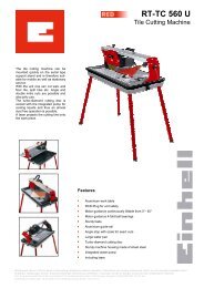
Check and adjust the position of the ignition<br />
electrode as shown in Fig. 6.<br />
After completing any maintenance and repair work<br />
you must carry out a function check of the<br />
complete equipment, checking all gas supply<br />
connections for leaks (e.g. with a leakage<br />
detection spray or soap suds) and performing an<br />
electrical safety test in accordance with VDE<br />
0701.<br />
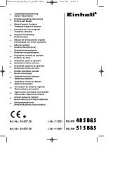
7. Terminal diagram (Pic 7)<br />
Q1 On/Off switch<br />
F1 Safety thermostat<br />
M1 Fan motor<br />
Y1 Thermoelectric ignition fuse<br />
Y2 Safety solenoid valve<br />
B1 Thermoelement<br />
B2 Piezo ignition<br />
B3 Ignition electrode<br />
B4 Burner