
Create successful ePaper yourself
Turn your PDF publications into a flip-book with our unique Google optimized e-Paper software.
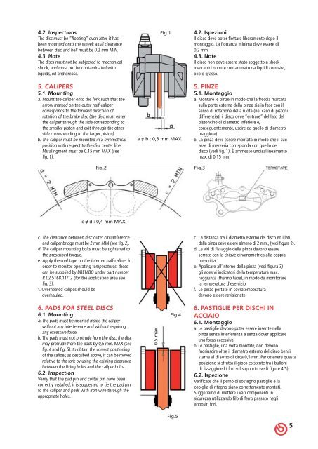
4.2. Inspections<br />
The disc must be “floating” even after it has<br />
been mounted onto the wheel: axial clearance<br />
between disc and bell must be 0.2 mm MIN.<br />
4.3. Note<br />
The discs must not be subjected to mechanical<br />
shock, and must not be contaminated with<br />
liquids, oil and grease.<br />
5. CALIPERS<br />
5.1. Mounting<br />
a. Mount the caliper onto the fork such that the<br />
arrow marked on the outer half-caliper<br />
corresponds to the forward direction of<br />
rotation of the brake disc (the disc must enter<br />
the caliper through the side corresponding to<br />
the smaller piston and exit through the other<br />
side corresponding to the larger piston).<br />
b. The caliper must be mounted in a symmetrical<br />
position with respect to the disc center line:<br />
Misalingment must be 0.15 mm MAX (see<br />
fig. 1).<br />
Fig.2<br />
c = d : 0,4 mm MAX<br />
/<br />
c. The clearance between disc outer circumference<br />
and caliper bridge must be 2 mm MIN (see fig. 2).<br />
d. The caliper mounting bolts must be tightened to<br />
the prescribed torque.<br />
e. Apply thermal tape on the internal half-caliper in<br />
order to monitor operating temperatures: these<br />
can be supplied by BREMBO under part number<br />
R 02.5168.11/12 (for the application area see<br />
fig. 3).<br />
f. Overheated calipes should be<br />
overhauled.<br />
6. PADS FOR STEEL DISCS<br />
6.1. Mounting<br />
a. The pads must be inserted inside the caliper<br />
without any interference and without requiring<br />
any excessive force.<br />
b. The pads must not protrude from the disc; the disc<br />
may protrude from the pads by 0,5 mm. MAX (see<br />
fig. 4 and fig. 5); to obtain the correct positioning<br />
of the caliper, as described above, it can be moved<br />
relative to the fork by using the existing clearance<br />
between the fixing holes and the caliper bolts.<br />
6.2. Inspection<br />
Verify that the pad pin and cotter pin have been<br />
correctly installed; it is suggested to tie the pad pin<br />
to the caliper and pads with iron wire through the<br />
appropriate holes.<br />
Fig.1<br />
a = b : 0,3 mm MAX<br />
/<br />
x<br />
a<br />
m<br />
5<br />
.<br />
0<br />
Fig.4<br />
Fig.5<br />
4.2. Ispezioni<br />
Il disco deve poter flottare liberamente dopo il<br />
montaggio. La flottanza minima deve essere di<br />
0,2 mm.<br />
4.3. Note<br />
Il disco non deve essere stato soggetto a shock<br />
meccanici oppure contaminato da liquidi corrosivi,<br />
olio o grasso.<br />
5. PINZE<br />
5.1. Montaggio<br />
a. Montare le pinze in modo che la freccia marcata<br />
sulla parte esterna della pinza sia in fase con il<br />
senso di rotazione della ruota (nel caso di pistoni<br />
differenziati il disco deve “entrare” del lato del<br />
pistoncino di diametro inferiore e,<br />
conseguentemente, uscire da quello di diametro<br />
maggiore).<br />
b. La pinza deve essere montata in modo che il suo<br />
asse di mezzeria corrisponda con quello del<br />
disco (vedi fig. 1). È ammesso undisallineamento<br />
max. di 0,15 mm.<br />
Fig.3<br />
c. La distanza tra il diametro esterno del disco ed i lati<br />
della pinza deve essere almeno di 2 mm., (vedi figura 2).<br />
d. Le viti di fissaggio della pinza devono essere<br />
serrate con la chiave dinamometrica alla coppia<br />
prescritta.<br />
e. Applicare all’interno della pinza (vedi figura 3)<br />
gli adesivi indicatori della temperatura max.<br />
raggiunta (thermo tape), in modo da monitorare<br />
la temperatura d’esercizio.<br />
f. Le pinze portate in sovratemperatura<br />
devono essere revisionate.<br />
6. PASTIGLIE PER DISCHI IN<br />
ACCIAIO<br />
6.1. Montaggio<br />
a. Le pastiglie devono poter essere inserite nella<br />
pinza senza interferenza e senza dover applicare<br />
una forza eccessiva.<br />
b. Le pastiglie, una volta montate, non devono<br />
fuoriuscire oltre il diametro esterno del disco bensì<br />
starne al di sotto di circa 0,5 mm. Per ottenere questa<br />
posizione si sfrutta il gioco esistente tra i bulloni<br />
di fissaggio ed i fori sul supporto (vedi figure 4/5).<br />
6.2. Ispezione<br />
Verificate che il perno di sostegno pastiglie e la<br />
copiglia di ritegno siano correttamente montati.<br />
Suggeriamo di mettere i vari componenti in<br />
sicurezza utilizzando filo di ferro passato negli<br />
appositi fori.<br />
5