DIGI-5 has 5 FUNCTIONS: SPD, DST, ODO, CLK, SCAN
DIGI-5 has 5 FUNCTIONS: SPD, DST, ODO, CLK, SCAN
DIGI-5 has 5 FUNCTIONS: SPD, DST, ODO, CLK, SCAN
- No tags were found...

Create successful ePaper yourself
Turn your PDF publications into a flip-book with our unique Google optimized e-Paper software.
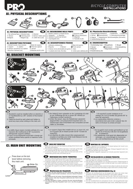
SSBICYCLE COMPUTERINSTALLATIONSA). PHYSICAL DESCRIIPTIONS1234SENSOR567 8(S)(L)SA). PHYSICAL DESCRIIPTIONS1.Twin adhesive(Tape) 2. Bracket base 3. Bracket4. Sensor S. Sensing point 5. Sensor rubber pad6.Magnet 7.Magnet cap 8. Cable ties (L)(S)EN A). DESCRIZIONE DELLE PARTIIT A). Physische Beschreibung DE1.(Nastro) adesivo a doppia faccia 2.Supporto staffa3. Supporto 4. Sensore S. Punto di rilevazione5. Spessore in gomma per sensore 6. Magnete7. Coprimagnete (vite) 8. Fascette (L)(S)1.Doppelseitiges Klebeband 2.Halterbasis 3. Halterung4. Sensor S. Sensorbereich 5. Sensorgummiunterlage6. Magnet 7. Magnetischer Verschlussstopfen (Schraube)8. Kabelbefestigung(L)(S)A). DESCRIPTION PHYSIQUEFR1.Adhésif double- face (bande) 2.Base de support3. support 4. capteur S. Point de capture5. tampon caoutchouc du capteur 6. aimant7.Bouchon d’aimant (vis)8.Attaches de fil (L)(S)B). BRACKET MOUNTINGA). DESCRIPCIONES FÍSICASES1.Adhesivo doble(cinta)2.Base del soporte3.Soporte 4.Sensor S.Punto sensor5. Sensor de la almohadilla de goma 6. Imán7. Cubierta del imán (Tornillo) 8. Unión para cables(L)(S)NLA). EIGENSCHAPPEN1.Dubbelzijdige tape 2.Beugelbasis 3. Beugel4. Sensor S.Sensorpunt 5.Sensorpakking6.Magneet7.Magneetkap (schroef)8.Kabelbinders(L)(S)B-a.321128(L)B-b.328 (L)112EN1. Bracket(3) could be installed either on stem(A) oron handlebar(B) by a 90° variation of the bracketbase(2).2. Cable tie should be well cutted and hidden toavoid any injury when sliding on the main unit.IT1.La staffa (3)può essere montata sull'asta (A) o sulmanubrio (B) modificando di 90° la posizionedell'apposito supporto staffa(2).2.Il cavo va accuratamente accorciato e riposto perevitare qualsiasi ferita quando si inserisce l'unitàprincipale.DE1.Der Halter(3) kann entweder an der Lenkstange (A) oderan der Griffstange (B) bis zu einem 90°-Winkel zurHalterbasis montiert werden(2).2.Achten Sie darauf, dass die Kabelbinden säuberlichabgeschnitten und entsprechend kaschiert sind, umVerletzungen beim Einschieben des Computers auf denHalter zu vermeiden.FR1.Le support (3)peut être installé soit sur un rayon (A), soitsur le guidon (B) en faisant pivoter de 90 º la base desupport(2).2.Les attaches de câble doivent être soigneusementcoupées et cachées pour éviter toute blessure lors del’insertion de l’unité principale.ES1.El soporte(3) puede instalarse en elvástago (A) o en el manillar (B) girando 90° labase del soporte(2).2.Los sujetacables deberían cortarse yesconderse bien para evitar cualquier tipo dedaño al introducir la unidad principal.NL1.De beugel(3) moet worden geïnstalleerd op hetventiel (A) of het stuur (B) door de beugelbasis90 te draaien(2) .2.De kabelbinder moet goed zijn afgesneden enverborgen, om verwondingen te voorkomenals u de hoofdeenheid op de fiets schuift.C). MAIN UNIT MOUNTINGLeverPress down on this locklever before removingthe main unit.Slide OnPRESSBRACKETEN MAIN UNIT MOUNTING1. Mount the main unit onto the bracket by sliding it from front to reartill it clicks into position.2. This bracket is designed with a lock lever. It can lock up the mainunit, ensuring that the main unit will not drop out while riding.3. To remove the main unit, press down on the lock lever of thebracket then pull the main unit forward and off.IT MONTAGGIO DELL’UNITA’ PRINCIPALE1. Montare l’unità principale sul supporto a slitta facendola scorreredal davanti verso dietro finché non scatta nella sua posizione.2. Il supporto è dotato di una leva a scatto che permette di fissare l’unitàprincipale impedendo che questa scivoli fuori durante la corsa.3. Per rimuovere l’unità principale, premere verso il basso leva dibloccaggio del supporto e poi sfilare l’unità principale tirandola inavanti.DE Montierung der Hauptteils1. Schieben Sie das Hauptteil auf die Halterung, indem Sie esvon vorne nach hinten schieben, bis es in seine Positioneinrastet.2. Die Halterung ist mit einem Verschlußhebel entwickelt. Dieserstellt sicher, daß das Hauptteil während der Fahrt nichtabfallen kann.3. Um das Hauptteil zu lösen, drücken Sie den Verschlußhebelund ziehen Sie das Hauptteil nach vorn, bis Sie es gelösthaben.FR MONTAGE DE L’APPAREIL1. Montez l’appareil sur le support en le faisant glisser de l’avant versl’arrière jusqu’à ce qu’il s’enclenche.2. Ce support comporte un levier de blocage. Il bloque l’appareil: ainsi il netombera pas pendant que vous roulez.3. Pour démonter l’appareil, appuyez sur le levier puis tirez l’appareil versl’avant.ES INSTALACIÓN DE LA UNIDAD PRINCIPAL1. Instale la unidad principal en el bandaje deslizándola de delante hacia atrás<strong>has</strong>ta que haga clic y encaje en su posición.2. Este bandaje ha sido diseñado con una palanca de cierre. Puede bloquear launidad principal, asegurando que la unidad principal no se caerá mientras seesté montando en bicicleta.3. Para retirar la unidad principal, presione hacia abajo la palanca de cierre delbandaje y después empuje hacia abajo y luego hacia fuera la unidad principal.NL MONTAGE HOOFDEENHEID (Fig. G)1. Monteer de hoofdeenheid op de beugel door deze van voren naarachteren te schuiven totdat de eenheid in zijn positie vastklikt.2. Deze beugel is uitgerust met een hendel. Met de hendel kan dehoofdeenheid worden vastgezet, zodat deze niet kan losraken tijdenshet rijden.3. Om de hoofdeenheid te verwijderen drukt u de beugelhendel naarbeneden en trekt u de hoofdeenheid naar voren, totdat deze los komt.